CN107766978B - Intelligent optimization method for irregular well pattern - Google Patents
Intelligent optimization method for irregular well patternDownload PDFInfo
- Publication number
- CN107766978B CN107766978BCN201710990708.XACN201710990708ACN107766978BCN 107766978 BCN107766978 BCN 107766978BCN 201710990708 ACN201710990708 ACN 201710990708ACN 107766978 BCN107766978 BCN 107766978B
- Authority
- CN
- China
- Prior art keywords
- well
- well pattern
- row
- pattern
- wells
- Prior art date
- Legal status (The legal status is an assumption and is not a legal conclusion. Google has not performed a legal analysis and makes no representation as to the accuracy of the status listed.)
- Active
Links
Images


Classifications
- G—PHYSICS
- G06—COMPUTING OR CALCULATING; COUNTING
- G06Q—INFORMATION AND COMMUNICATION TECHNOLOGY [ICT] SPECIALLY ADAPTED FOR ADMINISTRATIVE, COMMERCIAL, FINANCIAL, MANAGERIAL OR SUPERVISORY PURPOSES; SYSTEMS OR METHODS SPECIALLY ADAPTED FOR ADMINISTRATIVE, COMMERCIAL, FINANCIAL, MANAGERIAL OR SUPERVISORY PURPOSES, NOT OTHERWISE PROVIDED FOR
- G06Q10/00—Administration; Management
- G06Q10/04—Forecasting or optimisation specially adapted for administrative or management purposes, e.g. linear programming or "cutting stock problem"
- G—PHYSICS
- G06—COMPUTING OR CALCULATING; COUNTING
- G06Q—INFORMATION AND COMMUNICATION TECHNOLOGY [ICT] SPECIALLY ADAPTED FOR ADMINISTRATIVE, COMMERCIAL, FINANCIAL, MANAGERIAL OR SUPERVISORY PURPOSES; SYSTEMS OR METHODS SPECIALLY ADAPTED FOR ADMINISTRATIVE, COMMERCIAL, FINANCIAL, MANAGERIAL OR SUPERVISORY PURPOSES, NOT OTHERWISE PROVIDED FOR
- G06Q50/00—Information and communication technology [ICT] specially adapted for implementation of business processes of specific business sectors, e.g. utilities or tourism
- G06Q50/02—Agriculture; Fishing; Forestry; Mining
Landscapes
- Engineering & Computer Science (AREA)
- Business, Economics & Management (AREA)
- Human Resources & Organizations (AREA)
- Economics (AREA)
- Strategic Management (AREA)
- Physics & Mathematics (AREA)
- Tourism & Hospitality (AREA)
- Theoretical Computer Science (AREA)
- Marketing (AREA)
- General Physics & Mathematics (AREA)
- General Business, Economics & Management (AREA)
- Quality & Reliability (AREA)
- Animal Husbandry (AREA)
- Game Theory and Decision Science (AREA)
- Operations Research (AREA)
- Entrepreneurship & Innovation (AREA)
- Life Sciences & Earth Sciences (AREA)
- Agronomy & Crop Science (AREA)
- Development Economics (AREA)
- Marine Sciences & Fisheries (AREA)
- Mining & Mineral Resources (AREA)
- Health & Medical Sciences (AREA)
- General Health & Medical Sciences (AREA)
- Primary Health Care (AREA)
- Management, Administration, Business Operations System, And Electronic Commerce (AREA)
Abstract
Translated fromChinese
Description
Translated fromChinese技术领域technical field
本发明涉及石油开采技术领域,特别是指一种不规则井网的智能优化方法。The invention relates to the technical field of petroleum exploitation, in particular to an intelligent optimization method of irregular well pattern.
背景技术Background technique
复杂断块油藏由于断块分割作用,断块碎小、形态各异,每个断块就是一个独立的开发单元。在开发时由于断块面积小,很难用完善的常规面积井网进行布井、生产,因此小断块油藏一般只能采用不完善的井网进行开发。In complex fault-block reservoirs, due to the division of fault blocks, the fault blocks are small and have different shapes, and each fault block is an independent development unit. During development, due to the small fault block area, it is difficult to use a perfect conventional area well pattern for well layout and production. Therefore, small fault block oil reservoirs can generally only be developed with an imperfect well pattern.
在井位部署过程中,需要通过设计、调节井网结构,达到提高采收率(或最大化净现值)的目的。针对小断块油藏,目前国内主要是人为制定和基于优化理论的自动化井位优化方法,并在此基础上进行优化,目前,针对小断块的井网优化主要有两种方法:In the process of well location deployment, it is necessary to design and adjust the well pattern structure to achieve the purpose of enhancing oil recovery (or maximizing net present value). For small fault block oil reservoirs, at present, the automatic well location optimization method is mainly artificially formulated and based on optimization theory, and optimization is carried out on this basis. At present, there are two main methods for well pattern optimization for small fault blocks:
1)根据油藏地质情况,人为制定若干井网方案,采用油藏数值模拟方法进行模拟计算,并对各方案计算结果进行对比,从而确定最佳方案。该方法简便易行,但过分依赖人的经验,而且由于油藏地质不确定性因素多,人为制定方案数量有限,不易得到最优解。1) According to the reservoir geological conditions, artificially formulate several well pattern schemes, use the reservoir numerical simulation method for simulation calculation, and compare the calculation results of each scheme to determine the best scheme. This method is simple and easy to implement, but relies too much on human experience, and because of the many uncertainties in reservoir geology, the number of artificially formulated schemes is limited, and it is difficult to obtain the optimal solution.
2)采用基于优化理论的自动化井位优化方法。主要思路是首先根据需要设定一个目标函数(净现值或采收率等),然后借助于某种智能优化算法(粒子群、遗传算法、模拟退火等),调用数值模拟软件得出使目标函数最优的解。该方法可以极大的减少人工工作量。2) Adopt the automatic well location optimization method based on optimization theory. The main idea is to first set an objective function (net present value or recovery factor, etc.) as needed, and then use some intelligent optimization algorithm (particle swarm, genetic algorithm, simulated annealing, etc.) to call numerical simulation software to obtain the objective. the optimal solution of the function. This method can greatly reduce the manual workload.
相比于第一种方法,第二种以智能优化算法为基础的井网优化方法更具一般性,因此未来的应用前景更加广阔。Compared with the first method, the second well pattern optimization method based on the intelligent optimization algorithm is more general, so the future application prospect is broader.
目前众多智能井网优化方法的主要差异集中在程序内部采用的优化算法各不相同,包括遗传算法、粒子群算法、蚁群算法、模拟退火算法、捕食搜索算法等。不同算法的主要差别是收敛速度和计算量。只要计算资源、计算时间充足,不同优化算法的结果不会有明显差异。因此,井网优化问题的本质和关键点并不是其内部的智能优化算法,而是待优化的目标本身。目前井网优化研究的目标可以分为以下两类:At present, the main difference of many intelligent well pattern optimization methods is that the optimization algorithms used in the program are different, including genetic algorithm, particle swarm algorithm, ant colony algorithm, simulated annealing algorithm, prey search algorithm, etc. The main difference between the different algorithms is the convergence speed and the amount of computation. As long as the computing resources and computing time are sufficient, the results of different optimization algorithms will not be significantly different. Therefore, the essence and key point of the well pattern optimization problem is not its internal intelligent optimization algorithm, but the target itself to be optimized. The objectives of the current well pattern optimization research can be divided into the following two categories:
a)直接以单井井位作为优化目标。这种方法对每口井的井位都进行独立优化,最终的井位是散乱的,不能形成井网结构,因此不能用来优化面积注水、注气是井网,同时由于不同井之间的干扰问题,优化结果一般不是最优的布井方案。a) Directly take the well position of a single well as the optimization target. This method independently optimizes the well position of each well. The final well position is scattered and cannot form a well pattern structure. Therefore, it cannot be used to optimize the area of water injection and gas injection. Interference problem, the optimization result is generally not the optimal well layout plan.
b)确定井网类型(五点、七点、九点等)后,对井网的井距、排距和并排角度进行优化,通过反复的数值模拟和迭代进化,获得最佳的井距、排距、并排角度参数。这种方法的缺点是所优化的井网只能是严格的规则井网,但在实际油气藏的圈闭范围是不规则的,且大部分油藏地质结构复杂,油层分布多样,导致采用严格的规则井网(即井距、排距始终保持一致)不能获得最大的生产效益。b) After determining the well pattern type (five points, seven points, nine points, etc.), optimize the well spacing, row spacing and side-by-side angle of the well pattern, and obtain the best well spacing, Row spacing, side-by-side angle parameters. The disadvantage of this method is that the optimized well pattern can only be a strict regular well pattern, but in actual oil and gas reservoirs, the trap range is irregular, and most of the reservoirs have complex geological structures and diverse oil layer distributions, which lead to strict The regular well pattern (that is, the well spacing and row spacing are always consistent) cannot obtain the maximum production benefit.
另外,在实际生产过程中,规则井网的部署完成后,还需要根据油藏边界和断层位置、储层各向异性、非均质性、裂缝发育区域等因素进行微调,从而尽可能提高油气采收率或最大净现值。In addition, in the actual production process, after the deployment of the regular well pattern is completed, it is necessary to fine-tune according to the reservoir boundary and fault location, reservoir anisotropy, heterogeneity, fracture development area and other factors, so as to improve the oil and gas as much as possible. Recovery factor or maximum net present value.
发明内容SUMMARY OF THE INVENTION
本发明提供一种充分考虑到油藏边界和断层位置、储层各向异性、非均质性、裂缝发育区域等因素,且能提高油藏采收率或净现值,能直接用于油气藏开发方案的设计和钻井施工的不规则井网的智能优化方法。The invention provides a method that fully considers factors such as reservoir boundary and fault location, reservoir anisotropy, heterogeneity, fracture development area, etc., and can improve oil recovery or net present value, and can be directly used for oil and gas. Intelligent optimization method of irregular well pattern in the design of reservoir development plan and drilling construction.
为解决上述技术问题,本发明提供技术方案如下:In order to solve the above-mentioned technical problems, the present invention provides the following technical solutions:
一种不规则井网的智能优化方法,包括:An intelligent optimization method for irregular well pattern, including:
步骤1:提取区块的几何边界;Step 1: Extract the geometric boundary of the block;
步骤2:生成待优化的初始井网参数:排距、井距和井排方向;Step 2: Generate the initial well pattern parameters to be optimized: row spacing, well spacing and well row direction;
步骤3:任意选择一点作为生成初始井网的原点,生成基本井排,移动所述基本井排,生成初始井网;Step 3: arbitrarily select a point as the origin for generating the initial well pattern, generate a basic well row, move the basic well row, and generate an initial well pattern;
步骤4:在所述初始井网下进行油藏数值模拟,获得全油藏日产油、日产水、和日产气曲线;Step 4: carry out numerical simulation of the oil reservoir under the initial well pattern to obtain the daily oil production, daily water production, and daily gas production curves of the entire reservoir;
步骤5:以采收率或净现值为目标函数,采用智能优化方法对所述初始井网参数进行优化,得到最优参数组合;Step 5: taking the recovery factor or the net present value as the objective function, using the intelligent optimization method to optimize the parameters of the initial well pattern to obtain the optimal parameter combination;
步骤6:根据得到的最优参数组合,生成最优井网。Step 6: According to the obtained optimal parameter combination, the optimal well pattern is generated.
进一步的,提取几何边界时去除死网格。Further, dead meshes are removed when extracting geometric boundaries.
进一步的,所述步骤2包括:Further, the step 2 includes:
步骤21:在油藏所在空间的平面内设置代表点集合P,代表点在油藏平面内均匀分布,记代表点pi的坐标为(alp,blp),lp是相邻代表点之间的距离,a、b为任意自然数,确定区块内代表点的lp的初始值;Step 21: Set the representative point set P in the plane of the space where the reservoir is located, and the representative points are evenly distributed in the reservoir plane. The coordinates of the representative point pi are recorded as (alp , blp ), and lp is the difference between the adjacent representative points. The distance between , a and b are any natural numbers, determine the initial value of lp of the representative point in the block;
步骤22:确定任一代表点pi的三个待优化参数排距ci、井距di和井排方向θi的合理分布范围;Step 22: Determine the reasonable distribution range of the row spacing ci , the well spacing di and the well row direction θi of the three parameters to be optimized at any representative point pi;
步骤23:对代表点pi的三个参数排距ci、井距di和井排方向θi赋值,得到初始井网参数。Step 23: Assign values to the three parameters row spacing ci , well spacing di and well row direction θi of the representative point pi to obtain initial well pattern parameters.
进一步的,所述步骤21中,两个代表点之间的距离为lp为200~400m。Further, in the step 21, the distance between the two representative points is lp of200-400m .
进一步的,步骤22中,排距ci、井距di和井排方向θi的合理分布范围为:100m≤ci≤400m,100m≤di≤400m,0°≤θi≤90°。Further, in step 22, the reasonable distribution ranges of the row spacing ci , the well spacing di and the well row direction θi are: 100m≤ci ≤400m, 100m≤di ≤400m, 0°≤θ i≤90 ° .
进一步的,步骤3包括:Further, step 3 includes:
步骤31:以原点W11为起点利用二维平面差值的方法生成基本井排;Step 31: Using the originW11 as the starting point to generate the basic well row by using the method of two-dimensional plane difference;
步骤32:移动基本井排,生成基本井网;Step 32: Move the basic well row to generate the basic well pattern;
步骤33:剔除区块外的井;Step 33: Eliminate the wells outside the block;
步骤34:对区块内基本井网的每口井指定其为注入井或采出井;Step 34: Designate each well of the basic well pattern in the block as an injection well or a production well;
步骤35:根据基本井网映射生成初始井网。Step 35: Generate an initial well pattern according to the basic well pattern mapping.
进一步的,所述步骤34中根据井网类型指定注入井或采出井,所述井网类型为衰竭开采井网、五点井网、九点井网、反九点井网、七点井网和反七点井网。Further, in the step 34, the injection well or the production well is designated according to the well pattern type, and the well pattern type is a depleted production well pattern, a five-spot well pattern, a nine-spot well pattern, an anti-nine-spot well pattern, and a seven-spot well pattern. And the anti-seven-point well network.
进一步的,所述衰竭开采井网中的全部井均为采出井;Further, all wells in the depleted production well pattern are production wells;
所述五点井网为一排间隔采出井、注入井,相邻的一排间隔注入井、采出井;The five-spot well pattern is a row of spaced production wells and injection wells, and an adjacent row of spaced injection wells and production wells;
所述九点井网为一排采出井,相邻的一排间隔采出井、注入井;The nine-spot well pattern is a row of production wells, and an adjacent row of production wells and injection wells are spaced;
所述反九点井网为一排注入井,相邻的一排间隔注入井、采出井;The reverse nine-spot well pattern is a row of injection wells, and an adjacent row of injection wells and production wells are spaced;
所述七点井网为一排间隔两口采出井、一口注入井,相邻的一排间隔一口注入井、两口采出井;The seven-spot well pattern consists of two production wells and one injection well in a row, and one injection well and two production wells in an adjacent row;
所述反七点井网为一排间隔一口采出井、两口注入井,相邻的一排间隔两口注入井、一口采出井。The reverse seven-spot well pattern consists of one production well and two injection wells in a row, and two injection wells and one production well in an adjacent row.
进一步的,所述步骤5中,所述智能优化方法包括遗传算法、粒子群算法、蚁群算法、模拟退火算法、捕食搜索算法。Further, in the step 5, the intelligent optimization method includes genetic algorithm, particle swarm algorithm, ant colony algorithm, simulated annealing algorithm, and predation search algorithm.
进一步的,所述步骤5中,所述目标函数为采收率,优化后的井网的井数需要设定布井上限。Further, in the step 5, the objective function is the recovery factor, and the number of wells in the optimized well pattern needs to set an upper limit for well layout.
本发明具有以下有益效果:The present invention has the following beneficial effects:
1)本发明是一种油气藏开发井网的智能化、自动化优化方法,本发明的优化方法是以地质模型的数值模拟结果为基础进行的智能优化,该区块的储层各向异性、非均质性、裂缝发育区域等因素都会反映在地质模型中,所以本发明的不规则井网的智能优化方法也是充分考虑了储层各向异性、非均质性、裂缝发育区域等因素;1) The present invention is an intelligent and automatic optimization method for oil and gas reservoir development well patterns. The optimization method of the present invention is an intelligent optimization based on the numerical simulation results of a geological model. The reservoir anisotropy, Factors such as heterogeneity and fracture development area will be reflected in the geological model, so the intelligent optimization method of the irregular well pattern of the present invention also fully considers the reservoir anisotropy, heterogeneity, fracture development area and other factors;
2)本发明通过初始井网参数生成初始井网,然后再进行数值模拟,采用智能优化方法对初始井网参数进行优化,得到最优的参数组合,进而生成最合适该区块的井网结构,本发明生成的井网是完全针对区块地质特征和精细构造的最优井网,因此,可以获得最高的采收率或净现值(取决于优化的目标函数);2) The present invention generates the initial well pattern through the initial well pattern parameters, and then carries out numerical simulation, adopts the intelligent optimization method to optimize the initial well pattern parameters, obtains the optimal parameter combination, and then generates the most suitable well pattern structure for the block. , the well pattern generated by the present invention is the optimal well pattern completely aiming at the geological characteristics and fine structure of the block, therefore, the highest recovery factor or net present value (depending on the optimized objective function) can be obtained;
3)本发明克服了传统的人工对比的井网优化方法过分依赖人的经验、人工工作量大的缺点;同时,克服了传统的规则型井网优化方法获得的井网不能很好适应具体油藏的缺点,利用本发明获得的井网可以直接应用于油气藏开发方案的设计和钻井施工。3) The present invention overcomes the shortcomings of the traditional manual comparison well pattern optimization method that relies too much on human experience and the manual workload is large; at the same time, it overcomes that the well pattern obtained by the traditional regular well pattern optimization method cannot be well adapted to specific oil. In view of the shortcomings of the reservoir, the well pattern obtained by the invention can be directly applied to the design of the oil and gas reservoir development scheme and the drilling construction.
附图说明Description of drawings
图1为本发明的不规则井网的智能优化方法的流程图;Fig. 1 is the flow chart of the intelligent optimization method of irregular well pattern of the present invention;
图2为本发明的实施例1中区块的地质模型及渗透率分布;Fig. 2 is the geological model and permeability distribution of block in the
图3为本发明的实施例1中根据地质模型提取出的几何边界;3 is a geometrical boundary extracted according to a geological model in
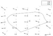
图4为本发明的实施例1中待优化的初始井网参数;Fig. 4 is the initial well pattern parameter to be optimized in
图5为本发明的实施例1中基本井排;Fig. 5 is the basic well row in the
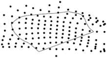
图6为本发明的实施例1中通过移动基本井排生成的初始井网;6 is an initial well pattern generated by moving a basic well row in Example 1 of the present invention;
图7为本发明的实施例1中剔除区块以外的井后剩余的井网;Fig. 7 is the remaining well pattern after removing the wells other than the block in Example 1 of the present invention;
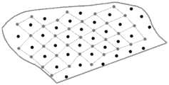
图8为本发明的实施例1中对区块内基本井网的每口井指定为注入井或采出井后的井网;8 is the well pattern after each well of the basic well pattern in the block is designated as an injection well or a production well in Example 1 of the present invention;
图9(a)为本发明实施例1中使用粒子群算法进行优化的第1代;Figure 9(a) is the first generation optimized by particle swarm optimization in
图9(b)为本发明实施例1中使用粒子群算法进行优化的第5代;Figure 9(b) is the fifth generation optimized by particle swarm optimization in
图9(c)为本发明实施例1中使用粒子群算法进行优化的第9代;Figure 9(c) is the ninth generation optimized by particle swarm optimization in
图9(d)为本发明实施例1中使用粒子群算法进行优化的第17代。FIG. 9(d) is the 17th generation optimized by using the particle swarm algorithm in
具体实施方式Detailed ways
为使本发明要解决的技术问题、技术方案和优点更加清楚,下面将结合附图及具体实施例进行详细描述。In order to make the technical problems, technical solutions and advantages to be solved by the present invention more clear, the following will be described in detail with reference to the accompanying drawings and specific embodiments.
本发明需要建立一套完整的参数系统以及对应的构造井网的办法,且要求:The present invention needs to establish a complete parameter system and a corresponding method for constructing well pattern, and requires:
1)各参数物理意义明确、相互独立;1) The physical meaning of each parameter is clear and independent of each other;
2)使用这组参数能够构造出一个唯一的注采井网。2) Using this set of parameters, a unique injection-production well pattern can be constructed.
满足这两个需求,即可通过任意一种智能优化方法对这组参数进行最优化,由于参数和井网一一对应,因此也就实现了对井网的最优化。If these two requirements are met, this set of parameters can be optimized by any intelligent optimization method. Since the parameters correspond to the well pattern one by one, the optimization of the well pattern is also realized.
本发明提供一种不规则井网的智能优化方法,如图1~9(d)所示,包括:The present invention provides an intelligent optimization method for irregular well pattern, as shown in Figures 1 to 9(d), including:
步骤1:提取区块的几何边界,具体的,对地质建模获得的油藏地质模型提取油藏外的几何边界,地质建模时需考虑该区块的该区块的储层各向异性、非均质性、裂缝发育区域等因素,地质模型的建立是根据常规的地质建模过程建立的,此处不再赘述;几何边界记为L,该几何边界L可以是由断层构成的封闭边界,也可以是人为画出的几何边界,几何边界L确定后,未来的布井工作只在L内进行;需要指出的是,提取几何边界时,需要将死网格(ACTNUN=0的网格)刨除在外,因为在死网格中布井也是无效的;Step 1: Extract the geometric boundary of the block. Specifically, extract the geometric boundary outside the oil reservoir from the reservoir geological model obtained by geological modeling. The reservoir anisotropy of the block in the block needs to be considered in the geological modeling. , heterogeneity, fracture development area and other factors, the establishment of the geological model is established according to the conventional geological modeling process, which will not be repeated here; The boundary can also be an artificially drawn geometric boundary. After the geometric boundary L is determined, the future well layout work will only be carried out within L; grid) is excluded, because it is also invalid to arrange wells in a dead grid;
步骤2:生成待优化的初始井网参数:排距ci、井距di和井排方向θi,具体的,包括:Step 2: Generate initial well pattern parameters to be optimized: row spacing ci , well spacing di and well row direction θi , specifically, including:
步骤21:在油藏所在空间的平面内设置代表点集合P,代表点在油藏平面内均匀分布,记代表点pi的坐标为(alp,blp),lp是相邻代表点之间的距离(固定值),a、b为任意自然数,这样的pi有无穷多个,只保留处于区块范围内的即可,记最终保留的代表点的个数为np,代表点之间的距离lp越小,代表点越多,优化结果越细致,但优化的计算量越大,因此,lp的值需要根据油藏的实际地质情况(如储层各向异性、非均质性等)确定,储层的非均质性越强,lp应该越小,反之则可以较大;一般的,lp在200m-400m之间;Step 21: Set the representative point set P in the plane of the space where the reservoir is located, and the representative points are evenly distributed in the reservoir plane. The coordinates of the representative point pi are recorded as (alp , blp ), and lp is the adjacent representative point The distance between (a fixed value), a and b are any natural numbers, there are infinitely many such pi , only those within the range of the block can be reserved, and the number of representative points that are finally reserved is np , representing The smaller the distance lp between the points, the more representative points, and the more detailed the optimization results, but the greater the amount of optimization calculation, therefore, the value of lp needs to be based on the actual geological conditions of the reservoir (such as reservoir anisotropy, Heterogeneity, etc.) to determine, the stronger the heterogeneity of the reservoir, the smaller thelp should be, otherwise it can be larger; generally, thelp is between 200m-400m;
步骤22:确定任一代表点pi的三个待优化参数排距ci、井距di和井排方向θi的合理分布范围;该步骤需要结合具体的油藏特征进行分析、确定,一般来说,三个待优化参数可以设为:100m≤ci≤400m,100m≤di≤400m,0°≤θi≤90°;其中,三个待优化参数的范围涵盖了大部分油藏排距、井距、井排方向的取值可能,但如果油藏渗透率较低(例如<1mD),可以将ci、di的取值上限放大到600m;Step 22: Determine the reasonable distribution range of the row spacingci, well spacing d i and well row direction θ iofthe three parameters to be optimized at any representative point pi ; Generally speaking, the three parameters to be optimized can be set as: 100m≤ci ≤400m, 100m≤di ≤400m, 0°≤θ i≤90 °; the range of the three parameters to be optimized covers most of the oil The values of reservoir row spacing, well spacing, and well row direction are possible, but if the reservoir permeability is low (for example, <1mD), the upper limit of the values of ci and d ican be enlarged to 600m;
步骤23:对代表点pi的三个参数排距ci、井距di和井排方向θi赋值,得到初始井网参数;赋值时随机赋值即可,但需要保证随机值在步骤22中的合理范围内;Step 23: Assign values to the three parameters row spacing ci , well spacing di and well row direction θi of the representative point pi to obtain the initial well pattern parameters; the assignment can be randomly assigned, but it is necessary to ensure that the random value is in step 22 within a reasonable range;
步骤3:任意选择一点作为生成初始井网的原点,生成基本井排,移动所述基本井排,生成初始井网;具体的,该步骤包括:Step 3: arbitrarily select a point as the origin for generating the initial well pattern, generate a basic well row, move the basic well row, and generate an initial well pattern; specifically, this step includes:
步骤31:在油藏中任意选择一点作为生成基本井网的原点W11,即第一个井排的第一口井,以原点W11为起点利用二维平面差值的方法生成基本井排,具体的,首先利用二维平面差值的方法,根据代表点集合P上井距di构成的数据场,计算出W11点上的井距d11,根据代表点集合P上井排方向θi构成的数据场,计算出W11点上的井排方向θ11,根据d11、θ11即可计算出同一个井排上的第二口井W12(x12,y12)的位置,计算公式为x12=x11+d11cosθ11,y12=y11+d11sinθ11,循环重复该操作,即可生成该井排上所有的井;Step 31: Select any point in the reservoir as the origin W11 for generating the basic well pattern, that is, the first well in the first well row, and use the two-dimensional plane difference method to generate the basic well row with the origin W11 as the starting point Specifically, first, using the method of two-dimensional plane difference, according to the data field formed by the well spacing di on the representative point set P, the well spacing d11 on the W11 point is calculated, and according to the well row direction θi on the representative point set P The formed data field can calculate the well row direction θ11 on the W11 point, and the position of the second well W12 (x12 , y12 ) on the same well row can be calculated according to d11 , θ11 , The calculation formula is x12 =x11 +d11 cosθ11 , y12 =y11 +d11 sinθ11 , repeat this operation cyclically to generate all the wells in the well row;
步骤32:移动基本井排,生成基本井网,具体的,将基本井排上的井W1i沿井排方向θ1i移动c1i的距离,即可形成第二个井排上的井W2i,其中,c1i是W1i点对应的排距,它是根据W1i的位置,在代表点集合P上排距ci构成的数据场中差值获得的,循环重复该操作,最终可生成一个覆盖全部区块方基本井网W;Step 32: Move the basic well row to generate a basic well pattern. Specifically, move the well W1i on the basic well row by a distance c1i along the well row direction θ1i to form the well W2i on the second well row , where c1i is the row distance corresponding to the point W1i , which is obtained from the difference in the data field formed by the row distance ci on the representative point set P according to the position of W1i . Repeat this operation cyclically, and finally generate A basic well pattern W covering all blocks;
步骤33:剔除区块外的井:针对W中的每口井Wij,判断其是否在区块范围L内,如果Wij在L内部则保留,反之,从集合W中删除该井;Step 33: Eliminate the wells outside the block: for each well Wij in W, determine whether it is within the block range L, and if Wij is within L, keep it, otherwise, delete the well from the set W;
步骤34:对区块内基本井网的每口井指定其为注入井或采出井;本步骤需要根据所选的井网类型进行执行,可选的井网类型有:衰竭开采井网、五点井网、九点井网、反九点井网、七点井网和反七点井网,针对每种井网,具体操作如下:Step 34: Designate each well of the basic well pattern in the block as an injection well or a production well; this step needs to be performed according to the selected well pattern type. The optional well pattern types are: depleted production well pattern, five Spot well pattern, nine-spot well pattern, reverse nine-spot well pattern, seven-spot well pattern and reverse seven-spot well pattern, for each well pattern, the specific operations are as follows:
a、衰竭开采井网:全部井均为采出井;a. Depleted production well pattern: all wells are production wells;
b、五点井网:一排间隔采出井、注入井,相邻的一排间隔注入井、采出井;b. Five-spot well pattern: a row of interval production wells and injection wells, and an adjacent row of interval injection wells and production wells;
c、九点井网:一排采出井,相邻的一排间隔采出井、注入井;c. Nine-spot well pattern: a row of production wells, and an adjacent row of production wells and injection wells at intervals;
d、反九点井网:一排注入井,相邻的一排间隔注入井、采出井;d. Reverse nine-spot well pattern: one row of injection wells, and one row of adjacent injection wells and production wells;
e、七点井网:一排间隔采出井(2口)、注入井(1口),相邻的一排间隔注入井(1口)、采出井(2口);e. Seven-spot well pattern: a row of spaced production wells (2) and injection wells (1), and an adjacent row of spaced injection wells (1) and production wells (2);
f、反七点井网:一排间隔采出井(一口)、注入井(2口),相邻的一排间隔注入井(2口)、采出井(1口);f. Reverse seven-spot well pattern: a row of spaced production wells (one) and injection wells (2), and an adjacent row of spaced injection wells (2) and production wells (1);
步骤35:根据基本井网映射生成初始井网;Step 35: Generate an initial well pattern according to the basic well pattern mapping;
步骤4:在得到的初始井网下进行油藏数值模拟,获得全油藏日产油、日产水和日产气曲线,并以此为基础计算采收率或净现值;油藏数值模拟是一种常规的利用计算机计算地层中油、气、水流动过程的技术手段,能够给出任意时刻的油气水分布,并预测油藏动态,油藏数值模拟首先需要建立准确的地质模型(网格模型和属性模型),在此基础上,需要准备流体高压物性数据和相渗曲线数据,再根据质量守恒方程计算所有网格中的流体流动;Step 4: Carry out numerical simulation of the reservoir under the obtained initial well pattern, obtain the daily oil production, daily water production and daily gas production curves of the whole reservoir, and calculate the recovery factor or net present value based on this; It is a conventional technical means to use computer to calculate the flow process of oil, gas and water in the formation, which can give the distribution of oil, gas and water at any time, and predict the performance of the reservoir. The numerical simulation of the reservoir first requires the establishment of an accurate geological model (grid model and On this basis, it is necessary to prepare the fluid high-pressure physical property data and phase permeability curve data, and then calculate the fluid flow in all grids according to the mass conservation equation;
步骤5:以采收率或净现值为目标函数,采用智能优化方法,反复进行布井和数值模拟(即重复步骤3、步骤4),对所有代表点上的待优化参数(排距ci、井距di和井排方向θi)进行优化,需要指出的是:Step 5: Take the recovery factor or the net present value as the objective function, and use the intelligent optimization method to repeatedly perform well layout and numerical simulation (that is, repeat steps 3 and 4).i , well spacing di and well row direction θi ) are optimized. It should be pointed out that:
a、无论哪种智能优化算法(即启发式的优化算法)皆可用于此步骤的优化,包括但不限于遗传算法、粒子群算法、蚁群算法、模拟退火算法、捕食搜索算法等;以粒子群算法为例,优化的过程是:初始为一群随机粒子(参数随机组合),在每一次迭代中,通过数值模拟,计算出该粒子对应的目标函数值,粒子通过跟踪两个“极值”来更新自己的位置(参数设置),第一个就是粒子本身所找到的最大目标函数时的参数组合,这个解叫做个体极值;另一个极值是整个种群目前找到最大目标函数时的参数组合,这个极值是全局极值,通过反复重复该过程,即可找到最优解;a. No matter what kind of intelligent optimization algorithm (ie heuristic optimization algorithm) can be used for the optimization of this step, including but not limited to genetic algorithm, particle swarm algorithm, ant colony algorithm, simulated annealing algorithm, prey search algorithm, etc.; Taking the swarm algorithm as an example, the optimization process is: initially a group of random particles (random combination of parameters), in each iteration, through numerical simulation, the objective function value corresponding to the particle is calculated, and the particle tracks two "extreme values" by to update its position (parameter setting), the first is the parameter combination when the particle itself finds the maximum objective function, this solution is called the individual extreme value; the other extreme value is the parameter combination when the entire population currently finds the maximum objective function , this extremum is the global extremum, and the optimal solution can be found by repeating the process repeatedly;
b、采收率或净现值均可以作为优化的目标函数,具体使用哪个参数,需要根据油藏开发的整体规划和长远目标进行确定(当使用采收率作为优化目标时,一般需要设定布井上限Wmax,即要求优化后的井网的井数≤Wmax,此时问题转化为一个简单的约束优化问题,可以在以上智能优化算法中考虑罚函数或禁忌搜索策略进行求解);b. Either the recovery factor or the net present value can be used as the objective function for optimization. The specific parameter to be used needs to be determined according to the overall planning and long-term objective of reservoir development (when the recovery factor is used as the optimization objective, it is generally necessary to set The upper limit of well layout Wmax , that is, the number of wells in the optimized well pattern is required to be ≤ Wmax , at this time the problem is transformed into a simple constrained optimization problem, which can be solved by considering the penalty function or tabu search strategy in the above intelligent optimization algorithm);
步骤6:优化完成后,根据得到的最优参数组合(代表点集合P上的排距ci、井距di和井排方向θi)重复步骤3,即可生成最优的井网。Step 6: After the optimization is completed, step 3 is repeated according to the obtained optimal parameter combination (row spacing ci, well spacing di and well row direction θi on the representative point set P) to generate the optimal well pattern.
实施例1:Example 1:
以F油田B区块为例,智能优化方法采用粒子群算法,即PSO算法,拟合目标为最大化净现值:Taking block B of F oilfield as an example, the intelligent optimization method adopts particle swarm algorithm, namely PSO algorithm, and the fitting objective is to maximize the net present value:
1、提取区块的油藏边界(即油藏边界):1. Reservoir boundary (ie, reservoir boundary) of the extraction block:
对地质建模获得的油藏地质模型(如图2)提取油藏外边界(如图3),注意提取边界时将死网格刨除在外,其中,图2为区块的地质模型及渗透率分布;Extract the outer boundary of the reservoir (as shown in Figure 3) from the reservoir geological model obtained by geological modeling (as shown in Figure 3). Pay attention to exclude the dead grids when extracting the boundary. Among them, Figure 2 shows the geological model and permeability of the block. distributed;
2、布代表点并给每个参考点三参数(井距、排距、井排方向)赋初值:2. Arrange representative points and assign initial values to the three parameters (well spacing, row spacing, and well row direction) of each reference point:
在油藏区块所在的平面上均匀布置代表点(如图4),并给代表点的三个参数(井距、排距、井排方向)赋初值,图4中黑色实心圆点是人为布置的代表点,每个代表点上有三个参数,分别为井距(用灰色箭头的长度表示)、排距(用黑色箭头的长度表示)和井排方向(用灰色箭头的方向表示),空心圆点是井网生成原点W11井的位置(可以任意选择);The representative points are evenly arranged on the plane where the reservoir block is located (as shown in Figure 4), and initial values are assigned to the three parameters (well spacing, row spacing, and well row direction) of the representative points. The black solid circles in Figure 4 are Artificially arranged representative points, each representative point has three parameters, namely well spacing (represented by the length of the gray arrow), row spacing (represented by the length of the black arrow) and well row direction (represented by the direction of the gray arrow) , the hollow circle is the position of the well pattern generation origin W11 (can be selected arbitrarily);
3、根据代表点上的参数值生成整个初始井网:3. Generate the entire initial well pattern according to the parameter values at the representative points:
首先从井网生成原点开始,生成基本井排(如图5);再移动基本井排,生成基本井网(如图6);然后剔除工区外侧的井,只保留有效井(如图7);最后根据所选择的井网类型(以五点井网为例),将有效井分为注入井、采出井两组(如图8),至此,井网生成完成,其中,图5-图7中的黑色实心圆点代表井,图8中,黑色圆点为采出井,灰色圆点为注入井,灰色实现连出的部分即注采井组完善的井组;First, start from the origin of the well pattern generation to generate the basic well pattern (as shown in Figure 5); then move the basic well pattern to generate the basic well pattern (as shown in Figure 6); then remove the wells outside the work area, and only keep the valid wells (as shown in Figure 7) ; Finally, according to the selected well pattern type (taking the five-spot well pattern as an example), the effective wells are divided into two groups: injection wells and production wells (as shown in Figure 8). So far, the well pattern generation is completed. The black solid dots in Figure 7 represent wells. In Fig. 8, the black dots are the production wells, the gray dots are the injection wells, and the part that is connected in gray is the well group with perfect injection-production well group;
4、进行开发数值模拟,计算优化的“目标函数”:4. Carry out development numerical simulation and calculate the optimized "objective function":
在以上布井的基础上,针对该区块,进行油藏开发数值模拟,根据模拟结果计算优化的“目标函数”(采收率或净现值);On the basis of the above well placement, for this block, carry out numerical simulation of reservoir development, and calculate the optimized "objective function" (recovery factor or net present value) according to the simulation results;
5、优化代表点上的参数,使目标函数最大:5. Optimize the parameters on the representative point to maximize the objective function:
采用粒子群算法对全部参考点上的三个参数(井距、排距、井排方向)进行优化,随着优化的进行,如图9(a)为优化的第1代,图9(b)为优化的第5代,图9(c)为优化的第9代,图9(d)为优化的第17代,井网结构越来越适应本研究工区,最终获得最佳的井网。The particle swarm algorithm is used to optimize the three parameters (well spacing, row spacing, and well row direction) on all reference points. ) is the optimized fifth generation, Fig. 9(c) is the optimized ninth generation, and Fig. 9(d) is the optimized 17th generation. .
综上,本发明具有以下有益效果:To sum up, the present invention has the following beneficial effects:
1)本发明是一种油气藏开发井网的智能化、自动化优化方法,本发明的优化方法是以地质模型的数值模拟结果为基础进行的智能优化,该区块的储层各向异性、非均质性、裂缝发育区域等因素都会反映在地质模型中,所以本发明的不规则井网的智能优化方法也是充分考虑了储层各向异性、非均质性、裂缝发育区域等因素;1) The present invention is an intelligent and automatic optimization method for oil and gas reservoir development well patterns. The optimization method of the present invention is an intelligent optimization based on the numerical simulation results of a geological model. The reservoir anisotropy, Factors such as heterogeneity and fracture development area will be reflected in the geological model, so the intelligent optimization method of the irregular well pattern of the present invention also fully considers the reservoir anisotropy, heterogeneity, fracture development area and other factors;
2)本发明通过初始井网参数生成初始井网,然后再进行数值模拟,采用智能优化方法对初始井网参数进行优化,得到最优的参数组合,进而生成最合适该区块的井网结构,本发明生成的井网是完全针对区块地质特征和精细构造的最优井网,因此,可以获得最高的采收率或净现值(取决于优化的目标函数);2) The present invention generates the initial well pattern through the initial well pattern parameters, and then carries out numerical simulation, adopts the intelligent optimization method to optimize the initial well pattern parameters, obtains the optimal parameter combination, and then generates the most suitable well pattern structure for the block. , the well pattern generated by the present invention is the optimal well pattern completely aiming at the geological characteristics and fine structure of the block, therefore, the highest recovery factor or net present value (depending on the optimized objective function) can be obtained;
3)本发明克服了传统的人工对比的井网优化方法过分依赖人的经验、人工工作量大的缺点;同时,克服了传统的规则型井网优化方法获得的井网不能很好适应具体油藏的缺点,利用本发明获得的井网可以直接应用于油气藏开发方案的设计和钻井施工,具有良好的应用前景,尤其适应于致密砂岩储层、裂缝发育储层等强非均质性油藏当中。3) The present invention overcomes the shortcomings of the traditional manual comparison well pattern optimization method that relies too much on human experience and manual workload; at the same time, it overcomes that the well pattern obtained by the traditional regular well pattern optimization method cannot be well adapted to specific oil. The well pattern obtained by the invention can be directly applied to the design of oil and gas reservoir development plans and drilling construction, and has good application prospects, especially suitable for tight sandstone reservoirs, fractured reservoirs and other strong heterogeneous oil reservoirs. hide in.
以上所述是本发明的优选实施方式,应当指出,对于本技术领域的普通技术人员来说,在不脱离本发明所述原理的前提下,还可以作出若干改进和润饰,这些改进和润饰也应视为本发明的保护范围。The above are the preferred embodiments of the present invention. It should be pointed out that for those skilled in the art, without departing from the principles of the present invention, several improvements and modifications can be made. It should be regarded as the protection scope of the present invention.
Claims (8)
Priority Applications (1)
| Application Number | Priority Date | Filing Date | Title |
|---|---|---|---|
| CN201710990708.XACN107766978B (en) | 2017-10-23 | 2017-10-23 | Intelligent optimization method for irregular well pattern |
Applications Claiming Priority (1)
| Application Number | Priority Date | Filing Date | Title |
|---|---|---|---|
| CN201710990708.XACN107766978B (en) | 2017-10-23 | 2017-10-23 | Intelligent optimization method for irregular well pattern |
Publications (2)
| Publication Number | Publication Date |
|---|---|
| CN107766978A CN107766978A (en) | 2018-03-06 |
| CN107766978Btrue CN107766978B (en) | 2020-03-17 |
Family
ID=61269201
Family Applications (1)
| Application Number | Title | Priority Date | Filing Date |
|---|---|---|---|
| CN201710990708.XAActiveCN107766978B (en) | 2017-10-23 | 2017-10-23 | Intelligent optimization method for irregular well pattern |
Country Status (1)
| Country | Link |
|---|---|
| CN (1) | CN107766978B (en) |
Families Citing this family (6)
| Publication number | Priority date | Publication date | Assignee | Title |
|---|---|---|---|---|
| CN110306968A (en)* | 2018-03-27 | 2019-10-08 | 中国石油化工股份有限公司 | Irregular well pattern optimization method and its computer readable storage medium |
| CN112459763A (en)* | 2019-09-06 | 2021-03-09 | 中国石油天然气股份有限公司 | Optimal arrangement method and device for gas wells in gas field |
| CN113803044B (en)* | 2020-06-17 | 2023-08-01 | 中国石油化工股份有限公司 | Method and system for integrally designing unconventional reservoir volume fracturing and well distribution scheme |
| CN115169761B (en)* | 2022-09-08 | 2022-12-13 | 中科数智能源科技(深圳)有限公司 | Oilfield production prediction method with complex well pattern based on GNN and LSTM |
| CN116108704B (en)* | 2023-04-12 | 2023-06-13 | 中国石油大学(华东) | Method for optimizing geothermal Tian Shiliang well pattern based on intelligent algorithm |
| CN117473634B (en)* | 2023-12-27 | 2024-03-19 | 清华四川能源互联网研究院 | Well network layout method, device, equipment and medium |
Citations (4)
| Publication number | Priority date | Publication date | Assignee | Title |
|---|---|---|---|---|
| US5360010A (en)* | 1990-05-02 | 1994-11-01 | Board Of Regents, The University Of Texas System | Vascular entoptoscope |
| CN205532555U (en)* | 2016-03-28 | 2016-08-31 | 中国石油天然气股份有限公司 | Well pattern structure |
| CN106703779A (en)* | 2016-12-02 | 2017-05-24 | 中国石油化工股份有限公司 | Injection-production well pattern construction method suitable for carbonate fractured-cave reservoirs |
| CN106996287A (en)* | 2017-06-08 | 2017-08-01 | 成都北方石油勘探开发技术有限公司 | The flooding pattern arrangement method of sealene triangle oil reservoir |
- 2017
- 2017-10-23CNCN201710990708.XApatent/CN107766978B/enactiveActive
Patent Citations (4)
| Publication number | Priority date | Publication date | Assignee | Title |
|---|---|---|---|---|
| US5360010A (en)* | 1990-05-02 | 1994-11-01 | Board Of Regents, The University Of Texas System | Vascular entoptoscope |
| CN205532555U (en)* | 2016-03-28 | 2016-08-31 | 中国石油天然气股份有限公司 | Well pattern structure |
| CN106703779A (en)* | 2016-12-02 | 2017-05-24 | 中国石油化工股份有限公司 | Injection-production well pattern construction method suitable for carbonate fractured-cave reservoirs |
| CN106996287A (en)* | 2017-06-08 | 2017-08-01 | 成都北方石油勘探开发技术有限公司 | The flooding pattern arrangement method of sealene triangle oil reservoir |
Non-Patent Citations (1)
| Title |
|---|
| 基于改进粒子群算法的不规则井网自动优化;丁帅伟 等;《中国海上油气》;20160229;全文* |
Also Published As
| Publication number | Publication date |
|---|---|
| CN107766978A (en) | 2018-03-06 |
Similar Documents
| Publication | Publication Date | Title |
|---|---|---|
| CN107766978B (en) | Intelligent optimization method for irregular well pattern | |
| CN107939372B (en) | Optimal well location deployment method and device for small fault block reservoirs | |
| CN115310645B (en) | Well position optimization method and system based on displacement balance degree analysis | |
| CN102930345B (en) | A kind of self-adaptation well net optimization method based on gradient algorithm | |
| CN103226847B (en) | Method and device for generating three-dimensional data volume of point dam of meandering river | |
| CN109753671B (en) | A Precise Well Location Optimization Method Based on Fish Swarm Algorithm | |
| CN111080789A (en) | Method and device for determining well position of encrypted well in complex fault block oil reservoir exploitation area | |
| CN105095986A (en) | Method for predicting overall yield of multilayer oil reservoir | |
| CN116108704B (en) | Method for optimizing geothermal Tian Shiliang well pattern based on intelligent algorithm | |
| CN118094918A (en) | Well pattern well position optimization design method for water-flooding reservoir | |
| CN111222271A (en) | Numerical simulation method and system based on matrix-fracture unsteady channeling oil reservoir fractures | |
| CN116641688A (en) | Method, system, equipment and storage medium for improving gas reservoir recovery ratio by CO2 and sealing storage thereof | |
| CN114357766B (en) | An optimization design method for overall volume fracturing in long vertical well pattern | |
| CN102968806A (en) | Method for generating self-adaptive mesh in irregular boundary region | |
| CN111815773A (en) | Labeling method for 3D complex geological model suitable for machine learning algorithm | |
| CN114239904A (en) | Method and device for groundwater management | |
| CN117291125B (en) | Comprehensive adjustment optimization method and system for water-flooding well pattern and perforation interval | |
| CN104574513A (en) | Representation method for accurately depicting three-dimensional distribution of interlayers based on geometrical morphology | |
| CN110984950B (en) | A method for optimal deployment of injection-production well pattern and well location | |
| CN108133286B (en) | Underground water multi-target calculation method based on ground settlement substitution model | |
| CN110306968A (en) | Irregular well pattern optimization method and its computer readable storage medium | |
| CN118735079A (en) | A multi-scenario assessment and spatial planning response method for LID facilities | |
| CN111259600B (en) | Optimization efficiency method for improving automatic well position optimization | |
| CN112182969A (en) | Method for improving robustness and optimization effect of automatic well position optimization algorithm | |
| CN118669110A (en) | A three-dimensional acid fracturing design method for carbonate reservoirs based on integrated flow |
Legal Events
| Date | Code | Title | Description |
|---|---|---|---|
| PB01 | Publication | ||
| PB01 | Publication | ||
| SE01 | Entry into force of request for substantive examination | ||
| SE01 | Entry into force of request for substantive examination | ||
| CB03 | Change of inventor or designer information | ||
| CB03 | Change of inventor or designer information | Inventor after:Gong Bin Inventor after:Li Junchao Inventor before:Gong Bin Inventor before:Li Junchao Inventor before:Liu Xuan | |
| GR01 | Patent grant | ||
| GR01 | Patent grant | ||
| CP01 | Change in the name or title of a patent holder | ||
| CP01 | Change in the name or title of a patent holder | Address after:310000 room 125, building 6, Chuangzhi Green Valley Development Center, 788 HONGPU Road, Shangcheng District, Hangzhou City, Zhejiang Province Patentee after:Tracy energy technology (Hangzhou) Co.,Ltd. Address before:310000 room 125, building 6, Chuangzhi Green Valley Development Center, 788 HONGPU Road, Shangcheng District, Hangzhou City, Zhejiang Province Patentee before:Tracy energy technology (Zhejiang) Co.,Ltd. | |
| CP03 | Change of name, title or address | ||
| CP03 | Change of name, title or address | Address after:310000 room 125, building 6, Chuangzhi Green Valley Development Center, 788 HONGPU Road, Shangcheng District, Hangzhou City, Zhejiang Province Patentee after:Tracy energy technology (Zhejiang) Co.,Ltd. Address before:Room 806, floor 8, building 04, No. 18, Jialing Jiangdong Street, Jianye District, Nanjing, Jiangsu 210019 Patentee before:NANJING TRACY ENERGY TECHNOLOGIES Co.,Ltd. | |
| TR01 | Transfer of patent right | ||
| TR01 | Transfer of patent right | Effective date of registration:20220628 Address after:518172 1903, venture capital building, No. 9, Tengfei Road, huanggekeng community, Longcheng street, Longgang District, Shenzhen, Guangdong Province Patentee after:Zhongke Shuzhi energy technology (Shenzhen) Co.,Ltd. Address before:310000 room 125, building 6, Chuangzhi Green Valley Development Center, 788 HONGPU Road, Shangcheng District, Hangzhou City, Zhejiang Province Patentee before:Tracy energy technology (Hangzhou) Co.,Ltd. | |
| TR01 | Transfer of patent right | ||
| TR01 | Transfer of patent right | Effective date of registration:20241015 Address after:310000 room 125, building 6, Chuangzhi Green Valley Development Center, 788 HONGPU Road, Shangcheng District, Hangzhou City, Zhejiang Province Patentee after:Tracy Energy Technology Co.,Ltd. Country or region after:China Address before:518172 1903, venture capital building, No. 9, Tengfei Road, huanggekeng community, Longcheng street, Longgang District, Shenzhen, Guangdong Province Patentee before:Zhongke Shuzhi energy technology (Shenzhen) Co.,Ltd. Country or region before:China |