CN107764368B - Method and apparatus for monitoring oil level in a machine - Google Patents
Method and apparatus for monitoring oil level in a machineDownload PDFInfo
- Publication number
- CN107764368B CN107764368BCN201710700805.0ACN201710700805ACN107764368BCN 107764368 BCN107764368 BCN 107764368BCN 201710700805 ACN201710700805 ACN 201710700805ACN 107764368 BCN107764368 BCN 107764368B
- Authority
- CN
- China
- Prior art keywords
- received signal
- oil
- optical system
- transmit power
- light beam
- Prior art date
- Legal status (The legal status is an assumption and is not a legal conclusion. Google has not performed a legal analysis and makes no representation as to the accuracy of the status listed.)
- Expired - Fee Related
Links
Images


Classifications
- G—PHYSICS
- G01—MEASURING; TESTING
- G01F—MEASURING VOLUME, VOLUME FLOW, MASS FLOW OR LIQUID LEVEL; METERING BY VOLUME
- G01F23/00—Indicating or measuring liquid level or level of fluent solid material, e.g. indicating in terms of volume or indicating by means of an alarm
- G01F23/22—Indicating or measuring liquid level or level of fluent solid material, e.g. indicating in terms of volume or indicating by means of an alarm by measuring physical variables, other than linear dimensions, pressure or weight, dependent on the level to be measured, e.g. by difference of heat transfer of steam or water
- G01F23/28—Indicating or measuring liquid level or level of fluent solid material, e.g. indicating in terms of volume or indicating by means of an alarm by measuring physical variables, other than linear dimensions, pressure or weight, dependent on the level to be measured, e.g. by difference of heat transfer of steam or water by measuring the variations of parameters of electromagnetic or acoustic waves applied directly to the liquid or fluent solid material
- G01F23/284—Electromagnetic waves
- G01F23/292—Light, e.g. infrared or ultraviolet
- G01F23/2921—Light, e.g. infrared or ultraviolet for discrete levels
- G01F23/2922—Light, e.g. infrared or ultraviolet for discrete levels with light-conducting sensing elements, e.g. prisms
- G01F23/2925—Light, e.g. infrared or ultraviolet for discrete levels with light-conducting sensing elements, e.g. prisms using electrical detecting means
- G—PHYSICS
- G01—MEASURING; TESTING
- G01F—MEASURING VOLUME, VOLUME FLOW, MASS FLOW OR LIQUID LEVEL; METERING BY VOLUME
- G01F23/00—Indicating or measuring liquid level or level of fluent solid material, e.g. indicating in terms of volume or indicating by means of an alarm
- G01F23/22—Indicating or measuring liquid level or level of fluent solid material, e.g. indicating in terms of volume or indicating by means of an alarm by measuring physical variables, other than linear dimensions, pressure or weight, dependent on the level to be measured, e.g. by difference of heat transfer of steam or water
- G01F23/28—Indicating or measuring liquid level or level of fluent solid material, e.g. indicating in terms of volume or indicating by means of an alarm by measuring physical variables, other than linear dimensions, pressure or weight, dependent on the level to be measured, e.g. by difference of heat transfer of steam or water by measuring the variations of parameters of electromagnetic or acoustic waves applied directly to the liquid or fluent solid material
- G01F23/284—Electromagnetic waves
- G01F23/292—Light, e.g. infrared or ultraviolet
- G01F23/2921—Light, e.g. infrared or ultraviolet for discrete levels
- G01F23/2922—Light, e.g. infrared or ultraviolet for discrete levels with light-conducting sensing elements, e.g. prisms
- F—MECHANICAL ENGINEERING; LIGHTING; HEATING; WEAPONS; BLASTING
- F01—MACHINES OR ENGINES IN GENERAL; ENGINE PLANTS IN GENERAL; STEAM ENGINES
- F01M—LUBRICATING OF MACHINES OR ENGINES IN GENERAL; LUBRICATING INTERNAL COMBUSTION ENGINES; CRANKCASE VENTILATING
- F01M11/00—Component parts, details or accessories, not provided for in, or of interest apart from, groups F01M1/00 - F01M9/00
- F01M11/06—Means for keeping lubricant level constant or for accommodating movement or position of machines or engines
- F01M11/061—Means for keeping lubricant level constant
- G—PHYSICS
- G01—MEASURING; TESTING
- G01N—INVESTIGATING OR ANALYSING MATERIALS BY DETERMINING THEIR CHEMICAL OR PHYSICAL PROPERTIES
- G01N21/00—Investigating or analysing materials by the use of optical means, i.e. using sub-millimetre waves, infrared, visible or ultraviolet light
- G01N21/01—Arrangements or apparatus for facilitating the optical investigation
- G01N21/15—Preventing contamination of the components of the optical system or obstruction of the light path
- G—PHYSICS
- G01—MEASURING; TESTING
- G01N—INVESTIGATING OR ANALYSING MATERIALS BY DETERMINING THEIR CHEMICAL OR PHYSICAL PROPERTIES
- G01N21/00—Investigating or analysing materials by the use of optical means, i.e. using sub-millimetre waves, infrared, visible or ultraviolet light
- G01N21/17—Systems in which incident light is modified in accordance with the properties of the material investigated
- G01N21/41—Refractivity; Phase-affecting properties, e.g. optical path length
- G01N21/43—Refractivity; Phase-affecting properties, e.g. optical path length by measuring critical angle
- G01N21/431—Dip refractometers, e.g. using optical fibres
- G—PHYSICS
- G01—MEASURING; TESTING
- G01N—INVESTIGATING OR ANALYSING MATERIALS BY DETERMINING THEIR CHEMICAL OR PHYSICAL PROPERTIES
- G01N21/00—Investigating or analysing materials by the use of optical means, i.e. using sub-millimetre waves, infrared, visible or ultraviolet light
- G01N21/17—Systems in which incident light is modified in accordance with the properties of the material investigated
- G01N21/55—Specular reflectivity
- G01N21/552—Attenuated total reflection
- F—MECHANICAL ENGINEERING; LIGHTING; HEATING; WEAPONS; BLASTING
- F01—MACHINES OR ENGINES IN GENERAL; ENGINE PLANTS IN GENERAL; STEAM ENGINES
- F01M—LUBRICATING OF MACHINES OR ENGINES IN GENERAL; LUBRICATING INTERNAL COMBUSTION ENGINES; CRANKCASE VENTILATING
- F01M11/00—Component parts, details or accessories, not provided for in, or of interest apart from, groups F01M1/00 - F01M9/00
- F01M11/04—Filling or draining lubricant of or from machines or engines
- F01M11/0408—Sump drainage devices, e.g. valves, plugs
- F01M2011/0416—Plugs
- F01M2011/0433—Plugs with a device defining the lubricant level during filling
- G—PHYSICS
- G01—MEASURING; TESTING
- G01N—INVESTIGATING OR ANALYSING MATERIALS BY DETERMINING THEIR CHEMICAL OR PHYSICAL PROPERTIES
- G01N21/00—Investigating or analysing materials by the use of optical means, i.e. using sub-millimetre waves, infrared, visible or ultraviolet light
- G01N21/01—Arrangements or apparatus for facilitating the optical investigation
- G01N21/15—Preventing contamination of the components of the optical system or obstruction of the light path
- G01N2021/155—Monitoring cleanness of window, lens, or other parts
- G01N2021/157—Monitoring by optical means
- G—PHYSICS
- G01—MEASURING; TESTING
- G01N—INVESTIGATING OR ANALYSING MATERIALS BY DETERMINING THEIR CHEMICAL OR PHYSICAL PROPERTIES
- G01N21/00—Investigating or analysing materials by the use of optical means, i.e. using sub-millimetre waves, infrared, visible or ultraviolet light
- G01N21/17—Systems in which incident light is modified in accordance with the properties of the material investigated
- G01N21/41—Refractivity; Phase-affecting properties, e.g. optical path length
- G01N21/43—Refractivity; Phase-affecting properties, e.g. optical path length by measuring critical angle
- G01N2021/434—Dipping block in contact with sample, e.g. prism
- G—PHYSICS
- G01—MEASURING; TESTING
- G01N—INVESTIGATING OR ANALYSING MATERIALS BY DETERMINING THEIR CHEMICAL OR PHYSICAL PROPERTIES
- G01N21/00—Investigating or analysing materials by the use of optical means, i.e. using sub-millimetre waves, infrared, visible or ultraviolet light
- G01N21/17—Systems in which incident light is modified in accordance with the properties of the material investigated
- G01N21/41—Refractivity; Phase-affecting properties, e.g. optical path length
- G01N21/4133—Refractometers, e.g. differential
Landscapes
- Physics & Mathematics (AREA)
- General Physics & Mathematics (AREA)
- Electromagnetism (AREA)
- Engineering & Computer Science (AREA)
- Immunology (AREA)
- Biochemistry (AREA)
- General Health & Medical Sciences (AREA)
- Analytical Chemistry (AREA)
- Chemical & Material Sciences (AREA)
- Pathology (AREA)
- Life Sciences & Earth Sciences (AREA)
- Health & Medical Sciences (AREA)
- Thermal Sciences (AREA)
- Fluid Mechanics (AREA)
- Mechanical Engineering (AREA)
- General Engineering & Computer Science (AREA)
- Investigating Or Analysing Materials By Optical Means (AREA)
Abstract
Translated fromChinese
Description
Translated fromChinese技术领域technical field
本发明涉及借助光学传感器来监测机器中的油位,其中,发送器将光束发送到光学系统中,且光束根据待监测的油位从光学系统反射到接收器或者被折射,并且在那里产生接收信号,其中,光束在监测运行中以经调节的发送功率被发出,并且当接收信号超过预先给出的电平值时识别出缺油。The invention relates to monitoring the oil level in a machine by means of an optical sensor, wherein a transmitter transmits a light beam into an optical system, and depending on the oil level to be monitored, the light beam is reflected from the optical system to a receiver or refracted, and a reception occurs there A signal, in which the light beam is emitted with a regulated transmission power during monitoring operation, and a lack of oil is detected when the received signal exceeds a predetermined level value.
背景技术Background technique
为此方法采用所谓的油位调节器,该油位调节器监测机器、例如压缩机中的油位(油高)并且一旦确定缺油则从贮存器中补充油。然而,为了监测而采用的光学系统随着时间会被污染,这是因为污染层积聚在光学系统上并且使光束的反射/折射歪曲。当接收信号弱到它不再达到预先给出的电平值并且尽管实际上已经发生缺油但总是报告足够的油高时,这特别会是有问题的。For this purpose, so-called oil level regulators are used, which monitor the oil level (oil high) in the machine, for example in the compressor, and replenish oil from the reservoir as soon as a lack of oil is determined. However, optical systems employed for monitoring can become contaminated over time because contamination layers build up on the optical system and distort the reflection/refraction of the light beam. This can be particularly problematic when the received signal is so weak that it no longer reaches a pre-given level value and a sufficient oil level is always reported despite the fact that an oil starvation has actually occurred.
发明内容SUMMARY OF THE INVENTION
因此,本发明的任务在于给出一种用于监测机器中的油位的方法和装置,由此确保可靠的监测运行。The task of the present invention is therefore to provide a method and a device for monitoring the oil level in a machine, thereby ensuring reliable monitoring operation.
根据本发明,该任务通过权利要求1和9来解决。According to the invention, this task is solved by
根据本发明的用于监测机器中的油位的方法采用了光学传感器,其中,发送器将光束发送到光学系统中,且光束根据待监测的油位从光学系统反射到接收器或者被折射,并且在接收器中产生接收信号,其中,光束在监测运行中以经调节的发送功率被发出,并且当接收信号超过预先给出的电平值时识别出缺油。在此,光束的发送功率可在最小和最大发送功率之间调节,并且一旦识别出缺油就根据如下测试运行来检验光学系统的污染程度:The method for monitoring the oil level in a machine according to the invention employs an optical sensor, wherein the transmitter sends a light beam into the optical system and the light beam is reflected from the optical system to the receiver or is refracted according to the oil level to be monitored, A reception signal is also generated in the receiver, wherein the light beam is emitted with a set transmission power during monitoring operation, and a lack of oil is detected when the reception signal exceeds a predetermined level value. Here, the transmit power of the beam can be adjusted between a minimum and a maximum transmit power, and as soon as a lack of oil has been identified, the degree of contamination of the optical system is checked according to the following test run:
a.发送器以最大发送功率发出第一光束,由此在接收器处产生第一接收信号,a. the transmitter emits a first beam at maximum transmit power, thereby producing a first received signal at the receiver,
b.然后在第一接收信号和第二接收信号之间构成差值,其中由具有比最大发送功率小的发送功率的光束产生第二接收信号,其中该差值的大小是光学系统的污染程度的度量。b. A difference is then formed between the first received signal and the second received signal, wherein the second received signal is generated by a light beam having a transmit power less than the maximum transmit power, wherein the magnitude of the difference is the degree of contamination of the optical system metric.
根据本发明的用于监测机器中的油位的装置具有光学传感器,该光学传感器具有发送器和接收器,该发送器用于将光束发出到光学系统中,而接收器用于接收根据待监测的油位从光学系统反射或者折射的光束并且用于产生接收信号。此外设有用于将接收信号与预先给出的电平值相比较的分析装置,其中当接收信号超出预先给出的电平值时识别出缺油。此外,设有功率调节装置,该功率调节装置与发送器一起用于使光束的发送功率在最小发送功率和最大发送功率之间调节,以及设有用于根据前述方法步骤a)和b)来检验光学系统的污染程度的分析装置。The device according to the invention for monitoring the oil level in a machine has an optical sensor with a transmitter for emitting a light beam into the optical system and a receiver for receiving the oil according to the oil to be monitored. A light beam reflected or refracted from an optical system and used to generate a received signal. Furthermore, an evaluation device is provided for comparing the received signal with a predetermined level value, wherein a lack of oil is detected when the received signal exceeds the predetermined level value. Furthermore, power adjustment means are provided, which together with the transmitter are used to adjust the transmission power of the light beam between a minimum transmission power and a maximum transmission power, and for checking according to the aforementioned method steps a) and b) A device for analyzing the degree of contamination of an optical system.
通过使发送功率能在最小发送功率和最大发送功率之间调节,在测试运行中存在这样的可能性:检验光学系统的污染程度并且由此及早注意到有缺陷的监测运行。By enabling the transmission power to be adjusted between a minimum transmission power and a maximum transmission power, there is the possibility in the test operation to check the degree of contamination of the optical system and thus to notice a defective monitoring operation at an early stage.
此外还存在这样的可能性:在已经使用了略受污染的光学系统时,还能以可靠的方式保持监测运行。这通过在监测运行中根据第一接收信号和第二接收信号之间的差值的大小来提高光束的发送功率而实现。由此,可以在干净的光学系统的情况下以相对较低的发送功率、例如10%发送功率来进行工作,由此节约运行成本。当在测试运行中识别出一定的污染程度,才开始通过在监测运行中提高发送功率来继续维持可靠的监测运行。当第一接收信号和第二接收信号之间的差值低于预先给出的值时,才适宜地执行光学系统的清洁。Furthermore, there is the possibility of keeping the monitoring running in a reliable manner even when a slightly contaminated optical system is already in use. This is achieved by increasing the transmit power of the light beam during monitoring operation as a function of the magnitude of the difference between the first received signal and the second received signal. As a result, it is possible to operate with a relatively low transmission power, eg 10% of the transmission power, with a clean optical system, thereby saving operating costs. When a certain degree of contamination is identified during the test run, reliable monitoring operation is continued by increasing the transmit power during the monitoring operation. Cleaning of the optical system is only expediently performed when the difference between the first received signal and the second received signal is below a predetermined value.
根据本发明的较佳实施方式,将在监测运行中借助其识别出缺油的接收信号用作监测运行中的第二接收信号。此外规定,在执行测试运行之后确定缺油的情况下通过补充油来升高机器中的油位。According to a preferred embodiment of the invention, the received signal by means of which the oil shortage was detected in the monitoring operation is used as the second received signal in the monitoring operation. In addition, provision is made to raise the oil level in the machine by replenishing the oil in the event of a lack of oil determined after the test run has been carried out.
可选地还可规定,当在监测运行中没有测得缺油、但自从上一次确定的缺油起已过去了一段确定的时间段时,也可以进行测试运行。因此,按照惯常可以例如在一个小时之后执行测试运行。以此方式,特别是能识别出光学系统在开机时已经存在的严重污染。Optionally, it can also be provided that a test operation can also be carried out when no oil shortage is detected in the monitoring operation, but a certain period of time has elapsed since the last determined oil shortage. Thus, as is customary, a test run can be performed, for example, after one hour. In this way, in particular serious contamination of the optical system that is already present when it is switched on can be detected.
另一选项在于,当在监测运行中没有测到缺油、但自从上一次补充油起的时间间隔与过去记录的两次补充油之间的时间间隔相比超过预定的限值时,也执行测试运行。这也被认为是安全措施,借助该安全措施可以识别出在两个测试运行阶段之间突然出现的光学系统的严重污染。在此还可规定,为了比较过去记录的时间间隔,采用由预定数目的最近记录的时间间隔构成的平均值。Another option consists in performing also when no oil shortage is detected during the monitoring operation, but the time interval since the last oil refill exceeds a predetermined limit compared to the time interval between two refills recorded in the past Test runs. This is also considered a safety measure, with the help of which severe contamination of the optical system that suddenly occurs between two test run phases can be identified. It can also be provided here that, in order to compare past recorded time intervals, an average value of a predetermined number of most recently recorded time intervals is used.
附图说明Description of drawings
接下来,根据下面的说明和附图进一步阐释本发明的其它设计。Next, other designs of the present invention are further explained according to the following description and drawings.
在附图中:In the attached image:
图1示出根据本发明的用于监测油位的装置的示意图,Figure 1 shows a schematic diagram of a device for monitoring oil level according to the present invention,
图2示出在缺油时光学传感器的示意详图,Figure 2 shows a schematic detail of the optical sensor in case of oil shortage,
图3示出在充足油位时光学传感器的示意详图,Figure 3 shows a schematic detail of the optical sensor at a sufficient oil level,
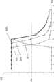
图4示出在干净的光学系统的情况下基于不同的发送功率的接收信号的特性曲线图,FIG. 4 shows a characteristic diagram of the received signal for different transmit powers in the case of a clean optical system,
图5示出在略受污染的光学系统的情况下基于不同的发送功率的接收信号的特性曲线图,FIG. 5 shows a characteristic diagram of the received signal for different transmit powers in the case of a slightly contaminated optical system,
图6示出在严重污染的光学系统的情况下基于不同的发送功率的接收信号的特性曲线图。FIG. 6 shows a characteristic diagram of the received signal for different transmit powers in the case of a heavily soiled optical system.
具体实施方式Detailed ways
在图1中所示的用于监测机器2中的油位的装置由油位调节器1构成。机器2是指例如压缩机。油位调节器1的任务是在缺油时从贮油器6将油补入机器2中。油位调节器1为此具有光学传感器3,该光学传感器3测量机器2中的油高。如果确定缺油,则调节器4打开电磁阀5以将油从贮存器6填充到机器2中。The device shown in FIG. 1 for monitoring the oil level in the
接下来,根据图2和3来进一步阐释光学传感器3的测量原理。光学传感器3具有光学反射体7,该反射体例如构造成玻璃锥体,并且以锥形尖端7a突出到机器2的容器2a内。在容器2a中存在待监测的油9。在与光学反射体7的锥形尖端7a相对的端部7b处,经由光学发送器8将光束10射入光学反射体7中。在待监测的油9的水平在图2中处于光学反射体7的下方之后,在光学反射体7的锥形尖端7a处发生射入的光束10的全反射,以使得被反射的光束在相对的端部7b处从光学反射体达到光学接收器11,并且在那里作为接收信号12被探测到。Next, the measurement principle of the
在分析装置13中将接收信号12与预先给出的电平值相比较。如果油位过低,如图2中所示,则足够高的接收信号12到达接收器11,以使得超过了预先给出的电平值,并且由此识别出缺油。在图3中所示的情况下,突出到容器2a内的光学反射体7的锥形尖端7a位于待监测的油9之内。这使得从发送器8发出的光束10在锥形尖端7a处不反射,而是被折射。因此,仅极少的光或者根本没有光到达光学接收器11。由此分析装置13将接收器11处缺少或者较低的接收信号理解为容器2a中的待监测的油9具有足够的水平(0,足够的油位)。The received
如果光学反射体7的锥形尖端7a被污染,则在缺油的情况下射入的光束10的仅一部分会反射。这意味着随着污染程度增加,接收信号12会越来越弱。在极端情况下,污染程度大到在缺油时在接收器11处产生的接收信号12处于预先给出的电平值之下并且由此分析装置不再能够识别出缺油。If the
借助下面描述的方法可以识别出光学系统或者光学反射体7的锥形尖端7a是否被污染。为此,发送器8与功率调节装置14连接,以使得射入的光束10的发送功率能在最小(例如,10%)发送功率和最大(例如,100%)发送功率之间进行调节。Contamination of the optical system or the
图4涉及干净的光学系统的情况并且示出接收信号12的特性曲线,这些接收信号是基于射入的光束10的不同发送功率(10%、20%和100%)的。在横坐标上以百分比绘出油位的监测范围。在纵坐标上示出在接收器11处产生的接收信号12的电压。油位的监测范围在所示实施例中由光学反射体7的一半直径构成,其中,锥形尖端示出在100%水平下的油位。光学反射体7的下端对应于0%(参见图2)。监测范围因此在光学反射体7的尖端7a和下端之间,并且例如为4毫米。当接收信号12大于预先给出的电平值PW时存在缺油。该电平值在所示实施例中被假定为接收信号的最大电平的一半。可以认识到,接收信号在充足的油位时在所有情况下都是低的,并且所有特性曲线在越来越下降的油位情况下达到最大可能的接收信号(在此为5V)。通过将接收信号与预先给出的电平值PW比较可以识别出缺油,其中,当接收信号超出电平值PW时存在缺油。FIG. 4 relates to the case of a clean optical system and shows the characteristic curves of received
根据不同的特性曲线可以认识到,确认缺油时的油位的实际水平取决于所发出的光束10的发送功率。如果在监测运行中由发送器8发出的光束10以10%的发送功率发出,则特性曲线在约30%油位时与由电平值PW确定的阈值相交。在20%发送功率的情况下,交点处于约40%,并且在发送功率为100%的情况下,在46%的水平下达到缺少的油位。From the different characteristic curves it can be seen that the actual level of the oil level at which the oil starvation is confirmed depends on the transmission power of the emitted
这然后导致经由调节器4和电磁阀5从贮存器6补充油,以使得油位又升高并且接收信号保持在电平值PW之下,直到油位再次下降。This then causes oil to be replenished from the
如果现在在机器的运行中光学系统被污染,则得到图5中所示的曲线。可以看到,基于10%的发送功率的接收信号刚好达到电平值PW以识别出缺油。在图6中示出光学系统被严重污染的情况。可以看到,在监测运行中采用的光束以10%的发送功率不再适于达到电平值PW。因此规定,在监测运行中随着污染增加而提高发送功率,以确保可靠地识别出缺油。If the optical system is now contaminated during operation of the machine, the curve shown in FIG. 5 is obtained. It can be seen that the received signal based on 10% of the transmit power just reaches the level value PW to identify oil starvation. The situation in which the optical system is heavily soiled is shown in FIG. 6 . It can be seen that the beam used in the monitoring operation is no longer suitable for reaching the level value PW with a transmit power of 10%. It is therefore provided that the transmission power is increased in monitoring operation with increasing contamination in order to ensure reliable detection of an oil shortage.
但为此需要确定光学系统的污染程度。这根据本发明这样来进行:一旦识别出缺油就执行下面描述的测试运行。为此,发送器8以最大发送功率(100%)发出第一光束,由此在接收器11处产生第一接收信号。然后,在第一接收信号与第二接收信号之间构成差值,其中,第二接收信号由具有比最大发送功率小的发送功率的光束来产生。在形成两个接收信号的差值的情况下,形成对应的接收信号的最大电平的差值。差值的大小在此表示光学系统的污染程度的度量。But for this it is necessary to determine the degree of contamination of the optical system. This is done according to the invention in that the test run described below is carried out as soon as a lack of oil has been identified. For this purpose, the
作为测试运行中的第二接收信号,适宜的是采用监测运行中确定缺油的接收信号。但也可以设想,在测试运行中为了产生第二接收信号而采用具有较小的发送功率(例如10%)的单独(测试)光束。As the second received signal in the test operation, it is expedient to use the received signal which determines the lack of oil in the monitoring operation. However, it is also conceivable to use a separate (test) beam with a lower transmit power (eg 10%) in the test operation for generating the second received signal.
在图4-6中将发送功率100%时的第一接收信号与发送功率为10%时的第二接收信号之间的差值示出为差值信号D。可以看到,随着污染程度增加,差值信号D的最大电平变得更低。因此,差值信号的最大电平在根据图4的干净的光学系统的情况下为约4.7V,而在稍被污染的光学系统的情况下降低到3.2V,并且在严重污染的光学系统的情况下仅还为2.3V。由具有射入的光束的不同发送功率的接收信号产生的差值信号D因此可被视作光学系统的污染程度的度量。为了节约运行成本,有意义的是从发送器8发出的光束10以尽可能低的发送功率来发出。该发送功率但是必须足够高以使得可靠地识别出缺油。借助上述测试方法,现在可根据第一接收信号和第二接收信号之间的差值的大小来提高发送功率。因此,图5中的情况示出了必须提高初始的10%发送功率的最迟时刻。在图5中所示的污染程度下,针对缺油的可靠识别,20%的发送功率就够了。The difference between the first received signal at 100% transmit power and the second received signal at 10% transmit power is shown as difference signal D in FIGS. 4-6 . It can be seen that as the degree of contamination increases, the maximum level of the difference signal D becomes lower. Therefore, the maximum level of the difference signal is about 4.7V in the case of a clean optical system according to Fig. 4, and decreases to 3.2V in the case of a slightly soiled optical system, and in the case of a heavily soiled optical system The case is also only 2.3V. The difference signal D resulting from the received signals with different transmit powers of the incoming light beam can thus be regarded as a measure of the degree of contamination of the optical system. In order to save operating costs, it makes sense to emit the
以此方式,随着污染加剧,发送功率继续越来越高。在严重污染的情况下,如在根据图6的示图中所示,当光束在监测运行中以100%的发送功率被射入时还是能确定缺油的。这也是光学系统、特别是光学反射体7的锥形尖端7a要进行清洁的最晚时刻。例如,通过如下方式来确定清洁光学系统的正确时刻:第一接收信号和第二接收信号之间的差值低于预先给出的值。In this way, the transmit power continues to get higher and higher as the pollution increases. In the case of severe contamination, as shown in the illustration according to FIG. 6 , a lack of oil can still be determined when the light beam is injected with 100% transmission power in monitoring operation. This is also the latest time for cleaning of the optical system, especially the tapered
识别出缺油时总是还按常规地执行测试运行。可选的是,当在监测运行中没有测得缺油、但自从上一次确定的缺油起已过去了一段确定的时间段时,也可以进行测试运行。因此例如可以想象,光学系统已在接通机器时被严重污染,以使得所采用的发送功率不足以在缺油时产生足够高的接收信号。但如果按照惯例在确定的一时间段(例如,30分钟或者60分钟)之后执行测试运行,则可以可靠地识别出这种污染。When a lack of oil is detected, a test run is always carried out as usual. Optionally, a test run can also be performed when no oil starvation is detected in the monitoring run, but a defined period of time has elapsed since the last identified oil starvation. Thus, for example, it is conceivable that the optical system is already heavily soiled when the machine is switched on, so that the transmit power used is not sufficient to generate a sufficiently high received signal in the event of a lack of oil. However, such contamination can be reliably identified if a test run is routinely performed after a determined period of time (eg, 30 minutes or 60 minutes).
在运行机器、例如特别是压缩机时,总是必须补充油是常见的。在此,可以获悉两次补充油之间的时间间隔,并且当从上一次补充油起的时间间隔与过去记录的时间间隔相比超过预先给出的程度时,可以进行测试运行。在此特别是建议,通过例如考虑最近五个时间间隔来对过去记录的时间间隔取平均。It is not uncommon for the oil to always have to be replenished when running machines, such as compressors in particular. Here, the time interval between two oil replenishments can be known, and a test run can be carried out when the time interval since the last oil replenishment exceeds the previously recorded time interval by a predetermined extent. In particular, it is proposed here to average the time intervals recorded in the past by, for example, taking into account the last five time intervals.
Claims (9)
Translated fromChineseApplications Claiming Priority (2)
| Application Number | Priority Date | Filing Date | Title |
|---|---|---|---|
| DE102016115228.5ADE102016115228B4 (en) | 2016-08-17 | 2016-08-17 | Method and device for monitoring an oil level in a machine |
| DE102016115228.5 | 2016-08-17 |
Publications (2)
| Publication Number | Publication Date |
|---|---|
| CN107764368A CN107764368A (en) | 2018-03-06 |
| CN107764368Btrue CN107764368B (en) | 2020-08-07 |
Family
ID=61082603
Family Applications (1)
| Application Number | Title | Priority Date | Filing Date |
|---|---|---|---|
| CN201710700805.0AExpired - Fee RelatedCN107764368B (en) | 2016-08-17 | 2017-08-16 | Method and apparatus for monitoring oil level in a machine |
Country Status (4)
| Country | Link |
|---|---|
| US (1) | US10151617B2 (en) |
| CN (1) | CN107764368B (en) |
| DE (1) | DE102016115228B4 (en) |
| IT (1) | IT201700090110A1 (en) |
Families Citing this family (4)
| Publication number | Priority date | Publication date | Assignee | Title |
|---|---|---|---|---|
| ITUA20164350A1 (en)* | 2016-06-14 | 2017-12-14 | Emak Spa | Cutting tool |
| JP6822897B2 (en)* | 2017-05-19 | 2021-01-27 | サンデン・リテールシステム株式会社 | Beverage supply device |
| US10654450B2 (en)* | 2018-09-11 | 2020-05-19 | Rockwell Automation Technologies, Inc. | Droplet sensor |
| DE102021104356A1 (en) | 2021-02-24 | 2022-08-25 | Kriwan Industrie-Elektronik Gmbh | Gauge for fluid level monitoring |
Citations (5)
| Publication number | Priority date | Publication date | Assignee | Title |
|---|---|---|---|---|
| US4898462A (en)* | 1987-02-26 | 1990-02-06 | Nippondenso Co., Ltd. | Device for detecting a transmissivity of a substance |
| US5005005A (en)* | 1986-03-10 | 1991-04-02 | Brossia Charles E | Fiber optic probe system |
| CN103826756A (en)* | 2011-09-19 | 2014-05-28 | 皇家飞利浦有限公司 | Analysis and control of aerosol output |
| CN105300862A (en)* | 2015-11-13 | 2016-02-03 | 金陵科技学院 | Cloud processing-based vehicle-mounted mobile atmosphere particle pollutant environment detection method and system |
| WO2016067228A1 (en)* | 2014-10-30 | 2016-05-06 | Univerza V Ljubljani, Fakulteta Za Elektrotehniko | Sensor for measuring surface moisture on an uneven surface |
Family Cites Families (6)
| Publication number | Priority date | Publication date | Assignee | Title |
|---|---|---|---|---|
| GB2036326B (en) | 1978-10-20 | 1983-08-17 | Klinger Ag | Liquid level sensor |
| US5452076A (en) | 1993-09-29 | 1995-09-19 | Optiguard, Inc. | Fluid detection system |
| KR100303161B1 (en)* | 1998-08-31 | 2001-10-19 | 장철주 | An on-line device for measuring quantitative particle contamination in lubricating oils |
| DE19936574A1 (en) | 1999-08-03 | 2001-02-08 | Schrodt Stephan | Optical sensor for continuous measurement and monitoring of filling level of fluid in tank based on change in refractive index of an optical fibre at point where it is wetted by fluid |
| DE10201767A1 (en) | 2001-11-30 | 2003-06-12 | Mecoswiss Mechanische Componen | Level sensor for a household appliance, such as a washing machine or dishwasher, has a simple optoelectronic detector arrangement that can be used with containers of varying size and liquid or material cleaning agents |
| US9105181B2 (en)* | 2006-06-08 | 2015-08-11 | Mueller International, Llc | Systems and methods for generating power through the flow of water |
- 2016
- 2016-08-17DEDE102016115228.5Apatent/DE102016115228B4/ennot_activeExpired - Fee Related
- 2017
- 2017-08-03ITIT102017000090110Apatent/IT201700090110A1/enunknown
- 2017-08-09USUS15/672,372patent/US10151617B2/ennot_activeExpired - Fee Related
- 2017-08-16CNCN201710700805.0Apatent/CN107764368B/ennot_activeExpired - Fee Related
Patent Citations (5)
| Publication number | Priority date | Publication date | Assignee | Title |
|---|---|---|---|---|
| US5005005A (en)* | 1986-03-10 | 1991-04-02 | Brossia Charles E | Fiber optic probe system |
| US4898462A (en)* | 1987-02-26 | 1990-02-06 | Nippondenso Co., Ltd. | Device for detecting a transmissivity of a substance |
| CN103826756A (en)* | 2011-09-19 | 2014-05-28 | 皇家飞利浦有限公司 | Analysis and control of aerosol output |
| WO2016067228A1 (en)* | 2014-10-30 | 2016-05-06 | Univerza V Ljubljani, Fakulteta Za Elektrotehniko | Sensor for measuring surface moisture on an uneven surface |
| CN105300862A (en)* | 2015-11-13 | 2016-02-03 | 金陵科技学院 | Cloud processing-based vehicle-mounted mobile atmosphere particle pollutant environment detection method and system |
Non-Patent Citations (1)
| Title |
|---|
| 可调谐二极管激光吸收光谱技术及其在大气质量监测中的应用;董凤忠;《量子电子学报》;20050630;第22卷(第3期);第315-324页* |
Also Published As
| Publication number | Publication date |
|---|---|
| US10151617B2 (en) | 2018-12-11 |
| DE102016115228B4 (en) | 2021-12-16 |
| DE102016115228A1 (en) | 2018-02-22 |
| IT201700090110A1 (en) | 2019-02-03 |
| CN107764368A (en) | 2018-03-06 |
| US20180052034A1 (en) | 2018-02-22 |
Similar Documents
| Publication | Publication Date | Title |
|---|---|---|
| CN107764368B (en) | Method and apparatus for monitoring oil level in a machine | |
| KR101724165B1 (en) | Turbidity sensor | |
| US20040139788A1 (en) | Tank leak detection and reporting system | |
| US10626863B2 (en) | Pump station monitoring system and method | |
| US10927829B2 (en) | Pump monitoring method | |
| US7317993B2 (en) | Fluid detector recognizing foam and surge conditions | |
| US10416021B2 (en) | Method for fill level measurement using the travel time principle | |
| US20150241263A1 (en) | Sensor for Determining a Filling Level | |
| CN109786278B (en) | Intelligent detection and processing method for needle point of probe card | |
| CN108843972B (en) | Fuel oil delivery system, exhaust device, fuel oil delivery method and controller | |
| CN111142392B (en) | Food processor and control method thereof | |
| CN1988838A (en) | Method used to calibrate the sensor | |
| US20230119267A1 (en) | System for Providing Lubrication to a Machine | |
| JP5468156B2 (en) | Gas flow rate change judgment device | |
| US20240017960A1 (en) | Method and controller for evaluating information about a current location of a car in a shaft of an elevator | |
| JP4149963B2 (en) | Magnetostrictive level gauge | |
| CN115046615A (en) | Ultrasonic water dispenser and fault detection method and processor thereof | |
| KR101713723B1 (en) | Detection system of deterioration of a fuel pressure sensor and detection method | |
| KR101045322B1 (en) | Oil mist detection device having a floodlight contamination detection unit and a floodlight contamination detection method of the oil mist detection device | |
| JP7630612B2 (en) | Method for monitoring the oil level of an oil-lubricated compressor, an oil level monitoring system for carrying out said method, and a compressor system equipped with such an oil level monitoring system | |
| KR101547631B1 (en) | Method and apparatus for detecting low water level in heatpump boiler system | |
| WO2015074726A1 (en) | Method for lubricating a machine part and machine arrangement | |
| RU2627984C1 (en) | Device and method for controlling wireless sensor performability | |
| JPS5810187A (en) | Apparatus for judging capacity of feed water pump | |
| KR101266787B1 (en) | Circuit and method for controlling brush of ultrasonic sensor and ultrasonic sludge level meter including the circuit |
Legal Events
| Date | Code | Title | Description |
|---|---|---|---|
| PB01 | Publication | ||
| PB01 | Publication | ||
| SE01 | Entry into force of request for substantive examination | ||
| SE01 | Entry into force of request for substantive examination | ||
| GR01 | Patent grant | ||
| GR01 | Patent grant | ||
| CF01 | Termination of patent right due to non-payment of annual fee | Granted publication date:20200807 | |
| CF01 | Termination of patent right due to non-payment of annual fee |