CN107743365B - Electronic smoking device - Google Patents
Electronic smoking deviceDownload PDFInfo
- Publication number
- CN107743365B CN107743365BCN201680034731.5ACN201680034731ACN107743365BCN 107743365 BCN107743365 BCN 107743365BCN 201680034731 ACN201680034731 ACN 201680034731ACN 107743365 BCN107743365 BCN 107743365B
- Authority
- CN
- China
- Prior art keywords
- heating element
- receiving unit
- electronic smoking
- smoking device
- solid
- Prior art date
- Legal status (The legal status is an assumption and is not a legal conclusion. Google has not performed a legal analysis and makes no representation as to the accuracy of the status listed.)
- Expired - Fee Related
Links
Images


Classifications
- A—HUMAN NECESSITIES
- A61—MEDICAL OR VETERINARY SCIENCE; HYGIENE
- A61M—DEVICES FOR INTRODUCING MEDIA INTO, OR ONTO, THE BODY; DEVICES FOR TRANSDUCING BODY MEDIA OR FOR TAKING MEDIA FROM THE BODY; DEVICES FOR PRODUCING OR ENDING SLEEP OR STUPOR
- A61M15/00—Inhalators
- A61M15/06—Inhaling appliances shaped like cigars, cigarettes or pipes
- A—HUMAN NECESSITIES
- A24—TOBACCO; CIGARS; CIGARETTES; SIMULATED SMOKING DEVICES; SMOKERS' REQUISITES
- A24F—SMOKERS' REQUISITES; MATCH BOXES; SIMULATED SMOKING DEVICES
- A24F40/00—Electrically operated smoking devices; Component parts thereof; Manufacture thereof; Maintenance or testing thereof; Charging means specially adapted therefor
- A24F40/40—Constructional details, e.g. connection of cartridges and battery parts
- A24F40/42—Cartridges or containers for inhalable precursors
- A—HUMAN NECESSITIES
- A24—TOBACCO; CIGARS; CIGARETTES; SIMULATED SMOKING DEVICES; SMOKERS' REQUISITES
- A24F—SMOKERS' REQUISITES; MATCH BOXES; SIMULATED SMOKING DEVICES
- A24F40/00—Electrically operated smoking devices; Component parts thereof; Manufacture thereof; Maintenance or testing thereof; Charging means specially adapted therefor
- A24F40/40—Constructional details, e.g. connection of cartridges and battery parts
- A24F40/46—Shape or structure of electric heating means
- A—HUMAN NECESSITIES
- A61—MEDICAL OR VETERINARY SCIENCE; HYGIENE
- A61M—DEVICES FOR INTRODUCING MEDIA INTO, OR ONTO, THE BODY; DEVICES FOR TRANSDUCING BODY MEDIA OR FOR TAKING MEDIA FROM THE BODY; DEVICES FOR PRODUCING OR ENDING SLEEP OR STUPOR
- A61M11/00—Sprayers or atomisers specially adapted for therapeutic purposes
- A61M11/04—Sprayers or atomisers specially adapted for therapeutic purposes operated by the vapour pressure of the liquid to be sprayed or atomised
- A61M11/041—Sprayers or atomisers specially adapted for therapeutic purposes operated by the vapour pressure of the liquid to be sprayed or atomised using heaters
- A61M11/042—Sprayers or atomisers specially adapted for therapeutic purposes operated by the vapour pressure of the liquid to be sprayed or atomised using heaters electrical
- H—ELECTRICITY
- H05—ELECTRIC TECHNIQUES NOT OTHERWISE PROVIDED FOR
- H05B—ELECTRIC HEATING; ELECTRIC LIGHT SOURCES NOT OTHERWISE PROVIDED FOR; CIRCUIT ARRANGEMENTS FOR ELECTRIC LIGHT SOURCES, IN GENERAL
- H05B3/00—Ohmic-resistance heating
- H05B3/40—Heating elements having the shape of rods or tubes
- H05B3/42—Heating elements having the shape of rods or tubes non-flexible
- H05B3/44—Heating elements having the shape of rods or tubes non-flexible heating conductor arranged within rods or tubes of insulating material
- A—HUMAN NECESSITIES
- A24—TOBACCO; CIGARS; CIGARETTES; SIMULATED SMOKING DEVICES; SMOKERS' REQUISITES
- A24F—SMOKERS' REQUISITES; MATCH BOXES; SIMULATED SMOKING DEVICES
- A24F40/00—Electrically operated smoking devices; Component parts thereof; Manufacture thereof; Maintenance or testing thereof; Charging means specially adapted therefor
- A24F40/20—Devices using solid inhalable precursors
- A—HUMAN NECESSITIES
- A61—MEDICAL OR VETERINARY SCIENCE; HYGIENE
- A61M—DEVICES FOR INTRODUCING MEDIA INTO, OR ONTO, THE BODY; DEVICES FOR TRANSDUCING BODY MEDIA OR FOR TAKING MEDIA FROM THE BODY; DEVICES FOR PRODUCING OR ENDING SLEEP OR STUPOR
- A61M16/00—Devices for influencing the respiratory system of patients by gas treatment, e.g. ventilators; Tracheal tubes
- A61M16/0003—Accessories therefor, e.g. sensors, vibrators, negative pressure
- A61M2016/0015—Accessories therefor, e.g. sensors, vibrators, negative pressure inhalation detectors
- A61M2016/0018—Accessories therefor, e.g. sensors, vibrators, negative pressure inhalation detectors electrical
- A61M2016/0024—Accessories therefor, e.g. sensors, vibrators, negative pressure inhalation detectors electrical with an on-off output signal, e.g. from a switch
- A—HUMAN NECESSITIES
- A61—MEDICAL OR VETERINARY SCIENCE; HYGIENE
- A61M—DEVICES FOR INTRODUCING MEDIA INTO, OR ONTO, THE BODY; DEVICES FOR TRANSDUCING BODY MEDIA OR FOR TAKING MEDIA FROM THE BODY; DEVICES FOR PRODUCING OR ENDING SLEEP OR STUPOR
- A61M16/00—Devices for influencing the respiratory system of patients by gas treatment, e.g. ventilators; Tracheal tubes
- A61M16/0003—Accessories therefor, e.g. sensors, vibrators, negative pressure
- A61M2016/003—Accessories therefor, e.g. sensors, vibrators, negative pressure with a flowmeter
- A61M2016/0033—Accessories therefor, e.g. sensors, vibrators, negative pressure with a flowmeter electrical
- A61M2016/0039—Accessories therefor, e.g. sensors, vibrators, negative pressure with a flowmeter electrical in the inspiratory circuit
- A—HUMAN NECESSITIES
- A61—MEDICAL OR VETERINARY SCIENCE; HYGIENE
- A61M—DEVICES FOR INTRODUCING MEDIA INTO, OR ONTO, THE BODY; DEVICES FOR TRANSDUCING BODY MEDIA OR FOR TAKING MEDIA FROM THE BODY; DEVICES FOR PRODUCING OR ENDING SLEEP OR STUPOR
- A61M2205/00—General characteristics of the apparatus
- A61M2205/33—Controlling, regulating or measuring
- A61M2205/3375—Acoustical, e.g. ultrasonic, measuring means
- A—HUMAN NECESSITIES
- A61—MEDICAL OR VETERINARY SCIENCE; HYGIENE
- A61M—DEVICES FOR INTRODUCING MEDIA INTO, OR ONTO, THE BODY; DEVICES FOR TRANSDUCING BODY MEDIA OR FOR TAKING MEDIA FROM THE BODY; DEVICES FOR PRODUCING OR ENDING SLEEP OR STUPOR
- A61M2205/00—General characteristics of the apparatus
- A61M2205/36—General characteristics of the apparatus related to heating or cooling
- A61M2205/3653—General characteristics of the apparatus related to heating or cooling by Joule effect, i.e. electric resistance
- A—HUMAN NECESSITIES
- A61—MEDICAL OR VETERINARY SCIENCE; HYGIENE
- A61M—DEVICES FOR INTRODUCING MEDIA INTO, OR ONTO, THE BODY; DEVICES FOR TRANSDUCING BODY MEDIA OR FOR TAKING MEDIA FROM THE BODY; DEVICES FOR PRODUCING OR ENDING SLEEP OR STUPOR
- A61M2205/00—General characteristics of the apparatus
- A61M2205/58—Means for facilitating use, e.g. by people with impaired vision
- A61M2205/583—Means for facilitating use, e.g. by people with impaired vision by visual feedback
- A61M2205/584—Means for facilitating use, e.g. by people with impaired vision by visual feedback having a color code
- A—HUMAN NECESSITIES
- A61—MEDICAL OR VETERINARY SCIENCE; HYGIENE
- A61M—DEVICES FOR INTRODUCING MEDIA INTO, OR ONTO, THE BODY; DEVICES FOR TRANSDUCING BODY MEDIA OR FOR TAKING MEDIA FROM THE BODY; DEVICES FOR PRODUCING OR ENDING SLEEP OR STUPOR
- A61M2205/00—General characteristics of the apparatus
- A61M2205/82—Internal energy supply devices
- A61M2205/8206—Internal energy supply devices battery-operated
Landscapes
- Health & Medical Sciences (AREA)
- Engineering & Computer Science (AREA)
- Anesthesiology (AREA)
- Biomedical Technology (AREA)
- Heart & Thoracic Surgery (AREA)
- Hematology (AREA)
- Life Sciences & Earth Sciences (AREA)
- Animal Behavior & Ethology (AREA)
- General Health & Medical Sciences (AREA)
- Public Health (AREA)
- Veterinary Medicine (AREA)
- Bioinformatics & Cheminformatics (AREA)
- Pulmonology (AREA)
- Manufacture Of Tobacco Products (AREA)
- Resistance Heating (AREA)
Abstract
Translated fromChinese
Description
Translated fromChinese技术领域technical field
本发明总体上涉及电子吸烟装置,尤其涉及电子烟。The present invention relates generally to electronic smoking devices, and more particularly to electronic cigarettes.
背景技术Background technique
诸如电子烟(e-cigarette)的电子吸烟装置通常具有容纳电源(例如,一次性电池或可充电电池)的壳体以及可电操作的雾化器。雾化器蒸发或雾化由储存器供应的烟液,并且将经蒸发或雾化的烟液作为气雾提供。控制电路控制雾化器的激活。在许多电子烟中,电子吸烟装置具有检测用户在设备上抽吸(例如,通过感测负压或通过该装置的空气流动模式)的气流传感器。气流传感器指示或表示到控制电路的抽吸。可选地,按钮可以被用来启动电子吸烟装置以产生对香料的抽吸。当检测到抽吸时,控制电路为雾化器供电从而产生蒸发成气雾的烟液。Electronic smoking devices such as electronic cigarettes (e-cigarettes) typically have a housing that houses a power source (eg, a disposable or rechargeable battery) and an electrically operable atomizer. The atomizer vaporizes or atomizes the e-liquid supplied by the reservoir and provides the vaporized or atomized e-liquid as an aerosol. A control circuit controls the activation of the atomizer. In many electronic cigarettes, electronic smoking devices have airflow sensors that detect a user's puff on the device (eg, by sensing negative pressure or air flow patterns through the device). The airflow sensor indicates or indicates suction to the control circuit. Optionally, a button may be used to activate the electronic smoking device to produce a puff of flavor. When a puff is detected, the control circuit powers the nebulizer so as to generate the liquid smoke that evaporates into an aerosol.
最近,允许消耗固体吸烟材料的电子吸烟装置占据越来越多的市场。固体吸烟材料通常由可以包括尼古丁的蜡或凝胶,和/或其它调味或非调味组份组成。在电子吸烟装置中,固体吸烟材料首先被液化,之后被雾化器雾化。为了给电子吸烟装置填充固体吸烟材料,本领域中已知的大多数装置要求使用者打开电子吸烟装置,并使用诸如小铲或小勺的工具来添加固体吸烟材料。这样的步骤复杂、费时,并且可能不必要地干扰对装置的抽吸乐趣。More recently, electronic smoking devices that allow for the consumption of solid smoking materials have taken up more and more of the market. Solid smoking materials typically consist of waxes or gels, which may include nicotine, and/or other flavored or non-flavored components. In electronic smoking devices, the solid smoking material is first liquefied and then atomized by the atomizer. To fill an electronic smoking device with solid smoking material, most devices known in the art require the user to open the electronic smoking device and use a tool such as a spatula or spoon to add the solid smoking material. Such steps are complex, time consuming, and may unnecessarily interfere with the enjoyment of pumping the device.
发明内容SUMMARY OF THE INVENTION
根据本发明的一个方面提供了一种电子吸烟装置,其包括壳体和用于接收适于产生气雾的固体吸烟材料的接收单元。电子吸烟装置还包括邻近该接收单元设置的主加热元件。主加热元件适于液化固体吸烟材料以及雾化经液化的固体吸烟材料。此外,电子吸烟装置包括用于迫使添加到接收单元中的固体吸烟材料朝向主加热元件的定位元件,其中,接收单元、主加热元件和定位元件设置在壳体内。According to one aspect of the present invention there is provided an electronic smoking device comprising a housing and a receiving unit for receiving solid smoking material adapted to generate an aerosol. The electronic smoking device also includes a primary heating element disposed adjacent the receiving unit. The primary heating element is adapted to liquefy solid smoking material and to aerosolize liquefied solid smoking material. Furthermore, the electronic smoking device comprises a positioning element for forcing the solid smoking material added into the receiving unit towards the main heating element, wherein the receiving unit, the main heating element and the positioning element are arranged within the housing.
这种电子吸烟装置的优点是改善了对固体吸烟材料的处理。旨在用固体吸烟材料填充电子吸烟装置的用户可以容易地将固体吸烟材料手动地添加到接收单元中,而不需要其他的工具。此后,定位元件迫使添加到接收单元中的固体吸烟材料朝向主加热元件,将固体材料定位在固定位置以产生气雾,并降低固体吸烟材料的位置需要被调整或替换的频率。An advantage of such an electronic smoking device is improved handling of solid smoking materials. A user aiming to fill an electronic smoking device with solid smoking material can easily manually add the solid smoking material to the receiving unit without the need for additional tools. Thereafter, the positioning element forces the solid smoking material added to the receiving unit towards the main heating element, positioning the solid material in a fixed position to generate the aerosol and reducing the frequency with which the position of the solid smoking material needs to be adjusted or replaced.
结合以下参照附图说明的对示例性实施例的描述,本发明的特性、特征和优点以及如上所述获得它们的方式将变得更加显然并且更加清楚地被理解。The nature, features, and advantages of the present invention, and the manner in which they are obtained as described above, will become more apparent and more clearly understood in conjunction with the following description of exemplary embodiments with reference to the accompanying drawings.
附图说明Description of drawings
在附图中,相同的元件标号在每个视图中指示相同的元件:In the drawings, like element numbers refer to like elements throughout each view:
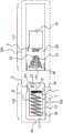
图1是根据本发明的电子吸烟装置的第一实施例的横截面示意图;1 is a schematic cross-sectional view of a first embodiment of an electronic smoking device according to the present invention;
图2a是根据本发明的电子吸烟装置的第二实施例的横截面示意图,Figure 2a is a schematic cross-sectional view of a second embodiment of an electronic smoking device according to the present invention,
图2b和图2c是根据本发明的预先填充有固体吸烟材料的电子吸烟装置的第二实施例的横截面示意图,Figures 2b and 2c are schematic cross-sectional views of a second embodiment of an electronic smoking device prefilled with solid smoking material according to the present invention,
图3是根据本发明的处于装配和激活状态的电子吸烟装置的第二实施例的横截面示意图,Figure 3 is a schematic cross-sectional view of a second embodiment of an electronic smoking device according to the present invention in an assembled and activated state,
图4是根据本发明的电子吸烟装置的第三实施例的示意图,Figure 4 is a schematic diagram of a third embodiment of the electronic smoking device according to the present invention,
图5是根据本发明的电子吸烟装置的第四实施例的示意图,5 is a schematic diagram of a fourth embodiment of an electronic smoking device according to the present invention,
图6是根据本发明的电子吸烟装置的第五实施例的示意图,以及6 is a schematic diagram of a fifth embodiment of an electronic smoking device according to the present invention, and
图7是根据本发明的电子吸烟装置的第六实施例的示意图。Figure 7 is a schematic diagram of a sixth embodiment of an electronic smoking device according to the present invention.
附图标记列表List of reference signs
1、200、300、400、500 电子吸烟装置1, 200, 300, 400, 500 electronic smoking devices
2、102、202、302 壳体2, 102, 202, 302 housing
3 接收单元3 Receiver unit
4 固体吸烟材料4 Solid Smoking Materials
5、205、305 主加热元件5, 205, 305 main heating element
6 装置6 devices
7 中空体7 Hollow body
8 开口8 openings
9 边缘9 edge
10 侧壁10 side walls
11 后壁11 Back wall
12 多孔元件12 Porous elements
13 开口13 openings
16、116 烟嘴部分16, 116 cigarette holder part
17、117、217、317 主体17, 117, 217, 317 Main body
18 端盖18 End caps
19 电池19 Batteries
20 发光二极管(LED)20 Light Emitting Diodes (LEDs)
21 控制电路21 Control circuit
22 气流传感器22 Airflow sensor
23 雾化器23 Atomizers
24 空气吸入口24 Air intake
25 空气入口25 Air inlet
26 可移动的止动件26 Removable stops
27 活塞27 Pistons
28 弹簧28 spring
29 加热线圈29 Heating coil
33 第二开口33 Second opening
35 外螺纹35 external thread
36 内螺纹36 Internal thread
207 空隙207 void
230 螺旋形的加热元件230 Helical Heating Elements
306 可加热的穿透装置306 Heatable Penetrator
414、514 次加热元件414, 514 heating elements
415 金属板415 sheet metal
532 第二加热线圈532 Second heating coil
具体实施方式Detailed ways
图1示出了根据本发明的电子吸烟装置1的第一实施例的横截面示意图。在该第一实施例中,电子吸烟装置1被实现为电子烟1,其包括具有主体17和烟嘴部分16的圆柱形壳体2。主体17和烟嘴部分16一起形成圆柱形管,该圆柱形管与常规香烟的大小和形状大致相同。然而,在其他实施例中,电子吸烟装置1可以被实现为比传统的香烟更大,并且可以被实现为具有与常规香烟的形状不同的形状。Figure 1 shows a schematic cross-sectional view of a first embodiment of an electronic smoking device 1 according to the present invention. In this first embodiment, the electronic smoking device 1 is implemented as an electronic cigarette 1 comprising a cylindrical housing 2 having a
主体17和烟嘴部分16通常由钢或硬质塑料制成,并且用于提供壳体2以容纳电子吸烟装置1的操作元件。在电子吸烟设备1的该实施例中,主体17和烟嘴部分16可以被配置成通过摩擦推入配合(friction push fit)的方式装配在一起。可选地,在一些电子吸烟装置1中,主体17和烟嘴部分16可以是单个一体成型管的部分。The
端盖18设置在主体17远离烟嘴部分16的端部,密封主体17的这一端部。端盖18通常由半透明塑料制成,但不限于此。An
电池19设置在由主体17包围的中央腔内。发光二极管(LED)20、控制电路21和气流传感器22也被容纳在由主体17限定的中央腔内。电池19电连接到LED 20和控制电路21,并且气流传感器22被连接到控制电路21。在该示例中,LED20设置在主体17邻近端盖18的一端,并且控制电路21和气流传感器22设置在邻近烟嘴部分16的电池19另一端的中央腔中。The
气流传感器22作为抽吸检测器,用于检测使用者对电子吸烟装置1的烟嘴部分16的抽吸或吮吸。气流传感器24可以是用于检测气流或气压变化的任何合适的传感器,诸如麦克风开关,该麦克风开关包括根据气压的变化发生位移的可变形膜。The airflow sensor 22 acts as a puff detector for detecting puffing or sucking of the
控制电路21还连接到雾化器23,雾化器23在该示例性实施例中包括主加热元件5,该主加热元件5示例性地实现为加热线圈29,该加热线圈29延伸穿过电子吸烟装置1的烟嘴部分16的直径的至少一部分。烟嘴部分16和主加热元件5的直径的尺寸使得主加热元件5不完全阻塞烟嘴部分16内的气流通道,而是在加热线圈29的任一侧设置有使空气流过主加热元件5的气隙。空气吸入口24设置在烟嘴部分16远离电子吸烟装置1的主体17的端部,并且一对空气入口25设置在壳体2中邻近气流传感器22的主体17和烟嘴部分16之间的相交处。在其他实施例中,空气入口25可以被设置在不同位置,和/或单个空气入口可以被使用,或者可选地,壳体2可以不是气密的并且在没有任何明确的空气入口时空气可以进入壳体。The control circuit 21 is also connected to the
在本发明的第一实施例中,电子吸烟装置1还包括用于接收适于产生气雾的固体吸烟材料的接收单元3。接收单元3设置在电子吸烟装置1的烟嘴部分16内,并且包括具有开口端8的中空体7,中空体7具有边缘9、侧壁10和后壁11,该侧壁10从边缘9延伸。在第一实施例中,接收单元3大体上具有经由后壁11封闭的管的形状。开口端8和边缘9设置在接收单元3与后壁11相对的端部,面对电子吸烟装置1的主加热元件5,并且接收单元的后壁11面对在烟嘴部分16远离主体17的端部处的空气吸入口24。但是,接收单元3的外形不受上述形状的限制。接收单元3作为用于接收适于产生气雾的固体吸烟材料的容器或接收器。在一些设计中,固体吸烟材料可选地可以直接被容纳在壳体内而不使用单独的接收单元。In the first embodiment of the present invention, the electronic smoking device 1 further comprises a receiving
主加热元件5邻近接收单元3设置,并且适于液化固体吸烟材料以及雾化当时经液化的固体吸烟材料。电子吸烟装置1还包括用于迫使添加到接收单元3中的固体吸烟材料朝向主加热元件5的定位元件6,其中,接收单元3、主加热元件5和定位元件6设置在壳体2内。The
在该第一实施例中,定位元件6示例性地被实现为机械定位元件,该机械定位元件包括连接到弹簧28的活塞27。但是,包括适于迫使添加到接收单元3的固体吸烟材料朝向主加热元件5的其他定位元件6的,根据本发明的电子吸烟装置1的实施例也是可以实现的。例如,这种定位元件6可以是液压装置、机电装置或者诸如不带有活塞27的弹簧28的其他机械元件或单元等。在一些实施例中,定位元件6是接收单元3的部分。在这样的实施例中,定位元件6的形状与接收单元3的形状相对应。仅将弹簧28作为定位元件6使用是合算的,并且可靠地用于将电子吸烟装置中的固体吸烟材料移动至该固体吸烟材料可以液化和雾化的位置。In this first embodiment, the
根据本发明的电子吸烟装置1被设计用于消耗固体吸烟材料。这种固体吸烟材料可以被实现为凝胶和/或蜡,或者可以至少由部分这种凝胶和/或蜡制成。凝胶和/或蜡示例性地可以被压成块或类似物。固体吸烟材料可以是任何适于雾化,能被嵌入载体基质或介质中的材料。此外,固体吸烟材料可以包括尼古丁。另外,可以向固体吸烟材料中加入调味材料,例如酯,诸如乙酸异戊酯、乙酸芳樟酯、丙酸异戊酯和丁酸芳樟酯等,或者例如植物精油的天然精油,诸如留兰香、薄荷、桂皮、茉莉等,或者例如动物精油的天然精油,诸如麝、琥珀、麝猫和蓖麻等,或者简单的调味材料,诸如茴香脑、柠檬烯、芳樟醇和丁子香酚等,或者亲水性香料成分,诸如烟叶提取物,或者天然植物调味材料,诸如甘草汁、圣约翰麦芽汁、李子提取物和桃子提取物等,或者酸,诸如苹果酸、酒石酸和柠檬酸等,或者糖,诸如葡萄糖、果糖和异构糖等,或者多元醇,诸如丙二醇、丙三醇和山梨醇等。也可以将如上所述的不同的调味材料组合成新的调味材料。此外,可以将任何香料吸附到固体吸烟材料上,并且可以将该固体吸烟材料用作根据本发明的电子吸烟装置1内的调味材料。The electronic smoking device 1 according to the present invention is designed to consume solid smoking material. Such solid smoking material may be implemented as a gel and/or wax, or may be made at least in part from such a gel and/or wax. The gel and/or wax can illustratively be pressed into blocks or the like. The solid smoking material can be any material suitable for aerosolization that can be embedded in a carrier matrix or medium. Additionally, the solid smoking material may include nicotine. Additionally, flavoring materials such as esters such as isoamyl acetate, linalyl acetate, isoamyl propionate, linalyl butyrate, etc., or natural essential oils such as plant essential oils such as spearmint, may be added to the solid smoking material Incense, peppermint, cinnamon, jasmine, etc., or natural essential oils such as animal essential oils, such as musk, amber, civet, castor, etc., or simple flavoring materials, such as anethole, limonene, linalool, eugenol, etc., or Hydrophilic flavor ingredients, such as tobacco leaf extract, or natural plant flavoring materials, such as licorice juice, St. John's wort, plum extract, peach extract, etc., or acids, such as malic acid, tartaric acid, and citric acid, etc., or sugars , such as glucose, fructose, and isomerized sugars, or polyols such as propylene glycol, glycerol, and sorbitol. It is also possible to combine different seasoning materials as described above into new seasoning materials. Furthermore, any flavourant can be adsorbed onto the solid smoking material and the solid smoking material can be used as flavouring material in the electronic smoking device 1 according to the present invention.
固体吸烟材料不含任何需要燃烧的组份。此外,固体吸烟材料不包括烟草纤维或复原烟草薄片,特别是用丙二醇和/或丙三醇浸渍的烟草纤维或复原烟草薄片。在该第一实施例中,固体吸烟材料不含除尼古丁之外的任何烟草或烟草衍生材料。但是,固体吸烟材料可以包括作为蜡或凝胶的丙二醇和丙三醇。Solid smoking materials do not contain any components that require combustion. Furthermore, solid smoking materials do not include tobacco fibers or reconstituted tobacco sheets, particularly tobacco fibers or reconstituted tobacco sheets impregnated with propylene glycol and/or glycerol. In this first embodiment, the solid smoking material does not contain any tobacco or tobacco-derived material other than nicotine. However, solid smoking materials may include propylene glycol and glycerol as waxes or gels.
为了将固体吸烟材料装入电子吸烟装置1,将其中设有接收单元3的吸嘴部分16从电子吸烟装置1的主体17上拆下。之后将固体吸烟材料添加到烟嘴部分16内的接收单元3中,将其上设有活塞27的弹簧28压缩成偏置状态。In order to load the solid smoking material into the electronic smoking device 1 , the
在根据本发明的电子吸烟装置1的一些实施例中,定位元件6或电子吸烟装置1通常可以包括可移动的止动件(未示出)。这种可移动的止动件,例如可移动的杠杆,当固体吸烟材料被添加到接收单元3中时,将定位元件6保持在偏置状态,当烟嘴部分16被重新连接到主体17时或基于使用者的驱动,释放定位元件6。当装配好的电子吸烟装置1装有固体吸烟材料时,定位元件6减压并迫使固体吸烟材料朝向或紧靠主加热元件5。In some embodiments of the electronic smoking device 1 according to the present invention, the
使用时,使用者吸吮电子吸烟装置1的烟嘴部分16。这使得空气经由空气入口25被吸入电子吸烟装置1,并经由烟嘴部分16中的气流通道被吸至空气吸入口24。气流从接收单元3周围的空气入口25被引至空气吸入口24。气流传感器22检测产生的气压变化,气流传感器22生成电信号,该电信号被传输至控制电路21。响应于该信号,控制电路21继而激活主加热元件5。加热元件5产生的热量使得被迫朝向主加热元件5的固体吸烟材料首先液化之后雾化,在设置在烟嘴部分16内的气流通道中产生可以包括气体和液体组份的气雾。当使用者继续吸吮电子吸烟装置1的烟嘴部分16时,气雾沿着气流通道被吸入并被吮吸电子吸烟装置1的使用者吸入。同时,控制电路21也激活LED 20使得LED 20被点亮,这经由半透明的端盖18是可见的,用于模仿常规香烟末端处的发光部件的外观。随着邻近主加热元件5的固体吸烟材料被转换成气雾,容纳在接收单元3内的更多固体吸烟材料被迫朝向主加热元件5,并因此通过主加热元件5的后续激活可以被转换成气雾。In use, the user sucks on the
虽然上述是对典型的电子吸烟装置1的结构和功能的说明,但是也存在变化是可以理解的。因此,例如,在一些电子吸烟装置1中,LED 20被省略。在一些电子吸烟装置1中,气流传感器22可以邻近电子吸烟装置1的端盖18设置,而不是如图所示设置在电子吸烟装置1的中间。类似地,在一些电子吸烟装置1中,空气入口25可以设置在电子吸烟装置1的主体17远离烟嘴部分16的远端。在一些电子吸烟装置1中,气流传感器22被省略,并且作为替代设置了按钮,使得用户手动地而不是响应于对气流或气压的变化的检测来激活电子吸烟装置1。同样在一些电子吸烟装置1中,雾化器23,特别是主加热元件5的结构可以被改变。因此,例如,其他不具有加热线圈29的结构可以被使用,诸如在主体17或烟嘴部分16内部的空腔中设置螺旋形的加热元件,通过蒸发固体吸烟材料来雾化和产生气雾。While the above is an illustration of the structure and function of a typical electronic smoking device 1, it will be appreciated that variations exist. Thus, for example, in some electronic smoking devices 1, the
根据本发明的电子吸烟装置的优点是改善了对固体吸烟材料的处理。旨在用固体吸烟材料填充电子吸烟装置的用户可以容易地将固体吸烟材料添加到接收单元中,例如只使用一只手,所以不需要其他用于添加固体吸烟材料的工具。定位元件自动地迫使添加到接收单元中的固体吸烟材料朝向主加热元件,这简化了重新填充程序。由于固体吸烟材料的使用,避免了无泄漏尼古丁液体。An advantage of an electronic smoking device according to the present invention is improved handling of solid smoking material. A user aiming to fill an electronic smoking device with solid smoking material can easily add the solid smoking material to the receiving unit, eg using only one hand, so no other tools for adding the solid smoking material are required. The positioning element automatically forces the solid smoking material added to the receiving unit towards the main heating element, which simplifies the refilling procedure. Leak-free nicotine liquid is avoided due to the use of solid smoking material.
在图2a中,示出的是根据本发明的电子吸烟装置100的第二实施例的横截面示意图。该第二实施例与图1中所示的以及上文所述的第一实施例基本相同。具有与图1中所示的各个附图标记相同的附图标记的,图2a中的电子吸烟装置100的部件,将不再进一步描述。In Figure 2a, a schematic cross-sectional view of a second embodiment of an
如在第一实施例的情况下,根据本发明的电子吸烟装置100的第二实施例也包括由烟嘴部分116和相应的主体117组成的壳体102。在该第二实施例中,烟嘴部分116和主体117经由螺纹配合连接彼此连接。更具体地,烟嘴部分116包括外螺纹35,外螺纹35可以被拧到电子吸烟装置100的主体117包括的内螺纹36上。As in the case of the first embodiment, the second embodiment of the
在本发明的第二实施例中,主加热元件5示例性地包括加热线圈29。加热线圈29只需要少量的能量就可以在短时间内产生大量的热量。加热线圈29设置在电子吸烟装置100的主体117内。当主体117和烟嘴部分116彼此连接时,主加热元件5的加热线圈29邻近接收单元3的开口端8设置,并位于所述开口端8的前面。然而,根据本发明的包括其它主加热元件5的电子吸烟装置100也可能被实现。例如,这类加热元件5可以包括将在下文中进一步描述的螺旋形的加热元件或可加热的穿透装置。In the second embodiment of the invention, the
在本发明的该第二实施例中,电子吸烟装置100还包括多孔元件12,多孔元件12具有面向中空体7的开口端8的开口13。多孔元件12的开口13示例性地具有与接收单元3的开口端8的直径基本相同的直径。当烟嘴部分116连接到主体117时,开口端8示例性地与接收单元3的开口端8的边缘9接触。但是,根据本发明的电子吸烟装置100的实施例也可以实现为包括:当电子吸烟装置100完全装配时,不与接收单元3接触的多孔元件12。这样的多孔元件12改善了主加热元件5上的固体吸烟材料的浓度以及经由多孔元件12的孔的固体吸烟材料的雾化。多孔元件12将经液化的固体吸烟材料吸至主加热元件5。在本发明的该第二实施例中,多孔元件12包括毛细管元件,该毛细管元件是具有至少一个毛细管的元件。在本发明的该第二实施例中,毛细管元件示例性地包括天然毛细管海绵或人造毛细管海绵材料。海绵材料的毛细作用使得预加热的吸烟材料从多孔元件12中被吸出并直接暴露给主加热元件5,从而实现经液化的固体吸烟材料的雾化的进一步改善。在该第二实施例中,多孔元件12示例性地具有喷嘴的圆锥形状,多孔元件12包括开口13,以及在多孔元件12与开口13相对的一侧上的第二开口33,其中第二开口33的直径小于开口13的直径。多孔元件12的这种形状使得主加热元件5上的固体吸烟材料强制浓缩。但是,用由其他材料制成以及具有其他形状的多孔元件12也是可能实现的。例如,多孔元件12可以由金属基材或其他材料(例如具有高导热率的陶瓷)制成。而且,多孔元件12可以具有任何其他形状,例如圆柱形或矩形。此外,多孔元件12可以是没有任何孔口的金属涂层固体件。在图2a及以下的附图中,多孔元件12的孔被示为可见的孔以便于更好的理解。但是,在大多数实施例中,孔比附图中所示的小得多,并且与海绵的孔相同。In this second embodiment of the invention, the
如上所述,电子吸烟装置100的壳体102包括彼此可连接的烟嘴部分116和主体117,其中接收单元3和定位元件6设置在主体117内,并且其中主加热元件5设置在烟嘴部分116内。而且,电池19设置在主体117内。这样的壳体102使得固体吸烟材料方便替换以及电子吸烟装置100易于重新填充固体吸烟材料。这样的电子吸烟装置100的使用者可以容易地从主体117取下吸嘴部分116,而不必改变或影响主体117内的任何部件。这使得在没有其他技术设备的情况下只使用他或她的手用固体吸烟材料重新填充接收单元3成为可能。但是,根据本发明的电子吸烟装置100的实施例也可以实现为包括:可以具有与图2a中所示壳体102的形状、设计和功能基本不同的其他壳体102。例如,壳体102可以由单个部件制成或者可以包括多于两个可相互连接的部件。此外,壳体102可以允许到接收单元3的其他种类的入口。并且,电子吸烟装置100的部件,例如接收单元3、定位元件6、主加热元件5、多孔元件12或电池19可以设置在根据本发明的另一种电子吸烟装置100内。As mentioned above, the
在本发明的该第二实施例中,由于接收单元3设置在电子吸烟装置100内,从空气入口25被吸至烟嘴部分116内的空气吸入口24的空气被迫通过设置在接收单元3的侧壁10和电子吸烟装置100的壳体102之间的通道在接收单元3周围流动。但是,在根据本发明的电子吸烟装置100内,确定装置100内的其他气流通道的接收单元3的其他设置也是可能实现的。在图2a中,第一空气入口25显示在电子吸烟装置100的烟嘴部分116内,其中第二空气入口25设置在主体117内,在图2a中第二空气入口25隐藏在多孔元件12的后面并且因此未示出。当烟嘴部分116和主体通过螺纹配合连接彼此连接时,第一和第二空气入口25对齐,使得空气可以进入电子吸烟装置100。In this second embodiment of the present invention, since the receiving
图2b和图2c示出了根据本发明的电子吸烟装置的第二实施例的横截面示意图,其中固体吸烟材料4设置在接收单元3内。图2b示出了固体吸烟材料4如何添加到接收单元3中:当烟嘴部分116从主体117上取下时,固体吸烟材料4被添加到接收单元3中,例如用一只手握住烟嘴部分116,而用另一只手添加固体吸烟材料4。通过将固体吸烟材料4添加到接收单元3,用于迫使添加到接收单元3中的固体吸烟材料4朝向主加热元件5的定位元件6(在该第二实施例中是其上连接有活塞27的弹簧28)被压缩。压缩的方向用箭头表示。Figures 2b and 2c show schematic cross-sectional views of a second embodiment of an electronic smoking device according to the present invention, in which
图2c示出了处于完全压缩状态的定位元件6和处于完全填充状态的固体吸烟材料4。在本发明的该第二实施例中,接收单元3可选地还包括可移动的止动件26(在该第二实施例中示例性地实现为可移动的杠杆)。一旦固体吸烟材料4完全添加到接收单元3中,可移动的止动件26适于从接收单元3的侧壁10中弹出。可移动的止动件26可以包括机械系统(未示出),例如可以具有设置在接收单元3内的空腔中的弹簧28,使得一旦固体吸烟材料4完全添加到接收单元3中,可移动的止动件26适于从接收单元3的侧壁10中弹出。可移动的止动件26防止在电子吸烟装置100中烟嘴部分116从主体117上取下的状态下,固体吸烟材料4被定位元件6推出、拉出或被迫离开接收单元3。当烟嘴部分116被(重新)连接到主体117时,该连接迫使可移动的止动器26移出定位元件6推动固体吸烟材料4的方向,由此释放固体吸烟材料4。为此目的,其他的机械部件、电子部件、液压部件或其他部件(未示出)可以设置在电子吸烟装置100内。在本发明的该第二实施例中,机械部件(未示出)示例性地设置在电子吸烟装置100的主体117内。更具体地,机械部件设置在多孔元件12上,一旦烟嘴部分116(重新)连接到主体117,该机械部件物理地将可移动的止动件26推回到侧壁10。但是,电子吸烟装置100的实施例可以被实现为包括:只要烟嘴部分116和主体117不彼此连接,就阻挡添加到接收单元3的固体吸烟材料4的其他装置。此外,如上所述的可移动的止动件26不必设置在电子吸烟装置100的侧壁10上或其内部。其也可以设置在接收单元3上或其内部,或者邻近接收单元3的其他地方。此外,电子吸烟装置100的实施例还可以被实现为不包括这样的装置,以及不包括图2c中所示的可移动的止动件26。Figure 2c shows the
图3是根据本发明的处于装配且激活状态的电子吸烟装置100的第二实施例的横截面示意图。图3示出了如图2a至图2c所示的使用中的电子吸烟装置100。带有已填充的接收单元3的烟嘴部分116连接到电子吸烟装置100的主体117上。可移动的止动器26已经释放固体吸烟材料4,从而定位元件6(弹簧28)减压并迫使固体吸烟材料4朝向接收单元3的开口端8以及朝向主加热元件5。当烟嘴部分116(重新)连接到主体117时,多孔元件12的开口13与接收单元3的开口端8的边缘9接触。定位元件6将固体吸烟材料4推入多孔元件12中。由于主加热元件5辐射的热量,最靠近主加热元件5的固体吸烟材料4开始熔化,其中固体吸烟材料4首先被液化,经液化的材料通过多孔元件12被吸至主加热线圈5,并且之后如在包含雾化器和液体吸烟材料的电子烟内通常所做的一样被主加热元件雾化。熔化与定位元件6施加至固体吸烟材料4上的压力或力相结合,导致固体吸烟材料4在其与多孔元件12接触的尖端处减小其直径,使得将固体吸烟材料4进一步推入多孔元件12。换句话说,固体吸烟材料被填装到多孔元件12中,在多孔元件12中,固体吸烟材料熔化,从而多孔元件12在液体中浸透。如果在这种状态下,主加热元件5关闭,则液体重新凝固成固体吸烟材料。Figure 3 is a schematic cross-sectional view of a second embodiment of an
使用者可以将已经被液化然后被雾化的固体吸烟材料4吸至空气吸入口24。在使用中,雾化的固体吸烟材料4如图3中箭头所示沿着接收单元3的侧壁10流动并流过空气吸入口24。The user can inhale the
图4是根据本发明的电子吸烟装置200的第三实施例的示意图。第三实施例与如图2a至图3所示并如上所述的第二实施例基本相同。但是,在图4中,如图2a至图3中所示的电子吸烟装置100的一些部件没有示出,但是仍然形成如图4所示的根据本发明的电子吸烟装置200的第三实施例的一部分。更详细地,在图4中,仅示意性地示出了第三实施例的电子吸烟装置200的主体217的一些部件。图4示出了作为根据本发明的电子吸烟装置200的第三实施例的壳体202的一部分的主体217,主体217包括与如上所述的主加热元件5不同的主加热元件205。在本发明的该第三实施例中,主加热元件205包括螺旋形的加热元件230。使用这样的螺旋形的加热元件230,固体吸烟材料可以被直接迫使穿过螺旋形的加热元件230,从而多孔元件有利地可以被省略,这降低了电子吸烟装置200的制造成本。当螺旋形的加热元件230的绕组彼此平行设置时,因此在一平面内,主加热元件205所需的空间是额外地大幅减少。在本发明的该第三实施例中,螺旋形的加热元件230示例性地直接连接到主体217内的电池19。例如,该第三实施例的主体217可以连接到如图2a至图3所示的电子吸烟装置100的第二实施例的烟嘴部分116。在这样的组合中,当烟嘴部分116填充有固体吸烟材料时,定位元件6迫使固体吸烟材料朝向并穿过螺旋形的加热元件230。例如,如图4所示,螺旋加热元件205在其中心设置有空隙207。这样固体吸烟材料4可以被迫进入该空隙207中熔化并在其中雾化。因此,固体吸烟材料4将与加热元件205更好地接触,改善了雾化过程。在另一个实施例中,在每对邻近螺旋绕组之间,可以形成间隙。在这种情况下,固体吸烟材料4不仅可以被推入加热元件205的中心空隙207中,而且可以被推入每对邻近的绕组中,进一步增大固体吸烟材料4与加热元件205之间的接触面积,并且因此进一步改善雾化过程。Figure 4 is a schematic diagram of a third embodiment of an
图5是根据本发明的电子吸烟装置300的第四实施例的示意图。第四实施例与如图2a至图3所示并如上所述的第二实施例基本相同。但是,在图5中,如图2a至图3中所示的电子吸烟装置100的一些部件没有示出,但是仍然形成如图5所示的根据本发明的电子吸烟装置300的第四实施例的一部分。更详细地,在图5中,仅示意性地示出了第四实施例的电子吸烟装置300的主体317的一些部件。图5示出了作为根据本发明的电子吸烟装置300的第四实施例的壳体302的一部分的主体317,主体317包括与如上所述的主加热元件5、205不同的主加热元件305。在本发明的该第四实施例中,主加热元件305包括可加热的穿透装置306,可加热的穿透装置306适于穿透被迫朝向主加热元件305的固体吸烟材料。在本发明的该第四实施例中,可加热的穿透装置306示例性地具有钉子的形状并且由金属制成。该钉子直接电连接到主体317内的电池19。但是,主加热元件305可以具有任何其它形状,可以是任何其他导电和导热材料,并且也可以仅间接连接到电池19。Figure 5 is a schematic diagram of a fourth embodiment of an
在该第四实施例中,主加热元件305适于刺穿固体吸烟材料4,固体吸烟材料4被定位元件6迫使朝向主加热元件305并通过接收单元3的开口端8。当如图2a至图3所示的第二实施例的烟嘴部分116和如图5所示的第四实施例的主体317彼此连接时,主加热元件305刺穿或穿透固体吸烟材料4。一旦加热并且穿透装置306插入固体吸烟材料4,穿透装置306从固体吸烟材料4的内部液化并雾化固体吸烟材料4。In this fourth embodiment, the
图6是根据本发明的电子吸烟装置400的第五实施例的示意图。第五实施例与如图2a至图3所示并如上所述的第二实施例基本相同。具有与图2a至图3中所示的各个附图标记相同的附图标记的,图6中的电子吸烟装置400的部件,将不再进一步描述。但是,给出的与具有这些附图标记的部件有关的描述也适用于图6中所示的具有相同的附图标记的部件。此外,在图6中,如图2a至图3中所示的电子吸烟装置100的一些部件(例如壳体102)没有示出,但是仍然形成如图6所示的根据本发明的电子吸烟装置400的第五实施例的一部分。Figure 6 is a schematic diagram of a fifth embodiment of an
在该第五实施例中,电子吸烟装置400还包括次加热元件414,适于预热接收单元3内的固体吸烟材料4。利用这样的次加热元件414,添加到接收单元3中的固体吸烟材料4可以更快地雾化,这增加了在装置400上抽吸的乐趣。在该第五实施例中,次加热元件414示例性地是与接收单元3和主加热元件5邻近设置的热导体元件,并且适于将热量从主加热元件5传导到接收单元3。利用这样的实施例,可以容易地从主加热元件5收获热量并且将热量传输到接收单元3,特别是接收单元3的侧壁10,以便预热其中的固体吸烟材料4。这是在不使用到电池19的第二耗电器的情况下实现的,这能够减少电子吸烟装置400的整体能量消耗,并且同时提高了电子吸烟装置400的能量效率。在本发明的该第五实施例中,热导体元件包括两个与接收单元3的侧壁10邻近设置的金属板415。利用这样的金属板415,热量可以基本上分布在接收单元3的侧壁10的整个区域,增强添加到接收单元3中的固体吸烟材料4的预热。金属板415可以沿着接收单元3的侧壁10的整个长度和/或宽度或者沿着长度和/或宽度的一部分延伸。在该第五实施例中,金属板415示例性地完全包围接收单元3,金属板415在上部(未示出)中接合在一起。在图6中,箭头表示经由热导体元件从主加热元件5到接收单元3的热量传输。图7是根据本发明的电子吸烟装置500的第六实施例的示意图。第六实施例与如图2a至图3所示并如上所述的第二实施例基本相同。具有与图2a至图3中所示的各个附图标记相同的附图标记的,图7中的电子吸烟装置500的部件,将不再进一步描述。但是,给出的与具有这些附图标记的部件有关的描述也适用于图7中所示的具有相同的附图标记的部件。此外,在图7中,如图2a至图3中所示的电子吸烟装置100的一些部件(例如壳体102)没有示出,但是仍然形成如图7所示的根据本发明的电子吸烟装置500的第六实施例的一部分。In this fifth embodiment, the
在该第六实施例中,电子吸烟装置500还包括次加热元件514,适于预热接收单元3内的固体吸烟材料4。但是,在该第六实施例中,次加热元件514是邻近接收单元3设置的可电加热的装置,而不是无源热导体元件。利用这样的可电加热的装置,可以快速地产生大量的热量并将其提供给接收单元3,而主加热元件5无需被供电。此外,这样的可电加热的装置可以达到高温并且可以与主加热元件5分离。因此,精确地调节主和次加热元件5、514到彼此的发热也是可能的。例如,可以首先经由次加热元件514预热接收单元3内的固体吸烟材料4,同时主加热元件5保持在关闭状态。在预定的时间段过去之后,可以关闭次加热元件514并开启主加热元件5,从而提高装置500的整体能量效率。In this sixth embodiment, the
在根据本发明的电子吸烟装置500的该第六实施例中,次加热元件514包括径向地包围部分接收单元3的加热线圈532。但是,第二加热线圈532也可以在其全部长度上径向地包围接收单元3。在这样的实施例中,可以精确地控制固体吸烟材料4的预热,并且可以进一步减少消耗固体吸烟材料4所需的时间。此外,固体吸烟材料4的预热可以完全与主加热元件5分离。在该第六实施例中,接收单元3设置在次加热元件514所包括的加热线圈532内。因此,次加热元件514的加热线圈532的绕组沿着接收单元3的侧壁10延伸。在本发明的该第六实施例中,次加热元件514示例性地电连接到电池19(未示出)。电连接中可以具有由使用者驱动的,打开或关闭次加热元件514的开关装置。此外,可以省略这样的开关装置,并且次加热元件514可以耦合至主加热元件,从而对主加热元件5的驱动也驱动次加热元件514。In this sixth embodiment of the
此外,具有与如图7所示的次加热元件514基本不同的次加热元件的,根据本发明的电子吸烟装置500的实施例也是可能实现的。而且,用于根据本发明的电子吸烟装置500中的次加热元件514不限于形成为第二加热线圈532的形状。其也可以被实现为加热板或任何其他加热体。次加热元件514也可以具有其中包围有至少部分固体吸烟材料4的圆柱形状。Furthermore, embodiments of
尽管已经结合当前被认为是实际的示例性实施例描述了本发明,但是应该理解的是,本发明不限于所公开的实施例,而是相反,旨在覆盖包括在所附权利要求的范围内的各种修改和等同设置。While this invention has been described in connection with what is presently considered to be the practical exemplary embodiments, it is to be understood that this invention is not limited to the disclosed embodiments, but on the contrary is intended to cover the scope of the appended claims various modifications and equivalent settings.
Claims (16)
Applications Claiming Priority (3)
| Application Number | Priority Date | Filing Date | Title |
|---|---|---|---|
| EP15163660.2AEP3081102B1 (en) | 2015-04-15 | 2015-04-15 | Electronic smoking device |
| EP15163660.2 | 2015-04-15 | ||
| PCT/EP2016/057893WO2016166049A1 (en) | 2015-04-15 | 2016-04-11 | Electronic smoking device |
Publications (2)
| Publication Number | Publication Date |
|---|---|
| CN107743365A CN107743365A (en) | 2018-02-27 |
| CN107743365Btrue CN107743365B (en) | 2020-11-03 |
Family
ID=52875597
Family Applications (1)
| Application Number | Title | Priority Date | Filing Date |
|---|---|---|---|
| CN201680034731.5AExpired - Fee RelatedCN107743365B (en) | 2015-04-15 | 2016-04-11 | Electronic smoking device |
Country Status (7)
| Country | Link |
|---|---|
| US (2) | US10588349B2 (en) |
| EP (1) | EP3081102B1 (en) |
| CN (1) | CN107743365B (en) |
| ES (1) | ES2744202T3 (en) |
| GB (1) | GB2539175A (en) |
| PL (1) | PL3081102T3 (en) |
| WO (1) | WO2016166049A1 (en) |
Families Citing this family (49)
| Publication number | Priority date | Publication date | Assignee | Title |
|---|---|---|---|---|
| US20160345631A1 (en) | 2005-07-19 | 2016-12-01 | James Monsees | Portable devices for generating an inhalable vapor |
| US10279934B2 (en) | 2013-03-15 | 2019-05-07 | Juul Labs, Inc. | Fillable vaporizer cartridge and method of filling |
| USD825102S1 (en) | 2016-07-28 | 2018-08-07 | Juul Labs, Inc. | Vaporizer device with cartridge |
| US10076139B2 (en) | 2013-12-23 | 2018-09-18 | Juul Labs, Inc. | Vaporizer apparatus |
| DE202014011260U1 (en) | 2013-12-23 | 2018-11-13 | Juul Labs Uk Holdco Limited | Systems for an evaporation device |
| US10159282B2 (en) | 2013-12-23 | 2018-12-25 | Juul Labs, Inc. | Cartridge for use with a vaporizer device |
| US10058129B2 (en) | 2013-12-23 | 2018-08-28 | Juul Labs, Inc. | Vaporization device systems and methods |
| USD842536S1 (en) | 2016-07-28 | 2019-03-05 | Juul Labs, Inc. | Vaporizer cartridge |
| US20160366947A1 (en) | 2013-12-23 | 2016-12-22 | James Monsees | Vaporizer apparatus |
| WO2015175979A1 (en) | 2014-05-16 | 2015-11-19 | Pax Labs, Inc. | Systems and methods for aerosolizing a smokeable material |
| MX394125B (en) | 2014-12-05 | 2025-03-24 | Juul Labs Inc | CALIBRATED DOSE CONTROL |
| EP3075271B2 (en) | 2015-04-02 | 2022-09-14 | Fontem Holdings 1 B.V. | Electronic smoking device with liquid reservoir including an actuator |
| ES2744202T3 (en)* | 2015-04-15 | 2020-02-24 | Fontem Holdings 1 Bv | Electronic smoking device |
| EP3413960B1 (en) | 2016-02-11 | 2021-03-31 | Juul Labs, Inc. | Fillable vaporizer cartridge and method of filling |
| CO2018009342A2 (en) | 2016-02-11 | 2018-09-20 | Juul Labs Inc | Secure fixing cartridges for vaporizing devices |
| US10405582B2 (en) | 2016-03-10 | 2019-09-10 | Pax Labs, Inc. | Vaporization device with lip sensing |
| USD849996S1 (en) | 2016-06-16 | 2019-05-28 | Pax Labs, Inc. | Vaporizer cartridge |
| USD851830S1 (en) | 2016-06-23 | 2019-06-18 | Pax Labs, Inc. | Combined vaporizer tamp and pick tool |
| USD848057S1 (en) | 2016-06-23 | 2019-05-07 | Pax Labs, Inc. | Lid for a vaporizer |
| USD836541S1 (en) | 2016-06-23 | 2018-12-25 | Pax Labs, Inc. | Charging device |
| US11660403B2 (en) | 2016-09-22 | 2023-05-30 | Juul Labs, Inc. | Leak-resistant vaporizer device |
| KR102593862B1 (en) | 2016-12-27 | 2023-10-24 | 쥴 랩스, 인크. | Thermal Wick for Electronic Vaporizers |
| CN115024512B (en)* | 2017-04-11 | 2025-09-19 | 韩国烟草人参公社 | Aerosol generating device |
| CN207011683U (en)* | 2017-06-08 | 2018-02-16 | 常州市派腾电子技术服务有限公司 | Atomizer and its electronic cigarette |
| USD887632S1 (en) | 2017-09-14 | 2020-06-16 | Pax Labs, Inc. | Vaporizer cartridge |
| CN110403240B (en)* | 2018-04-28 | 2024-05-14 | 深圳御烟实业有限公司 | Aerosol-generating article |
| EP3813914B1 (en) | 2018-06-26 | 2023-10-25 | Juul Labs, Inc. | Vaporizer wicking elements |
| CN119632302A (en) | 2018-07-31 | 2025-03-18 | 尤尔实验室有限公司 | Cartridge-based heat-without-burn vaporizer |
| US20200077710A1 (en)* | 2018-09-07 | 2020-03-12 | Puff Corporation | Portable vaporizing device, cartridge and methods |
| USD896437S1 (en) | 2019-09-06 | 2020-09-15 | Puff Corporation | Portable cartridge vaporizer |
| CA3116624A1 (en)* | 2018-09-07 | 2020-03-12 | Puff Corporation | Portable vaporizing device, cartridge and methods |
| US11413409B2 (en) | 2018-09-12 | 2022-08-16 | Juul Labs, Inc. | Vaporizer including positive temperature coefficient of resistivity (PTCR) heating element |
| AR116722A1 (en) | 2018-10-08 | 2021-06-09 | Juul Labs Inc | ASSEMBLY OF CHARGE ADAPTER OF A VAPORIZER |
| US11553734B2 (en) | 2018-11-08 | 2023-01-17 | Juul Labs, Inc. | Cartridges for vaporizer devices |
| WO2020154690A1 (en) | 2019-01-25 | 2020-07-30 | Juul Labs, Inc. | Vaporizer device and cartridge |
| US12329201B2 (en) | 2019-03-22 | 2025-06-17 | Imperial Tobacco Limited | Smoking substitute system |
| EP3983035B1 (en) | 2019-06-12 | 2025-05-28 | Juul Labs, Inc. | Vaporizable material insert for vaporizer device |
| JP7614175B2 (en) | 2019-08-08 | 2025-01-15 | ジュール・ラブズ・インコーポレイテッド | Vaporizable material insert for vaporizer device |
| CN110447966B (en)* | 2019-08-12 | 2025-02-18 | 深圳麦克韦尔科技有限公司 | Heating elements, atomizers and electronic atomizing devices |
| WO2021064644A1 (en) | 2019-10-04 | 2021-04-08 | Philip Morris Products S.A. | Aerosol-generating devices |
| WO2021127227A1 (en)* | 2019-12-17 | 2021-06-24 | Juul Labs, Inc. | Heating system for vaporizable material insert |
| CN113545529B (en)* | 2020-04-26 | 2025-05-16 | 深圳麦克韦尔科技有限公司 | Heating components, atomizers and electronic atomization devices |
| CN111671157A (en)* | 2020-07-15 | 2020-09-18 | 深圳市长能汇科科技有限公司 | An electronic cigarette with a tamping device |
| CN112369695A (en)* | 2020-07-21 | 2021-02-19 | 湖北中烟工业有限责任公司 | Heating assembly, preparation method thereof and heating non-combustion device |
| US11696602B2 (en) | 2020-08-04 | 2023-07-11 | Altria Client Services Llc | Heat-not-burn (HNB) aerosol-generating devices with compression assembly |
| KR102567136B1 (en)* | 2020-09-01 | 2023-08-18 | 주식회사 케이티앤지 | Aerosol-generating apparatus with improved heating efficiency |
| EP4451973A1 (en)* | 2021-12-22 | 2024-10-30 | Nicoventures Trading Limited | Delivery system |
| WO2023177838A1 (en) | 2022-03-18 | 2023-09-21 | Puff Corporation | System and method for filling of cartridges for portable vaporizing devices |
| KR102680569B1 (en)* | 2022-05-02 | 2024-07-04 | 주식회사 케이티앤지 | Aerosol generating device and system |
Citations (7)
| Publication number | Priority date | Publication date | Assignee | Title |
|---|---|---|---|---|
| CN103169157A (en)* | 2013-04-01 | 2013-06-26 | 上海烟草集团有限责任公司 | Cigarette device not burning when heated |
| CN203194541U (en)* | 2013-03-22 | 2013-09-18 | 汪玉萍 | Electronic cigarette atomizer |
| WO2014028337A1 (en)* | 2012-08-11 | 2014-02-20 | Grenco Science, Inc. | Portable vaporizer |
| CN104010528A (en)* | 2011-12-23 | 2014-08-27 | 刘秋明 | Electronic cigarette suction nozzle |
| CN204070553U (en)* | 2014-07-22 | 2015-01-07 | 深圳市合元科技有限公司 | For combined type cigarette bullet and the baking-type smoking apparatus of baking-type smoking apparatus |
| CN204146325U (en)* | 2014-08-12 | 2015-02-11 | 刘水根 | a tobacco evaporator |
| CN204146327U (en)* | 2014-08-12 | 2015-02-11 | 刘水根 | An electronic tobacco vaporizer |
Family Cites Families (20)
| Publication number | Priority date | Publication date | Assignee | Title |
|---|---|---|---|---|
| US4307735A (en)* | 1979-12-26 | 1981-12-29 | Philip Morris, Incorporated | Apparatus for breaking down a mass of tobacco containing solid carbon dioxide |
| UA111630C2 (en)* | 2011-10-06 | 2016-05-25 | Сіс Рісорсез Лтд. | BURNING SYSTEM |
| GB2500957A (en) | 2011-12-23 | 2013-10-09 | Qiuming Liu | Electronic cigarette suction nozzle |
| WO2013097158A1 (en)* | 2011-12-29 | 2013-07-04 | Liu Qiuming | Electronic cigarette with solid tobacco tar |
| US9271529B2 (en)* | 2013-02-05 | 2016-03-01 | Atmos Nation Llc | Portable vaporization apparatus |
| EP2856893B2 (en)* | 2013-10-02 | 2023-10-04 | Fontem Holdings 1 B.V. | Electronic smoking device |
| ES2720264T3 (en)* | 2013-12-11 | 2019-07-19 | Jt Int Sa | Heating system and procedure for heating an inhaler device |
| US9197726B2 (en)* | 2014-01-29 | 2015-11-24 | Vaportronix, LLC | Combination mobile phone case and electronic cigarette |
| PL3133942T3 (en)* | 2014-04-23 | 2019-10-31 | Fontem Holdings 1 Bv | Electronic cigarette with coil-less atomizer |
| CN203841123U (en)* | 2014-05-21 | 2014-09-24 | 深圳市韩中泰克电子科技有限公司 | High-compatibility E-cigarette atomizer |
| CN203952434U (en)* | 2014-05-27 | 2014-11-26 | 深圳市合元科技有限公司 | Portable electronic smoking apparatus |
| CN204070562U (en)* | 2014-08-12 | 2015-01-07 | 深圳市合元科技有限公司 | Atomizers for electronic cigarettes and electronic cigarettes |
| PL3066941T3 (en)* | 2015-03-13 | 2019-12-31 | Fontem Holdings 1 B.V. | Aerosol generating component for an electronic smoking device, electronic smoking device and method for generating an inhalant |
| ES2744202T3 (en)* | 2015-04-15 | 2020-02-24 | Fontem Holdings 1 Bv | Electronic smoking device |
| EP3097802B1 (en)* | 2015-05-26 | 2024-06-26 | Fontem Ventures B.V. | Mouthpiece for an electronic smoking device |
| PL3205597T3 (en)* | 2016-02-12 | 2019-10-31 | Fontem Holdings 1 Bv | Filling system for electronic smoking devices |
| WO2018016069A1 (en)* | 2016-07-22 | 2018-01-25 | 日本たばこ産業株式会社 | Tobacco filler for non-combustion type heat smoking article |
| US10856579B2 (en)* | 2016-12-19 | 2020-12-08 | Altria Client Services Llc | Aerosol-generating system comprising a modular assembly |
| US10667554B2 (en)* | 2017-09-18 | 2020-06-02 | Rai Strategic Holdings, Inc. | Smoking articles |
| US12102125B2 (en)* | 2017-11-21 | 2024-10-01 | Fuma International, Llc | Vaping vaporizer |
- 2015
- 2015-04-15ESES15163660Tpatent/ES2744202T3/enactiveActive
- 2015-04-15PLPL15163660Tpatent/PL3081102T3/enunknown
- 2015-04-15EPEP15163660.2Apatent/EP3081102B1/enactiveActive
- 2015-05-15GBGB1508416.3Apatent/GB2539175A/ennot_activeWithdrawn
- 2016
- 2016-04-11WOPCT/EP2016/057893patent/WO2016166049A1/ennot_activeCeased
- 2016-04-11USUS15/566,137patent/US10588349B2/enactiveActive
- 2016-04-11CNCN201680034731.5Apatent/CN107743365B/ennot_activeExpired - Fee Related
- 2020
- 2020-02-05USUS16/782,936patent/US10918137B2/enactiveActive
Patent Citations (7)
| Publication number | Priority date | Publication date | Assignee | Title |
|---|---|---|---|---|
| CN104010528A (en)* | 2011-12-23 | 2014-08-27 | 刘秋明 | Electronic cigarette suction nozzle |
| WO2014028337A1 (en)* | 2012-08-11 | 2014-02-20 | Grenco Science, Inc. | Portable vaporizer |
| CN203194541U (en)* | 2013-03-22 | 2013-09-18 | 汪玉萍 | Electronic cigarette atomizer |
| CN103169157A (en)* | 2013-04-01 | 2013-06-26 | 上海烟草集团有限责任公司 | Cigarette device not burning when heated |
| CN204070553U (en)* | 2014-07-22 | 2015-01-07 | 深圳市合元科技有限公司 | For combined type cigarette bullet and the baking-type smoking apparatus of baking-type smoking apparatus |
| CN204146325U (en)* | 2014-08-12 | 2015-02-11 | 刘水根 | a tobacco evaporator |
| CN204146327U (en)* | 2014-08-12 | 2015-02-11 | 刘水根 | An electronic tobacco vaporizer |
Also Published As
| Publication number | Publication date |
|---|---|
| US10918137B2 (en) | 2021-02-16 |
| US10588349B2 (en) | 2020-03-17 |
| PL3081102T3 (en) | 2019-11-29 |
| CN107743365A (en) | 2018-02-27 |
| GB2539175A (en) | 2016-12-14 |
| US20200245677A1 (en) | 2020-08-06 |
| ES2744202T3 (en) | 2020-02-24 |
| US20180110263A1 (en) | 2018-04-26 |
| EP3081102A1 (en) | 2016-10-19 |
| EP3081102B1 (en) | 2019-06-05 |
| WO2016166049A1 (en) | 2016-10-20 |
| GB201508416D0 (en) | 2015-07-01 |
Similar Documents
| Publication | Publication Date | Title |
|---|---|---|
| CN107743365B (en) | Electronic smoking device | |
| US12059039B2 (en) | MEMS-based sensor for an aerosol delivery device | |
| US20250144332A1 (en) | Aerosol delivery device with microfluidic delivery component | |
| JP6979431B2 (en) | Aerosol delivery device including pressure-based aerosol delivery mechanism | |
| KR102560299B1 (en) | Aerosol-generating system comprising moveable cartridge | |
| US10015994B2 (en) | Electronic smoking device with flavor carrying units | |
| EP3178334B1 (en) | Electronic smoking device with a liquid reservoir that allows the addition of additives | |
| CN109661182B (en) | Non-combustion type fragrance extractor | |
| CN104768407B (en) | Electronic smoking articles including one or more microheaters | |
| CN105163611B (en) | Electronic smoking article with vapor enhancement device and associated method | |
| US20130220316A1 (en) | Portable handheld vaporising device | |
| CN108349640A (en) | Pallet for electrical smoking device or part thereof | |
| GB2541719A (en) | Apparatus | |
| KR20240063168A (en) | An aerosol-generating system comprising a vibratable element | |
| UA129452C2 (en) | AEROSOL DELIVERY DEVICE, CARTRIDGE FOR AEROSOL DELIVERY DEVICE, ARTICLE AND MOUTHPIECE FOR DELIVERY OF FLAVORANT | |
| CN108289505A (en) | Electronic cigarette with multicell liquid memory | |
| CN107809918A (en) | Electronic smoking device with liquid reservoir including actuator | |
| KR20160012109A (en) | Electronic cigarette | |
| WO2014110119A1 (en) | Electronic cigarette | |
| HK40000501B (en) | Non-combustion flavor inhaler | |
| HK40000501A (en) | Non-combustion flavor inhaler | |
| CN108201177A (en) | With the electrical smoking device for allowing to add additivated liquid memory | |
| MX2008008555A (en) | Cigarette substitute |
Legal Events
| Date | Code | Title | Description |
|---|---|---|---|
| PB01 | Publication | ||
| PB01 | Publication | ||
| SE01 | Entry into force of request for substantive examination | ||
| SE01 | Entry into force of request for substantive examination | ||
| GR01 | Patent grant | ||
| GR01 | Patent grant | ||
| CF01 | Termination of patent right due to non-payment of annual fee | Granted publication date:20201103 | |
| CF01 | Termination of patent right due to non-payment of annual fee |