CN107728356B - Embedded touch liquid crystal display panel and embedded touch liquid crystal display module - Google Patents
Embedded touch liquid crystal display panel and embedded touch liquid crystal display moduleDownload PDFInfo
- Publication number
- CN107728356B CN107728356BCN201710592635.9ACN201710592635ACN107728356BCN 107728356 BCN107728356 BCN 107728356BCN 201710592635 ACN201710592635 ACN 201710592635ACN 107728356 BCN107728356 BCN 107728356B
- Authority
- CN
- China
- Prior art keywords
- touch
- pressure
- liquid crystal
- crystal display
- sensitive
- Prior art date
- Legal status (The legal status is an assumption and is not a legal conclusion. Google has not performed a legal analysis and makes no representation as to the accuracy of the status listed.)
- Active
Links
Images


Classifications
- G—PHYSICS
- G06—COMPUTING OR CALCULATING; COUNTING
- G06F—ELECTRIC DIGITAL DATA PROCESSING
- G06F3/00—Input arrangements for transferring data to be processed into a form capable of being handled by the computer; Output arrangements for transferring data from processing unit to output unit, e.g. interface arrangements
- G06F3/01—Input arrangements or combined input and output arrangements for interaction between user and computer
- G06F3/03—Arrangements for converting the position or the displacement of a member into a coded form
- G06F3/041—Digitisers, e.g. for touch screens or touch pads, characterised by the transducing means
- G06F3/0412—Digitisers structurally integrated in a display
- G—PHYSICS
- G02—OPTICS
- G02F—OPTICAL DEVICES OR ARRANGEMENTS FOR THE CONTROL OF LIGHT BY MODIFICATION OF THE OPTICAL PROPERTIES OF THE MEDIA OF THE ELEMENTS INVOLVED THEREIN; NON-LINEAR OPTICS; FREQUENCY-CHANGING OF LIGHT; OPTICAL LOGIC ELEMENTS; OPTICAL ANALOGUE/DIGITAL CONVERTERS
- G02F1/00—Devices or arrangements for the control of the intensity, colour, phase, polarisation or direction of light arriving from an independent light source, e.g. switching, gating or modulating; Non-linear optics
- G02F1/01—Devices or arrangements for the control of the intensity, colour, phase, polarisation or direction of light arriving from an independent light source, e.g. switching, gating or modulating; Non-linear optics for the control of the intensity, phase, polarisation or colour
- G02F1/13—Devices or arrangements for the control of the intensity, colour, phase, polarisation or direction of light arriving from an independent light source, e.g. switching, gating or modulating; Non-linear optics for the control of the intensity, phase, polarisation or colour based on liquid crystals, e.g. single liquid crystal display cells
- G02F1/133—Constructional arrangements; Operation of liquid crystal cells; Circuit arrangements
- G02F1/1333—Constructional arrangements; Manufacturing methods
- G02F1/13338—Input devices, e.g. touch panels
- G—PHYSICS
- G02—OPTICS
- G02F—OPTICAL DEVICES OR ARRANGEMENTS FOR THE CONTROL OF LIGHT BY MODIFICATION OF THE OPTICAL PROPERTIES OF THE MEDIA OF THE ELEMENTS INVOLVED THEREIN; NON-LINEAR OPTICS; FREQUENCY-CHANGING OF LIGHT; OPTICAL LOGIC ELEMENTS; OPTICAL ANALOGUE/DIGITAL CONVERTERS
- G02F1/00—Devices or arrangements for the control of the intensity, colour, phase, polarisation or direction of light arriving from an independent light source, e.g. switching, gating or modulating; Non-linear optics
- G02F1/01—Devices or arrangements for the control of the intensity, colour, phase, polarisation or direction of light arriving from an independent light source, e.g. switching, gating or modulating; Non-linear optics for the control of the intensity, phase, polarisation or colour
- G02F1/13—Devices or arrangements for the control of the intensity, colour, phase, polarisation or direction of light arriving from an independent light source, e.g. switching, gating or modulating; Non-linear optics for the control of the intensity, phase, polarisation or colour based on liquid crystals, e.g. single liquid crystal display cells
- G02F1/133—Constructional arrangements; Operation of liquid crystal cells; Circuit arrangements
- G02F1/1333—Constructional arrangements; Manufacturing methods
- G02F1/1335—Structural association of cells with optical devices, e.g. polarisers or reflectors
- G02F1/133509—Filters, e.g. light shielding masks
- G02F1/133514—Colour filters
- G—PHYSICS
- G02—OPTICS
- G02F—OPTICAL DEVICES OR ARRANGEMENTS FOR THE CONTROL OF LIGHT BY MODIFICATION OF THE OPTICAL PROPERTIES OF THE MEDIA OF THE ELEMENTS INVOLVED THEREIN; NON-LINEAR OPTICS; FREQUENCY-CHANGING OF LIGHT; OPTICAL LOGIC ELEMENTS; OPTICAL ANALOGUE/DIGITAL CONVERTERS
- G02F1/00—Devices or arrangements for the control of the intensity, colour, phase, polarisation or direction of light arriving from an independent light source, e.g. switching, gating or modulating; Non-linear optics
- G02F1/01—Devices or arrangements for the control of the intensity, colour, phase, polarisation or direction of light arriving from an independent light source, e.g. switching, gating or modulating; Non-linear optics for the control of the intensity, phase, polarisation or colour
- G02F1/13—Devices or arrangements for the control of the intensity, colour, phase, polarisation or direction of light arriving from an independent light source, e.g. switching, gating or modulating; Non-linear optics for the control of the intensity, phase, polarisation or colour based on liquid crystals, e.g. single liquid crystal display cells
- G02F1/133—Constructional arrangements; Operation of liquid crystal cells; Circuit arrangements
- G02F1/1333—Constructional arrangements; Manufacturing methods
- G02F1/1343—Electrodes
- G02F1/134309—Electrodes characterised by their geometrical arrangement
- G02F1/134336—Matrix
- G—PHYSICS
- G06—COMPUTING OR CALCULATING; COUNTING
- G06F—ELECTRIC DIGITAL DATA PROCESSING
- G06F3/00—Input arrangements for transferring data to be processed into a form capable of being handled by the computer; Output arrangements for transferring data from processing unit to output unit, e.g. interface arrangements
- G06F3/01—Input arrangements or combined input and output arrangements for interaction between user and computer
- G06F3/03—Arrangements for converting the position or the displacement of a member into a coded form
- G06F3/041—Digitisers, e.g. for touch screens or touch pads, characterised by the transducing means
- G06F3/0414—Digitisers, e.g. for touch screens or touch pads, characterised by the transducing means using force sensing means to determine a position
- G—PHYSICS
- G06—COMPUTING OR CALCULATING; COUNTING
- G06F—ELECTRIC DIGITAL DATA PROCESSING
- G06F3/00—Input arrangements for transferring data to be processed into a form capable of being handled by the computer; Output arrangements for transferring data from processing unit to output unit, e.g. interface arrangements
- G06F3/01—Input arrangements or combined input and output arrangements for interaction between user and computer
- G06F3/03—Arrangements for converting the position or the displacement of a member into a coded form
- G06F3/041—Digitisers, e.g. for touch screens or touch pads, characterised by the transducing means
- G06F3/0416—Control or interface arrangements specially adapted for digitisers
- G06F3/04166—Details of scanning methods, e.g. sampling time, grouping of sub areas or time sharing with display driving
- G—PHYSICS
- G06—COMPUTING OR CALCULATING; COUNTING
- G06F—ELECTRIC DIGITAL DATA PROCESSING
- G06F3/00—Input arrangements for transferring data to be processed into a form capable of being handled by the computer; Output arrangements for transferring data from processing unit to output unit, e.g. interface arrangements
- G06F3/01—Input arrangements or combined input and output arrangements for interaction between user and computer
- G06F3/03—Arrangements for converting the position or the displacement of a member into a coded form
- G06F3/041—Digitisers, e.g. for touch screens or touch pads, characterised by the transducing means
- G06F3/044—Digitisers, e.g. for touch screens or touch pads, characterised by the transducing means by capacitive means
- G06F3/0445—Digitisers, e.g. for touch screens or touch pads, characterised by the transducing means by capacitive means using two or more layers of sensing electrodes, e.g. using two layers of electrodes separated by a dielectric layer
- G—PHYSICS
- G06—COMPUTING OR CALCULATING; COUNTING
- G06F—ELECTRIC DIGITAL DATA PROCESSING
- G06F3/00—Input arrangements for transferring data to be processed into a form capable of being handled by the computer; Output arrangements for transferring data from processing unit to output unit, e.g. interface arrangements
- G06F3/01—Input arrangements or combined input and output arrangements for interaction between user and computer
- G06F3/03—Arrangements for converting the position or the displacement of a member into a coded form
- G06F3/041—Digitisers, e.g. for touch screens or touch pads, characterised by the transducing means
- G06F3/044—Digitisers, e.g. for touch screens or touch pads, characterised by the transducing means by capacitive means
- G06F3/0446—Digitisers, e.g. for touch screens or touch pads, characterised by the transducing means by capacitive means using a grid-like structure of electrodes in at least two directions, e.g. using row and column electrodes
- G—PHYSICS
- G06—COMPUTING OR CALCULATING; COUNTING
- G06F—ELECTRIC DIGITAL DATA PROCESSING
- G06F3/00—Input arrangements for transferring data to be processed into a form capable of being handled by the computer; Output arrangements for transferring data from processing unit to output unit, e.g. interface arrangements
- G06F3/01—Input arrangements or combined input and output arrangements for interaction between user and computer
- G06F3/03—Arrangements for converting the position or the displacement of a member into a coded form
- G06F3/041—Digitisers, e.g. for touch screens or touch pads, characterised by the transducing means
- G06F3/044—Digitisers, e.g. for touch screens or touch pads, characterised by the transducing means by capacitive means
- G06F3/0447—Position sensing using the local deformation of sensor cells
- G—PHYSICS
- G02—OPTICS
- G02F—OPTICAL DEVICES OR ARRANGEMENTS FOR THE CONTROL OF LIGHT BY MODIFICATION OF THE OPTICAL PROPERTIES OF THE MEDIA OF THE ELEMENTS INVOLVED THEREIN; NON-LINEAR OPTICS; FREQUENCY-CHANGING OF LIGHT; OPTICAL LOGIC ELEMENTS; OPTICAL ANALOGUE/DIGITAL CONVERTERS
- G02F1/00—Devices or arrangements for the control of the intensity, colour, phase, polarisation or direction of light arriving from an independent light source, e.g. switching, gating or modulating; Non-linear optics
- G02F1/01—Devices or arrangements for the control of the intensity, colour, phase, polarisation or direction of light arriving from an independent light source, e.g. switching, gating or modulating; Non-linear optics for the control of the intensity, phase, polarisation or colour
- G02F1/13—Devices or arrangements for the control of the intensity, colour, phase, polarisation or direction of light arriving from an independent light source, e.g. switching, gating or modulating; Non-linear optics for the control of the intensity, phase, polarisation or colour based on liquid crystals, e.g. single liquid crystal display cells
- G02F1/133—Constructional arrangements; Operation of liquid crystal cells; Circuit arrangements
- G02F1/136—Liquid crystal cells structurally associated with a semi-conducting layer or substrate, e.g. cells forming part of an integrated circuit
- G02F1/1362—Active matrix addressed cells
- G02F1/1368—Active matrix addressed cells in which the switching element is a three-electrode device
- G—PHYSICS
- G06—COMPUTING OR CALCULATING; COUNTING
- G06F—ELECTRIC DIGITAL DATA PROCESSING
- G06F2203/00—Indexing scheme relating to G06F3/00 - G06F3/048
- G06F2203/041—Indexing scheme relating to G06F3/041 - G06F3/045
- G06F2203/04105—Pressure sensors for measuring the pressure or force exerted on the touch surface without providing the touch position
- G—PHYSICS
- G06—COMPUTING OR CALCULATING; COUNTING
- G06F—ELECTRIC DIGITAL DATA PROCESSING
- G06F2203/00—Indexing scheme relating to G06F3/00 - G06F3/048
- G06F2203/041—Indexing scheme relating to G06F3/041 - G06F3/045
- G06F2203/04106—Multi-sensing digitiser, i.e. digitiser using at least two different sensing technologies simultaneously or alternatively, e.g. for detecting pen and finger, for saving power or for improving position detection
- G—PHYSICS
- G09—EDUCATION; CRYPTOGRAPHY; DISPLAY; ADVERTISING; SEALS
- G09G—ARRANGEMENTS OR CIRCUITS FOR CONTROL OF INDICATING DEVICES USING STATIC MEANS TO PRESENT VARIABLE INFORMATION
- G09G3/00—Control arrangements or circuits, of interest only in connection with visual indicators other than cathode-ray tubes
- G09G3/20—Control arrangements or circuits, of interest only in connection with visual indicators other than cathode-ray tubes for presentation of an assembly of a number of characters, e.g. a page, by composing the assembly by combination of individual elements arranged in a matrix no fixed position being assigned to or needed to be assigned to the individual characters or partial characters
- G09G3/34—Control arrangements or circuits, of interest only in connection with visual indicators other than cathode-ray tubes for presentation of an assembly of a number of characters, e.g. a page, by composing the assembly by combination of individual elements arranged in a matrix no fixed position being assigned to or needed to be assigned to the individual characters or partial characters by control of light from an independent source
- G09G3/36—Control arrangements or circuits, of interest only in connection with visual indicators other than cathode-ray tubes for presentation of an assembly of a number of characters, e.g. a page, by composing the assembly by combination of individual elements arranged in a matrix no fixed position being assigned to or needed to be assigned to the individual characters or partial characters by control of light from an independent source using liquid crystals
- G09G3/3611—Control of matrices with row and column drivers
- G09G3/3648—Control of matrices with row and column drivers using an active matrix
Landscapes
- Engineering & Computer Science (AREA)
- Physics & Mathematics (AREA)
- Theoretical Computer Science (AREA)
- General Engineering & Computer Science (AREA)
- General Physics & Mathematics (AREA)
- Nonlinear Science (AREA)
- Human Computer Interaction (AREA)
- Crystallography & Structural Chemistry (AREA)
- Optics & Photonics (AREA)
- Chemical & Material Sciences (AREA)
- Mathematical Physics (AREA)
- Geometry (AREA)
- Liquid Crystal (AREA)
- Position Input By Displaying (AREA)
Abstract
Translated fromChinese
Description
Translated fromChinese技术领域technical field
本发明涉及一种内嵌式触控液晶显示面板及内嵌式触控液晶显示模组。The invention relates to an in-cell touch liquid crystal display panel and an in-cell touch liquid crystal display module.
背景技术Background technique
液晶显示面板通常包括相对设置的两个基板、夹于两个基板之间的液晶层、及夹于两个基板之间的感测电极层,其中,所述感测电极层用于感测施加到所述内嵌式触控液晶显示面板的触控动作。进一步地,压力感应技术是指对外部受力能够实施探测的技术,这项技术很久前就运用在工控,医疗等领域。目前,在显示领域尤其是手机或平板领域实现压力感应的方式是在液晶显示面板的背光部分或者手机的中框部分增加额外的机构来实现,这种设计需要对液晶显示面板或者手机的结构设计做出改动,而且由于装配公差较大,这种设计的探测准确性也受到了限制。A liquid crystal display panel generally includes two substrates disposed opposite to each other, a liquid crystal layer sandwiched between the two substrates, and a sensing electrode layer sandwiched between the two substrates, wherein the sensing electrode layer is used for sensing application touch action to the in-cell touch liquid crystal display panel. Further, pressure sensing technology refers to a technology that can detect external forces. This technology has been used in industrial control, medical and other fields for a long time. At present, the way to realize pressure sensing in the display field, especially in the field of mobile phones or tablets, is to add additional mechanisms to the backlight part of the liquid crystal display panel or the middle frame part of the mobile phone. This design requires structural design of the liquid crystal display panel or the mobile phone. Changes were made, and the detection accuracy of this design was limited due to larger assembly tolerances.
因此,如何在内嵌式触控液晶显示面板硬件改动较小的情况下实现探测精度较高的压力感应,是本领技术人员域亟需解决的问题。Therefore, how to realize pressure sensing with high detection accuracy under the condition that the hardware modification of the in-cell touch liquid crystal display panel is relatively small is an urgent problem to be solved by those skilled in the art.
发明内容SUMMARY OF THE INVENTION
有鉴于此,本发明提供一种具有压力感测功能的内嵌式触控液晶显示面板及内嵌式触控液晶显示模组。In view of this, the present invention provides an in-cell touch liquid crystal display panel and an in-cell touch liquid crystal display module with a pressure sensing function.
一种内嵌式触控液晶显示面板,其包括彩色滤光片基板、与所述彩色滤光片基板相对设置的薄膜晶体管基板、夹于所述彩色滤光片基板与所述薄膜晶体管基板之间的液晶层、及感测电极层,所述感测电极层包括位于同一层的触控电极及压感电极,所述触控电极用于侦测施加到所述内嵌式触控液晶显示面板上的触控动作,所述压感电极用于感测所述触控动作的压力。An in-cell touch liquid crystal display panel, comprising a color filter substrate, a thin film transistor substrate disposed opposite to the color filter substrate, and sandwiched between the color filter substrate and the thin film transistor substrate A liquid crystal layer and a sensing electrode layer in between, the sensing electrode layer includes a touch electrode and a pressure-sensing electrode located on the same layer, and the touch electrode is used for detecting applications applied to the in-cell touch liquid crystal display For touch actions on the panel, the pressure-sensitive electrodes are used to sense the pressure of the touch actions.
在一种实施方式中,所述触控电极的数量为多个,所述多个触控电极呈矩阵排列,所述多个触控电极划分为多组触控电极,每组触控电极包括相邻设置的多个触控电极,每组触控电极对应一个压感电极,且每组的多个触控电极位于对应的压感电极的外围且与所述对应的压感电极间隔设置。In one embodiment, the number of the touch electrodes is multiple, the multiple touch electrodes are arranged in a matrix, the multiple touch electrodes are divided into multiple sets of touch electrodes, and each set of touch electrodes includes For the plurality of touch electrodes arranged adjacently, each group of touch electrodes corresponds to one pressure-sensitive electrode, and the plurality of touch electrodes of each group are located at the periphery of the corresponding pressure-sensitive electrodes and are arranged at intervals from the corresponding pressure-sensitive electrodes.
在一种实施方式中,每个触控电极包括邻近所述对应的压感电极缺口,每组触控电极的多个缺口界定一压感区域,所述对应的压感电极位于所述压感区域中。In one embodiment, each touch electrode includes a notch adjacent to the corresponding pressure-sensitive electrode, a plurality of notches of each group of touch electrodes define a pressure-sensitive area, and the corresponding pressure-sensitive electrode is located in the pressure-sensitive electrode in the area.
在一种实施方式中,相邻的两组或两组以上的触控电极对应的两个或两个以上的压感电极电性连接且通过同一条信号线接收压感驱动信号。In one embodiment, two or more pressure-sensitive electrodes corresponding to two or more adjacent groups of touch electrodes are electrically connected and receive pressure-sensitive driving signals through the same signal line.
在一种实施方式中,所述感测电极层位于所述薄膜晶体管基板上且邻近所述液晶层设置,所述内嵌式触控液晶显示面板还包括导电图案层,所述导电图案层包括导电区域与非导电区域,所述压感电极与所述导电图案层形成压感感测电容,所述内嵌式触控液晶显示面板还电连接驱动及检测电路,所述驱动及检测电路通过侦测所述压感电极与所述导电图案层之间的电压变化来侦测施加到所述内嵌式触控液晶显示面板上的触控动作的压力大小。In one embodiment, the sensing electrode layer is located on the thin film transistor substrate and is disposed adjacent to the liquid crystal layer, the in-cell touch liquid crystal display panel further includes a conductive pattern layer, and the conductive pattern layer includes The conductive area and the non-conductive area, the pressure-sensitive electrode and the conductive pattern layer form a pressure-sensitive sensing capacitor, the in-cell touch liquid crystal display panel is also electrically connected to a drive and detection circuit, and the drive and detection circuit pass through Detecting the voltage change between the pressure-sensitive electrode and the conductive pattern layer to detect the pressure of the touch action applied to the in-cell touch liquid crystal display panel.
在一种实施方式中,所述驱动及检测电路侦测每组触控电极对应的所述压感电极与所述导电图案层之间的电压变化值,所述驱动及检测电路还获知每组触控电极对应的显示区域的像素的平均灰阶值、所述平均灰阶值对应的补充电压值,从而依据电压变化值及所述补充电压值获得压感侦测值,并依据所述压感侦测值判断施加到所述内嵌式触控液晶显示面板的压力大小。In one embodiment, the driving and detection circuit detects the voltage change value between the pressure-sensitive electrodes corresponding to each group of touch electrodes and the conductive pattern layer, and the driving and detection circuit also learns about each group of touch electrodes. The average grayscale value of the pixels in the display area corresponding to the touch electrodes, and the supplementary voltage value corresponding to the average grayscale value, so as to obtain a pressure-sensitive detection value according to the voltage change value and the supplementary voltage value, and according to the pressure The sense detection value determines the magnitude of the pressure applied to the in-cell touch liquid crystal display panel.
在一种实施方式中,所述平均灰阶值及对应的补充电压值被存储于查找表中,所述驱动及检测电路依据所述平均灰阶值在所述查找表中查找所述对应的补充电压值。In one embodiment, the average grayscale value and the corresponding supplementary voltage value are stored in a lookup table, and the driving and detection circuit searches the lookup table for the corresponding grayscale value according to the average grayscale value. Supplementary voltage value.
在一种实施方式中,所述导电图案层包括沿第一方向延伸的多条第一线路、与所述第一线路相交且连接的多条第二线路,所述多条第一线路与所述多条第二线路所在区域构成所述导电区域,所述多条第一线路与所述多条第二线路之间的网格状区域构成所述非导电区域。In one embodiment, the conductive pattern layer includes a plurality of first lines extending along a first direction, a plurality of second lines intersecting and connecting with the first lines, and the plurality of first lines are connected with the first lines. The region where the plurality of second lines are located constitutes the conductive region, and the grid-like region between the plurality of first lines and the plurality of second lines constitutes the non-conductive region.
在一种实施方式中,所述内嵌式触控液晶显示面板的一帧图像显示时间包括显示时段、触控时段及压感时段,在所述显示时段,所述触控电极、所述压感电极被施加公共电压,所述导电图案层浮接或被施加所述公共电压;在所述触控时段,所述触控电极被施加触控驱动电压,所述压感电极被施加所述公共电压,所述导电图案层浮接或被施加所述公共电压,且在所述触控时段通过侦测所述触控电极上的电压变化侦测施加到所述内嵌式触控液晶显示面板的触控动作;在所述压感时段,所述触控电极被施加所述公共电压,所述压感电极被施加压感驱动电压,所述导电图案层被施加所述公共电压、接地或施加不同于所述压感驱动电压的直流电压。In one embodiment, the display time of one frame of image of the in-cell touch liquid crystal display panel includes a display period, a touch period and a pressure-sensing period. During the display period, the touch electrodes, the pressure A common voltage is applied to the sensing electrodes, and the conductive pattern layer is floated or applied with the common voltage; during the touch period, the touch electrodes are applied with a touch driving voltage, and the pressure-sensitive electrodes are applied with the common voltage. Common voltage, the conductive pattern layer is floating or is applied with the common voltage, and is applied to the in-cell touch liquid crystal display by detecting the voltage change on the touch electrodes during the touch period touch action of the panel; in the pressure-sensitive period, the touch electrodes are applied with the common voltage, the pressure-sensitive electrodes are applied with a pressure-sensitive driving voltage, the conductive pattern layer is applied with the common voltage, grounded Or apply a DC voltage different from the pressure-sensitive driving voltage.
在一种实施方式中,所述内嵌式触控液晶显示面板的一帧图像显示时间包括多个显示时段、多个触控时段及一压感时段,所述显示时段与所述触控时段周期性交替出现,所述压感时段位于所述多个显示时段与所述多个触控时段之前或之后。In one embodiment, a frame of image display time of the in-cell touch LCD panel includes a plurality of display periods, a plurality of touch periods and a pressure-sensitive period, the display periods and the touch periods Periodically alternately occurs, and the pressure-sensitive period is located before or after the plurality of display periods and the plurality of touch periods.
在一种实施方式中,所述内嵌式触控液晶显示面板的一帧图像显示时间包括多个显示时段、多个触控时段及多个压感时段,任意连续的三个时段分别为一显示时段、一触控时段、一压感时段,所述显示时段、所述触控时段、所述压感时段依预定顺序周期性交替出现。In one embodiment, the display time of one frame of image of the in-cell touch liquid crystal display panel includes multiple display periods, multiple touch periods, and multiple pressure-sensitive periods, and any three consecutive periods are one A display period, a touch period, and a pressure-sensing period, the display period, the touch-sensing period, and the pressure-sensing period appear periodically alternately in a predetermined order.
一种内嵌式触控液晶显示模组,其包括内嵌式触控液晶显示面板,所述内嵌式触控液晶显示面板包括彩色滤光片基板、与所述彩色滤光片基板相对设置的薄膜晶体管基板、夹于所述彩色滤光片基板与所述薄膜晶体管基板之间的液晶层、及感测电极层,所述感测电极层包括位于同一层的触控电极及压感电极,所述触控电极用于侦测施加到所述内嵌式触控液晶显示面板上的触控动作,所述压感电极用于感测所述触控动作的压力。An in-cell touch-control liquid crystal display module, comprising an in-cell touch-control liquid crystal display panel, the in-cell touch-control liquid crystal display panel includes a color filter substrate, which is arranged opposite to the color filter substrate A thin film transistor substrate, a liquid crystal layer sandwiched between the color filter substrate and the thin film transistor substrate, and a sensing electrode layer, the sensing electrode layer includes touch electrodes and pressure sensing electrodes located on the same layer , the touch electrodes are used to detect the touch action applied to the in-cell touch liquid crystal display panel, and the pressure sensitive electrodes are used to sense the pressure of the touch action.
与现有技术相比较,本发明内嵌式触控液晶显示面板及装置中,通过在所述感测电极层中形成与所述触控电极同一层的压感电极,所述压感电极用于感测所述触控动作的压力,使得所述内嵌式触控液晶显示面板及装置具有内嵌式的触控及压力感测功能,避免外部机械方式的压力感测结构组装复杂、感测准确度不佳等问题,所述内嵌式触控液晶显示面板及装置的用户体验性较佳。Compared with the prior art, in the in-cell touch liquid crystal display panel and device of the present invention, by forming the pressure-sensitive electrodes in the same layer as the touch electrodes in the sensing electrode layer, the pressure-sensitive electrodes are In order to sense the pressure of the touch action, the in-cell touch liquid crystal display panel and the device have in-cell touch and pressure sensing functions, avoiding the complicated assembly of the external mechanical pressure sensing structure and the need for a sense of touch. Due to problems such as poor measurement accuracy, the in-cell touch liquid crystal display panel and the device have better user experience.
附图说明Description of drawings
图1是本发明第一实施方式的内嵌式触控液晶显示模组立体结构示意图。FIG. 1 is a schematic three-dimensional structure diagram of an in-cell touch-control liquid crystal display module according to a first embodiment of the present invention.
图2是图1所示内嵌式触控液晶显示模组的剖面结构示意图。FIG. 2 is a schematic cross-sectional structure diagram of the in-cell touch-sensitive liquid crystal display module shown in FIG. 1 .
图3是图1所示的导电图案层的结构示意图。FIG. 3 is a schematic structural diagram of the conductive pattern layer shown in FIG. 1 .
图4是图1所示内嵌式触控液晶显示面板的驱动时序示意图。FIG. 4 is a schematic diagram illustrating the driving timing of the in-cell touch liquid crystal display panel shown in FIG. 1 .
图5是本发明第二实施方式的内嵌式触控液晶显示面板的驱动时序示意图。FIG. 5 is a schematic diagram of the driving timing of the in-cell touch liquid crystal display panel according to the second embodiment of the present invention.
图6是本发明第三实施方式的内嵌式触控液晶显示面板的驱动时序示意图。FIG. 6 is a schematic diagram of the driving timing of the in-cell touch liquid crystal display panel according to the third embodiment of the present invention.
图7是本发明第四实施方式的内嵌式触控液晶显示面板的感测电极层的布线结构示意图。7 is a schematic diagram of a wiring structure of a sensing electrode layer of an in-cell touch liquid crystal display panel according to a fourth embodiment of the present invention.
主要元件符号说明Description of main component symbols
内嵌式触控液晶显示模组 500In-cell
内嵌式触控液晶显示面板 100、400In-cell
彩色滤光片基板 110
薄膜晶体管基板 120Thin
液晶层 130
第一基板 111
彩色滤光片 112Color Filters 112
导电图案层 113
第一偏光片 114
第二基板 121
薄膜晶体管阵列 122Thin
感测电极层 123
第二偏光片 124
间隔物 115
平坦化层 116
一组触控电极 1230、4230A set of
触控电极 1231Touch
压感电极 1232、4232Pressure
缺口 1233
压感区域 1234Pressure
第一信号线 1235The
第二信号线 1236、4236
驱动及检测电路 140Drive and
查找表 150Lookup Table 150
一帧图像显示时间 1frameOne frame of image display time 1frame
显示时段 DMShow period DM
触控时段 TMTouch Time TM
压感时段 FMPressure Sensitive Period FM
如下具体实施方式将结合上述附图进一步说明本发明。The following specific embodiments will further illustrate the present invention in conjunction with the above drawings.
具体实施方式Detailed ways
请参阅图1及图2,图1是本发明第一实施方式的内嵌式触控液晶显示模组(In-cell Touch Liquid Crystal Display Device)500的立体结构示意图,图2是图1所示内嵌式触控液晶显示模组500的剖面结构示意图。所述内嵌式触控液晶显示模组500包括内嵌式触控液晶显示面板100及背光模组180,所述背光模组180用于向所述内嵌式触控液晶显示面板100提供显示画面所需的光线,其中所述内嵌式触控液晶显示模组可以用于手机、平板电脑、笔记本电脑等电子装置中。Please refer to FIG. 1 and FIG. 2 . FIG. 1 is a schematic three-dimensional structure diagram of an in-cell touch liquid crystal display module (In-cell Touch Liquid Crystal Display Device) 500 according to the first embodiment of the present invention, and FIG. 2 is shown in FIG. 1 . A schematic cross-sectional structure diagram of the in-cell touch liquid
所述内嵌式触控液晶显示面板100包括彩色滤光片基板110、与所述彩色滤光片基板110相对设置的薄膜晶体管基板120、夹于所述彩色滤光片基板110与所述薄膜晶体管基板120之间的液晶层130。所述彩色滤光片基板110包括第一基板111、彩色滤光片112、导电图案层113、及第一偏光片114。所述薄膜晶体管基板120包括第二基板121、薄膜晶体管阵列122、感测电极层123、第二偏光片124。The in-cell
所述第一基板111可以为透明基板,如透明玻璃基板。所述彩色滤光片112及所述导电图案层113依序形成于所述第一基板111邻近所述液晶层130的表面。所述第一偏光片114粘接于所述第一基板111远离所述液晶层130的表面。可以理解,所述彩色滤光片112及所述导电图案层113还可以具有平坦化层116。The
所述内嵌式触控液晶显示面板100还包括位于液晶层中且夹于所述彩色滤光片基板110与所述薄膜晶体管基板120之间的间隔物(spacer)115,所述间隔物115的数量可以为多个,本实施方式中,所述多个间隔物115形成于所述导电图案层113邻近所述液晶层130的表面,且所述多个间隔物115还延伸至所述液晶层130中接触所述薄膜晶体管基板120,以保持所述彩色滤光片基板110与所述薄膜晶体管基板120之间的距离。The in-cell touch liquid
所述第二基板121可以为透明基板,如透明玻璃基板。所薄膜晶体管阵列122及所述感测电极层123均形成于所述第二基板121邻近所述液晶层130的一侧。具体地,所述感测电极层123可以形成于所述薄膜晶体管阵列122之中或者所述薄膜晶体管阵列122上方或下方,在一种实施例中,所述感测电极层123与所述薄膜晶体管阵列122可以通过绝缘层电性绝缘。所述第二偏光片124粘接于所述第二基板121远离所述液晶层130的一侧。The
所述薄膜晶体管基板120远离所述液晶层130的一侧设置所述背光模组180。可以理解,所述薄膜晶体管基板120还可以包括与所述薄膜晶体管阵列122电连接的像素电极层(图未示),所述内嵌式触控液晶显示面板100还可以包括公共电极(图未示),所述公共电极可以接收公共电压,所述像素电极层通过所述薄膜晶体管阵列122接收灰阶电压,所述像素电极层可以与所述公共电极形成电场驱动所述液晶层的液晶分子旋转从而控制所述背光模组180发出的光线的通过使得所述内嵌式触控液晶显示面板100显示画面。The
所述感测电极层123用于侦测施加到所述内嵌式触控液晶显示面板100的触控动作以及所述触控动作的压力,具体地,所述感测电极层123可以通过侦测所述触控动作引起的电容变化来侦测所述触控动作的位置。可以理解,本实施方式中,所述感测电极层位于cell内(如所述第一基板111与所述第二基板121之间),如具体地,所述感测电极层123位于所述第二基板121邻近所述液晶层一侧。The
所述感测电极层123包括位于同一层的触控电极1231及压感电极1232,所述触控电极1231用于侦测施加到所述内嵌式触控液晶显示面板100上的触控动作,所述压感电极1232用于感测所述触控动作的压力。其中,所述触控电极1231及压感电极1232可以在同一道掩膜制程中形成。所述触控电极1231的数量为多个,所述多个触控电极1231呈矩阵排列,所述多个触控电极1231划分为多组触控电极,每组触控电极包括相邻设置的多个触控电极1231,每组触控电极对应一个压感电极1232,且每组触控电极的多个触控电极1231位于对应的压感电极1232的外围且与所述对应的压感电极1232间隔设置。可以理解,图1及2中仅示意其中一组触控电极1230。每个触控电极1231包括邻近所述对应的压感电极1232的缺口1233,每组触控电极1231的多个缺口1233界定一压感区域1234,所述对应的压感电极1232位于所述压感区域1234中。本实施方式中,每个触控电极1231可以通过一第一信号线1235接收触控驱动信号,每个压感电极1232也通过一第二信号线1236接收压感驱动信号。所述第一信号线1235与所述第二信号线1236也可以位于同一层且可以在同一道掩膜制程中形成,进一步地,可以理解,所述多条第一信号线1235与所述第二信号线1236也可以位于不同层且各信号线之间相互绝缘。更进一步地,所述感测电极层123的材料也可以是透明导电材料,如氧化铟锡(ITO),所述第一信号线1235与所述第二信号线1236的材料可以是不透光的金属材料。The
可以理解,所述感测电极层123的多个触控电极1231可以为自容式触控电极,每个触控电极1231可以被施加触控驱动电压,当使用者的手指施加到所述内嵌式触控液晶显示面板100,所述手指对应位置的触控电极1231的电压发生变化,从而依据电连接所述感测电极层123的驱动及检测电路140侦测所述触控电极1231的电压变化可以获知所述触控动作的位置。但是,可以理解,在变更实施方式中,所述感测电极层123也可以为互容式感测电极层,其包括相互绝缘设置的第一电极与第二电极,所述第一电极可以被施加触控驱动电压,通过侦测所述第二电极的电压变化即可获知所述触控动作的位置。It can be understood that the plurality of
所述导电图案层113包括导电区域1131与非导电区域1132,所述压感电极1232与所述导电图案层113形成压感感测电容,所述内嵌式触控液晶显示面板100还电连接所述驱动及检测电路140,所述驱动及检测电路140通过侦测所述压感电极1232与所述导电图案层113之间的电压变化来侦测施加到所述内嵌式触控液晶显示面板100上的触控动作的压力大小。The
具体地,请参阅图3,图3是图1所示的导电图案层113的结构示意图。所述导电图案层113包括沿第一方向延伸的多条第一线路1133、与所述第一线路1133相交且连接的多条第二线路1134。其中多条第一线路1133如图3(a)所示,多条第二线路1134如图3(b)所示,所述多条第一线路1133与所述多条第二线路1134的相交示意图如图3(c)所示。其中,所述多条第一线路1133与所述多条第二线路1134所在区域构成所述导电区域1131,所述多条第一线路1133与所述多条第二线路1134之间的网格状区域构成所述非导电区域1132。Specifically, please refer to FIG. 3 , which is a schematic structural diagram of the
所述驱动及检测电路140侦测每组触控电极1230对应的所述压感电极1232与所述导电图案层113之间的电压变化值,所述驱动及检测电路140还获知每组触控电极1230对应的显示区域的像素的平均灰阶值、所述平均灰阶值对应的补充电压值,从而依据电压变化值及所述补充电压值获得压感侦测值,并依据所述压感侦测值判断是否有压力触控动作以及所述压力触控动作的压力大小。其中,每组触控电极1231对应的显示区域的像素的平均灰阶值及对应的补充电压值被存储于查找表150中,所述驱动及检测电路140依据所述平均灰阶值在所述查找表150中查找所述对应的补充电压值。The driving and detecting
以下以表1与表2为例,对所述驱动及检测电路140判断是否有压力触控的原理进行说明。设每组触控电极1230的多个触控电极1231分别为1231a、1231b、1231c、1231d,且每组触控电极1230对应的压感电极为1232。请参阅表1,当没有触控动作施加时,按照平均灰阶值的不同(如0或255),侦测到的所述电极1231a、1231b、1231c、1231d、1232的电容值C1(也可以看做在不同平均灰阶值下的补充电压值)如表1所示,所述查找表150即可存储有类似表1中不同平均灰阶值下的电容值C1(即所述补充电压值)。The following takes Table 1 and Table 2 as examples to describe the principle of the driving and
表1Table 1

当所述驱动及检测电路140工作时,其获得的每组触控电极1230的多个触控电极1231a、1231b、1231c、1231d及对应的压感电极1232的电压变化值C2如表2所示,依据平均灰阶值的不同从表1查找获知对应的补充电压值C1,进一步计算获知所述压感侦测值ΔC,并依据所述压感侦测值ΔC判断是否有压力触控动作以及所述压力触控动作的压力大小,具体地,表1及表2所示的实施例中,可以设定所述压感侦测值ΔC大于等于100时,认为有压力触控产生,并可以进一步依据所述压感侦测值ΔC的具体数值计算所述压力触控动作的压力的大小。When the driving and
表2Table 2


请参阅图4,图4是图1所示内嵌式触控液晶显示面板100的驱动时序示意图。所述内嵌式触控液晶显示面板100工作时,所述内嵌式触控液晶显示面板100的一帧图像显示时间(1frame)包括显示时段DM、触控时段TM及压感时段FM。所述显示时段DM、触控时段TM及压感时段FM中任意两个时段均互不相叠,且本实施方式中,所述显示时段DM、触控时段TM及压感时段FM可以依照上述顺序依次相接设置。Please refer to FIG. 4 . FIG. 4 is a schematic diagram of the driving timing of the in-cell
具体地,在所述显示时段DM,所述触控电极1231、所述压感电极1232可以所述驱动及检测电路140被施加公共电压,所述导电图案层113可以浮接或被所述驱动及检测电路140施加所述公共电压。Specifically, in the display period DM, the
在所述触控时段TM,所述触控电极1231被所述驱动及检测电路140施加触控驱动电压,所述压感电极1232被所述驱动及检测电路140施加所述公共电压,所述导电图案层113浮接或被所述驱动及检测电路140施加所述公共电压,且在所述触控时段TM所述驱动及检测电路140通过侦测所述触控电极1231上的电压变化侦测施加到所述内嵌式触控液晶显示面板100的触控动作。During the touch period TM, the
在所述压感时段FM,所述触控电极1231被施加所述公共电压,所述压感电极1232被施加压感驱动电压,所述导电图案层113被施加所述公共电压、接地或施加不同于所述压感驱动电压的直流电压。During the pressure-sensitive period FM, the
与现有技术相比较,本发明内嵌式触控液晶显示面板100及装置中,通过在所述感测电极层123中形成与所述触控电极1231同一层的压感电极1232,所述压感电极1232用于感测所述触控动作的压力,使得所述内嵌式触控液晶显示面板100及装置具有内嵌式的触控及压力感测功能,避免外部机械方式的压力感测结构组装复杂、感测准确度不佳等问题,所述内嵌式触控液晶显示面板100及装置的用户体验性较佳。Compared with the prior art, in the in-cell touch liquid
请参阅图5,图5是本发明第二实施方式的内嵌式触控液晶显示面板的驱动时序示意图。所述第二实施方式的内嵌式触控液晶显示面板与第一实施方式的内嵌式触控液晶显示面板的结构基本相同,也就是说,上述对所述第一实施方式的内嵌式触控液晶显示面板的描述基本上均可以适用于所述第二实施方式的内嵌式触控液晶显示面板,二者的主要差别在于:所述第二实施方式的内嵌式触控液晶显示面板的驱动时序与第一实施方式中有所不同。Please refer to FIG. 5 . FIG. 5 is a schematic diagram of the driving timing of the in-cell touch liquid crystal display panel according to the second embodiment of the present invention. The in-cell touch liquid crystal display panel of the second embodiment has basically the same structure as the in-cell touch liquid crystal display panel of the first embodiment. The description of the touch LCD panel can basically be applied to the in-cell touch LCD panel of the second embodiment, and the main difference between the two is that the in-cell touch LCD panel of the second embodiment The driving timing of the panel is different from that in the first embodiment.
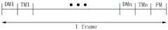
具体地,所述第二实施方式中,所述内嵌式触控液晶显示面板的一帧图像显示时间(1frame)包括多个(如n个)显示时段DM1~DMn、多个(如n个)触控时段TM1~TMn及一压感时段FM,所述显示时段DMi与所述触控时段TMi的数量可以相等,如均为n个,n可以为大于等于3的自然数,i为大于等于1小于等于n的自然数,且所述显示时段DMi与所述触控时段TMi周期性一一交替出现,所述压感时段Dm位于所述多个显示时段DM1~DMn与所述多个触控时段TM1~TMn之后。可以理解,在变更实施方式中,所述压感时段Dm也可以位于所述多个显示时段DM1~DMn与所述多个触控时段TM1~TMn之前。可以理解,在所述显示时段、所述触控时段、及所述压感时段,触控电极1231、压感电极1232及导电图案层113被施加的信号与第一实施方式中基本相同,此处就不再赘述。进一步地,与第一实施方式相比,所述显示时段DM与所述多个显示时段DM1~DMn时间相等,即DM=DM1+DM2+…+DMn;所述触控时段TM与多个触控时段TM1~TMn时间相等,即TM=TM1+TM2+…+TMn。Specifically, in the second embodiment, one frame of image display time (1 frame) of the in-cell touch liquid crystal display panel includes multiple (eg, n) display periods DM1 to DMn, multiple (eg, n) display periods DM1 to DMn. ) touch period TM1-TMn and a pressure-sensitive period FM, the number of the display period DMi and the touch period TMi can be equal, such as n, n can be a natural number greater than or equal to 3, i is greater than or equal to 1 is a natural number less than or equal to n, and the display period DMi and the touch period TMi appear alternately one by one periodically, and the pressure-sensitive period Dm is located in the plurality of display periods DM1-DMn and the plurality of touch periods After the period TM1 to TMn. It can be understood that, in a modified embodiment, the pressure-sensitive period Dm may also be located before the plurality of display periods DM1 ˜DMn and the plurality of touch periods TM1 ˜TMn. It can be understood that in the display period, the touch period, and the pressure-sensitive period, the signals applied to the
请参阅图6,图6是本发明第三实施方式的内嵌式触控液晶显示面板的驱动时序示意图。所述第三实施方式的内嵌式触控液晶显示面板与第一实施方式的内嵌式触控液晶显示面板的结构基本相同,也就是说,上述对所述第一实施方式的内嵌式触控液晶显示面板的描述基本上均可以适用于所述第三实施方式的内嵌式触控液晶显示面板,二者的主要差别在于:所述第三实施方式的内嵌式触控液晶显示面板的驱动时序与第一实施方式中有所不同。Please refer to FIG. 6 . FIG. 6 is a schematic diagram of the driving timing of the in-cell touch liquid crystal display panel according to the third embodiment of the present invention. The in-cell touch liquid crystal display panel of the third embodiment has basically the same structure as the in-cell touch liquid crystal display panel of the first embodiment. The description of the touch LCD panel can basically be applied to the in-cell touch LCD panel of the third embodiment, and the main difference between the two is that the in-cell touch LCD panel of the third embodiment The driving timing of the panel is different from that in the first embodiment.
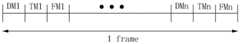
所述内嵌式触控液晶显示面板的一帧图像显示时间(1frame)包括多个(如n个)显示时段DM1~DMn、多个(如n个)触控时段TM1~TMn及多个(如n个)压感时段FM1~FMn,所述显示时段、所述触控时段、所述压感时段的数量可以相等,如均为n个,n可以为大于等于3的自然数,i为大于等于1小于等于n的自然数。任意连续的三个时段分别为一显示时段、一触控时段、一压感时段,所述显示时段、所述触控时段、所述压感时段依预定顺序周期性交替出现。具体地,所述显示时段、所述触控时段、所述压感时段可以按照所述顺序依次出现。A frame of image display time (1 frame) of the in-cell touch liquid crystal display panel includes multiple (eg, n) display periods DM1 to DMn, multiple (eg, n) touch periods TM1 to TMn, and multiple (eg, n) touch periods TM1 to TMn. For example, n) pressure-sensitive periods FM1 to FMn, the number of the display period, the touch period, and the pressure-sensitive period can be equal, such as n, n can be a natural number greater than or equal to 3, and i is greater than or equal to 3 A natural number equal to 1 and less than or equal to n. The three consecutive periods are a display period, a touch period, and a pressure-sensing period, respectively, and the display period, the touch-sensing period, and the pressure-sensing period periodically alternate in a predetermined order. Specifically, the display period, the touch period, and the pressure-sensing period may appear sequentially in the order described.
可以理解,在所述显示时段、所述触控时段、及所述压感时段,触控电极1231、压感电极1232及导电图案层113被施加的信号与第一实施方式中基本相同,此处就不再赘述。进一步地,与第一实施方式相比,所述显示时段DM与所述多个显示时段DM1~DMn时间相等,即DM=DM1+DM2+…+DMn;所述触控时段TM与多个触控时段TM1~TMn时间相等,即TM=TM1+TM2+…+TMn;所述压感时段FM=FM1+FM2+…+FMn。It can be understood that in the display period, the touch period, and the pressure-sensitive period, the signals applied to the
图7是本发明第四实施方式的内嵌式触控液晶显示面板400的感测电极层的布线结构示意图。所述第四实施方式的内嵌式触控液晶显示面板400与第一实施方式的内嵌式触控液晶显示面板100的结构基本相同,也就是说,上述对所述第一实施方式的内嵌式触控液晶显示面板100的描述基本上均可以适用于所述第四实施方式的内嵌式触控液晶显示面板400,二者的主要差别在于:所述第四实施方式的内嵌式触控液晶显示面板400的连接压感电极4232的第二信号线4236的数量不同,具体地,所述第四实施方式中,相邻的两组或两组以上的触控电极4230对应的两个或两个以上的压感电极4232电性连接且通过同一条第二信号线4326接收压感驱动信号,由此,所述内嵌式触控液晶显示面板400可以减小压力感测通道数量为第一实施方式中的感测通道数量的一半,即减轻相应的驱动及感测电路的压力及成本。FIG. 7 is a schematic diagram of the wiring structure of the sensing electrode layer of the in-cell touch liquid
Claims (10)
Translated fromChineseApplications Claiming Priority (2)
| Application Number | Priority Date | Filing Date | Title |
|---|---|---|---|
| US201662374067P | 2016-08-12 | 2016-08-12 | |
| US62/374067 | 2016-08-12 |
Publications (2)
| Publication Number | Publication Date |
|---|---|
| CN107728356A CN107728356A (en) | 2018-02-23 |
| CN107728356Btrue CN107728356B (en) | 2020-11-03 |
Family
ID=61158958
Family Applications (1)
| Application Number | Title | Priority Date | Filing Date |
|---|---|---|---|
| CN201710592635.9AActiveCN107728356B (en) | 2016-08-12 | 2017-07-19 | Embedded touch liquid crystal display panel and embedded touch liquid crystal display module |
Country Status (3)
| Country | Link |
|---|---|
| US (1) | US10488963B2 (en) |
| CN (1) | CN107728356B (en) |
| TW (1) | TWI639937B (en) |
Families Citing this family (6)
| Publication number | Priority date | Publication date | Assignee | Title |
|---|---|---|---|---|
| TWI614695B (en)* | 2017-07-03 | 2018-02-11 | 敦泰電子有限公司 | High screen ratio display device with fingerprint identification |
| CN107621908B (en)* | 2017-10-23 | 2020-09-15 | 厦门天马微电子有限公司 | Display panel, display device and pressure touch method thereof |
| CN109240538A (en)* | 2018-09-03 | 2019-01-18 | 上海中航光电子有限公司 | Display panel and display device |
| TWI736896B (en)* | 2019-05-22 | 2021-08-21 | 凌巨科技股份有限公司 | In-cell touch display panel |
| TWI703491B (en)* | 2019-07-29 | 2020-09-01 | 友達光電股份有限公司 | Touch display panel |
| KR102786535B1 (en)* | 2021-12-31 | 2025-03-27 | 엘지디스플레이 주식회사 | Touch Sensing Display Device and Method for the same |
Citations (6)
| Publication number | Priority date | Publication date | Assignee | Title |
|---|---|---|---|---|
| CN1520544A (en)* | 2001-08-22 | 2004-08-11 | ������������ʽ���� | Touch sensor, display device with touch sensor, and position data generation method |
| CN103309611A (en)* | 2013-05-10 | 2013-09-18 | 北京京东方光电科技有限公司 | Method, device and system for touch screen display control |
| CN104991689A (en)* | 2015-08-10 | 2015-10-21 | 京东方科技集团股份有限公司 | Driving method and device of touch display panel and touch display panel |
| CN105607356A (en)* | 2016-01-04 | 2016-05-25 | 京东方科技集团股份有限公司 | Display panel and pressure induction method therefor |
| CN105717682A (en)* | 2015-12-31 | 2016-06-29 | 厦门天马微电子有限公司 | Touch display device |
| CN105759483A (en)* | 2016-05-13 | 2016-07-13 | 京东方科技集团股份有限公司 | Liquid crystal display panel, liquid crystal displayer and driving method of liquid crystal displayer |
Family Cites Families (9)
| Publication number | Priority date | Publication date | Assignee | Title |
|---|---|---|---|---|
| CN104641331B (en)* | 2012-09-20 | 2017-03-08 | 株式会社村田制作所 | Touch panel |
| JP5722954B2 (en)* | 2013-06-23 | 2015-05-27 | 日本写真印刷株式会社 | Touch panel with pressure detection function |
| CN203759677U (en)* | 2014-04-09 | 2014-08-06 | 京东方科技集团股份有限公司 | Touch screen and display device |
| CN105117058B (en)* | 2015-08-24 | 2018-07-06 | 联想(北京)有限公司 | A kind of touch panel, touch-control display panel and electronic equipment |
| CN204926044U (en)* | 2015-09-17 | 2015-12-30 | 京东方科技集团股份有限公司 | Contact screen |
| CN106557246B (en)* | 2015-09-30 | 2023-07-21 | 宸鸿科技(厦门)有限公司 | Three-dimensional input module |
| CN204965385U (en)* | 2015-10-15 | 2016-01-13 | 京东方科技集团股份有限公司 | In cell touch panel and display device |
| CN105630251B (en)* | 2016-03-17 | 2018-07-24 | 厦门天马微电子有限公司 | A kind of array substrate, display panel and display device |
| CN105955522B (en)* | 2016-04-20 | 2018-12-07 | 厦门天马微电子有限公司 | Touch control display apparatus and its driving method |
- 2017
- 2017-07-19CNCN201710592635.9Apatent/CN107728356B/enactiveActive
- 2017-08-01TWTW106125942Apatent/TWI639937B/enactive
- 2017-08-11USUS15/674,542patent/US10488963B2/enactiveActive
Patent Citations (7)
| Publication number | Priority date | Publication date | Assignee | Title |
|---|---|---|---|---|
| CN1520544A (en)* | 2001-08-22 | 2004-08-11 | ������������ʽ���� | Touch sensor, display device with touch sensor, and position data generation method |
| CN103309611A (en)* | 2013-05-10 | 2013-09-18 | 北京京东方光电科技有限公司 | Method, device and system for touch screen display control |
| WO2014180142A1 (en)* | 2013-05-10 | 2014-11-13 | 北京京东方光电科技有限公司 | Method, device, and system for controlling touchscreen display |
| CN104991689A (en)* | 2015-08-10 | 2015-10-21 | 京东方科技集团股份有限公司 | Driving method and device of touch display panel and touch display panel |
| CN105717682A (en)* | 2015-12-31 | 2016-06-29 | 厦门天马微电子有限公司 | Touch display device |
| CN105607356A (en)* | 2016-01-04 | 2016-05-25 | 京东方科技集团股份有限公司 | Display panel and pressure induction method therefor |
| CN105759483A (en)* | 2016-05-13 | 2016-07-13 | 京东方科技集团股份有限公司 | Liquid crystal display panel, liquid crystal displayer and driving method of liquid crystal displayer |
Also Published As
| Publication number | Publication date |
|---|---|
| US10488963B2 (en) | 2019-11-26 |
| TWI639937B (en) | 2018-11-01 |
| CN107728356A (en) | 2018-02-23 |
| US20180046297A1 (en) | 2018-02-15 |
| TW201805788A (en) | 2018-02-16 |
Similar Documents
| Publication | Publication Date | Title |
|---|---|---|
| CN107728356B (en) | Embedded touch liquid crystal display panel and embedded touch liquid crystal display module | |
| TWI633370B (en) | In-cell touch display panel | |
| US9864457B2 (en) | Display device with touch sensor | |
| CN103926729B (en) | Array substrate, color film substrate, touch display device and driving method thereof | |
| KR102228561B1 (en) | Display device indlucing touch sensor | |
| CN102707831B (en) | Touch pad and the touch-screen with this touch pad | |
| US10296152B2 (en) | Touch display panel | |
| US9075488B2 (en) | Virtual geometries for integrated display and sensing devices | |
| US10474278B2 (en) | Touch-control display panel and electronic device | |
| CN205121513U (en) | In cell touch panel and display device | |
| US20170351354A1 (en) | Display panel, touch input apparatus, sensing apparatus for sensing touch position and touch pressure from display panel, and sensing method | |
| US20130147724A1 (en) | Display device with integrated touch screen | |
| WO2017071543A1 (en) | Embedded touch screen, driving method thereof and display device | |
| US20130328829A1 (en) | In-cell touch display panel system with increased accuracy of touch positions | |
| US10185423B2 (en) | Plug-in touch display device and an electronic device | |
| US20180088700A1 (en) | Plug-in touch display with pressure sensing function | |
| TW201405180A (en) | Color filter substrate, touch-control liquid crystal display panel and device | |
| CN104407466A (en) | Display substrate, display panel and display device | |
| CN107728354A (en) | Embedded touch display device | |
| US10649263B2 (en) | Touch panel liquid crystal display device and method of driving the same | |
| US8217871B2 (en) | Touch-controlled liquid crystal display and touch panel thereof | |
| WO2013125191A1 (en) | Input device | |
| JP2015099407A (en) | Input device | |
| CN102004343A (en) | Liquid crystal display device integrated with touch screen | |
| CN107329302A (en) | Touch-control display module and electronic equipment |
Legal Events
| Date | Code | Title | Description |
|---|---|---|---|
| PB01 | Publication | ||
| PB01 | Publication | ||
| SE01 | Entry into force of request for substantive examination | ||
| SE01 | Entry into force of request for substantive examination | ||
| GR01 | Patent grant | ||
| GR01 | Patent grant |