CN107708595B - Ultra-dexterous surgical system user interface device - Google Patents
Ultra-dexterous surgical system user interface deviceDownload PDFInfo
- Publication number
- CN107708595B CN107708595BCN201580080006.7ACN201580080006ACN107708595BCN 107708595 BCN107708595 BCN 107708595BCN 201580080006 ACN201580080006 ACN 201580080006ACN 107708595 BCN107708595 BCN 107708595B
- Authority
- CN
- China
- Prior art keywords
- user interface
- interface device
- user
- ungrounded
- end effector
- Prior art date
- Legal status (The legal status is an assumption and is not a legal conclusion. Google has not performed a legal analysis and makes no representation as to the accuracy of the status listed.)
- Expired - Fee Related
Links
- 238000000034methodMethods0.000claimsabstractdescription95
- 230000008859changeEffects0.000claimsabstractdescription23
- 238000013519translationMethods0.000claimsabstractdescription21
- 238000003825pressingMethods0.000claimsabstractdescription20
- 239000012636effectorSubstances0.000claimsdescription137
- 230000033001locomotionEffects0.000claimsdescription118
- 239000012530fluidSubstances0.000claimsdescription11
- 230000004044responseEffects0.000claimsdescription8
- 230000000694effectsEffects0.000claimsdescription6
- 230000000994depressogenic effectEffects0.000claimsdescription4
- 230000010349pulsationEffects0.000claimsdescription3
- 230000003287optical effectEffects0.000description27
- 230000008901benefitEffects0.000description15
- 230000001133accelerationEffects0.000description9
- 230000006870functionEffects0.000description9
- 238000005259measurementMethods0.000description8
- 238000001356surgical procedureMethods0.000description8
- 239000000463materialSubstances0.000description7
- 238000002432robotic surgeryMethods0.000description6
- 208000027418Wounds and injuryDiseases0.000description4
- 230000006378damageEffects0.000description4
- 208000014674injuryDiseases0.000description4
- 230000008569processEffects0.000description4
- 210000001519tissueAnatomy0.000description4
- 210000000707wristAnatomy0.000description4
- 210000003484anatomyAnatomy0.000description3
- 230000008878couplingEffects0.000description3
- 238000010168coupling processMethods0.000description3
- 238000005859coupling reactionMethods0.000description3
- 230000007812deficiencyEffects0.000description3
- 210000004247handAnatomy0.000description3
- 230000036512infertilityEffects0.000description3
- 230000007246mechanismEffects0.000description3
- 239000004033plasticSubstances0.000description3
- 230000004224protectionEffects0.000description3
- 238000005096rolling processMethods0.000description3
- 239000013598vectorSubstances0.000description3
- 238000013459approachMethods0.000description2
- 238000004891communicationMethods0.000description2
- 230000007423decreaseEffects0.000description2
- 230000000881depressing effectEffects0.000description2
- 238000013461designMethods0.000description2
- 239000007788liquidSubstances0.000description2
- 238000012986modificationMethods0.000description2
- 230000004048modificationEffects0.000description2
- 238000000926separation methodMethods0.000description2
- 230000000007visual effectEffects0.000description2
- 210000001015abdomenAnatomy0.000description1
- 230000009471actionEffects0.000description1
- 238000004458analytical methodMethods0.000description1
- 238000003491arrayMethods0.000description1
- 238000003556assayMethods0.000description1
- 210000000988bone and boneAnatomy0.000description1
- 238000002591computed tomographyMethods0.000description1
- 230000008602contractionEffects0.000description1
- 230000003247decreasing effectEffects0.000description1
- 230000007547defectEffects0.000description1
- 229920001971elastomerPolymers0.000description1
- 210000000245forearmAnatomy0.000description1
- 230000008571general functionEffects0.000description1
- 238000002847impedance measurementMethods0.000description1
- 238000009434installationMethods0.000description1
- 230000003993interactionEffects0.000description1
- 230000002452interceptive effectEffects0.000description1
- 238000002595magnetic resonance imagingMethods0.000description1
- 210000000056organAnatomy0.000description1
- 238000002360preparation methodMethods0.000description1
- 230000035807sensationEffects0.000description1
- 229920002379silicone rubberPolymers0.000description1
- 239000004945silicone rubberSubstances0.000description1
- 239000007779soft materialSubstances0.000description1
- 230000000153supplemental effectEffects0.000description1
- 239000002344surface layerSubstances0.000description1
- 238000010408sweepingMethods0.000description1
- 238000012549trainingMethods0.000description1
Images


Classifications
- A—HUMAN NECESSITIES
- A61—MEDICAL OR VETERINARY SCIENCE; HYGIENE
- A61B—DIAGNOSIS; SURGERY; IDENTIFICATION
- A61B34/00—Computer-aided surgery; Manipulators or robots specially adapted for use in surgery
- A61B34/70—Manipulators specially adapted for use in surgery
- A61B34/74—Manipulators with manual electric input means
- A—HUMAN NECESSITIES
- A61—MEDICAL OR VETERINARY SCIENCE; HYGIENE
- A61B—DIAGNOSIS; SURGERY; IDENTIFICATION
- A61B34/00—Computer-aided surgery; Manipulators or robots specially adapted for use in surgery
- A61B34/30—Surgical robots
- A61B34/35—Surgical robots for telesurgery
- A—HUMAN NECESSITIES
- A61—MEDICAL OR VETERINARY SCIENCE; HYGIENE
- A61B—DIAGNOSIS; SURGERY; IDENTIFICATION
- A61B34/00—Computer-aided surgery; Manipulators or robots specially adapted for use in surgery
- A61B34/30—Surgical robots
- A61B34/37—Leader-follower robots
- A—HUMAN NECESSITIES
- A61—MEDICAL OR VETERINARY SCIENCE; HYGIENE
- A61B—DIAGNOSIS; SURGERY; IDENTIFICATION
- A61B34/00—Computer-aided surgery; Manipulators or robots specially adapted for use in surgery
- A61B34/70—Manipulators specially adapted for use in surgery
- A61B34/76—Manipulators having means for providing feel, e.g. force or tactile feedback
- B—PERFORMING OPERATIONS; TRANSPORTING
- B25—HAND TOOLS; PORTABLE POWER-DRIVEN TOOLS; MANIPULATORS
- B25J—MANIPULATORS; CHAMBERS PROVIDED WITH MANIPULATION DEVICES
- B25J13/00—Controls for manipulators
- B25J13/02—Hand grip control means
- B25J13/025—Hand grip control means comprising haptic means
- B—PERFORMING OPERATIONS; TRANSPORTING
- B25—HAND TOOLS; PORTABLE POWER-DRIVEN TOOLS; MANIPULATORS
- B25J—MANIPULATORS; CHAMBERS PROVIDED WITH MANIPULATION DEVICES
- B25J13/00—Controls for manipulators
- B25J13/08—Controls for manipulators by means of sensing devices, e.g. viewing or touching devices
- B25J13/086—Proximity sensors
- B—PERFORMING OPERATIONS; TRANSPORTING
- B25—HAND TOOLS; PORTABLE POWER-DRIVEN TOOLS; MANIPULATORS
- B25J—MANIPULATORS; CHAMBERS PROVIDED WITH MANIPULATION DEVICES
- B25J3/00—Manipulators of leader-follower type, i.e. both controlling unit and controlled unit perform corresponding spatial movements
- A—HUMAN NECESSITIES
- A61—MEDICAL OR VETERINARY SCIENCE; HYGIENE
- A61B—DIAGNOSIS; SURGERY; IDENTIFICATION
- A61B17/00—Surgical instruments, devices or methods
- A61B2017/00017—Electrical control of surgical instruments
- A61B2017/00207—Electrical control of surgical instruments with hand gesture control or hand gesture recognition
- A—HUMAN NECESSITIES
- A61—MEDICAL OR VETERINARY SCIENCE; HYGIENE
- A61B—DIAGNOSIS; SURGERY; IDENTIFICATION
- A61B17/00—Surgical instruments, devices or methods
- A61B2017/00017—Electrical control of surgical instruments
- A61B2017/00212—Electrical control of surgical instruments using remote controls
- A—HUMAN NECESSITIES
- A61—MEDICAL OR VETERINARY SCIENCE; HYGIENE
- A61B—DIAGNOSIS; SURGERY; IDENTIFICATION
- A61B34/00—Computer-aided surgery; Manipulators or robots specially adapted for use in surgery
- A61B34/20—Surgical navigation systems; Devices for tracking or guiding surgical instruments, e.g. for frameless stereotaxis
- A61B2034/2046—Tracking techniques
- A61B2034/2048—Tracking techniques using an accelerometer or inertia sensor
- A—HUMAN NECESSITIES
- A61—MEDICAL OR VETERINARY SCIENCE; HYGIENE
- A61B—DIAGNOSIS; SURGERY; IDENTIFICATION
- A61B34/00—Computer-aided surgery; Manipulators or robots specially adapted for use in surgery
- A61B34/20—Surgical navigation systems; Devices for tracking or guiding surgical instruments, e.g. for frameless stereotaxis
- A61B2034/2046—Tracking techniques
- A61B2034/2055—Optical tracking systems
- A—HUMAN NECESSITIES
- A61—MEDICAL OR VETERINARY SCIENCE; HYGIENE
- A61B—DIAGNOSIS; SURGERY; IDENTIFICATION
- A61B90/00—Instruments, implements or accessories specially adapted for surgery or diagnosis and not covered by any of the groups A61B1/00 - A61B50/00, e.g. for luxation treatment or for protecting wound edges
- A61B90/06—Measuring instruments not otherwise provided for
- A61B2090/064—Measuring instruments not otherwise provided for for measuring force, pressure or mechanical tension
- A61B2090/065—Measuring instruments not otherwise provided for for measuring force, pressure or mechanical tension for measuring contact or contact pressure
- A—HUMAN NECESSITIES
- A61—MEDICAL OR VETERINARY SCIENCE; HYGIENE
- A61B—DIAGNOSIS; SURGERY; IDENTIFICATION
- A61B90/00—Instruments, implements or accessories specially adapted for surgery or diagnosis and not covered by any of the groups A61B1/00 - A61B50/00, e.g. for luxation treatment or for protecting wound edges
- A61B90/06—Measuring instruments not otherwise provided for
- A61B2090/067—Measuring instruments not otherwise provided for for measuring angles
- A—HUMAN NECESSITIES
- A61—MEDICAL OR VETERINARY SCIENCE; HYGIENE
- A61B—DIAGNOSIS; SURGERY; IDENTIFICATION
- A61B90/00—Instruments, implements or accessories specially adapted for surgery or diagnosis and not covered by any of the groups A61B1/00 - A61B50/00, e.g. for luxation treatment or for protecting wound edges
- A61B90/08—Accessories or related features not otherwise provided for
- A61B2090/0818—Redundant systems, e.g. using two independent measuring systems and comparing the signals
- A—HUMAN NECESSITIES
- A61—MEDICAL OR VETERINARY SCIENCE; HYGIENE
- A61B—DIAGNOSIS; SURGERY; IDENTIFICATION
- A61B2562/00—Details of sensors; Constructional details of sensor housings or probes; Accessories for sensors
- A61B2562/16—Details of sensor housings or probes; Details of structural supports for sensors
- A61B2562/168—Fluid filled sensor housings
- Y—GENERAL TAGGING OF NEW TECHNOLOGICAL DEVELOPMENTS; GENERAL TAGGING OF CROSS-SECTIONAL TECHNOLOGIES SPANNING OVER SEVERAL SECTIONS OF THE IPC; TECHNICAL SUBJECTS COVERED BY FORMER USPC CROSS-REFERENCE ART COLLECTIONS [XRACs] AND DIGESTS
- Y10—TECHNICAL SUBJECTS COVERED BY FORMER USPC
- Y10S—TECHNICAL SUBJECTS COVERED BY FORMER USPC CROSS-REFERENCE ART COLLECTIONS [XRACs] AND DIGESTS
- Y10S901/00—Robots
- Y10S901/02—Arm motion controller
- Y—GENERAL TAGGING OF NEW TECHNOLOGICAL DEVELOPMENTS; GENERAL TAGGING OF CROSS-SECTIONAL TECHNOLOGIES SPANNING OVER SEVERAL SECTIONS OF THE IPC; TECHNICAL SUBJECTS COVERED BY FORMER USPC CROSS-REFERENCE ART COLLECTIONS [XRACs] AND DIGESTS
- Y10—TECHNICAL SUBJECTS COVERED BY FORMER USPC
- Y10S—TECHNICAL SUBJECTS COVERED BY FORMER USPC CROSS-REFERENCE ART COLLECTIONS [XRACs] AND DIGESTS
- Y10S901/00—Robots
- Y10S901/46—Sensing device
Landscapes
- Engineering & Computer Science (AREA)
- Health & Medical Sciences (AREA)
- Life Sciences & Earth Sciences (AREA)
- Surgery (AREA)
- Robotics (AREA)
- Medical Informatics (AREA)
- Biomedical Technology (AREA)
- Heart & Thoracic Surgery (AREA)
- Nuclear Medicine, Radiotherapy & Molecular Imaging (AREA)
- Molecular Biology (AREA)
- Animal Behavior & Ethology (AREA)
- General Health & Medical Sciences (AREA)
- Public Health (AREA)
- Veterinary Medicine (AREA)
- Mechanical Engineering (AREA)
- Human Computer Interaction (AREA)
- Manipulator (AREA)
- User Interface Of Digital Computer (AREA)
Abstract
Translated fromChinese
Description
Translated fromChinese通过引用而结合任何优先权申请Incorporate by reference any priority application
本申请案在美国法典第35篇第119条(e)款下主张2015年4月23日提交的美国临时申请号62/151596的优先权权益,所述美国临时申请以全文引用的方式并入本文中且应被视为本说明书的一部分。本申请以全文引用的方式并入有2014年3月13日提交的国际申请号PCT/US2014/026115,其在美国指定且于2014年9月25日用英文公布为WO 2014/151621,所述国际申请应被视为本说明书的一部分。本申请以全文引用的方式并入有2015年2月24日提交的美国临时号62/120,128,所述美国临时号以全文引用的方式并入本文中,其应被视为本说明书的一部分。This application claims the benefit of priority under 35 USC § 119(e) to US Provisional Application No. 62/151596, filed April 23, 2015, which is incorporated by reference in its entirety is herein and should be considered part of this specification. This application is hereby incorporated by reference in its entirety into International Application No. PCT/US2014/026115, filed March 13, 2014, designated in the United States and published in English as WO 2014/151621 on September 25, 2014, which states The international application should be considered as part of this specification. This application is incorporated by reference in its entirety into US Provisional No. 62/120,128, filed February 24, 2015, which is incorporated herein by reference in its entirety and should be considered a part of this specification.
技术领域technical field
手术机器人允许外科医生以微创方式对患者实施手术。本申请涉及手术系统和方法,且更具体地说涉及用于具有一个或多个超灵巧型手术臂和一个或多个末端执行器的超灵巧型手术系统的用户接口装置及其操作方法。Surgical robots allow surgeons to operate on patients in a minimally invasive manner. The present application relates to surgical systems and methods, and more particularly to user interface devices and methods of operation thereof for hyperdexterous surgical systems having one or more hyperdexterous surgical arms and one or more end effectors.
背景技术Background technique
机器人的使用在所有生活方面发展和扩散。一些机器人是自主的,在于除了刚刚启动机器人并指示机器人执行一组任务外无需人为干预。一些其它机器人由人类操作员控制。用于手术的市售机器人系统是后一种的实例,其中操作员控制机器人。The use of robots develops and proliferates in all aspects of life. Some robots are autonomous in that they require no human intervention other than just starting the robot and instructing the robot to perform a set of tasks. Some other robots are controlled by human operators. Commercially available robotic systems for surgery are an example of the latter, where an operator controls the robot.
通常,此类系统具有操作员能够借以操纵机器人的控制台。因此,外科医生在使用市售机器人手术系统时远离患者,常常坐在远程控制台处。通常,市售系统使用机械接地用户接口装置。通常,这些接地用户接口装置在空间上固定到用户控制台。接地用户接口装置传达取向感和方向感。接地用户接口装置在自由空间中不进行操纵。Typically, such systems have a console through which an operator can manipulate the robot. As a result, surgeons often sit at a remote console while using commercially available robotic surgical systems away from the patient. Typically, commercially available systems use a mechanically grounded user interface device. Typically, these grounded user interface devices are spatially secured to the user console. The grounded user interface device conveys a sense of orientation and direction. Grounded user interface devices are not manipulated in free space.
在市售系统中,接地用户接口装置可在各种情形下(例如当机器人系统达到接头极限时)提供反馈。反馈可由用户输入装置难以移动的用户简单感觉提供。在更高级的方法中,机器人系统可有意使接地用户接口装置运动以提供反馈。In commercially available systems, a grounded user interface device can provide feedback in various situations, such as when the robotic system reaches a joint limit. Feedback may be provided by the user's simple sense of difficulty in moving the user input device. In a more advanced approach, the robotic system may intentionally move the grounded user interface device to provide feedback.
接地用户接口装置的主要功能是提供操作员灵巧地操纵工具和末端执行器的能力。在市售机器人手术系统中,大型机器人臂控制机器人工具。工具被插入到小切口中。机器人工具的远端通常包含用于在患者体内进行过程的末端执行器(例如,抓紧器、钉合器等)。在机器人臂的能力限制内,末端执行器在空间中平移。外科医生通常根据远离患者的沉浸式控制台控制机器人臂。机器人工具也能够进行某些手术任务,但不是非常适于其它手术任务。The primary function of the grounded user interface device is to provide the operator with the ability to maneuver the tool and end effector dexterously. In commercially available robotic surgery systems, large robotic arms control robotic tools. Tools are inserted into small incisions. The distal end of the robotic tool typically contains an end effector (eg, a grasper, stapler, etc.) for performing the procedure within the patient. The end effector translates in space within the capabilities of the robotic arm. The surgeon typically controls the robotic arm from an immersive console remote from the patient. Robotic tools are also capable of certain surgical tasks, but are not well suited for others.
在市售手术机器人系统中,大体上经由机器人相机观察机器人工具的运动。机器人相机的运动由机器人臂控制,同样也像其它机器人工具一样在外科医生的控制下。控制接地用户接口装置的外科医生的手的移动可映射到机器人工具在相机的参考系中的移动。接地用户接口装置的运动映射到机器人相机的参考系内的机器人工具的远端执行器。提供给外科医生的参考信息因此受限于相机所提供的视野。显示器通常严格地从由机器人握持的相机的视角示出机器人工具的远端的运动。In commercially available surgical robotic systems, the motion of the robotic tool is generally observed via a robotic camera. The movement of the robotic camera is controlled by the robotic arm, which is also under the control of the surgeon like other robotic tools. Movements of the surgeon's hand controlling the grounded user interface device can be mapped to movements of the robotic tool in the camera's frame of reference. The motion of the grounded user interface device is mapped to the robotic tool's remote effector within the reference frame of the robotic camera. The reference information provided to the surgeon is thus limited by the field of view provided by the camera. The display typically shows the motion of the distal end of the robotic tool strictly from the perspective of a camera held by the robot.
外科医生因此必须借助相机所提供的有限的信息创建身体结构的构思模型,从而根据特定任务的需要控制机器人工具。由于外科医生在控制台处的远程位置,因此他无法获取患者的额外视野以便加强他对手术空间的理解。机器人相机的有限视角使得手术的各方面不太自然。举例来说,从腹部的一个四分之一圆周到另一四分之一圆周进行大的移动、尤其是包括相机掠过包含患者的中线的圆弧的运动极具挑战性。The surgeon must therefore create a conceptual model of the body structure with the limited information provided by the camera to control the robotic tool as needed for a specific task. Due to the surgeon's remote location at the console, he is unable to obtain additional views of the patient in order to enhance his understanding of the surgical space. The limited field of view of the robotic camera makes all aspects of surgery unnatural. For example, making large movements from one quarter of the abdomen to another, especially movements involving the camera sweeping across an arc containing the patient's midline, is extremely challenging.
通常,外科医生通过提供沉浸式体验的观察器来观察手术部位和工具。在一些情况下,外科医生与辅助工作人员之间的通信由于外科医生在控制台上的位置而受限或受阻。进行机器人手术的团队需要高度训练和熟练,这是因为外科医生远离患者且无法直接与工作人员通信。耗费数月(在一些情况下数年)的实践以在进行机器人手术的情形中实现高水平的效率。这使得团队成员难以被替换。另外,从此远程位置(控制台处),外科医生无法在控制机器人臂的同时同步使用手动工具。Often, surgeons view surgical sites and tools through viewers that provide an immersive experience. In some cases, communication between the surgeon and ancillary staff is limited or obstructed by the surgeon's position on the console. Teams performing robotic surgery require a high degree of training and proficiency because the surgeon is remote from the patient and cannot communicate directly with the staff. It takes months (in some cases years) of practice to achieve a high level of efficiency in situations where robotic surgery is performed. This makes it difficult for team members to be replaced. Additionally, from this remote location (at the console), the surgeon cannot synchronize the use of hand tools while controlling the robotic arm.
当前系统的缺点在于其向外科医生提供的信息有限。通常,此信息局限于机器人相机的视野。外科医生无法在使用接地用户接口装置的同时观察患者。外科医生无法接收关于患者的身体结构的反馈。外科医生无法在使用接地用户接口装置的同时使用手动工具或触碰患者。市售机器人手术系统的另一缺点在于其不允许外科医生能够在手术期间重新定位他或她的位置。外科医生必须留在沉浸式控制台处以操纵接地用户接口装置借助机器人工具的末端执行器进行手术任务。The disadvantage of the current system is that it provides the surgeon with limited information. Typically, this information is limited to the field of view of the robot camera. The surgeon cannot observe the patient while using the grounded user interface device. The surgeon cannot receive feedback about the patient's anatomy. The surgeon cannot use hand tools or touch the patient while using the grounded user interface device. Another disadvantage of commercially available robotic surgical systems is that they do not allow the surgeon to reposition his or her position during surgery. The surgeon must remain at the immersive console to manipulate the grounded user interface device to perform surgical tasks with the robotic tool's end effector.
发明内容SUMMARY OF THE INVENTION
需要这样一种用户接口装置:其克服上文所论述的市售机器人手术系统的缺陷且当外科医生进行手术过程时提供灵活性。There is a need for a user interface device that overcomes the deficiencies of the commercially available robotic surgical systems discussed above and that provides flexibility as the surgeon performs a surgical procedure.
用户接口装置与上述市售用户接口装置相比提供优点。不接地和主体接地用户接口装置的一个方面在于这些装置在自由空间中进行操纵。不接地和主体接地用户接口装置有利地不限于控制台。不接地和主体接地用户接口装置可以用户站立或坐下时的自然高度进行操纵,且可有利地在外科医生围绕手术室移动时进行操纵。The user interface device provides advantages over the above-described commercially available user interface devices. One aspect of ungrounded and body grounded user interface devices is that these devices operate in free space. Ungrounded and body grounded user interface devices are advantageously not limited to consoles. The ungrounded and body grounded user interface device can be maneuvered at the user's natural height when standing or sitting, and can be advantageously maneuvered as the surgeon moves around the operating room.
不接地和主体接地用户接口装置的一个方面在于这些装置可以是有线的或无线的。无线不接地和主体接地用户接口装置可有利地允许用户围绕操作场所自由移动而没有电线的限制。有线不接地和主体接地用户接口装置可提供更可靠的连接以传达来自不接地和主体接地用户接口装置的信号和信息。One aspect of ungrounded and body grounded user interface devices is that these devices can be wired or wireless. Wireless ungrounded and body grounded user interface devices can advantageously allow a user to move freely around the operating site without the constraints of wires. Wired ungrounded and bulk grounded user interface devices may provide a more reliable connection for communicating signals and information from ungrounded and bulk grounded user interface devices.
不接地和主体接地用户接口装置的一个方面在于这些装置可具有提供取向感的形状。不接地和主体接地用户接口装置可包含接口或表面,用户可将他或她的手指放在所述接口或表面上。不接地和主体接地用户接口装置可具有细长形状。举例来说,细长形状的末端可提供取向感(例如,正面、反面)。举例来说,不接地和主体接地用户接口装置的表面可提供取向感(例如,顶部、底部)。One aspect of ungrounded and body grounded user interface devices is that these devices can have shapes that provide a sense of orientation. Ungrounded and body grounded user interface devices may contain an interface or surface on which a user may place his or her fingers. The ungrounded and body grounded user interface device may have an elongated shape. For example, the elongated shaped ends can provide a sense of orientation (eg, front, back). For example, ungrounded and body grounded surfaces of the user interface device may provide a sense of orientation (eg, top, bottom).
不接地和主体接地用户接口装置的一个方面在于这些装置提供可在何处操作不接地和主体接地用户接口装置的通用性。不接地和主体接地用户接口装置有利地是便携式的且可随外科医生一起移动。不接地和主体接地用户接口装置可根据相对于操作场所内的患者的任何位置和/或取向使用。不接地和主体接地用户接口装置可邻近患者操作。不接地和主体接地用户接口装置可在远离患者的位置处(例如,控制台处)操作。不接地和主体接地用户接口装置可在用户相对于患者使他或她自我重新取向时操作。One aspect of ungrounded and body grounded user interface devices is that these devices provide versatility where the ungrounded and body grounded user interface devices can be operated. The ungrounded and body grounded user interface device is advantageously portable and movable with the surgeon. Ungrounded and body grounded user interface devices may be used in any position and/or orientation relative to the patient within the operating site. Ungrounded and body grounded user interface devices can be operated adjacent to the patient. Ungrounded and body grounded user interface devices can be operated at a location remote from the patient (eg, at a console). The ungrounded and body grounded user interface devices are operable when the user reorients himself or herself relative to the patient.
不接地和主体接地用户接口装置的一个方面在于这些装置可向用户提供反馈。不接地和主体接地用户接口装置可提供有关例如超灵巧型手术系统的移动限制的反馈。不接地和主体接地用户接口装置可提供接头极限的反馈。不接地和主体接地用户接口装置可提供关于手术空间的反馈。不接地和主体接地用户接口装置可当末端执行器与硬的物体碰撞或有可能与硬的物体碰撞时提供反馈。不接地和主体接地用户接口装置可提供有关末端执行器触碰的物体的硬度或柔软度的反馈。不接地和主体接地用户接口装置可提供压力形式的反馈。不接地和主体接地用户接口装置可提供声音形式的反馈。不接地和主体接地用户接口装置可提供例如光形式等视觉反馈。One aspect of ungrounded and body grounded user interface devices is that these devices can provide feedback to the user. Ungrounded and body grounded user interface devices can provide feedback regarding, for example, movement limitations of a hyperdexterous surgical system. Ungrounded and body grounded user interface devices provide feedback on joint limits. Ungrounded and body grounded user interface devices can provide feedback about the surgical space. The ungrounded and body grounded user interface device can provide feedback when the end effector collides with a hard object or is likely to collide with a hard object. Ungrounded and body grounded user interface devices can provide feedback on the stiffness or softness of the object touched by the end effector. Ungrounded and body grounded user interface devices may provide feedback in the form of pressure. Ungrounded and body grounded user interface devices may provide feedback in the form of sounds. Ungrounded and body grounded user interface devices may provide visual feedback, such as in the form of light.
不接地和主体接地用户接口装置的一个方面在于这些装置可防止患者受伤。不接地和主体接地用户接口装置可有利地防止末端执行器跟着不接地和主体接地用户接口装置,例如当使不接地和主体接地用户接口装置无意落下时。不接地和主体接地用户接口装置可提供阻抗信息。阻抗值将会在用户使不接地和主体接地用户接口装置落下时改变。超灵巧型手术系统可防止当阻抗值超过阈值时末端执行器跟着不接地和主体接地用户接口装置的运动。不接地和主体接地用户接口装置可提供加速度信息。加速度将在用户使不接地和主体接地用户接口装置落下时改变。超灵巧型手术系统可防止当加速度值超过阈值时末端执行器跟着不接地和主体接地用户接口装置的运动。One aspect of ungrounded and body grounded user interface devices is that these devices prevent patient injury. The ungrounded and body grounded user interface device may advantageously prevent the end effector from following the ungrounded and body grounded user interface device, such as when the ungrounded and body grounded user interface device is inadvertently dropped. Ungrounded and body grounded user interface devices can provide impedance information. The impedance value will change when the user drops the ungrounded and body grounded user interface device. The hyperdexterous surgical system prevents the end effector from following movement of the ungrounded and body grounded user interface device when the impedance value exceeds a threshold value. Ungrounded and body grounded user interface devices can provide acceleration information. The acceleration will change when the user drops the ungrounded and body grounded user interface device. The hyperdexterous surgical system prevents the end effector from following movement of the ungrounded and body grounded user interface device when the acceleration value exceeds a threshold.
在一些实施例中,公开手持型便携式用户接口装置。装置可包含被配置成握持在用户手中的主体。在一些实施例中,主体包括近端部分和远端部分,并沿着由主体的近端与远端之间的纵向轴线限定的长度延伸。在一些实施例中,主体沿着沿横向于纵向轴线延伸的横向轴线限定的宽度延伸。在一些实施例中,主体的长度大于宽度。在一些实施例中,主体包括外表面,所述外表面被配置成由用户的手的手指夹持且促进用户的手对主体的平移和旋转。装置可包含设置在主体内的一个或多个传感器。在一些实施例中,一个或多个传感器被配置成将主体的位置和取向信息中的一个或两个提供到控制系统。在一些实施例中,主体被配置成经由主体的平移、主体的旋转、用户的手指对外表面的按压以及主体的纵向轴线的角取向的变化中的一个或多个接收来自用户的控制输入。In some embodiments, a handheld portable user interface device is disclosed. The device may include a body configured to be held in a user's hand. In some embodiments, the body includes a proximal portion and a distal portion and extends along a length defined by a longitudinal axis between the proximal and distal ends of the body. In some embodiments, the body extends along a width defined along a transverse axis extending transverse to the longitudinal axis. In some embodiments, the length of the body is greater than the width. In some embodiments, the body includes an outer surface configured to be gripped by the fingers of the user's hand and to facilitate translation and rotation of the body by the user's hand. The device may include one or more sensors disposed within the body. In some embodiments, the one or more sensors are configured to provide one or both of the subject's position and orientation information to the control system. In some embodiments, the body is configured to receive control input from the user via one or more of translation of the body, rotation of the body, pressing of the user's finger on the outer surface, and changes in the angular orientation of the longitudinal axis of the body.
在一些实施例中,主体被配置成经由主体的由用户的手的手指夹持的外表面向用户提供触觉反馈。在一些实施例中,用户接口装置仅仅由用户的手支撑。在一些实施例中,用户接口装置被配置成将输入提供到控制系统以将用户接口装置的运动转变成机器人臂的末端执行器的运动。在一些实施例中,一个或多个传感器提供功能冗余。在一些实施例中,一个或多个传感器是不同类型的。在一些实施例中,一个或多个传感器包含接近度传感器。在一些实施例中,外表面被配置成由用户下压。在一些实施例中,主体包括被配置成以流体填充的腔室,其中用户对外表面的下压使腔室中所感测的压力改变,所感测的压力的所述变化被传达到控制系统以将所感测的压力转换成借助主体控制的机器人臂的末端执行器所施加的力。在一些实施例中,主体进一步包括泵,所述泵被配置成改变腔室的压力,从而向用户提供触觉反馈。In some embodiments, the body is configured to provide tactile feedback to the user via an outer surface of the body that is gripped by the fingers of the user's hand. In some embodiments, the user interface device is supported only by the user's hand. In some embodiments, the user interface device is configured to provide input to the control system to translate motion of the user interface device into motion of the end effector of the robotic arm. In some embodiments, one or more sensors provide functional redundancy. In some embodiments, the one or more sensors are of different types. In some embodiments, the one or more sensors comprise proximity sensors. In some embodiments, the outer surface is configured to be depressed by a user. In some embodiments, the body includes a chamber configured to be filled with fluid, wherein depression of the outer surface by the user causes a change in the pressure sensed in the chamber, the change in the sensed pressure being communicated to the control system to The sensed pressure is converted into a force exerted by the end effector of the robotic arm controlled by the body. In some embodiments, the body further includes a pump configured to vary the pressure of the chamber to provide haptic feedback to the user.
在一些实施例中,公开手持型用户接口装置。装置可包含主体,所述主体被配置成握持在用户的手中且仅仅由用户的手支撑。任选地,主体还可由用户的臂支撑。在一些实施例中,主体包括外表面,所述外表面被配置成由用户的手的手指夹持以促进用户的手对主体的平移和旋转。装置可包含设置在主体内的一个或多个传感器。在一些实施例中,一个或多个传感器被配置成将主体的位置和取向信息中的一个或两个提供到控制系统。在一些实施例中,主体被配置成经由主体的由用户的手指夹持的外表面向用户提供反馈。In some embodiments, a handheld user interface device is disclosed. The device may include a body configured to be held in a user's hand and supported only by the user's hand. Optionally, the body may also be supported by the user's arms. In some embodiments, the body includes an outer surface configured to be gripped by the fingers of the user's hand to facilitate translation and rotation of the body by the user's hand. The device may include one or more sensors disposed within the body. In some embodiments, the one or more sensors are configured to provide one or both of the subject's position and orientation information to the control system. In some embodiments, the body is configured to provide feedback to the user via an outer surface of the body that is gripped by the user's fingers.
在一些实施例中,主体被配置成经由主体的平移、主体的旋转、用户的手指对外表面的按压、以及主体的纵向轴线的角取向的变化中的一个或多个接收来自用户的控制输入。装置可任选地包含内部底盘,所述内部底盘被配置成在主体的外表层内移动以调整用户接口装置的纵向轴线的取向。在一些实施例中,内部底盘相对于外表层移动以达到所希望的俯仰和/或偏转取向并以触觉方式将此传达给用户。在一些实施例中,内部底盘用选自由以下组成的群组中的以下方式中的一种移动:扩张、缩回、脉动和旋转。在一些实施例中,内部底盘具有实现内部底盘的运动的一个或多个致动器。在一些实施例中,一个或多个致动器包括可驱动来达到所希望的滚动取向的环圈。在一些实施例中,内部底盘调整俯仰、偏转和/或滚动取向以维持用户接口装置轴线的纵向轴线与由用户接口装置控制的装置(例如,末端执行器)的轴线对齐。在一些实施例中,内部底盘响应于由用户接口装置控制的装置(例如,末端执行器)上的力调整俯仰、偏转和/或滚动取向。在一些实施例中,主体包括用于改变主体的形状的一个或多个致动器。在一些实施例中,主体包括用于改变主体的形状的一个或多个压力腔室。In some embodiments, the body is configured to receive control input from the user via one or more of translation of the body, rotation of the body, pressing of the user's finger on the outer surface, and changes in the angular orientation of the longitudinal axis of the body. The device may optionally include an internal chassis configured to move within the outer skin of the body to adjust the orientation of the longitudinal axis of the user interface device. In some embodiments, the inner chassis moves relative to the outer skin to achieve the desired pitch and/or yaw orientation and tactilely communicate this to the user. In some embodiments, the inner chassis moves in one of the following manners selected from the group consisting of: expanding, retracting, pulsing, and rotating. In some embodiments, the inner chassis has one or more actuators that effect movement of the inner chassis. In some embodiments, the one or more actuators include a loop that can be actuated to achieve a desired roll orientation. In some embodiments, the internal chassis adjusts pitch, yaw, and/or roll orientation to maintain the longitudinal axis of the user interface device axis aligned with the axis of a device (eg, an end effector) controlled by the user interface device. In some embodiments, the internal chassis adjusts pitch, yaw and/or roll orientation in response to forces on a device (eg, an end effector) controlled by a user interface device. In some embodiments, the body includes one or more actuators for changing the shape of the body. In some embodiments, the body includes one or more pressure chambers for changing the shape of the body.
在一些实施例中,公开使用手持型便携式用户接口装置的方法。所述方法可包含借助用户的手握持用户接口装置的主体的步骤。在一些实施例中,主体包括近端部分和远端部分,并沿着沿主体的近端与远端之间的纵向轴线限定的长度延伸。在一些实施例中,主体沿着沿横向于纵向轴线延伸的横向轴线限定的宽度延伸。在一些实施例中,主体的长度大于宽度。在一些实施例中,装置包含设置在主体内的一个或多个传感器,所述一个或多个传感器将主体的取向信息提供到控制系统。所述方法可包含以下步骤:根据主体的平移、主体的旋转、用户的手指对外表面的按压、以及主体的纵向轴线的角取向的变化中的一个或多个生成控制信号。In some embodiments, methods of using a handheld portable user interface device are disclosed. The method may include the step of holding the body of the user interface device with the user's hand. In some embodiments, the body includes a proximal portion and a distal portion and extends along a length defined along a longitudinal axis between the proximal and distal ends of the body. In some embodiments, the body extends along a width defined along a transverse axis extending transverse to the longitudinal axis. In some embodiments, the length of the body is greater than the width. In some embodiments, the device includes one or more sensors disposed within the body, the one or more sensors providing orientation information of the body to the control system. The method may include the steps of generating a control signal based on one or more of translation of the body, rotation of the body, pressing of the user's finger on the outer surface, and changes in the angular orientation of the longitudinal axis of the body.
所述方法可包含以下步骤:将所述控制信号传达到控制系统以借助用户接口装置控制装置(例如机器人臂的末端执行器)的操作。所述方法可包含以下步骤:将用户接口装置的运动转变成借助用户接口装置控制的装置(例如,末端执行器)的运动。所述方法可包含以下步骤:接收控制信号以使底盘在用户接口装置的主体内移动。所述方法可包含以下步骤:使底盘在主体内移动,从而调整用户接口装置的纵向轴线的取向。所述方法可包含以下步骤:使底盘移动以达到由用户接口装置控制的末端执行器的轴线的所希望的俯仰和/或偏转取向。所述方法可包含以下步骤:用选自由以下组成的群组中的以下方式中的一种移动内部底盘:扩张、缩回、脉动和旋转。所述方法可包含以下步骤:致动环圈以达到由用户接口装置控制的末端执行器的轴线的所希望的滚动取向。所述方法可包含以下步骤:调整俯仰、偏转和/或滚动取向以维持用户接口装置轴线的纵向轴线与由用户接口装置控制的装置(例如,末端执行器)的轴线对齐。所述方法可包含以下步骤:响应于所述装置(例如,末端执行器)上的力调整底盘的俯仰、偏转和/或滚动取向。所述方法可包含以下步骤:以驱动模式操作用户接口装置,其中末端执行器由用户接口装置移动。所述方法可包含以下步骤:以非驱动模式操作用户接口装置,其中用户接口装置的底盘维持用户接口装置轴线的纵向轴线与末端执行器的轴线对齐而不管用户对用户接口装置的移动。在一些实施例中,底盘的移动提供有关接头极限的反馈。在一些实施例中,底盘的移动提供有关末端执行器所经历的力的反馈。在一些实施例中,握持主体包括仅仅借助用户的手支撑主体。在一些实施例中,借助用户的手指对外表面的按压生成压力信号,控制系统将所述压力信号转换成机器人臂的末端执行器所施加的力。在一些实施例中,用户的手指对外表面的按压进一步包括在主体的任何旋转位置处对外表面的按压。The method may include the step of communicating the control signal to a control system to control operation of a device, such as an end effector of a robotic arm, by means of a user interface device. The method may include the step of translating motion of the user interface device into motion of a device (eg, an end effector) controlled by the user interface device. The method may include the step of receiving a control signal to move the chassis within the body of the user interface device. The method may include the step of moving the chassis within the body to adjust the orientation of the longitudinal axis of the user interface device. The method may comprise the step of moving the chassis to achieve a desired pitch and/or yaw orientation of the axis of the end effector controlled by the user interface device. The method may include the steps of moving the inner chassis in one of the following manners selected from the group consisting of: expanding, retracting, pulsing, and rotating. The method may include the step of actuating the loop to achieve a desired roll orientation of the axis of the end effector controlled by the user interface device. The method may include the steps of adjusting pitch, yaw, and/or roll orientation to maintain alignment of the longitudinal axis of the user interface device axis with the axis of a device (eg, an end effector) controlled by the user interface device. The method may include the steps of adjusting the pitch, yaw and/or roll orientation of the chassis in response to a force on the device (eg, an end effector). The method may include the step of operating the user interface device in a drive mode, wherein the end effector is moved by the user interface device. The method may include the step of operating the user interface device in a non-driven mode, wherein the chassis of the user interface device maintains the longitudinal axis of the user interface device axis aligned with the axis of the end effector regardless of user movement of the user interface device. In some embodiments, movement of the chassis provides feedback on joint limits. In some embodiments, movement of the chassis provides feedback on the force experienced by the end effector. In some embodiments, holding the body includes supporting the body only with the user's hand. In some embodiments, a pressure signal is generated by the pressing of the user's finger on the outer surface, and the control system converts the pressure signal into a force applied by the end effector of the robotic arm. In some embodiments, pressing of the user's finger on the outer surface further includes pressing on the outer surface at any rotational position of the body.
根据本发明的方面,提供一种手持型便携式用户接口装置,其包括:被配置成握持在用户的手中的主体,所述主体包括近端部分和远端部分并沿着由主体的近端与远端之间的纵向轴线限定的长度延伸,所述主体沿着沿横向于纵向轴线延伸的横向轴线限定的宽度延伸,主体的长度大于宽度,所述主体包括外表面,所述外表面被配置成由用户的手的手指夹持且促进用户的手对主体的平移和旋转;以及设置在主体内的一个或多个传感器,其被配置成将主体的位置和取向信息中的一个或两个提供到控制系统,其中所述主体被配置成经由主体的平移、主体的旋转、用户的手指对外表面的按压、以及主体的纵向轴线的角取向的变化中的一个或多个接收来自用户的控制输入。According to an aspect of the present invention, there is provided a hand-held portable user interface device comprising: a body configured to be held in a user's hand, the body including a proximal end portion and a distal end portion and extending along a proximal end of the body The body extends a length defined by a longitudinal axis from the distal end, the body extends along a width defined along a transverse axis extending transverse to the longitudinal axis, the length of the body is greater than the width, the body includes an outer surface, the outer surface is and one or more sensors disposed within the body configured to be gripped by the fingers of the user's hand and to facilitate translation and rotation of the body by the user's hand; is provided to the control system, wherein the body is configured to receive information from the user via one or more of translation of the body, rotation of the body, pressing of the user's finger on the outer surface, and changes in the angular orientation of the longitudinal axis of the body. Control input.
所述装置可被布置成使得主体被配置成经由主体的由用户的手的手指夹持的外表面向用户提供触觉反馈。The device may be arranged such that the body is configured to provide tactile feedback to the user via an outer surface of the body that is gripped by the fingers of the user's hand.
所述装置可被布置成使得用户接口装置仅仅由用户的手支撑。The device may be arranged such that the user interface device is supported only by the user's hand.
所述装置可被布置成使得用户接口装置被配置成向控制系统提供输入从而将用户接口装置的运动转变成机器人臂的末端执行器的运动。The device may be arranged such that the user interface device is configured to provide input to the control system to translate movement of the user interface device into movement of the end effector of the robotic arm.
所述装置可被布置成使得一个或多个传感器提供功能冗余。The apparatus may be arranged such that one or more sensors provide functional redundancy.
所述装置可被布置成使得一个或多个传感器是不同类型的。The device may be arranged such that the one or more sensors are of different types.
所述装置可被布置成使得一个或多个传感器包含接近度传感器。The apparatus may be arranged such that the one or more sensors comprise a proximity sensor.
所述装置可被布置成使得外表面被配置成由用户下压。The device may be arranged such that the outer surface is configured to be depressed by a user.
所述装置可被布置成使得主体包括被配置成以流体填充的腔室,其中用户对外表面的下压使腔室中所感测的压力改变,所感测的压力的所述变化被传达到控制系统以将所感测的压力转换成借助主体控制的机器人臂的末端执行器所施加的力。The device may be arranged such that the body includes a chamber configured to be filled with fluid, wherein depression of the outer surface by the user causes a change in the pressure sensed in the chamber, the change in the sensed pressure being communicated to the control system to convert the sensed pressure into the force exerted by the end effector of the robotic arm controlled by the body.
所述装置可被布置成使得主体进一步包括泵,所述泵被配置成改变腔室的压力从而向用户提供触觉反馈。The device may be arranged such that the body further comprises a pump configured to vary the pressure of the chamber to provide tactile feedback to the user.
根据本发明的另一方面,提供一种手持型用户接口装置,其包括:被配置成握持在用户的手中且仅仅由用户的手支撑的主体,所述主体包括外表面,所述外表面被配置成由用户的手的手指夹持以促进用户的手对主体的平移和旋转;以及设置在主体内的一个或多个传感器,其被配置成将主体的位置和取向信息中的一个或两个提供到控制系统,其中所述主体被配置成经由主体的由用户的手指夹持的外表面向用户提供反馈。According to another aspect of the present invention, there is provided a handheld user interface device comprising: a body configured to be held in and supported only by a user's hand, the body including an outer surface, the outer surface is configured to be gripped by the fingers of the user's hand to facilitate translation and rotation of the body by the user's hand; and one or more sensors disposed within the body configured to correlate one or more of the position and orientation information of the body Two are provided to the control system, wherein the body is configured to provide feedback to the user via an outer surface of the body that is gripped by the user's fingers.
所述装置可被布置成使得主体被配置成经由主体的平移、主体的旋转、用户的手指对外表面的按压、以及主体的纵向轴线的角取向的变化中的一个或多个接收来自用户的控制输入。The apparatus may be arranged such that the body is configured to receive control from the user via one or more of translation of the body, rotation of the body, pressing of the user's finger on the outer surface, and changes in the angular orientation of the longitudinal axis of the body enter.
所述装置可被布置成使得装置进一步包括内部底盘,所述内部底盘被配置成在主体的外表层内移动以调整用户接口装置的纵向轴线的取向。The device may be arranged such that the device further includes an inner chassis configured to move within the outer skin of the body to adjust the orientation of the longitudinal axis of the user interface device.
所述装置可被布置成使得内部底盘相对于外表层移动以达到所希望的俯仰和/或偏转取向并以触觉方式将此传达给用户。The device may be arranged to move the inner chassis relative to the outer skin to achieve a desired pitch and/or yaw orientation and to tactilely communicate this to the user.
所述装置可被布置成使得内部底盘用选自由以下组成的群组中的以下方式中的一种移动:扩张、缩回、脉动和旋转。The device may be arranged such that the inner chassis moves in one of the following manners selected from the group consisting of: expansion, retraction, pulsation and rotation.
所述装置可被布置成使得内部底盘具有实现内部底盘的运动的一个或多个致动器。The device may be arranged such that the inner chassis has one or more actuators that effect movement of the inner chassis.
所述装置可被布置成使得一个或多个致动器包括可致动来达到所希望的滚动取向的环圈。The device may be arranged such that the one or more actuators comprise a loop that is actuatable to achieve a desired roll orientation.
所述装置可被布置成使得内部底盘调整俯仰、偏转和/或滚动取向以维持用户接口装置轴线的纵向轴线与由用户接口装置控制的末端执行器的轴线对齐。The device may be arranged such that the internal chassis adjusts pitch, yaw and/or roll orientation to maintain the longitudinal axis of the user interface device axis aligned with the axis of the end effector controlled by the user interface device.
所述装置可被布置成使得内部底盘响应于末端执行器上的力调整俯仰、偏转和/或滚动取向。The apparatus may be arranged such that the internal chassis adjusts pitch, yaw and/or roll orientation in response to forces on the end effector.
所述装置可被布置成使得主体包括用于改变主体的形状的一个或多个致动器。The device may be arranged such that the body includes one or more actuators for changing the shape of the body.
所述装置可被布置成使得主体包括用于改变主体的形状的一个或多个压力腔室。The device may be arranged such that the body includes one or more pressure chambers for changing the shape of the body.
根据本发明的另一方面,提供一种使用手持型便携式用户接口装置的方法,其包括:借助用户的手握持用户接口装置的主体,所述主体包括近端部分和远端部分并沿着沿主体的近端与远端之间的纵向轴线限定的长度延伸,所述主体沿着沿横向于纵向轴线延伸的横向轴线限定的宽度延伸,主体的长度大于宽度,其中设置在主体内的一个或多个传感器将主体的取向信息提供到控制系统;以及根据主体的平移、主体的旋转、用户的手指对外表面的按压、以及主体的纵向轴线的角取向的变化中的一个或多个生成控制信号。According to another aspect of the present invention, there is provided a method of using a hand-held portable user interface device, comprising: holding, with a user's hand, a body of the user interface device, the body including a proximal end portion and a distal end portion and extending along the extending along a length defined by a longitudinal axis between proximal and distal ends of the body, the body extending along a width defined along a transverse axis extending transverse to the longitudinal axis, the length of the body being greater than the width, wherein one of the bodies disposed within the body providing orientation information of the body to the control system; and generating a control based on one or more of translation of the body, rotation of the body, pressing of the user's finger on the outer surface, and changes in the angular orientation of the longitudinal axis of the body Signal.
所述方法可包含将所述控制信号传达到控制系统以借助用户接口装置控制机器人臂的末端执行器的操作。The method may include communicating the control signal to a control system to control operation of an end effector of the robotic arm via a user interface device.
所述方法可包含将用户接口装置的运动转变成末端执行器的运动。The method may include translating motion of the user interface device into motion of the end effector.
所述方法可包含接收控制信号以使底盘在用户接口装置的主体内移动。The method may include receiving a control signal to move the chassis within the body of the user interface device.
所述方法可包含使底盘在主体内移动,从而调整用户接口装置的纵向轴线的取向。The method may include moving the chassis within the body to adjust the orientation of the longitudinal axis of the user interface device.
所述方法可包含使底盘移动以达到由用户接口装置控制的末端执行器的轴线的所希望的俯仰和/或偏转取向。The method may include moving the chassis to achieve a desired pitch and/or yaw orientation of the axis of the end effector controlled by the user interface device.
所述方法可包含用选自由以下组成的群组中的以下方式中的一种移动内部底盘:扩张、缩回、脉动和旋转。The method may include moving the inner chassis in one of the following manners selected from the group consisting of: expanding, retracting, pulsing, and rotating.
所述方法可包含致动环圈以达到由用户接口装置控制的末端执行器的轴线的所希望的滚动取向。The method may include actuating the loop to achieve a desired roll orientation of the axis of the end effector controlled by the user interface device.
所述方法可包含调整底盘的俯仰、偏转和/或滚动取向以维持用户接口装置轴线的纵向轴线与由用户接口装置控制的末端执行器的轴线对齐。The method may include adjusting the pitch, yaw and/or roll orientation of the chassis to maintain alignment of the longitudinal axis of the user interface device axis with the axis of the end effector controlled by the user interface device.
所述方法可包含响应于末端执行器上的力调整底盘的俯仰、偏转和/或滚动取向。The method may include adjusting the pitch, yaw and/or roll orientation of the chassis in response to the force on the end effector.
所述方法可包含以驱动模式操作用户接口装置,其中末端执行器由用户接口装置移动。The method may include operating the user interface device in a drive mode, wherein the end effector is moved by the user interface device.
所述方法可包含以非驱动模式操作用户接口装置,其中用户接口装置的底盘维持用户接口装置轴线的纵向轴线与末端执行器的轴线对齐而不管用户对用户接口装置的移动。The method may include operating the user interface device in a non-driven mode, wherein the chassis of the user interface device maintains the longitudinal axis of the user interface device axis aligned with the axis of the end effector regardless of user movement of the user interface device.
所述方法可被布置成使得底盘的移动提供有关接头极限的反馈。The method may be arranged such that movement of the chassis provides feedback on joint limits.
所述方法可被布置成使得底盘的移动提供有关末端执行器所经历的力的反馈。The method may be arranged such that movement of the chassis provides feedback on the force experienced by the end effector.
所述方法可被布置成使得握持主体包括仅仅借助用户的手支撑主体。The method may be arranged such that holding the body includes supporting the body only with the user's hand.
所述方法可被布置成使得用户的手指对外表面的按压生成压力信号,控制系统将所述压力信号转换成机器人臂的末端执行器所施加的力。The method may be arranged such that pressing of the user's finger on the outer surface generates a pressure signal, which the control system converts into a force applied by the end effector of the robotic arm.
所述方法可被布置成使得用户的手指对外表面的按压进一步包括在主体的任何旋转位置处对外表面的按压。The method may be arranged such that pressing of the user's finger on the outer surface further comprises pressing on the outer surface at any rotational position of the body.
除非另行陈述,或除非明确不相容,否则本发明的每个实施例可包括除了本文所描述的基本特征外的如根据本发明的彼此实施例所描述的一个或多个特征。Unless otherwise stated, or unless expressly incompatible, each embodiment of the present invention may include, in addition to the essential features described herein, one or more features as described in accordance with each other embodiment of the invention.
附图说明Description of drawings
图1A示意性地示出不接地用户接口装置的实施例。Figure 1A schematically illustrates an embodiment of an ungrounded user interface device.
图1B示意性地示出与图1A的不接地用户接口装置交互的用户。FIG. 1B schematically illustrates a user interacting with the ungrounded user interface device of FIG. 1A .
图2是图1A的不接地用户接口装置沿平面B-B的横截面视图。2 is a cross-sectional view of the ungrounded user interface device of FIG. 1A along plane B-B.
图3是不接地用户接口装置的实施例的横截面视图。3 is a cross-sectional view of an embodiment of an ungrounded user interface device.
图4示意性地示出不接地用户接口装置的实施例。Figure 4 schematically illustrates an embodiment of an ungrounded user interface device.
图5示意性地示出主体接地用户接口装置的实施例。Figure 5 schematically illustrates an embodiment of a body grounded user interface device.
图6A是不接地用户接口装置的实施例的横截面视图。6A is a cross-sectional view of an embodiment of an ungrounded user interface device.
图6B示意性地示出图6A的底盘。Figure 6B schematically illustrates the chassis of Figure 6A.
图7是图6A的不接地用户接口装置的环圈的横截面视图。7 is a cross-sectional view of a loop of the ungrounded user interface device of FIG. 6A.
图8示出根据一些实施例的具有用于将操作员的手的耦合运动解耦的多个传感器的超灵巧型手术系统。8 illustrates a hyperdexterous surgical system with multiple sensors for decoupling coupled motion of an operator's hand, according to some embodiments.
具体实施方式Detailed ways
2014年3月13日提交的在美国指定且2014年9月25日用英文公布为WO 2014/151621的国际申请号PCT/US2014/026115描述各种超灵巧型手术系统。本申请以引用的方式并入。本申请描述一种新的类型的机器人系统。超灵巧型手术系统克服典型市售机器人系统的缺陷。然而,用户接口装置的通用性需要匹配超灵巧型手术系统的工具或末端执行器的移动的通用性。本文如此公开的是能够以通用性控制超灵巧型手术系统的用户接口装置。用户接口装置可控制末端执行器或工具。末端执行器的实例包含抓紧器或夹钳。如本文所使用,末端执行器应被理解为包含以下中的任何一个:(1)机器人臂的最远端部分,通常是与操作性环境交互的部分;(2)(1)的模拟或虚拟版本;和/或(3)被设计成促进用户与虚拟环境或任何其它3D或2D数据集(例如,MRI或CT扫描数据)交互的2D或3D鼠标、触笔、指针等。本文所描述的用户接口装置是多用途3D输入装置。在一些实施例中,本文所描述的用户接口装置可控制实体机器人。International Application No. PCT/US2014/026115, filed March 13, 2014, designated in the United States and published in English on September 25, 2014 as WO 2014/151621, describes various hyperdexterous surgical systems. This application is incorporated by reference. This application describes a new type of robotic system. Hyperdexterous surgical systems overcome the deficiencies of typical commercially available robotic systems. However, the versatility of the user interface device requires the versatility of the movement of the tool or end effector to match the hyperdexterous surgical system. Disclosed as such herein is a user interface device capable of controlling a hyperdexterous surgical system with versatility. The user interface device may control the end effector or tool. Examples of end effectors include graspers or clamps. As used herein, an end effector shall be understood to encompass any of the following: (1) the most distal portion of the robotic arm, typically the portion that interacts with the operational environment; (2) a simulated or virtual representation of (1) and/or (3) a 2D or 3D mouse, stylus, pointer, etc. designed to facilitate user interaction with the virtual environment or any other 3D or 2D dataset (eg, MRI or CT scan data). The user interface device described herein is a multipurpose 3D input device. In some embodiments, the user interface devices described herein can control a physical robot.
本文公开至少两种新的类型的用户接口装置。一种新的类别的用户接口装置是主体接地用户接口装置。主体接地用户接口装置有利地耦合到用户身体的一部分。此部分可随用户的身体(例如,外科医生的手)一起移动。另一种新的类别的用户接口装置是不接地用户接口装置。不接地用户接口装置可以是有线的或无线的。这两种新的类别可与典型市售系统中所发现的可归类为接地用户接口装置的用户接口装置形成对比。这两种新的类别提供一种以通用方式控制超灵巧型机器人系统的方式。At least two new types of user interface devices are disclosed herein. A new class of user interface devices is the body grounded user interface device. The body grounded user interface device is advantageously coupled to a portion of the user's body. This portion may move with the user's body (eg, the surgeon's hand). Another new class of user interface devices are ungrounded user interface devices. Ungrounded user interface devices may be wired or wireless. These two new classes can be contrasted with user interface devices found in typical commercial systems that can be classified as grounded user interface devices. These two new classes provide a way to control hyperdexterous robotic systems in a general way.
主体接地用户接口装置或不接地用户接口装置采用非常不同的范例以控制机器人系统,尤其是用于手术的机器人系统。接地用户接口装置与主体接地用户接口装置或不接地用户接口装置之间的一个差异在于,不同于接地用户接口装置,后两种用户接口装置有利地在自由空间中进行操纵。在传达取向感和方向感的同时,主体接地用户接口装置和不接地用户接口装置提供操作员灵巧地操纵工具和末端执行器的能力—用户接口装置的主要功能。存在这样一种需要:提供主体接地用户接口装置和不接地用户接口装置存在的各种情形的反馈。Body grounded or ungrounded user interface devices employ very different paradigms to control robotic systems, especially those used in surgery. One difference between grounded user interface devices and body grounded or ungrounded user interface devices is that, unlike grounded user interface devices, the latter two types of user interface devices are advantageously manipulated in free space. While conveying a sense of orientation and direction, the body grounded and ungrounded user interface devices provide the operator with the ability to maneuver tools and end effectors with dexterity - the primary function of the user interface device. There is a need to provide feedback for the various situations in which a body grounded user interface device and an ungrounded user interface device exist.
存在由于主体接地用户接口装置和不接地用户接口装置的不接地性质而引发的其它需求。当涉及不接地用户接口装置时,一种需求尤其涉及安全。举例来说,如果不接地用户接口装置意外落下,那么需要落实保护以防止超灵巧型机器人臂跟着落下的用户接口装置,从而使患者受伤。对用户接口装置存在一些需求以便利用此类系统所提供的通用性。Additional needs exist due to the ungrounded nature of body grounded user interface devices and ungrounded user interface devices. One need particularly relates to safety when it comes to ungrounded user interface devices. For example, if the ungrounded user interface device is accidentally dropped, protection needs to be put in place to prevent the hyperdexterous robotic arm from following the dropped user interface device and injuring the patient. There is some need for user interface devices in order to take advantage of the versatility provided by such systems.
如上文所指出,本文描述两种主要类型的用户接口装置:不接地用户接口装置和主体接地用户接口装置。用户接口装置的形状可被选择成提供取向感且提供通用操纵。可使用低成本材料,从而使得用户接口装置可以是一次性的。一次性用户接口装置还解决了无菌问题。如果用户接口装置的成本低且是一次性的,那么当操作员打开包装并使用用户接口装置时可确保无菌,正如任何其它一次性工具一样。因此,低成本设计解决了无菌需要。还描述向用户提供触觉反馈的机构。两种类型的用户接口装置可具有向用户和超灵巧型机器人系统提供实时信息的传感器。举例来说,倘若用户接口装置中的一个即将落下,那么传感器可将信息提供到超灵巧型机器人系统,使得对应工具不会跟着用户接口装置的移动,从而防止使患者受伤。As noted above, two main types of user interface devices are described herein: ungrounded user interface devices and body grounded user interface devices. The shape of the user interface device can be selected to provide a sense of orientation and to provide general manipulation. Low cost materials can be used so that the user interface device can be disposable. Disposable user interface devices also address sterility issues. If the user interface device is low cost and disposable, sterility can be assured when the operator unpacks and uses the user interface device, as with any other disposable tool. Therefore, the low cost design addresses the need for sterility. Mechanisms for providing haptic feedback to the user are also described. Both types of user interface devices may have sensors that provide real-time information to the user and the hyperdexterous robotic system. For example, if one of the user interface devices is about to fall, the sensors can provide information to the hyperdexterous robotic system so that the corresponding tool does not follow the movement of the user interface device, thereby preventing injury to the patient.
不接地用户接口装置和主体接地用户接口装置有诸多益处。这些用户接口装置有利地允许操作员靠近患者。操作员在手术过程期间相对于患者的身体结构可采取方便的位置。此外,操作员随手术过程进行相对于患者的身体结构可采取不同的位置。由于此类用户接口装置所提供的移动自由,因此例如外科医生等操作员可操作一个或多个用户接口装置来进行手动和机器人手术的组合,或只进行机器人手术。Ungrounded user interface devices and body grounded user interface devices have many benefits. These user interface devices advantageously allow the operator to be close to the patient. The operator may assume a convenient position relative to the patient's anatomy during the surgical procedure. Additionally, the operator may assume different positions relative to the patient's anatomy as the procedure proceeds. Because of the freedom of movement provided by such user interface devices, an operator such as a surgeon may operate one or more of the user interface devices to perform a combination of manual and robotic surgery, or only robotic surgery.
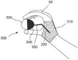
图1A示出不接地用户接口装置(UID)10的实施例。不接地用户接口装置10可包括具有多个区段的主体。图1A中所示出的实施例具有三个区段:第一区段20、第二区段30和第三区段40。主体可具有任何数目的区段。区段可具有不同的配置。区段可具有相同的配置。第一区段20可锥形化。第一区段20可提供表面以便于用户的手指抓紧用户接口装置10。第一区段20可波形化。第一区段20可包含针对手指的凹槽。第一区段20可以是不接地用户接口装置10的底部区段。涵盖第一区段20的其它配置。第二区段30可锥形化。第二区段30可以是不接地用户接口装置10的顶部区段。第三区段40可容纳磁性位置传感器,如本文所描述。不接地用户接口装置10可以是有线的(未示出)或无线的。电线可用于对用户接口装置10供电。电线可用于承载信号(例如,与UID 10的磁性位置传感器相关联的信号)。举例来说,电线可用于将信号承载到控制系统,如本文所描述。在一些实施例中,用户接口装置10可以是无线的。FIG. 1A shows an embodiment of an ungrounded user interface device (UID) 10 . Ungrounded
在一些实施例中,主体可以是卵形主体。主体可以是蛋形。主体可具有卵形形态。在一些实施例中,主体具有至少一个对称轴。在一些实施例中,主体的形状稍微偏离椭圆的形状,其中一端具有与另一端不同的曲率。第一区段20可近似于扁长球体的形状。第二区段30可近似于球形椭圆体的形状。第二区段30可近似于稍微扁球形球体。第一区段20和第二区段30可具有两个不同的半径。In some embodiments, the body may be an oval body. The body may be egg-shaped. The body may have an oval morphology. In some embodiments, the body has at least one axis of symmetry. In some embodiments, the shape of the body deviates slightly from the shape of an ellipse, with one end having a different curvature than the other. The
不接地用户接口装置10的主体可以是便携式的。在其它实施例中,本文所描述的用户接口装置不是便携式的。用户接口装置可耦合到支撑件。用户接口装置可耦合到从支撑件延伸的绳索。用户接口装置可耦合到机器人控制台。The body of the ungrounded
图1B示出人手50有利地握持这种不接地用户接口装置10的方式。用户接口装置10可以是有线的或无线的。为方便起见,图1B并未示出电线。除了能够借助用户的手腕移动用户接口装置10之外,用户接口装置10的形状使得用户接口装置10可仅借助用户的手指有效地进行移动。能够仅借助手指移动用户接口装置10的能力提供增强型灵巧性。FIG. 1B illustrates the manner in which such an ungrounded
不接地用户接口装置10的细长形状还可提供方向感和取向感。不接地用户接口装置10具有图1A中所示出的中心轴线15。中心轴线15从第一区段20延伸到第三区段40。中心轴线沿细长的不接地用户接口装置的纵向轴线延伸。在一些实施例中,中心轴线15是对称轴。在一些实施例中,机器人工具的纵向轴线可通过沿用户接口装置10的中心轴线15控制用户接口装置10进行控制。另外在多数情况下,用户接口装置10的中心轴线15可用来控制工具的滚动运动。The elongated shape of the ungrounded
不接地用户接口装置10可以是子弹形状。在一些实施例中,第一区段20可以是半球形的或大体上半球形的。在一些实施例中,第一区段20是圆锥形的或大体上圆锥形的。在一些实施例中,第一区段20是抛物线形的或大体上抛物线形的。第一区段20可分成一个或多个子区段。子区段可具有不同的形状和/或起到不同的功能。图1A示出第一区段20靠近不接地用户接口装置10的末端的子区段和第一区段20靠近唇缘25的子区段。靠近唇缘的子区段可安放在如本文所描述的腔室上方。子区段可具有不同的曲率半径。在一些实施例中,第二区段30是半球形的或大体上半球形的。在一些实施例中,第三区段40是圆柱形的或大体上圆柱形的。The ungrounded
不接地用户接口装置10包含可靠近用户的手的手掌握持的近端。不接地用户接口装置10包含远离用户的手掌指向的远端。用户接口装置10的中心轴线15从近端延伸到远端。中心轴线15还可被叫作细长轴线或对称轴。中心轴线15沿不接地用户接口装置10的长度。不接地用户接口装置10具有与细长轴线15横向(例如,以90度)延伸的横向轴线。横向轴线沿不接地用户接口装置10的宽度。不接地用户接口装置10具有沿细长轴线的细长维度和沿横向轴线的横向维度。在一些实施例中,细长维度大于横向维度。这形成长方形形状的不接地用户接口装置10。在一些实施例中,细长维度约是横向维度的两倍。涵盖其它维度(例如,细长维度约是横向维度的1.5倍,细长维度约是横向维度的3倍,细长维度约是横向维度的4倍等)。The ungrounded
当用户握持不接地用户接口装置10时,中心轴线15任选地大体上平行于用户的手指的轴线延伸。当用户握持不接地用户接口装置10时,中心轴线15大体上与用户的手的轴线对齐。当用户握持不接地用户接口装置10时,中心轴线15可任选地大体上与前臂的轴线对齐。When the user holds the ungrounded
不接地用户接口装置10包含沿横向平面的大体上圆形横截面,从而形成圆化外表面。这可以是第一区段20的外表面、第二区段30的外表面或者第一区段20和第二区段30的外表面。第一区段20可具有与第二区段30不同的曲率半径。此不同的形状可允许用户靠近手的手掌安放第一区段20,而远离手掌安放第二区段30。外表面允许用户借助用户的手旋转(例如,围绕中心轴线15)不接地用户接口装置10。外表面允许用户将不接地用户接口装置10旋转360度。用户可顺时针或逆时针转动不接地用户接口装置10。The ungrounded
不接地用户接口装置10的外表面具有至少一个表面以促进用户抓紧接口装置10。至少一个表面可以是唇缘25。唇缘25可围绕整个不接地用户接口装置10或不接地用户接口装置10的一部分延伸。The outer surface of the ungrounded
在使用时,不接地用户接口装置10的外表面可由用户下压,如本文所描述。举例来说,不接地用户接口装置10的外表面的至少一部分可由用户的手指挤压。不接地用户接口装置10可任选地包含本文所描述的腔室。腔室可用流体(例如,液体)填充。用户可从外表面下压(例如,通过借助他或她的手指在接口装置10的表面上推动)腔室。不接地用户接口装置10可任选地包含泵。泵可改变腔室的压力以向用户提供触觉反馈,如本文所描述。由于用户在用户接口装置10的外表面上按压而感测到的腔室中的压力由控制系统转换成末端执行器所施加的力。In use, the outer surface of the ungrounded
不接地用户接口装置10的大小允许用户借助用户的手平移不接地用户接口装置10。在一些实施例中,用户接口装置仅仅由用户的手支撑。The size of the ungrounded
不接地用户接口装置10可任选地包含一个或多个传感器。传感器可将关于不接地用户接口装置10的取向信息提供到控制系统。不接地用户接口装置10可向控制系统提供输入,从而将用户接口装置的运动转变成机器人臂的末端执行器的运动。The ungrounded
使用装置的方法可在图1B中示出。用户可如图所示握持用户接口装置10的主体。用户可借助手旋转主体的外表面。用户可借助手旋转和平移主体。设置在主体内的传感器在握持、旋转或平移步骤中的一个或多个期间可将关于用户接口装置的取向信息提供到控制系统。所述方法可包含以下步骤:将用户接口装置的运动转变成机器人臂的末端执行器的运动。所述方法可包含以下步骤:夹持主体的唇缘25。所述方法可包含以下步骤:下压主体的外表面。所述方法可包含以下步骤:将用户的手施予在主体的外表面上的压力转换成机器人臂的末端执行器所施加的力。所述方法可包含以下步骤:用户在用户接口装置的(例如,围绕中心轴线15)任何旋转位置处下压外表面。所述方法可包含以下步骤:用流体(例如,液体)填充主体的腔室。所述方法可包含以下步骤:从外表面下压腔室(例如,用户通过在主体的外表面上按压而下压腔室)。所述方法可包含以下步骤:将腔室的压力转换成机器人臂的末端执行器所施加的力。所述方法可包含以下步骤:借助泵改变腔室的压力以向用户提供触觉反馈(例如,经由腔室中显现且传达给夹持主体的用户的手的压力变化)。A method of using the device can be shown in Figure IB. The user may hold the main body of the
图2示出沿图1A中所示出的平面B-B的横截面。如本文所描述,不接地用户接口装置10可具有三个区段:第一区段20、第二区段30和第三区段40。在一些实施例中,促进抓紧的特征可设置在用户接口装置10的外表面上。图2示出唇缘25。用户可使用此唇缘25来抓紧用户接口装置10。例如唇缘25等特征可用来向用户提供位置或取向信息。Figure 2 shows a cross section along the plane B-B shown in Figure 1A. As described herein, the ungrounded
在图2中所示出的配置中,电线45从第三区段40延伸。电线45可耦合到磁性位置传感器130。磁性位置传感器130可类似于本领域中已知的磁性位置传感器。磁性位置传感器130可确定不接地用户接口装置10的位置。磁性位置传感器130可将位置数据传输到控制系统,如本文所描述。如本文所指出,可使用其它类型的传感器,包含但不限于无线传感器。另一组传感器可耦合到传感器和电子装置底座120。传感器和电子装置底座120可任选地容纳一个或多个传感器。传感器和电子装置底座120充当一个或多个传感器的底座。传感器和电子装置底座120使一个或多个传感器相对于彼此固持在固定位置中。在一些实施例中,传感器和电子装置底座120设置在不接地用户接口装置10的主体内。传感器和电子装置底座120可设置在第一区段20、第二区段30和/或第三区段40中。在一些实施例中,一个或多个传感器可任选地设置在不接地用户接口装置10的主体外。可耦合到传感器和电子装置底座120的传感器包含不限于陀螺仪和加速度计。陀螺仪和加速度计能够测量用户接口装置10的旋转和取向(例如,角取向)。传感器和电子装置底座120可包含至少一个陀螺仪。传感器和电子装置底座120可包含至少一个加速度计。传感器和电子装置底座120可包含至少一个磁力计。传感器和电子装置底座120可包含至少一个6DOF(自由度)传感器。传感器和电子装置底座120可包含至少一个惯性测量单元(IMU)。In the configuration shown in FIG. 2 , the
本领域中已知的任何传感器可耦合到传感器和电子装置底座120。不接地用户接口装置10可包含一个或多个传感器。一个或多个传感器可确定不接地用户接口装置10的位置和/或取向。一个或多个传感器可检测不接地用户接口装置10的运动。一个或多个传感器可确定用户是否正握持不接地用户接口装置10(例如,通过测量不接地用户接口装置10的表面的阻抗,如本文所描述)。一个或多个传感器可确定用户是否正对不接地用户接口装置10施加压力(例如,通过测量不接地用户接口装置10的腔室的压力,如本文所描述)。Any sensor known in the art may be coupled to the sensor and electronics base 120 . Ungrounded
在一些实施例中,不接地用户接口装置10包含电机100。可通过控制电机100的操作向用户提供触觉反馈。举例来说,可向用户提供电机100的开关次数和速度的信息。电机100可任选地是径向电机,如图所示。代替径向电机或除径向电机外,触觉反馈还可通过使用旋转质量块或振动电机而提供。不接地用户接口装置10可包含提供触觉反馈的一个或多个机构。触觉反馈可由电机100提供。触觉反馈可通过改变腔室的压力而提供,如本文所描述。触觉反馈可通过不接地用户接口装置10的振动提供。涵盖其它类型的反馈。不接地用户接口装置10可产生声音。举例来说,当末端执行器接近接头极限时,不接地用户接口装置10可产生声音。不接地用户接口装置10可发光。举例来说,当与控制系统和/或末端执行器通信时,不接地用户接口装置10可发光。In some embodiments, the ungrounded
在一些实施例中,电机100可向用户传达力或扭矩。电机100可向用户传达力,从而使得用户可借助由不接地用户接口装置10控制的末端执行器的纵向轴线对不接地用户接口装置10的中心轴线15重新取向。在用户移动不接地用户接口装置10时,中心轴线15可变得与末端执行器的纵向轴线不对齐。电机100可被启动以在不接地用户接口装置10内旋转。在一些实施例中,电机100控制旋转质量块。扭矩、力矩或力可由电机100产生。此触觉反馈可指示用户应对不接地用户接口装置10重新取向。此触觉反馈还可提供方向信息,用户应沿所述方向移动不接地用户接口装置10从而对不接地用户接口装置10重新取向。当不接地用户接口装置10与末端执行器不对齐或开始变得与末端执行器不对齐时,电机100可将信息传达给用户。In some embodiments, the
电机100在不接地用户接口装置10内自旋得越快,陀螺仪的效果就越大。电机将沿朝着使不接地用户接口装置10的中心轴线15与末端执行器的纵向轴线对齐的方向对用户的手指施加扭矩。当用户以使轴线不对齐的方式移动不接地用户接口装置10时,电机100将抵消或部分抵消用户的移动。电机100将促使用户不会沿使不接地用户接口装置10的轴线与末端执行器不对齐的方向移动。以此方式,不接地用户接口装置10将更加抵抗使中心轴线15与末端执行器的纵向轴线不对齐的干扰力。电机100可通过对用户提供力或扭矩而传达其它信息。在一些实施例中,电机100可通过施加施加力或扭矩传达接头极限。The faster the
用户接口装置所通常提供的一个功能是抓紧、固持或捏紧物体的能力。图1和2中所描述的不接地用户接口装置10可有利地提供以独特方式抓紧、固持或捏紧的能力。参考图2,示出腔室140的横截面。腔室140可预填充有一定压力的流体。在一些实施例中,流体是空气。腔室140还可具有压力传感器150。腔室140周向位于不接地用户接口装置10内。在其它实施例中,腔室140可围绕圆周的一部分(例如,45°圆周、90°圆周、135°圆周、180°圆周、225°圆周、270°圆周等)设置。One function typically provided by user interface devices is the ability to grasp, hold, or pinch objects. The ungrounded
借助此配置可实施抓紧或握持运动。用户可对沿腔室140的外表面的任何位置施加外部压力。在一些实施例中,腔室140包含在第一区段20的一部分内。在一些实施例中,腔室140远离第二区段30和/或第三区段40隔开。在一些实施例中,腔室140远离第一区段20的锥形末端隔开。压力传感器150可根据用户在腔室140上推动而感测压力变化。压力传感器150可将压力变化传达到超灵巧型机器人系统的控制系统。随后,成比例大小的抓紧或夹捏力可由与用户接口装置10相关联的末端执行器施加。Grasping or holding movements can be implemented with this configuration. The user may apply external pressure anywhere along the outer surface of the
在一些实施例中,腔室140可用于提供触觉反馈。图3示出用户接口装置10'。用户接口装置10'可具有本文关于用户接口装置10所描述的特征中的一些或全部。用户接口装置10'可包含微型泵160。微型泵160可耦合到传感器和电子装置底座120。微型泵160可经由如图所示的管腔连接到腔室140。腔室140内的压力可由微型泵160控制和调制。微型泵160可用流体填充腔室140以提高腔室140的压力。这可导致用户感觉到压力提高。用户接口装置10'可使腔室140通风以降低腔室140的压力。在一些实施例中,微型泵160可降低压力。这可导致用户感觉到压力降低。In some embodiments,
在一些使用方法中,末端执行器(未示出)耦合到一个或多个力传感器。末端执行器经受的力可转化成腔室140中的成比例压力。因此,如果末端执行器将会接触硬的解剖特征,那么腔室140内的压力可能会提高。那么操作员可能更加难以挤压用户接口装置10'。类似地,如果末端执行器将会接触软的解剖特征,那么用户接口装置10'的空气腔室内的压力可能会降低,从而使得操作员易于挤压用户接口装置10'。因此,以此方式通过调制腔室140中的压力可将触觉反馈提供给操作员。另外,如果末端执行器将会接触超灵巧型机器人系统的另一末端执行器或另一部分,那么腔室140内的压力可能也会提高。In some methods of use, an end effector (not shown) is coupled to one or more force sensors. The force experienced by the end effector can be translated into a proportional pressure in the
在相关概念上,调制压力的方法可用来传达与上文指定类型不同的其它类型的信息。在一些使用方法中,在操纵超灵巧型机器人系统的过程期间,操作员可操纵系统的一个或多个接头,使得这些接头在其操作极限下或靠近其操作极限进行操作。可控制和调制腔室140内的压力以指示此类操作极限。举例来说,用户接口装置10'的腔室140内的压力可变得振动。振动可警告操作员系统配置此时可能不是理想的。由此可见,腔室140可用于向用户传达不同类型的信息。In a related concept, methods of modulating pressure may be used to convey other types of information than those specified above. In some methods of use, during the process of manipulating a hyperdexterous robotic system, an operator may manipulate one or more joints of the system such that the joints operate at or near their operational limits. The pressure within
用户接口装置10、10'可由廉价材料(例如但不限于软橡胶和塑料)制成。传感器和电子装置也可以是廉价的,因此使得整个用户接口装置10、10'廉价。对用户接口装置10、10'使用廉价材料的另一优点在于本设计可在大小上缩放。因此,不同大小的用户接口装置10、10'可被制造成容纳用户的各种大小的手。在一些实施例中,用户接口装置10、10'可以是一次性组件(例如,供单次手术操作使用)。在手术之前,系统的准备和安装可包含以下步骤:打开包含无菌用户接口装置10、10'的包装。
所述方法可包含以下步骤:确保超灵巧型机器人系统的控制系统识别和接受来自用户接口装置10、10'的命令。所述方法可包含以下额外步骤:将用户接口装置10、10'耦合到超灵巧型机器人系统。就有线不接地用户接口装置而言,可存在连接电线的步骤。电线可源自超灵巧型机器人系统且其后耦合到用户接口装置10、10'。就无线不接地用户接口装置10、10'而言,可存在类似于使头戴式耳机与智能电话配对的步骤。举例来说,超灵巧型机器人系统可能需要将用户接口装置10、10'识别为控制器。用户可能必须键入输入或以其它方式将用户接口装置10、10'与超灵巧型机器人系统链接。此外,还可存在测定步骤,其中用户必须对用户接口装置10、10'进行某些操纵,从而使得超灵巧型机器人系统可适当地解译命令。The method may include the steps of ensuring that the control system of the hyperdexterous robotic system recognizes and accepts commands from the
图1到3描述用户接口装置10、10',其可被描述为独立的,原因在于所有电子装置和传感器可包含在用户接口装置10、10'的主体内。在一些实施例中,电源也包含在用户接口装置10、10'的主体内。多个电子组件(例如但不限于传感器(陀螺仪、加速度计等)、电机、泵、电源)可设置在用户接口装置10、10'的主体内。这可使用户接口装置10、10'变得沉重,从而可导致灵巧性损失。Figures 1 to 3 depict the
图4示出用户接口装置10"的实施例。用户接口装置10"可具有本文关于用户接口装置10、10'所描述的特征中的一些或全部。用户接口装置10"有利地重新分布用户接口装置10"的重量,从而使得灵巧性可得以维持。Figure 4 shows an embodiment of a
在图4中,操作员在他或她的身体上佩戴装置200。装置200可包含用于用户接口装置10"的各种组件的壳体。举例来说,装置200可容纳各种组件,包含但不限于电源(例如电池组)、处理器、传感器和其它电子装置。装置200还可包含微型泵,其类似于图3中所示出的微型泵160。装置200可以多种方式耦合到用户。图4示出将装置200耦合到用户身体的绑带210。装置200可耦合到用户的手腕。In Figure 4, the operator wears the
电缆220可在装置200与用户接口装置10”的第一区段20之间延伸。电缆220可由一个或多个电线(未示出)构成。电线可用于将电力承载到用户接口装置10"。电线可用来在用户接口装置10"与装置200内的电子装置或传感器之间传递信号或信息。电缆220可包含供来自微型泵的流体(例如,空气)通过的柔性管腔。在此配置中,用户接口装置10"可以是重量轻的。由于可放置在装置200内的组件,因此用户接口装置10"可具有如本文关于用户接口装置10、10'所描述的功能。A
在一些实施例中,由于本文所论述的用户接口装置10、10'、10"并未如典型市售系统中接地,因此它们可能易于意外落下。此情形可能在操作员错误地使用户接口装置10、10'、10"落下时产生。用户接口装置10、10'、10"将会经受快的加速度。如果末端执行器跟着用户接口装置10、10'、10"且迅速加速,那么释放用户接口装置10、10'、10"可能导致患者受伤。In some embodiments, since the
为了防止患者受伤,可实施若干技术。用户接口装置10、10'、10”的加速度可被监测(例如,由UID 10、10'、10”中的一个或多个传感器,如加速度计)。如本文所指出,加速度可指示用户是否已使用户接口装置10、10'、10"落下。在一些技术中,如果加速度高于预设值,那么超灵巧型机器人系统的控制系统可防止或限制末端执行器的移动。在另一技术中,跨用户接口装置10、10'、10"的阻抗可被监测(例如,由UID 10、10'、10”中的一个或多个传感器)。阻抗可连续或每隔一定间隔进行测量。阻抗可指示用户是否接触用户接口装置10、10'、10"。如果阻抗超过阈值从而指示操作员与用户接口装置10、10'、10"的接触已丢失,那么超灵巧型机器人系统可防止或限制末端执行器的移动。举例来说,如果阻抗指示用户不再接触用户接口装置,那么超灵巧型机器人系统可限制来自用户接口装置10、10'、10"的任何输入运动。这些技术可结合使用,从而使得多个(例如,冗余的)技术可防止末端执行器由于用户接口装置10、10'、10"的运动而产生不想要的运动。To prevent patient injury, several techniques can be implemented. The acceleration of the
图5示出用户接口装置300的另一实施例。用户接口装置300可具有本文关于用户接口装置10、10'、10"所描述的特征中的一些或全部。用户接口装置300并不接地到平台或控制台。相反,用户接口装置300接地到操作员的身体。用户接口装置300是本文所描述的主体接地用户接口装置的实施例。图5示出人手50可有利地握持用户接口装置300的方式。在一些实施例中,操作员的手提供接地。用户接口装置300可包含接地装置310。接地装置310可以是便携式的。接地装置310可耦合到操作员的身体或以其它方式由操作员的身体携带。在一些实施例中,接地装置310耦合到操作员的手。在一些实施例中,接地装置310耦合到操作员的手掌。图5示出接地装置310可围绕手掌缠绕。接地装置310可以是绑带。接地装置310可以是局部手套。接地装置310可以是包围手的一部分的护套。FIG. 5 shows another embodiment of a
接地装置310可以是刚性的或柔性的。接地装置310可由材料(包含但不限于塑料)制成。在一些实施例中,塑料可定制模制到每个操作员的手。一个或多个链路可以串联或并联方式耦合到接地装置310。并联配置不在图5中示出。在图5中,第一链路耦合到接地装置310。第一链路320串联耦合到第二链路330。链路320、330可由轻量而刚性的杆构成。链路320、330可能够相对于彼此和/或相对于接地装置310移动。链路320、330可被认为是支撑用户接口装置300的支撑结构。
第二链路330可耦合到区段340。区段340在图5中以黑色示出。区段340如图所示可具有半球形形状。区段340可充当用于用户接口装置300的支撑件。在一些实施例中,用户接口装置300可呈球的形状。区段340可部分地包围用户接口装置300。用户接口装置300可在区段340内自由旋转。在一些实施例中,区段340包含内表面且用户接口装置300可相对于内表面旋转。借助此配置,操作员可滚动用户接口装置300。链路320、330相对于彼此的移动可提高自由度。更大体上由于链路320、330还有相对于彼此移动的能力,操作员可能够以全部六自由度移动用户接口装置300。另外,由于链路320、330可允许操作员朝向手掌拉动用户接口装置300,因此第七自由度也可供使用。这可用于各种目的,包含但不限于对末端执行器施加抓紧力。用户接口装置300可以是中空的和/或如本文所描述包含一个或多个腔室。在一些实施例中,装置200可包含用于用户接口装置300的各种组件的壳体,如本文所描述。装置200可耦合到接地装置310。用户接口装置300可以是重量轻的。用户接口装置300可以是廉价的,如本文所描述。用户接口装置300或用户接口装置300的部分可以是一次性的。举例来说,用户接口装置300和区段340可以是一次性的。接地装置310和/或链路320、330可重复使用和/或是非一次性的。在一些实施例中,可提供耦合第二链路330和区段310的便利方式,例如但不限于磁耦合。The
图5中所示出的配置具有许多优点。一个优点在于,由于用户接口装置300是主体接地系统,因此最小化或消除了其意外落下的可能性。另一优点在于,接地装置310可被用作附接装置200的位置,所述装置200包含例如但不限于电子装置、传感器和电源等组件。又一优点在于,接地装置310可与光学追踪传感器耦合,如以引用的方式并入的2014年3月13日提交的伴随公开国际申请号PCT/US2014/026115中所描述。光学追踪传感器可提供接地装置310和/或用户接口装置300相对于参照点(未示出)的位置。光学追踪传感器可利用来追踪接地装置310和/或用户接口装置300的位置。本领域中的技术人员可利用追踪本文所描述的用户接口装置的组件的其它合适的传感器、机构或方法。The configuration shown in Figure 5 has many advantages. One advantage is that because the
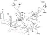
图6A、6B和7示出不接地用户接口装置的另一实施例。不接地用户接口装置400包含可靠近用户的手的手掌握持的近端,类似于图1B中所示出的装置。不接地用户接口装置400包含远离用户的手掌指向的远端。用户接口装置400的中心轴线475从近端延伸到远端。中心轴线475还可被叫作细长轴线或对称轴。中心轴线475沿不接地用户接口装置400的长度。不接地用户接口装置400具有与细长轴线475横向(例如,以90度)延伸的横向轴线。横向轴线沿不接地用户接口装置400的宽度。不接地用户接口装置400具有沿细长轴线的细长维度和沿横向轴线的横向维度。在一些实施例中,细长维度大于横向维度。这形成长方形形状的不接地用户接口装置400。6A, 6B and 7 illustrate another embodiment of an ungrounded user interface device. Ungrounded
不接地用户接口装置400包含沿横向轴线大体上圆形横截面,从而形成圆化外表面,如图7中所示出。外表面允许用户借助用户的手旋转不接地用户接口装置400。外表面允许用户使不接地用户接口装置400旋转360度。用户可顺时针或逆时针转动不接地用户接口装置400。Ungrounded
不接地用户接口装置400响应于参数可达到具体俯仰、偏转和/或滚动取向。在一些实施例中,参数是机器人工具或末端执行器的俯仰、偏转和/或滚动取向。在一些实施例中,参数是机器人末端执行器上的力。在一些实施例中,参数是一个或多个系统输入。系统输入可包含装置是处于驱动模式还是非驱动模式,如本文所描述。在非驱动模式下,末端执行器并不响应于如本文所描述来自用户接口装置的命令。Ungrounded
不接地用户接口装置400可包含位于不接地用户接口装置400内部的一个或多个致动器。致动器可被布置而成,从而使得它们实现不接地用户接口装置400的外表面或表层425相对于内部底盘440的运动。表层425是可变形的,从而使得底盘440在表层425内的运动可改变表层425的形状。改变表层425的形状的能力容许不接地用户接口装置400的取向可由软件控制。不接地用户接口装置400具有软件可控制的取向。Ungrounded
位于不接地用户接口装置400内部的一个或多个致动器可被布置成使得其配合移动导致不接地用户接口装置400的整个形状的变化。所述移动可以是扩张或收缩。所述移动可以是相对于表层425的任何移动。所述移动是由于不接地用户接口装置400的软件可控制的取向的结果。One or more actuators located inside the ungrounded
不接地用户接口装置400可维持中心轴线475与机器人系统的末端执行器或工具之间的对齐。在一些操作方法中,不接地用户接口装置400的取向被主动修改以保留不接地用户接口装置400和/或中心轴线475与用户接口装置400相关联的末端执行器的对齐。不接地用户接口装置400可包含外表面或表层425。不接地用户接口装置400可包含底盘440。底盘440可设置在表层425内。不接地用户接口装置400可具有卵形形状,如图6A中所示出。不接地用户接口装置400可具有独特的纵向轴线或中心轴线475。底盘440可在表层425内部移动。当底盘440在表层425内部移动时,用户可察觉到不接地用户接口装置400的中心轴线475的取向变化。以此方式,用户可获得来自不接地用户接口装置400的信息或反馈。The ungrounded
参考图6A,不接地用户接口装置400可具有一个或多个轮子。在所示出的实施例中,不接地用户接口装置400具有两个轮子430A、430B,但涵盖其它配置(例如,一个轮子、两个轮子、三个轮子、四个轮子等)。不接地用户接口装置400可具有一个或多个电机。在所示出的实施例中,不接地用户接口装置400具有两个电机435A、435B以用于驱动两个轮子430A、430B。涵盖其它配置。轮子430A、430B可任选地耦合到底盘440的一端。底盘440的另一端可任选地耦合到球形脚轮450。涵盖容许底盘440移动的其它装置或装置布置(例如,滚筒、轮子、脚轮等)。不接地用户接口装置400在图6B中示出为不含表层425。轮子430A、430B和脚轮450的配置是实施能够在包封表层425内部取向的双自由度系统的许多方式中的一种。Referring to Figure 6A, the ungrounded
在一些使用方法中,电机435A、435B由控制电子装置独立驱动。不接地用户接口装置400可包含一个或多个传感器,例如但不限于加速度计、陀螺仪、压力传感器。控制电子装置和传感器被示出为单个单元460,但涵盖其它配置。不接地用户接口装置400可包含电源(未示出)。控制电子装置和传感器可设置在不接地用户接口装置400内,且在一些实施例中设置在底盘440内或其上。在一些实施例中,不接地用户接口装置400的移动可由不接地用户接口装置400内的单元460控制。底盘440可由不接地用户接口装置400内的控制电子装置自驱动。在一些实施例中,单元460接收来自外部控制系统的控制信号。控制信号可操作致动器来改变中心轴线475的取向或进行如本文所描述的其它移动。底盘440可由不接地用户接口装置400外部的系统驱动。底盘440可由不接地用户接口装置400内或外部的控制信号驱动。In some methods of use, the
底盘440可在表层425内移动。两个箭头465和470指示底盘440可围绕中心轴线475倾斜(箭头465)或自旋(箭头470)。轮子430A、430B可允许底盘440相对于不接地用户接口装置400的表层425以双自由度取向。当底盘440在表层425内移动时,中心轴线475可倾斜或旋转。在底盘440的移动期间,表层425被拉伸且变形。用户可察觉到不接地用户接口装置400的取向在底盘440移动时发生改变。在一些使用方法中,用户将会察觉到他或她正握持的结构指向不同的方向。The
不接地用户接口装置400的表层425可以是可变形的。表层425可由柔性材料制成。一个实例是1/16"厚浇铸硅酮橡胶。变形性允许不接地用户接口装置400采用任何所希望的取向。变形性允许中心轴线475指向任何方向。变形性允许不接地用户接口装置400采用中心轴线475的任何俯仰、偏转和/或滚动。不接地用户接口装置400不接地但能够这些功能。The
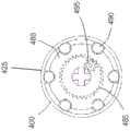
除了上文所描述的双自由度外,不接地用户接口装置400可任选地包含另一自由度。底盘440可耦合到环圈480。不接地用户接口装置400可具有一个或多个电机。在所示出的实施例中,不接地用户接口装置400具有电机495以用于旋转环圈480。环圈480可围绕底盘440旋转,从而导致环圈480在表层425内部移动。环圈480可具有接触表层425的内表面的外表面。环圈480的外表面可具有比轮子430A、430B的摩擦系数低的摩擦系数。当环圈480旋转时,底盘440不会相对于表层425旋转,而是相反,环圈480会相对于表层425旋转。In addition to the two degrees of freedom described above, the ungrounded
环圈480可具有位于环圈的外表面上的特征490。特征可包含脊或棘爪。用户在握持不接地用户接口装置400时可感受到特征490。特征490可以是滚筒或滚珠,从而在环圈480与表层425之间形成低摩擦系数。图7示出不接地用户接口装置400穿过环圈480的横截面。特征490被示出为接触表层425的滚珠。环圈480可包含内齿轮480。内齿轮485可由环圈电机495驱动。特征490可以是旋转不对称的或旋转对称的。额外的自由度可允许不接地用户接口装置400安放在任何所希望的取向上。额外的自由度可允许不接地用户接口装置400向用户提供关于位置(包含末端执行器的滚动位置)的反馈。在一些使用方法中,环圈480可在表层425内部旋转。用户可感觉到特征490的位置。用户可根据特征490的位置导出包含滚动信息的位置信息。不接地用户接口装置400可反映或模拟末端执行器的取向以向用户提供信息或反馈。
在替代实施例(未示出)中,表层425可固定到具有一个或多个致动器的内部结构。致动器可包含接触不接地用户接口装置400的表层425的致动器阵列。致动器可以是螺线管、导螺杆和电机、加压腔室等。致动器可以是小型的。致动器可响应于不接地用户接口装置400的所感测的取向而可控制地延伸或缩回。所感测的取向可由单元460中的传感器提供。所感测的取向可根据系统的状态(例如,驱动模式、非驱动模式等)提供。致动器可配合延伸和缩回从而与中心轴线475形成外部表层425的形状。致动器可配合延伸和缩回从而形成例如卵形形状等形状。致动器可被控制来形成形状取向在空间上是固定的错觉。形状可呈现为固定的,而不管用户旋转不接地用户接口装置400。In an alternate embodiment (not shown), the
不接地用户接口装置400可以多种方式进行控制。作为一个实例,不接地用户接口装置400可以驱动模式操作。在驱动模式下,用户主动命令末端执行器进行一些动作。不接地用户接口装置400可由用户移动从而移动末端执行器,如本文关于其它装置所描述。The ungrounded
作为一个实例,不接地用户接口装置400可以非驱动模式操作。在非驱动模式下,末端执行器不会跟着与不接地用户接口装置400相关联的不接地用户接口装置400的取向。在非驱动模式下,末端执行器是静止的。末端执行器仅在不接地用户接口装置400处于驱动模式时移动。底盘440可被驱动以便维持不接地用户接口装置400与末端执行器之间的对齐。在一些使用方法中,底盘440可对中心轴线475进行取向以便维持不接地用户接口装置400与末端执行器之间的对齐。当不接地用户接口装置400处于非驱动模式时,用户可重新放置他或她的手以返回到更加舒适的操作位置和取向。在非驱动模式下,轮子430A、430B可由电机435A、435B驱动,使得不接地用户接口装置400的中心轴线475将维持末端执行器的对齐(例如,俯仰和偏转)。如果包含环圈480,那么轮子430A、430B可由电机驱动,使得不接地用户接口装置400的中心轴线475将维持末端执行器的对齐(例如,俯仰、偏转和滚动)。用户在3D空间(例如,x、y、z平移)中自由移动不接地用户接口装置400。当用户以非驱动模式移动不接地用户接口装置400时,底盘440将移动来对中心轴线475进行取向。此效果类似于指南针,因为中心轴线475将持续与末端执行器的轴线对齐。中心轴线475或卵形主体的轴线将保持指向正确的取向,从而维持不接地用户接口装置400与静止末端执行器之间的对齐。As one example, the ungrounded
在驱动模式期间,不接地用户接口装置400可提供关于接头极限的反馈。不接地用户接口装置400以俯仰、偏转和滚动重新定位中心轴线475的能力可指示末端执行器的接头极限。当机器人工具在接头极限内操作时,不接地用户接口装置400可处于驱动模式。当不接地用户接口装置400在接头极限内操作时,不接地用户接口装置400中的电机不活动。用户的六自由度运动将引起末端执行器的移动。During the drive mode, the ungrounded
当达到接头极限中的一个时,不接地用户接口装置400的一个或多个电机将被主动驱动。不接地用户接口装置400的底盘440将被沿使中心轴线475与末端执行器的轴线对齐的方向驱动,而不管用户对进一步移动不接地用户接口装置400的尝试。不接地用户接口装置400可抵抗沿滚动、俯仰或偏转方向中的任一个的进一步移动。When one of the joint limits is reached, one or more motors of the ungrounded
举例来说,如果用户尝试使机器人工具滚动超过接头极限,那么可启动控制底盘440上的环圈480的电机。电机可使环圈480在空间中相对于操作员的参考系保持静止。用户将感觉到不接地用户接口装置400的表层425围绕静止环圈旋转。这将提供末端执行器已达到接头极限而不能旋转的反馈。当末端执行器碰到机器人工具的手腕的俯仰和偏转接头的接头极限时,可驱动不接地用户接口装置400的控制轮子430A、430B的其它电机435A、435B。当用户尝试使末端执行器的角度超过接头极限时,底盘440将停止在用户希望的方向上的旋转。当达到接头极限时,控制底盘440的电机将变得活动。底盘440可移动,使得底盘440的绝对取向恒定,而不管由用户握持的表层425的不断变化的取向。底盘440的绝对取向可由磁性追踪器、IMU等给定。这将提供末端执行器已达到接头极限而不能俯仰或偏转的反馈。在此操作模式下,不接地用户接口装置400提供机器人已达到特定角方向上的前进极限的直接触觉感觉。For example, if the user attempts to roll the robotic tool beyond the joint limit, the motors that control the
类似方法可用来向用户提供关于末端执行器碰到的力的反馈。举例来说,机器人工具的颚部可用来通过以下方式触摸组织:旋转鄂部直到其按压在组织上为止。在颚部碰到阻抗后,不接地用户接口装置400可通过将力传达给用户的方式进行驱动。在一些实施例中,提供力的量值和/或取向作为反馈。可对不接地用户接口装置400内部的驱动电机施加脉冲以提供反馈。在一些实施例中,底盘440按压在用户的手指上,且接着后退到底盘440的初始取向。底盘440的运动可沿末端执行器上的力向量的方向。底盘440的运动可在用户的参考系中。力向量的运动可在机器人相机的参考系中。前向运动可在更短的时间段中以比底盘440返回到其原始位置高的加速度执行。当底盘440冲击表层425时,用户的手指可能对底盘440的动量而不是底盘440的位置或振动敏感。在一些使用方法中,不接地用户接口装置400提高底盘440沿末端执行器上所施加的力的方向的速度且当底盘440返回到末端执行器的实际位置时降低速度。不接地用户接口装置400可能够以易于由用户通过用户的手指解译的方式传达力向量。所施加脉冲的运动的量值和/或频率可随末端执行器上的力的提高而提高。Similar methods can be used to provide feedback to the user about the force encountered by the end effector. For example, the jaw of a robotic tool can be used to touch tissue by rotating the jaw until it presses against the tissue. After the jaws encounter the impedance, the ungrounded
在一些实施例中,本文所描述的用户接口装置可具有用于改变主体的形状的装置。装置可以是本文所描述的底盘440。装置可以是一个或多个致动器(例如,一个致动器、两个致动器、三个致动器、四个致动器、多个致动器等)。一个或多个致动器可改变用户接口装置的主体的形状。在一些实施例中,装置可以是一个或多个压力腔室。压力腔室可选择性地以流体填充从而改变用户接口装置的形状。压力腔室的容积可基于进入一个或多个腔室的流体而提高或降低。在一些实施例中,形状变化包含对用户接口装置的主体的轴线进行重新取向。在一些实施例中,形状变化包含使用户接口装置的中心轴线与由用户接口装置控制的末端执行器的轴线对齐。In some embodiments, the user interface devices described herein may have means for changing the shape of the body. The device may be the
本文所描述的用户接口装置可控制末端执行器的运动。本文所描述的用户接口装置可映射到超灵巧型手术系统的任何区段。本文所描述的用户接口装置可控制机器人臂或机器人工具的不同区段。作为一个实例,用户接口装置可用来将把手重新定位在沿机器人臂的中间位置。本文所描述的用户接口装置可具有不同的操作模式以控制超灵巧型手术系统的各种组件。本文所描述的用户接口装置可映射到虚拟模拟工具运动。用户接口装置可控制超灵巧型手术系统的虚拟末端执行器或任何其它虚拟组件。本文所描述的用户接口装置可映射到非机器人物体。非机器人物体的实例包含器官或其它身体结构。外科医生可将用户接口装置映射到非机器人物体以接收关于非机器人物体的触觉反馈。The user interface devices described herein can control the movement of the end effector. The user interface devices described herein can be mapped to any section of the hyperdexterous surgical system. The user interface devices described herein can control different sections of a robotic arm or robotic tool. As one example, a user interface device may be used to reposition the handle in an intermediate position along the robotic arm. The user interface devices described herein may have different modes of operation to control various components of the hyperdexterous surgical system. The user interface devices described herein can be mapped to virtual simulation tool motion. The user interface device may control the virtual end effector or any other virtual component of the hyperdexterous surgical system. The user interface devices described herein can be mapped to non-robotic objects. Examples of non-robotic objects include organs or other body structures. The surgeon may map the user interface device to the non-robotic object to receive haptic feedback about the non-robotic object.
本文所描述的用户接口装置可具有非手术用途。用户接口装置可用于与3D虚拟世界交互。用户接口装置可映射到这些世界内的任何物体。用户接口装置可向用户提供关于用户虚拟上触摸的物体的触觉反馈。用户接口装置可用于计算机辅助绘图(CAD)程序输入。用户接口装置可提供虚拟触针或映射到另一工具。如本文所描述的用户接口装置改变形状的能力可提供额外的功能以便于用户接口装置的非手术用途。形状的改变可提供关于非手术用途的反馈。不断变化的形状可提供关于虚拟世界中碰到的物体的反馈。不断变化的形状可提供有关任务成功或失败的反馈。不断变化的形状可提供虚拟世界内的取向感或位置。其它模式的反馈(例如光和声)也可向用户提供反馈。The user interface devices described herein may have non-surgical uses. User interface devices may be used to interact with the 3D virtual world. User interface devices can be mapped to any object within these worlds. The user interface device may provide the user with haptic feedback regarding objects that the user virtually touches. The user interface device may be used for computer aided drafting (CAD) program input. The user interface device may provide a virtual stylus or map to another tool. The ability of a user interface device to change shape as described herein may provide additional functionality to facilitate non-surgical use of the user interface device. Changes in shape can provide feedback on non-surgical uses. The changing shape provides feedback on objects encountered in the virtual world. The changing shape provides feedback on the success or failure of the task. The changing shape provides a sense of orientation or position within the virtual world. Other modes of feedback, such as light and sound, may also provide feedback to the user.
使用不接地用户接口装置400的方法可包含控制不接地用户接口装置400内的致动器。致动器可以是控制一个或多个可移动特征的电机。致动器可用来对不接地用户接口装置400的中心轴线进行取向。中心轴线475的取向可对应于末端执行器的中心轴线的取向。不接地用户接口装置400的中心轴线475的取向可在用户的参考系中。末端执行器的轴线的取向可在摄像机馈送的参考系中。Methods of using the ungrounded
使用不接地用户接口装置400的方法可包含向用户提供反馈。中心轴线475的取向可提供末端执行器的接头极限的信息。不接地用户接口装置400可提供有关末端执行器碰到的力的反馈。Methods of using the ungrounded
在一些实施例中,系统可利用光学传感器。光学传感器可用来感测物体的接近度,很像下文描述的接近度传感器。在一些实施例中,光学传感器可追踪用户接口装置。涵盖光学传感器的其它用途。举例来说,在一些实施例中,光学传感器可位于用户接口装置300上。用户的手可能妨碍安装在用户接口装置300上的光学传感器。区段340可部分地包围用户接口装置300。区段340可能妨碍安装在用户接口装置300上的光学传感器。在一些实施例中,光学传感器可安装到身体的另一部分。光学传感器可安装到用户的手上。在一些实施例中,光学传感器可安装到接地装置310。接地装置310的位置可充当用户接口装置300的位置的代理。接地装置可具有更少的障碍物。接地装置310的移动(例如,平移、旋转)可充当用户接口装置300的移动的代理。在一些实施例中,光学传感器可安装到链路320、330上。In some embodiments, the system may utilize optical sensors. Optical sensors can be used to sense the proximity of objects much like the proximity sensors described below. In some embodiments, the optical sensor can track the user interface device. Covers other uses of optical sensors. For example, in some embodiments, an optical sensor may be located on the
如早先所描述,用户接口装置10、10'、10"、300具有多个传感器,包含但不限于接近度传感器和传感器阵列。传感器阵列是多个传感器。传感器阵列可具有相同或不同类型的传感器。可通过复制相同的传感器或不同的传感器而实现冗余。相同类型的传感器测量相同的参数且实现冗余。还可通过使用不同类型的传感器而实现冗余,其中测量了不同的参数。在进行测量之后,分析可允许检查导出的参数。As described earlier, the
接近度传感器是感测接近度传感器但未必触碰传感器的物体的传感器。在一些实施例中,接近度传感器是光学传感器。接近度传感器不需要是光学的,且涵盖其它类型的传感器。接近度传感器可商购获得。接近度传感器在本质上是电容的。接近度传感器提供感测物体是否接近用户接口装置10、10'、10"、300的能力。这在许多情形下可能是有利的。在一些实施例中,接近度传感器可感测握持用户接口装置10、10'、10"、300的手指的存在。如果未感测到物体(例如手指),那么控制系统可命令超灵巧型机器人系统进入安全状态。在安全状态下,超灵巧型机器人系统可限制来自用户接口装置10、10'、10"、300的任何运动输入。举例来说,末端执行器可保持静止在一定位置,而不是跟着用户接口装置10、10'、10"、300的运动。这可防止患者由于末端执行器的无意移动(例如,当用户无意地使用户接口装置10、10'、10”、200落下时)而受伤。在一些实施例中,接近度传感器可感测握持用户接口装置10、10'、10"、300的方式。举例来说,接近度传感器可感测用户正进行什么示意动作。示意动作接着可映射成用于控制系统的系统命令。举例来说,例如挤压用户接口装置10、10'、10"、300等示意动作可用来使相机聚焦。A proximity sensor is a sensor that senses objects that are in proximity to the sensor but not necessarily touching the sensor. In some embodiments, the proximity sensor is an optical sensor. Proximity sensors need not be optical, and other types of sensors are encompassed. Proximity sensors are commercially available. Proximity sensors are capacitive in nature. The proximity sensor provides the ability to sense whether an object is in proximity to the
用户接口装置10、10'、10"、300的多个传感器可用来提供冗余读数。在一些实施例中,冗余可确保超灵巧型机器人系统的安全操作。举例来说,接近度传感器和阻抗传感器的使用可提供冗余以便于检测用户是否正握持装置。The multiple sensors of the
用户接口装置10、10'、10"、300的多个传感器可用来提供功能冗余。在一些实施例中,与用户接口装置10、10'、10"、300相关联的传感器是不同的类型。用户接口装置10、10'、10"、300可利用分离冗余的概念。作为实例,6DOF传感器可设置在用户接口装置10、10'、10"、300内部。用户接口装置10、10'、10"、300还可包含测量取向的惯性测量单元(IMU)和测量平移的光学追踪器。在一些实施例中,传感器中的一个或多个可设置在用户接口装置10、10'、10"、300的主体外。举例来说,光学追踪器可耦合到接地装置310。Multiple sensors of the
6DOF传感器的故障可能导致末端执行器发生不当行为。为了提供功能冗余,另一6DOF传感器可放置在用户接口装置10、10'、10"、300内部。然而,惯性测量单元和光学追踪器可提供与发生故障的6DOF传感器相同的功能。惯性测量单元和光学追踪器中的每一个可提供分离冗余。惯性测量单元和光学追踪器一起可提供与发生故障的6DOF传感器一样完整的冗余功能。惯性测量单元和光学追踪器起作用,就好像第二6DOF传感器存在一样。惯性测量单元可提供6DOF传感器的取向读数的冗余。光学追踪器可提供6DOF传感器的平移组件的冗余。在一些实施例中,传感器可提供另一传感器的读数的冗余读数。在一些实施例中,传感器可提供另一传感器的读数的一部分的冗余读数。在一些实施例中,每个传感器可提供另一传感器的读数的冗余读数。在一些实施例中,每个传感器可提供另一传感器的读数的一部分的冗余读数。在一些实施例中,无需包含与传感器同一类型的第二传感器以实现冗余。Failure of the 6DOF sensor can lead to improper end effector behavior. To provide functional redundancy, another 6DOF sensor may be placed inside the
每个传感器具有不同的缺陷。举例来说,加速度计可经历漂移。光学传感器的视线可能被遮挡。在一些实施例中,用户接口装置10、10'、10"、300有利地通过合并一个或多个不同类型的传感器而缓和缺陷。在一些实施例中,控制系统将人手的几何结构考虑在内。控制系统可基于用户接口装置10、10'、10"、300相对于手的移动或位置而作出假设。Each sensor has different defects. For example, accelerometers may experience drift. The view of the optical sensor may be blocked. In some embodiments, the
系统的额外特征在2015年2月24日提交的美国临时号62/120,128和2015年7月30日提交的国际申请号PCT/US2015/042991中有描述,其中的每一个以全文引用的方式并入本文中,其应被视为本说明书的一部分。这些应用描述解耦操作员的手的耦合运动的方法。在一些实施例中,可通过使用额外追踪装置实现解耦。举例来说,图8示出根据一些实施例的具有将操作员的手的耦合运动解耦的多个传感器的超灵巧型手术系统。Additional features of the system are described in US Provisional No. 62/120,128, filed February 24, 2015, and International Application No. PCT/US2015/042991, filed July 30, 2015, each of which is incorporated by reference in its entirety. incorporated herein, it should be considered a part of this specification. These applications describe a method of decoupling the coupled motion of an operator's hand. In some embodiments, decoupling may be achieved through the use of additional tracking devices. For example, Figure 8 illustrates a hyperdexterous surgical system with multiple sensors that decouple the coupled motion of an operator's hand, according to some embodiments.
如图8中所示出,操作员20被发现借助用户接口装置50而操作系统。用户接口装置50可以是不接地的。用户接口装置50可具有本文所描述的用户接口装置(例如,用户接口装置10、10'、10"、300、400)的任何特征。操作员还可被发现耦合到装置1400'和1400"。在一些实施例中,这些装置位于操作员的手背上。在其它实施例中,这些装置可位于沿操作员手臂的某一其它位置处。在一些实施例中,装置1400'和1400"可包括一个或多个传感器(例如,用于磁性追踪的传感器、用于惯性感测的传感器等)。在其它实施例中,例如使用光学追踪的那些实施例中,装置1400'和1400"可不含有任何传感器,且可替代地包括一个或多个灯和/或反射表面。装置1400'和1400"可具有本文所描述的装置(包含装置200和接地装置300)的任何特征。As shown in FIG. 8 , the
在图8中还看到两个相机1410'和1410"。在一些实施例中,可看到相机1410'直接瞄准装置1400',且可看到相机1410"直接瞄准装置1400"。装置1400'和装置1400"可具有与相机1400'和1410"一起形成光学追踪系统的反射表面、灯、插销或滚珠。因此,相机1410'和装置1400'可追踪操作员20的左手位置,而相机1410"和装置1400"可追踪操作员的右手位置。尽管装置1400'和1400"被示出为位于操作员的手背处,但可选择其它位置(例如,位于用户接口装置50上或位于操作员的身体的其它位置上)。在一些实施例中,可颠倒装置1400'和1400"位置以及相机1410'和1410"的位置(例如,相机位于操作员的手背上,而装置被安装成直接瞄准相机)。在一些实施例中,可利用其它类型的传感器如磁性追踪系统或视觉追踪系统,其被配置成识别操作员的手而非附连于操作员的手或身体的特定装置或器械的形状。另外,可使用惯性感测(例如加速度计),其将不需要外部追踪装置如1410'和1410"的存在。Also seen in Figure 8 are two
就此实施例而言,当用户接口装置50的运动施加到末端执行器的运动时,可解耦和减少或消除用户接口装置50在操作员借助他或她的手指滚动用户接口装置50时可能经受的耦合平移运动。为了对此进一步解释,如果操作员滚动用户接口装置50(在一些实施例中,在使用一只手或一双手时是非物质的)例如以对组织施加缝合,根据上文论述,预期一些平移运动可耦合到用户接口装置50。然而,使用上文所描述的补充追踪系统或其它追踪系统也可测量平移运动。假设追踪系统测量用户接口装置50经历的相同平移运动,那么可从施加到末端执行器的运动中去除或消除耦合的平移运动。在数学术语中,如果用户接口装置50中的任一个的运动由

在通过操作员使用他或她的手指而使用户接口装置50经受滚动运动时(尽管其可经历相同的平移运动),装置1400'和1400"可不经历任何滚动运动。用户接口装置50还可通过由人手的运动学特性确定的函数而经历在数学上与用户接口装置50的平移运动有关的运动。因此,假设用户接口装置50的平移运动与传感器在手掌背上的平移运动相同,以下等式可写为:When the

其中


如在等式2中所指定,用户接口装置50的平移运动与装置在手掌背上的平移运动相同。在计算等式3中的最终输出时,可消除此分量。因此,具有仅经历平移运动的独立装置允许从用户接口装置运动中解耦此运动。As specified in
在一些实施例中,虽然两个相机1410'和1410"示出在图8中,但可仅需要一个相机。其它实施例可包含使用在本质上非光学的传感器。因此,传感器1400'和1400"可为各种类型,包含但不限于电磁传感器。此外,虽然用户接口装置50在图中的图形展示看起来像长管结构,但应理解在其它实施例中,其它形状是可能的。In some embodiments, although two
因此,可看出,借助以上概念,可提供一种用于取向的方法。此外,提供了一种将操作员的自然运动映射到机器人工具的具体运动的方法。这些方法的实施例可有利地改进系统的易用性。Thus, it can be seen that with the above concepts, a method for orientation can be provided. Furthermore, a method is provided to map the natural movements of the operator to the specific movements of the robotic tool. Embodiments of these methods may advantageously improve the usability of the system.
所述使用方法可包含以下步骤中的一或多个。用户可从无菌包装展开用户接口装置。用户可将电线插入用户接口装置中。用户可将电线插入超灵巧型机器人系统的控制系统中。用户可在用户接口装置与超灵巧型机器人系统之间连接电线。用户可无线连接用户接口装置和超灵巧型机器人系统的控制系统。用户可借助末端执行器校正用户接口装置。用户可实践在患者的身体外部移动末端执行器。用户可抓紧用户接口装置。用户接口装置可测量当用户接触用户接口装置时用户接口装置的表面上的阻抗。用户可将用户接口装置从一个位置移动到另一位置。用户接口装置从一个位置到另一位置的运动可使末端执行器从一个位置移动到另一位置。移动可以是相同距离或成比例距离。用户可围绕用户接口装置的中心轴线移动用户接口装置。用户接口装置的运动可围绕末端执行器的纵向轴线移动末端执行器。移动可以是围绕纵向轴线相同旋转度成比例度。用户可对用户接口装置施加力。力的施加可使末端执行器施加力。力可以是抓紧力。力的施加可以是相同大小的力或成比例大小的力。用户接口装置可借助压力传感器测量力。The method of use may include one or more of the following steps. The user can deploy the user interface device from the sterile package. The user may plug the wires into the user interface device. Users can plug wires into the hyperdexterous robotic system's control system. The user may connect wires between the user interface device and the hyperdexterous robotic system. The user can wirelessly connect the user interface device and the control system of the hyperdexterous robotic system. The user can calibrate the user interface device by means of the end effector. The user may practice moving the end effector outside the patient's body. The user may grasp the user interface device. The user interface device may measure the impedance on the surface of the user interface device when the user contacts the user interface device. The user may move the user interface device from one location to another. Movement of the user interface device from one position to another may move the end effector from one position to another. The movement can be the same distance or a proportional distance. A user can move the user interface device about a central axis of the user interface device. Movement of the user interface device can move the end effector about its longitudinal axis. The movement may be proportional to the same degree of rotation about the longitudinal axis. A user may apply force to the user interface device. The application of the force causes the end effector to apply the force. The force can be a grasping force. The application of the force can be the same amount of force or a proportional amount of force. The user interface device may measure force by means of a pressure sensor.
用户接口装置可向用户提供反馈。用户接口装置可提高用户接口装置的腔室的压力。用户接口装置可降低用户接口装置的腔室的压力。用户接口装置可当末端执行器接触硬的材料(例如骨或超灵巧型机器人系统的组件)时提高压力。用户接口装置可当末端执行器接触软的材料(例如组织)时降低压力。用户接口装置可产生声音。用户接口装置可当末端执行器达到移动极限时产生警告声音。用户接口装置可当末端执行器与另一物体碰撞或有可能与另一物体碰撞时产生警告声音。用户接口装置可当用户接口装置移动过快时产生警告声音。用户接口可发光。用户接口装置可当与末端执行器连通时发光。用户接口装置可发光作为警告。The user interface device may provide feedback to the user. The user interface device may increase the pressure of the chamber of the user interface device. The user interface device may depressurize the chamber of the user interface device. The user interface device can increase pressure when the end effector contacts hard materials, such as bone or components of hyperdexterous robotic systems. The user interface device can reduce pressure when the end effector contacts soft materials (eg, tissue). The user interface device may generate sound. The user interface device may generate a warning sound when the end effector reaches the limit of movement. The user interface device may generate a warning sound when the end effector collides or is likely to collide with another object. The user interface device may generate a warning sound when the user interface device moves too fast. The user interface can be illuminated. The user interface device may illuminate when in communication with the end effector. The user interface device may illuminate as a warning.
用户可将装置耦合到身体的一部分。装置可容纳用户接口装置的各种组件。装置可减轻用户接口装置的重量。用户可将装置耦合到他或她的手腕。用户可借助绑带将装置耦合到他或她的身体。A user may couple the device to a portion of the body. The device may house various components of the user interface device. The device may reduce the weight of the user interface device. The user may couple the device to his or her wrist. The user may couple the device to his or her body by means of straps.
用户可将用户接口装置与用户的身体的一部分耦合。用户可在总成的区段内旋转用户接口装置。用户可将区段耦合到一个或多个链路。一个或多个链路在其间可具有相对运动。用户可将一个或多个链路耦合到接地装置。用户可将接地装置与用户的身体的一部分耦合。接地装置可围绕用户的手掌缠绕。接地装置可以是绑带。用户接口装置可具有至少三个自由度。用户接口装置可具有至少四个自由度。用户接口装置可具有至少五个自由度。用户接口装置可具有至少六个自由度。用户接口装置可具有至少七个自由度。用户接口装置可具有在其控制下与末端执行器一样多的自由度。The user may couple the user interface device to a portion of the user's body. The user can rotate the user interface device within the segment of the assembly. A user can couple a segment to one or more links. One or more links may have relative motion therebetween. The user can couple one or more links to ground. The user may couple the grounding device to a portion of the user's body. The grounding device can wrap around the user's palm. The grounding device can be a strap. The user interface device may have at least three degrees of freedom. The user interface device may have at least four degrees of freedom. The user interface device may have at least five degrees of freedom. The user interface device may have at least six degrees of freedom. The user interface device may have at least seven degrees of freedom. The user interface device may have as many degrees of freedom as the end effector under its control.
现在可明显的是,本公开中所描述的用户接口装置扩展超灵巧型机器人系统的效用。操作员未必在一个位置处静止。借助本文所公开的高级用户接口装置,操作员可采用相对于患者最理想的位置。此外,操作员可在外科医生期间相对于患者改变他或她的位置。由于这些用户接口装置(例如进行手动和机器人手术的能力)而增强了超灵巧型机器人系统的许多益处。It is now apparent that the user interface devices described in this disclosure extend the utility of hyperdexterous robotic systems. The operator is not necessarily stationary at one location. With the advanced user interface devices disclosed herein, the operator can assume the most ideal position relative to the patient. Additionally, the operator may change his or her position relative to the patient during the surgeon. Many benefits of hyperdexterous robotic systems are enhanced by these user interface devices, such as the ability to perform manual and robotic surgery.
尽管本公开已在某些实施例和实例的背景下描述,但本领域的技术人员应理解,本公开延伸超过具体公开的实施例到其它替代实施例和/或本公开的用途和明显修改及等效物。另外,虽然已示出并详细描述了本公开的实施例的若干变化,但是本领域的技术人员将易于理解在本公开范围内的其它修改。此外,预期可进行实施例的具体特征和方面的各种组合或子组合并仍然落入本公开的范围内。举例来说,上文结合一个实施例描述的特征可与本文所描述的不同的实施例一起使用且所述组合仍落入本公开的范围内。应理解,所公开的实施例的各种特征和方面可彼此结合或替代以便形成本公开的实施例的不同模式。因此,预期本文中本公开的范围不应受上文所描述的特定实施例限制。因此,除非另行说明或除非明确不相容,否则本发明的每个实施例除了本文所描述的其基本特征外可包括如本文根据本文所公开的本发明的彼此实施例所描述的一个或多个特征。Although the present disclosure has been described in the context of certain embodiments and examples, those skilled in the art will appreciate that the present disclosure extends beyond the specifically disclosed embodiments to other alternative embodiments and/or uses and obvious modifications of the present disclosure and equivalent. Additionally, while several variations of the embodiments of the present disclosure have been shown and described in detail, other modifications that are within the scope of the present disclosure will be readily apparent to those skilled in the art. Furthermore, it is contemplated that various combinations or subcombinations of the specific features and aspects of the embodiments can be made and still fall within the scope of the present disclosure. For example, features described above in connection with one embodiment can be used with different embodiments described herein and still fall within the scope of this disclosure. It should be understood that the various features and aspects of the disclosed embodiments may be combined with or substituted for one another in order to form different modes of the disclosed embodiments. Therefore, it is not intended that the scope of the present disclosure herein be limited by the specific embodiments described above. Thus, unless otherwise stated or unless expressly incompatible, each embodiment of the present invention may include, in addition to its essential features described herein, one or more of the herein described in terms of each other's embodiments of the invention disclosed herein a feature.
结合特定方面、实施例或实例一起描述的特征、材料、特性或基团应被理解为可适用于在此区段或本说明书别处所描述的任何其它方面、实施例或实例,除非与之不相容。在本说明书中所披露的所有特征(包括任何所附权利要求书、摘要以及附图)和/或如此披露的任何方法或过程的所有步骤可以按任何组合的形式组合,这类特征和/或步骤中的至少一些相互排斥的组合除外。保护并不限于任何前述实施例的细节。保护扩展到本说明书(包括任何所附权利要求书、摘要以及附图)中所公开的特征的任何新颖特征或任何新颖组合,或扩展到如此公开的任何方法或过程的步骤的任何新颖步骤或任何新颖组合。Features, materials, characteristics or groups described in conjunction with a particular aspect, embodiment or instance should be understood to be applicable to any other aspect, embodiment or instance described in this section or elsewhere in this specification, unless otherwise inconsistent therewith compatible. All features disclosed in this specification (including any accompanying claims, abstract and drawings) and/or all steps of any method or process so disclosed may be combined in any combination, such features and/or Except for at least some mutually exclusive combinations of the steps. Protections are not limited to the details of any preceding embodiment. Protection extends to any novel feature or any novel combination of features disclosed in this specification (including any accompanying claims, abstract and drawings), or to any novel step of any method or process so disclosed or any novel combination.
此外,在本公开中在单独实施方案的上下文中描述的某些特征还可在单一实施方案中组合地实施。相反地,在单一实施方案的上下文中描述的各种特征还可单独地在多个实施方案中实施或以任何合适的子组合来实施。此外,尽管特征可在上文描述为以某些组合起作用,但在一些情况下,来自所要求的组合的一个或多个特征可从所述组合切离,且所述组合可被要求为子组合或子组合的变化。Furthermore, certain features that are described in this disclosure in the context of separate implementations can also be implemented in combination in a single implementation. Conversely, various features that are described in the context of a single implementation can also be implemented in multiple implementations separately or in any suitable subcombination. Furthermore, although features may be described above as functioning in certain combinations, in some cases one or more features from a claimed combination may be severed from that combination, and the combination may be claimed as Sub-combination or variation of sub-combination.
此外,虽然操作可以特定次序在图式中描绘或在说明书中描述,但此类操作无需以所示出的特定次序或以顺序次序进行,且无需进行所有步骤,以实现令人希望的结果。未经描绘或描述的其它操作可并入在实例方法和过程中。举例来说,可在所描述的操作中的任一个之前、之后、同时地或之间进行一或多个额外操作。此外,所述操作可在其它实施方案中重新布置或重新排序。本领域的技术人员应理解,在一些实施例中,所示出和/或所公开的过程中实际采取的步骤可不同于图中所示出的那些步骤。取决于实施例,可去除上文所描述的某些步骤,可添加其它步骤。此外,上文所公开的具体实施例的特征和特质可以不同方式组合以形成额外的实施例,所有额外的实施例落入本公开的范围内。并且,上文所描述的实施方案中的各种系统组件的分离不应被理解为在所有实施方案中要求此类分离,且应理解,所描述的组件和系统可大体上在一起整合在单一产品或封装到多个产品中。Furthermore, although operations may be depicted in the drawings or described in the specification in a particular order, such operations need not be performed in the particular order shown, or in a sequential order, and all steps need not be performed, to achieve desirable results. Other operations not depicted or described may be incorporated into the example methods and processes. For example, one or more additional operations may be performed before, after, concurrently with, or between any of the described operations. Furthermore, the operations may be rearranged or reordered in other implementations. It will be understood by those skilled in the art that, in some embodiments, the steps actually taken in the illustrated and/or disclosed processes may differ from those illustrated in the figures. Depending on the embodiment, some of the steps described above may be removed and other steps may be added. Furthermore, the features and characteristics of the specific embodiments disclosed above may be combined in different ways to form additional embodiments, all of which fall within the scope of the present disclosure. Also, the separation of the various system components in the above-described embodiments should not be construed as requiring such separation in all embodiments, and it should be understood that the described components and systems may be generally integrated together in a single product or packaged into multiple products.
出于本公开的目的,本文中描述了某些方面、优点和新颖特征。所有此类优点可不必根据任何具特定实施例来实现。因此,举例来说,本领域的技术人员将认识到,本公开可以实现如本文中所教示的一个优点或优点的群组的方式来实施或执行而无需必须实现如本文可教示或建议的其它优点。For the purposes of the present disclosure, certain aspects, advantages and novel features have been described herein. All such advantages may not necessarily be realized in accordance with any particular embodiment. Thus, for example, those skilled in the art will recognize that the present disclosure may be implemented or carried out in a manner that achieves one advantage or group of advantages as taught herein without necessarily achieving others as may be taught or suggested herein advantage.
除非确切地陈述是其它情况,或另外在如所使用的上下文内进行理解,否则条件性语言(例如,“可(can、could、might或may)”)一般旨在传达某些实施例包含而其它实施例并不包含某些特征、元件和/或步骤。因此,此条件性语言通常并非希望暗示特征、元件和/或步骤无论如何是一个或多个实施例所需要的,或者一个或多个实施例必需包含用于在具有或不具有用户输入或提示的情况下决定这些特征、元件和/或步骤是否包含于任一特定实施例中或有待于在任一特定实施例中进行的逻辑。Unless specifically stated otherwise, or otherwise understood within the context as used, conditional language (eg, "can, could, might, or may") is generally intended to convey that certain embodiments include Other embodiments do not contain certain features, elements and/or steps. Thus, this conditional language is generally not intended to imply that features, elements, and/or steps are in any way required by one or more embodiments, or that one or more embodiments necessarily contain for use with or without user input or prompting and/or logic to determine whether such features, elements and/or steps are included in or to be performed in any particular embodiment.
除非确切地陈述是其它情况,否则例如短语“X、Y和Z中的至少一个”等连接性语言在所使用的情形中一般另外理解为传达某一条目、项等可以是X、Y或Z中的任一个。因此,此类连接性语言并非大体上意图暗示某些实施例需要X中的至少一个、Y中的至少一个和Z中的至少一个的存在。Conjunctive language such as the phrase "at least one of X, Y, and Z" is generally otherwise understood in the context in which it is used to convey that an item, item, etc. can be X, Y, or Z unless specifically stated otherwise. any of the. Thus, such connectivity language is not generally intended to imply that certain embodiments require the presence of at least one of X, at least one of Y, and at least one of Z.
本文中所使用的程度语言,例如如本文中所使用的术语“大致”、“约”、“大体上”和“基本上”,表示仍进行所希望的功能或实现所希望的结果的接近所陈述的值、量或特性的值、量或特性。举例来说,术语“大致”、“约”、“大体上”和“基本上”可以是指所陈述的量的小于10%内、小于5%内、小于1%内、小于0.1%内和小于0.01%内的量。作为另一实例,在某些实施例中,术语“大体上平行”和“基本上平行”是指脱离精确平行小于或等于15度、10度、5度、3度、1度、0.1度或其它的值、量或特性。Language of degree used herein, such as the terms "substantially," "about," "substantially," and "substantially," as used herein means that a desired function is still performed or a approximation of a desired result is achieved The value, quantity or characteristic of a stated value, quantity or characteristic. For example, the terms "substantially," "about," "substantially," and "substantially" can mean within less than 10%, within less than 5%, within less than 1%, within less than 0.1%, and less than 0.01%. As another example, in certain embodiments, the terms "substantially parallel" and "substantially parallel" mean less than or equal to 15 degrees, 10 degrees, 5 degrees, 3 degrees, 1 degree, 0.1 degrees, or other value, quantity or characteristic.
本公开的范围并不意欲由在此区段或本说明书别处的优选实施例的具体公开内容限制,且可由如呈现在此区段或本说明书别处或如将来呈现的权利要求书限定。权利要求书的语言应广泛地给予权利要求书中采用的语言进行解释且不限于在本发明书中或在本申请的审批过程期间所描述的实例,所述实例应被理解为非排他性的。The scope of the present disclosure is not intended to be limited by the specific disclosure of the preferred embodiments in this section or elsewhere in this specification, and may be defined by the claims as presented in this section or elsewhere in this specification or as presented in the future. The language of the claims should be interpreted broadly to the language employed in the claims and should not be limited to the examples described in this specification or during the prosecution of this application, which examples are to be construed as non-exclusive.
Claims (38)
Applications Claiming Priority (3)
| Application Number | Priority Date | Filing Date | Title |
|---|---|---|---|
| US201562151596P | 2015-04-23 | 2015-04-23 | |
| US62/151,596 | 2015-04-23 | ||
| PCT/US2015/052354WO2016171757A1 (en) | 2015-04-23 | 2015-09-25 | Hyperdexterous surgical system user interface devices |
Publications (2)
| Publication Number | Publication Date |
|---|---|
| CN107708595A CN107708595A (en) | 2018-02-16 |
| CN107708595Btrue CN107708595B (en) | 2020-08-04 |
Family
ID=57144681
Family Applications (1)
| Application Number | Title | Priority Date | Filing Date |
|---|---|---|---|
| CN201580080006.7AExpired - Fee RelatedCN107708595B (en) | 2015-04-23 | 2015-09-25 | Ultra-dexterous surgical system user interface device |
Country Status (7)
| Country | Link |
|---|---|
| US (1) | US10617484B2 (en) |
| EP (1) | EP3285673A4 (en) |
| KR (1) | KR20170139655A (en) |
| CN (1) | CN107708595B (en) |
| AU (1) | AU2015392228B2 (en) |
| BR (1) | BR112017022721A2 (en) |
| WO (1) | WO2016171757A1 (en) |
Families Citing this family (150)
| Publication number | Priority date | Publication date | Assignee | Title |
|---|---|---|---|---|
| US11871901B2 (en) | 2012-05-20 | 2024-01-16 | Cilag Gmbh International | Method for situational awareness for surgical network or surgical network connected device capable of adjusting function based on a sensed situation or usage |
| US11504192B2 (en) | 2014-10-30 | 2022-11-22 | Cilag Gmbh International | Method of hub communication with surgical instrument systems |
| CN107708595B (en) | 2015-04-23 | 2020-08-04 | Sri国际公司 | Ultra-dexterous surgical system user interface device |
| ITUB20155057A1 (en) | 2015-10-16 | 2017-04-16 | Medical Microinstruments S R L | Robotic surgery set |
| JP6673684B2 (en) | 2015-12-11 | 2020-03-25 | 株式会社メディカロイド | Remote control device and remote operation system |
| US11345053B2 (en) | 2016-09-16 | 2022-05-31 | Verb Surgical Inc. | Belt termination and tensioning in a pulley arrangement for a robotic arm |
| US10568703B2 (en)* | 2016-09-21 | 2020-02-25 | Verb Surgical Inc. | User arm support for use in a robotic surgical system |
| KR102295241B1 (en)* | 2016-12-09 | 2021-08-30 | 버브 서지컬 인크. | User interface device for use in robotic surgery |
| WO2018202529A1 (en)* | 2017-05-02 | 2018-11-08 | Medivation Ag | A surgical instrument system |
| US11801098B2 (en) | 2017-10-30 | 2023-10-31 | Cilag Gmbh International | Method of hub communication with surgical instrument systems |
| US11317919B2 (en) | 2017-10-30 | 2022-05-03 | Cilag Gmbh International | Clip applier comprising a clip crimping system |
| US11510741B2 (en) | 2017-10-30 | 2022-11-29 | Cilag Gmbh International | Method for producing a surgical instrument comprising a smart electrical system |
| US11229436B2 (en) | 2017-10-30 | 2022-01-25 | Cilag Gmbh International | Surgical system comprising a surgical tool and a surgical hub |
| US11564756B2 (en) | 2017-10-30 | 2023-01-31 | Cilag Gmbh International | Method of hub communication with surgical instrument systems |
| US11026687B2 (en) | 2017-10-30 | 2021-06-08 | Cilag Gmbh International | Clip applier comprising clip advancing systems |
| US11911045B2 (en) | 2017-10-30 | 2024-02-27 | Cllag GmbH International | Method for operating a powered articulating multi-clip applier |
| US11291510B2 (en) | 2017-10-30 | 2022-04-05 | Cilag Gmbh International | Method of hub communication with surgical instrument systems |
| US11925373B2 (en) | 2017-10-30 | 2024-03-12 | Cilag Gmbh International | Surgical suturing instrument comprising a non-circular needle |
| US11311342B2 (en) | 2017-10-30 | 2022-04-26 | Cilag Gmbh International | Method for communicating with surgical instrument systems |
| US11666331B2 (en) | 2017-12-28 | 2023-06-06 | Cilag Gmbh International | Systems for detecting proximity of surgical end effector to cancerous tissue |
| US11424027B2 (en) | 2017-12-28 | 2022-08-23 | Cilag Gmbh International | Method for operating surgical instrument systems |
| US10918310B2 (en) | 2018-01-03 | 2021-02-16 | Biosense Webster (Israel) Ltd. | Fast anatomical mapping (FAM) using volume filling |
| US20190201112A1 (en) | 2017-12-28 | 2019-07-04 | Ethicon Llc | Computer implemented interactive surgical systems |
| US11304763B2 (en)* | 2017-12-28 | 2022-04-19 | Cilag Gmbh International | Image capturing of the areas outside the abdomen to improve placement and control of a surgical device in use |
| US11744604B2 (en) | 2017-12-28 | 2023-09-05 | Cilag Gmbh International | Surgical instrument with a hardware-only control circuit |
| US11389164B2 (en) | 2017-12-28 | 2022-07-19 | Cilag Gmbh International | Method of using reinforced flexible circuits with multiple sensors to optimize performance of radio frequency devices |
| US11559308B2 (en) | 2017-12-28 | 2023-01-24 | Cilag Gmbh International | Method for smart energy device infrastructure |
| US11786245B2 (en) | 2017-12-28 | 2023-10-17 | Cilag Gmbh International | Surgical systems with prioritized data transmission capabilities |
| US11026751B2 (en) | 2017-12-28 | 2021-06-08 | Cilag Gmbh International | Display of alignment of staple cartridge to prior linear staple line |
| US20190201142A1 (en) | 2017-12-28 | 2019-07-04 | Ethicon Llc | Automatic tool adjustments for robot-assisted surgical platforms |
| US11013563B2 (en) | 2017-12-28 | 2021-05-25 | Ethicon Llc | Drive arrangements for robot-assisted surgical platforms |
| US11308075B2 (en) | 2017-12-28 | 2022-04-19 | Cilag Gmbh International | Surgical network, instrument, and cloud responses based on validation of received dataset and authentication of its source and integrity |
| US11069012B2 (en) | 2017-12-28 | 2021-07-20 | Cilag Gmbh International | Interactive surgical systems with condition handling of devices and data capabilities |
| US11273001B2 (en) | 2017-12-28 | 2022-03-15 | Cilag Gmbh International | Surgical hub and modular device response adjustment based on situational awareness |
| US10892995B2 (en) | 2017-12-28 | 2021-01-12 | Ethicon Llc | Surgical network determination of prioritization of communication, interaction, or processing based on system or device needs |
| US20190201090A1 (en) | 2017-12-28 | 2019-07-04 | Ethicon Llc | Capacitive coupled return path pad with separable array elements |
| US11304745B2 (en) | 2017-12-28 | 2022-04-19 | Cilag Gmbh International | Surgical evacuation sensing and display |
| US11179175B2 (en) | 2017-12-28 | 2021-11-23 | Cilag Gmbh International | Controlling an ultrasonic surgical instrument according to tissue location |
| US11696760B2 (en) | 2017-12-28 | 2023-07-11 | Cilag Gmbh International | Safety systems for smart powered surgical stapling |
| US10892899B2 (en) | 2017-12-28 | 2021-01-12 | Ethicon Llc | Self describing data packets generated at an issuing instrument |
| US11304699B2 (en) | 2017-12-28 | 2022-04-19 | Cilag Gmbh International | Method for adaptive control schemes for surgical network control and interaction |
| US11464535B2 (en) | 2017-12-28 | 2022-10-11 | Cilag Gmbh International | Detection of end effector emersion in liquid |
| US10943454B2 (en) | 2017-12-28 | 2021-03-09 | Ethicon Llc | Detection and escalation of security responses of surgical instruments to increasing severity threats |
| US11234756B2 (en) | 2017-12-28 | 2022-02-01 | Cilag Gmbh International | Powered surgical tool with predefined adjustable control algorithm for controlling end effector parameter |
| US11202570B2 (en) | 2017-12-28 | 2021-12-21 | Cilag Gmbh International | Communication hub and storage device for storing parameters and status of a surgical device to be shared with cloud based analytics systems |
| US11324557B2 (en) | 2017-12-28 | 2022-05-10 | Cilag Gmbh International | Surgical instrument with a sensing array |
| US11056244B2 (en) | 2017-12-28 | 2021-07-06 | Cilag Gmbh International | Automated data scaling, alignment, and organizing based on predefined parameters within surgical networks |
| US11076921B2 (en) | 2017-12-28 | 2021-08-03 | Cilag Gmbh International | Adaptive control program updates for surgical hubs |
| US10966791B2 (en) | 2017-12-28 | 2021-04-06 | Ethicon Llc | Cloud-based medical analytics for medical facility segmented individualization of instrument function |
| WO2019133144A1 (en) | 2017-12-28 | 2019-07-04 | Ethicon Llc | Detection and escalation of security responses of surgical instruments to increasing severity threats |
| US11659023B2 (en) | 2017-12-28 | 2023-05-23 | Cilag Gmbh International | Method of hub communication |
| US10755813B2 (en) | 2017-12-28 | 2020-08-25 | Ethicon Llc | Communication of smoke evacuation system parameters to hub or cloud in smoke evacuation module for interactive surgical platform |
| US11284936B2 (en) | 2017-12-28 | 2022-03-29 | Cilag Gmbh International | Surgical instrument having a flexible electrode |
| US11571234B2 (en) | 2017-12-28 | 2023-02-07 | Cilag Gmbh International | Temperature control of ultrasonic end effector and control system therefor |
| US11291495B2 (en) | 2017-12-28 | 2022-04-05 | Cilag Gmbh International | Interruption of energy due to inadvertent capacitive coupling |
| US10944728B2 (en) | 2017-12-28 | 2021-03-09 | Ethicon Llc | Interactive surgical systems with encrypted communication capabilities |
| US11786251B2 (en) | 2017-12-28 | 2023-10-17 | Cilag Gmbh International | Method for adaptive control schemes for surgical network control and interaction |
| US11166772B2 (en) | 2017-12-28 | 2021-11-09 | Cilag Gmbh International | Surgical hub coordination of control and communication of operating room devices |
| US11051876B2 (en) | 2017-12-28 | 2021-07-06 | Cilag Gmbh International | Surgical evacuation flow paths |
| US11364075B2 (en) | 2017-12-28 | 2022-06-21 | Cilag Gmbh International | Radio frequency energy device for delivering combined electrical signals |
| US11464559B2 (en) | 2017-12-28 | 2022-10-11 | Cilag Gmbh International | Estimating state of ultrasonic end effector and control system therefor |
| US20190206569A1 (en) | 2017-12-28 | 2019-07-04 | Ethicon Llc | Method of cloud based data analytics for use with the hub |
| US11903601B2 (en) | 2017-12-28 | 2024-02-20 | Cilag Gmbh International | Surgical instrument comprising a plurality of drive systems |
| US11529187B2 (en) | 2017-12-28 | 2022-12-20 | Cilag Gmbh International | Surgical evacuation sensor arrangements |
| US11602393B2 (en) | 2017-12-28 | 2023-03-14 | Cilag Gmbh International | Surgical evacuation sensing and generator control |
| US20190201039A1 (en) | 2017-12-28 | 2019-07-04 | Ethicon Llc | Situational awareness of electrosurgical systems |
| US11832899B2 (en) | 2017-12-28 | 2023-12-05 | Cilag Gmbh International | Surgical systems with autonomously adjustable control programs |
| US11317937B2 (en) | 2018-03-08 | 2022-05-03 | Cilag Gmbh International | Determining the state of an ultrasonic end effector |
| US11540855B2 (en) | 2017-12-28 | 2023-01-03 | Cilag Gmbh International | Controlling activation of an ultrasonic surgical instrument according to the presence of tissue |
| US12396806B2 (en) | 2017-12-28 | 2025-08-26 | Cilag Gmbh International | Adjustment of a surgical device function based on situational awareness |
| US11857152B2 (en) | 2017-12-28 | 2024-01-02 | Cilag Gmbh International | Surgical hub spatial awareness to determine devices in operating theater |
| US11832840B2 (en) | 2017-12-28 | 2023-12-05 | Cilag Gmbh International | Surgical instrument having a flexible circuit |
| US10849697B2 (en) | 2017-12-28 | 2020-12-01 | Ethicon Llc | Cloud interface for coupled surgical devices |
| US11419667B2 (en) | 2017-12-28 | 2022-08-23 | Cilag Gmbh International | Ultrasonic energy device which varies pressure applied by clamp arm to provide threshold control pressure at a cut progression location |
| US12127729B2 (en) | 2017-12-28 | 2024-10-29 | Cilag Gmbh International | Method for smoke evacuation for surgical hub |
| US11410259B2 (en) | 2017-12-28 | 2022-08-09 | Cilag Gmbh International | Adaptive control program updates for surgical devices |
| US12376855B2 (en) | 2017-12-28 | 2025-08-05 | Cilag Gmbh International | Safety systems for smart powered surgical stapling |
| US11896322B2 (en) | 2017-12-28 | 2024-02-13 | Cilag Gmbh International | Sensing the patient position and contact utilizing the mono-polar return pad electrode to provide situational awareness to the hub |
| US11969216B2 (en) | 2017-12-28 | 2024-04-30 | Cilag Gmbh International | Surgical network recommendations from real time analysis of procedure variables against a baseline highlighting differences from the optimal solution |
| US11132462B2 (en) | 2017-12-28 | 2021-09-28 | Cilag Gmbh International | Data stripping method to interrogate patient records and create anonymized record |
| US12062442B2 (en) | 2017-12-28 | 2024-08-13 | Cilag Gmbh International | Method for operating surgical instrument systems |
| US11419630B2 (en) | 2017-12-28 | 2022-08-23 | Cilag Gmbh International | Surgical system distributed processing |
| US11266468B2 (en) | 2017-12-28 | 2022-03-08 | Cilag Gmbh International | Cooperative utilization of data derived from secondary sources by intelligent surgical hubs |
| US12096916B2 (en) | 2017-12-28 | 2024-09-24 | Cilag Gmbh International | Method of sensing particulate from smoke evacuated from a patient, adjusting the pump speed based on the sensed information, and communicating the functional parameters of the system to the hub |
| US11633237B2 (en) | 2017-12-28 | 2023-04-25 | Cilag Gmbh International | Usage and technique analysis of surgeon / staff performance against a baseline to optimize device utilization and performance for both current and future procedures |
| US10987178B2 (en) | 2017-12-28 | 2021-04-27 | Ethicon Llc | Surgical hub control arrangements |
| US11937769B2 (en) | 2017-12-28 | 2024-03-26 | Cilag Gmbh International | Method of hub communication, processing, storage and display |
| US11160605B2 (en) | 2017-12-28 | 2021-11-02 | Cilag Gmbh International | Surgical evacuation sensing and motor control |
| US11179208B2 (en) | 2017-12-28 | 2021-11-23 | Cilag Gmbh International | Cloud-based medical analytics for security and authentication trends and reactive measures |
| US11998193B2 (en) | 2017-12-28 | 2024-06-04 | Cilag Gmbh International | Method for usage of the shroud as an aspect of sensing or controlling a powered surgical device, and a control algorithm to adjust its default operation |
| US11818052B2 (en) | 2017-12-28 | 2023-11-14 | Cilag Gmbh International | Surgical network determination of prioritization of communication, interaction, or processing based on system or device needs |
| US11559307B2 (en) | 2017-12-28 | 2023-01-24 | Cilag Gmbh International | Method of robotic hub communication, detection, and control |
| US10695081B2 (en) | 2017-12-28 | 2020-06-30 | Ethicon Llc | Controlling a surgical instrument according to sensed closure parameters |
| US11147607B2 (en) | 2017-12-28 | 2021-10-19 | Cilag Gmbh International | Bipolar combination device that automatically adjusts pressure based on energy modality |
| US10932872B2 (en) | 2017-12-28 | 2021-03-02 | Ethicon Llc | Cloud-based medical analytics for linking of local usage trends with the resource acquisition behaviors of larger data set |
| US11864728B2 (en) | 2017-12-28 | 2024-01-09 | Cilag Gmbh International | Characterization of tissue irregularities through the use of mono-chromatic light refractivity |
| US11576677B2 (en) | 2017-12-28 | 2023-02-14 | Cilag Gmbh International | Method of hub communication, processing, display, and cloud analytics |
| US11096693B2 (en) | 2017-12-28 | 2021-08-24 | Cilag Gmbh International | Adjustment of staple height of at least one row of staples based on the sensed tissue thickness or force in closing |
| US11100631B2 (en) | 2017-12-28 | 2021-08-24 | Cilag Gmbh International | Use of laser light and red-green-blue coloration to determine properties of back scattered light |
| US11896443B2 (en) | 2017-12-28 | 2024-02-13 | Cilag Gmbh International | Control of a surgical system through a surgical barrier |
| US11423007B2 (en) | 2017-12-28 | 2022-08-23 | Cilag Gmbh International | Adjustment of device control programs based on stratified contextual data in addition to the data |
| US11589888B2 (en) | 2017-12-28 | 2023-02-28 | Cilag Gmbh International | Method for controlling smart energy devices |
| US11376002B2 (en) | 2017-12-28 | 2022-07-05 | Cilag Gmbh International | Surgical instrument cartridge sensor assemblies |
| US11678881B2 (en) | 2017-12-28 | 2023-06-20 | Cilag Gmbh International | Spatial awareness of surgical hubs in operating rooms |
| US11253315B2 (en) | 2017-12-28 | 2022-02-22 | Cilag Gmbh International | Increasing radio frequency to create pad-less monopolar loop |
| US11278281B2 (en) | 2017-12-28 | 2022-03-22 | Cilag Gmbh International | Interactive surgical system |
| US11612444B2 (en) | 2017-12-28 | 2023-03-28 | Cilag Gmbh International | Adjustment of a surgical device function based on situational awareness |
| US10758310B2 (en) | 2017-12-28 | 2020-09-01 | Ethicon Llc | Wireless pairing of a surgical device with another device within a sterile surgical field based on the usage and situational awareness of devices |
| US10898622B2 (en) | 2017-12-28 | 2021-01-26 | Ethicon Llc | Surgical evacuation system with a communication circuit for communication between a filter and a smoke evacuation device |
| US11311306B2 (en) | 2017-12-28 | 2022-04-26 | Cilag Gmbh International | Surgical systems for detecting end effector tissue distribution irregularities |
| US11446052B2 (en) | 2017-12-28 | 2022-09-20 | Cilag Gmbh International | Variation of radio frequency and ultrasonic power level in cooperation with varying clamp arm pressure to achieve predefined heat flux or power applied to tissue |
| US11257589B2 (en) | 2017-12-28 | 2022-02-22 | Cilag Gmbh International | Real-time analysis of comprehensive cost of all instrumentation used in surgery utilizing data fluidity to track instruments through stocking and in-house processes |
| US11304720B2 (en) | 2017-12-28 | 2022-04-19 | Cilag Gmbh International | Activation of energy devices |
| US11109866B2 (en) | 2017-12-28 | 2021-09-07 | Cilag Gmbh International | Method for circular stapler control algorithm adjustment based on situational awareness |
| US11969142B2 (en) | 2017-12-28 | 2024-04-30 | Cilag Gmbh International | Method of compressing tissue within a stapling device and simultaneously displaying the location of the tissue within the jaws |
| US11432885B2 (en) | 2017-12-28 | 2022-09-06 | Cilag Gmbh International | Sensing arrangements for robot-assisted surgical platforms |
| US11534196B2 (en) | 2018-03-08 | 2022-12-27 | Cilag Gmbh International | Using spectroscopy to determine device use state in combo instrument |
| US11259830B2 (en) | 2018-03-08 | 2022-03-01 | Cilag Gmbh International | Methods for controlling temperature in ultrasonic device |
| US11986233B2 (en) | 2018-03-08 | 2024-05-21 | Cilag Gmbh International | Adjustment of complex impedance to compensate for lost power in an articulating ultrasonic device |
| US12303159B2 (en) | 2018-03-08 | 2025-05-20 | Cilag Gmbh International | Methods for estimating and controlling state of ultrasonic end effector |
| US11213294B2 (en) | 2018-03-28 | 2022-01-04 | Cilag Gmbh International | Surgical instrument comprising co-operating lockout features |
| US10973520B2 (en) | 2018-03-28 | 2021-04-13 | Ethicon Llc | Surgical staple cartridge with firing member driven camming assembly that has an onboard tissue cutting feature |
| US11278280B2 (en) | 2018-03-28 | 2022-03-22 | Cilag Gmbh International | Surgical instrument comprising a jaw closure lockout |
| US11096688B2 (en) | 2018-03-28 | 2021-08-24 | Cilag Gmbh International | Rotary driven firing members with different anvil and channel engagement features |
| US11090047B2 (en) | 2018-03-28 | 2021-08-17 | Cilag Gmbh International | Surgical instrument comprising an adaptive control system |
| US11589865B2 (en) | 2018-03-28 | 2023-02-28 | Cilag Gmbh International | Methods for controlling a powered surgical stapler that has separate rotary closure and firing systems |
| US11207067B2 (en) | 2018-03-28 | 2021-12-28 | Cilag Gmbh International | Surgical stapling device with separate rotary driven closure and firing systems and firing member that engages both jaws while firing |
| US11471156B2 (en) | 2018-03-28 | 2022-10-18 | Cilag Gmbh International | Surgical stapling devices with improved rotary driven closure systems |
| US11219453B2 (en) | 2018-03-28 | 2022-01-11 | Cilag Gmbh International | Surgical stapling devices with cartridge compatible closure and firing lockout arrangements |
| IT201800005468A1 (en) | 2018-05-17 | 2019-11-17 | Robotic system for surgery, particularly microsurgery | |
| EP3787853B1 (en)* | 2018-06-15 | 2025-01-01 | Verb Surgical Inc. | User interface device having finger clutch |
| US11534246B2 (en)* | 2018-06-15 | 2022-12-27 | Verb Surgical Inc. | User input device for use in robotic surgery |
| US11135030B2 (en) | 2018-06-15 | 2021-10-05 | Verb Surgical Inc. | User interface device having finger clutch |
| US11504200B2 (en) | 2019-01-24 | 2022-11-22 | Verb Surgical Inc. | Wearable user interface device |
| US11369377B2 (en) | 2019-02-19 | 2022-06-28 | Cilag Gmbh International | Surgical stapling assembly with cartridge based retainer configured to unlock a firing lockout |
| US11317915B2 (en) | 2019-02-19 | 2022-05-03 | Cilag Gmbh International | Universal cartridge based key feature that unlocks multiple lockout arrangements in different surgical staplers |
| US11357503B2 (en) | 2019-02-19 | 2022-06-14 | Cilag Gmbh International | Staple cartridge retainers with frangible retention features and methods of using same |
| US11464511B2 (en) | 2019-02-19 | 2022-10-11 | Cilag Gmbh International | Surgical staple cartridges with movable authentication key arrangements |
| US11331100B2 (en) | 2019-02-19 | 2022-05-17 | Cilag Gmbh International | Staple cartridge retainer system with authentication keys |
| CN110772325B (en)* | 2019-02-21 | 2024-09-10 | 深圳市精锋医疗科技股份有限公司 | Handle and main operation desk |
| USD952144S1 (en) | 2019-06-25 | 2022-05-17 | Cilag Gmbh International | Surgical staple cartridge retainer with firing system authentication key |
| USD964564S1 (en) | 2019-06-25 | 2022-09-20 | Cilag Gmbh International | Surgical staple cartridge retainer with a closure system authentication key |
| USD950728S1 (en) | 2019-06-25 | 2022-05-03 | Cilag Gmbh International | Surgical staple cartridge |
| US20210259779A1 (en)* | 2020-02-20 | 2021-08-26 | Verb Surgical Inc. | Multi-camera user interface device calibration and tracking |
| US11696807B2 (en) | 2020-03-17 | 2023-07-11 | Verb Surgical Inc. | Drop detection of ungrounded master controller for a surgical robot |
| WO2022027879A1 (en)* | 2020-08-07 | 2022-02-10 | 山东威瑞外科医用制品有限公司 | Lightweight surgical robot |
| EP4070752A1 (en)* | 2021-04-09 | 2022-10-12 | MinMaxMedical | Computer-assisted surgery system |
| DE102021121673A1 (en)* | 2021-08-20 | 2023-02-23 | B. Braun New Ventures GmbH | Medical collaborative robot with adjustable robotic arm and control method |
| US12409550B2 (en)* | 2022-01-12 | 2025-09-09 | Mantis Robotics, Inc. | Robot system with casing elements |
| KR102846250B1 (en)* | 2022-10-11 | 2025-08-18 | 재단법인 아산사회복지재단 | Master device for remote intervention |
Citations (4)
| Publication number | Priority date | Publication date | Assignee | Title |
|---|---|---|---|---|
| CN101578845A (en)* | 2007-01-12 | 2009-11-11 | 索尼爱立信移动通讯有限公司 | Portable device with three-dimensional content-navigation systems interacting on opposing surfaces |
| CN102339148A (en)* | 2010-07-15 | 2012-02-01 | 索尼公司 | Input apparatus |
| US20120053448A1 (en)* | 2010-09-01 | 2012-03-01 | Case Western Reserve University | Intervention-independent scan plane control for mri |
| CN102750017A (en)* | 2011-04-06 | 2012-10-24 | 索尼公司 | Operation apparatus |
Family Cites Families (19)
| Publication number | Priority date | Publication date | Assignee | Title |
|---|---|---|---|---|
| US5339723A (en)* | 1993-09-30 | 1994-08-23 | Ethicon, Inc. | Pressurized fluid actuation system for amplifying operator input force in a surgical instrument |
| US5720742A (en)* | 1994-10-11 | 1998-02-24 | Zacharias; Jaime | Controller and actuating system for surgical instrument |
| USD375909S (en)* | 1995-01-06 | 1996-11-26 | Audiovox Corporation | Oval shaped remote control transmitter |
| US6270508B1 (en)* | 1998-10-26 | 2001-08-07 | Charles H. Klieman | End effector and instrument for endoscopic and general surgery needle control |
| US6594552B1 (en)* | 1999-04-07 | 2003-07-15 | Intuitive Surgical, Inc. | Grip strength with tactile feedback for robotic surgery |
| JP2005267174A (en)* | 2004-03-18 | 2005-09-29 | National Institute Of Advanced Industrial & Technology | Ball-type tactile device |
| KR100948095B1 (en)* | 2005-02-24 | 2010-03-16 | 노키아 코포레이션 | Motion-input device for a computing terminal and method of its operation |
| DE102007022120B4 (en)* | 2007-05-11 | 2019-09-19 | Deutsches Zentrum für Luft- und Raumfahrt e.V. | Griffin control unit |
| US20090022432A1 (en)* | 2007-07-19 | 2009-01-22 | Juan Carlos Unda | TV Latex Remote Cover |
| JP2009267643A (en)* | 2008-04-23 | 2009-11-12 | Smk Corp | Remote control transmitter |
| US8682489B2 (en)* | 2009-11-13 | 2014-03-25 | Intuitive Sugical Operations, Inc. | Method and system for hand control of a teleoperated minimally invasive slave surgical instrument |
| JP5704833B2 (en) | 2010-05-10 | 2015-04-22 | オリンパス株式会社 | Operation input device and manipulator system |
| US9198714B2 (en)* | 2012-06-29 | 2015-12-01 | Ethicon Endo-Surgery, Inc. | Haptic feedback devices for surgical robot |
| DE102012112247A1 (en)* | 2012-12-13 | 2014-06-18 | How To Organize (H2O) Gmbh | Handle element and gripper input module for a haptic input system |
| JP6396987B2 (en) | 2013-03-15 | 2018-09-26 | エスアールアイ インターナショナルSRI International | Super elaborate surgical system |
| KR20140121581A (en)* | 2013-04-08 | 2014-10-16 | 삼성전자주식회사 | Surgical robot system |
| TWM499122U (en)* | 2014-10-31 | 2015-04-21 | Mei Chi Na Hsinyen Co Ltd | Wireless tattooing device |
| CN107708595B (en) | 2015-04-23 | 2020-08-04 | Sri国际公司 | Ultra-dexterous surgical system user interface device |
| US20160279802A1 (en)* | 2016-06-08 | 2016-09-29 | Caterpillar Inc. | System for operating a robotic assembly |
- 2015
- 2015-09-25CNCN201580080006.7Apatent/CN107708595B/ennot_activeExpired - Fee Related
- 2015-09-25BRBR112017022721Apatent/BR112017022721A2/ennot_activeApplication Discontinuation
- 2015-09-25WOPCT/US2015/052354patent/WO2016171757A1/ennot_activeCeased
- 2015-09-25KRKR1020177033987Apatent/KR20170139655A/ennot_activeWithdrawn
- 2015-09-25AUAU2015392228Apatent/AU2015392228B2/ennot_activeCeased
- 2015-09-25EPEP15890149.6Apatent/EP3285673A4/ennot_activeWithdrawn
- 2017
- 2017-10-23USUS15/790,901patent/US10617484B2/enactiveActive
Patent Citations (4)
| Publication number | Priority date | Publication date | Assignee | Title |
|---|---|---|---|---|
| CN101578845A (en)* | 2007-01-12 | 2009-11-11 | 索尼爱立信移动通讯有限公司 | Portable device with three-dimensional content-navigation systems interacting on opposing surfaces |
| CN102339148A (en)* | 2010-07-15 | 2012-02-01 | 索尼公司 | Input apparatus |
| US20120053448A1 (en)* | 2010-09-01 | 2012-03-01 | Case Western Reserve University | Intervention-independent scan plane control for mri |
| CN102750017A (en)* | 2011-04-06 | 2012-10-24 | 索尼公司 | Operation apparatus |
Also Published As
| Publication number | Publication date |
|---|---|
| CN107708595A (en) | 2018-02-16 |
| WO2016171757A1 (en) | 2016-10-27 |
| EP3285673A4 (en) | 2019-06-05 |
| KR20170139655A (en) | 2017-12-19 |
| US10617484B2 (en) | 2020-04-14 |
| BR112017022721A2 (en) | 2018-07-17 |
| EP3285673A1 (en) | 2018-02-28 |
| AU2015392228A1 (en) | 2017-11-02 |
| US20180168759A1 (en) | 2018-06-21 |
| AU2015392228B2 (en) | 2020-04-16 |
Similar Documents
| Publication | Publication Date | Title |
|---|---|---|
| CN107708595B (en) | Ultra-dexterous surgical system user interface device | |
| US12048505B2 (en) | Master control device and methods therefor | |
| US11096746B2 (en) | User interface devices for use in robotic surgery | |
| US12329487B2 (en) | Master control device with finger grip sensing and methods therefor | |
| CN108882968B (en) | Computer-assisted teleoperation surgical system and method | |
| US12089911B2 (en) | User interface device having finger clutch | |
| US11504200B2 (en) | Wearable user interface device | |
| KR20150097238A (en) | Master device for surgical robot and control method thereof | |
| Low et al. | A review of master–slave robotic systems for surgery | |
| JP2023052783A (en) | USER INTERFACE DEVICE HAVING FINGER GRIP | |
| CN115605155A (en) | Control interface and robot system comprising such a control interface | |
| JP5872280B2 (en) | Force vector transmission device and method | |
| EP4572696A1 (en) | Control system of a surgical robot |
Legal Events
| Date | Code | Title | Description |
|---|---|---|---|
| PB01 | Publication | ||
| PB01 | Publication | ||
| SE01 | Entry into force of request for substantive examination | ||
| SE01 | Entry into force of request for substantive examination | ||
| GR01 | Patent grant | ||
| GR01 | Patent grant | ||
| CF01 | Termination of patent right due to non-payment of annual fee | ||
| CF01 | Termination of patent right due to non-payment of annual fee | Granted publication date:20200804 Termination date:20210925 |