CN107708570B - Monitoring system, method and device - Google Patents
Monitoring system, method and deviceDownload PDFInfo
- Publication number
- CN107708570B CN107708570BCN201580081329.8ACN201580081329ACN107708570BCN 107708570 BCN107708570 BCN 107708570BCN 201580081329 ACN201580081329 ACN 201580081329ACN 107708570 BCN107708570 BCN 107708570B
- Authority
- CN
- China
- Prior art keywords
- atrium
- ventricle
- systolic
- time
- atrial
- Prior art date
- Legal status (The legal status is an assumption and is not a legal conclusion. Google has not performed a legal analysis and makes no representation as to the accuracy of the status listed.)
- Active
Links
Images


Classifications
- A—HUMAN NECESSITIES
- A61—MEDICAL OR VETERINARY SCIENCE; HYGIENE
- A61B—DIAGNOSIS; SURGERY; IDENTIFICATION
- A61B8/00—Diagnosis using ultrasonic, sonic or infrasonic waves
- A61B8/52—Devices using data or image processing specially adapted for diagnosis using ultrasonic, sonic or infrasonic waves
- A61B8/5215—Devices using data or image processing specially adapted for diagnosis using ultrasonic, sonic or infrasonic waves involving processing of medical diagnostic data
- A61B8/5238—Devices using data or image processing specially adapted for diagnosis using ultrasonic, sonic or infrasonic waves involving processing of medical diagnostic data for combining image data of patient, e.g. merging several images from different acquisition modes into one image
- A61B8/5261—Devices using data or image processing specially adapted for diagnosis using ultrasonic, sonic or infrasonic waves involving processing of medical diagnostic data for combining image data of patient, e.g. merging several images from different acquisition modes into one image combining images from different diagnostic modalities, e.g. ultrasound and X-ray
- A—HUMAN NECESSITIES
- A61—MEDICAL OR VETERINARY SCIENCE; HYGIENE
- A61B—DIAGNOSIS; SURGERY; IDENTIFICATION
- A61B5/00—Measuring for diagnostic purposes; Identification of persons
- A61B5/24—Detecting, measuring or recording bioelectric or biomagnetic signals of the body or parts thereof
- A61B5/316—Modalities, i.e. specific diagnostic methods
- A61B5/318—Heart-related electrical modalities, e.g. electrocardiography [ECG]
- A—HUMAN NECESSITIES
- A61—MEDICAL OR VETERINARY SCIENCE; HYGIENE
- A61B—DIAGNOSIS; SURGERY; IDENTIFICATION
- A61B5/00—Measuring for diagnostic purposes; Identification of persons
- A61B5/24—Detecting, measuring or recording bioelectric or biomagnetic signals of the body or parts thereof
- A61B5/316—Modalities, i.e. specific diagnostic methods
- A61B5/318—Heart-related electrical modalities, e.g. electrocardiography [ECG]
- A61B5/339—Displays specially adapted therefor
- A—HUMAN NECESSITIES
- A61—MEDICAL OR VETERINARY SCIENCE; HYGIENE
- A61B—DIAGNOSIS; SURGERY; IDENTIFICATION
- A61B8/00—Diagnosis using ultrasonic, sonic or infrasonic waves
- A—HUMAN NECESSITIES
- A61—MEDICAL OR VETERINARY SCIENCE; HYGIENE
- A61B—DIAGNOSIS; SURGERY; IDENTIFICATION
- A61B8/00—Diagnosis using ultrasonic, sonic or infrasonic waves
- A61B8/08—Clinical applications
- A61B8/0883—Clinical applications for diagnosis of the heart
- A—HUMAN NECESSITIES
- A61—MEDICAL OR VETERINARY SCIENCE; HYGIENE
- A61B—DIAGNOSIS; SURGERY; IDENTIFICATION
- A61B8/00—Diagnosis using ultrasonic, sonic or infrasonic waves
- A61B8/46—Ultrasonic, sonic or infrasonic diagnostic devices with special arrangements for interfacing with the operator or the patient
- A61B8/461—Displaying means of special interest
- A61B8/463—Displaying means of special interest characterised by displaying multiple images or images and diagnostic data on one display
- A—HUMAN NECESSITIES
- A61—MEDICAL OR VETERINARY SCIENCE; HYGIENE
- A61B—DIAGNOSIS; SURGERY; IDENTIFICATION
- A61B8/00—Diagnosis using ultrasonic, sonic or infrasonic waves
- A61B8/46—Ultrasonic, sonic or infrasonic diagnostic devices with special arrangements for interfacing with the operator or the patient
- A61B8/467—Ultrasonic, sonic or infrasonic diagnostic devices with special arrangements for interfacing with the operator or the patient characterised by special input means
- A61B8/468—Ultrasonic, sonic or infrasonic diagnostic devices with special arrangements for interfacing with the operator or the patient characterised by special input means allowing annotation or message recording
- A—HUMAN NECESSITIES
- A61—MEDICAL OR VETERINARY SCIENCE; HYGIENE
- A61B—DIAGNOSIS; SURGERY; IDENTIFICATION
- A61B8/00—Diagnosis using ultrasonic, sonic or infrasonic waves
- A61B8/52—Devices using data or image processing specially adapted for diagnosis using ultrasonic, sonic or infrasonic waves
- A61B8/5207—Devices using data or image processing specially adapted for diagnosis using ultrasonic, sonic or infrasonic waves involving processing of raw data to produce diagnostic data, e.g. for generating an image
- A—HUMAN NECESSITIES
- A61—MEDICAL OR VETERINARY SCIENCE; HYGIENE
- A61B—DIAGNOSIS; SURGERY; IDENTIFICATION
- A61B8/00—Diagnosis using ultrasonic, sonic or infrasonic waves
- A61B8/52—Devices using data or image processing specially adapted for diagnosis using ultrasonic, sonic or infrasonic waves
- A61B8/5215—Devices using data or image processing specially adapted for diagnosis using ultrasonic, sonic or infrasonic waves involving processing of medical diagnostic data
- A61B8/5223—Devices using data or image processing specially adapted for diagnosis using ultrasonic, sonic or infrasonic waves involving processing of medical diagnostic data for extracting a diagnostic or physiological parameter from medical diagnostic data
- G—PHYSICS
- G16—INFORMATION AND COMMUNICATION TECHNOLOGY [ICT] SPECIALLY ADAPTED FOR SPECIFIC APPLICATION FIELDS
- G16H—HEALTHCARE INFORMATICS, i.e. INFORMATION AND COMMUNICATION TECHNOLOGY [ICT] SPECIALLY ADAPTED FOR THE HANDLING OR PROCESSING OF MEDICAL OR HEALTHCARE DATA
- G16H50/00—ICT specially adapted for medical diagnosis, medical simulation or medical data mining; ICT specially adapted for detecting, monitoring or modelling epidemics or pandemics
- G16H50/30—ICT specially adapted for medical diagnosis, medical simulation or medical data mining; ICT specially adapted for detecting, monitoring or modelling epidemics or pandemics for calculating health indices; for individual health risk assessment
- A—HUMAN NECESSITIES
- A61—MEDICAL OR VETERINARY SCIENCE; HYGIENE
- A61B—DIAGNOSIS; SURGERY; IDENTIFICATION
- A61B5/00—Measuring for diagnostic purposes; Identification of persons
- A61B5/72—Signal processing specially adapted for physiological signals or for diagnostic purposes
- A61B5/7271—Specific aspects of physiological measurement analysis
- A61B5/7285—Specific aspects of physiological measurement analysis for synchronizing or triggering a physiological measurement or image acquisition with a physiological event or waveform, e.g. an ECG signal
- A—HUMAN NECESSITIES
- A61—MEDICAL OR VETERINARY SCIENCE; HYGIENE
- A61B—DIAGNOSIS; SURGERY; IDENTIFICATION
- A61B8/00—Diagnosis using ultrasonic, sonic or infrasonic waves
- A61B8/13—Tomography
- A61B8/14—Echo-tomography
- A—HUMAN NECESSITIES
- A61—MEDICAL OR VETERINARY SCIENCE; HYGIENE
- A61B—DIAGNOSIS; SURGERY; IDENTIFICATION
- A61B8/00—Diagnosis using ultrasonic, sonic or infrasonic waves
- A61B8/48—Diagnostic techniques
- A61B8/486—Diagnostic techniques involving arbitrary m-mode
- A—HUMAN NECESSITIES
- A61—MEDICAL OR VETERINARY SCIENCE; HYGIENE
- A61B—DIAGNOSIS; SURGERY; IDENTIFICATION
- A61B8/00—Diagnosis using ultrasonic, sonic or infrasonic waves
- A61B8/52—Devices using data or image processing specially adapted for diagnosis using ultrasonic, sonic or infrasonic waves
- A61B8/5284—Devices using data or image processing specially adapted for diagnosis using ultrasonic, sonic or infrasonic waves involving retrospective matching to a physiological signal
- A—HUMAN NECESSITIES
- A61—MEDICAL OR VETERINARY SCIENCE; HYGIENE
- A61B—DIAGNOSIS; SURGERY; IDENTIFICATION
- A61B8/00—Diagnosis using ultrasonic, sonic or infrasonic waves
- A61B8/54—Control of the diagnostic device
- A61B8/543—Control of the diagnostic device involving acquisition triggered by a physiological signal
Landscapes
- Health & Medical Sciences (AREA)
- Life Sciences & Earth Sciences (AREA)
- Engineering & Computer Science (AREA)
- Medical Informatics (AREA)
- Public Health (AREA)
- General Health & Medical Sciences (AREA)
- Biomedical Technology (AREA)
- Pathology (AREA)
- Heart & Thoracic Surgery (AREA)
- Animal Behavior & Ethology (AREA)
- Veterinary Medicine (AREA)
- Surgery (AREA)
- Molecular Biology (AREA)
- Physics & Mathematics (AREA)
- Biophysics (AREA)
- Nuclear Medicine, Radiotherapy & Molecular Imaging (AREA)
- Radiology & Medical Imaging (AREA)
- Cardiology (AREA)
- Computer Vision & Pattern Recognition (AREA)
- Physiology (AREA)
- Databases & Information Systems (AREA)
- Data Mining & Analysis (AREA)
- Epidemiology (AREA)
- Primary Health Care (AREA)
- Ultra Sonic Daignosis Equipment (AREA)
Abstract
Description
Translated fromChinese技术领域technical field
本发明涉及一种医疗设备,尤其涉及一种用于对心脏的周期性运动进行监测的监护系统。The present invention relates to a medical device, in particular to a monitoring system for monitoring the periodic motion of the heart.
背景技术Background technique
通常情况下,通过心电监护设备来监测心脏的周期性运动情况,并根据心电图对患者进行诊断,例如对心律失常、心脏夺获以及电机械分离的诊断。但在临床发现以下问题:Usually, the periodic motion of the heart is monitored by an ECG monitoring device, and the patient is diagnosed based on the ECG, such as the diagnosis of arrhythmia, cardiac capture, and electromechanical dissociation. However, the following problems were found clinically:
心电监护在心律失常的监护方面存在不准确性,比如当病人发生房颤时,可能存在杂波、电阻以及体位变动的干扰,进而加大了心电监护的不准确性。ECG monitoring is inaccurate in the monitoring of arrhythmias. For example, when a patient develops atrial fibrillation, there may be interference from clutter, resistance, and body position changes, which further increases the inaccuracy of ECG monitoring.
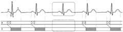
在一些特殊情况下,如体外起搏时,单纯的依靠心电图对心脏的夺获情况判断不准确。因为体外起搏的心电信号电压高低不一,电压较低的QRS波容易被漏检;电压过高时则存在过感知的问题,比如当出现高大的T波时,甚至可能导致心率的翻倍;另外,一些起搏波与后续波相距很近,后续波可能被误读为心脏夺获产生的QRS波(如图1所示),图中黑色标记处为起搏信号,后面的波形不是夺获产生的QRS波;但是,由于起搏波与此波相距很近,因此容易被误读为夺获产生的QRS波群,进而造成心脏被夺获的误判。因此,依靠心电无法准确判断心脏的夺获情况。In some special cases, such as external pacing, it is inaccurate to rely solely on ECG to judge the heart capture situation. Because the voltage of the ECG signal of external pacing varies, the QRS wave with lower voltage is easy to be missed; when the voltage is too high, there is a problem of over-sensing, such as when a tall T wave appears, it may even lead to an increase in the heart rate. In addition, some pacing waves are very close to the follow-up wave, and the follow-up wave may be misinterpreted as the QRS complex generated by cardiac capture (as shown in Figure 1). The black mark in the figure is the pacing signal, and the following waveform It is not the captured QRS complex; however, because the pacing wave is very close to this wave, it is easy to be misinterpreted as the captured QRS complex, resulting in a misjudgment that the heart is captured. Therefore, relying on ECG cannot accurately determine the capture of the heart.
另外,临床对于电机械分离(Electrical mechanical dissociation,EMD)的诊断,主要是结合病人的体征(如无心音、脉搏、呼吸和血压等)以及心电图的表现(如窦性、规律的、P-QRS-T顺序发生的各时段、电压正常的心电图形等)进行综合判定。病人心脏电活动可以通过心电图直接显示,而病人心脏的机械活动情况则是通过病人的体征间接显示,例如脉搏、呼吸和血压可以通过病人监护仪进行实时监测,而心音则依靠医生的听诊来判断。基于这些间接反映心脏机械活动的方法的判断,可能造成医生对病人EMD诊治的延迟。In addition, the clinical diagnosis of electrical mechanical dissociation (EMD) is mainly based on the patient's physical signs (such as no heart sound, pulse, respiration and blood pressure, etc.) and electrocardiographic manifestations (such as sinus, regular, P-QRS) -T-sequential occurrence of each time period, electrocardiogram with normal voltage, etc.) for comprehensive judgment. The electrical activity of the patient's heart can be directly displayed through the electrocardiogram, while the mechanical activity of the patient's heart is indirectly displayed through the patient's physical signs. For example, pulse, respiration and blood pressure can be monitored in real time through the patient monitor, while the heart sound is judged by the doctor's auscultation. . Judgments based on these methods that indirectly reflect the mechanical activity of the heart may cause delays in the diagnosis and treatment of patients with EMD.
发明内容SUMMARY OF THE INVENTION
根据第一方面,一种实施例中提供一种监护系统,包括超声成像模块、心电监护模块、数据处理模块和输出模块;According to the first aspect, an embodiment provides a monitoring system, including an ultrasound imaging module, an ECG monitoring module, a data processing module, and an output module;
所述超声成像模块包括:The ultrasound imaging module includes:
探头,用于向受测机体组织发射超声波,并接收从受测机体组织反射回来的带有组织信息的超声回波,所述受测机体组织包括心脏;和a probe for transmitting ultrasonic waves to the tested body tissue, and receiving ultrasonic echoes with tissue information reflected from the tested body tissue, the tested body tissue including the heart; and
图像处理单元,其输入端和探头信号连接,接收探头输出的超声回波,对回波进行处理,生成超声影像,所述超声影像包括反映心脏信息的超声心动图;an image processing unit, the input end of which is connected to the probe signal, receives the ultrasound echo output by the probe, processes the echo, and generates an ultrasound image, where the ultrasound image includes an echocardiogram reflecting heart information;
心电监护模块用于监测心电信号,生成随时间变化的心电信息;The ECG monitoring module is used to monitor ECG signals and generate ECG information that changes with time;
数据处理模块的输入端分别和图像处理单元和心电监护模块的输出端信号连接,用于接收超声心动图并根据超声心动图得到心房和心室的机械运动标识,数据处理模块将心房和心室的机械运动标识与心电信息输出至输出模块进行呈现。The input end of the data processing module is connected with the signal of the image processing unit and the output end of the ECG monitoring module, respectively, for receiving the echocardiogram and obtaining the mechanical motion identification of the atrium and the ventricle according to the echocardiogram. The mechanical motion identification and ECG information are output to the output module for presentation.
根据第二方面,一种实施例中提供一种心脏周期性运动监测方法,包括:According to a second aspect, an embodiment provides a method for monitoring cardiac periodic motion, comprising:
接收探头收集的从受测机体的心脏反射回来的带有心脏信息的超声回波;Receive the ultrasound echoes with cardiac information that are reflected back from the heart of the tested body collected by the probe;
基于超声回波生成超声心动图;Generate echocardiograms based on ultrasound echoes;
根据超声心动图得到心房和心室的机械运动标识;Obtain the mechanical motion identification of the atrium and ventricle according to echocardiography;
接收心电监护模块输出的随时间变化的心电信息;Receive the time-varying ECG information output by the ECG monitoring module;
显示心房和心室的机械运动标识和心电信息。Displays mechanical motion identification and ECG information of the atrium and ventricle.
根据第三方面,一种实施例中提供一种心脏周期性运动监测装置,包括:According to a third aspect, an embodiment provides a cardiac periodic motion monitoring device, comprising:
用于接收探头收集的从受测机体的心脏反射回来的带有心脏信息的超声回波的单元;A unit for receiving ultrasound echoes with cardiac information collected by the probe and reflected from the heart of the subject under test;
用于接收心电监护模块输出的随时间变化的心电信息的单元;a unit for receiving the time-varying ECG information output by the ECG monitoring module;
图像处理单元,用于接收探头收集的从受测机体的心脏反射回来的带有心脏信息的超声回波,并基于超声回波生成超声心动图;an image processing unit, configured to receive the ultrasound echoes with cardiac information collected by the probe and reflected from the heart of the tested body, and generate an echocardiogram based on the ultrasound echoes;
数据处理模块,用于根据超声心动图得到心房和心室的机械运动标识,将心房和心室的机械运动标识以及心电信息输出至输出模块进行呈现。The data processing module is used to obtain the mechanical motion identifiers of the atrium and the ventricle according to the echocardiogram, and output the mechanical motion identifiers of the atrium and the ventricle and the electrocardiogram information to the output module for presentation.
附图说明Description of drawings
图1为具有体外起搏的心电图;Figure 1 is an electrocardiogram with external pacing;
图2为一种实施例的结构示意图;2 is a schematic structural diagram of an embodiment;
图3为一种实施例中对心脏周期性运动进行监测的流程图;3 is a flow chart of monitoring the periodic motion of the heart in an embodiment;
图4为一种实施例中计算心动参数的流程图;4 is a flow chart of calculating cardiac parameters in one embodiment;
图5为一种实施例中心房和心室的收缩期和三道图示意图;5 is a schematic diagram of the systolic phase and three-channel diagram of the central atrium and ventricle of an embodiment;
图6为将心房和心室的收缩期和心电图对比分析的第一种示意图;Fig. 6 is the first schematic diagram of comparative analysis of systole and electrocardiogram of atrium and ventricle;
图7为将心房和心室的收缩期和心电图对比分析的第二种示意图;Fig. 7 is a second schematic diagram of comparing and analyzing the systole and electrocardiogram of the atrium and the ventricle;
图8为将心房和心室的收缩期和心电图对比分析的第三种示意图;Fig. 8 is the third schematic diagram of the comparative analysis of the systole and the electrocardiogram of the atrium and the ventricle;
图9为将心房和心室的收缩期和心电图对比分析的第四种示意图;FIG. 9 is a fourth schematic diagram of comparing and analyzing the systole and electrocardiogram of the atrium and the ventricle;
图10为将心房和心室的收缩期和起搏波对比分析的示意图;FIG. 10 is a schematic diagram of a comparative analysis of the systolic phase and the pacing wave of the atrium and the ventricle;
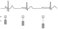
图11为采用直立的柱状图表示心房和心室收缩期的示意图;Figure 11 is a schematic diagram showing atrial and ventricular systole using an upright histogram;
图12为采用饼图表示心房和心室机械运动的示意图;Figure 12 is a schematic diagram showing mechanical motion of the atrium and ventricle using a pie chart;
图13为采用心脏图像表示心脏机械运动的示意图。FIG. 13 is a schematic diagram showing the mechanical motion of the heart using a heart image.
具体实施方式Detailed ways
本发明的构思是采用超声监护的手段来反映心脏的机械活动,采用心电监护来得到心电信号,并将心脏的机械活动与心电信号进行对比分析,以直观的方式反映心脏的电-机械活动。The concept of the present invention is to use the means of ultrasonic monitoring to reflect the mechanical activity of the heart, to obtain the ECG signal by using the ECG monitoring, and to compare and analyze the mechanical activity of the heart with the ECG signal, so as to reflect the electrical- Mechanical activity.
下面通过具体实施方式结合附图对本发明作进一步详细说明。The present invention will be further described in detail below through specific embodiments in conjunction with the accompanying drawings.
请参考图2,监护系统包括超声成像模块10、心电监护模块11、数据处理模块12和输出模块13,超声成像模块10包括探头101、图像处理单元102和发射电路103,发射电路103与探头101信号连接,图像处理单元102的输入端和探头101信号连接,数据处理模块12的输入端分别和图像处理单元102和心电监护模块11的输出端信号连接,数据处理模块12的输出端和输出模块13信号连接。信号连接可以是直接的连接,也可以通过中间元器件的处理后的连接,可以是无线通信方式的连接,也可以是有线连接。Please refer to FIG. 2 , the monitoring system includes an
探头101用于在受测机体组织表面扫描,向受测机体组织发射超声波,并接收从受测机体组织反射回来的带有组织信息的超声回波。探头10可以根据实际要求采用合适的探头。在具体实施例中,探头101通过切换开关104一方面耦合到发射电路103,在发射电路103的控制下向受测机体组织发射超声波,另一方面耦合到图像处理单元102,将接收的超声回波输出到图像处理单元102。本实施例中,探头10用于向心脏部位发射超声波,并接收从心脏组织反射回来的带有心脏组织信息的超声回波。本实施例中,探头可连续对心脏进行监测,为便于探头连续监测,探头可以是适合长时间贴合在受测机体体表的结构和/或形状。The probe 101 is used to scan the surface of the body tissue under test, transmit ultrasonic waves to the body tissue under test, and receive ultrasonic echoes with tissue information reflected from the body tissue under test. The
发射电路103用于根据需要生成发射逻辑序列,将发射逻辑序列输出到探头101,探头101将发射逻辑序列转换成超声波。本实施例中,发射电路103还控制探头在设定时间段内对受测机体组织连续扫描。另一些实施例中,为防止探头连续发射超声波导致温度上升,发射电路103也可以控制探头在每完成一个设定时间段的连续监测后间歇一段时间,扫描间隔时长和扫描周期时长可以由医生设置,例如每五分钟启动一次扫描,每次扫描进行一分钟。The transmitting
图像处理单元102用于对超声回波进行处理,例如波束合成、解调、图像处理等,最后按照要求的超声图像模式生成超声影像。本实施例中,超声影像可以为各种模式心动图。图像处理单元102可以是集成电路,也可以是分立元件组成的电路,在某些实施例中,图像处理单元102可以是处理芯片。The
心电监护模块11通常包括若干导联和处理电路,导联用于与受测机体的心脏附件的体表接触,感应心脏腔室传导的电信号。处理电路用于对电信号进行处理,例如放大、滤波、模数转换等处理,然后将处理后的心电信息输出到数据处理模块12。The
数据处理模块12用于对各种信息进行处理,也可以向监护系统的各部件发送控制信号,以对各部件进行控制,也可以用于将信息存储到存储模块14和/或从存储模块14中读取或使用信息,还可以用于将信息输出到输出模块13进行呈现,本实施例中,数据处理模块13的输入端分别和图像处理单元102和心电监护模块11的输出端信号连接,用于接收图像处理单元102输出的超声心动图和心电监护模块11输出的心电信息,根据超声心动图检测心房和心室的机械运动,并对发生机械运动的时期进行标识,得到心房和心室的机械运动标识,然后将心房和心室的机械运动标识与心电信息输出至输出模块13进行显示或呈现,以供检查人员或者医生观察。The
本发明的一些实施例中,将心房和心室的机械运动标识与心电信息输出至输出模块13进行显示或呈现可以是实时的,例如以便对监护对象进行实时监护。另一些实施例中,将心房和心室的机械运动标识与心电信息输出至输出模块13进行显示或呈现可以是非实时,例如该心房和心室的机械运动标识以及心电信息可以先存储于监护系统中,然后在需要的时候输出至输出模块13,以便医生对监护对象的情况进行后续的、离线的或者非在现场的观察和分析。In some embodiments of the present invention, outputting the mechanical motion identifiers and electrocardiographic information of the atria and ventricles to the
一些实施例中,可以将心房和心室的机械运动标识与心电信息以可对比的方式输出至输出模块13进行显示或呈现。可对比包括视觉上的对比、听觉上的对比以及两者的组合,视觉方式又可以包括图像和光信号,听觉方式包括声音,例如将心房、心室的机械运动标识与心电信息处理成可视化的图像或设定颜色的闪烁光信号,或将心房、心室的机械运动标识与心电信息处理成声音信号。由于超声心动图心电信息在采集和处理过程具有时间上的一致性,因此,可对心房、心室的机械运动标识与心电信息中的各个心电波在时间上进行对比。数据处理模块12可以是集成电路,也可以是分立元件组成的电路,在某些实施例中,数据处理模块12可以是微处理器。本实施例中,数据处理模块12与图像处理单元102可以是各自独立的模块,也可以集成为一个模块,或数据处理模块12的部分功能变换到图像处理单元102中,反之亦可。In some embodiments, the mechanical motion identifiers of the atria and ventricles and the electrocardiographic information may be output to the
输出模块13用于呈现数据处理模块12输出的信号,输出模块13可以是显示器、光发射模块或扬声器,当输出模块13是显示器时,数据处理模块12将机械运动标识处理为可视化标识,将心电信息处理为心电图,然后将心房、心室的机械运动标识与心电信息沿同一时间轴实时输出到显示器进行显示。当输出模块13是光发射模块或扬声器时,数据处理模块12将机械运动标识对应地处理为光信号或声音信号,将心电信息也对应地处理为光信号或声音信号,然后将心房、心室的机械运动标识与心电信息沿同一时间轴实时输出到光发射模块或扬声器,光发射模块根据光信号发射光,扬声器根据声音信号播放声音。可以通过光的颜色和不同的声音来区别心房、心室的机械运动和心电信息。The
基于上述监护系统对心脏周期性运动进行监测时,其一种监测方法如图3所示,包括以下步骤:When monitoring the periodic motion of the heart based on the above-mentioned monitoring system, a monitoring method thereof is shown in FIG. 3 and includes the following steps:
步骤20,接收探头收集的从受测机体的心脏反射回来的带有心脏信息的超声回波。本实施例中超声探头可以长时间贴合在病人体表,进行间歇式连续监测,即每隔一段间歇期进行一段时间的连续超声波发射和回波接收。Step 20: Receive the ultrasound echoes with cardiac information that are collected by the probe and reflected from the heart of the tested body. In this embodiment, the ultrasonic probe can be attached to the patient's body surface for a long time to perform intermittent continuous monitoring, that is, to perform continuous ultrasonic transmission and echo reception for a period of time every intermittent period.
步骤21,接收心电监护模块输出的随时间变化的心电信息。Step 21: Receive the time-varying ECG information output by the ECG monitoring module.
步骤22,基于超声回波生成超声心动图;本实施例中,超声心动图为M型超声心动图,在其他实施例中,超声心动图也可以为二维超声心动图、造影超声心动图等,在有些实施例中,超声心动图是可选的,例如超声心动图默认为某种类型的超声心动图,另外还允许用户修改超声心动图的类型,在用户选择后生成用户所选的类型。
步骤23,根据超声心动图计算实时的心动参数,心动参数包括心房舒张末时间点、心室舒张末时间点、心房收缩末时间点、心室收缩末时间点、心房舒张期时间长、心室舒张期时间长、心房收缩期时间长、心室收缩期时间长、心房舒张末内径、心室舒张末内径、心房收缩末内径和心室收缩末内径。在计算心动参数前可以先识别超声心动图的模式,根据模式将超声心动图中的特征提取出来,例如左室后壁、室间隔、左房腔壁等。根据这些特征的信息计算出心动参数。Step 23: Calculate real-time cardiac parameters according to the echocardiogram. The cardiac parameters include atrial end-diastolic time points, ventricular end-diastolic time points, atrial end-systolic time points, ventricular end-systolic time points, long atrial diastolic time, and ventricular diastolic time. Long, long atrial systolic time, long ventricular systolic time, atrial end-diastolic diameter, ventricular end-diastolic diameter, atrial end-systolic diameter and ventricular end-systolic diameter. Before calculating the cardiac parameters, the pattern of the echocardiogram can be identified, and the features of the echocardiogram, such as the posterior wall of the left ventricle, the ventricular septum, and the wall of the left atrium, can be extracted according to the pattern. Cardiac parameters are calculated from the information of these features.
以左心房的M型超声心动图(也可简称为M图)为例,一种具体的计算过程如图4所示,包括以下步骤:Taking the M-mode echocardiogram of the left atrium (also referred to as M-map for short) as an example, a specific calculation process is shown in Figure 4, including the following steps:
步骤231,对左心房的M型超声心动图进行空间平滑,以消除噪声干扰。Step 231: Perform spatial smoothing on the M-mode echocardiogram of the left atrium to eliminate noise interference.
步骤232,对平滑后的图像进行边缘提取,识别出左房腔。由于进行边缘提取后会得到主动脉腔以及左房腔的边缘位置运动轨迹,请参考图5。因此可根据主动脉腔以及左房腔的相对位置识别出左房腔,如图5所示,纵坐标在下方的空腔区域为左房腔31,上方的空腔区域为主动脉腔32。
步骤233,根据左房腔边缘位置的运动轨迹获取左房腔内径尺寸,左房腔内径尺寸即左房腔上下边缘之间的纵向距离。
步骤234,比较各时间点的左房腔内径尺寸,得到心房运动周期特征时间点,心房运动周期特征时间点包括心房舒张末时间点和心房收缩末时间点,心房舒张末时间点即心房内径最大处,见图5的标记T1\T4\T7,心房收缩末时间点即心房内径最小处,见图5的标记T2\T5\T8。
步骤235,根据心房运动周期特征时间点得到心动参数。如图5所示,根据心房运动周期特征时间点可得到心房的心动参数,图5中,T1\T4\T7时间点为心房舒张末时间点,T2\T5\T8为心房收缩末时间点,心房舒张末时间点到紧随其后的心房收缩末时间点之间的时长为心房收缩期时间长,心房收缩末时间点到紧随其后的心房舒张末时间点之间的时长为心房舒张期时间长,心房舒张末时间点处的心房内径为心房舒张末内径,心房收缩末时间点处的心房内径为心房收缩末内径。Step 235, obtaining cardiac parameters according to the characteristic time points of the atrial motion cycle. As shown in Figure 5, the cardiac parameters of the atrium can be obtained according to the characteristic time points of the atrial motion cycle. In Figure 5, the time points T1\T4\T7 are the end-diastolic time points of the atrium, and the time points T2\T5\T8 are the end-systolic time points. The length of time between the atrial end-diastolic time point and the immediately following atrial end-systolic time point is the atrial systolic time long, and the time between the atrial end-systolic time point and the immediately following atrial end-diastolic time point is the atrial diastolic time point The atrial diameter at the end-diastolic time point is the atrial end-diastolic diameter, and the atrial diameter at the atrial end-systolic time point is the atrial end-systolic diameter.
同理对左心室的M图进行空间平滑,消除噪声干扰;进行边缘提取,得到左室腔33的边缘位置运动轨迹,请见图5;获取内径尺寸,即左室腔上下边缘之间的纵向距离;得到心室运动周期特征时间点,心室运动周期特征时间点包括心室舒张末时间点和心室收缩末时间点,心室舒张末时间点即心室内径最大且开始变小的拐点处,见图5中的标记T2\T5\T8,心室收缩末时间点即心室内径最小处,见图5中的标记T3\T6\T9。同理,根据心室运动周期特征时间点也可得到心室的心动参数,图5中,T2\T5\T8时间点为心室舒张末时间点,T3\T6\T9为心室收缩末时间点,心室舒张末时间点到紧随其后的心室收缩末时间点之间的时长为心室收缩期时间长,心室收缩末时间点到紧随其后的心室舒张末时间点之间的时长为心室舒张期时间长,心室舒张末时间点处的心室内径为心室舒张末内径,心室收缩末时间点处的心室内径为心室收缩末内径。In the same way, the M image of the left ventricle is spatially smoothed to eliminate noise interference; edge extraction is performed to obtain the movement trajectory of the edge position of the left ventricular cavity 33, see Figure 5; the inner diameter is obtained, that is, the longitudinal direction between the upper and lower edges of the left ventricular cavity distance; obtain the characteristic time point of the ventricular motion cycle, the characteristic time point of the ventricular motion cycle includes the time point of the end diastole of the ventricle and the time point of the end systole of the ventricle. The mark T2\T5\T8, the end-systolic time point of the ventricle, that is, the minimum ventricular diameter, see the mark T3\T6\T9 in Figure 5. In the same way, the cardiac parameters of the ventricle can also be obtained according to the characteristic time points of the ventricular motion cycle. In Figure 5, the T2\T5\T8 time points are the ventricular end-diastolic time points, T3\T6\T9 are the ventricular end-systolic time points, and the ventricular diastolic time points are the same. The time between the end time point and the immediately following end systolic time point is the ventricular systolic time long, and the time between the end ventricular end systolic time point and the immediately following ventricular end diastolic time point is the ventricular diastolic time The ventricular inner diameter at the end-diastolic time point is the ventricular end-diastolic inner diameter, and the ventricular inner diameter at the ventricular end-systolic time point is the ventricular end-systolic inner diameter.
步骤24,根据心脏的心动参数得到实时的心房和心室的收缩期。根据心房舒张末时间点、心房收缩末时间点和心房收缩期时间长可得到心房的收缩期,根据心室舒张末时间点、心室收缩末时间点和心室收缩期时间长可得到心室的收缩期。
步骤25,生成心房和心室的收缩期对应的机械运动标识。本实施例中,心房和心室的收缩期对应的机械运动标识为可视化标识,例如,采用柱状图分别表示心房和心室的收缩期,柱状图的柱长表示该柱状图所对应腔室的收缩期时长。在呈现形式上,可以通过以下类似于“三道图”的形式进行呈现。如图5中所示,采用水平的柱状图表示心房和心室的收缩期,位于第一道的以斜线填充的柱状图34代表了心房收缩过程;位于第三道的以点状填充的柱状图35代表了心室收缩期。本实施例中,柱状图34和柱状图35的柱长方向与时间轴T平行,柱状图34柱长的两端边线分别对应心房舒张末时间点T1\T4\T7和收缩末时间点T2\T5\T8,柱长表示为心房收缩期时长。柱状图35柱长的两端边线分别对应心室舒张末时间点T2\T5\T8和收缩末时间点T3\T6\T9,柱长表示为心室收缩期时长。表示心房收缩期和心室收缩期的柱状图之间在垂直于时间轴方向上具有间距,形成位于第一道图和第三道图之间的第二道图,位于第二道图区域的连线连接两柱状图的舒张末时间点,该连线代表了顺序传导,也代表了心房与心室收缩的房室间期,连线的斜率越陡,说明从心房传到心室的时间越短,心脏跳动得越快。本实施例中的三道图方式既包括了顺序传导信息,也包括了房室收缩时间信息。
步骤26,将心房、心室的收缩期标识与心电信息以可对比的方式实时输出至输出模块。如图6-9所示,数据处理模块将心房、心室的收缩期标识与心电图沿同一时间轴实时输出到显示器进行显示。
步骤27,将心房、心室的收缩期标识和心电图联合分析。该分析过程可由医生完成,医生可通过直观的显示图像判断心电图中检测到的心房、心室电信号(分别是P波和QRS波)之后是否跟随有对应心脏腔室的机械活动,使医生的判断方式更直接、直观,避免了医生因缺乏经验而导致误判。Step 27: Jointly analyze the systolic phase markers of the atrium and the ventricle and the electrocardiogram. The analysis process can be completed by the doctor. The doctor can judge whether the atrial and ventricular electrical signals (P wave and QRS wave, respectively) detected in the ECG are followed by the mechanical activity of the corresponding heart chamber through the intuitive display image, so that the doctor can judge The method is more direct and intuitive, avoiding the misjudgment caused by the lack of experience of the doctor.
该分析过程也可由监护系统自动完成,由数据处理模块判断心电信息中的P波和QRS波和其对应腔室的收缩期标识在节律和频率上是否保持一致,即P波出现时,应同时出现心房的收缩期标识,QRS波出现时,应同时出现心室的收缩期标识。在判断两者的节律和频率不一致时输出报警信息。自动分析的方式更免去了医生判断,可直接得到判断结果并根据结果进行报警,例如当发生电-机械活动不匹配的情况时,监护仪可以给予相应报警提示。如心电图监测到某个电信号而超声心动图未检测到任何机械活动时,如图7所示,心电图虚线方框中检测到心率信号,而超声心动图中未检测到机械搏动,表明该心电信号未能引起有效的心脏搏动,即认为发生了传导阻滞;例如心电图检测到心率而超声心动图无法探测到机械活动时,如图8所示,心电图虚线方框中持续检测到心率信号,而超声心动图中显示心脏已处于停止搏动状态,即认为发生了机械停博;例如心电图检测到的心率快于超声心动图探测到的机械活动频率时,如图9所示,心电图检测到5个电信号,而超声心动图仅检测到4个机械信号,机械信号与电信号以各自的频率进行,即认为出现了频率分离。在发生心律失常或特殊情况时,也可以使用该功能更加直观的对心电诊断的结果进行确定,从而确保诊断的准确及合理性。在体外起搏的情况下,也可以使用该功能更加准确地判断心脏夺获情况,如图10所示,通过三道图进行确认每一个起搏波之后都有有效的QRS波群,因此可判断对心脏进行了夺获。The analysis process can also be completed automatically by the monitoring system. The data processing module determines whether the rhythm and frequency of the P wave and QRS wave in the ECG information are consistent with the systolic sign of the corresponding chamber. That is, when the P wave appears, it should be The systolic sign of the atrium appears at the same time, and the systolic sign of the ventricle should appear at the same time when the QRS complex appears. When it is judged that the rhythm and frequency of the two are inconsistent, an alarm message is output. The automatic analysis method also eliminates the need for doctors to judge, and can directly obtain the judgment results and alarm according to the results. For example, when the electrical-mechanical activity does not match, the monitor can give corresponding alarm prompts. If an electrical signal is detected on the ECG but no mechanical activity is detected on the echocardiography, as shown in Figure 7, the heart rate signal is detected in the dashed box on the ECG, but no mechanical pulse is detected on the echocardiography, indicating that the heart rate If the electrical signal fails to cause an effective heart beat, it is considered that conduction block has occurred; for example, when the heart rate is detected by the ECG but the mechanical activity cannot be detected by the echocardiogram, as shown in Figure 8, the heart rate signal is continuously detected in the dashed box of the ECG , and the echocardiogram shows that the heart has stopped beating, that is, mechanical arrest has occurred; for example, when the heart rate detected by the electrocardiogram is faster than the mechanical activity frequency detected by the echocardiogram, as shown in Figure 9, the electrocardiogram detected 5 electrical signals, while only 4 mechanical signals were detected by echocardiography. In the event of arrhythmia or special circumstances, this function can also be used to determine the results of ECG diagnosis more intuitively, so as to ensure the accuracy and rationality of the diagnosis. In the case of external pacing, this function can also be used to more accurately determine the cardiac capture situation. As shown in Figure 10, it is confirmed that there is an effective QRS complex after each pacing wave through three graphs. It was judged that the heart had been captured.
为更详细显示心脏腔室的内径变化,还可以在三道图附件显示心脏腔室的实时内径。For a more detailed display of the changes in the inner diameter of the heart chambers, the real-time inner diameter of the heart chambers can also be displayed in the attachment of the three-channel graph.
本实施例采用超声监护的手段来直接反映心脏的机械活动,与通过病人的体征(如无心音、脉搏、呼吸和血压等)间接反映心脏机械活动的方案相比更直接、直观和及时。并将心脏的机械活动进行标识化,以可对比的方式与心电监测获得的心电图数据进行对比分析,判断发生电-机械活动不匹配的情况,使得判断过程更加直观、减少了对医生专业技能和经验的依赖,进而使得对心脏周期性运动情况的判断更加容易和准确。This embodiment adopts the means of ultrasonic monitoring to directly reflect the mechanical activity of the heart, which is more direct, intuitive and timely than the scheme that indirectly reflects the mechanical activity of the heart through the patient's physical signs (such as absence of heart sounds, pulse, respiration, blood pressure, etc.). The mechanical activity of the heart is identified, and the electrocardiogram data obtained by ECG monitoring is compared and analyzed in a comparable way to judge the occurrence of electrical-mechanical activity mismatch, which makes the judgment process more intuitive and reduces the need for doctors' professional skills. and experience, which makes it easier and more accurate to judge the periodic motion of the heart.
本实施例中机械运动标识为心脏腔室收缩期标识,包括心房收缩期标识和心室收缩期标识,在其它的实施例中,机械运动标识也可以为心脏腔室舒张期标识,包括心房舒张期标识和心室舒张期标识。In this embodiment, the mechanical motion identifier is a cardiac chamber systolic phase identifier, including an atrial systolic phase identifier and a ventricular systolic phase identifier. In other embodiments, the mechanical motion identifier can also be a cardiac chamber diastolic phase identifier, including atrial diastolic phase identifiers. logotype and ventricular diastole logotype.
在其它实施例中,也可以采用的展现方式直观地表现心房和心室的机械运动以及二者之间的传导信息。例如图11所示,采用直立的柱状图表示心房和心室的收缩期,两柱状图显示在同列,柱长方向与时间轴垂直,柱状图的柱长表示为柱状图所对应腔室的收缩期时长,图中,柱状图A表示心房收缩期标识,柱状图V表示心室收缩期标识,两柱状图在与时间轴垂直方向上的间距A-V与房室传导的时间关联,间距越大反映房室传导越慢,间距越大反映房室传导越快。又例如图12所示,采用饼图表示心房和心室的机械运动,饼图随着时间的推移,围绕圆心刷新。每刷新一周,代表一个心动周期;依次刷新出心房收缩信息、房室间期信息、心室收缩信息;图中,扇形A表示心房收缩期标识,扇形V表示心室收缩期标识,扇形角度的大小代表了时间的长短,A-V表示房室传导。再例如图13所示,采用心脏收缩示意图表示心房和心室的机械运动,可根据超声心动图所获得的心脏径线信息,还原心脏收缩、舒张的图示,这种呈现方式可更加直观的将心脏的机械运动展现给用户。In other embodiments, the mechanical motion of the atrium and the ventricle and the conduction information between them can also be visually represented in a presentation manner. For example, as shown in Figure 11, a vertical bar graph is used to represent the systolic period of the atrium and ventricle. The two histograms are displayed in the same column, and the direction of the column length is perpendicular to the time axis. Duration, in the figure, histogram A represents the sign of atrial systole, histogram V represents the sign of ventricular systole, the distance A-V between the two histograms in the direction perpendicular to the time axis is related to the time of atrioventricular conduction, and the larger the distance, the more atrioventricular The slower the conduction, the larger the spacing reflects the faster atrioventricular conduction. For another example, as shown in Fig. 12, a pie chart is used to represent the mechanical motion of the atrium and ventricle, and the pie chart is refreshed around the center of the circle over time. Each refresh week represents a cardiac cycle; atrial systolic information, atrioventricular interval information, and ventricular systolic information are refreshed in turn; in the figure, sector A represents the sign of atrial systole, sector V represents the sign of ventricular systole, and the size of the sector angle represents Depending on the length of time, A-V indicates atrioventricular conduction. For another example, as shown in Figure 13, the mechanical motion of the atrium and ventricle is represented by the schematic diagram of cardiac systole, and the diagrams of cardiac systole and diastole can be restored according to the cardiac diameter information obtained by echocardiography. The mechanical movement of the heart is displayed to the user.
此外,还可以通过超声感受到的声音信息,来反映房室收缩、舒张,及其间期有关的信息,例如采用“嘟”反映心脏机械运动的声音,采用“哔”反映心脏的心电信号。使用声音的方式进行展示,使得医护人员可以通过声音,更加直观的辨别患者心脏功能的变化情况。另外,也可将两者中的一者采用声音,另一采用图像显示。In addition, the information about atrioventricular contraction, diastole, and its interval can also be reflected through the sound information felt by ultrasound, for example, "beep" is used to reflect the mechanical movement of the heart, and "beep" is used to reflect the heart's ECG signal. The use of sound to display, so that medical staff can more intuitively identify the changes in the patient's heart function through the sound. In addition, one of the two may be displayed as a sound, and the other as an image display.
本领域技术人员可以理解,上述实施方式中各种方法的全部或部分步骤可以通过程序来指令相关硬件完成,该程序可以存储于一计算机可读存储介质中,存储介质可以包括:只读存储器、随机存储器、磁盘或光盘等。Those skilled in the art can understand that all or part of the steps of the various methods in the above-mentioned embodiments can be completed by instructing relevant hardware through a program, and the program can be stored in a computer-readable storage medium, and the storage medium can include: read-only memory, Random access memory, magnetic disk or CD, etc.
以上应用了具体个例对本发明进行阐述,只是用于帮助理解本发明而并不用以限制本发明。对于本领域的一般技术人员,依据本发明的思想,可以对上述具体实施方式进行变化。The present invention is described above using specific examples, which are only used to help understand the present invention and are not intended to limit the present invention. For those skilled in the art, according to the idea of the present invention, the above-mentioned specific embodiments can be changed.
Claims (17)
Translated fromChinesePriority Applications (1)
| Application Number | Priority Date | Filing Date | Title |
|---|---|---|---|
| CN202010955265.2ACN112043259B (en) | 2015-07-10 | 2015-07-10 | Monitoring system, method and device |
Applications Claiming Priority (1)
| Application Number | Priority Date | Filing Date | Title |
|---|---|---|---|
| PCT/CN2015/083766WO2017008202A1 (en) | 2015-07-10 | 2015-07-10 | Monitoring system, method and device |
Related Child Applications (1)
| Application Number | Title | Priority Date | Filing Date |
|---|---|---|---|
| CN202010955265.2ADivisionCN112043259B (en) | 2015-07-10 | 2015-07-10 | Monitoring system, method and device |
Publications (2)
| Publication Number | Publication Date |
|---|---|
| CN107708570A CN107708570A (en) | 2018-02-16 |
| CN107708570Btrue CN107708570B (en) | 2020-10-16 |
Family
ID=57756663
Family Applications (2)
| Application Number | Title | Priority Date | Filing Date |
|---|---|---|---|
| CN202010955265.2AActiveCN112043259B (en) | 2015-07-10 | 2015-07-10 | Monitoring system, method and device |
| CN201580081329.8AActiveCN107708570B (en) | 2015-07-10 | 2015-07-10 | Monitoring system, method and device |
Family Applications Before (1)
| Application Number | Title | Priority Date | Filing Date |
|---|---|---|---|
| CN202010955265.2AActiveCN112043259B (en) | 2015-07-10 | 2015-07-10 | Monitoring system, method and device |
Country Status (3)
| Country | Link |
|---|---|
| US (1) | US10918358B2 (en) |
| CN (2) | CN112043259B (en) |
| WO (1) | WO2017008202A1 (en) |
Families Citing this family (4)
| Publication number | Priority date | Publication date | Assignee | Title |
|---|---|---|---|---|
| CN108324265A (en)* | 2018-02-26 | 2018-07-27 | 河南善仁医疗科技有限公司 | The method for analyzing electrocardiogram caardiophonogram based on heart sound feature location |
| CN112584738B (en)* | 2018-08-30 | 2024-04-23 | 奥林巴斯株式会社 | Recording device, image observation device, observation system, control method of observation system, and storage medium |
| EP4124296A1 (en) | 2021-07-30 | 2023-02-01 | Koninklijke Philips N.V. | A system and method for assessment of electromechanical remodeling during cardiac fibrillation |
| CN114424944B (en)* | 2021-12-31 | 2024-05-03 | 纳龙健康科技股份有限公司 | Method for quickly identifying atrioventricular block, terminal equipment and storage medium |
Citations (6)
| Publication number | Priority date | Publication date | Assignee | Title |
|---|---|---|---|---|
| US20010031919A1 (en)* | 1999-05-18 | 2001-10-18 | Mediguide Ltd | Medical imaging and navigation system |
| US20030163045A1 (en)* | 2002-02-28 | 2003-08-28 | Koninklijke Philips Electronics N.V. | Ultrasound imaging enhancement to clinical patient monitoring functions |
| CN1486675A (en)* | 2002-06-18 | 2004-04-07 | ��ʽ���綫֥ | Ultrasound diagnostic device for adjusting temporal phase between multiple image series |
| CN1586404A (en)* | 2004-07-09 | 2005-03-02 | 清华大学 | Method for detecting myocardial blood supply state based on myocardial edge tracking |
| EP1806594A3 (en)* | 2006-01-06 | 2007-12-12 | Medison Co., Ltd. | Ultrasound system and method of displaying ultrasound image |
| CN101527047A (en)* | 2008-03-05 | 2009-09-09 | 深圳迈瑞生物医疗电子股份有限公司 | Method and device for detecting tissue boundaries by use of ultrasonic images |
Family Cites Families (19)
| Publication number | Priority date | Publication date | Assignee | Title |
|---|---|---|---|---|
| JPH03191951A (en)* | 1989-12-21 | 1991-08-21 | Toshiba Corp | Ultrasound diagnostic equipment |
| US6673018B2 (en)* | 2001-08-31 | 2004-01-06 | Ge Medical Systems Global Technology Company Llc | Ultrasonic monitoring system and method |
| US7037266B2 (en)* | 2002-04-25 | 2006-05-02 | Medtronic, Inc. | Ultrasound methods and implantable medical devices using same |
| US20070167809A1 (en)* | 2002-07-22 | 2007-07-19 | Ep Medsystems, Inc. | Method and System For Estimating Cardiac Ejection Volume And Placing Pacemaker Electrodes Using Speckle Tracking |
| US20040215077A1 (en)* | 2002-11-08 | 2004-10-28 | Witt Jerome F. | Color ensemble interleave with artifact elimination in time-gated anatomical imaging |
| JP2005342006A (en)* | 2004-05-31 | 2005-12-15 | Toshiba Corp | Ultrasonic diagnostic apparatus, ultrasonic image processing apparatus, and ultrasonic signal processing program |
| JP2008511346A (en)* | 2004-08-30 | 2008-04-17 | アスコム・リミテッド | A method and apparatus for defining a cardiac time interval. |
| WO2006123729A1 (en)* | 2005-05-19 | 2006-11-23 | Hitachi Medical Corporation | Ultrasonographic device and image processing method thereof |
| JP4805669B2 (en)* | 2005-12-27 | 2011-11-02 | 株式会社東芝 | Ultrasonic image processing apparatus and control program for ultrasonic image processing apparatus |
| JP4912807B2 (en) | 2006-09-22 | 2012-04-11 | 株式会社東芝 | Ultrasound diagnostic imaging equipment |
| US20100049052A1 (en)* | 2006-10-26 | 2010-02-25 | Cardiogal Ltd. | Non-invasive cardiac parameter measurement |
| EP1930045A1 (en)* | 2006-12-08 | 2008-06-11 | BIOTRONIK CRM Patent AG | Implantable medical system with acoustic sensor to measure mitral blood flow |
| US20080146940A1 (en)* | 2006-12-14 | 2008-06-19 | Ep Medsystems, Inc. | External and Internal Ultrasound Imaging System |
| US8167807B2 (en)* | 2007-12-20 | 2012-05-01 | Toshiba Medical Systems Corporation | Ultrasonic diagnosis device, ultrasonic image analysis device, and ultrasonic image analysis method |
| WO2011121493A1 (en)* | 2010-04-01 | 2011-10-06 | Koninklijke Philips Electronics N.V. | Bullseye display for ecg data |
| JP5597492B2 (en)* | 2010-09-08 | 2014-10-01 | 株式会社東芝 | Ultrasonic diagnostic apparatus, image processing apparatus, and program |
| JP6041350B2 (en)* | 2012-03-30 | 2016-12-07 | 東芝メディカルシステムズ株式会社 | Ultrasonic diagnostic apparatus, image processing apparatus, and image processing method |
| US20150018632A1 (en)* | 2012-09-14 | 2015-01-15 | Mohammad Khair | System and Method For Monitoring Cardiac Blood Flow Balance Between The Right and Left Heart Chambers |
| US9492138B2 (en)* | 2012-10-15 | 2016-11-15 | Rijuven Corp | Mobile front-end system for comprehensive cardiac diagnosis |
- 2015
- 2015-07-10CNCN202010955265.2Apatent/CN112043259B/enactiveActive
- 2015-07-10WOPCT/CN2015/083766patent/WO2017008202A1/ennot_activeCeased
- 2015-07-10CNCN201580081329.8Apatent/CN107708570B/enactiveActive
- 2018
- 2018-01-05USUS15/863,363patent/US10918358B2/enactiveActive
Patent Citations (6)
| Publication number | Priority date | Publication date | Assignee | Title |
|---|---|---|---|---|
| US20010031919A1 (en)* | 1999-05-18 | 2001-10-18 | Mediguide Ltd | Medical imaging and navigation system |
| US20030163045A1 (en)* | 2002-02-28 | 2003-08-28 | Koninklijke Philips Electronics N.V. | Ultrasound imaging enhancement to clinical patient monitoring functions |
| CN1486675A (en)* | 2002-06-18 | 2004-04-07 | ��ʽ���綫֥ | Ultrasound diagnostic device for adjusting temporal phase between multiple image series |
| CN1586404A (en)* | 2004-07-09 | 2005-03-02 | 清华大学 | Method for detecting myocardial blood supply state based on myocardial edge tracking |
| EP1806594A3 (en)* | 2006-01-06 | 2007-12-12 | Medison Co., Ltd. | Ultrasound system and method of displaying ultrasound image |
| CN101527047A (en)* | 2008-03-05 | 2009-09-09 | 深圳迈瑞生物医疗电子股份有限公司 | Method and device for detecting tissue boundaries by use of ultrasonic images |
Also Published As
| Publication number | Publication date |
|---|---|
| CN107708570A (en) | 2018-02-16 |
| WO2017008202A1 (en) | 2017-01-19 |
| US10918358B2 (en) | 2021-02-16 |
| CN112043259B (en) | 2025-01-10 |
| CN112043259A (en) | 2020-12-08 |
| US20190125311A1 (en) | 2019-05-02 |
Similar Documents
| Publication | Publication Date | Title |
|---|---|---|
| JP5877816B2 (en) | Ultrasonic image capturing apparatus and ultrasonic image capturing method | |
| US8057394B2 (en) | Ultrasound image processing to render three-dimensional images from two-dimensional images | |
| US8777856B2 (en) | Diagnostic system and method for obtaining an ultrasound image frame | |
| JP5906234B2 (en) | Visualization of myocardial infarct size in diagnostic ECG | |
| US9855024B2 (en) | Medical diagnostic imaging apparatus, medical image processing apparatus, and control method for processing motion information | |
| US9179889B2 (en) | Ultrasonic diagnostic device, and method for measuring initma-media complex thickness | |
| CN105580049B (en) | Ultrasound monitoring equipment and method | |
| JP2006068524A (en) | Extraction of abbreviated ultrasonic information useful for inexperienced user of ultrasound | |
| US10918357B2 (en) | Methods and systems for automatically determining an anatomical measurement of ultrasound images | |
| CN107708570B (en) | Monitoring system, method and device | |
| US20180303345A1 (en) | System and Method for Imaging Episodic Cardiac Conditions | |
| JP2018507015A (en) | Wearable Doppler ultrasound-based cardiac monitoring | |
| US20210030402A1 (en) | Method and system for providing real-time end of ultrasound examination analysis and reporting | |
| CN114762611B (en) | Processing methods of multiple dynamic parameters of the body and their application in ejection fraction | |
| US11304681B2 (en) | Ultrasonic diagnostic apparatus and image processing method | |
| JP4300460B2 (en) | Ultrasonic diagnostic equipment | |
| JP2012016508A (en) | Ultrasonic diagnostic apparatus and signal analysis program | |
| US12361548B2 (en) | Method and system for providing an objective image quality metric after ultrasound image acquisition and prior to permanent storage | |
| US20250241710A1 (en) | Automated tool for identifying and correcting tenting artifacts in anatomical mapping | |
| JP7277345B2 (en) | Image processing device and image processing program | |
| JP2025020050A (en) | Method and system for shaving anatomical maps - Patents.com |
Legal Events
| Date | Code | Title | Description |
|---|---|---|---|
| PB01 | Publication | ||
| PB01 | Publication | ||
| SE01 | Entry into force of request for substantive examination | ||
| SE01 | Entry into force of request for substantive examination | ||
| GR01 | Patent grant | ||
| GR01 | Patent grant |