Movatterモバイル変換


[0]ホーム

URL:


CN107706657B - Connector assembly - Google Patents

Connector assembly
Download PDF

Info

Publication number
CN107706657B
CN107706657BCN201710665547.7ACN201710665547ACN107706657BCN 107706657 BCN107706657 BCN 107706657BCN 201710665547 ACN201710665547 ACN 201710665547ACN 107706657 BCN107706657 BCN 107706657B
Authority
CN
China
Prior art keywords
cage
pluggable module
gasket
pluggable
wall
Prior art date
Legal status (The legal status is an assumption and is not a legal conclusion. Google has not performed a legal analysis and makes no representation as to the accuracy of the status listed.)
Active
Application number
CN201710665547.7A
Other languages
Chinese (zh)
Other versions
CN107706657A (en
Inventor
M.J.菲利普斯
R.R.亨利
Current Assignee (The listed assignees may be inaccurate. Google has not performed a legal analysis and makes no representation or warranty as to the accuracy of the list.)
Tailian Solutions Co ltd
Original Assignee
TE Connectivity Corp
Priority date (The priority date is an assumption and is not a legal conclusion. Google has not performed a legal analysis and makes no representation as to the accuracy of the date listed.)
Filing date
Publication date
Application filed by TE Connectivity CorpfiledCriticalTE Connectivity Corp
Publication of CN107706657ApublicationCriticalpatent/CN107706657A/en
Application grantedgrantedCritical
Publication of CN107706657BpublicationCriticalpatent/CN107706657B/en
Activelegal-statusCriticalCurrent
Anticipated expirationlegal-statusCritical

Links

Images

Classifications

Landscapes

Abstract

Translated fromChinese

一种连接器组件(104),包括用于可插拔模块(106)的EMI抑制的笼构件(108),该笼构件具有限定腔室(119)的笼套管(114)、联接到所述笼套管的基部(116)、以及接收在腔室中的笼衬垫(118)。笼衬垫限定配置为接收可插拔模块(106)的模块腔体(120)。笼套管在前端(110)和后端(112)之间延伸,并且包括限定所述腔室的多个笼壁(150),所述笼壁在所述后端处或在所述后端附近围绕通信连接器(122)。笼衬垫电连接至笼套管并且围绕可从模块的配合周边(144)。笼衬垫在腔室内延伸可插拔模块的大部分长度,以为可插拔模块提供EMI屏蔽。笼衬垫在可插拔模块和笼套管之间提供电路径。

Figure 201710665547

A connector assembly (104) includes a cage member (108) for EMI suppression of a pluggable module (106), the cage member having a cage sleeve (114) defining a cavity (119), coupled to the The base (116) of the cage sleeve, and the cage liner (118) received in the chamber. The cage gasket defines a module cavity (120) configured to receive the pluggable module (106). A cage sleeve extends between a front end (110) and a rear end (112) and includes a plurality of cage walls (150) defining the chamber, the cage walls at or at the rear end The communication connector (122) is surrounded nearby. The cage gasket is electrically connected to the cage sleeve and surrounds the mating perimeter (144) of the slave module. The cage gasket extends most of the length of the pluggable module within the chamber to provide EMI shielding for the pluggable module. The cage gasket provides an electrical path between the pluggable module and the cage bushing.

Figure 201710665547

Description

Translated fromChinese
连接器组件connector assembly

技术领域technical field

文中描述的主题涉及用于可插拔模块的EMI屏蔽。The subject matter described herein relates to EMI shielding for pluggable modules.

背景技术Background technique

至少一些已知的通信系统包括插座组件,诸如输入/输出(I/O)连接器组件,其被配置为接收可插拔模块、并且在可插拔模块与插座组件的电连接器之间建立通信连接。作为一个示例,已知的插座组件包括笼构件,该笼构件被安装至电路板,并且被配置为接收小型(form-factor,SFP)可插拔收发器。插座组件包括细长形的腔体,该腔体在腔体的开口与布置在该腔体内且安装至电路板的电连接器之间延伸。可插拔模块穿过开口被插入、并且在腔体中朝着电连接器前进。可插拔模块和电连接器具有相应的电触头,所述相应的电触头彼此接合以建立通信连接。At least some known communication systems include a receptacle assembly, such as an input/output (I/O) connector assembly, configured to receive a pluggable module and establish between the pluggable module and an electrical connector of the receptacle assembly communication connection. As one example, a known receptacle assembly includes a cage member that is mounted to a circuit board and that is configured to receive a form-factor (SFP) pluggable transceiver. The socket assembly includes an elongated cavity extending between an opening of the cavity and an electrical connector disposed within the cavity and mounted to a circuit board. The pluggable module is inserted through the opening and advances in the cavity towards the electrical connector. The pluggable module and the electrical connector have corresponding electrical contacts that engage with each other to establish a communication connection.

在可插拔模块和插座组件的设计中,经常遇到的一个挑战是电磁干扰(EMI)的抑制和管理,该电磁干扰不利地影响模块/系统电性能。例如,冲压形成的部件典型地具有通过冲压和成型过程形成在其中的开口或槽,所述开口或槽操作为EMI泄漏位置、以及在部件的接口处的以及沿着部件的接缝。典型的,EMI垫片设置在开口处,以抑制系统中的EMI泄漏和/或阻挡EMI辐射进入系统。笼构件从而由多个零件制造而成,导致制造困难和昂贵成本以及组装困难。此外,笼构件典型地在到模块腔体的端口开口处包括EMI垫片,其使用金属梁或金属指阻挡开口中的围绕可插拔模块的几乎所有空间。然而,这样的EMI垫片具有阻挡气流通过开口的不利影响,而该气流可被用于冷却可插拔模块或系统的其他部件。一些已知的通信系统被设计为在开口处设置较大的气流通道,以促进气流流入或流出笼构件。EMI垫片必须被移除以设置气流通道。One challenge often encountered in the design of pluggable modules and socket assemblies is the suppression and management of electromagnetic interference (EMI) that adversely affects module/system electrical performance. For example, stamped-formed components typically have openings or slots formed therein by a stamping and forming process that operate as EMI leakage locations, as well as seams at the interfaces of the components and along the components. Typically, EMI gaskets are provided at the openings to suppress EMI leakage in the system and/or block EMI radiation from entering the system. The cage member is thus manufactured from multiple parts, resulting in difficult and expensive manufacturing and assembly difficulties. Additionally, cage members typically include EMI gaskets at port openings to the module cavity, which use metal beams or metal fingers to block nearly all of the space in the opening around the pluggable module. However, such EMI gaskets have the detrimental effect of blocking airflow through the openings that could be used to cool pluggable modules or other components of the system. Some known communication systems are designed with larger airflow channels at the openings to facilitate airflow into or out of the cage members. EMI gaskets must be removed to provide airflow channels.

因此,需要一种可插拔模块的EMI屏蔽,其用于通信系统中,该EMI屏蔽包括有限数量的部件、附接点和接缝,以改善笼构件的EMI抑制。Accordingly, there is a need for an EMI shield for pluggable modules for use in communication systems that includes a limited number of components, attachment points and seams to improve EMI suppression of cage members.

发明内容SUMMARY OF THE INVENTION

根据本发明,提供了一种连接器组件,其包括用于可插拔模块的EMI抑制的笼构件。该笼构件具有限定腔室的笼套管,联接到笼套管并且沿着笼构件的底部延伸的基部,以及接收在腔室中的笼衬垫。笼衬垫限定配置为接收可插拔模块的模块腔体。笼套管在前端和后端之间延伸,并且包括限定腔室的多个笼壁。笼壁配置为在后端处或在后端附近围绕通信连接器。笼衬垫电连接至笼套管,并且配置为在可插拔模块的配合端的前方围绕可插拔模块的配合周边,该配合端配置为与通信连接器配合。笼衬垫在腔室内延伸可插拔模块的大部分长度,以为可插拔模块提供EMI屏蔽。笼衬垫在可插拔模块和笼套管之间提供电路径。In accordance with the present invention, a connector assembly is provided that includes a cage member for EMI suppression of pluggable modules. The cage member has a cage sleeve defining a cavity, a base coupled to the cage sleeve and extending along a bottom of the cage member, and a cage liner received in the cavity. The cage gasket defines a module cavity configured to receive the pluggable module. A cage sleeve extends between the front and rear ends and includes a plurality of cage walls that define a cavity. The cage wall is configured to surround the communication connector at or near the back end. The cage gasket is electrically connected to the cage sleeve and is configured to surround the mating perimeter of the pluggable module in front of the mating end of the pluggable module, the mating end being configured to mate with the communication connector. The cage gasket extends most of the length of the pluggable module within the chamber to provide EMI shielding for the pluggable module. The cage gasket provides an electrical path between the pluggable module and the cage bushing.

附图说明Description of drawings

图1是根据一种实施例的通信系统的前部透视图,其示出了单端口插座组件;1 is a front perspective view of a communication system showing a single port jack assembly according to one embodiment;

图2是根据一种实施例的通信系统的前部透视图,其示出了多端口插座组件;2 is a front perspective view of a communication system showing a multi-port jack assembly, according to one embodiment;

图3是通信系统的可插拔模块的前部透视图;3 is a front perspective view of a pluggable module of the communication system;

图4是图1中示出的插座组件的分解图,该插座组件具有根据示例性实施例的笼构件;4 is an exploded view of the socket assembly shown in FIG. 1 having a cage member according to an exemplary embodiment;

图5是根据示例性实施例的笼构件的笼套管的顶部透视图;5 is a top perspective view of a cage sleeve of a cage member according to an exemplary embodiment;

图6是根据示例性实施例的笼套管的底部透视图;6 is a bottom perspective view of a cage sleeve according to an exemplary embodiment;

图7是根据示例性实施例的笼构件的笼衬垫的后部透视图;7 is a rear perspective view of a cage liner of a cage member according to an exemplary embodiment;

图8是笼衬垫的底部透视图;Figure 8 is a bottom perspective view of the cage liner;

图9是根据示例性实施例的笼构件的基部的后部透视图;9 is a rear perspective view of a base of a cage member according to an exemplary embodiment;

图10是处于组装状态的插座组件的前部透视图;Figure 10 is a front perspective view of the socket assembly in an assembled state;

图11是处于组装状态的插座组件的底部透视图,其示出了笼构件中的可插拔模块和通信连接器;11 is a bottom perspective view of the receptacle assembly in an assembled state showing the pluggable modules and communication connectors in the cage member;

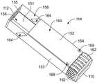
图12是笼衬垫的后端的顶部透视图,其示出了接收在笼衬垫中的可插拔模块;Figure 12 is a top perspective view of the rear end of the cage liner showing a pluggable module received in the cage liner;

图13是笼衬垫的后端的底部透视图,其示出了接收在笼衬垫中的可插拔模块。13 is a bottom perspective view of the rear end of the cage liner showing the pluggable modules received in the cage liner.

具体实施方式Detailed ways

文中描述的实施例包括用于通信系统的电磁干扰(EMI)屏蔽,诸如在笼构件和可插拔模块之间的电磁干扰屏蔽。笼构件包括包封可插拔模块以提供EMI屏蔽的多个零件。笼构件在通信系统的通信连接器和可插拔模块之间的配合接口处提供EMI屏蔽。Embodiments described herein include electromagnetic interference (EMI) shielding for communication systems, such as electromagnetic interference shielding between cage members and pluggable modules. The cage member includes various parts that encapsulate the pluggable module to provide EMI shielding. The cage member provides EMI shielding at the mating interface between the communication connector and the pluggable module of the communication system.

图1是根据一种实施例的通信系统100的前部透视图,其示出了单端口插座组件。图2是根据一种实施例的通信系统100的前部透视图,其示出了多端口插座组件。通信系统100包括电路板102,安装到电路板102的插座组件104,以及被配置为通信地接合插座组件104的一个或多个可插拔模块106。单端口插座组件104(图1)配置为接收单个可插拔模块106,而多端口插座组件104(图2)配置为接收多个可插拔模块106。图2示出了插座组件104的并排成组的多个端口;然而,插座组件104可包括除了所述成组的端口之外的或者替代所述成组的端口的堆叠的多个端口。1 is a front perspective view of acommunication system 100 showing a single port jack assembly, according to one embodiment. FIG. 2 is a front perspective view of thecommunication system 100 showing a multi-port jack assembly, according to one embodiment. Thecommunication system 100 includes acircuit board 102 , areceptacle assembly 104 mounted to thecircuit board 102 , and one ormore pluggable modules 106 configured to communicatively engage thereceptacle assembly 104 . The single-port receptacle assembly 104 ( FIG. 1 ) is configured to receive asingle pluggable module 106 , while the multi-port receptacle assembly 104 ( FIG. 2 ) is configured to receivemultiple pluggable modules 106 . FIG. 2 shows the multiple ports of thereceptacle assembly 104 in a side-by-side group; however, thereceptacle assembly 104 may include stacked multiple ports in addition to or instead of the grouped ports.

可插拔模块106是被配置为插入到插座组件104中并且从插座组件104移除的输入/输出(I/O)模块。在一些实施例中,可插拔模块106是小型可插拔(SFP)收发器、或四芯组(quad)小型可插拔(QSFP)收发器。可插拔模块106可满足SFP或QSFP收发器的某些技术规格,诸如小型(Small-Form Factor,SFF)-8431。在一些实施例中,可插拔模块106被配置为传输高达2.5千兆位每秒(Gbps)、高达5.0Gbps、高达10.0Gbps或更高的数据信号。通过示例的方式,插座组件104和可插拔模块106可分别类似于插座笼和收发器,它们是可购于TEConnectivity的SFP+产品系列的部分。Pluggable modules 106 are input/output (I/O) modules that are configured to be inserted into and removed fromreceptacle assembly 104 . In some embodiments, thepluggable module 106 is a small form factor pluggable (SFP) transceiver, or a quad small form factor pluggable (QSFP) transceiver. Thepluggable module 106 may meet certain specifications for SFP or QSFP transceivers, such as Small-Form Factor (SFF)-8431. In some embodiments, thepluggable modules 106 are configured to transmit data signals up to 2.5 gigabits per second (Gbps), up to 5.0 Gbps, up to 10.0 Gbps, or higher. By way of example,receptacle assembly 104 andpluggable module 106 may be similar to receptacle cages and transceivers, respectively, which are part of the SFP+ product line available from TE Connectivity.

通信系统100可以是远程通信系统或装置的一部分或与其一同使用。例如,通信系统100可以是交换机、路由器、服务器、集线器、网络接口卡、或存储系统中的一部分,或者包括交换机、路由器、服务器、集线器、网络接口卡、或存储系统。在各种实施例中,可插拔模块106被配置为传送呈电信号的形式的数据信号。在其他实施例中,可插拔模块106可被配置为传送呈光信号的形式的数据信号。电路板102可以是子卡或母板,并且包括延伸穿过它的导电迹线(未示出)。Communication system 100 may be part of or used with a telecommunication system or apparatus. For example,communication system 100 may be part of, or include a switch, router, server, hub, network interface card, or storage system, or include a switch, router, server, hub, network interface card, or storage system. In various embodiments, thepluggable modules 106 are configured to transmit data signals in the form of electrical signals. In other embodiments, thepluggable module 106 may be configured to transmit data signals in the form of optical signals.Circuit board 102 may be a daughter card or a motherboard, and includes conductive traces (not shown) extending therethrough.

插座组件104包括被安装至电路板102的笼构件108。笼构件108可被布置在系统或装置的机架的挡板或面板109处,诸如穿过面板109中的开口。如此,笼构件108处于装置和对应的面板109的内部,并且(一个或多个)可插拔模块106从装置和对应的面板109的外侧或外部被装载到笼构件108中。Thesocket assembly 104 includes acage member 108 that is mounted to thecircuit board 102 . Thecage member 108 may be disposed at a baffle orpanel 109 of a rack of a system or device, such as through an opening in thepanel 109 . As such, thecage member 108 is internal to the device andcorresponding panel 109 and the pluggable module(s) 106 are loaded into thecage member 108 from the outside or outside of the device andcorresponding panel 109 .

笼构件108包括前端110和相反的后端112。前端110可被设置在面板109中的开口处、并且延伸穿过所述开口。诸如“前”、“后”、“顶”、或“底”等相对性或空间术语仅被用于区分附图标记所标出的元件,并且不一定要求在通信系统100中、或在通信系统100的周围环境中的特定位置或取向。例如,前端110可位于更大的远程通信系统的后部部分处,或者面向该后部部分。在许多应用中,当用户将可插拔模块106插入到插座组件104中时,前端110对于用户是可见的。Thecage member 108 includes afront end 110 and an oppositerear end 112 .Front end 110 may be positioned at and extend through an opening inpanel 109 . Relative or spatial terms such as "front," "rear," "top," or "bottom" are used only to distinguish the elements identified by the reference numbers, and are not necessarily required in thecommunication system 100, or in communication A particular location or orientation in the surrounding environment of thesystem 100 . For example, thefront end 110 may be located at or facing the rear portion of a larger telecommunications system. In many applications, thefront end 110 is visible to the user when the user inserts thepluggable module 106 into thereceptacle assembly 104 .

在配合操作过程中,笼构件108被配置为抑制或阻挡电磁干扰(EMI)以及引导(一个或多个)可插拔模块106。为此,笼构件108包括组装在一起的多个零件以包封可插拔模块106。例如,该多个零件可被卡合在一起和/或焊接在一起。当笼构件108被安装至电路板102时,笼构件108被电联接至电路板102,并且特别地,被电联接至电路板102内的接地平面(未示出),以将笼构件108电接地。如此,插座组件104可减少可能不利地影响通信系统100的电性能的EMI。Thecage member 108 is configured to suppress or block electromagnetic interference (EMI) and to guide the pluggable module(s) 106 during mating operation. To this end, thecage member 108 includes multiple pieces assembled together to enclose thepluggable module 106 . For example, the multiple pieces may be snapped together and/or welded together. When thecage member 108 is mounted to thecircuit board 102 , thecage member 108 is electrically coupled to thecircuit board 102 and, in particular, to a ground plane (not shown) within thecircuit board 102 to electrically connect thecage member 108 to thecircuit board 102 . ground. In this manner, thereceptacle assembly 104 may reduce EMI that may adversely affect the electrical performance of thecommunication system 100 .

在示例性实施例中,笼构件108包括笼套管114,联接到笼套管114的基部116,以及联接到笼套管114和/或基部116的一个或多个笼衬垫118(在图4中示出)。笼套管114、基部116和笼衬垫118每个包括互连以形成笼构件108的壁或面板。在一个示例性实施例中,笼套管114限定前端110和后端112。可选地,对于多端口插座组件104(图2),笼套管114接收多个笼衬垫118以限定多个端口。笼套管114围绕所有的端口,并且基部116在所有的端口下方延伸。对于单端口插座组件104(图1),仅一个笼衬垫118被接收在笼套管114中。In the exemplary embodiment,cage member 108 includescage sleeve 114 ,base 116 coupled tocage sleeve 114 , and one ormore cage liners 118 coupled tocage sleeve 114 and/or base 116 (in FIG. 4).Cage sleeve 114 ,base 116 , andcage liner 118 each include walls or panels that interconnect to formcage member 108 . In one exemplary embodiment, thecage sleeve 114 defines aforward end 110 and arearward end 112 . Optionally, for the multi-port receptacle assembly 104 (FIG. 2), thecage sleeve 114 receives a plurality ofcage liners 118 to define a plurality of ports.Cage sleeves 114 surround all ports, and bases 116 extend below all ports. For the single port receptacle assembly 104 ( FIG. 1 ), only onecage gasket 118 is received in thecage sleeve 114 .

笼构件108的零件由导电材料形成,诸如金属片材和/或具有导电颗粒的聚合物。在图示的实施例中,零件由金属片材冲压和成型。在一些实施例中,笼构件108被配置为有助于气流通过笼构件108,以将热量(或热能)从插座组件104和(一个或多个)可插拔模块106传送离开。空气可从笼构件108的内部(例如,面板109的后方)流动至外部环境(例如,面板109的前方),或者从笼构件108的外侧流动至笼构件108的内部中。风扇或其他空气移动装置可被用于增大穿过笼构件108、以及越过(一个或多个)可插拔模块106的气流。The parts of thecage member 108 are formed from conductive materials, such as metal sheets and/or polymers with conductive particles. In the illustrated embodiment, the parts are stamped and formed from sheet metal. In some embodiments,cage member 108 is configured to facilitate airflow throughcage member 108 to transfer heat (or thermal energy) away fromsocket assembly 104 and pluggable module(s) 106 . Air may flow from the interior of the cage member 108 (eg, behind the panel 109 ) to the outside environment (eg, in front of the panel 109 ), or from the outside of thecage member 108 into the interior of thecage member 108 . A fan or other air moving device may be used to increase airflow through thecage member 108 and across the pluggable module(s) 106 .

笼套管114限定在前端110和后端112之间延伸的腔室119。(一个或多个)笼衬垫118被接收在腔室119中。笼衬垫118限定接收可插拔模块106的模块腔体120。模块腔体120在平行于配合轴线的方向上纵向地延伸。对于多端口插座组件104(图2),多个笼衬垫118被接收在腔室119中,从而限定了用于接收多个可插拔模块的多个模块腔体120或端口。模块腔体120可竖直地堆叠和/或水平地堆叠。Cage sleeve 114 defines acavity 119 extending betweenfront end 110 andrear end 112 . Cage liner(s) 118 are received incavity 119 . Thecage gasket 118 defines amodule cavity 120 that receives thepluggable module 106 . Themodule cavity 120 extends longitudinally in a direction parallel to the mating axis. For the multi-port receptacle assembly 104 (FIG. 2), a plurality ofcage liners 118 are received in thecavity 119, thereby defining a plurality ofmodule cavities 120 or ports for receiving a plurality of pluggable modules. The module cavities 120 may be stacked vertically and/or horizontally.

插座组件104包括通信连接器122(以虚线示出)或包括多个通信连接器122,其具有用于与可插拔模块106配合的配合接口124。通信连接器122在配置为与多个可插拔模块106配合时(诸如当用于堆叠的笼构件中时)可具有多个配合接口。通信连接器122设置在模块腔体120的后端处。在示例性实施例中,通信连接器122设置在笼构件108的后端112处或在该后端附近。通信连接器122包括配置为与可插拔模块106配合的电触头(未示出)。通信连接器122配置为安装到电路板102。通信连接器122配置为通过笼构件108的底部126被装载到笼构件108中。例如,笼构件108配置为在通信连接器122的上方安装到电路板102,使得随着笼构件108安装到电路板102,通信连接器122穿过底部126中的开口。Thereceptacle assembly 104 includes a communication connector 122 (shown in phantom) or includes a plurality ofcommunication connectors 122 having amating interface 124 for mating with thepluggable module 106 . Thecommunication connector 122 may have multiple mating interfaces when configured to mate with multiplepluggable modules 106, such as when used in a stacked cage member. Thecommunication connector 122 is provided at the rear end of themodule cavity 120 . In the exemplary embodiment, thecommunication connector 122 is provided at or near therear end 112 of thecage member 108 . Thecommunication connector 122 includes electrical contacts (not shown) configured to mate with thepluggable module 106 . Thecommunication connector 122 is configured to be mounted to thecircuit board 102 . Thecommunication connector 122 is configured to be loaded into thecage member 108 through thebottom 126 of thecage member 108 . For example,cage member 108 is configured to be mounted tocircuit board 102 overcommunication connector 122 such thatcommunication connector 122 passes through an opening inbottom 126 ascage member 108 is mounted tocircuit board 102 .

在示例性实施例中,模块腔体120包括允许气流通过模块腔体120的气流通道。例如,在示出的实施例中,气流通道沿着模块腔体120的顶部定位,并且沿着可插拔模块106的顶部经过以冷却可插拔模块106。在示例性实施例中,气流通道在前端110处敞开以及在后端112处敞开,以允许气流沿着可插拔模块106通过模块腔体120。笼构件108包括在笼构件108中的气流开口,诸如在后端112处和/或在顶部处的气流开口,以允许气流通过。气流开口可被设定尺寸为限制或减少通过笼构件108的EMI泄漏。In an exemplary embodiment,module cavity 120 includes airflow channels that allow airflow throughmodule cavity 120 . For example, in the illustrated embodiment, airflow channels are positioned along the top of themodule cavity 120 and pass along the top of thepluggable modules 106 to cool thepluggable modules 106 . In the exemplary embodiment, the airflow channel is open at thefront end 110 and at therear end 112 to allow airflow through themodule cavity 120 along thepluggable module 106 . Thecage member 108 includes airflow openings in thecage member 108, such as at therear end 112 and/or at the top, to allow airflow therethrough. The airflow openings may be sized to limit or reduce EMI leakage through thecage member 108 .

图3是根据示例性实施例的可插拔模块106的前部透视图。可插拔模块106是具有可插拔本体130的输入/输出电缆组件。可插拔本体130包括配合端132和相反的电缆端134。电缆136在电缆端134处被联接至可插拔本体130。可插拔本体130还包括内部电路板138,其被通信地联接到电缆136的光纤(未示出)或电线。配合端132配置为插入到模块腔体120(示于图1)中。可插拔模块106包括一个或多个闩锁142,其用于将可插拔模块106固定在笼构件108(在图1中示出)中。例如,闩锁142可被设置在底部处,诸如靠近可插拔本体130的两侧。FIG. 3 is a front perspective view of thepluggable module 106 according to an exemplary embodiment. Thepluggable module 106 is an input/output cable assembly with apluggable body 130 . Thepluggable body 130 includes amating end 132 and anopposite cable end 134 .Cable 136 is coupled topluggable body 130 atcable end 134 . Thepluggable body 130 also includes aninternal circuit board 138 that is communicatively coupled to the optical fibers (not shown) or wires of thecable 136 . Themating end 132 is configured to be inserted into the module cavity 120 (shown in FIG. 1 ). Thepluggable module 106 includes one ormore latches 142 for securing thepluggable module 106 in the cage member 108 (shown in FIG. 1 ). For example, thelatches 142 may be provided at the bottom, such as near both sides of thepluggable body 130 .

可插拔模块106包括位于可插拔模块106的配合端132的前方(例如,从配合端132朝向电缆端134)的配合周边144。可选的,配合周边144可位于配合端132处或在该配合端附近,诸如更靠近配合端132,而不是更靠近电缆端134。配合周边144由可插拔本体130的一个或多个表面限定,该可插拔本体130的一个或多个表面配置为被笼构件108接合,以将笼构件108电连接至可插拔本体130。例如,配合周边144可由可插拔本体130的顶部145、底部146和相反的侧部147、148限定。在示例性实施例中,配合周边144围绕可插拔本体130的接收通信连接器122(在图1中示出)的配合接口124(在图1中示出)的部分。Thepluggable module 106 includes amating perimeter 144 located forward of themating end 132 of the pluggable module 106 (eg, from themating end 132 toward the cable end 134 ). Alternatively, themating perimeter 144 may be located at or near themating end 132 , such as closer to themating end 132 rather than thecable end 134 . Themating perimeter 144 is defined by one or more surfaces of thepluggable body 130 configured to be engaged by thecage member 108 to electrically connect thecage member 108 to thepluggable body 130 . For example, themating perimeter 144 may be defined by the top 145 , bottom 146 and opposingsides 147 , 148 of thepluggable body 130 . In the exemplary embodiment, themating perimeter 144 surrounds the portion of thepluggable body 130 that receives the mating interface 124 (shown in FIG. 1 ) of the communication connector 122 (shown in FIG. 1 ).

在示例性实施例中,可插接本体130对于内部电路板138提供热传递,诸如对于内部电路板138上的电子部件提供热传递。例如,内部电路板138与可插接本体130热连通,并且可插接本体130从内部电路板138传递热。在一个示例性实施例中,可插拔本体130沿可插拔模块106的外周边的至少一部分包括多个热传递翅片140。例如,在示出的实施例中,翅片140沿着顶部设置;然而,翅片140可额外地或替换地沿着侧部和/或底部设置。翅片140将热量从可插拔本体的主外壳传递远离,并且从而将热量从内部电路板和相关联的部件传递远离。翅片140由间隙分隔开,该间隙允许沿着翅片140的表面的气流或其他冷却流,以将热量从其消散。在示出的实施例中,翅片140是纵向地延伸的平行的板;然而,在替代的实施例中,翅片140也可具有其他的形状,诸如圆柱形或呈其他形状的柱。In an exemplary embodiment, thepluggable body 130 provides heat transfer to theinternal circuit board 138 , such as to electronic components on theinternal circuit board 138 . For example, theinternal circuit board 138 is in thermal communication with thepluggable body 130 and thepluggable body 130 transfers heat from theinternal circuit board 138 . In one exemplary embodiment, thepluggable body 130 includes a plurality ofheat transfer fins 140 along at least a portion of the outer perimeter of thepluggable module 106 . For example, in the illustrated embodiment, thefins 140 are provided along the top; however, thefins 140 may additionally or alternatively be provided along the sides and/or the bottom. Thefins 140 transfer heat away from the main housing of the pluggable body, and thereby transfer heat away from the internal circuit board and associated components. Thefins 140 are separated by gaps that allow airflow or other cooling flow along the surfaces of thefins 140 to dissipate heat therefrom. In the illustrated embodiment, thefins 140 are longitudinally extending parallel plates; however, in alternate embodiments, thefins 140 may have other shapes, such as cylindrical or other shaped posts.

图4是根据示例性实施例的插座组件104的分解视图。图4示出了具有腔室119的笼套管114以及准备装载到腔室119中的笼衬垫118。前端110是敞开的以接收笼衬垫118。图4还示出了在笼套管114下方的基部116,其被配置为安装至笼套管114的底部。图4还示出了位于笼套管114下方的通信连接器122。通信连接器122配置为在后端112处被接收在腔室119中。笼套管114的底部的一部分可以是敞开的,以接收通信连接器122。可选地,通信连接器122可被安装至电路板102(图1),并且笼构件108可在通信连接器122的上方被安装至电路板102。FIG. 4 is an exploded view of thesocket assembly 104 according to an exemplary embodiment. FIG. 4 showscage sleeve 114 withcavity 119 andcage liner 118 ready to be loaded intocavity 119 . Thefront end 110 is open to receive thecage liner 118 . FIG. 4 also shows thebase 116 below thecage sleeve 114 , which is configured to be mounted to the bottom of thecage sleeve 114 . FIG. 4 also shows thecommunication connector 122 located below thecage sleeve 114 . Thecommunication connector 122 is configured to be received in thecavity 119 at therear end 112 . A portion of the bottom of thecage sleeve 114 may be open to receive thecommunication connector 122 . Alternatively, thecommunication connector 122 may be mounted to the circuit board 102 ( FIG. 1 ), and thecage member 108 may be mounted to thecircuit board 102 above thecommunication connector 122 .

图5是根据示例性实施例的笼套管114的顶部透视图。图6是根据示例性实施例的笼套管114的底部透视图。笼套管114由限定笼壁150的互连的多个面板或片形成。例如,笼套管114包括顶壁151、底壁152、第一侧壁153、第二侧壁154和在后端112处的后壁155。笼套管114可包括沿着顶壁151的接缝156。接缝156可被笼衬垫118(在图7中示出)遮盖,使得接缝156并非是EMI泄漏点。笼套管114可包括在前端110处的前壁或其他壁。面板或片可以由金属片冲压并形成。在示例性实施例中,笼套管114可包括限定(一个或多个)内壁的一个或多个内部面板。内部面板可将笼套管114划分为用于接收不同的笼衬垫118(在图1中示出)的子腔室(例如,所述多个子腔室例如堆叠为上部腔室和下部腔室,和/或成组为并排的腔室)。FIG. 5 is a top perspective view ofcage sleeve 114 according to an exemplary embodiment. FIG. 6 is a bottom perspective view ofcage sleeve 114 in accordance with an exemplary embodiment.Cage sleeves 114 are formed from interconnected multiple panels or sheets that definecage walls 150 . For example, thecage sleeve 114 includes atop wall 151 , abottom wall 152 , afirst side wall 153 , asecond side wall 154 , and arear wall 155 at therear end 112 .Cage sleeve 114 may includeseams 156 alongtop wall 151 .Seam 156 may be covered by cage liner 118 (shown in FIG. 7 ) so thatseam 156 is not an EMI leakage point.Cage sleeve 114 may include a front wall or other wall atfront end 110 . The panels or sheets may be stamped and formed from sheet metal. In an exemplary embodiment,cage sleeve 114 may include one or more interior panels that define interior wall(s). The inner panel may divide thecage sleeve 114 into sub-chambers for receiving different cage liners 118 (shown in FIG. 1 ) (eg, the plurality of sub-chambers, eg, stacked as an upper chamber and a lower chamber , and/or grouped as side-by-side chambers).

在示例性实施例中,底壁152包括通过其的通信连接器开口158(图6),该通信连接器开口接收通信连接器122(在图4中示出)。笼套管114包括穿过一个或多个笼壁150的多个气流通风口160。例如,在示出的实施例中,顶壁151包括气流通风口160;然而,侧壁153、154和/或后壁155可额外地或替代地包括气流通风口160。In the exemplary embodiment, thebottom wall 152 includes a communication connector opening 158 ( FIG. 6 ) therethrough that receives the communication connector 122 (shown in FIG. 4 ).Cage sleeve 114 includes a plurality ofairflow vents 160 through one ormore cage walls 150 . For example, in the illustrated embodiment,top wall 151 includes airflow vents 160 ; however,side walls 153 , 154 and/orrear wall 155 may additionally or alternatively include airflow vents 160 .

在示例性实施例中,笼套管114在前端110处或在该前端附近包括面板接触弹簧162,其配置为接合围绕笼构件108的面板109(图1)。面板接触弹簧162与笼壁150一体地形成。面板接触弹簧162可向外呈弓形以接合面板109。在示出的实施例中,面板接触弹簧162设置在多个笼壁150上,诸如顶壁151、底壁152和侧壁153、154。面板接触弹簧162配置为将笼套管114电连接至面板109。In the exemplary embodiment,cage sleeve 114 includes apanel contact spring 162 at or nearfront end 110 that is configured to engage panel 109 ( FIG. 1 ) surroundingcage member 108 . Panel contact springs 162 are integrally formed withcage wall 150 . The panel contact springs 162 may arc outwardly to engage thepanel 109 . In the illustrated embodiment, panel contact springs 162 are provided on a plurality ofcage walls 150 , such astop wall 151 ,bottom wall 152 andside walls 153 , 154 . Panel contact springs 162 are configured to electrically connectcage bushing 114 topanel 109 .

在示例性实施例中,笼套管114包括在侧壁153、154中的弹簧释放槽164。弹簧释放槽164提供一释放空间,该释放空间在笼套管118的衬垫弹簧梁(在图4中示出)接合可插拔模块106时用于该衬垫弹簧梁偏转,如下文中进一步地描述的。弹簧释放槽164可被定位为靠近后端112,诸如在笼套管114的接收通信连接器122的区域的附近。这样,弹簧释放槽164可被定位为靠近通信连接器122和可插拔模块106之间的配合接口124(在图1中示出)。在示出的实施例中,弹簧释放槽164被成角度为不平行于后壁155。In the exemplary embodiment,cage sleeve 114 includesspring relief slots 164 inside walls 153 , 154 . Thespring release slot 164 provides a release space for the cushion spring beam (shown in FIG. 4 ) of thecage sleeve 118 to deflect when the cushion spring beam (shown in FIG. 4 ) engages thepluggable module 106 , as further described below describe. Thespring release slot 164 may be positioned proximate therear end 112 , such as near the area of thecage sleeve 114 that receives thecommunication connector 122 . In this way, thespring release slot 164 may be positioned proximate the mating interface 124 (shown in FIG. 1 ) between thecommunication connector 122 and thepluggable module 106 . In the illustrated embodiment, thespring relief slot 164 is angled to be non-parallel to therear wall 155 .

在示例性实施例中,笼套管114在底壁152中包括一个或多个闩锁槽168(图6)。闩锁槽168配置为接收可插拔模块106的闩锁142(在图3中示出)。闩锁槽168是尺寸设计为抑制EMI的小的开口。In the exemplary embodiment,cage sleeve 114 includes one ormore latch slots 168 in bottom wall 152 (FIG. 6). Thelatch slot 168 is configured to receive the latch 142 (shown in FIG. 3 ) of thepluggable module 106 . Thelatch slot 168 is a small opening sized to suppress EMI.

图7是根据示例性实施例的笼衬垫118的后部透视图。图8是笼衬垫118的底部透视图。笼衬垫118由限定衬垫壁170的互连的多个面板或片形成。例如,笼衬垫118包括顶壁171、底壁172、第一侧壁173、第二侧壁174和后壁175。可选地,后壁175包括在底壁172处或在该底壁附近的连接器开口176,其配置为接收通信连接器122的一部分。可选的,后壁175可包括在连接器开口176上方的壁架177。笼衬垫118在前端178和后端179之间延伸。后壁175设置在后端179处。笼衬垫118可包括在前端178处的前壁或其他壁。面板或片可以由金属片冲压并形成。衬垫壁170包封模块腔体120。例如,衬垫壁170沿着笼衬垫118的从前端178到后端179的整个长度围绕模块腔体120。衬垫壁170对于笼衬垫118的整个长度在可插拔模块106(图1)的所有侧上提供EMI屏蔽。FIG. 7 is a rear perspective view ofcage liner 118 in accordance with an exemplary embodiment. FIG. 8 is a bottom perspective view ofcage liner 118 .Cage liner 118 is formed from interconnected multiple panels or sheets that defineliner walls 170 . For example,cage liner 118 includestop wall 171 ,bottom wall 172 ,first side wall 173 ,second side wall 174 andrear wall 175 . Optionally,rear wall 175 includes aconnector opening 176 at or nearbottom wall 172 that is configured to receive a portion ofcommunication connector 122 . Optionally, therear wall 175 may include aledge 177 above theconnector opening 176 .Cage gasket 118 extends betweenfront end 178 andrear end 179 . Therear wall 175 is provided at therear end 179 . Thecage liner 118 may include a front wall or other wall at thefront end 178 . The panels or sheets may be stamped and formed from sheet metal. Thegasket wall 170 encloses themodule cavity 120 . For example, theliner wall 170 surrounds themodule cavity 120 along the entire length of thecage liner 118 from thefront end 178 to therear end 179 . Thegasket walls 170 provide EMI shielding on all sides of the pluggable module 106 ( FIG. 1 ) for the entire length of thecage gasket 118 .

笼衬垫118包括穿过一个或多个衬垫壁170的多个气流通风口180。例如,在示出的实施例中,顶壁171包括气流通风口180,并且后壁175包括靠近顶端的气流通风口180,诸如在壁架117上方;然而,侧壁173、174可额外地或替代地包括气流通风口180。气流通风口180的模式,诸如气流通风口180的布局和尺寸,可对应于笼套管114中的气流通风口160(在图5中示出),以允许气流穿过笼套管114和笼衬垫118两者。在示出的实施例中,气流通风口180的位置允许沿着模块腔体122的顶部的气流,以促进沿着可插拔模块106的翅片140(在图3中示出)的气流。Cage liner 118 includes a plurality ofairflow vents 180 through one ormore liner walls 170 . For example, in the illustrated embodiment,top wall 171 includes airflow vents 180 andrear wall 175 includes airflow vents 180 near the top end, such as above ledge 117; however,side walls 173, 174 may additionally or Airflow vents 180 are instead included. The pattern ofairflow vents 180, such as the layout and size ofairflow vents 180, may correspond to airflow vents 160 (shown in FIG. 5) incage sleeve 114 to allow airflow throughcage sleeve 114 and thecage Pad 118 both. In the illustrated embodiment, the airflow vents 180 are positioned to allow airflow along the top of themodule cavity 122 to facilitate airflow along the fins 140 (shown in FIG. 3 ) of thepluggable modules 106 .

在示例性实施例中,笼衬垫118在后端179处或在该后端附近包括衬垫接触弹簧182,其配置当被接收在模块腔体120中时接合可插拔模块106。例如,衬垫接触弹簧182可沿着衬垫壁170定位,以接合可插拔模块106的配合端132(在图3中示出)。这样,衬垫接触弹簧182可被定位为靠近通信连接器122和可插拔模块106之间的配合接口124。衬垫接触弹簧182与衬垫壁170一体地形成。在示出的实施例中,衬垫接触弹簧182设置在多个衬垫壁170上,诸如底壁172,侧壁173、174,以及沿着壁架177的后壁175。这样,衬垫接触弹簧182是共同部件的部分,并且配置为接合可插拔模块106的所有侧面。衬垫接触弹簧182配置为将笼衬垫118电连接至可插拔模块106。In the exemplary embodiment,cage gasket 118 includes agasket contact spring 182 at or nearrear end 179 configured to engagepluggable module 106 when received inmodule cavity 120 . For example, apad contact spring 182 may be positioned along thepad wall 170 to engage the mating end 132 (shown in FIG. 3 ) of thepluggable module 106 . In this way, thepad contact spring 182 may be positioned proximate themating interface 124 between thecommunication connector 122 and thepluggable module 106 . Thepad contact spring 182 is integrally formed with thepad wall 170 . In the illustrated embodiment, pad contact springs 182 are provided on a plurality ofpad walls 170 , such asbottom wall 172 ,side walls 173 , 174 , andrear wall 175 alongledge 177 . As such, the pad contact springs 182 are part of a common component and are configured to engage all sides of thepluggable module 106 . Thepad contact spring 182 is configured to electrically connect thecage pad 118 to thepluggable module 106 .

衬垫接触弹簧182可成角度为、成形为或形成为向内进入模块腔体120中,以当可插拔模块106被接收在模块腔体120中时与可插拔模块106(图1)干涉。衬垫接触弹簧182可在其远端处被弯曲或成弧形,限定用于与可插拔模块106配合的配合接口183。当衬垫接触弹簧182接合可插拔模块106时,衬垫接触弹簧182可被向外偏转。在侧壁173、174上的衬垫接触弹簧182可被向外偏转进入笼套管114的弹簧释放槽164(在图5中示出)中。在示出的实施例中,在侧壁173、174上的衬垫接触弹簧182沿着在底壁172处的衬垫接触弹簧182和在壁架177处的衬垫接触弹簧182之间的成角度的轴线交错。衬垫接触弹簧182可被成角度以允许笼构件108置于通信连接器122上方,该通信连接器122在笼构件108被安装至电路板102之前被预安装到电路板102。Thepad contact spring 182 may be angled, shaped or formed inwardly into themodule cavity 120 to interact with the pluggable module 106 ( FIG. 1 ) when thepluggable module 106 is received in themodule cavity 120 . put one's oar in. Thepad contact spring 182 may be bent or arced at its distal end, defining amating interface 183 for mating with thepluggable module 106 . When thepad contact spring 182 engages thepluggable module 106, thepad contact spring 182 may be deflected outward. The pad contact springs 182 on theside walls 173 , 174 can be deflected outwardly into the spring release slots 164 (shown in FIG. 5 ) of thecage sleeve 114 . In the illustrated embodiment, the pad contact springs 182 on theside walls 173 , 174 follow the distance between thepad contact spring 182 at thebottom wall 172 and thepad contact spring 182 at theledge 177 The axes of the angles are staggered. The pad contact springs 182 may be angled to allow thecage member 108 to be placed over thecommunication connector 122 that was pre-mounted to thecircuit board 102 before thecage member 108 was mounted to thecircuit board 102 .

笼衬垫118包括沿着底壁172的接缝184。接缝184在前端178和后端179之间延伸。接缝184形成在用于形成笼衬垫118的金属片材的两个端部汇合的位置处。在示例性实施例中,接缝184是非线性的。例如,相对的边缘包括相互嵌入的一系列的指186。接缝184的交错的形式改善了EMI抑制。Thecage liner 118 includesseams 184 along thebottom wall 172 .Seam 184 extends betweenfront end 178 andrear end 179 .Seam 184 is formed where the two ends of the metal sheet used to formcage liner 118 meet. In the exemplary embodiment,seam 184 is non-linear. For example, opposing edges include a series offingers 186 embedded in each other. The staggered form ofseams 184 improves EMI suppression.

在示例性实施例中,笼衬垫118包括在底壁172中的一个或多个闩锁槽188。闩锁槽188被配置为与笼套管114中的闩锁槽168(在图6中示出)对齐,以接收可插拔模块106的闩锁142(在图3中示出)。In the exemplary embodiment,cage liner 118 includes one ormore latch slots 188 inbottom wall 172 . Thelatch slot 188 is configured to align with the latch slot 168 (shown in FIG. 6 ) in thecage sleeve 114 to receive the latch 142 (shown in FIG. 3 ) of thepluggable module 106 .

图9是根据示例性实施例的基部118的后部透视图。基部116由限定基部壁190的互连的面板或片形成。例如,基部116包括底壁192,以及第一和第二侧壁193、194。可选地,底壁192包括连接器开口196,其配置为接收通信连接器122(图1)的一部分。侧壁193、194限定沿着连接器开口196的轨道197。轨道197被配置为沿着通信连接器122延伸,使得通信连接器122定位在轨道197之间。基部116在前端198和后端199之间延伸。面板或片可以由金属片冲压并形成。基部壁190可遮盖或闭合在其他壁(诸如笼壁150(图5)和/或衬垫壁170(图7))中的开口或间隙,以加强EMI屏蔽。FIG. 9 is a rear perspective view of the base 118 according to an exemplary embodiment. Thebase 116 is formed from interconnected panels or sheets that define abase wall 190 . For example, thebase 116 includes abottom wall 192 , and first andsecond side walls 193 , 194 . Optionally, thebottom wall 192 includes aconnector opening 196 configured to receive a portion of the communication connector 122 (FIG. 1). Theside walls 193 , 194 define atrack 197 along theconnector opening 196 . Therails 197 are configured to extend along thecommunication connectors 122 such that thecommunication connectors 122 are positioned between therails 197 .Base 116 extends betweenfront end 198 andrear end 199 . The panels or sheets may be stamped and formed from sheet metal.Base wall 190 may cover or close openings or gaps in other walls, such as cage wall 150 (FIG. 5) and/or gasket wall 170 (FIG. 7), to enhance EMI shielding.

在一个示例性实施例中,基部116包括在底壁192下方延伸的顺应销200。顺应销200可从侧壁193、194被冲压而出,并且在底壁192下方向下弯曲。顺应销200用于将笼构件108安装至电路板102(在图1中示出)。顺应销200可被压配合到电路板102中的镀覆过孔(plated vias)中。在示出的实施例中,顺应销200是针眼类型的销;然而在替代实施例中,可使用其他类型的销以将笼构件108机械连接并电连接至电路板102。In one exemplary embodiment, thebase 116 includes acompliant pin 200 extending below thebottom wall 192 .Compliant pins 200 may be stamped out ofside walls 193 , 194 and bent downwardly belowbottom wall 192 .Compliant pins 200 are used to mountcage member 108 to circuit board 102 (shown in FIG. 1 ).Compliant pins 200 may be press fit into plated vias incircuit board 102 . In the illustrated embodiment, thecompliant pins 200 are eye-of-the-needle type pins; however, in alternate embodiments, other types of pins may be used to mechanically and electrically connect thecage member 108 to thecircuit board 102 .

在示例性实施例中,基部116包括在底壁192中的一个或多个闩锁槽208。闩锁槽208被配置为与笼套管114中的闩锁槽168(在图6中示出)以及与闩锁槽188(在图8中示出)对齐,以接收可插拔模块106的闩锁142(在图3中示出)。In the exemplary embodiment,base 116 includes one ormore latch slots 208 inbottom wall 192 . Thelatch slot 208 is configured to align with the latch slot 168 (shown in FIG. 6 ) in thecage sleeve 114 and with the latch slot 188 (shown in FIG. 8 ) to receive thepluggable module 106 Latch 142 (shown in Figure 3).

图10是处于组装状态的插座组件104的前部透视图。图11是处于组装状态的插座组件104的底部透视图,其示出了笼构件108中的可插拔模块106和通信连接器122。在组装时,笼衬垫118被接收在笼套管114的腔室119中。通信连接器122在笼衬垫118的后方被接收在腔室119中,并且笼套管114(例如沿着通信连接器122的侧面和顶部)围绕通信连接器122。笼套管114和笼衬垫118的相应的气流通风口160、180彼此对齐,以允许气流进入或离开模块腔体120。基部116联接至笼套管114的底部,并且沿着笼构件108的底部126提供EMI屏蔽。顺应销200从基部116延伸,以用于将笼构件108安装至电路板102(在图1中示出)。10 is a front perspective view of thesocket assembly 104 in an assembled state. FIG. 11 is a bottom perspective view of thereceptacle assembly 104 in an assembled state showing thepluggable modules 106 and thecommunication connectors 122 in thecage member 108 . When assembled, thecage liner 118 is received in thecavity 119 of thecage sleeve 114 . Thecommunication connector 122 is received in thecavity 119 behind thecage gasket 118 and thecage sleeve 114 surrounds the communication connector 122 (eg, along the sides and top of the communication connector 122 ). The corresponding airflow vents 160 , 180 of thecage sleeve 114 andcage liner 118 are aligned with each other to allow airflow into or out of themodule cavity 120 . Thebase 116 is coupled to the bottom of thecage sleeve 114 and provides EMI shielding along thebottom 126 of thecage member 108 .Compliant pins 200 extend frombase 116 for mountingcage member 108 to circuit board 102 (shown in FIG. 1 ).

在示例性实施例中,笼衬垫118延伸腔室119的大部分长度,以为可插拔模块106提供EMI屏蔽。例如,笼衬垫118的前端178可被设置在笼套管114的前端110处或在该前端附近。笼衬垫118的后端179被设置在笼套管114的后端112附近。例如,后端179可被定位为更靠近后端112,而不是更靠近前端110。后端179可被定位为通信连接器122的正前方。这样,后端179定位在配合接口124处或在该配合接口附近。衬垫接触弹簧182与通信连接器开口158基本对齐。衬垫接触弹簧182(在图7和8中示出)可在可插拔模块106的配合端132处与配合周边144对齐。In an exemplary embodiment,cage gasket 118 extends a substantial length ofcavity 119 to provide EMI shielding forpluggable module 106 . For example, thefront end 178 of thecage liner 118 may be positioned at or near thefront end 110 of thecage sleeve 114 . Therear end 179 of thecage liner 118 is positioned adjacent therear end 112 of thecage sleeve 114 . For example, therear end 179 may be positioned closer to therear end 112 rather than closer to thefront end 110 . Therear end 179 may be positioned directly in front of thecommunication connector 122 . As such, therear end 179 is positioned at or near themating interface 124 . Thepad contact spring 182 is substantially aligned with thecommunication connector opening 158 . The pad contact spring 182 (shown in FIGS. 7 and 8 ) may be aligned with themating perimeter 144 at themating end 132 of thepluggable module 106 .

衬垫接触弹簧182在笼壁150和基部壁190的内部,以围绕可插拔模块106的配合周边144接合模块腔体120中的可插拔模块106。衬垫接触弹簧182是可偏转的,并且当可插拔模块106与通信连接器122配合时,该衬垫接触弹簧182抵靠配合周边144弹性地变形。衬垫接触弹簧182具有配合接口183,其配置为接合和电连接至可插拔模块106。将在模块腔体120内部的衬垫接触弹簧182设置为远离前端110使得EMI部件远离前端110以及远离在前端110处到模块腔体120的开口而移动,这使得模块腔体120敞开,以允许气流通过而用于冷却可插拔模块106。例如,通常的笼构件通过使用EMI弹簧或屏蔽件(其使得到模块腔体120的开口变窄并且减少进入模块腔体120的气流)而在前端110处提供EMI屏蔽。然而,笼构件108采用在可插拔模块106的配合端132处的衬垫接触弹簧182,且还在前端110处围绕笼构件108的外部设置面板接触弹簧162,使得用于模块腔体120的内部气流通道敞开,以允许沿着可插拔模块106的气流。Gasket contact springs 182 are internal tocage wall 150 andbase wall 190 to engagepluggable modules 106 inmodule cavity 120 aroundmating perimeter 144 ofpluggable modules 106 . Thepad contact spring 182 is deflectable and elastically deforms against themating perimeter 144 when thepluggable module 106 is mated with thecommunication connector 122 . Thepad contact spring 182 has amating interface 183 configured to engage and electrically connect to thepluggable module 106 . Placing thegasket contact spring 182 inside themodule cavity 120 away from thefront end 110 allows the EMI components to move away from thefront end 110 and away from the opening to themodule cavity 120 at thefront end 110, which leaves themodule cavity 120 open to allow Air flow is passed therethrough for cooling thepluggable modules 106 . For example, conventional cage members provide EMI shielding at thefront end 110 through the use of EMI springs or shields that narrow the opening to themodule cavity 120 and reduce airflow into themodule cavity 120 . However, thecage member 108 employs agasket contact spring 182 at themating end 132 of thepluggable module 106 and also provides apanel contact spring 162 at thefront end 110 around the exterior of thecage member 108 so that the Internal airflow channels are open to allow airflow along thepluggable modules 106 .

笼套管114中的弹簧释放槽164在图10和11中用虚线示出。弹簧释放槽164为衬垫接触弹簧182提供释放空间,以使得衬垫接触弹簧182接合可插拔模块106时偏转进入该释放空间中。基部116的轨道197遮盖弹簧释放槽164,以沿着弹簧释放槽164提供EMI屏蔽。这样,弹簧释放槽164不会成为EMI泄漏路径。Thespring relief slot 164 in thecage sleeve 114 is shown in phantom in FIGS. 10 and 11 . Thespring release slot 164 provides a release space for thepad contact spring 182 to deflect into the release space when thepad contact spring 182 engages thepluggable module 106 . Therails 197 of the base 116 cover thespring relief slots 164 to provide EMI shielding along thespring relief slots 164 . In this way, thespring relief slot 164 does not become an EMI leakage path.

在示例性实施例中,笼衬垫118沿着笼套管114中的多个开口延伸,以改善笼构件108的EMI性能。例如,笼衬垫118延伸至前端110。笼衬垫118沿着由面板接触弹簧164限定的开口延伸,以沿着面板接触弹簧164提供屏蔽。这样,在面板接触弹簧164之间的空间不会成为EMI泄漏路径。类似地,笼套管114的底壁152沿着笼衬垫118的接缝184延伸以沿着接缝184提供屏蔽。这样,接缝184不会成为EMI泄漏路径。另外,侧壁153、154填充或遮盖由于形成顺应销而限定在基部116中的开口。这样,基部116中的开口不会成为EMI泄漏路径。In an exemplary embodiment,cage gaskets 118 extend along a plurality of openings incage sleeve 114 to improve the EMI performance ofcage member 108 . For example,cage liner 118 extends tofront end 110 .Cage gaskets 118 extend along openings defined by panel contact springs 164 to provide shielding along panel contact springs 164 . In this way, the space between the panel contact springs 164 does not become an EMI leakage path. Similarly, thebottom wall 152 of thecage sleeve 114 extends along theseam 184 of thecage liner 118 to provide shielding along theseam 184 . In this way,seam 184 does not become an EMI leakage path. Additionally, thesidewalls 153, 154 fill or cover the openings defined in thebase 116 due to the formation of compliant pins. In this way, openings inbase 116 do not become EMI leakage paths.

在组装时,通过使用多个零件以遮盖其他零件中的开口(诸如由于笼构件108的零件的形成和冲压而产生的开口),笼构件108为可插拔模块106和通信连接器122提供EMI抑制。通过使用衬垫接触弹簧182来直接接合可插拔模块106,笼衬垫118在可插拔模块106和笼套管114之间提供电路径。通过使用面板接触弹簧162来直接接合面板109,笼套管114提供至面板109的电路径。When assembled,cage member 108 provides EMI to pluggablemodules 106 andcommunication connectors 122 by using multiple parts to cover openings in other parts, such as openings due to the forming and stamping of parts ofcage member 108 . inhibition. Thecage gasket 118 provides an electrical path between thepluggable module 106 and thecage sleeve 114 by directly engaging thepluggable module 106 using thegasket contact spring 182 .Cage bushing 114 provides an electrical path topanel 109 by directly engagingpanel 109 using panel contact springs 162 .

图12是笼衬垫118的后端179的顶部透视图,其示出了接收在笼衬垫118中的可插拔模块106。图13是笼衬垫118的后端179的底部透视图,其示出了接收在笼衬垫118中的可插拔模块106。衬垫接触弹簧182设置在侧壁173、174和底壁172上,以用于接合可插拔本体130的对应的侧部147、148和底部146。衬垫接触弹簧182设置在壁架177上,用于接合可插拔本体130的顶部145。这样,衬垫接触弹簧182围绕可插拔模块106的配合周边144,以在与通信连接器122(在图11中示出)的配合接口124处提供EMI抑制。衬垫接触弹簧182是可偏转的,并且当可插拔模块106被接收在笼衬垫118中时,该衬垫接触弹簧182抵靠配合周边144弹性地变形。衬垫接触弹簧182具有配合接口183,其配置为接合和电连接至可插拔模块106。FIG. 12 is a top perspective view of therear end 179 of thecage gasket 118 showing thepluggable module 106 received in thecage gasket 118 . FIG. 13 is a bottom perspective view of therear end 179 of thecage gasket 118 showing thepluggable module 106 received in thecage gasket 118 . Pad contact springs 182 are provided on theside walls 173 , 174 and thebottom wall 172 for engaging the correspondingsides 147 , 148 andbottom 146 of thepluggable body 130 . Agasket contact spring 182 is provided on theledge 177 for engaging the top 145 of thepluggable body 130 . In this way, thegasket contact spring 182 surrounds themating perimeter 144 of thepluggable module 106 to provide EMI suppression at themating interface 124 with the communication connector 122 (shown in FIG. 11 ). Thepad contact spring 182 is deflectable and elastically deforms against themating perimeter 144 when thepluggable module 106 is received in thecage pad 118 . Thepad contact spring 182 has amating interface 183 configured to engage and electrically connect to thepluggable module 106 .

Claims (14)

Translated fromChinese
1.一种连接器组件(104),包括:1. A connector assembly (104) comprising:用于可插拔模块(106)的电磁干扰(EMI)抑制的笼构件(108),所述笼构件具有限定腔室(119)的笼套管(114),联接到所述笼套管并且沿着所述笼构件的底部(126)延伸的基部(116),以及接收在所述腔室中的笼衬垫(118),所述笼衬垫限定配置为接收所述可插拔模块的模块腔体(120);A cage member (108) for electromagnetic interference (EMI) suppression of a pluggable module (106), the cage member having a cage sleeve (114) defining a cavity (119) coupled to the cage sleeve and A base (116) extending along a bottom (126) of the cage member, and a cage liner (118) received in the cavity, the cage liner defining a socket configured to receive the pluggable module a module cavity (120);所述笼套管在前端(110)和后端(112)之间延伸,并且包括限定所述腔室的多个笼壁(150),所述笼壁配置为在所述后端处或在所述后端附近围绕通信连接器(122);The cage sleeve extends between a front end (110) and a rear end (112) and includes a plurality of cage walls (150) defining the chamber, the cage walls being configured to be at the rear end or at surrounding a communication connector (122) near the rear end;所述笼衬垫电连接至所述笼套管,并且配置为在所述可插拔模块的配合端(132)的前方围绕所述可插拔模块的配合周边(144),所述配合端配置为与所述通信连接器配合,所述笼衬垫在所述腔室内沿着所述可插拔模块的长度延伸,以为所述可插拔模块提供电磁干扰(EMI)屏蔽,所述笼衬垫在所述可插拔模块和所述笼套管之间提供电路径。The cage gasket is electrically connected to the cage sleeve and is configured to surround a mating perimeter (144) of the pluggable module in front of the mating end (132) of the pluggable module, the mating end configured to mate with the communication connector, the cage gasket extends along the length of the pluggable module within the cavity to provide electromagnetic interference (EMI) shielding for the pluggable module, the cage A gasket provides an electrical path between the pluggable module and the cage bushing.2.根据权利要求1所述的连接器组件(104),其中,所述笼衬垫(118)包括配置为围绕所述可插拔模块(106)的配合周边(144)的多个衬垫接触弹簧(182),所述衬垫接触弹簧是可偏转的,并且当所述可插拔模块与所述通信连接器(122)配合时,所述衬垫接触弹簧抵靠所述配合周边弹性地变形,所述衬垫接触弹簧具有配合接口(183),所述配合接口配置为接合和电连接至所述可插拔模块。2. The connector assembly (104) of claim 1, wherein the cage gasket (118) includes a plurality of gaskets configured to surround a mating perimeter (144) of the pluggable module (106) A contact spring (182), the pad contact spring is deflectable and resilient against the mating perimeter when the pluggable module is mated with the communication connector (122) Deformed, the pad contact spring has a mating interface (183) configured to engage and electrically connect to the pluggable module.3.根据权利要求1所述的连接器组件(104),其中,所述笼衬垫(118)包封所述可插拔模块(106),并且所述笼套管(114)包封所述笼衬垫。3. The connector assembly (104) of claim 1, wherein the cage gasket (118) encapsulates the pluggable module (106) and the cage sleeve (114) encapsulates the described cage liner.4.根据权利要求1所述的连接器组件(104),其中,所述笼衬垫(118)在前端(178)和后端(179)之间延伸,所述前端设置在所述笼套管(114)的前端(110)处或在所述笼套管(114)的前端(110)附近,所述后端设置在所述通信连接器(122)的前方。4. The connector assembly (104) of claim 1, wherein the cage gasket (118) extends between a front end (178) and a rear end (179), the front end being disposed on the cage The front end (110) of the tube (114) or near the front end (110) of the cage sleeve (114), the rear end being disposed in front of the communication connector (122).5.根据权利要求1所述的连接器组件(104),其中,所述笼衬垫(118)包括限定所述模块腔体(120)的多个衬垫壁(170),所述衬垫壁包括顶壁(171)、底壁(172)和在所述顶壁和底壁之间的侧壁(173、174),所述衬垫壁延伸到所述笼套管(114)的前端(110)。5. The connector assembly (104) of claim 1, wherein the cage gasket (118) includes a plurality of gasket walls (170) defining the module cavity (120), the gasket Walls include a top wall (171), a bottom wall (172) and side walls (173, 174) between the top and bottom walls, the backing wall extending to the front end of the cage sleeve (114) (110).6.根据权利要求5所述的连接器组件(104),其中,所述衬垫壁(170)包括在所述笼衬垫(118)的后端(179)处的后壁(175),所述后壁具有壁架(177),所述壁架具有配置为在所述可插拔模块(106)的顶部(145)处接合所述配合周边(144)的衬垫接触弹簧(182),所述侧壁(173、174)具有配置为在所述可插拔模块的侧部(147、148)处接合所述配合周边的衬垫接触弹簧,所述底壁具有配置为在所述可插拔模块的底部(146)处接合所述配合周边的衬垫接触弹簧。6. The connector assembly (104) of claim 5, wherein the gasket wall (170) includes a rear wall (175) at a rear end (179) of the cage gasket (118), The rear wall has a ledge (177) with a pad contact spring (182) configured to engage the mating perimeter (144) at the top (145) of the pluggable module (106) , the side walls (173, 174) have pad contact springs configured to engage the mating perimeters at the sides (147, 148) of the pluggable module, and the bottom wall has A pad contact spring at the bottom (146) of the pluggable module engages the mating perimeter.7.根据权利要求5所述的连接器组件(104),其中,所述侧壁(173、174)包括配置为接合所述可插拔模块(106)的配合周边(144)的衬垫接触弹簧(182)。7. The connector assembly (104) of claim 5, wherein the sidewalls (173, 174) include pad contacts configured to engage a mating perimeter (144) of the pluggable module (106) Spring (182).8.根据权利要求7所述的连接器组件(104),其中,所述笼壁(150)包括在所述衬垫接触弹簧(182)的外侧的弹簧释放槽,所述弹簧释放槽提供一释放空间,用于所述衬垫接触弹簧在接合所述可插拔模块(106)时偏转进入所述释放空间。8. The connector assembly (104) of claim 7, wherein the cage wall (150) includes a spring relief groove on the outside of the gasket contact spring (182), the spring relief groove providing a A release space for the pad contact spring to deflect into the release space when engaging the pluggable module (106).9.根据权利要求8所述的连接器组件(104),其中,所述基部(116)遮盖所述弹簧释放槽(164),以沿着所述弹簧释放槽提供电磁干扰(EMI)屏蔽。9. The connector assembly (104) of claim 8, wherein the base (116) covers the spring relief slot (164) to provide electromagnetic interference (EMI) shielding along the spring relief slot.10.根据权利要求1所述的连接器组件(104),其中,所述笼套管(114)在所述前端(110)处包括面板接触弹簧(162),所述面板接触弹簧配置为接合围绕所述笼构件(108)的面板(109)。10. The connector assembly (104) of claim 1, wherein the cage sleeve (114) includes a panel contact spring (162) at the front end (110) configured to engage A panel (109) surrounding the cage member (108).11.根据权利要求1所述的连接器组件(104),其中,所述笼套管(114)包括在所述笼壁(150)中的气流通风口(160),所述笼衬垫(118)包括衬垫壁(170),所述衬垫壁具有与所述笼壁中的气流通风口流体连通的气流通风口(180),以提供在所述模块腔体(120)和外部环境之间的气流。11. The connector assembly (104) of claim 1, wherein the cage sleeve (114) includes airflow vents (160) in the cage wall (150), the cage liner (114) 118) including a liner wall (170) having airflow vents (180) in fluid communication with airflow vents in the cage wall to provide an environment between the module cavity (120) and the outside environment air flow between.12.根据权利要求1所述的连接器组件(104),其中,所述笼套管(114)的腔室(119)接收多个笼衬垫(118),所述多个笼衬垫接收对应的可插拔模块(106),所述基部(116)在所述笼衬垫中的每一个下方延伸。12. The connector assembly (104) of claim 1, wherein the cavity (119) of the cage sleeve (114) receives a plurality of cage liners (118) that receive Corresponding pluggable modules (106), the base (116) extending under each of the cage liners.13.根据权利要求1所述的连接器组件(104),其中,所述笼壁(150)包括笼壁闩锁槽(168),所述笼衬垫(118)包括与所述笼壁闩锁槽对齐的笼衬垫闩锁槽(188),所述基部(116)包括与所述笼壁闩锁槽对齐的基部闩锁槽(208),所述基部闩锁槽接收所述可插拔模块(106)的对应的闩锁(142),以将所述可插拔模块固定在所述模块腔体(120)中。13. The connector assembly (104) of claim 1, wherein the cage wall (150) includes a cage wall latch slot (168) and the cage gasket (118) includes a connection to the cage wall latch lock slot aligned cage liner latch slot (188), the base (116) includes a base latch slot (208) aligned with the cage wall latch slot, the base latch slot receiving the pluggable Corresponding latches (142) of modules (106) are removed to secure the pluggable modules in the module cavity (120).14.根据权利要求1所述的连接器组件(104),其中,所述笼衬垫(118)包括底壁(172),所述底壁具有在所述笼衬垫的前端(178)和后端(179)之间延伸的接缝(184),所述基部(116)沿着所述接缝的整个长度延伸,以为所述接缝提供电磁干扰(EMI)屏蔽。14. The connector assembly (104) of claim 1, wherein the cage liner (118) includes a bottom wall (172) having a front end (178) and A seam (184) extending between rear ends (179), the base (116) extending along the entire length of the seam to provide electromagnetic interference (EMI) shielding for the seam.
CN201710665547.7A2016-08-082017-08-07Connector assemblyActiveCN107706657B (en)

Applications Claiming Priority (2)

Application NumberPriority DateFiling DateTitle
US15/230,770US9666995B1 (en)2016-08-082016-08-08EMI containment cage member
US15/230,7702016-08-08

Publications (2)

Publication NumberPublication Date
CN107706657A CN107706657A (en)2018-02-16
CN107706657Btrue CN107706657B (en)2020-09-22

Family

ID=58738002

Family Applications (1)

Application NumberTitlePriority DateFiling Date
CN201710665547.7AActiveCN107706657B (en)2016-08-082017-08-07Connector assembly

Country Status (2)

CountryLink
US (1)US9666995B1 (en)
CN (1)CN107706657B (en)

Families Citing this family (13)

* Cited by examiner, † Cited by third party
Publication numberPriority datePublication dateAssigneeTitle
US9825408B2 (en)*2016-03-142017-11-21Te Connectivity CorporationConnector module assembly having a gasket plate
WO2018080466A1 (en)*2016-10-262018-05-03Intel CorporationIntegrated electronic card front emi cage and latch for data storage system
US10305217B2 (en)*2017-09-152019-05-28Facebook, Inc.Thermally-enhanced pluggable modules
TWI665834B (en)*2018-04-112019-07-11和碩聯合科技股份有限公司High speed connector module
US10923856B2 (en)*2018-05-252021-02-16Te Connectivity CorporationPolarization feature for a receptacle cage
US11088715B2 (en)*2018-08-312021-08-10TE Connectivity Services GmbhCommunication system having a receptacle cage with an airflow channel
US10840645B2 (en)*2019-02-212020-11-17Te Connectivity CorporationLight pipe assembly for a receptacle assembly
US11152750B2 (en)*2020-03-122021-10-19TE Connectivity Services GmbhCorner EMI springs for a receptacle cage
CN113540866B (en)*2020-04-222025-08-12泰科电子(上海)有限公司Connector housing assembly
US11199669B1 (en)*2020-09-242021-12-14Hewlett Packard Enterprise Development LpModular faceplate optical sub-assembly
TWI768917B (en)*2021-05-212022-06-21緯創資通股份有限公司Receptacle assembly and interface card and electronic device having the same
US12308578B2 (en)*2022-06-132025-05-20Te Connectivity Solutions GmbhReceptacle cage having absorber
US20240345342A1 (en)*2023-04-112024-10-17Ciena CorporationCooling assembly and method for user-facing surfaces of a pluggable optical module

Citations (6)

* Cited by examiner, † Cited by third party
Publication numberPriority datePublication dateAssigneeTitle
US6478622B1 (en)*2001-11-272002-11-12Hon Hai Precision Ind. Co., Ltd.Small form-factor pluggable transceiver cage
CN102687345A (en)*2009-10-272012-09-19莫列斯公司Integrated shielded connector
CN104868298A (en)*2014-02-242015-08-26泰科电子公司Receptacle assembly with guide frame
CN204696373U (en)*2015-04-302015-10-07泰科电子(上海)有限公司Connector
CN204905539U (en)*2015-04-132015-12-23泰科电子(上海)有限公司Shielded enclosure and socket connector
CN105826745A (en)*2015-12-312016-08-03东莞联基电业有限公司Connector with high strength and anti-EMI function

Family Cites Families (16)

* Cited by examiner, † Cited by third party
Publication numberPriority datePublication dateAssigneeTitle
US6524134B2 (en)*1999-12-012003-02-25Tyco Electronics CorporationPluggable module and receptacle
US6780053B1 (en)*2000-08-092004-08-24Picolight IncorporatedPluggable small form factor transceivers
AU2003220045A1 (en)2002-03-062003-09-22Tyco Electronics CorporationReceptacle assembly having shielded interface with pluggable electronic module
US6666720B1 (en)*2002-07-312003-12-23Tyco Electronics CorporationElectrical connector receptacle with module kickout mechanism
US6824429B2 (en)*2002-10-172004-11-30Hon Hai Precision Ind. Co., Ltd.Transceiver cage assembly
US6729905B1 (en)*2003-03-122004-05-04Hon Hai Precision Ind. Co., Ltd.Transceiver cage assembly
WO2007079117A1 (en)*2005-12-282007-07-12Molex IncorporatedEmi shroud with bidirectional contact members
TWM306031U (en)2006-08-112007-02-01Hon Hai Prec Ind Co LtdShielding device and electronic product using the same
TWI300696B (en)*2006-10-272008-09-01Hon Hai Prec Ind Co LtdTransceiver cage assembly
US7452216B2 (en)*2007-03-272008-11-18Tyco Electronics CorporationTransceiver receptacle assembly
CN201130756Y (en)*2007-11-092008-10-08富士康(昆山)电脑接插件有限公司 electrical connector housing
US7727018B2 (en)2008-04-222010-06-01Tyco Electronics CorporationEMI gasket for an electrical connector assembly
US7857662B2 (en)*2008-09-302010-12-28Hon Hai Precision Ind. Co., Ltd.Receptacle cage and method for making the same
US9035199B2 (en)*2010-05-192015-05-19Molex IncorporatedEMI shielding member, particularly suitable for shielding of module cages
US9800350B2 (en)*2012-01-232017-10-24Intel CorporationIncreased density SFP connector
US8641429B2 (en)*2012-02-142014-02-04Rad Data Communications Ltd.SFP super cage

Patent Citations (6)

* Cited by examiner, † Cited by third party
Publication numberPriority datePublication dateAssigneeTitle
US6478622B1 (en)*2001-11-272002-11-12Hon Hai Precision Ind. Co., Ltd.Small form-factor pluggable transceiver cage
CN102687345A (en)*2009-10-272012-09-19莫列斯公司Integrated shielded connector
CN104868298A (en)*2014-02-242015-08-26泰科电子公司Receptacle assembly with guide frame
CN204905539U (en)*2015-04-132015-12-23泰科电子(上海)有限公司Shielded enclosure and socket connector
CN204696373U (en)*2015-04-302015-10-07泰科电子(上海)有限公司Connector
CN105826745A (en)*2015-12-312016-08-03东莞联基电业有限公司Connector with high strength and anti-EMI function

Also Published As

Publication numberPublication date
US9666995B1 (en)2017-05-30
CN107706657A (en)2018-02-16

Similar Documents

PublicationPublication DateTitle
CN107706657B (en)Connector assembly
CN107196089B (en) Connector Module Assembly with Backing Plate
CN108321636B (en)EMI shielding for pluggable modules and connector assemblies
CN108738278B (en)Heat sink for electrical connector assembly
CN107528173B (en) Receptacle assembly with gasket assembly for EMI shielding
CN108429030B (en) Pluggable modules with cooling channels
CN107196144B (en) Backing Plates for Socket Assemblies for Communication Systems
CN106981782B (en) EMI shielding for pluggable modules
US8613632B1 (en)Electrical connector assembly having thermal vents
US9668379B1 (en)Heat spreader for a caged electrical connector assembly
CN105811155B (en)Pluggable module for a communication system
US9673570B2 (en)Stacked cage having different size ports
US9653829B2 (en)Pluggable module for a communication system
US9583886B2 (en)Receptacle assembly with guide frame
TWI748036B (en)Receptacle cage member having locating features
CN105811154A (en)Pluggable module for a communication system
CN112448240A (en)Pluggable module with EMI protection fins in airflow channel

Legal Events

DateCodeTitleDescription
PB01Publication
PB01Publication
SE01Entry into force of request for substantive examination
GR01Patent grant
GR01Patent grant
TR01Transfer of patent right

Effective date of registration:20250709

Address after:Schaffhausen

Patentee after:Tailian Service Co.,Ltd.

Country or region after:Switzerland

Address before:Pennsylvania, USA

Patentee before:TE CONNECTIVITY Corp.

Country or region before:U.S.A.

TR01Transfer of patent right

Effective date of registration:20250901

Address after:Schaffhausen

Patentee after:Tailian solutions Co.,Ltd.

Country or region after:Switzerland

Address before:Schaffhausen

Patentee before:Tailian Service Co.,Ltd.

Country or region before:Switzerland


[8]ページ先頭

©2009-2025 Movatter.jp