Movatterモバイル変換


[0]ホーム

URL:


CN107688039B - System and method for testing heat conductivity coefficient and interface thermal resistance of sheet material - Google Patents

System and method for testing heat conductivity coefficient and interface thermal resistance of sheet material
Download PDF

Info

Publication number
CN107688039B
CN107688039BCN201710574561.6ACN201710574561ACN107688039BCN 107688039 BCN107688039 BCN 107688039BCN 201710574561 ACN201710574561 ACN 201710574561ACN 107688039 BCN107688039 BCN 107688039B
Authority
CN
China
Prior art keywords
sample
heat
measured
temperature
thermal resistance
Prior art date
Legal status (The legal status is an assumption and is not a legal conclusion. Google has not performed a legal analysis and makes no representation as to the accuracy of the status listed.)
Active
Application number
CN201710574561.6A
Other languages
Chinese (zh)
Other versions
CN107688039A (en
Inventor
赵振刚
苑翼飞
李川
李英娜
刘爱莲
杨秀梅
Current Assignee (The listed assignees may be inaccurate. Google has not performed a legal analysis and makes no representation or warranty as to the accuracy of the list.)
Kunming University of Science and Technology
Original Assignee
Kunming University of Science and Technology
Priority date (The priority date is an assumption and is not a legal conclusion. Google has not performed a legal analysis and makes no representation as to the accuracy of the date listed.)
Filing date
Publication date
Application filed by Kunming University of Science and TechnologyfiledCriticalKunming University of Science and Technology
Priority to CN201710574561.6ApriorityCriticalpatent/CN107688039B/en
Publication of CN107688039ApublicationCriticalpatent/CN107688039A/en
Application grantedgrantedCritical
Publication of CN107688039BpublicationCriticalpatent/CN107688039B/en
Activelegal-statusCriticalCurrent
Anticipated expirationlegal-statusCritical

Links

Images

Classifications

Landscapes

Abstract

Translated fromChinese

本发明涉及一种薄板材料导热系数与界面热阻的测试系统及其测试方法,属于稳态热传导测量技术领域。本发明包括温控式加热片、导热块等部件,温控式加热片置于装置顶端并与导热块紧密接触;加热片下面放置四块导热块,将厚度分别为δ1、δ2和δ3的待测样品依次放置于四块导热块之间,导热块上设有安装铠装K型热电偶的孔,铠装K型热电偶通过16路温度巡检仪连接于计算机,系统最下面通过水泵实现水冷头与散热水箱间的自动水循环;测试方法包括将三个厚度分别为δ1、δ2和δ3的待测样品放置于系统导热块之间等步骤。本发明通过稳态温度测试系统可以快速、准确的测出待测物体的导热系数,以及待测物体与导热块间的接触热阻。

Figure 201710574561

The invention relates to a test system and a test method for the thermal conductivity and interface thermal resistance of thin plate materials, belonging to the technical field of steady-state heat conduction measurement. The present invention includes a temperature-controlled heating sheet, a heat-conducting block and other components. The temperature-controlled heating sheet is placed at the top of the device and is in close contact with the heat-conducting block; four heat-conducting blocks are placed under the heating sheet, and the thicknesses are respectively δ1 , δ2 and δ3. The samples to be tested are placed between the four heat-conducting blocks in turn. The heat-conducting blocks are provided with holes for installing armored K-type thermocouples. The armored K-type thermocouples are connected to the computer through a 16-channel temperature inspection instrument. The bottom of the system is The automatic water circulation between the water-cooling head and the cooling water tank is realized by the water pump; the test method includes the steps of placing three samples to be tested with thicknesses of δ1 , δ2 and δ3 between the heat-conducting blocks of the system. The present invention can quickly and accurately measure the thermal conductivity of the object to be measured and the contact thermal resistance between the object to be measured and the heat-conducting block through the steady-state temperature testing system.

Figure 201710574561

Description

Translated fromChinese
薄板材料导热系数与界面热阻的测试系统及其测试方法Test system and test method for thermal conductivity and interface thermal resistance of sheet materials

技术领域technical field

本发明涉及一种薄板材料导热系数与界面热阻的测试系统及其测试方法,属于稳态热传导测量技术领域。The invention relates to a test system and a test method for the thermal conductivity and interface thermal resistance of thin plate materials, belonging to the technical field of steady-state heat conduction measurement.

背景技术Background technique

随着现代工业的快速发展,变压器的装机容量也越来越大,变压器设备由于发热而导致的故障以及损坏现象越来越多.绝缘纸材料作为变压器设备重要的组成部分,其导热性能在很大程度上影响着电力设备的最高温升以及温升分布情况,直接关系到设备的性能以及使用寿命,所以在变压器设备的设计和制造方面对绝缘纸材料导热性能指标的要求越来越高。在保证绝缘纸材料的绝缘性能及力学性能的基础上,导热性能的提高对于电力设备容量、性能及寿命的提高起着很大的影响作用。因此针对绝缘纸材料导热系数和界面热阻的实验研究,对于指导电工行业发展和变压器设备发热性能的数值计算具有重要的理论价值和实际工程意义。With the rapid development of modern industry, the installed capacity of transformers is also increasing, and there are more and more faults and damages of transformer equipment due to heat. As an important part of transformer equipment, insulating paper material has a very high thermal conductivity. To a large extent, it affects the maximum temperature rise and temperature rise distribution of power equipment, and is directly related to the performance and service life of the equipment. Therefore, in the design and manufacture of transformer equipment, the requirements for thermal conductivity of insulating paper materials are getting higher and higher. On the basis of ensuring the insulating properties and mechanical properties of insulating paper materials, the improvement of thermal conductivity has a great influence on the improvement of the capacity, performance and life of power equipment. Therefore, the experimental research on the thermal conductivity and interface thermal resistance of insulating paper materials has important theoretical value and practical engineering significance for guiding the development of the electrical industry and the numerical calculation of the heating performance of transformer equipment.

在变压器设计开发阶段,绝缘纸材料的导热系数是必不可少的参数,所以如何准确测量所用绝缘纸材料的导热系数显得至关重要。In the design and development stage of the transformer, the thermal conductivity of the insulating paper material is an essential parameter, so how to accurately measure the thermal conductivity of the insulating paper material used is very important.

发明内容SUMMARY OF THE INVENTION

本发明提供了一种薄板材料导热系数与界面热阻的测试系统及其测试方法,以用于解决对变压器绝缘纸材料导热系数与界面热阻测量的问题。The invention provides a test system and a test method for the thermal conductivity and interface thermal resistance of thin plate materials, which are used to solve the problem of measuring the thermal conductivity and interface thermal resistance of transformer insulating paper materials.

本发明的技术方案是:一种薄板材料导热系数与界面热阻的测试系统,包括温控式加热片1、导热块2、铠装K型热电偶3、闭孔式发泡橡胶隔热层4、水冷头5、水泵6、16路温度巡检仪7、计算机8、水冷头出水口9、水冷头进水口10、厚度为δ1的第一待测样品11、厚度为δ2的第二待测样品12、厚度为δ3的第三待测样品13、散热水箱14;The technical scheme of the present invention is: a test system for thermal conductivity and interface thermal resistance of thin-plate materials, comprising a temperature-controlledheating sheet 1, a heat-conductingblock 2, an armored K-type thermocouple 3, a closed-cell foam rubberheat insulating layer 4,Water block 5,water pump 6, 16-channeltemperature inspection instrument 7,computer 8, waterblock water outlet 9, waterblock water inlet 10, the first sample to be tested 11 with a thickness of δ1 , a second sample with a thickness of δ2 to be testedTest sample 12, athird test sample 13 with a thickness of δ3 , and acooling water tank 14;

所述的温控式加热片1置于系统顶端并与导热块2紧密接触,用于对整个系统的热传导产生热量;温控式加热片1下面自上而下依次放置第一、第二、第三、第四块导热块2,将厚度为δ1的第一待测样品11、厚度为δ2的第二待测样品12和厚度为δ3的第三待测样品13自上而下依次放置于相邻两块导热块2之间,其中δ2=2δ1,δ3=3δ1;导热块2的长宽高均为5a,并于同一个表面自上而下均匀的打四个直径为1mm的孔,孔深2.5a,相邻两孔之间的孔心间距为a;每个孔中都放置直径为1mm的铠装K型热电偶3;铠装K型热电偶3通过16路温度巡检仪7读出所测温度,16路温度巡检仪7通过RS485通讯模块连接于计算机8,计算机8的显示系统将每支铠装K型热电偶3测出的温度数据自动显示并记录,最终可导出excel表格;系统最下端的导热块2通过导热膏接触于水冷头5,水冷头5设有水冷头出水口9和水冷头进水口10,水冷头出水口9和水冷头进水口10均通过管道与散热水箱14连接,水冷头5与散热水箱14通过设置在管道上的水泵6实现自动水循环,闭孔式发泡橡胶隔热层4紧贴于导热块2四周。The temperature-controlledheating sheet 1 is placed at the top of the system and is in close contact with the heat-conductingblock 2 to generate heat for the heat conduction of the entire system; the temperature-controlledheating sheet 1 is placed in order from top to bottom. The third and fourth heat-conductingblocks 2, the first sample to be tested 11 with a thickness of δ1 , the second sample to be tested 12 with a thickness of δ2 , and the third sample to be tested 13 with a thickness of δ3 from top to bottom Placed between two adjacent heat-conductingblocks 2 in turn, where δ2 =2δ1 , δ3 =3δ1 ; the length, width, and height of the heat-conductingblocks 2 are both 5a, and they are evenly punched on the same surface from top to bottom. A hole with a diameter of 1mm, the hole depth is 2.5a, and the hole center spacing between two adjacent holes is a; each hole is placed with a 1mm diameter armored K-type thermocouple 3; armored K-type thermocouple 3 The measured temperature is read out through the 16-channeltemperature inspection instrument 7, and the 16-channeltemperature inspection instrument 7 is connected to thecomputer 8 through the RS485 communication module. The display system of thecomputer 8 displays the temperature data measured by each armored K-type thermocouple 3. Automatically display and record, and finally export an excel form; thethermal block 2 at the bottom of the system is in contact with thewater block 5 through thermal paste, and thewater block 5 is provided with awater block outlet 9 and awater block inlet 10. The water inlets 10 of the water-cooling head are connected to thecooling water tank 14 through pipes. Thewater cooling head 5 and thecooling water tank 14 realize automatic water circulation through thewater pump 6 arranged on the pipes.

优选地,所述的导热块2、水冷头5均采用紫铜制成。Preferably, theheat conducting block 2 and thewater cooling head 5 are all made of red copper.

优选地,所述的导热块2上下接触表面保持平行,系统受到的压力不变,导热块2与相接触的待测样品之间的界面热阻与压力的大小成反比关系。Preferably, the upper and lower contact surfaces of the heat-conductingblock 2 are kept parallel, the pressure on the system remains unchanged, and the interface thermal resistance between the heat-conductingblock 2 and the contacting sample to be tested is inversely proportional to the pressure.

根据所述的一种薄板材料导热系数与界面热阻的测试系统的测试方法,包括如下步骤:According to the test method of a test system for thermal conductivity and interface thermal resistance of thin plate materials, the method includes the following steps:

A、将三个厚度分别为δ1、δ2和δ3的待测样品放置于系统导热块2之间,设置上方温控式加热片1的解热功率为定值,定义待测样品与其相接触的导热块2之间的接触面的热阻为界面热阻,并启动下方水冷头5与散热水箱14之间的水循环装置,此时系统产生自上而下的热流,通过16路温度巡检仪7和计算机8实时记录16支铠装K型热电偶3的温度数据,当铠装K型热电偶3测得的温度可以维持5分钟不变时,即认为当前系统达到稳态热传导,当前所测数据为有效数据,通过不同高度导热块2的温度分布即可计算出通过该导热块2的热流密度,并通过最小二乘法拟合出的温度曲线,推算出每一个待测样品的上下表面的温度差,最终由傅里叶导热定律即可计算出每一个待测样品的热阻和导热块2与该待测样品上下接触处界面热阻的总和,所述的总和等于每一个待测样品的热阻加上2倍的导热块2与该待测样品接触处界面热阻;A. Place the three samples to be tested with the thicknesses of δ1 , δ2 and δ3 respectively between the system heat-conductingblocks 2 , set the heating power of the upper temperature-controlledheating plate 1 as a constant value, define the sample to be tested and its The thermal resistance of the contact surface between the contacting heat-conductingblocks 2 is the interface thermal resistance, and the water circulation device between the water-cooling head 5 and thecooling water tank 14 is activated. Theinspection instrument 7 and thecomputer 8 record the temperature data of the 16 armored K-type thermocouples 3 in real time. When the temperature measured by the armored K-type thermocouples 3 can remain unchanged for 5 minutes, it is considered that the current system has achieved steady-state heat conduction. , the currently measured data is valid data, the heat flux density through thethermal conduction block 2 can be calculated through the temperature distribution of thethermal conduction block 2 with different heights, and the temperature curve fitted by the least squares method is used to calculate each sample to be tested. The temperature difference between the upper and lower surfaces of , and finally the thermal resistance of each sample to be tested and the sum of the interface thermal resistance at the upper and lower contact points between the thermallyconductive block 2 and the sample to be tested can be calculated by Fourier’s law of thermal conductivity, and the sum is equal to each The thermal resistance of a sample to be tested plus 2 times the thermal resistance of the interface between the thermallyconductive block 2 and the sample to be tested;

B、根据待测样品的厚度δ、三个不同厚度的待测样品上下表面温度差Δt1,Δt2,Δt3以及关系式

Figure BDA0001350597870000031
可以计算出每一个待测样品的导热系数λx;式中:λx为待测样品的导热系数,λcu为导热块2的导热系数,k1、k2、k3、k4分别为第一、第二、第三、第四块导热块2的拟合温度分布曲线的斜率,Δt1、Δt2、Δt3分别为第一待测样品11、第二待测样品12、第三待测样品13上下表面温度差;B. According to the thickness δ of the sample to be tested, the temperature difference Δt1 , Δt2 , Δt3 between the upper and lower surfaces of the sample to be tested with three different thicknesses and the relational expression
Figure BDA0001350597870000031
The thermal conductivity λx of each sample to be tested can be calculated; in the formula: λx is the thermal conductivity of the sample to be tested, λcu is the thermal conductivity of the thermallyconductive block 2, and k1 , k2 , k3 , and k4 are respectively The slopes of the fitted temperature distribution curves of the first, second, third, and fourth thermallyconductive blocks 2, Δt1 , Δt2 , and Δt3 are the first sample to be tested 11 , the second sample to be tested 12 , the third sample to be tested 12 , and the third The temperature difference between the upper and lower surfaces of the sample to be tested 13;

C、根据待测样品的厚度δ、三个不同厚度的待测样品上下表面温度差Δt1,Δt2,Δt3以及关系式

Figure BDA0001350597870000032
可以计算出每一个待测样品的界面热阻RT;式中:λcu为导热块2的导热系数,k1、k2、k3、k4分别为第一、第二、第三、第四块导热块2的拟合温度分布曲线的斜率,Δt1、Δt2、Δt3分别为第一待测样品11、第二待测样品12、第三待测样品13上下表面温度差。C. According to the thickness δ of the sample to be tested, the temperature differences Δt1 , Δt2 , Δt3 between the upper and lower surfaces of the sample to be tested with three different thicknesses and the relational expression
Figure BDA0001350597870000032
The interface thermal resistance RT of each sample to be tested can be calculated; in the formula: λcu is the thermal conductivity of the thermallyconductive block 2 , k1 , k2 , k3 , and k4 are the first, second, third, The slopes of the fitting temperature distribution curve of the fourthheat conducting block 2, Δt1 , Δt2 , and Δt3 are the temperature differences between the upper and lower surfaces of thefirst sample 11 , thesecond sample 12 , and thethird sample 13 , respectively.

本发明的工作原理是:The working principle of the present invention is:

在系统外均匀包严闭孔式发泡橡胶隔热层4,把三个厚度分别为δ1、δ2和δ3的待测样品放置于系统导热块2之间,设置上方温控式加热片1的解热功率为定值,并启动下方水冷头5与散热水箱14之间的水循环装置,此时系统产生自上而下的热流,通过16路温度巡检仪7和计算机8实时记录16支铠装K型热电偶3的温度数据,当铠装K型热电偶3测得的温度可以维持5分钟不变时,即认为当前系统达到稳态热传导,当前所测数据为有效数据,通过不同高度导热块2的温度分布即可计算出通过该导热块2的热流密度,并通过最小二乘法拟合出的温度曲线,推出待测样品的上下表面的温度差,最终由傅里叶导热定律即可计算出每一个待测样品的热阻和导热块2与该待测样品上下接触处界面热阻的总和,所述的总和等于每一个待测样品的热阻加上2倍的导热块2与该待测样品接触处界面热阻。A closed-cell foam rubberheat insulation layer 4 is evenly wrapped outside the system, and three samples to be tested with thicknesses of δ1 , δ2 and δ3 are placed between the heat-conductingblocks 2 of the system, and the upper temperature-controlledheating plate 1 is set. The antipyretic power is a fixed value, and the water circulation device between the water-cooling head 5 and thecooling water tank 14 is activated. At this time, the system generates heat flow from top to bottom, and the 16-channeltemperature inspection instrument 7 and thecomputer 8 are recorded in real time. 16 The temperature data of the armored K-type thermocouple 3, when the temperature measured by the armored K-type thermocouple 3 can remain unchanged for 5 minutes, it is considered that the current system has reached steady-state heat conduction, and the current measured data is valid data. The temperature distribution of the highly thermallyconductive block 2 can be used to calculate the heat flux density through the thermallyconductive block 2, and through the temperature curve fitted by the least squares method, the temperature difference between the upper and lower surfaces of the sample to be tested can be deduced, and finally the Fourier heat conduction law You can calculate the thermal resistance of each sample to be tested and the sum of the thermal resistance of the interface between thethermal block 2 and the sample to be tested. The sum is equal to the thermal resistance of each sample to be tested plus 2 times thethermal block 2. Interface thermal resistance at the contact with the sample to be tested.

本发明的数学模型分析如下:The mathematical model analysis of the present invention is as follows:

当系统达到稳态时,流过导热块2热流密度保持稳定,热流密度方程为:When the system reaches a steady state, the heat flux density flowing through theheat conducting block 2 remains stable, and the heat flux density equation is:

Figure BDA0001350597870000041

式中,q为稳定流过导热块2的热流密度,λcu为导热块2的导热系数,Δt为待测样品上下表面温度差,δ为待测样品的厚度,k为导热块2的拟合温度分布曲线的斜率。In the formula, q is the heat flux density flowing through the thermallyconductive block 2 stably,λcu is the thermal conductivity of the thermallyconductive block 2, Δt is the temperature difference between the upper and lower surfaces of the sample to be tested, δ is the thickness of the sample to be tested, and k is the approximate value of the thermallyconductive block 2. the slope of the temperature distribution curve.

稳定流过待测样品的热流密度

Figure BDA0001350597870000042
为:Stable heat flux through the sample to be tested
Figure BDA0001350597870000042
for:

Figure BDA0001350597870000043

式中,q1和q2分别为稳定流过待测样品上下两个导热块2的热流密度。In the formula, q1 and q2 are the heat flux densities stably flowing through the upper and lower heat conductingblocks 2 of the sample to be tested, respectively.

由傅里叶导热定律

Figure BDA0001350597870000044
可得:By Fourier's law of heat conduction
Figure BDA0001350597870000044
Available:

Figure BDA0001350597870000045

Figure BDA0001350597870000051

式中,λx为待测样品的导热系数,

Figure BDA0001350597870000052
为稳定流过待测样品的热流密度,Δt为待测样品上下表面温度差,δ为待测样品的厚度,RA为待测样品的热阻。where λx is the thermal conductivity of the sample to be tested,
Figure BDA0001350597870000052
In order to stabilize the heat flux density flowing through the sample to be tested, Δt is the temperature difference between the upper and lower surfaces of the sample to be tested, δ is the thickness of the sample to be tested, and RA is the thermal resistance of the sample to be tested.

把(1)式带入(2)式再带入(4)式得:Putting (1) into (2) and then into (4), we get:

Figure BDA0001350597870000053

厚度为δ的待测样品的热阻RA与测得厚度不同的三个待测样品总面积热阻RA1、RA2和RA3的关系为:The relationship between the thermal resistanceRA of the sample to be tested with a thickness of δ and the total area thermal resistancesRA1 ,RA2 andRA3 of the three samples with different measured thicknesses is:

Figure BDA0001350597870000054

带入(4)式可得:Bringing into (4), we can get:

Figure BDA0001350597870000055

式中:λx为待测样品的导热系数,λcu为导热块2的导热系数,RA1为第一待测样品11的热阻和导热块2与该待测样品上下接触处界面热阻的总和,RA2为RA1为第二待测样品12的热阻和导热块2与该待测样品上下接触处界面热阻的总和,RA3为第三待测样品13的热阻和导热块2与该待测样品上下接触处界面热阻的总和;k1、k2、k3、k4分别为第一、第二、第三、第四块导热块2的拟合温度分布曲线的斜率,Δt1、Δt2、Δt3分别为第一待测样品11、第二待测样品12、第三待测样品13上下表面温度差。In the formula: λx is the thermal conductivity of the sample to be tested,λcuis the thermal conductivity of the thermallyconductive block 2, RA1 is the thermal resistance of the first sample to be tested 11 and the interface thermal resistance at the upper and lower contact between the thermallyconductive block 2 and the sample to be tested RA2 is the sum of RA1 is the thermal resistance of the second sample to be tested 12 and the thermal resistance of the interface between the thermallyconductive block 2 and the sample to be tested up and down contact, RA3 is the thermal resistance and thermal conductivity of the third sample to be tested 13 The sum of the interface thermal resistances at the upper and lower contact points between theblock 2 and the sample to be tested; k1 , k2 , k3 , and k4 are the fitted temperature distribution curves of the first, second, third and fourth heat-conductingblocks 2 respectively Δt1 , Δt2 , and Δt3 are the temperature differences between the upper and lower surfaces of the first sample to be tested 11 , the second sample to be tested 12 , and the third sample to be tested 13 , respectively.

每一个待测样品的界面热阻RT与测得厚度不同的三个待测样品总面积热阻RA1、RA2和RA3的关系为:The relationship between the interface thermal resistance RT of each sample to be tested and the total area thermal resistances RA1 , RA2 and RA3 of the three samples with different measured thicknesses is:

带入(4)式可得:Bringing into (4), we can get:

Figure BDA0001350597870000061

式中:RT为待测样品与与其相接触的导热块2之间的界面热阻,RA1为第一待测样品11的热阻和导热块2与该待测样品上下接触处界面热阻的总和,RA2为RA1为第二待测样品12的热阻和导热块2与该待测样品上下接触处界面热阻的总和,RA3为第三待测样品13的热阻和导热块2与该待测样品上下接触处界面热阻的总和;λcu为导热块2的导热系数,k1、k2、k3、k4分别为第一、第二、第三、第四块导热块2的拟合温度分布曲线的斜率,Δt1、Δt2、Δt3分别为第一待测样品11、第二待测样品12、第三待测样品13上下表面温度差。In the formula: RT is the interface thermal resistance between the sample to be tested and the thermallyconductive block 2 in contact with it, RA1 is the thermal resistance of the first sample to be tested 11 and the interface heat at the upper and lower contact between the thermallyconductive block 2 and the sample to be tested. The sum of the resistances, RA2 is the sum of the thermal resistance of the second sample to be tested 12 and the thermal resistance of the interface between the thermallyconductive block 2 and the sample to be tested at the top andbottom, R A3is the thermal resistance of the third sample to be tested 13 andThe sumof the interface thermal resistances at the upper and lower contact points between thethermally conductive block2 and the sample to be tested; The slopes of the fitted temperature distribution curves of the four thermallyconductive blocks 2, Δt1 , Δt2 , and Δt3 are the temperature differences between the upper and lower surfaces of thefirst sample 11 , thesecond sample 12 , and thethird sample 13 , respectively.

本发明的有益效果是:The beneficial effects of the present invention are:

1、本发明通过一次实验即可测出待测样品的界面热阻与导热系数,有效避免了环境变量对实验结果的影响。1. The present invention can measure the interface thermal resistance and thermal conductivity of the sample to be tested through one experiment, which effectively avoids the influence of environmental variables on the experimental results.

2、本发明避免了因多次测量而导致的热流量误差,可一次性测出待测样品的界面热阻与导热系数。2. The present invention avoids the heat flow error caused by multiple measurements, and can measure the interface thermal resistance and thermal conductivity of the sample to be tested at one time.

3、易于实现,操作简单。3. Easy to implement and simple to operate.

附图说明Description of drawings

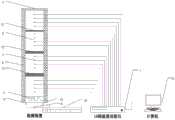
图1为本发明的结构示意图。FIG. 1 is a schematic structural diagram of the present invention.

图中各标号为:温控式加热片-1、导热块-2、铠装K型热电偶-3、闭孔式发泡橡胶隔热层-4、水冷头-5、水泵-6、16路温度巡检仪-7、计算机-8、水冷头出水口-9、水冷头进水口-10、第一待测样品-11、第二待测样品-12、第三待测样品-13、散热水箱-14。The labels in the figure are: temperature-controlled heating plate-1, heat-conducting block-2, armored K-type thermocouple-3, closed-cell foam rubber insulation layer-4, water-cooling head-5, water pump-6, 16-way temperature Inspection instrument-7, computer-8, water-cooled head water outlet-9, water-cooled head water inlet-10, first sample to be tested-11, second sample to be tested-12, third sample to be tested-13, cooling water tank -14.

具体实施方式Detailed ways

实施实例:如图1所示,一种薄板材料导热系数与界面热阻的测试系统,包括温控式加热片1、导热块2、铠装K型热电偶3、闭孔式发泡橡胶隔热层4、水冷头5、水泵6、16路温度巡检仪7、计算机8、水冷头出水口9、水冷头进水口10、厚度为δ1的第一待测样品11、厚度为δ2的第二待测样品12、厚度为δ3的第三待测样品13、散热水箱14;Example: As shown in Figure 1, a test system for thermal conductivity and interface thermal resistance of sheet materials, including temperature-controlledheating sheet 1,thermal block 2, armored K-type thermocouple 3, closed-cell foam rubberheat insulation layer 4. Water-cooledhead 5,water pump 6, 16-channeltemperature inspection instrument 7,computer 8, water-cooledhead water outlet 9, water-cooledhead water inlet 10, the first sample to be tested 11 with a thickness of δ1 , and the first sample with a thickness of δ2 . Two samples to be tested 12, a third sample to be tested 13 with a thickness of δ3 , and a coolingwater tank 14;

所述的温控式加热片1置于系统顶端并与导热块2紧密接触,用于对整个系统的热传导产生热量;温控式加热片1下面自上而下依次放置第一、第二、第三、第四块导热块2,将厚度为δ1的第一待测样品11、厚度为δ2的第二待测样品12和厚度为δ3的第三待测样品13自上而下依次放置于相邻两块导热块2之间,其中δ2=2δ1,δ3=3δ1;导热块2的长宽高均为5a,并于同一个表面自上而下均匀的打四个直径为1mm的孔,孔深2.5a,相邻两孔之间的孔心间距为a;每个孔中都放置直径为1mm的铠装K型热电偶3;铠装K型热电偶3通过16路温度巡检仪7读出所测温度,16路温度巡检仪7通过RS485通讯模块连接于计算机8,计算机8的显示系统将每支铠装K型热电偶3测出的温度数据自动显示并记录,最终可导出excel表格;系统最下端的导热块2通过导热膏接触于水冷头5,水冷头5设有水冷头出水口9和水冷头进水口10,水冷头出水口9和水冷头进水口10均通过管道与散热水箱14连接,水冷头5与散热水箱14通过设置在管道上的水泵6实现自动水循环,闭孔式发泡橡胶隔热层4紧贴于导热块2四周。由于导热块2为方形,闭孔式发泡橡胶隔热层4紧贴于导热块2的前后左右,以减小系统的侧面热量损耗。The temperature-controlledheating sheet 1 is placed at the top of the system and is in close contact with the heat-conductingblock 2 to generate heat for the heat conduction of the entire system; the temperature-controlledheating sheet 1 is placed in order from top to bottom. The third and fourth heat-conductingblocks 2, the first sample to be tested 11 with a thickness of δ1 , the second sample to be tested 12 with a thickness of δ2 , and the third sample to be tested 13 with a thickness of δ3 from top to bottom Placed between two adjacent heat-conductingblocks 2 in turn, where δ2 =2δ1 , δ3 =3δ1 ; the length, width, and height of the heat-conductingblocks 2 are both 5a, and they are evenly punched on the same surface from top to bottom. A hole with a diameter of 1mm, the hole depth is 2.5a, and the hole center spacing between two adjacent holes is a; each hole is placed with a 1mm diameter armored K-type thermocouple 3; armored K-type thermocouple 3 The measured temperature is read out through the 16-channeltemperature inspection instrument 7, and the 16-channeltemperature inspection instrument 7 is connected to thecomputer 8 through the RS485 communication module. The display system of thecomputer 8 displays the temperature data measured by each armored K-type thermocouple 3. Automatically display and record, and finally export an excel form; thethermal block 2 at the bottom of the system is in contact with thewater block 5 through thermal paste, and thewater block 5 is provided with awater block outlet 9 and awater block inlet 10. The water inlets 10 of the water-cooling head are connected to the coolingwater tank 14 through pipes. Thewater cooling head 5 and the coolingwater tank 14 realize automatic water circulation through thewater pump 6 arranged on the pipes. Since the heat-conductingblock 2 is square, the closed-cell foam rubberheat insulating layer 4 is closely attached to the front, rear, left and right of the heat-conductingblock 2 to reduce the side heat loss of the system.

优选地,所述的导热块2、水冷头5均采用紫铜制成,紫铜导热系数比较大,能有效减小了紫铜表面界面热阻对实验结果的影响。导热块2也可以换成其他已知导热系数材料,以实现该材料与待测物体间的界面热阻的测量。Preferably, the heat-conductingblock 2 and the water-coolinghead 5 are made of red copper, and the thermal conductivity of red copper is relatively large, which can effectively reduce the influence of the surface interface thermal resistance of red copper on the experimental results. The thermallyconductive block 2 can also be replaced with other materials with known thermal conductivity, so as to realize the measurement of the interface thermal resistance between the material and the object to be measured.

优选地,所述的导热块2上下接触表面保持平行,系统受到的压力不变,导热块2与相接触的待测样品之间的界面热阻与压力的大小成反比关系。Preferably, the upper and lower contact surfaces of the heat-conductingblock 2 are kept parallel, the pressure on the system remains unchanged, and the interface thermal resistance between the heat-conductingblock 2 and the contacting sample to be tested is inversely proportional to the pressure.

根据所述的一种薄板材料导热系数与界面热阻的测试系统的测试方法,包括如下步骤:According to the test method of a test system for thermal conductivity and interface thermal resistance of thin plate materials, the method includes the following steps:

A、将三个厚度分别为δ1、δ2和δ3的待测样品放置于系统导热块2之间,设置上方温控式加热片1的解热功率为定值,定义待测样品与与其相接触的导热块2之间的接触面的热阻为界面热阻,并启动下方水冷头5与散热水箱14之间的水循环装置,此时系统产生自上而下的热流,通过16路温度巡检仪7和计算机8实时记录16支铠装K型热电偶3的温度数据,当铠装K型热电偶3测得的温度可以维持5分钟不变时,即认为当前系统达到稳态热传导,当前所测数据为有效数据,通过不同高度导热块2的温度分布即可计算出通过该导热块2的热流密度,并通过最小二乘法拟合出的温度曲线,推算出每一个待测样品的上下表面的温度差,最终由傅里叶导热定律即可计算出每一个待测样品的热阻和导热块2与该待测样品上下接触处界面热阻的总和,所述的总和等于每一个待测样品的热阻加上2倍的导热块2与该待测样品接触处界面热阻;A. Place the three samples to be tested with thicknesses of δ1 , δ2 and δ3 respectively between the system heat-conductingblocks 2 , set the heating power of the upper temperature-controlledheating plate 1 as a constant value, define the sample to be tested and the The thermal resistance of the contact surface between the heat-conductingblocks 2 in contact with it is the interface thermal resistance, and the water circulation device between the water-coolinghead 5 and the coolingwater tank 14 is activated. Thetemperature inspection instrument 7 and thecomputer 8 record the temperature data of the 16 armored K-type thermocouples 3 in real time. When the temperature measured by the armored K-type thermocouples 3 can remain unchanged for 5 minutes, it is considered that the current system has reached a steady state Heat conduction, the currently measured data is valid data, the heat flux density through theheat conduction block 2 can be calculated through the temperature distribution of theheat conduction block 2 of different heights, and the temperature curve fitted by the least square method is used to calculate each test to be tested. The temperature difference between the upper and lower surfaces of the sample, and finally the thermal resistance of each sample to be tested and the sum of the interface thermal resistance at the upper and lower contact points between the thermallyconductive block 2 and the sample to be tested can be calculated by Fourier’s law of thermal conductivity. The sum is equal to The thermal resistance of each sample to be tested plus 2 times the thermal resistance of the interface at the contact point between the thermallyconductive block 2 and the sample to be tested;

B、根据待测样品的厚度δ、三个不同厚度的待测样品上下表面温度差Δt1,Δt2,Δt3以及关系式

Figure BDA0001350597870000081
可以计算出每一个待测样品的导热系数λx;式中:λx为待测样品的导热系数,λcu为导热块2的导热系数,k1、k2、k3、k4分别为第一、第二、第三、第四块导热块2的拟合温度分布曲线的斜率,Δt1、Δt2、Δt3分别为第一待测样品11、第二待测样品12、第三待测样品13上下表面温度差;B. According to the thickness δ of the sample to be tested, the temperature difference Δt1 , Δt2 , Δt3 between the upper and lower surfaces of the sample to be tested with three different thicknesses and the relational expression
Figure BDA0001350597870000081
The thermal conductivity λx of each sample to be tested can be calculated; in the formula: λx is the thermal conductivity of the sample to be tested, λcu is the thermal conductivity of the thermallyconductive block 2, and k1 , k2 , k3 , and k4 are respectively The slopes of the fitted temperature distribution curves of the first, second, third, and fourth thermallyconductive blocks 2, Δt1 , Δt2 , and Δt3 are the first sample to be tested 11 , the second sample to be tested 12 , the third sample to be tested 12 , and the third The temperature difference between the upper and lower surfaces of the sample to be tested 13;

C、根据待测样品的厚度δ、三个不同厚度的待测样品上下表面温度差Δt1,Δt2,Δt3以及关系式可以计算出每一个待测样品的界面热阻RT;式中:λcu为导热块2的导热系数,k1、k2、k3、k4分别为第一、第二、第三、第四块导热块2的拟合温度分布曲线的斜率,Δt1、Δt2、Δt3分别为第一待测样品11、第二待测样品12、第三待测样品13上下表面温度差。C. According to the thickness δ of the sample to be tested, the temperature differences Δt1 , Δt2 , Δt3 between the upper and lower surfaces of the sample to be tested with three different thicknesses and the relational expression The interface thermal resistance RT of each sample to be tested can be calculated; in the formula: λcu is the thermal conductivity of the thermallyconductive block 2 , k1 , k2 , k3 , and k4 are the first, second, third, The slopes of the fitting temperature distribution curve of the fourthheat conducting block 2, Δt1 , Δt2 , and Δt3 are the temperature differences between the upper and lower surfaces of thefirst sample 11 , thesecond sample 12 , and thethird sample 13 , respectively.

获得每一个待测样品的导热系数λx及每一个待测样品的界面热阻RT后,可以应用到各种相关的测试实验中,应用范围广。After obtaining the thermal conductivity λx of each sample to be tested and the interface thermal resistance RT of each sample to be tested, it can be applied to various related testing experiments with a wide range of applications.

以上结合附图对本发明的具体实施方式作了详细说明,但是本发明并不限于上述实施方式,在本领域普通技术人员所具备的知识范围内,还可以在不脱离本发明宗旨的前提下作出各种变化。The specific embodiments of the present invention have been described in detail above in conjunction with the accompanying drawings, but the present invention is not limited to the above-mentioned embodiments, and can also be made within the scope of knowledge possessed by those of ordinary skill in the art without departing from the spirit of the present invention. Various changes.

Claims (3)

1. A test system for heat conductivity coefficient and interface thermal resistance of sheet materials is characterized in that: comprises a temperature control heating sheet (1), a heat conducting block (2), an armored K-type thermocouple (3), a closed-cell type foamed rubber heat-insulating layer (4), a water cooling head (5), a water pump (6), a 16-path temperature polling instrument (7), a computer (8), a water cooling head water outlet (9), a water cooling head water inlet (10) and a thickness delta1A first sample (11) to be measured, having a thickness of delta2A second sample (12) to be measured, having a thickness delta3A third sample to be tested (13), a heat radiation water tank (14);
the temperature control type heating plate (1) is arranged at the top end of the system and is tightly contacted with the heat conducting block (2) and used for generating heat for heat conduction of the whole system; a first, a second, a third and a fourth heat conducting blocks (2) are sequentially arranged from top to bottom below the temperature control type heating sheet (1) and the thickness is delta1A first sample (11) to be measured, having a thickness of delta2And a second test sample (12) of thickness delta3The third sample (13) to be tested is sequentially placed between two adjacent heat conducting blocks (2) from top to bottom, wherein delta2=2δ1,δ3=3δ1(ii) a The length, the width and the height of the heat conducting block (2) are all 5a, four holes with the diameter of 1mm are uniformly drilled on the same surface from top to bottom, the hole depth is 2.5a, and the hole center distance between every two adjacent holes is a; a sheathed K-type thermocouple (3) with the diameter of 1mm is arranged in each hole; the armored K-type thermocouples (3) read the measured temperature through 16 temperature polling instruments (7), the 16 temperature polling instruments (7) are connected to the computer (8) through an RS485 communication module, and a display system of the computer (8) automatically displays and records the temperature data measured by each armored K-type thermocouple (3), and finally an excel table can be derived; the heat conducting block (2) at the lowest end of the system is contacted with the water cooling head through heat conducting paste(5) The water cooling head (5) is provided with a water cooling head water outlet (9) and a water cooling head water inlet (10), the water cooling head water outlet (9) and the water cooling head water inlet (10) are both connected with a heat dissipation water tank (14) through a pipeline, the water cooling head (5) and the heat dissipation water tank (14) realize automatic water circulation through a water pump (6) arranged on the pipeline, and the closed-cell type foamed rubber heat insulation layer (4) is tightly attached to the periphery of the heat conduction block (2);
the test method of the test system for the thermal conductivity and the interface thermal resistance of the sheet material comprises the following steps:
A. the three thicknesses are respectively delta1、δ2And delta3The sample to be measured is placed between heat conducting blocks (2) of the system, the antipyretic power of an upper temperature control type heating plate (1) is set to be a fixed value, the thermal resistance of a contact surface between the sample to be measured and the heat conducting block (2) in contact with the sample to be measured is defined as interface thermal resistance, a water circulation device between a lower water cooling head (5) and a heat dissipation water tank (14) is started, at the moment, the system generates heat flow from top to bottom, the temperature data of 16 armored K-type thermocouples (3) is recorded in real time through a 16-path temperature polling instrument (7) and a computer (8), when the temperature measured by the armored K-type thermocouples (3) can be kept unchanged for 5 minutes, the current system is considered to achieve steady heat conduction, the current measured data is effective data, the heat flow density of the heat conducting blocks (2) can be calculated through the temperature distribution of the heat conducting blocks (2) with different heights, and a temperature curve is fitted, calculating the temperature difference of the upper surface and the lower surface of each sample to be measured, and finally calculating the sum of the thermal resistance of each sample to be measured and the thermal resistance of the upper contact part and the lower contact part of the heat-conducting block (2) and the sample to be measured according to the Fourier heat conduction law, wherein the sum is equal to the thermal resistance of each sample to be measured plus 2 times of the thermal resistance of the interface of the contact part of the heat-conducting block (2) and the sample to be measured;
B. according to the thickness delta of the sample to be measured and the temperature difference delta t of the upper surface and the lower surface of the sample to be measured with three different thicknesses1,Δt2,Δt3And relational expression
Figure FDA0002211490690000021
The heat conductivity coefficient lambda of each sample to be measured can be calculatedx(ii) a In the formula: lambda [ alpha ]xTo be testedThermal conductivity of the sample, λcuIs the heat conductivity coefficient, k, of the heat-conducting block (2)1、k2、k3、k4The slope of the fitted temperature distribution curve of the first, second, third and fourth heat-conducting blocks (2), delta t1、Δt2、Δt3The temperature difference of the upper surface and the lower surface of a first sample to be detected (11), a second sample to be detected (12) and a third sample to be detected (13) respectively;
C. according to the thickness delta of the sample to be measured and the temperature difference delta t of the upper surface and the lower surface of the sample to be measured with three different thicknesses1,Δt2,Δt3And relational expression
Figure FDA0002211490690000022
The interface thermal resistance R of each sample to be measured can be calculatedT(ii) a In the formula: lambda [ alpha ]cuIs the heat conductivity coefficient, k, of the heat-conducting block (2)1、k2、k3、k4The slope of the fitted temperature distribution curve of the first, second, third and fourth heat-conducting blocks (2), delta t1、Δt2、Δt3The temperature difference of the upper surface and the lower surface of a first sample (11) to be detected, a second sample (12) to be detected and a third sample (13) to be detected.
2. The system for testing thermal conductivity and interfacial thermal resistance of a sheet material according to claim 1, wherein: the heat conducting block (2) and the water cooling head (5) are both made of red copper.
3. The system for testing thermal conductivity and interfacial thermal resistance of a sheet material according to claim 1, wherein: the upper and lower contact surfaces of the heat conduction block (2) are kept parallel, the pressure applied to the system is unchanged, and the thermal interface resistance between the heat conduction block (2) and a contacted sample to be tested is in inverse proportion to the pressure.
CN201710574561.6A2017-07-142017-07-14System and method for testing heat conductivity coefficient and interface thermal resistance of sheet materialActiveCN107688039B (en)

Priority Applications (1)

Application NumberPriority DateFiling DateTitle
CN201710574561.6ACN107688039B (en)2017-07-142017-07-14System and method for testing heat conductivity coefficient and interface thermal resistance of sheet material

Applications Claiming Priority (1)

Application NumberPriority DateFiling DateTitle
CN201710574561.6ACN107688039B (en)2017-07-142017-07-14System and method for testing heat conductivity coefficient and interface thermal resistance of sheet material

Publications (2)

Publication NumberPublication Date
CN107688039A CN107688039A (en)2018-02-13
CN107688039Btrue CN107688039B (en)2020-01-10

Family

ID=61152822

Family Applications (1)

Application NumberTitlePriority DateFiling Date
CN201710574561.6AActiveCN107688039B (en)2017-07-142017-07-14System and method for testing heat conductivity coefficient and interface thermal resistance of sheet material

Country Status (1)

CountryLink
CN (1)CN107688039B (en)

Families Citing this family (16)

* Cited by examiner, † Cited by third party
Publication numberPriority datePublication dateAssigneeTitle
CN108680600B (en)*2018-05-182021-05-07河北世纪建筑材料设备检验有限公司Novel material testing device and testing method
CN109001252A (en)*2018-06-282018-12-14西南电子技术研究所(中国电子科技集团公司第十研究所)Test device of thermal conductivity coefficient
CN109444211B (en)*2018-08-222021-10-15南京林业大学 Plate Thermal Conductivity Measuring Instrument Based on Copper Water Cooling System and Linear Fitting Method
CN109283217A (en)*2018-10-122019-01-29广州特种承压设备检测研究院 A kind of measuring method and device of thermal conductivity of graphene material
CN109283216A (en)*2018-10-122019-01-29广州特种承压设备检测研究院 A kind of measurement method and device of graphene material interface thermal resistance
TR201821010A2 (en)*2018-12-282020-07-21Dokuz Eyluel Ueniversitesi Rektoerluegue A measuring setup.
CN110658231A (en)*2019-09-182020-01-07浙江大学Steady-state test system and method for heat conductivity coefficient and interface thermal resistance of radiation heat dissipation correction type aviation background material
CN110988027A (en)*2019-12-172020-04-10中国石油大学(北京)Testing device and testing method for shale heat conduction parameters
CN111537555A (en)*2020-05-142020-08-14合肥工业大学Heat conductivity coefficient steady state method testing device and method suitable for vacuum glass beads
US11644432B2 (en)*2020-06-162023-05-09Thermtest, Inc.Method of characterizing, distinguishing, and measuring a contact region
CN114062420B (en)*2020-08-102023-09-08华为技术有限公司Device and method for testing heat conduction parameters
CN112485294B (en)*2020-11-302023-03-14航天特种材料及工艺技术研究所Heat conductivity meter-based method for evaluating heat loss ratio of side wall surface of central metering area
CN112730511A (en)*2020-12-282021-04-30合肥工业大学Detection device and method for measuring wall surface heat transfer coefficient of air duct
CN113419120B (en)*2021-05-082022-10-25同济大学 Method and system for measuring thermal resistance of dielectric film and metal interface
CN113514492B (en)*2021-06-022023-09-01中国电子产品可靠性与环境试验研究所((工业和信息化部电子第五研究所)(中国赛宝实验室))Method and device for measuring interface thermal resistance
CN113835006B (en)*2021-09-242025-01-17南方电网科学研究院有限责任公司Stepped temperature rise test method, device and application of thermosetting epoxy insulator

Citations (5)

* Cited by examiner, † Cited by third party
Publication numberPriority datePublication dateAssigneeTitle
JP2006145446A (en)*2004-11-242006-06-08Mitsubishi Electric Corp Thermal conductivity measuring device and thermal conductivity measuring method
CN102297877A (en)*2011-05-272011-12-28上海大学Device and method for measuring thermoelectric parameters of film
CN104181195A (en)*2014-08-282014-12-03电子科技大学Steady-state method-based heat conductivity coefficient measurement device
CN106153672A (en)*2016-06-082016-11-23东南大学Voluminous powder material thermal conductivity measurement apparatus based on one-dimensional heat conduction principle and method
CN106841297A (en)*2017-01-252017-06-13山东大学苏州研究院A kind of hot physical property testing device of multifunctional solid material and method

Patent Citations (5)

* Cited by examiner, † Cited by third party
Publication numberPriority datePublication dateAssigneeTitle
JP2006145446A (en)*2004-11-242006-06-08Mitsubishi Electric Corp Thermal conductivity measuring device and thermal conductivity measuring method
CN102297877A (en)*2011-05-272011-12-28上海大学Device and method for measuring thermoelectric parameters of film
CN104181195A (en)*2014-08-282014-12-03电子科技大学Steady-state method-based heat conductivity coefficient measurement device
CN106153672A (en)*2016-06-082016-11-23东南大学Voluminous powder material thermal conductivity measurement apparatus based on one-dimensional heat conduction principle and method
CN106841297A (en)*2017-01-252017-06-13山东大学苏州研究院A kind of hot physical property testing device of multifunctional solid material and method

Also Published As

Publication numberPublication date
CN107688039A (en)2018-02-13

Similar Documents

PublicationPublication DateTitle
CN107688039B (en)System and method for testing heat conductivity coefficient and interface thermal resistance of sheet material
CN103411996B (en)Solid material heat conductivity measurement mechanism and measuring method
CN101290299B (en)Variable thermal conductivity factor measuring apparatus and method
CN102297877B (en)Device and method for measuring thermoelectric parameters of film
CN100533133C (en) Heat pipe plate type thermal conductivity tester
CN101126729B (en) Measuring method of thermal conductivity of materials by double heat flow meter steady state method
FrancoAn apparatus for the routine measurement of thermal conductivity of materials for building application based on a transient hot-wire method
CN102384928B (en)Method for measuring thermal conductivity of high-conductivity thermal solid material
Zhang et al.A high-precision instrumentation of measuring thermal contact resistance using reversible heat flux
CN101303320A (en) A quasi-steady-state measuring instrument for solid thermal conductivity
CN104535609A (en)Device for determining heat-conductivity coefficient
Sponagle et al.Measurement of thermal interface conductance at variable clamping pressures using a steady state method
CN109490355A (en)A kind of method of test device of thermal conductivity coefficient and heat conducting coefficient measuring
CN109781780B (en)Simple and easy high heat conduction material coefficient of heat conductivity steady state test system
CN111474204B (en)Method for testing heat conductivity coefficient of cylindrical sample by punching method
CN104215660A (en)Method and system capable of simultaneously testing heat conduction coefficient and heat diffusion rate of solid material
CN114113203B (en) An easy-to-operate material thermal conductivity test method and device
CN101806761B (en)Instrument for measuring thermal conductivity coefficient of one-dimensional plane by using properties of graphite material
CN211978736U (en) A device for measuring thermal conductivity of composite phase change materials by steady-state method
CN111487282B (en)Device and method for measuring heterogeneous content in porous material with limited thickness
CN115616030B (en)Measurement method of heat conductivity coefficient
CN207133217U (en)It is a kind of to measure soil body thermal conductivity factor and the device of resistivity simultaneously
CN204086184U (en)A kind of system simultaneously can surveying solid material heat conductivity and thermal diffusivity
CN113670809A (en) A corrosion electrochemical measurement device and measurement method coupling heat transfer and flow field
CN107271476B (en)Motor iron core axial heat conductivity coefficient testing device and testing method

Legal Events

DateCodeTitleDescription
PB01Publication
PB01Publication
SE01Entry into force of request for substantive examination
GR01Patent grant
GR01Patent grant

[8]ページ先頭

©2009-2025 Movatter.jp