CN107688028B - Laser additive manufacturing lap joint rate online monitoring method - Google Patents
Laser additive manufacturing lap joint rate online monitoring methodDownload PDFInfo
- Publication number
- CN107688028B CN107688028BCN201710669368.0ACN201710669368ACN107688028BCN 107688028 BCN107688028 BCN 107688028BCN 201710669368 ACN201710669368 ACN 201710669368ACN 107688028 BCN107688028 BCN 107688028B
- Authority
- CN
- China
- Prior art keywords
- laser
- image
- additive manufacturing
- lap
- lap joint
- Prior art date
- Legal status (The legal status is an assumption and is not a legal conclusion. Google has not performed a legal analysis and makes no representation as to the accuracy of the status listed.)
- Active
Links
- 239000000654additiveSubstances0.000titleclaimsabstractdescription52
- 230000000996additive effectEffects0.000titleclaimsabstractdescription52
- 238000012544monitoring processMethods0.000titleclaimsabstractdescription43
- 238000004519manufacturing processMethods0.000titleclaimsabstractdescription38
- 238000000034methodMethods0.000titleclaimsabstractdescription30
- 238000012545processingMethods0.000claimsabstractdescription47
- 238000000605extractionMethods0.000claimsabstractdescription18
- 238000001914filtrationMethods0.000claimsabstractdescription11
- 230000009467reductionEffects0.000claimsabstractdescription8
- 238000007781pre-processingMethods0.000claimsabstract3
- 239000000463materialSubstances0.000claimsdescription20
- 239000000843powderSubstances0.000claimsdescription19
- 238000006073displacement reactionMethods0.000claimsdescription17
- 239000000758substrateSubstances0.000claimsdescription7
- 230000005540biological transmissionEffects0.000claimsdescription6
- 239000004065semiconductorSubstances0.000claimsdescription4
- 239000002893slagSubstances0.000claimsdescription4
- 238000009826distributionMethods0.000claimsdescription3
- 239000013307optical fiberSubstances0.000claimsdescription3
- 230000003287optical effectEffects0.000claims4
- 238000012937correctionMethods0.000abstractdescription3
- 238000013461designMethods0.000description8
- 230000007547defectEffects0.000description4
- 238000005516engineering processMethods0.000description4
- 230000000007visual effectEffects0.000description4
- 239000011159matrix materialSubstances0.000description3
- 238000005457optimizationMethods0.000description3
- 238000011161developmentMethods0.000description2
- 230000018109developmental processEffects0.000description2
- 230000008569processEffects0.000description2
- 238000003672processing methodMethods0.000description2
- 230000002159abnormal effectEffects0.000description1
- 238000004458analytical methodMethods0.000description1
- 230000009286beneficial effectEffects0.000description1
- 239000011248coating agentSubstances0.000description1
- 238000000576coating methodMethods0.000description1
- 239000011365complex materialSubstances0.000description1
- 230000007812deficiencyEffects0.000description1
- 238000001514detection methodMethods0.000description1
- 238000010586diagramMethods0.000description1
- 230000002708enhancing effectEffects0.000description1
- 230000004927fusionEffects0.000description1
- 230000010354integrationEffects0.000description1
- 238000004372laser claddingMethods0.000description1
- 239000000155meltSubstances0.000description1
- 239000002184metalSubstances0.000description1
- 238000012986modificationMethods0.000description1
- 230000004048modificationEffects0.000description1
- 239000011148porous materialSubstances0.000description1
- 238000011160researchMethods0.000description1
- 238000003892spreadingMethods0.000description1
- 230000007480spreadingEffects0.000description1
- 238000012360testing methodMethods0.000description1
- 230000009466transformationEffects0.000description1
Images

Classifications
- G—PHYSICS
- G01—MEASURING; TESTING
- G01N—INVESTIGATING OR ANALYSING MATERIALS BY DETERMINING THEIR CHEMICAL OR PHYSICAL PROPERTIES
- G01N21/00—Investigating or analysing materials by the use of optical means, i.e. using sub-millimetre waves, infrared, visible or ultraviolet light
- G01N21/84—Systems specially adapted for particular applications
- G01N21/88—Investigating the presence of flaws or contamination
- G01N21/95—Investigating the presence of flaws or contamination characterised by the material or shape of the object to be examined
Landscapes
- Physics & Mathematics (AREA)
- Health & Medical Sciences (AREA)
- Life Sciences & Earth Sciences (AREA)
- Chemical & Material Sciences (AREA)
- Analytical Chemistry (AREA)
- Biochemistry (AREA)
- General Health & Medical Sciences (AREA)
- General Physics & Mathematics (AREA)
- Immunology (AREA)
- Pathology (AREA)
- Laser Beam Processing (AREA)
Abstract
Translated fromChinese
Description
Translated fromChinese技术领域technical field
本发明属于激光增材制造在线监测技术领域,具体地,是一种针对激光增材制造搭接率的在线监测方法。The invention belongs to the technical field of on-line monitoring of laser additive manufacturing, in particular to an on-line monitoring method for the overlap ratio of laser additive manufacturing.
背景技术Background technique
增材制造作为与传统的等材、减材制造不同的一类加工方式,具有直接、快速、柔性化和智能化等优点,可有效进行复杂结构、复杂材料及小批量零部件的加工。激光增材制造因激光作为能量源,具有适用材料广泛、无需真空环境及成本相对较低等优势,广泛被应用于增材制造当中。As a kind of processing method different from traditional equivalent and subtractive manufacturing, additive manufacturing has the advantages of direct, fast, flexible and intelligent, and can effectively process complex structures, complex materials and small batch parts. Laser additive manufacturing is widely used in additive manufacturing due to the advantages of laser as an energy source, a wide range of applicable materials, no vacuum environment and relatively low cost.
激光增材制造,尤其是工业领域金属产品的增材制造,其质量的均一性较差,影响因素较多,其中的尺寸精度及缺陷问题一直影响着该技术的普及与应用。激光增材制造中,除去个别薄壁件为单道多层加工外,其余的应用领域,包括成形、修复、涂层等,均需要进行多道搭接加工。在多道加工中,过低的搭接率会导致增材部分表面凹凸不平,产生较高的粗糙度;过高的搭接率会导致增材部分高度异常增加,变形严重;同时,因热平衡与位姿变化等原因,增材制造每道甚至同一道的宽度也并不稳定;气孔、夹渣等缺陷也经常产生于道间的搭接处。因此,为获得较高尺寸精度及无缺陷的激光增材零部件,尤其在复杂结构或梯度材料的加工中,往往需要在搭接率的设计上耗费大量资源。Laser additive manufacturing, especially the additive manufacturing of metal products in the industrial field, has poor quality uniformity and many influencing factors. The dimensional accuracy and defects have always affected the popularization and application of this technology. In laser additive manufacturing, except that individual thin-walled parts are single-pass multi-layer processing, the rest of the application fields, including forming, repairing, coating, etc., all require multi-pass lap processing. In multi-pass processing, an excessively low lap ratio will cause the surface of the additive part to be uneven, resulting in higher roughness; an excessively high lap ratio will lead to an abnormal increase in the height of the additive part and serious deformation; at the same time, due to thermal balance Due to changes in pose and other reasons, the width of each pass or even the same pass in additive manufacturing is not stable; defects such as pores and slag inclusions often occur at the lap joints between passes. Therefore, in order to obtain high dimensional accuracy and defect-free laser additive parts, especially in the processing of complex structures or gradient materials, it is often necessary to spend a lot of resources on the design of the overlap ratio.
激光增材领域中,通过在线监测及反馈控制的方法来获得高质量零部件的研究已有一定的进展,但这些进展中还未有针对搭接率进行在线监测与反馈调节的有效方法。目前,激光增材制造中搭接率的确定依旧主要依靠大量的预试验,且无法根据加工情况来进行智能化的在线监测与反馈调节。In the field of laser additive, there has been some progress in the research of obtaining high-quality parts through online monitoring and feedback control, but there is no effective method for online monitoring and feedback adjustment of the overlap ratio in these developments. At present, the determination of the overlap ratio in laser additive manufacturing still mainly relies on a large number of pre-tests, and intelligent online monitoring and feedback adjustment cannot be carried out according to the processing conditions.
因此,针对搭接率设计需耗费大量资源,且无法进行在线监测与反馈调节的问题,现在缺乏行之有效的解决措施,而该问题对激光增材的加工质量及资源利用上又存在重要影响。所以,有必要提出能够在线监测激光增材制造搭接率的监测方法,以此来解决搭接率的设计问题以及在线监测与反馈调节中的在线监测问题。Therefore, there is a lack of effective solutions for the problem that the design of the overlap ratio requires a lot of resources, and online monitoring and feedback adjustment cannot be performed, and this problem has an important impact on the processing quality and resource utilization of laser additive materials. . Therefore, it is necessary to propose a monitoring method that can monitor the overlap ratio of laser additive manufacturing online, so as to solve the design problem of the overlap ratio and the online monitoring problem in online monitoring and feedback adjustment.
发明内容SUMMARY OF THE INVENTION
针对现有技术的不足,本发明提供了一种针对激光增材制造搭接率的在线监测方法,由此解决了增材制造中搭接率设计需耗费大量资源,以及在线监测与反馈调节中的在线监测问题,从而可以实时获取实际的搭接值与搭接率值,并以此为基础来进行搭接率的最优设计与反馈调节,该方法可以使激光增材制造质量更高、资源更节约。In view of the deficiencies of the prior art, the present invention provides an on-line monitoring method for the overlap ratio of laser additive manufacturing, thereby solving the problem that the design of the overlap ratio in the additive manufacturing consumes a lot of resources, and the process of on-line monitoring and feedback adjustment is solved. Therefore, the actual lap value and lap ratio value can be obtained in real time, and based on this, the optimal design and feedback adjustment of the lap ratio can be carried out. This method can make the laser additive manufacturing quality higher, Resources are more economical.
本发明的技术方案:Technical scheme of the present invention:
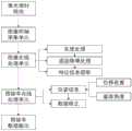
一种激光增材制造搭接率在线监测方法,该方法所用的激光增材制造搭接率在线监测系统,在原有在线监测系统的基础上增加图像在线处理单元和搭接率在线处理单元;原有在线监测系统包含激光器、激光头、位移装置、材料进给装置、图像同轴采集单元;An on-line monitoring method for overlap ratio of laser additive manufacturing. The on-line monitoring system for overlap ratio of laser additive manufacturing used in the method adds an image on-line processing unit and an on-line processing unit for overlap ratio on the basis of the original on-line monitoring system; There is an online monitoring system including laser, laser head, displacement device, material feeding device, and image coaxial acquisition unit;
所述的图像在线处理单元包括灰度处理模块、图像滤波降噪模块、宽度特征提取模块和搭接处特征提取模块;The image online processing unit includes a grayscale processing module, an image filtering noise reduction module, a width feature extraction module and an overlap feature extraction module;
所述的搭接率在线处理单元,根据图像在线处理单元的数据以及在线监测系统的位姿信息,对获取的搭接处特征进行实时修正,并在线得出实际搭接值及搭接率值;The lap rate online processing unit, according to the data of the image online processing unit and the pose information of the online monitoring system, performs real-time correction on the acquired lap feature, and obtains the actual lap value and the lap rate value online. ;
步骤如下:Proceed as follows:
(1)将激光头与基体的距离调至粉末汇聚处的上、下2mm范围内,通过标定板进行图像同轴采集单元的对焦,并标定图像与实际尺寸的比例,图像像素值与实际尺寸的比例为n:1;(1) Adjust the distance between the laser head and the substrate to within the range of 2mm above and below where the powder converges, focus the image coaxial acquisition unit through the calibration plate, and calibrate the ratio of the image to the actual size, and the pixel value of the image to the actual size. The ratio is n:1;
(2)激光头与基体或已增材部分的相对位移由位移装置控制,激光头与基体或已增材部分的位姿信息由位移装置和基体或已增材部分的角度共同决定,在基体或已增材部分上进行增材加工,并通过图像同轴采集单元实时采集激光熔池图像,采集帧速率范围为20~200fps;(2) The relative displacement of the laser head and the base or the added part is controlled by the displacement device, and the pose information of the laser head and the base or the added part is determined by the angle of the displacement device and the base or the added part. Or perform additive processing on the additive part, and collect the laser molten pool image in real time through the image coaxial acquisition unit, and the acquisition frame rate ranges from 20 to 200 fps;
(3)图像在线处理单元对采集到的图像进行预处理,包括灰度处理、图像滤波降噪、宽度特征提取和搭接处特征提取,处理时间为5~50ms;(3) The image online processing unit preprocesses the collected images, including grayscale processing, image filtering and noise reduction, width feature extraction and overlap feature extraction, and the processing time is 5-50ms;
灰度处理使原图像灰度直方图中的灰度分布范围至少压缩至原图的1/2;The grayscale processing compresses the grayscale distribution range in the grayscale histogram of the original image to at least 1/2 of the original image;
图像滤波降噪去除熔池区域外的粉末飞溅干扰,去除熔池区域内像素值小于10的粉末飞溅、熔池熔渣和熔池气泡干扰;Image filtering and noise reduction remove powder splash interference outside the molten pool area, and remove powder splash, molten pool slag and molten pool bubble interference with pixel values less than 10 in the molten pool area;
宽度特征提取可获得熔池垂直于扫描方向最大宽度的像素值L;Width feature extraction can obtain the pixel value L of the maximum width of the melt pool perpendicular to the scanning direction;
搭接处特征提取可获得平行于扫描方向的搭接处位置,以及该位置与当前增材部分熔池最左端之间垂直距离的像素值S;The lap feature extraction can obtain the position of the lap parallel to the scanning direction, and the pixel value S of the vertical distance between this position and the leftmost end of the molten pool of the current additive part;
(4)根据步骤(1)中的标定比例n:1,以及步骤(2)中的位姿信息,位姿信息包括激光头倾斜角度α及基体或已增材部分的倾斜角度β,将步骤(3)中提取的前一道宽度特征L1与当前搭接处特征S导入搭接率在线处理单元中,根据公式

上述技术方案中,所述激光器包括半导体激光器或Nd:YAG激光器,激光器与激光头的连接方式为光纤连接。In the above technical solution, the laser includes a semiconductor laser or an Nd:YAG laser, and the connection between the laser and the laser head is an optical fiber connection.
所述材料进给装置包括送粉装置、送丝装置或铺粉装置。The material feeding device includes a powder feeding device, a wire feeding device or a powder spreading device.
所述位移装置包括数控机床或机器人。The displacement device includes a CNC machine tool or a robot.
所述图像同轴采集单元包含内置于激光头内的45°分光镜、滤光片、镜头和相机,该分光镜可实现激光的正向传递与可见光的逆向传递,滤光片可以滤除强光及干扰光,镜头和相机可以清晰获取每一个时刻的激光增材熔池图像。The image coaxial acquisition unit includes a 45° beam splitter, a filter, a lens and a camera built into the laser head. The beam splitter can realize the forward transmission of the laser and the reverse transmission of the visible light, and the filter can filter out strong Light and interference light, lenses and cameras can clearly obtain the image of the laser additive melt pool at every moment.
本发明的有益效果:Beneficial effects of the present invention:
1.本发明能够对激光增材制造搭接率进行在线监测,实时获取实际搭接率值,且处理时间短,方法稳定可靠,既可用于常规情况下搭接率监控中的监测部分,又可用于复杂结构及梯度材料下搭接率的设计及优化。1. The present invention can monitor the overlap ratio of laser additive manufacturing on-line, obtain the actual overlap ratio value in real time, and the processing time is short, and the method is stable and reliable. It can be used for the design and optimization of the overlap ratio under complex structures and gradient materials.
2.本发明集成化程度高,可嵌入到目前监测系统中而不需新添加过多的硬件设备,并可实时采集宽度数据,针对熔池的视觉图像又可以进行更深层次的分析,如缺陷的在线检测等。2. The present invention has a high degree of integration, can be embedded into the current monitoring system without adding too many new hardware devices, can collect width data in real time, and can conduct deeper analysis on the visual image of the molten pool, such as defects. online detection, etc.
3.本发明适用性强,不受进给材料或基体材料属性、尺寸、表面状态等问题的限制,具有较好的适应性。3. The present invention has strong applicability, is not limited by the properties, dimensions, surface state of the feed material or the base material, and has good adaptability.
附图说明Description of drawings
图1为激光增材制造搭接率在线监测系统的结构示意图。Figure 1 is a schematic diagram of the structure of the laser additive manufacturing lap rate online monitoring system.
图2为激光增材制造搭接率在线监测方法的流程示意图。FIG. 2 is a schematic flow chart of the online monitoring method of the overlap ratio of laser additive manufacturing.
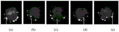
图3(a)(b)(c)(d)(e)为本发明实施例中316L基体及316L粉末加工过程中搭接率为0.83、0.67、0.50、0.31、0.05时的监测图像及搭接处特征。Fig. 3(a)(b)(c)(d)(e) are the monitoring images and the overlapping ratios of 0.83, 0.67, 0.50, 0.31 and 0.05 during the processing of the 316L matrix and the 316L powder in the embodiment of the present invention. junction features.
图中:1激光器;2位移装置;3激光头;4材料进给装置;In the picture: 1 laser; 2 displacement device; 3 laser head; 4 material feeding device;
5图像同轴采集单元;6计算机。5 image coaxial acquisition unit; 6 computer.
具体实施方式Detailed ways
为了使本发明的目的、技术方案及优点更加清楚明白,以下结合附图及实施例,对本发明进行进一步详细说明。应该理解,此处所描述的具体实施例仅用以解释本发明,并不用于限定本发明。此外,下面所描述的本发明各个实施方式中所涉及到的技术特征只要彼此之间未构成冲突就可以互相组合。In order to make the objectives, technical solutions and advantages of the present invention clearer, the present invention will be further described in detail below with reference to the accompanying drawings and embodiments. It should be understood that the specific embodiments described herein are only used to explain the present invention, but not to limit the present invention. In addition, the technical features involved in the various embodiments of the present invention described below can be combined with each other as long as they do not conflict with each other.
在激光增材制造中,搭接处易产生缺陷,且因热平衡与位姿变化等原因,增材制造每道甚至同一道的宽度均可能不同,尤其在复杂结构或梯度材料加工过程中,搭接率更加难以设计。随着激光增材的普及、激光头结构的优化以及视觉传感技术的发展,同轴视觉监测技术渐渐应用到了激光增材中,且各种图像处理方法也逐渐被尝试。因此,本发明充分利用现有的先进技术与算法,提出了激光增材制造搭接率的在线监测方法。In laser additive manufacturing, defects are prone to occur at the lap joint, and due to thermal balance and pose changes, the width of each pass or even the same pass in additive manufacturing may be different, especially in the processing of complex structures or gradient materials. Access rates are more difficult to design. With the popularization of laser additive, the optimization of laser head structure and the development of visual sensing technology, coaxial visual monitoring technology has been gradually applied to laser additive, and various image processing methods have been gradually tried. Therefore, the present invention makes full use of the existing advanced technologies and algorithms, and proposes an on-line monitoring method for the overlap ratio of laser additive manufacturing.
参看图1,本实施例硬件平台包括Referring to FIG. 1, the hardware platform of this embodiment includes
激光器1:所述激光器1在本实施例中为半导体激光器;Laser 1: The
位移装置2:所述位移装置2在本实施例中为六轴机器人;Displacement device 2: the
激光头3:所述激光头3在本实施例中为激光熔覆头;Laser head 3: The
材料进给装置4:所述材料进给装置4在本实施例中为送粉器;Material feeding device 4: the
图像同轴采集单元5:所述图像同轴采集单元中的视觉图像采集设备在本实施例中为CMOS相机;Image coaxial acquisition unit 5: the visual image acquisition device in the image coaxial acquisition unit is a CMOS camera in this embodiment;
计算机6:所述计算机6在本实施例中包含图像在线处理单元和搭接率在线处理单元。Computer 6: The
本实施例所采用的粉末与基体材料均为316L粉末,粉末直径为40~120μm,基体尺寸为120×30×10mm。The powder and matrix material used in this example are both 316L powder, the powder diameter is 40-120 μm, and the matrix size is 120×30×10mm.
由图2,实施例的步骤为:From Figure 2, the steps of the embodiment are:
(1)将激光头3与基体的距离调至粉末汇聚处,即15mm,通过标定板进行图像同轴采集单元的对焦,并标定图像与实际尺寸的比例,图像像素值与实际尺寸1mm的比例为130:1;(1) Adjust the distance between the
(2)激光头3与基体或已增材部分的相对位移由位移装置2控制,位姿信息由位移装置2和基体的相对角度决定,相对角度不应超过30°,图像同轴采集单元5实时采集激光熔池图像,采集帧速率为100fps;(2) The relative displacement between the
(3)图像在线处理单元对采集到的图像进行预处理,包括灰度处理、图像滤波降噪、宽度特征提取和搭接处特征提取,整体处理时间为每帧图像10~30ms;(3) The image online processing unit preprocesses the collected images, including grayscale processing, image filtering and noise reduction, width feature extraction and overlap feature extraction, and the overall processing time is 10-30ms per frame of image;
所述灰度处理,通过Gamma变换和对比度调整,使原图像灰度直方图中的灰度分布范围调节至3~150,以此来增强图像细节;In the grayscale processing, through Gamma transformation and contrast adjustment, the grayscale distribution range in the grayscale histogram of the original image is adjusted to 3-150, thereby enhancing image details;
所述图像滤波降噪,通过高斯滤波、中值滤波和小像素目标移除,去除熔池区域外的粉末飞溅干扰,去除熔池区域内像素值小于10的粉末飞溅、熔池熔渣和熔池气泡干扰;The image filtering noise reduction, through Gaussian filtering, median filtering and small pixel target removal, removes powder splash interference outside the molten pool area, and removes powder splashes, molten pool slag and molten pools with pixel values less than 10 in the molten pool area. Pool bubble interference;
所述宽度特征提取,通过像素加和运算,获得熔池垂直于扫描方向最大宽度的像素值L;The width feature extraction, through the pixel sum operation, obtains the pixel value L of the maximum width of the molten pool perpendicular to the scanning direction;
所述搭接处特征提取,通过像素加和运算,并选取熔池平行于扫描方向像素加和值的波谷作为搭接处位置,搭接处特征参看图3,该位置距前一道加工部分垂直距离的像素值为S;The feature extraction of the lap joint is performed by pixel addition operation, and the trough of the fusion pool parallel to the pixel summation value in the scanning direction is selected as the lap joint position. The lap joint feature is shown in Figure 3, and this position is perpendicular to the previous processing part. The pixel value of the distance is S;
(4)根据步骤(1)中的标定比例130:1,以及步骤(2)中的位姿信息,位姿信息包括激光头倾斜角度0°及基体或已增材部分的倾斜角度0°,将步骤(3)中提取的前一道宽度特征L1与当前搭接处特征S导入搭接率在线处理单元中,(4) According to the calibration ratio 130:1 in step (1) and the pose information in step (2), the pose information includes the inclination angle of the laser head 0° and the inclination angle of the base body or the added part 0°, The previous width feature L1 extracted in step (3 ) and the current overlap feature S are imported into the overlap ratio online processing unit,
根据公式
根据公式
该实施例中可确定图3(c)为理想搭接率(0.50),理想搭接率下的表面精度更高。该搭接率适用于316L基体与316L粉末,且基体水平,并与激光头垂直时的状态。因此,本发明提出的方法,可快速实现搭接率的有效监测,提升搭接率设计及优化的速度,以此来提高激光增材质量和效率。In this embodiment, it can be determined that Fig. 3(c) is the ideal overlap ratio (0.50), and the surface accuracy under the ideal overlap ratio is higher. The overlap ratio is applicable to the state when the 316L substrate and 316L powder are horizontal and vertical to the laser head. Therefore, the method proposed in the present invention can quickly realize the effective monitoring of the overlap ratio, and improve the speed of design and optimization of the overlap ratio, thereby improving the quality and efficiency of the laser additive.
本领域的技术人员容易理解,以上所述仅为本发明的较佳实例而已,并不用以限制本发明,凡在本发明的精神和原则之内所作的任何修改、等同替换和改进等,均应包含在本发明的保护范围之内。Those skilled in the art can easily understand that the above descriptions are only preferred examples of the present invention, and are not intended to limit the present invention. Any modifications, equivalent replacements and improvements made within the spirit and principles of the present invention will be should be included within the protection scope of the present invention.
Claims (10)


Priority Applications (1)
| Application Number | Priority Date | Filing Date | Title |
|---|---|---|---|
| CN201710669368.0ACN107688028B (en) | 2017-08-08 | 2017-08-08 | Laser additive manufacturing lap joint rate online monitoring method |
Applications Claiming Priority (1)
| Application Number | Priority Date | Filing Date | Title |
|---|---|---|---|
| CN201710669368.0ACN107688028B (en) | 2017-08-08 | 2017-08-08 | Laser additive manufacturing lap joint rate online monitoring method |
Publications (2)
| Publication Number | Publication Date |
|---|---|
| CN107688028A CN107688028A (en) | 2018-02-13 |
| CN107688028Btrue CN107688028B (en) | 2020-07-14 |
Family
ID=61153283
Family Applications (1)
| Application Number | Title | Priority Date | Filing Date |
|---|---|---|---|
| CN201710669368.0AActiveCN107688028B (en) | 2017-08-08 | 2017-08-08 | Laser additive manufacturing lap joint rate online monitoring method |
Country Status (1)
| Country | Link |
|---|---|
| CN (1) | CN107688028B (en) |
Families Citing this family (8)
| Publication number | Priority date | Publication date | Assignee | Title |
|---|---|---|---|---|
| CN108608119B (en)* | 2018-05-03 | 2021-04-27 | 苏州大学 | An online monitoring method for laser additive manufacturing |
| CN109136912B (en)* | 2018-09-11 | 2020-01-17 | 大连理工大学 | A method for on-line monitoring and negative feedback state identification of laser cladding defocus amount |
| CN108931535B (en)* | 2018-09-11 | 2021-01-05 | 大连理工大学 | Online monitoring method for laser additive manufacturing pore defects |
| CN108956609B (en)* | 2018-09-11 | 2021-04-20 | 大连理工大学 | Laser additive manufacturing powder utilization rate on-line monitoring method |
| CN110340363B (en)* | 2019-05-16 | 2022-12-06 | 西北工业大学 | Detection device and method for interaction of synchronous powder feeding laser additive manufacturing light powder |
| CN115056239B (en)* | 2022-07-06 | 2023-05-26 | 山东大学 | A membrane wall robot laser cladding method and system |
| CN115508376B (en)* | 2022-08-24 | 2025-02-14 | 上海交通大学 | Real-time monitoring system and method for processing status of laser cladding head |
| CN116638099B (en)* | 2023-05-30 | 2025-09-23 | 上海交通大学 | Online monitoring system and method for porosity defects in laser additive manufacturing overlap processing |
Citations (10)
| Publication number | Priority date | Publication date | Assignee | Title |
|---|---|---|---|---|
| JP2005014027A (en)* | 2003-06-24 | 2005-01-20 | Enshu Ltd | Welding image processing method, welding management system, feedback system for welding machine, butt line detection system |
| CN102191495A (en)* | 2010-03-05 | 2011-09-21 | 南昌航空大学 | Method for quickly preparing metal ceramic coating through laser induced composite fusioncast |
| CN102513708A (en)* | 2011-11-25 | 2012-06-27 | 湖南大学 | Active type integrating device of micro-pore monitoring and seam tracking in short-wavelength laser welding |
| CN103506756A (en)* | 2013-09-11 | 2014-01-15 | 上海交通大学 | Laser lap welding gap detecting system and laser lap welding gap detecting method based on molten pool image visual sensing |
| CN103604813A (en)* | 2013-12-05 | 2014-02-26 | 上海彩石激光科技有限公司 | Molten pool monitoring device for laser processing process |
| CN105335946A (en)* | 2015-09-22 | 2016-02-17 | 中国科学院西安光学精密机械研究所 | Histogram compactness transformation method |
| CN106338521A (en)* | 2016-09-22 | 2017-01-18 | 华中科技大学 | Additive manufacturing surface defect, internal defect and shape composite detection method and device |
| CN106404795A (en)* | 2016-10-26 | 2017-02-15 | 华中科技大学 | Infrared information-based metal additive manufacturing process control apparatus and method |
| CN106735210A (en)* | 2016-12-15 | 2017-05-31 | 南京中科煜宸激光技术有限公司 | A kind of control system and control method for powder feeding formula increasing material manufacturing equipment |
| CN106984813A (en)* | 2017-04-14 | 2017-07-28 | 华南理工大学 | A kind of melt-processed process coaxial monitoring method and device in selective laser |
- 2017
- 2017-08-08CNCN201710669368.0Apatent/CN107688028B/enactiveActive
Patent Citations (10)
| Publication number | Priority date | Publication date | Assignee | Title |
|---|---|---|---|---|
| JP2005014027A (en)* | 2003-06-24 | 2005-01-20 | Enshu Ltd | Welding image processing method, welding management system, feedback system for welding machine, butt line detection system |
| CN102191495A (en)* | 2010-03-05 | 2011-09-21 | 南昌航空大学 | Method for quickly preparing metal ceramic coating through laser induced composite fusioncast |
| CN102513708A (en)* | 2011-11-25 | 2012-06-27 | 湖南大学 | Active type integrating device of micro-pore monitoring and seam tracking in short-wavelength laser welding |
| CN103506756A (en)* | 2013-09-11 | 2014-01-15 | 上海交通大学 | Laser lap welding gap detecting system and laser lap welding gap detecting method based on molten pool image visual sensing |
| CN103604813A (en)* | 2013-12-05 | 2014-02-26 | 上海彩石激光科技有限公司 | Molten pool monitoring device for laser processing process |
| CN105335946A (en)* | 2015-09-22 | 2016-02-17 | 中国科学院西安光学精密机械研究所 | Histogram compactness transformation method |
| CN106338521A (en)* | 2016-09-22 | 2017-01-18 | 华中科技大学 | Additive manufacturing surface defect, internal defect and shape composite detection method and device |
| CN106404795A (en)* | 2016-10-26 | 2017-02-15 | 华中科技大学 | Infrared information-based metal additive manufacturing process control apparatus and method |
| CN106735210A (en)* | 2016-12-15 | 2017-05-31 | 南京中科煜宸激光技术有限公司 | A kind of control system and control method for powder feeding formula increasing material manufacturing equipment |
| CN106984813A (en)* | 2017-04-14 | 2017-07-28 | 华南理工大学 | A kind of melt-processed process coaxial monitoring method and device in selective laser |
Also Published As
| Publication number | Publication date |
|---|---|
| CN107688028A (en) | 2018-02-13 |
Similar Documents
| Publication | Publication Date | Title |
|---|---|---|
| CN107688028B (en) | Laser additive manufacturing lap joint rate online monitoring method | |
| CN108931535B (en) | Online monitoring method for laser additive manufacturing pore defects | |
| CN109778182B (en) | Laser cladding additive forming height online monitoring device and closed-loop control method | |
| CN109136912B (en) | A method for on-line monitoring and negative feedback state identification of laser cladding defocus amount | |
| CN105044154B (en) | The detection of material defect infrared thermal imaging and targeting removing method in laser metal forming | |
| CN106881462B (en) | A kind of on-line checking and optimization system for selective laser fusing forming defects | |
| CN106825914B (en) | A kind of integrated laser welding gun with welding line tracking function | |
| CN108956609B (en) | Laser additive manufacturing powder utilization rate on-line monitoring method | |
| CN112191993B (en) | Argon arc welding seam tracking system and method | |
| CN108489986A (en) | A kind of increasing material manufacturing on-line checking and restorative procedure | |
| US20080314878A1 (en) | Apparatus and method for controlling a machining system | |
| CN111189543B (en) | On-line calibration method for emissivity of thermal infrared imager in additive manufacturing | |
| CN111390168B (en) | On-line monitoring and negative feedback state identification method of laser melting deposition powder flow defocus amount | |
| CN109482874A (en) | Method and system based on Solidification Structures in image monitoring control laser gain material | |
| CN119413802A (en) | A method and system for detecting surface defects of workpiece based on optical technology | |
| CN103983203A (en) | Laser-cladding molten pool defocusing quantity measuring device and measuring method | |
| CN115383140A (en) | Blue laser fusion deposition aluminum alloy material deposition state monitoring system and method | |
| CN116329739A (en) | Device and method for controlling gap and step of laser welding seam based on visual sense and force sense multi-sensor coupling | |
| Colodrón et al. | FPGA-based measurement of melt pool size in laser cladding systems | |
| CN119772211A (en) | Laser electron beam composite additive manufacturing method and system | |
| CN204228119U (en) | A kind of laser melting coating molten bath defocusing amount measurement mechanism | |
| Wang et al. | Seam tracking and visual welding control in lap joint welding with Otsu’s thresholding and Gaussian line detection | |
| CN116638099B (en) | Online monitoring system and method for porosity defects in laser additive manufacturing overlap processing | |
| CN110616427A (en) | System and method for controlling laser cladding height of inner hole | |
| CN115326811B (en) | Laser melting deposition aluminum alloy thin-wall structure morphology defect monitoring system and method |
Legal Events
| Date | Code | Title | Description |
|---|---|---|---|
| PB01 | Publication | ||
| PB01 | Publication | ||
| SE01 | Entry into force of request for substantive examination | ||
| SE01 | Entry into force of request for substantive examination | ||
| GR01 | Patent grant | ||
| GR01 | Patent grant |