CN107671288B - Additive Manufacturing Apparatus and Method - Google Patents
Additive Manufacturing Apparatus and MethodDownload PDFInfo
- Publication number
- CN107671288B CN107671288BCN201710917246.9ACN201710917246ACN107671288BCN 107671288 BCN107671288 BCN 107671288BCN 201710917246 ACN201710917246 ACN 201710917246ACN 107671288 BCN107671288 BCN 107671288B
- Authority
- CN
- China
- Prior art keywords
- processing
- post
- head
- defect
- additive
- Prior art date
- Legal status (The legal status is an assumption and is not a legal conclusion. Google has not performed a legal analysis and makes no representation as to the accuracy of the status listed.)
- Active
Links
Images


Classifications
- B—PERFORMING OPERATIONS; TRANSPORTING
- B22—CASTING; POWDER METALLURGY
- B22F—WORKING METALLIC POWDER; MANUFACTURE OF ARTICLES FROM METALLIC POWDER; MAKING METALLIC POWDER; APPARATUS OR DEVICES SPECIALLY ADAPTED FOR METALLIC POWDER
- B22F10/00—Additive manufacturing of workpieces or articles from metallic powder
- B22F10/30—Process control
- B22F10/36—Process control of energy beam parameters
- B22F10/368—Temperature or temperature gradient, e.g. temperature of the melt pool
- B—PERFORMING OPERATIONS; TRANSPORTING
- B22—CASTING; POWDER METALLURGY
- B22F—WORKING METALLIC POWDER; MANUFACTURE OF ARTICLES FROM METALLIC POWDER; MAKING METALLIC POWDER; APPARATUS OR DEVICES SPECIALLY ADAPTED FOR METALLIC POWDER
- B22F10/00—Additive manufacturing of workpieces or articles from metallic powder
- B22F10/50—Treatment of workpieces or articles during build-up, e.g. treatments applied to fused layers during build-up
- B—PERFORMING OPERATIONS; TRANSPORTING
- B22—CASTING; POWDER METALLURGY
- B22F—WORKING METALLIC POWDER; MANUFACTURE OF ARTICLES FROM METALLIC POWDER; MAKING METALLIC POWDER; APPARATUS OR DEVICES SPECIALLY ADAPTED FOR METALLIC POWDER
- B22F10/00—Additive manufacturing of workpieces or articles from metallic powder
- B22F10/80—Data acquisition or data processing
- B22F10/85—Data acquisition or data processing for controlling or regulating additive manufacturing processes
- B—PERFORMING OPERATIONS; TRANSPORTING
- B22—CASTING; POWDER METALLURGY
- B22F—WORKING METALLIC POWDER; MANUFACTURE OF ARTICLES FROM METALLIC POWDER; MAKING METALLIC POWDER; APPARATUS OR DEVICES SPECIALLY ADAPTED FOR METALLIC POWDER
- B22F12/00—Apparatus or devices specially adapted for additive manufacturing; Auxiliary means for additive manufacturing; Combinations of additive manufacturing apparatus or devices with other processing apparatus or devices
- B22F12/90—Means for process control, e.g. cameras or sensors
- B—PERFORMING OPERATIONS; TRANSPORTING
- B33—ADDITIVE MANUFACTURING TECHNOLOGY
- B33Y—ADDITIVE MANUFACTURING, i.e. MANUFACTURING OF THREE-DIMENSIONAL [3-D] OBJECTS BY ADDITIVE DEPOSITION, ADDITIVE AGGLOMERATION OR ADDITIVE LAYERING, e.g. BY 3-D PRINTING, STEREOLITHOGRAPHY OR SELECTIVE LASER SINTERING
- B33Y10/00—Processes of additive manufacturing
- B—PERFORMING OPERATIONS; TRANSPORTING
- B33—ADDITIVE MANUFACTURING TECHNOLOGY
- B33Y—ADDITIVE MANUFACTURING, i.e. MANUFACTURING OF THREE-DIMENSIONAL [3-D] OBJECTS BY ADDITIVE DEPOSITION, ADDITIVE AGGLOMERATION OR ADDITIVE LAYERING, e.g. BY 3-D PRINTING, STEREOLITHOGRAPHY OR SELECTIVE LASER SINTERING
- B33Y30/00—Apparatus for additive manufacturing; Details thereof or accessories therefor
- B—PERFORMING OPERATIONS; TRANSPORTING
- B33—ADDITIVE MANUFACTURING TECHNOLOGY
- B33Y—ADDITIVE MANUFACTURING, i.e. MANUFACTURING OF THREE-DIMENSIONAL [3-D] OBJECTS BY ADDITIVE DEPOSITION, ADDITIVE AGGLOMERATION OR ADDITIVE LAYERING, e.g. BY 3-D PRINTING, STEREOLITHOGRAPHY OR SELECTIVE LASER SINTERING
- B33Y50/00—Data acquisition or data processing for additive manufacturing
- B33Y50/02—Data acquisition or data processing for additive manufacturing for controlling or regulating additive manufacturing processes
- B—PERFORMING OPERATIONS; TRANSPORTING
- B22—CASTING; POWDER METALLURGY
- B22F—WORKING METALLIC POWDER; MANUFACTURE OF ARTICLES FROM METALLIC POWDER; MAKING METALLIC POWDER; APPARATUS OR DEVICES SPECIALLY ADAPTED FOR METALLIC POWDER
- B22F10/00—Additive manufacturing of workpieces or articles from metallic powder
- B22F10/20—Direct sintering or melting
- B22F10/25—Direct deposition of metal particles, e.g. direct metal deposition [DMD] or laser engineered net shaping [LENS]
- B—PERFORMING OPERATIONS; TRANSPORTING
- B22—CASTING; POWDER METALLURGY
- B22F—WORKING METALLIC POWDER; MANUFACTURE OF ARTICLES FROM METALLIC POWDER; MAKING METALLIC POWDER; APPARATUS OR DEVICES SPECIALLY ADAPTED FOR METALLIC POWDER
- B22F12/00—Apparatus or devices specially adapted for additive manufacturing; Auxiliary means for additive manufacturing; Combinations of additive manufacturing apparatus or devices with other processing apparatus or devices
- B22F12/10—Auxiliary heating means
- B22F12/17—Auxiliary heating means to heat the build chamber or platform
- Y—GENERAL TAGGING OF NEW TECHNOLOGICAL DEVELOPMENTS; GENERAL TAGGING OF CROSS-SECTIONAL TECHNOLOGIES SPANNING OVER SEVERAL SECTIONS OF THE IPC; TECHNICAL SUBJECTS COVERED BY FORMER USPC CROSS-REFERENCE ART COLLECTIONS [XRACs] AND DIGESTS
- Y02—TECHNOLOGIES OR APPLICATIONS FOR MITIGATION OR ADAPTATION AGAINST CLIMATE CHANGE
- Y02P—CLIMATE CHANGE MITIGATION TECHNOLOGIES IN THE PRODUCTION OR PROCESSING OF GOODS
- Y02P10/00—Technologies related to metal processing
- Y02P10/25—Process efficiency
Landscapes
- Engineering & Computer Science (AREA)
- Chemical & Material Sciences (AREA)
- Materials Engineering (AREA)
- Manufacturing & Machinery (AREA)
- Automation & Control Theory (AREA)
- Analytical Chemistry (AREA)
- Laser Beam Processing (AREA)
- Powder Metallurgy (AREA)
Abstract
Description
Translated fromChinese技术领域technical field
本发明属于金属材料的增材制造领域,具体涉及一种增材制造装置,和采用该装置来进行增材制造的方法。The invention belongs to the field of additive manufacturing of metal materials, and particularly relates to an additive manufacturing device and a method for performing additive manufacturing by using the device.
背景技术Background technique
增材制造技术是根据产品三维模型,利用离散堆积原理,实现快速成形制造的技术,可以直接制造各种材料的复杂零部件,具有广泛的工业应用前景。但是,增材制造具有熔池温度高、快速凝固、温度梯度大的特点,这会导致成形工件内部形成较高的残余应力和冶金缺陷,导致变形,降低机械性能,特别是疲劳性能,影响了使用性能。上述现象在复杂、大型构件制造过程中尤为突出,是金属等材料的增材制造技术面临的主要技术瓶颈,阻碍了金属增材制造技术的工业化应用。针对上述难题的目前解决技术大多集中在工艺参数优化方面,工艺优化具有一定的改善效果,无法从根本上解决问题。对缺陷进行直接测量,并实时消除缺陷,直接提高部件的性能,是解决此类问题的根本解决办法。Additive manufacturing technology is a technology that realizes rapid prototyping manufacturing based on the three-dimensional model of the product and the principle of discrete accumulation. It can directly manufacture complex parts of various materials and has a wide range of industrial application prospects. However, additive manufacturing has the characteristics of high molten pool temperature, rapid solidification, and large temperature gradient, which will lead to the formation of high residual stress and metallurgical defects inside the formed workpiece, resulting in deformation, reduced mechanical properties, especially fatigue properties, affecting the Use performance. The above phenomenon is particularly prominent in the manufacturing process of complex and large-scale components. It is the main technical bottleneck faced by the additive manufacturing technology of metals and other materials, and hinders the industrial application of metal additive manufacturing technology. Most of the current solutions to the above problems focus on the optimization of process parameters, and the process optimization has a certain improvement effect, but cannot fundamentally solve the problem. Direct measurement of defects, elimination of defects in real time, and direct improvement of component performance are fundamental solutions to such problems.
通过在线无损检测,实时监测缺陷分布情况,为优化后续工艺提供参考,是提高加工质量的重要途径。现有的缺陷测量技术较多,如X射线无损检测技术、中子衍射检测技术、超声检测技术等,但是应用在增材制造过程中的较少,且大多是离线测量。仅有的几种增材在线监测技术(201710418485.X、201610436562.X)则仅仅局限在判断是否存在缺陷,对于已存缺陷的后续消除则无明确的技术路线。增材制造成本还比较高昂,存在缺陷的试样基本等同于报废,所以,检测出缺陷后,采用后处理方法消除缺陷,是提高增材制造质量,制造合格部件的根本途径。Through online non-destructive testing, real-time monitoring of defect distribution, providing reference for optimizing subsequent processes, is an important way to improve processing quality. There are many existing defect measurement technologies, such as X-ray non-destructive testing technology, neutron diffraction testing technology, ultrasonic testing technology, etc., but few of them are used in the additive manufacturing process, and most of them are offline measurements. The only few additive online monitoring technologies (201710418485.X, 201610436562.X) are only limited to judging whether there are defects, and there is no clear technical route for the subsequent elimination of existing defects. The cost of additive manufacturing is still relatively high, and defective samples are basically equivalent to scrapping. Therefore, after detecting defects, using post-processing methods to eliminate defects is the fundamental way to improve the quality of additive manufacturing and manufacture qualified parts.
201010147632.2专利将机械滚压方法与等离子弧增材制造结合,应用机械接触力直接作用于沉积层,改善应力和变形,精确控制沉积层形貌。该技术具有成本低的优势,但是不能对材料产生较明显的强化作用。短脉冲激光冲击强化技术能在作用构件表面产生加工硬化层和诱导残余压应力,作用深度可达几个毫米,同时衍生的动态应变时效效应使得材料内部产生高密度位错和析出相,形成钉扎位错,提高材料机械性能。由于激光束作用范围小,该加工方法具有加工位置精确、作用范围较小的特点。201610661086 .1已经提出在选择性激光烧结(SLM)中应用该技术。但是,上述两个种技术是未针对缺陷存在的局部区域进行处理,而是对整个沉积层整体式处理,使得加工时间大大延长,极大的降低了增材制造的效率。另有一种从搅拌摩擦焊接衍生而来的搅拌摩擦处理技术,通过搅拌使材料产生热塑性流动,抑制气孔和裂纹等界面缺陷,并形成重结晶作用,细化晶粒尺寸,提高机械性能。采用较大尺寸搅拌头时,该技术加工面积大,加工效率相对较高。因此,机械滚压、激光冲击强化和表面搅拌处理技术可用来优化金属构件成形和组织性能,提高构件表面硬度、耐磨性、抗腐蚀性能和疲劳寿命。以上技术都是独立发展的,将缺陷的检测技术、激光冲击强化或表面搅拌摩擦技术综合、有机的运用到增材制造中,并选择性的对缺陷局部区域进行后处理的方法和装备还未出现。The 201010147632.2 patent combines the mechanical rolling method with plasma arc additive manufacturing, and applies mechanical contact force to directly act on the deposited layer to improve stress and deformation and precisely control the morphology of the deposited layer. This technology has the advantage of low cost, but cannot produce obvious strengthening effect on the material. The short-pulse laser shock strengthening technology can produce a work-hardened layer and induce residual compressive stress on the surface of the active component, and the acting depth can reach several millimeters. At the same time, the derived dynamic strain aging effect causes high-density dislocations and precipitation phases inside the material to form nails. Bind dislocations and improve the mechanical properties of materials. Due to the small action range of the laser beam, the processing method has the characteristics of precise machining position and small action range. 201610661086.1 has been proposed to apply this technique in selective laser sintering (SLM). However, the above two technologies do not treat the local area where defects exist, but treat the entire deposition layer as a whole, which greatly prolongs the processing time and greatly reduces the efficiency of additive manufacturing. There is another friction stir processing technology derived from friction stir welding, which produces thermoplastic flow through stirring, suppresses interface defects such as pores and cracks, and forms recrystallization, refines grain size, and improves mechanical properties. When a larger size mixing head is used, the processing area of this technology is large, and the processing efficiency is relatively high. Therefore, mechanical rolling, laser shock strengthening and surface stirring treatment technologies can be used to optimize the forming and microstructure properties of metal components, and improve the surface hardness, wear resistance, corrosion resistance and fatigue life of components. The above technologies are all developed independently. The methods and equipment for comprehensively and organically applying defect detection technology, laser shock strengthening or surface friction stir technology to additive manufacturing, and selectively post-processing the local area of defects have not yet been established. Appear.
发明内容SUMMARY OF THE INVENTION
本发明是为了解决上述课题而进行的,目的在于提供一种高效高质的增材制造装置,和采用该装置来进行增材制造的方法。The present invention has been made to solve the above-mentioned problems, and an object of the present invention is to provide an efficient and high-quality additive manufacturing apparatus and a method for performing additive manufacturing using the same.
本发明为了实现上述目的,采用了以下方案。In order to achieve the above object, the present invention adopts the following solutions.
<增材制造装置><Additive Manufacturing Equipment>
本发明提供一种增材制造装置,其特征在于,包括:增材加工部,包含:高能束发生器和增材加工头,高能束发生器产生高能束,并传递给增材加工头,增材加工头按设定运动路径运动,并将待加工材料熔化以烧结制备沉积层;高速摄影部,包含:摄影头,该摄影头与增材加工头同步运动,对材料加工成型情况进行图像拍摄,获得材料图像信息;红外测温部,包含:测温头,该测温头与增材加工头同步运动,对材料的温度分布情况进行检测,获得材料温度分布信息;驱动部,包含:第一机械臂、第二机械臂、以及三维运动机构;第一机械臂的前端用于安装增材加工头、摄影头和测温头,并且驱动增材加工头、摄影头和测温头同步运动;光学测量部,进行材料表面缺陷和成形尺寸的检测,获得检测信息;内部缺陷探测部,包含:探测头和探测分析器,探测头贴近沉积层进行面扫描,探测分析器根据探测头的扫描情况分析确定沉积层内部的缺陷类型和位置;三维运动机构的运动端用于安装探测头,并且驱动该探测头运动;后处理部,用于对材料缺陷区域采用相应的后处理方式进行加工处理,包括:后处理加工头,该后处理加工头能够移动至贴近材料缺陷区域上表面,并逐步对材料缺陷区域进行缺陷消除处理;后处理方式包括:机械碾压处理、激光冲击强化处理、和搅拌摩擦加工处理中的至少一种后处理方式;第二机械臂的前端用于安装后处理加工头,并且驱动该后处理加工头运动;控制部,控制增材加工部、高速摄影部、红外测温部、第一机械臂、光学测量部、以及内部缺陷探测部的运行,获取材料图像信息、材料温度分布信息、检测信息、以及缺陷类型和位置信息,并基于这些信息判断是否存在缺陷和缺陷是否可消除,并在存在可消除的缺陷的情况下,确定缺陷处理区域、每个区域所对应的后处理路径和后处理方式,控制后处理部沿着相应的后处理路径,并采取相应的后处理方式分别对各个缺陷处理区域进行加工处理;在存在不可消除的缺陷的情况下,停止加工并报警。The present invention provides an additive manufacturing device, which is characterized by comprising: an additive processing unit, comprising: a high-energy beam generator and an additive processing head, the high-energy beam generator generates a high-energy beam and transmits it to the additive processing head, and the The material processing head moves according to the set motion path, and melts the material to be processed to prepare the deposition layer by sintering; the high-speed camera section includes: a camera head, which moves synchronously with the additive processing head to capture images of the material processing and forming conditions , to obtain the material image information; the infrared temperature measurement part, including: the temperature measurement head, which moves synchronously with the additive processing head, detects the temperature distribution of the material, and obtains the material temperature distribution information; the driving part, including: the first A robotic arm, a second robotic arm, and a three-dimensional motion mechanism; the front end of the first robotic arm is used to install the additive processing head, the camera head and the temperature measuring head, and drive the additive processing head, the camera head and the temperature measuring head to move synchronously ;Optical measurement part, to detect material surface defects and forming dimensions, and obtain detection information; Internal defect detection part, including: detection head and detection analyzer, the detection head is close to the deposition layer to perform surface scanning, and the detection analyzer is based on the scanning of the detection head. The situation analysis determines the defect type and position inside the deposition layer; the moving end of the three-dimensional motion mechanism is used to install the probe head and drive the probe head to move; the post-processing part is used to process the material defect area with corresponding post-processing methods , including: post-processing processing head, which can move to the upper surface of the material defect area, and gradually carry out defect elimination processing on the material defect area; post-processing methods include: mechanical rolling treatment, laser shock strengthening treatment, and At least one post-processing method in friction stir processing; the front end of the second robotic arm is used to install the post-processing processing head, and drive the post-processing processing head to move; the control unit controls the additive processing unit, the high-speed photography unit, the infrared The operation of the temperature measurement unit, the first robotic arm, the optical measurement unit, and the internal defect detection unit, obtains material image information, material temperature distribution information, inspection information, and defect type and location information, and judges whether there are defects and Whether the defect can be eliminated, and if there is a defect that can be eliminated, determine the defect processing area, the post-processing path and post-processing method corresponding to each area, control the post-processing unit to follow the corresponding post-processing path, and take corresponding measures. The post-processing method is used to process each defect processing area; in the case of irreparable defects, the processing is stopped and an alarm is issued.
本发明所涉及的增材制造装置,还可以具有这样的特征:控制部让测试员输入待加工材料的材料类型,并且基于材料类型按照如下方式确定后处理方式:在材料类型属于金属材料,并且沉积层宽度大于2mm的情况下,采用机械碾压处理方式,控制后处理加工头中的机械滚轮对沉积层的表面施加机械力的作用,使表面平整,压实内部孔隙缺陷,机械滚轮的行走速度为0.5~5 m/min,下压压强大于材料的屈服强度;在材料类型属于高强度金属材料的情况下,采用激光冲击强化处理方式,控制后处理加工头中的激光冲击头的约束层覆盖平整沉积层,激光束透过约束层产生等离子体冲击波,冲击沉积层,使材料产生塑性变形,消除沉积层内部的孔隙缺陷和应力集中,并强化沉积层材料,激光冲击头的行走速度范围0.5-5m/min,激光功率密度为0.5~5 GW/cm2;在材料类型属于低强度有色金属材料情况下,采用搅拌摩擦加工处理方式,控制后处理加工头中的搅拌头搅拌材料,消除内部几何形状类缺陷,搅拌头转速:铝合金/镁合金为1500~2000转/分,铜合金为2000~3000转/分,搅拌深度等于沉积层深度;在其它情况下,选用机械碾压处理方式。The additive manufacturing device according to the present invention may further have the feature that: the control unit allows the tester to input the material type of the material to be processed, and determines the post-processing method based on the material type in the following manner: if the material type belongs to a metal material, and When the width of the deposited layer is greater than 2mm, the mechanical rolling treatment method is used to control the mechanical roller in the post-processing head to exert mechanical force on the surface of the deposited layer, so as to make the surface smooth, compact the internal pore defects, and move the mechanical roller. The speed is 0.5~5 m/min, and the lower pressure is stronger than the yield strength of the material; when the material type is a high-strength metal material, the laser shock strengthening treatment method is used to control the constraint layer of the laser shock head in the post-processing head. Covering the flat deposition layer, the laser beam passes through the confinement layer to generate a plasma shock wave, which impacts the deposition layer, causing plastic deformation of the material, eliminating pore defects and stress concentration inside the deposition layer, and strengthening the deposition layer material. The speed range of the laser impact head 0.5-5m/min, laser power density is 0.5~5 GW/cm2 ; in the case of low-strength non-ferrous metal materials, friction stir processing is used to control the stirring head in the post-processing head to stir the material, eliminate the Defects in internal geometry, stirring head rotation speed: aluminum alloy/magnesium alloy is 1500~2000 rpm, copper alloy is 2000~3000 rpm, and the stirring depth is equal to the depth of the deposition layer; in other cases, use mechanical rolling treatment Way.
本发明所涉及的增材制造装置,还可以具有这样的特征:在采用搅拌摩擦加工处理方式的情况下,当沉积层厚度小于5mm时,对于铝合金镁合金材料,搅拌头的加工行走速度不超过0.8m/min,对于铜合金材料,搅拌头的加工行走速度不超过0.5m/min。The additive manufacturing device involved in the present invention may also have the following characteristics: in the case of using the friction stir processing method, when the thickness of the deposited layer is less than 5 mm, for the aluminum alloy magnesium alloy material, the processing speed of the stirring head does not increase. If it exceeds 0.8m/min, for copper alloy materials, the processing speed of the stirring head should not exceed 0.5m/min.
本发明所涉及的增材制造装置,还可以具有这样的特征:在采用机械碾压方式不能消除沉积层缺陷,沉积层上表面平面度误差大于1mm,并且材料为钛合金、高强钢、或高温合金的情况下,进一步采用激光冲击强化处理方式;在采用机械碾压方式不能消除沉积层缺陷,沉积层上表面平面度误差大于1mm,并且材料为铝合金、镁合金、或铜合金的情况下,进一步采用搅拌摩擦加工处理方式。The additive manufacturing device involved in the present invention may also have the following characteristics: the defects of the deposition layer cannot be eliminated by mechanical rolling, the flatness error of the upper surface of the deposition layer is greater than 1 mm, and the material is titanium alloy, high-strength steel, or high temperature In the case of alloys, the laser shock strengthening treatment method is further adopted; in the case that the defects of the deposition layer cannot be eliminated by the mechanical rolling method, the flatness error of the upper surface of the deposition layer is greater than 1mm, and the material is aluminum alloy, magnesium alloy, or copper alloy. , and further adopt the friction stir processing method.
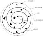
本发明所涉及的增材制造装置,还可以具有这样的特征:控制部按照如下方式确定缺陷处理区域和后处理路径:在材料缺陷为局部簇状分布的多缺陷或单个缺陷的情况下,用包含该局部区域所有缺陷的最小圆周的直径d表示缺陷区域特征尺寸,缺陷处理区域为该圆所包含的区域,后处理路径为绕此区域最大直径为d的螺旋线,扫描起始位置为该螺旋线的中心点;在材料缺陷为链状分布的多缺陷的情况下,用覆盖局部区域所有缺陷的长条状区域的长度l和宽度w表示缺陷区域特征尺寸,缺陷处理区域为该长条状区域,后处理路径为该长条状区域,扫描起始位置为长条状区域的端点之一。The additive manufacturing apparatus according to the present invention may further have the feature that the control unit determines the defect processing area and the post-processing path as follows: when the material defects are multiple defects or single defects distributed in local clusters, use The diameter d of the smallest circle containing all defects in the local area represents the characteristic size of the defect area, the defect processing area is the area contained in the circle, the post-processing path is a spiral line with a maximum diameter d around this area, and the scanning starting position is the The center point of the helix; in the case of multiple defects with a chain-like distribution of material defects, the length l and width w of the long strip covering all defects in the local area represent the characteristic size of the defect area, and the defect processing area is the strip. The post-processing path is the strip-shaped area, and the scanning start position is one of the endpoints of the strip-shaped area.
本发明所涉及的增材制造装置,还可以具有这样的特征:控制部在不存在缺陷的情况下,控制各部进行后续沉积层的烧结、检测和后处理。The additive manufacturing device according to the present invention may also have the feature that the control part controls each part to perform sintering, detection and post-processing of the subsequent deposition layer when there is no defect.
本发明所涉及的增材制造装置,还可以具有这样的特征:控制部在一层或多层沉积层被烧结后,控制增材加工头、高速摄像部、和红外测温部都停止工作,进一步控制第一机械臂将增材加工头、摄影头和测温头一起移动至烧结工作区域之外;控制部在探测结束后,控制探测头停止工作,并控制三维运动机构将探测头移动至烧结工作区域之外进行复位;控制部,还控制后处理部在所有缺陷都加工处理完成后停止工作,并控制第二机械臂将后处理加工头移动至烧结工作区域之外进行复位。The additive manufacturing device involved in the present invention may also have the following feature: the control unit controls the additive processing head, the high-speed camera unit, and the infrared temperature measurement unit to stop working after one or more deposition layers are sintered, Further control the first robotic arm to move the additive processing head, the camera head and the temperature measuring head together to the outside of the sintering work area; after the detection, the control part controls the probe to stop working, and controls the three-dimensional motion mechanism to move the probe to The reset is performed outside the sintering working area; the control unit also controls the post-processing unit to stop working after all defects are processed, and controls the second robotic arm to move the post-processing processing head outside the sintering working area for reset.
本发明所涉及的增材制造装置,还可以具有这样的特征:控制部控制各部循环进行沉积层的烧结、检测和后处理直至整个制造过程结束。The additive manufacturing apparatus according to the present invention may also have the feature that the control unit controls each unit to cyclically perform sintering, detection and post-processing of the deposited layer until the entire manufacturing process is completed.
本发明所涉及的增材制造装置,还可以包括:基板,承载待加工材料,具有加热功能,对加工环境预热,抑制应力集中。The additive manufacturing device involved in the present invention may further include: a substrate, which supports the material to be processed, has a heating function, preheats the processing environment, and suppresses stress concentration.
<增材制造方法><Additive Manufacturing Method>
本发明还提供了一种增材制造方法,采用如权利要求1至9中任意一样的增材制造来进行增材制造,其特征在于:The present invention also provides an additive manufacturing method, using the additive manufacturing as in any one of claims 1 to 9 for additive manufacturing, characterized in that:
采用增材加工部中的高能束发生器将高能束传递给增材加工头,并让增材加工头按设定运动路径进行运动,将待加工材料熔化以制备沉积层;高速摄影部中的摄影头与增材加工头同步运动,对材料加工成型情况进行图像拍摄,获得材料图像信息;同时,红外测温部中的测温头与增材加工头同步运动,对材料的温度分布情况进行检测,获得材料温度分布信息;采用光学测量部进行材料表面缺陷和成形尺寸的检测,获得检测信息;采用三维运动机构驱动内部缺陷探测部中的探测头贴近沉积层进行面扫描,并采用探测分析器根据探测头的扫描情况分析确定沉积层内部的缺陷类型和位置;采用后处理部对材料缺陷区域采用相应的后处理方式进行加工处理,包括:采用第二机械臂驱动后处理加工头移动至贴近材料缺陷区域上表面,并逐步对材料缺陷区域进行缺陷消除处理;采用控制部控制增材加工部、高速摄影部、红外测温部、第一机械臂、光学测量部、以及内部缺陷探测部的运行,获取材料图像信息、材料温度分布信息、检测信息、以及缺陷类型和位置信息,并基于这些信息判断是否存在缺陷和缺陷是否可消除,并在存在可消除的缺陷的情况下,确定缺陷处理区域、每个区域所对应的后处理路径和后处理方式,控制后处理部沿着相应的后处理路径,并采取相应的后处理方式分别对各个缺陷处理区域进行加工处理;在存在不可消除的缺陷的情况下,停止加工并报警。The high-energy beam generator in the additive processing department is used to transmit the high-energy beam to the additive processing head, and the additive processing head is moved according to the set motion path, and the material to be processed is melted to prepare the deposition layer; The camera moves synchronously with the additive processing head to capture images of the material processing and forming conditions to obtain material image information; at the same time, the temperature measuring head and the additive processing head in the infrared temperature measurement section move synchronously to monitor the temperature distribution of the material. Inspection to obtain material temperature distribution information; use the optical measuring part to detect material surface defects and forming dimensions to obtain inspection information; use a three-dimensional motion mechanism to drive the probe head in the internal defect detection part to be close to the deposition layer to scan the surface, and use detection analysis The detector analyzes and determines the defect type and position inside the deposition layer according to the scanning situation of the detector head; uses the post-processing part to process the material defect area with corresponding post-processing methods, including: using the second robotic arm to drive the post-processing processing head to move to Close to the upper surface of the material defect area, and gradually eliminate the defect area of the material; use the control unit to control the additive processing unit, the high-speed photography unit, the infrared temperature measurement unit, the first robotic arm, the optical measurement unit, and the internal defect detection unit operation, obtain material image information, material temperature distribution information, inspection information, and defect type and location information, and based on these information to judge whether there is a defect and whether the defect can be eliminated, and if there is a defect that can be eliminated, determine the defect The processing area, the post-processing path and post-processing method corresponding to each area, control the post-processing unit to follow the corresponding post-processing path, and adopt the corresponding post-processing method to process each defect processing area respectively; In case of defects, stop processing and alarm.
发明的作用与效果The role and effect of the invention
1)本发明实现了在加工过程中的缺陷在线检测-反馈控制-选择性后处理,可以保证加工后的构件内部冶金缺陷和变形被控制在合理范围内,大大提高加工构件的成品率;1) The present invention realizes on-line detection of defects in the processing process - feedback control - selective post-processing, which can ensure that the internal metallurgical defects and deformation of the processed components are controlled within a reasonable range, and greatly improve the yield of the processed components;
2)本发明通过对增材沉积层缺陷集中区域进行选择性的机械碾压、激光冲击强化或搅拌摩擦加工处理,减少或消除了沉积层内部的缺陷,大幅减少了构件在加工过程中的缺陷、变形和开裂产生的可能性,保证了构件的质量和尺寸精度,同时由于选择性的特征,减少了后处理的时间,可以提高加工效率;2) The present invention reduces or eliminates the defects inside the deposition layer by selectively mechanical rolling, laser shock strengthening or friction stir processing on the defect-concentrated area of the additive deposition layer, and greatly reduces the defects of the components during the processing. The possibility of deformation and cracking ensures the quality and dimensional accuracy of the components, and at the same time, due to the selective characteristics, the post-processing time is reduced, and the processing efficiency can be improved;
3)本发明通过对增材沉积层进行实时的机械滚压、激光冲击强化或搅拌摩擦加工处理,利用机械辗压产生的塑性变形,使沉积层表面平整,利用激光冲击强化的动态应变时效效应,在沉积层内部产生了高密度的位错,促进第二强化相析出,或利用搅拌摩擦加工的重结晶效应细化晶粒,提高了加工构件的机械性能。3) The present invention makes the surface of the deposition layer smooth by performing real-time mechanical rolling, laser shock strengthening or friction stir processing on the additive deposition layer, using the plastic deformation generated by mechanical rolling, and using the dynamic strain aging effect of laser shock strengthening. , resulting in high-density dislocations inside the deposition layer, promoting the precipitation of the second strengthening phase, or using the recrystallization effect of friction stir processing to refine the grains and improve the mechanical properties of the processed components.
附图说明Description of drawings
图1是本发明实施例涉及的增材制造装置的结构框图;FIG. 1 is a structural block diagram of an additive manufacturing apparatus according to an embodiment of the present invention;
图2是本发明实施例涉及的增材制造装置的结构示意图;FIG. 2 is a schematic structural diagram of an additive manufacturing device involved in an embodiment of the present invention;
图3是本发明实施例涉及的簇状分布缺陷的扫描路径示意图;3 is a schematic diagram of a scanning path of a cluster-like distribution defect involved in an embodiment of the present invention;
图4是本发明实施例涉及的链状分布缺陷的扫描路径示意图。FIG. 4 is a schematic diagram of a scanning path of a chain-like distribution defect involved in an embodiment of the present invention.
具体实施方式Detailed ways
以下参照附图对本发明所涉及的增材制造装置及方法作详细阐述。The additive manufacturing apparatus and method involved in the present invention will be described in detail below with reference to the accompanying drawings.
<实施例><Example>
如图1所示,增材制造装置100包括:工作台101、基板102、增材加工部103、高速摄影部104、红外测温部105、驱动部106、光学测量部107、内部缺陷探测部108、后处理部109、以及控制部110。As shown in FIG. 1 , the
如图2所示,基板102放置在工作台101上,用于承载待加工材料,具有加热功能,对加工环境进行预热,抑制应力集中。As shown in FIG. 2 , the
增材加工部103包含:高能束发生器103a和增材加工头103b。高能束发生器103a能够产生高能束,并传递给增材加工头103b;增材加工头103b按设定运动路径运动,在运动过程中熔化待加工材料,烧结形成所需形状和尺寸的沉积层S。这里,高能束发生器103a可以为激光器、电子束发生装置、电弧电源、等离子弧电源;相应的,增材加工头103b对应为激光光学加工头、电磁透镜、电弧焊枪、等离子弧焊枪。本实施例中,增材加工头103b还包括填充材料的装置,如填丝装置或送粉装置。The
高速摄影部104用于检测熔池形态,它包含:摄影头104a和图像处理传输器。摄影头104a与增材加工头103b同步运动,对材料加工成型情况进行图像拍摄;图像处理传输器对拍摄数据进行处理并将处理后的材料图像信息传送给控制部110。The high-
红外测温部105用于检测熔池温度,它包含:测温头和处理传输器。测温头与增材加工头103b同步运动,对材料的温度分布情况进行检测;温度处理传输器对检测到的数据进行处理并将处理后的材料温度分布信息传送给控制部110。The infrared
驱动部106包含:第一机械臂106a、第二机械臂106b、以及三维运动机构106c。第一机械臂106a和第二机械臂106b均安装在工作台101的侧旁,它们的前端都能够进行自由运动并覆盖整个工作台101。三维运动机构106c安装在工作台101的侧部上,运动端能够覆盖整个工作台101进行自由运动。The driving
第一机械臂106a的前端用于安装增材加工头103b、摄影头104a和测温头,并且驱动增材加工头103b、摄影头104a和测温头同步运动。The front end of the first
光学测量部107固定安装在基板102上方,并且朝向沉积层S,用于进行材料表面缺陷和成形尺寸的检测,获得检测信息。The
内部缺陷探测部108用于对材料内部缺陷进行探测,它包含:探测头108a、探测发生器108b以及探测分析传输器。探测头108a贴近沉积层S进行面扫描;探测发生器108b将能量传送给探测头108a;探测分析传输器根据探测头108a的扫描情况分析确定沉积层S内部的缺陷类型和位置,并将缺陷类型和位置信息发送给控制部110。这里,探测头108a为超声或X射线探头,相应的,探测发生器108b超声或X射线发生器。The internal
三维运动机构106c的运动端用于安装探测头108a,并且驱动该探测头108a运动;The moving end of the three-
后处理部109用于对材料缺陷区域采用相应的后处理方式进行加工处理,包括:后处理加工头109a和后处理装置。后处理加工头109a能够移动至贴近材料缺陷区域上表面,并逐步对材料缺陷区域进行后处理以消除缺陷,本实施例中,后处理加工头109a包含:机械滚轮、激光冲击头、以及搅拌头三种加工头,每次处理时,根据处理方式选择其中一种加工头;后处理装置用于给后处理加工头109a提供能量,它包括电源、脉冲激光器、以及机械装置;这里,后处理方式包括:机械碾压处理、激光冲击强化处理、和搅拌摩擦加工处理中的至少一种后处理方式,并且可以自动切换。The
第二机械臂106b的前端用于安装后处理加工头109a,并且驱动后处理加工头109a运动;The front end of the second
控制部110与增材加工部103、高速摄影部104、红外测温部105、第一机械臂106a、光学测量部107、以及内部缺陷探测部108相通讯连接,用于控制它们的运行,获取材料图像信息、材料温度分布信息、检测信息、以及缺陷类型和位置信息,并基于这些信息判断是否存在缺陷和缺陷是否可消除,在存在可消除的缺陷的情况下,确定缺陷处理区域、每个区域所对应的后处理路径和后处理方式,控制后处理部109沿着相应的后处理路径,并采取相应的后处理方式分别对各个缺陷处理区域进行加工处理;在存在不可消除的缺陷的情况下,停止加工并报警。本实施例中,控制部110为计算机,它还能够实时显示加工状况信息,并让操作者输入或选择相应的信息,即、通过控制部110可以设定被其控制的各设备的工艺参数及其工作流程。The
基于以上结构,采用增材制造装置100来进行增材制造的方法为:Based on the above structure, the method for performing additive manufacturing using the
(1)高能束发生器103a产生高能束,并将能量传递至增材加工头103b,通过增材加工头103b熔化材料形成熔池,在第一机械臂106a的驱动下,增材加工头103b按设定运动路径运动,沉积层S逐步形成,根据运动路径的不同得到不同形状的沉积层S;(1) The high-
(2)在烧结过程中,第一机械臂106a驱动摄影头104a和测温头随着增材加工头103b同步进行熔池运动,对材料加工成型情况进行图像拍摄,获得材料图像信息,同时,对材料的温度分布情况进行检测,获得材料温度分布信息,由图像处理传输器和温度处理传输器将这些信息反馈至控制部110;(2) During the sintering process, the first
(3)烧结一层或多层后,增材加工头103b、摄影头104a和测温头停止工作,并随第一机械臂106a移动至烧结工作区域之外;(3) After sintering one or more layers, the
(4)光学测量部107进行表面缺陷和成形尺寸的检测,并将检测到的材料温度分布信息反馈至控制部110;(4) The
(5)内部缺陷探测部108开始工作,探测头108a在三维运动机构106c的驱动下贴近沉积层S进行面扫描,探测分析器根据扫描情况分析确定沉积层S内部的缺陷类型和位置确定,并将这些信息反馈至控制部110;(5) The internal
(6)检测完成后,探测头108a停止工作,并随三维运动机构106c移动至烧结工作区域之外;(6) After the detection is completed, the
(7)控制部110综合分析沉积层S缺陷形态和具体位置,根据缺陷尺寸和数量判断是否可消除。如可消除,确定缺陷位置,规划后处理加工头109a的扫描路径(后处理路径)、扫描范围(缺陷处理区域)及后处理方式及工艺参数,从而执行后处理工序。如不能消除,停止加工并报警。若无缺陷,则进行下一层的烧结。如为孔隙类缺陷,当其尺寸超过后处理加工头109a的有效工作尺寸时,则判定尺寸不能消除,停止加工并报警;如为小尺寸的孔隙或裂纹等缺陷,则进行下一步后处理加工过程;(7) The
(8)控制部110确定最优的后处理扫描路径和扫描范围:如图3所示,在材料缺陷为局部簇状分布的多缺陷或单个缺陷,用包含该局部区域所有缺陷的最小圆周的直径d表示缺陷区域特征尺寸,扫描区域位置即为该圆包含的区域,扫描路径为绕此区域最大直径为d的螺旋线,扫描起始位置为螺旋线的中心点;如图4所示,链状分布的多缺陷,用覆盖局部区域所有缺陷的长条状区域的长度l和宽度w表示缺陷区域特征尺寸,扫描区域位置为该长条状区域,扫描路径即为此长条状区域,扫描起始位置为长条状区域的端点之一。(8) The
(9)控制部110根据如下分类确定最优的后处理方式和工艺参数:(9) The
l 机械碾压技术:适用于全部金属,同时适用于中大尺寸沉积层S,如宽度大于2mm的沉积层S,工作过程:机械滚轮对沉积表面施加机械力的作用,使表面平整,压实内部孔隙缺陷;参数选择如下:1)加工头行走速度范围0.5~5 m/min;2)加工头下压压强:取决于材料种类,一般应大于材料的屈服强度;l Mechanical rolling technology: suitable for all metals, and also suitable for medium and large size deposition layers S, such as deposition layers S with a width greater than 2mm, working process: mechanical rollers apply mechanical force to the deposition surface to make the surface smooth and compact Internal pore defects; the parameters are selected as follows: 1) The traveling speed of the processing head ranges from 0.5 to 5 m/min; 2) The down pressure of the processing head: depends on the type of material, generally it should be greater than the yield strength of the material;
l 激光冲击强化处理技术:钛合金、高温合金、高强钢等高强度材料,沉积层S宽度小于0.5mm;工作过程:激光冲击头的约束层覆盖平整沉积层S,脉冲激光器工作,激光束透过约束层产生等离子体冲击波,冲击沉积层S,使材料产生塑性变形,消除沉积层S内部的孔隙缺陷和应力集中,并强化沉积层S材料;工艺参数如下:1)加工头行走速度范围0.5~5m/min;2)激光能量参数:0.5~5 GW/cm2;l Laser shock strengthening treatment technology: high-strength materials such as titanium alloys, high-temperature alloys, and high-strength steel, the width of the deposition layer S is less than 0.5mm; working process: the confinement layer of the laser shock head covers the flat deposition layer S, the pulsed laser works, and the laser beam penetrates The plasma shock wave generated by the over-confined layer impacts the deposition layer S, causing plastic deformation of the material, eliminating pore defects and stress concentration inside the deposition layer S, and strengthening the material of the deposition layer S; the process parameters are as follows: 1) The travel speed range of the processing head is 0.5 ~5m/min; 2) Laser energy parameters: 0.5~5 GW/cm2 ;
l 表面搅拌摩擦处理技术:铝合金、镁合金、铜合金等低强度有色金属材料,同时适用于厚壁结构,如沉积层S宽度大于5mm,且表面平整,参数选择如下:1)搅拌头转速:铝合金/镁合金1500-2000转/分,铜合金2000-3000转/分;2)搅拌深度:完全取决于沉积层S深度,沉积层S深度是多少搅拌深度就是多少,在本技术中一般小于5mm;l Surface friction stir treatment technology: low-strength non-ferrous metal materials such as aluminum alloy, magnesium alloy, copper alloy, etc., and suitable for thick-walled structures, such as the width of the deposited layer S is greater than 5mm, and the surface is smooth, the parameters are selected as follows: 1) Stirring head speed : Aluminum alloy/magnesium alloy 1500-2000 rpm, copper alloy 2000-3000 rpm; 2) Stirring depth: completely depends on the depth of the deposition layer S, the depth of the deposition layer S is as much as the stirring depth, in this technology Generally less than 5mm;
3)加工头行走速度:取决于沉积层S深度和材料类型,一般而言,沉积层S厚度小于5mm时,铝合金镁合金最大可达0.8m/min,铜合金最大可达0.5m/min;3) The walking speed of the processing head: depends on the depth of the deposition layer S and the type of material. Generally speaking, when the thickness of the deposition layer S is less than 5mm, the aluminum alloy magnesium alloy can reach a maximum of 0.8m/min, and the copper alloy can reach a maximum of 0.5m/min. ;
l 复合式后处理方式:l Composite post-processing method:
a)机械碾压+激光冲击强化方法:钛合金、高强钢、高温合金,机械碾压不能消除沉积层S全部缺陷、沉积层S上表面平面度误差大于1mm,加工过程为先机械碾压,然后激光冲击;a) Mechanical rolling + laser shock strengthening method: titanium alloys, high-strength steels, high-temperature alloys, mechanical rolling cannot eliminate all the defects of the deposition layer S, and the flatness error of the upper surface of the deposition layer S is greater than 1mm. The processing process is mechanical rolling first. Then laser shock;
b)机械碾压+表面搅拌摩擦处理方法:铝合金、镁合金、铜合金,机械碾压不能消除沉积层S全部缺陷、沉积层S上表面平面度误差大于1mm;加工过程为先机械碾压,然后表面搅拌摩擦处理;b) Mechanical rolling + surface friction stir treatment method: aluminum alloy, magnesium alloy, copper alloy, mechanical rolling cannot eliminate all defects of the deposition layer S, and the flatness error of the upper surface of the deposition layer S is greater than 1mm; the processing process is mechanical rolling first , and then surface friction stir treatment;
(10)后处理工序具体过程为:后处理加工头109a在第二机械臂106b驱动下移动至贴近沉积层S上表面,后处理加工头109a按照(8)和(9)中确定的方案逐步扫描冲击沉积层S,并进行后处理,直至将沉积层S缺陷区域全部表面全部加工完毕,然后,后处理加工头109a随第二机械臂106b复位;(10) The specific process of the post-processing process is as follows: the
(11)增材加工头103b运动至沉积层S上方,开始下一层沉积层S的加工,循环上述过程,直至加工完成。(11) The
以上说明对本发明而言只是说明性的,而非限制性的,本领域普通技术人员的理解,在不脱离权利要求所限定的精神和范围的情况下,可根据上述揭示内容做出变更、修饰或等效,但都将落入本发明的保护范围内。The above description is only illustrative rather than restrictive for the present invention. Those of ordinary skill in the art will understand that changes and modifications can be made according to the above disclosure without departing from the spirit and scope defined by the claims. or equivalent, but all fall within the protection scope of the present invention.
如上,本方案将在线无损检测技术和选择性后处理方法引入增材制造工艺中,通过有机结合形成新型的增材制造方法和装备,有力的解决增材制造缺陷和材料性能难题,同时具有较短的加工工艺时间,可以突破金属增材制造技术瓶颈,实现高质高效的增材制造。As above, this solution introduces the online non-destructive testing technology and selective post-processing method into the additive manufacturing process, and forms a new additive manufacturing method and equipment through organic combination, which effectively solves the problems of additive manufacturing defects and material performance, and has relatively high performance. The short processing time can break through the bottleneck of metal additive manufacturing technology and achieve high-quality and efficient additive manufacturing.
以上实施例仅仅是对本发明技术方案所做的举例说明。本发明所涉及的增材制造装置及方法并不仅仅限定于在以上实施例中所描述的结构,而是以权利要求所限定的范围为准。本发明所属领域技术人员在该实施例的基础上所做的任何修改或补充或等效替换,都在本发明所要求保护的范围内。The above embodiments are merely examples to illustrate the technical solutions of the present invention. The additive manufacturing apparatus and method involved in the present invention are not limited only to the structures described in the above embodiments, but are subject to the scope defined by the claims. Any modifications or additions or equivalent substitutions made by those skilled in the art of the present invention on the basis of this embodiment fall within the scope of protection claimed by the present invention.
Claims (7)
Translated fromChinesePriority Applications (1)
| Application Number | Priority Date | Filing Date | Title |
|---|---|---|---|
| CN201710917246.9ACN107671288B (en) | 2017-09-27 | 2017-09-27 | Additive Manufacturing Apparatus and Method |
Applications Claiming Priority (1)
| Application Number | Priority Date | Filing Date | Title |
|---|---|---|---|
| CN201710917246.9ACN107671288B (en) | 2017-09-27 | 2017-09-27 | Additive Manufacturing Apparatus and Method |
Publications (2)
| Publication Number | Publication Date |
|---|---|
| CN107671288A CN107671288A (en) | 2018-02-09 |
| CN107671288Btrue CN107671288B (en) | 2020-01-24 |
Family
ID=61137789
Family Applications (1)
| Application Number | Title | Priority Date | Filing Date |
|---|---|---|---|
| CN201710917246.9AActiveCN107671288B (en) | 2017-09-27 | 2017-09-27 | Additive Manufacturing Apparatus and Method |
Country Status (1)
| Country | Link |
|---|---|
| CN (1) | CN107671288B (en) |
Families Citing this family (33)
| Publication number | Priority date | Publication date | Assignee | Title |
|---|---|---|---|---|
| CN108274002B (en)* | 2018-04-25 | 2022-03-11 | 吉林大学 | A laser additive manufacturing synchronization monitoring system |
| DE102018207520A1 (en)* | 2018-05-15 | 2019-11-21 | Airbus Defence and Space GmbH | Method for producing a component |
| CN108705083A (en)* | 2018-05-31 | 2018-10-26 | 华中科技大学 | A kind of real-time pre-heating system of selective melting powder and method based on multi-laser |
| CN108802165B (en)* | 2018-06-29 | 2020-12-18 | 武汉大学 | Additive processing system and method with spectral ultrasonic composite online detection function |
| CN108872197B (en)* | 2018-06-29 | 2020-12-01 | 武汉大学 | Additive processing system and method with spectral mass spectrometry composite online detection function |
| CN108788152B (en)* | 2018-06-29 | 2019-08-20 | 武汉大学 | Additive processing system and method with online detection function of environmental components |
| CN109604808B (en)* | 2018-12-11 | 2020-10-09 | 东北大学 | A friction stir additive manufacturing device and method applying cooling |
| JP7321624B2 (en) | 2018-12-25 | 2023-08-07 | エルジー・ケム・リミテッド | Molding apparatus and molded product manufacturing method |
| CN109759707B (en)* | 2019-01-13 | 2020-08-14 | 大连理工大学 | A laser-TIG composite heat source additive manufacturing method for aluminum alloy ring parts |
| CN110328364B (en)* | 2019-06-24 | 2020-11-24 | 华中科技大学 | A method and device for additive manufacturing of ceramics and their composites |
| CN110284084B (en)* | 2019-06-28 | 2021-09-28 | 江苏理工学院 | Plastic forming method for high-strength wear-resistant aluminum alloy plate |
| CN110315082B (en)* | 2019-07-30 | 2021-01-19 | 华中科技大学 | Metal part manufacturing system and method of micro-cast laser shock texture |
| CN110465661A (en)* | 2019-07-30 | 2019-11-19 | 武汉大学深圳研究院 | A kind of SLM metal increasing material manufacturing defect real-time detection method and detection device |
| US11312076B2 (en)* | 2019-09-23 | 2022-04-26 | The Boeing Company | Apparatuses for additively manufacturing an object from a powder material |
| CN111014882B (en)* | 2019-12-18 | 2022-04-01 | 内蒙古第一机械集团股份有限公司 | Electric arc additive manufacturing method for locking pin body |
| CN111007142B (en)* | 2019-12-19 | 2022-03-15 | 华中科技大学 | An electromagnetic-assisted online microstructure detection and control system and method |
| CN111036911B (en)* | 2019-12-31 | 2021-10-19 | 西安交通大学 | A method for removing pore defects in metal additive manufacturing components based on online monitoring |
| US10871471B1 (en)* | 2020-01-02 | 2020-12-22 | The Boeing Company | Systems and methods for inspecting additively manufactured components |
| CN111230109B (en)* | 2020-01-17 | 2021-09-14 | 广东省科学院中乌焊接研究所 | Additive manufacturing equipment and additive manufacturing method |
| CN111531026A (en)* | 2020-05-21 | 2020-08-14 | 西安邮电大学 | an incremental forming system |
| CN111644728B (en)* | 2020-05-25 | 2021-07-20 | 武汉理工大学 | Direct high-precision forming method for rigid impact-assisted arc additive hot work die repair |
| CN111687413B (en)* | 2020-06-08 | 2022-03-11 | 岳阳珞佳智能科技有限公司 | Real-time monitoring device, forming equipment and method for laser near-net forming |
| CN111804913A (en)* | 2020-06-15 | 2020-10-23 | 上海航天设备制造总厂有限公司 | 3D printing apparatus integrating molding and detection |
| CN112719578B (en)* | 2020-12-25 | 2021-12-14 | 中国科学院重庆绿色智能技术研究院 | Vacuum environment laser additive manufacturing metal evaporation control method and device |
| CN112846183B (en)* | 2021-02-25 | 2022-04-15 | 岳阳珞佳智能科技有限公司 | Laser-ultrasonic-plasma composite cleaning method and device for metal additive manufacturing layer by layer |
| CN113231650B (en)* | 2021-05-25 | 2023-10-17 | 广东中科德弗激光科技有限公司 | Laser and friction-assisted material adding device and method |
| CN114289734B (en)* | 2021-07-02 | 2024-08-20 | 杭州德迪智能制造有限公司 | Three-dimensional printer and powder spreading defect detection method |
| CN114378309B (en)* | 2021-12-29 | 2025-01-28 | 天翼物联科技有限公司 | A complex component flexible manufacturing system and a complex component flexible manufacturing method |
| CN115055853B (en)* | 2022-07-01 | 2024-02-20 | 南京航空航天大学 | A method for cleaning failed parts for additive remanufacturing repair of molds |
| CN115213427A (en)* | 2022-07-19 | 2022-10-21 | 季华实验室 | Additive manufacturing method and product |
| CN116748352B (en)* | 2023-08-14 | 2023-11-07 | 江苏新恒基特种装备股份有限公司 | Metal pipe bending machine processing parameter monitoring control method, system and storage medium |
| CN117123891B (en)* | 2023-10-24 | 2024-01-12 | 北京航科精机科技有限公司 | Spare part increase and decrease material repairing method and device based on intelligent control of mechanical arm |
| CN117600761A (en)* | 2023-11-22 | 2024-02-27 | 南京工业大学 | A method to eliminate pore defects in aluminum/magnesium alloy additive components |
Citations (4)
| Publication number | Priority date | Publication date | Assignee | Title |
|---|---|---|---|---|
| CN104404509A (en)* | 2014-11-28 | 2015-03-11 | 中南大学 | Metal laser melting additive manufacturing method |
| CN105345003A (en)* | 2015-12-16 | 2016-02-24 | 阳江市五金刀剪产业技术研究院 | Material increase manufacturing device for knife scissors |
| CN106141439A (en)* | 2016-08-13 | 2016-11-23 | 中北大学 | Eliminate the laser-impact device of laser fusion molded article residual stress |
| CN106363171A (en)* | 2016-09-29 | 2017-02-01 | 中北大学 | Selective laser melting forming molten bath real-time monitoring device and monitoring method |
Family Cites Families (4)
| Publication number | Priority date | Publication date | Assignee | Title |
|---|---|---|---|---|
| ES2404505T3 (en)* | 2004-12-28 | 2013-05-28 | Nippon Light Metal Company, Ltd. | Method to produce an aluminum composite |
| DE102012011217B4 (en)* | 2012-06-06 | 2025-08-21 | Concept Laser Gmbh | Device for the production of three-dimensional components |
| US9310188B2 (en)* | 2014-08-20 | 2016-04-12 | Arcam Ab | Energy beam deflection speed verification |
| CN105154870B (en)* | 2015-09-01 | 2018-01-23 | 广东工业大学 | A kind of metal parts Stress Control 3D printing reproducing method |
- 2017
- 2017-09-27CNCN201710917246.9Apatent/CN107671288B/enactiveActive
Patent Citations (4)
| Publication number | Priority date | Publication date | Assignee | Title |
|---|---|---|---|---|
| CN104404509A (en)* | 2014-11-28 | 2015-03-11 | 中南大学 | Metal laser melting additive manufacturing method |
| CN105345003A (en)* | 2015-12-16 | 2016-02-24 | 阳江市五金刀剪产业技术研究院 | Material increase manufacturing device for knife scissors |
| CN106141439A (en)* | 2016-08-13 | 2016-11-23 | 中北大学 | Eliminate the laser-impact device of laser fusion molded article residual stress |
| CN106363171A (en)* | 2016-09-29 | 2017-02-01 | 中北大学 | Selective laser melting forming molten bath real-time monitoring device and monitoring method |
Also Published As
| Publication number | Publication date |
|---|---|
| CN107671288A (en) | 2018-02-09 |
Similar Documents
| Publication | Publication Date | Title |
|---|---|---|
| CN107671288B (en) | Additive Manufacturing Apparatus and Method | |
| JP7002142B2 (en) | How to control the deformation and accuracy of parts in parallel during the additive manufacturing process | |
| CN110421169B (en) | A method for online repair of defects in metal additive manufacturing process | |
| CN112264618B (en) | In-situ laser shock reinforced composite additive manufacturing system and method, printed parts | |
| CN107102061A (en) | High-energy beam addition and subtraction of metal materials-on-line laser ultrasonic testing composite processing method | |
| CN108838397B (en) | An online monitoring method for laser additive manufacturing | |
| CN109226755B (en) | Additive manufacturing apparatus and method for improving bonding strength between deposition layers of additive components | |
| CN112195468A (en) | Damaged blade repairing method and device of blisk based on double laser beams | |
| CN111203639B (en) | A system and method for monitoring the transfer of filler wire and droplet in double-laser beams and double-side synchronous welding based on high-speed camera | |
| CN110666341A (en) | A kind of bifurcated tail nozzle double laser beam impact forging hybrid welding method and device | |
| CN110441395A (en) | A kind of the water logging ultrasound on-line detecting system and method for metal increasing material manufacturing process | |
| CN112958875A (en) | Device and method for eliminating residual stress of electric arc additive manufacturing through composite energy impact | |
| CN111172529A (en) | Defect control method for cast aluminum alloy structural member in laser coaxial powder feeding repair process | |
| CN107931844A (en) | A kind of impeller chip off-falling destressing laser-impact forges reproducing method and device | |
| CN113943908A (en) | Device for strengthening laser cladding layer by high-frequency vibration rolling and using method thereof | |
| CN118893301B (en) | Additive manufacturing method of high-nitrogen stainless steel pipe with thick wall and fine grain structure | |
| CN113305301A (en) | Composite manufacturing equipment and method based on melting deposition and semi-solid stirring | |
| Zimermann et al. | In-process non-destructive evaluation of metal additive manufactured components at build using ultrasound and eddy-current approaches | |
| CN115722773B (en) | Multidimensional magnetic stirring surfacing equipment and process method based on three-foot parallel mechanism | |
| CN116944683A (en) | Laser arc hybrid welding system and welding method | |
| CN105239080A (en) | Stress control 3D printing reproducing device and reproducing method | |
| Chen et al. | Wire arc additive manufacturing: systems, microstructure, defects, quality control, and modelling | |
| Chauhan et al. | Comprehensive Study on Wire Arc Additive Manufacturing (WAAM) | |
| CN113249720B (en) | A kind of laser cladding coating equipment and method | |
| Guo et al. | A review of the application of laser processing for materials sheet joining |
Legal Events
| Date | Code | Title | Description |
|---|---|---|---|
| PB01 | Publication | ||
| PB01 | Publication | ||
| SE01 | Entry into force of request for substantive examination | ||
| SE01 | Entry into force of request for substantive examination | ||
| GR01 | Patent grant | ||
| GR01 | Patent grant | ||
| TR01 | Transfer of patent right | ||
| TR01 | Transfer of patent right | Effective date of registration:20220125 Address after:414024 floors 2, 3 and 4, R & D building, Yueyang modern equipment manufacturing industrial park, muligang Avenue, Yueyang Economic and Technological Development Zone, Yueyang City, Hunan Province Patentee after:Yueyang Luojia Intelligent Technology Co.,Ltd. Address before:430072 Hubei Province, Wuhan city Wuchang District of Wuhan University Luojiashan Patentee before:WUHAN University |