CN107655459B - A method for measuring and calculating the roughness of rock structures in the field - Google Patents
A method for measuring and calculating the roughness of rock structures in the fieldDownload PDFInfo
- Publication number
- CN107655459B CN107655459BCN201710802102.9ACN201710802102ACN107655459BCN 107655459 BCN107655459 BCN 107655459BCN 201710802102 ACN201710802102 ACN 201710802102ACN 107655459 BCN107655459 BCN 107655459B
- Authority
- CN
- China
- Prior art keywords
- roughness
- point cloud
- rock
- control frame
- structure surface
- Prior art date
- Legal status (The legal status is an assumption and is not a legal conclusion. Google has not performed a legal analysis and makes no representation as to the accuracy of the status listed.)
- Active
Links
- 239000011435rockSubstances0.000titleclaimsabstractdescription47
- 238000000034methodMethods0.000titleclaimsabstractdescription38
- 238000004364calculation methodMethods0.000claimsabstractdescription14
- 230000003746surface roughnessEffects0.000claimsdescription17
- 238000000691measurement methodMethods0.000claimsdescription5
- 239000000284extractSubstances0.000claimsdescription4
- 238000011084recoveryMethods0.000claimsdescription3
- 238000010586diagramMethods0.000description9
- 230000000694effectsEffects0.000description7
- 238000005516engineering processMethods0.000description5
- 238000005553drillingMethods0.000description4
- 238000000605extractionMethods0.000description3
- 238000005259measurementMethods0.000description3
- 239000010438graniteSubstances0.000description2
- 230000003287optical effectEffects0.000description2
- 238000011160researchMethods0.000description2
- 238000011156evaluationMethods0.000description1
- 238000002474experimental methodMethods0.000description1
- 238000001914filtrationMethods0.000description1
- 230000008676importEffects0.000description1
- 239000000463materialSubstances0.000description1
- 238000005457optimizationMethods0.000description1
- 238000002310reflectometryMethods0.000description1
Images


Classifications
- G—PHYSICS
- G01—MEASURING; TESTING
- G01C—MEASURING DISTANCES, LEVELS OR BEARINGS; SURVEYING; NAVIGATION; GYROSCOPIC INSTRUMENTS; PHOTOGRAMMETRY OR VIDEOGRAMMETRY
- G01C11/00—Photogrammetry or videogrammetry, e.g. stereogrammetry; Photographic surveying
- G01C11/04—Interpretation of pictures
- G01C11/30—Interpretation of pictures by triangulation
- G01C11/34—Aerial triangulation
Landscapes
- Engineering & Computer Science (AREA)
- Multimedia (AREA)
- Physics & Mathematics (AREA)
- General Physics & Mathematics (AREA)
- Radar, Positioning & Navigation (AREA)
- Remote Sensing (AREA)
- Length Measuring Devices By Optical Means (AREA)
Abstract
Translated fromChinese
Description
Translated fromChinese技术领域technical field
本发明涉及岩石力学领域,具体是涉及一种野外岩石结构面粗糙度的量测及计算方法。The invention relates to the field of rock mechanics, in particular to a method for measuring and calculating the roughness of a rock structure surface in the field.
背景技术Background technique
粗糙度是影响岩体结构面力学性质的重要因素,因此对结构面粗糙度参数的获取显得尤为重要。目前,岩体结构面粗糙度信息的获取方式主要有罗盘量测法、钻孔法、三维激光扫描技术、摄影测量法。罗盘量测法需要人工利用皮尺和罗盘,在现场对岩体结构面进行量测,效率低下、作业时间长,所得到的岩体结构面信息仅为人为接触到的有限的结构面,影响了评价结果的准确性。钻孔法主要包括通过钻取岩芯来判断结构面产状的岩芯定向法;利用穿过同一结构面的三个不同标高的钻孔来计算结构面产状的直接计算法;利用光学原理观测钻孔内部情况的孔内摄像法。钻孔法难以大规模采集获取结构面信息,且需要较高的成孔工艺及成孔质量。三维激光扫描技术,利用激光扫描获得目标物体的完整三维坐标点云,然后在计算机上重建三维模型。三维激光扫描技术适应环境能力强,采集速度快。但三维激光扫描的数据量大,且对于材料的反光性要求高,价格高昂,导致其应用领域受到限制。摄影测量灵活方便,效果好,且不接触目标物,能从二维影像中获取目标三维信息,定位精度高。目前摄影测量技术已成熟的应用于地球科学、计算机科学等领域,对于岩石力学领域的应用相对较少,并且多限于室内测量,不适于野外环境下的岩石结构面粗糙度的量测。Roughness is an important factor affecting the mechanical properties of rock mass structural planes, so it is particularly important to obtain the roughness parameters of structural planes. At present, the acquisition methods of rock mass structural surface roughness information mainly include compass measurement method, drilling method, 3D laser scanning technology, and photogrammetry method. The compass measurement method requires manual use of a tape measure and a compass to measure the rock mass structure surface on site, which is inefficient and takes a long time to work. The accuracy of the evaluation results. The drilling method mainly includes the core orientation method to judge the occurrence of the structural plane by drilling the core; the direct calculation method to calculate the occurrence of the structural plane by using three boreholes at different elevations through the same structural plane; the use of optical principles An in-hole camera method for observing the inside of a borehole. The drilling method is difficult to collect and obtain structural surface information on a large scale, and requires high hole-forming technology and hole-forming quality. The 3D laser scanning technology uses laser scanning to obtain the complete 3D coordinate point cloud of the target object, and then reconstructs the 3D model on the computer. 3D laser scanning technology has strong adaptability to the environment and fast acquisition speed. However, the data volume of 3D laser scanning is large, and the requirements for the material's reflectivity are high, and the price is high, which limits its application field. Photogrammetry is flexible and convenient, with good effect, and without touching the target, it can obtain the three-dimensional information of the target from the two-dimensional image, and the positioning accuracy is high. At present, photogrammetry technology has been maturely used in earth science, computer science and other fields. It has relatively few applications in the field of rock mechanics, and is mostly limited to indoor measurement, which is not suitable for the measurement of rock structure surface roughness in the field environment.
发明内容SUMMARY OF THE INVENTION
本发明的目的在于提供一种野外岩石结构面粗糙度的量测及计算方法,提高了计算精度和效率,同时也适于室内环境。The purpose of the present invention is to provide a method for measuring and calculating the roughness of a rock structure surface in the field, which improves the calculation accuracy and efficiency, and is also suitable for indoor environments.
实现本发明目的的技术解决方案为:一种野外岩石结构面粗糙度的量测及计算方法,包括如下步骤:The technical solution for realizing the purpose of the present invention is: a method for measuring and calculating the roughness of a rock structure surface in the field, comprising the following steps:
步骤1、利用平直木条构建闭合的控制框架,所述控制框架的木条位于不同的平面,在木条贴上摄影测量标记点标签纸形成拍摄控制点和建模校准点;
步骤2、对控制框架进行校准,使其达到设定的精度要求;
步骤3、将校准后的控制框架固定在待测结构面上,选择不同的位置对待测结构面进行拍摄,拍摄范围包含整个框架;
步骤4、利用步骤3得到的照片,建立野外岩石结构面的三维点云模型;
步骤5、利用步骤4建立的三维点云模型提取结构面任一方向的粗糙度轮廓曲线;
步骤6、利用步骤5提取的结构面粗糙度轮廓曲线计算结构面粗糙度分形维数;
步骤7、利用步骤6得到的岩石结构面粗糙度分形维数,计算出对应的岩石结构面粗糙度系数。Step 7: Using the fractal dimension of the rock structure surface roughness obtained in
本发明与现有技术相比,其显著优点是:1)本发明通过高精度控制框架结合摄影测量方法,能够从结构面二维影像中获取高精度三维信息,降低了以往经验判断带来的偏差;2)本发明通过改进的粗糙度曲线提取方法结合优化的岩石结构面粗糙度系数计算公式,提高了计算的效率和精度;3)本发明方法灵活方便,提取任一方向的粗糙度曲线即可得到岩石结构面粗糙度系数。Compared with the prior art, the present invention has the following significant advantages: 1) the present invention can obtain high-precision three-dimensional information from the two-dimensional image of the structural plane by combining the high-precision control framework with the photogrammetry method, which reduces the problems caused by past experience and judgment. 2) The present invention improves the calculation efficiency and accuracy through the improved roughness curve extraction method combined with the optimized calculation formula of the roughness coefficient of the rock structure plane; 3) The method of the present invention is flexible and convenient, and can extract the roughness curve in any direction The roughness coefficient of rock structure surface can be obtained.
附图说明:Description of drawings:
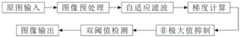
图1为本发明一种野外岩石结构面粗糙度的量测及计算方法流程图;1 is a flow chart of a method for measuring and calculating the roughness of a field rock structure surface according to the present invention;
图2为本发明摄影控制框架示意图;2 is a schematic diagram of a photography control frame of the present invention;
图3为本发明具体拍摄位置效果图;Fig. 3 is the effect diagram of concrete shooting position of the present invention;
图4为本发明一组结构面多视点拍摄实物图;Fig. 4 is a group of structural planes of the present invention photographed from multiple viewpoints;
图5为本发明结构面的三维点云模型图;Fig. 5 is the three-dimensional point cloud model diagram of the structure surface of the present invention;
图6为本发明Canny算子改进流程图;Fig. 6 is the improved flow chart of Canny operator of the present invention;
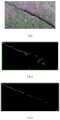
图7为本发明提取裂隙的效果对比图,其中a为结构面示意图,b为Canny算法计算效果图,c为改进后Canny计算效果图;7 is a comparison diagram of the effect of extracting cracks according to the present invention, wherein a is a schematic diagram of a structural plane, b is a calculation effect diagram of Canny algorithm, and c is an improved Canny calculation effect diagram;
图8为本发明提取的不同方向的粗糙度轮廓曲线图;Fig. 8 is the roughness profile curves of different directions extracted by the present invention;
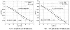
图9为本发明拟合的不同方向的分形维数示意图,其中a为0度轮廓线分形维数拟合值,b为165度轮廓线分形维数拟合值;9 is a schematic diagram of the fractal dimension in different directions fitted by the present invention, wherein a is the fitting value of the fractal dimension of the 0-degree contour line, and b is the fitting value of the fractal dimension of the 165-degree contour line;
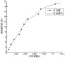
图10为标准粗糙度曲线JRC与分形维数D关系图;Figure 10 is a graph showing the relationship between the standard roughness curve JRC and the fractal dimension D;
附图中标记说明:1—结构面,2—摄影控制框架,3—待测区域结构面,4—标签纸(控制点),P1—拍摄点1(结构面左起45°拍摄点),P2—拍摄点2(正对结构面拍摄点),P3—拍摄点3(结构面上方45°拍摄点),P5—拍摄点5(结构面下方45°拍摄点),P4—拍摄点4(结构面右起45°拍摄点),Pn—拍摄点n(补测点)。Description of the symbols in the accompanying drawings: 1—structure plane, 2—photography control frame, 3—structure plane of the area to be measured, 4—label paper (control point), P1 —shooting point 1 (45° shooting point from the left of the structure plane) , P2—shooting point2 (shooting point facing the structural surface),P3 —shooting point 3 (shooting point 45° above the structural surface),P5 —shooting point5 (shooting point 45° below the structural surface), P4 - Shooting point 4 (45° shooting point from the right of the structure plane), Pn - Shooting point n (supplementary measurement point).
具体实施方式Detailed ways
下面结合附图和具体实施方式进一步说明本发明方案。The solution of the present invention is further described below with reference to the accompanying drawings and specific embodiments.
一种野外岩石结构面粗糙度的量测及计算方法,方法步骤包括:A method for measuring and calculating the roughness of a rock structure surface in the field, the method steps include:
步骤1、利用平直木条构建闭合的控制框架,所述控制框架的木条位于不同的平面,在木条贴上摄影测量标记点标签纸形成拍摄控制点和建模校准点;
步骤2、对控制框架进行校准,使其达到设定的精度要求;
步骤3、将校准后的控制框架固定在待测结构面上,选择不同的位置对待测结构面进行拍摄,拍摄范围包含整个框架;
步骤4、利用步骤3得到的照片,建立野外岩石结构面的三维点云模型;
步骤5、利用步骤4建立的三维点云模型提取结构面任一方向的粗糙度轮廓曲线;
步骤6、利用步骤5提取的结构面粗糙度轮廓曲线计算结构面粗糙度分形维数;
步骤7、利用步骤6得到的岩石结构面粗糙度分形维数,计算出对应的岩石结构面粗糙度系数。Step 7: Using the fractal dimension of the rock structure surface roughness obtained in
步骤1的控制框架为矩形,组成矩形控制框架的四根木条不在同一水平面,矩形控制框架上所贴的标签纸个数不少于7个。The control frame in
步骤3的拍摄位置至少为5个,包括在正对固定控制框架的结构面,以及以结构面为平面,以45°角为仰角或俯角的上下左右四个位置。There are at least 5 shooting positions in
步骤4建立野外岩石结构面的三维点云模型,具体步骤为:Step 4: Establish a three-dimensional point cloud model of the rock structure surface in the field. The specific steps are:
步骤4.1、进行SIFT特征匹配:采用SIFT算法对图像进行特征匹配,得到多视图之间的几何关系;Step 4.1, perform SIFT feature matching: use the SIFT algorithm to perform feature matching on the image to obtain the geometric relationship between multiple views;
步骤4.2、建立稀疏点云:对得到的几何关系采用光束法平差(BundleAdjustment)得出图像匹配点的坐标,建立稀疏点云;Step 4.2, establish a sparse point cloud: use the beam method adjustment (BundleAdjustment) to obtain the coordinates of the image matching points for the obtained geometric relationship, and establish a sparse point cloud;
步骤4.3、生成稠密三维点云,建立三维点云模型:首先根据建立的稀疏点云,由运动恢复结构(SFM)算法分析相机运动进而寻找三维点云结构;然后利用聚类的多视点立体视图(CMVS)对三维点云结构进行聚簇;最后采用基于面片模型的密集匹配(PMVS)对聚簇进行匹配、扩展、过滤完成密集匹配同时生成稠密三维点云,即得到野外岩石结构面的三维点云模型。Step 4.3. Generate a dense 3D point cloud and establish a 3D point cloud model: first, according to the established sparse point cloud, the motion recovery structure (SFM) algorithm is used to analyze the camera motion and then find the 3D point cloud structure; then use the clustered multi-view stereo view (CMVS) to cluster the 3D point cloud structure; finally, the dense matching based on the patch model (PMVS) is used to match, expand and filter the clusters to complete the dense matching and generate dense 3D point clouds, that is, the field rock structure surface is obtained. 3D point cloud model.
步骤5提取结构面任一方向的粗糙度轮廓曲线的具体步骤为:
步骤5.1、通过任一个平面A与重建的三维点云结构面模型进行垂直相交,提取与该平面在一定距离范围内的点云坐标;Step 5.1. Through any plane A, vertically intersect with the reconstructed 3D point cloud structure surface model, and extract the point cloud coordinates within a certain distance from the plane;
步骤5.2、将提取的点云坐标沿着平面A的法线方向,向平面A垂直投影得到投影点的二维坐标;Step 5.2, project the extracted point cloud coordinates along the normal direction of plane A to plane A to obtain the two-dimensional coordinates of the projected point;
步骤5.3、对得到的投影点采用线性插值法进行优化,将优化后的投影点连结即得该方向的结构面粗糙度曲线。Step 5.3: Use linear interpolation to optimize the obtained projection points, and connect the optimized projection points to obtain the roughness curve of the structure surface in this direction.
步骤6通过最小二乘法计算粗糙度分形维数。Step 6: Calculate the roughness fractal dimension by the least square method.
步骤7计算岩石结构面粗糙度系数的公式为:Step 7 The formula for calculating the roughness coefficient of the rock structure surface is:
JRC=2589814.091D3-7962029.588D2+8158190.255D-2785975.081JRC=2589814.091D3 -7962029.588D2 +8158190.255D-2785975.081
式中,D为结构面粗糙度分形维数,JRC为对应的岩石结构面粗糙度系数。where D is the fractal dimension of the structural surface roughness, and JRC is the corresponding roughness coefficient of the rock structural surface.
实施例1:Example 1:
本实施例以甘肃北山预选区花岗岩岩石结构面为研究对象,野外岩石结构面粗糙度的量测及计算方法,如图1所示,包括如下步骤:This embodiment takes the granite rock structure plane in the Beishan preselection area of Gansu as the research object. The measurement and calculation method of the roughness of the rock structure plane in the field, as shown in Figure 1, includes the following steps:
(1)构建近景摄影测量控制框架(1) Build a close-range photogrammetry control framework
首先用4根边长50cm的平直木条组成矩形的框架,然后在框架上表面粘贴7个摄影测量标记点标签纸组成控制框架,如图2所示,其中3根木条上贴各贴两个标签纸,另外一个仅贴一个标签纸,将组成后的控制框架在室内用三维激光扫描仪或全站仪进行标定和校准。First,
(2)对控制框架进行校准,使其达到设定的精度要求(2) Calibrate the control frame to make it meet the set accuracy requirements
对控制框架的标定和校准方法为现有方法,要求的精度为:各实测控制点坐标各分量值与模型上对应控制点的坐标分量值的最大误差绝对值不超过0.5mm,平均误差不超过0.25mm校准方法具体可参见参考文献:The calibration and calibration method of the control frame is the existing method, and the required accuracy is: the maximum absolute value of the absolute value of the error between each component value of the measured control point coordinates and the coordinate component value of the corresponding control point on the model does not exceed 0.5mm, and the average error does not exceed 0.5mm. For details on the 0.25mm calibration method, please refer to the references:
劳达宝,杨学友,邾继贵,等.扫描平面激光坐标测量系统校准方法的优化[J].光学精密工程,2011,19(4):870-877.Lau Dabao, Yang Xueyou, Zhu Jigui, et al. Optimization of Calibration Method for Scanning Plane Laser Coordinate Measuring System [J]. Optical Precision Engineering, 2011, 19(4): 870-877.
(3)对固定有控制框架的结构面进行拍摄(3) Photographing the structural surface with the control frame fixed
通过对控制框架标定后,将其用橡胶泥等暂时固定在野外待测的结构面上,以结构面为平面,以45°角为仰角或俯角分别在含控制框架结构面的上下左右四个位置以及正对结构面位置进行拍摄,具体拍摄位置效果图,如图3所示;拍摄后实物图,如图4所示。After calibrating the control frame, it is temporarily fixed on the structural surface to be measured in the field with rubber mud, etc., with the structural surface as the plane, and the 45° angle as the elevation angle or depression angle. The position and the position facing the structural surface are taken. The specific effect diagram of the shooting position is shown in Figure 3; the actual picture after shooting is shown in Figure 4.
(4)以摄取的照片为基础,建立结构面的三维点云模型(4) Based on the captured photos, establish a 3D point cloud model of the structural surface
首先导入拍摄实物图(图4),采用SIFT算法对图像进行特征匹配,得到多视图之间几何关系;其次通过对建立得到的几何关系采用光束法平差(Bundle Adjustment)得出图像匹配点的坐标,建立稀疏点云;再由运动恢复结构(SFM)算法分析相机运动进而寻找三维点云结构,利用聚类的多视点立体视图(CMVS)对图像进行聚簇;最后,采用基于面片模型的密集匹配(PMVS)通过匹配、扩展、过滤三个阶段来完成密集匹配同时生成稠密三维点云,以此建立野外岩石结构面的三维点云模型,如图5所示。First, import the real image (Fig. 4), and use the SIFT algorithm to match the features of the images to obtain the geometric relationship between the multiple views; secondly, the Bundle Adjustment of the established geometric relationship is used to obtain the matching points of the images. Then, the camera motion is analyzed by the motion recovery structure (SFM) algorithm to find the 3D point cloud structure, and the clustered multi-view stereo view (CMVS) is used to cluster the image. Finally, the patch-based model is used. The dense matching (PMVS) completes dense matching through three stages of matching, expansion, and filtering, and generates dense 3D point clouds, so as to establish a 3D point cloud model of the rock structure surface in the field, as shown in Figure 5.
(5)提取结构面粗糙度的轮廓曲线(5) Extract the profile curve of the roughness of the structural surface
基于建立的三维点云模型,对模型中任一方向的结构面粗糙度进行提取,以得到结构面粗糙度轮廓曲线,如图8所示,示出了0°和165°方向的粗糙度曲线。提取的具体过程如下:Based on the established 3D point cloud model, the roughness of the structural surface in any direction in the model is extracted to obtain the roughness profile curve of the structural surface, as shown in Figure 8, showing the roughness curves in the 0° and 165° directions . The specific process of extraction is as follows:
(5.1)通过一个具有一定宽度的平面A与重建的结构面进行垂直相交,提取相交部分的点云坐标,统计结构面信息。(5.1) A plane A with a certain width is vertically intersected with the reconstructed structural plane, and the point cloud coordinates of the intersecting part are extracted, and the structural plane information is counted.
(5.2)将提取的点云坐标沿着平面A的法线方向,向平面A垂直投影得到投影点的二维坐标,其中截面A的宽度越大,结构面表面轮廓线包含的点就越多,得到相应的轮廓线就越粗。(5.2) The two-dimensional coordinates of the projected point are obtained by vertically projecting the extracted point cloud coordinates along the normal direction of plane A to plane A. The larger the width of section A, the more points contained in the surface contour of the structural surface , the corresponding contour line is thicker.
(5.3)本实施例截取了10cm的有效长度进行研究,首先设置起点和终点的坐标,确定截线方向,其中截线宽度是截线由中心向两侧扩展d/2,d为截线宽度。然后将截线方向的结构面粗糙度曲线全部表示出来,横坐标为长度,纵坐标为z,为了方便计算,将横坐标整体右移,最左端为x=0。(5.3) In this example, an effective length of 10 cm is intercepted for research. First, the coordinates of the starting point and the end point are set, and the direction of the stub is determined, wherein the width of the stub is the d/2 that the stub expands from the center to both sides, and d is the width of the stub. . Then, all the roughness curves of the structural surface in the direction of the cross section are shown. The abscissa is the length and the ordinate is z. For the convenience of calculation, the abscissa is moved to the right, and the leftmost end is x=0.
(5.4)显示有效曲线图,将提取数据按照大小(从左往右)排列,二维坐标是点云坐标向截面的投影,若有多个点,则进行插值法得出最优点,用光滑曲线连结最优点即得结构面粗糙度轮廓曲线。(5.4) Display the effective curve graph, and arrange the extracted data according to the size (from left to right). The two-dimensional coordinates are the projection of the point cloud coordinates to the cross-section. The curve is connected to the optimal point to obtain the surface roughness profile curve.
(6)通过粗糙度曲线计算出相应的结构面分形维数D(6) Calculate the fractal dimension D of the corresponding structural surface through the roughness curve
本方法为现有方法,采用最小二乘法可拟合出结构面粗糙度量规法分形维数值D,本次实验拟合出相应结构面的分形维数为1.0046和1.0051,如图9所示,具体方法可参见参考文献:王建军,徐西鹏.花岗石抛光表面的粗糙度、分形维数及其关系研究[J].计量学报,2007,28(2):124-128.周创兵,熊文林.节理面粗糙度系数与分形维数的关系[J].武汉大学学报(工学版),1996(ws):1-5.This method is an existing method. The least squares method can be used to fit the fractal dimension value D of the roughness metric method of the structural surface. The fractal dimension of the corresponding structural surface is fitted to be 1.0046 and 1.0051 in this experiment, as shown in Figure 9. For specific methods, please refer to the references: Wang Jianjun, Xu Xipeng. Roughness, fractal dimension and their relationship of polished granite surfaces [J]. Journal of Metrology, 2007, 28(2): 124-128. Zhou Chuangbing, Xiong Wenlin. Joints The relationship between surface roughness coefficient and fractal dimension[J]. Journal of Wuhan University (Engineering Science Edition), 1996(ws): 1-5.
(7)计算结构面粗糙度系数JRC(7) Calculate the roughness coefficient JRC of the structural surface
将上一步计算得到的岩石结构面粗糙度分形维数D,代入下式Substitute the fractal dimension D of rock structure surface roughness calculated in the previous step into the following formula
JRC=2589814.091D3-7962029.588D2+8158190.255D-2785975.081JRC=2589814.091D3 -7962029.588D2 +8158190.255D-2785975.081
即可计算出不同方向上的岩石结构面粗糙度分形维数D对应的岩石结构面粗糙度系数JRC。The rock structure surface roughness coefficient JRC corresponding to the fractal dimension D of rock structure surface roughness in different directions can be calculated.
为了说明上述公式的可靠性,我们基于改进后的Canny算法(改进方法见图6,改进效果见图7)对Barton十条标准轮廓曲线进行提取,并对提取后的每条轮廓线按照量规法计算出其对应的分形维数D,应用最小二乘法对计算结果进行拟合,即得出JRC与D的关系,如图10所示,计算结果见表1,拟合结果符合粗糙度等级越大,分形维数值越大的客观规律。In order to illustrate the reliability of the above formula, we extracted ten standard contour curves of Barton based on the improved Canny algorithm (see Fig. 6 for the improved method and Fig. 7 for the improvement effect), and calculated each contour line after extraction according to the gauge method. The corresponding fractal dimension D is obtained, and the least squares method is used to fit the calculation results, that is, the relationship between JRC and D is obtained, as shown in Figure 10. The calculation results are shown in Table 1. The fitting results conform to the larger the roughness grade. , the objective law that the larger the fractal dimension value is.
表1标准曲线分形维数计算结果Table 1 Calculation results of fractal dimension of standard curve

Claims (6)
Translated fromChinesePriority Applications (1)
| Application Number | Priority Date | Filing Date | Title |
|---|---|---|---|
| CN201710802102.9ACN107655459B (en) | 2017-09-07 | 2017-09-07 | A method for measuring and calculating the roughness of rock structures in the field |
Applications Claiming Priority (1)
| Application Number | Priority Date | Filing Date | Title |
|---|---|---|---|
| CN201710802102.9ACN107655459B (en) | 2017-09-07 | 2017-09-07 | A method for measuring and calculating the roughness of rock structures in the field |
Publications (2)
| Publication Number | Publication Date |
|---|---|
| CN107655459A CN107655459A (en) | 2018-02-02 |
| CN107655459Btrue CN107655459B (en) | 2020-11-27 |
Family
ID=61129239
Family Applications (1)
| Application Number | Title | Priority Date | Filing Date |
|---|---|---|---|
| CN201710802102.9AActiveCN107655459B (en) | 2017-09-07 | 2017-09-07 | A method for measuring and calculating the roughness of rock structures in the field |
Country Status (1)
| Country | Link |
|---|---|
| CN (1) | CN107655459B (en) |
Families Citing this family (10)
| Publication number | Priority date | Publication date | Assignee | Title |
|---|---|---|---|---|
| CN106097436B (en)* | 2016-06-12 | 2019-06-25 | 广西大学 | A kind of three-dimensional rebuilding method of large scene object |
| CN109389596B (en)* | 2018-10-12 | 2022-04-12 | 深圳大学 | A method for evaluating the overall roughness of three-dimensional irregular particle surfaces |
| CN109540104A (en)* | 2018-11-30 | 2019-03-29 | 广西玉林华飞网络科技有限公司 | A kind of UAV system being used for highway administration using photogrammetric technology |
| CN109859301A (en)* | 2019-03-04 | 2019-06-07 | 浙江大学 | A kind of rock structural face roughness value fining characterizing method |
| CN111507194B (en)* | 2020-03-20 | 2022-07-22 | 东华理工大学 | Ground-based LiDAR branch and leaf point cloud separation method based on fractal dimension supervised learning |
| CN111998833B (en)* | 2020-09-02 | 2022-10-18 | 中国科学院西北生态环境资源研究院 | A measuring device, measuring method and surface roughness measuring method |
| CN113776469A (en)* | 2021-08-10 | 2021-12-10 | 同济大学 | Method and system for detecting surface roughness of powder particles |
| CN113920081A (en)* | 2021-09-30 | 2022-01-11 | 杭州电子科技大学 | A kind of tool wear detection method |
| CN117173425B (en)* | 2023-11-02 | 2024-01-30 | 东华理工大学南昌校区 | Intelligent extraction method and system for roughness of rock structural surface |
| CN118212595B (en)* | 2024-05-21 | 2024-07-19 | 四川凉山水洛河电力开发有限公司 | Monitoring method for landslide and slump stones on side slope |
Citations (3)
| Publication number | Priority date | Publication date | Assignee | Title |
|---|---|---|---|---|
| CN102538770A (en)* | 2012-01-17 | 2012-07-04 | 中国电力工程顾问集团中南电力设计院 | Low altitude photography image control point arranging method |
| CN102721409A (en)* | 2012-05-29 | 2012-10-10 | 东南大学 | Measuring method of three-dimensional movement track of moving vehicle based on vehicle body control point |
| CN103926156A (en)* | 2014-04-10 | 2014-07-16 | 内蒙古科技大学 | Multi-fractal evaluation method for three-dimensional rock structure surface shear mechanical behavior |
Family Cites Families (13)
| Publication number | Priority date | Publication date | Assignee | Title |
|---|---|---|---|---|
| DE4218382A1 (en)* | 1992-06-04 | 1993-12-09 | Leonhardt Klaus Prof Dr Ing Ha | Optical profilometer for surface roughness measurement with adaptive inclination adjustment and new type of detection system - has control system maintaining beam perpendicular to measurement surface, uses interferometric heterodyne detection |
| CN1779415A (en)* | 2004-11-18 | 2006-05-31 | 金华职业技术学院 | Measuring Method of Roughness Coefficient of Rock Mass Structural Surface |
| CN1253692C (en)* | 2004-12-15 | 2006-04-26 | 金华职业技术学院 | Method for determining dimensional size effects of toughness coefficients of typical stone structural surface |
| CN101055175A (en)* | 2007-04-30 | 2007-10-17 | 浙江建设职业技术学院 | Simple measurement method for rock structural plane roughness coefficient |
| DE102011014779A1 (en)* | 2011-03-15 | 2012-09-20 | Fraunhofer-Gesellschaft zur Förderung der angewandten Forschung e.V. | Device and method for measuring an object |
| JP2014516409A (en)* | 2011-04-15 | 2014-07-10 | ファロ テクノロジーズ インコーポレーテッド | Improved position detector for laser trackers. |
| CN103278113B (en)* | 2013-02-27 | 2015-09-30 | 中国林业科学研究院木材工业研究所 | A kind of method of contactless Fast Measurement Wood Surface Roughness |
| US9404754B2 (en)* | 2013-03-25 | 2016-08-02 | Raytheon Company | Autonomous range-only terrain aided navigation |
| CN104697476B (en)* | 2015-03-19 | 2017-06-06 | 北京时代之峰科技有限公司 | Roughness light cuts the automatic testing method and device of contour curve |
| CN105023291A (en)* | 2015-05-22 | 2015-11-04 | 燕山大学 | Criminal scene reconstructing apparatus and method based on stereoscopic vision |
| CN105139441A (en)* | 2015-07-10 | 2015-12-09 | 中国人民解放军装甲兵工程学院 | Fractal dimension obtaining method of coating surface morphology |
| CN106227923B (en)* | 2016-07-14 | 2018-02-27 | 中国地质大学(武汉) | A kind of rock mass discontinuity three-dimensional roughness evaluation method |
| CN106989731B (en)* | 2017-03-30 | 2019-12-10 | 中国科学院遥感与数字地球研究所 | Close-range photogrammetry method for observing surface roughness |
- 2017
- 2017-09-07CNCN201710802102.9Apatent/CN107655459B/enactiveActive
Patent Citations (3)
| Publication number | Priority date | Publication date | Assignee | Title |
|---|---|---|---|---|
| CN102538770A (en)* | 2012-01-17 | 2012-07-04 | 中国电力工程顾问集团中南电力设计院 | Low altitude photography image control point arranging method |
| CN102721409A (en)* | 2012-05-29 | 2012-10-10 | 东南大学 | Measuring method of three-dimensional movement track of moving vehicle based on vehicle body control point |
| CN103926156A (en)* | 2014-04-10 | 2014-07-16 | 内蒙古科技大学 | Multi-fractal evaluation method for three-dimensional rock structure surface shear mechanical behavior |
Also Published As
| Publication number | Publication date |
|---|---|
| CN107655459A (en) | 2018-02-02 |
Similar Documents
| Publication | Publication Date | Title |
|---|---|---|
| CN107655459B (en) | A method for measuring and calculating the roughness of rock structures in the field | |
| Arias et al. | Digital photogrammetry, GPR and computational analysis of structural damages in a mediaeval bridge | |
| Arias et al. | Control of structural problems in cultural heritage monuments using close-range photogrammetry and computer methods | |
| CN100557634C (en) | A camera calibration method based on dual one-dimensional targets | |
| CN106323176B (en) | A kind of three-dimensional displacement monitoring method of open-pit slope | |
| CN108458665A (en) | The method for carrying out the quick distortion measurement in tunnel using up short | |
| CN110285827A (en) | A distance-constrained photogrammetric high-precision target location method | |
| CN109900205B (en) | High-precision single-line laser and optical camera rapid calibration method | |
| CN101586943B (en) | Method for calibrating structure light vision transducer based on one-dimensional target drone | |
| CN106875467A (en) | D Urban model Rapid Updating | |
| CN103559708B (en) | Industrial fixed-focus camera parameter calibration device based on side's target model | |
| CN104240262A (en) | Camera external parameter calibration device and calibration method for photogrammetry | |
| CN107014338A (en) | A kind of component attitude measurement method and its application based on high speed camera | |
| CN101963500A (en) | Computer vision large-scale distance measuring method and portable distance measurer for applying same | |
| CN111402315A (en) | A three-dimensional distance measurement method for adaptively adjusting the baseline of a binocular camera | |
| CN104697463A (en) | Blanking feature constraining calibrating method and device for binocular vision sensor | |
| CN103697811B (en) | A kind of camera is combined the method obtaining contour of object three-dimensional coordinate with structure light source | |
| CN107687821B (en) | Calibration method of multi-camera light knife system for shape measurement of deep hole rotating parts | |
| CN101908228B (en) | Digital building measuring and drawing method for acquiring building vertical face map | |
| CN107504959B (en) | Method for measuring house wall base outline by utilizing inclined aerial image | |
| CN1405736A (en) | EEG electrode space positioning method based on up shot measure | |
| CN118031854A (en) | Automatic rock structural surface roughness extraction method based on Bin-sfm photogrammetry technology | |
| CN101038156A (en) | Portable measuring system for surface three-dimensional appearance of rock | |
| CN208061260U (en) | A kind of line-scan digital camera caliberating device for stereo-visiuon measurement | |
| CN204301746U (en) | A kind of three-dimensional calibration device based on orienting reflex ball |
Legal Events
| Date | Code | Title | Description |
|---|---|---|---|
| PB01 | Publication | ||
| PB01 | Publication | ||
| SE01 | Entry into force of request for substantive examination | ||
| SE01 | Entry into force of request for substantive examination | ||
| GR01 | Patent grant | ||
| GR01 | Patent grant |