CN107636409B - Refrigerator with a door - Google Patents
Refrigerator with a doorDownload PDFInfo
- Publication number
- CN107636409B CN107636409BCN201680034213.3ACN201680034213ACN107636409BCN 107636409 BCN107636409 BCN 107636409BCN 201680034213 ACN201680034213 ACN 201680034213ACN 107636409 BCN107636409 BCN 107636409B
- Authority
- CN
- China
- Prior art keywords
- cover
- engaging
- refrigerator
- chamber
- connector
- Prior art date
- Legal status (The legal status is an assumption and is not a legal conclusion. Google has not performed a legal analysis and makes no representation as to the accuracy of the status listed.)
- Expired - Fee Related
Links
Images


Classifications
- F—MECHANICAL ENGINEERING; LIGHTING; HEATING; WEAPONS; BLASTING
- F25—REFRIGERATION OR COOLING; COMBINED HEATING AND REFRIGERATION SYSTEMS; HEAT PUMP SYSTEMS; MANUFACTURE OR STORAGE OF ICE; LIQUEFACTION SOLIDIFICATION OF GASES
- F25D—REFRIGERATORS; COLD ROOMS; ICE-BOXES; COOLING OR FREEZING APPARATUS NOT OTHERWISE PROVIDED FOR
- F25D13/00—Stationary devices, e.g. cold-rooms
- F—MECHANICAL ENGINEERING; LIGHTING; HEATING; WEAPONS; BLASTING
- F25—REFRIGERATION OR COOLING; COMBINED HEATING AND REFRIGERATION SYSTEMS; HEAT PUMP SYSTEMS; MANUFACTURE OR STORAGE OF ICE; LIQUEFACTION SOLIDIFICATION OF GASES
- F25D—REFRIGERATORS; COLD ROOMS; ICE-BOXES; COOLING OR FREEZING APPARATUS NOT OTHERWISE PROVIDED FOR
- F25D23/00—General constructional features
- F—MECHANICAL ENGINEERING; LIGHTING; HEATING; WEAPONS; BLASTING
- F25—REFRIGERATION OR COOLING; COMBINED HEATING AND REFRIGERATION SYSTEMS; HEAT PUMP SYSTEMS; MANUFACTURE OR STORAGE OF ICE; LIQUEFACTION SOLIDIFICATION OF GASES
- F25D—REFRIGERATORS; COLD ROOMS; ICE-BOXES; COOLING OR FREEZING APPARATUS NOT OTHERWISE PROVIDED FOR
- F25D17/00—Arrangements for circulating cooling fluids; Arrangements for circulating gas, e.g. air, within refrigerated spaces
- F25D17/04—Arrangements for circulating cooling fluids; Arrangements for circulating gas, e.g. air, within refrigerated spaces for circulating air, e.g. by convection
- F—MECHANICAL ENGINEERING; LIGHTING; HEATING; WEAPONS; BLASTING
- F25—REFRIGERATION OR COOLING; COMBINED HEATING AND REFRIGERATION SYSTEMS; HEAT PUMP SYSTEMS; MANUFACTURE OR STORAGE OF ICE; LIQUEFACTION SOLIDIFICATION OF GASES
- F25D—REFRIGERATORS; COLD ROOMS; ICE-BOXES; COOLING OR FREEZING APPARATUS NOT OTHERWISE PROVIDED FOR
- F25D23/00—General constructional features
- F25D23/06—Walls
- F—MECHANICAL ENGINEERING; LIGHTING; HEATING; WEAPONS; BLASTING
- F25—REFRIGERATION OR COOLING; COMBINED HEATING AND REFRIGERATION SYSTEMS; HEAT PUMP SYSTEMS; MANUFACTURE OR STORAGE OF ICE; LIQUEFACTION SOLIDIFICATION OF GASES
- F25D—REFRIGERATORS; COLD ROOMS; ICE-BOXES; COOLING OR FREEZING APPARATUS NOT OTHERWISE PROVIDED FOR
- F25D27/00—Lighting arrangements
- F—MECHANICAL ENGINEERING; LIGHTING; HEATING; WEAPONS; BLASTING
- F25—REFRIGERATION OR COOLING; COMBINED HEATING AND REFRIGERATION SYSTEMS; HEAT PUMP SYSTEMS; MANUFACTURE OR STORAGE OF ICE; LIQUEFACTION SOLIDIFICATION OF GASES
- F25D—REFRIGERATORS; COLD ROOMS; ICE-BOXES; COOLING OR FREEZING APPARATUS NOT OTHERWISE PROVIDED FOR
- F25D29/00—Arrangement or mounting of control or safety devices
Landscapes
- Engineering & Computer Science (AREA)
- Chemical & Material Sciences (AREA)
- Combustion & Propulsion (AREA)
- Physics & Mathematics (AREA)
- Mechanical Engineering (AREA)
- Thermal Sciences (AREA)
- General Engineering & Computer Science (AREA)
- Devices That Are Associated With Refrigeration Equipment (AREA)
- Cold Air Circulating Systems And Constructional Details In Refrigerators (AREA)
Abstract
Description
Translated fromChinese技术领域technical field
本发明涉及冷藏库。尤其涉及冷藏库主体侧引线与设置于冷藏库主体内各处的各种部件的部件侧引线的连接部的结构。The present invention relates to a refrigerator. In particular, it relates to the structure of the connection part of a refrigerator main body side lead wire and the component side lead wire of various components provided in various parts in a refrigerator main body.
背景技术Background technique
一般而言,冷藏库在冷藏库主体内具有冷藏室、蔬菜室和冷冻室等贮藏室。在这些贮藏室的一部分的室中设置有温度传感器。此外,在向冷藏室和蔬菜室供给冷气的管道中设置有风门等。关于温度传感器和风门等,冷藏库主体背面壁中的引线从背面壁等引出并与温度传感器和风门等连接,该主体引线与温度传感器和风门等的部件引线的连接部利用盖被遮盖(例如参照专利文献1)。Generally, a refrigerator has storage compartments, such as a refrigerator compartment, a vegetable compartment, and a freezer compartment, in a refrigerator main body. Temperature sensors are provided in some of these storage compartments. Moreover, dampers etc. are provided in the duct which supplies cool air to a refrigerator compartment and a vegetable compartment. With regard to the temperature sensor and the damper, etc., the lead wires in the rear wall of the refrigerator main body are drawn out from the rear wall and the like and connected to the temperature sensor, the damper, etc., and the connection portion of the lead wire of the main body and the lead wires of the components such as the temperature sensor and the damper is covered with a cover (for example, Refer to Patent Document 1).
图13A~图13C表示有专利文献1记载的冷藏库。在图13A~图13C所示的冷藏库100中,在蔬菜室101设置有加热器102,加热器102的引线103与从冷藏库主体104的背面壁引出的主体引线105连接。主体引线105与加热器引线103的连接,在凹设于蔬菜室背面的收纳部106内进行。此外,主体引线105与加热器引线103的连接器连接部分被连接器盖107覆盖,连接器盖107利用螺钉108安装固定于蔬菜室背面壁。13A to 13C show the refrigerator described in
如上述构成的冷藏库100因主体引线105与加热器引线103的拆装能够从蔬菜室101内进行,所以具有加热器102的维护性优良的优点。The
然而,覆盖连接器连接部的连接器盖107由螺钉108安装固定,因此具有连接器盖107的拆装麻烦,使得之不易的高维护性降低的问题。However, since the
特别是,螺钉紧固位于蔬菜室101的深处的位置,加之连接器盖107为了不显眼而设置于蔬菜室顶面附近,所以螺钉紧固部设置于蔬菜室顶面附近。因此,存在受蔬菜室101的顶面壁和侧壁妨碍螺钉紧固操作费事,维护性大幅降低的问题。In particular, the screw-fastening portion is provided in the deep portion of the
现有技术文献prior art literature
专利文献Patent Literature
专利文献1:日本特开平10-205984号公报Patent Document 1: Japanese Patent Application Laid-Open No. 10-205984
发明内容SUMMARY OF THE INVENTION
本发明是鉴于上述问题完成的,提供一种覆盖引线连接部的盖容易拆装的冷藏库。The present invention has been made in view of the above-mentioned problems, and provides a refrigerator in which the cover covering the lead wire connecting portion can be easily attached and detached.
具体而言,根据本发明的实施方式的一个例子的冷藏库设置有开口部面向贮藏室的连接器收纳室,在连接器收纳室的至少两处设置有卡合部,并且具有覆盖连接器收纳室的开口的盖。此外,根据本发明的实施方式的一个例子的冷藏库构成为与连接器收纳室的卡合部对应地在盖设置有卡止部,盖的卡止部卡合于连接器收纳室的卡合部从而连接器收纳室的开口部被盖覆盖。进一步,在卡合部与卡止部的卡合部分中的一个啮合有止动部件。Specifically, a refrigerator according to an example of an embodiment of the present invention is provided with a connector storage compartment with an opening facing the storage compartment, an engaging portion is provided at at least two places in the connector storage compartment, and the connector storage compartment is covered. cover of the opening of the chamber. In addition, the refrigerator according to an example of the embodiment of the present invention is configured such that the cover is provided with the engaging portion corresponding to the engaging portion of the connector accommodating chamber, and the engaging portion of the cover is engaged with the engaging portion of the connector accommodating chamber. so that the opening of the connector housing chamber is covered with the cover. Further, a stopper member is engaged with one of the engaging portion of the engaging portion and the engaging portion of the engaging portion.
根据这样的结构,通过仅在盖的卡止部嵌入连接器收纳室的卡合部的同时,在卡合部压入止动部件的简单的操作就能够将盖安装于连接器收纳室的开口。并且,利用啮合于盖的卡止部与连接器收纳室的卡合部的卡合部分的止动部件能够防止盖的意外的脱开。由此,与螺钉紧固相同,覆盖连接器收纳室的开口部的盖能够牢固地被固定保持,能够确实可靠地保护连接器连接部。According to such a configuration, the cover can be attached to the opening of the connector accommodating chamber by a simple operation of pressing the stopper member into the engaging portion only while the engaging portion of the lid is fitted into the engaging portion of the connector accommodating chamber. . In addition, accidental disengagement of the cover can be prevented by the stopper member engaged with the engaging portion of the engaging portion of the cover and the engaging portion of the connector housing chamber. Thereby, similarly to screw tightening, the cover covering the opening of the connector housing chamber can be firmly fixed and held, and the connector connecting portion can be reliably protected.
此外,根据本发明的实施方式的一个例子的冷藏库也可以与用于啮合止动部件侧的卡止部相邻地在盖设置防脱开用孔部,并且止动部件具有插入防脱开用孔部来进行限制以使得盖的卡止部不从连接器收纳室的卡合部脱开的防脱开部。Further, in the refrigerator according to an example of the embodiment of the present invention, the cover may be provided with a disengagement prevention hole portion adjacent to the latching portion for engaging the stopper member side, and the stopper member may have an insertion and disengagement prevention hole portion. A disengagement preventing portion that is restricted by the hole portion so that the engaging portion of the cover does not disengage from the engaging portion of the connector accommodating chamber.
根据这样的结构,盖的卡止部不会从卡合部脱开,能够确实地维持卡止状态。由此,在盖不会意外地脱开而牢固地被固定保持的同时,设置有盖的防脱开用孔部侧的卡止部能够形成为卡合力较弱的形状,因此,盖的卡止部能够以较轻的力于连接器收纳室的卡合部进行安装或拆卸,进而能够大幅提高盖拆装的操作性。According to such a configuration, the locking portion of the cover is not disengaged from the engaging portion, and the locked state can be surely maintained. Thereby, while the cover is firmly fixed and held without being accidentally disengaged, the latching portion on the side of the disengagement preventing hole portion provided with the cover can be formed in a shape with a weak engagement force. The stop portion can be attached to or detached from the engaging portion of the connector housing chamber with a relatively light force, thereby greatly improving the operability of attaching and detaching the cover.
此外,根据本发明的实施方式的一个例子的冷藏库也可以在连接器收纳室的成为贮藏室背面侧的后部设置有转动支点支承部,对应转动支点支承部在盖设置转动支点部。此外,盖也可以构成为将转动支点部嵌合于连接器收纳室的转动支点支承部,跟前侧部分向连接器收纳室侧转动,从而盖的卡止部卡合于连接器收纳室的卡合部。In addition, the refrigerator according to an example of the embodiment of the present invention may be provided with a pivot support portion in the rear portion of the connector storage compartment serving as the rear side of the storage compartment, and the cover may be provided with a pivot support portion corresponding to the pivot support portion. In addition, the cover may be configured such that the rotation fulcrum part is fitted into the rotation fulcrum support part of the connector housing chamber, and the front side part is rotated toward the connector housing chamber side so that the locking part of the cover is engaged with the latch of the connector housing chamber. Combined.
根据这样的结构,能够不进行盖的卡止部与连接器收纳室的卡合部的位置对准而将转动支点部嵌合于连接器收纳室的转动支点支承部,仅向连接器收纳室侧转动过去就安装盖,能够使盖的安装操作性产生飞跃性的提高。According to such a configuration, it is possible to fit the fulcrum portion to the fulcrum support portion of the connector accommodating chamber without aligning the locking portion of the cover and the engaging portion of the connector accommodating chamber, and only to the connector accommodating chamber. The cover can be mounted by turning it sideways, and the workability of mounting the cover can be dramatically improved.
此外,根据本发明的实施方式的一个例子的冷藏库也可以设置为连接器收纳室在以插入冷气管道的突出部的方式抵接于贮藏室背面地设置的搁板的后部上表面开口。此外,也可以构成为安装于连接器收纳室的开口部的盖的上方被与搁板的上表面构成实质上为同一个面的装饰盖覆盖。In addition, the refrigerator according to an example of the embodiment of the present invention may be provided such that the connector storage compartment is open to the rear upper surface of the shelf provided in contact with the rear surface of the storage compartment so as to insert the protrusion of the cold air duct. In addition, the upper surface of the cover attached to the opening of the connector housing chamber may be covered with a decorative cover which is formed to be substantially the same surface as the upper surface of the shelf.
根据这样的结构,连接器收纳室在能够利用冷气管道的突出部的侧方的空间(Space)不向贮藏室内突出而进行设置的同时,开口部利用与搁板上表面构成实质上为同一个面的装饰盖被覆盖,因此,能够使连接器收纳室的开口部不显眼,进而能够提高贮藏室内面的美观度。According to such a configuration, the connector storage chamber can be installed without protruding into the storage chamber using the space (Space) on the side of the protruding portion of the cold air duct, and the opening portion is substantially the same as the upper surface of the shelf. Since the decorative cover of the surface is covered, the opening of the connector storage chamber can be made inconspicuous, and the appearance of the interior of the storage chamber can be improved.
此外,根据本发明的实施方式的一个例子的冷藏库也可以构成为连接器收纳室的各卡合部与盖的各卡止部设置于在冷气管道的侧方方向远离贮藏室背面壁的跟前侧部分,并且,止动部件啮合于远离冷气管道侧的卡合部与卡止部的卡合部分。In addition, the refrigerator according to an example of the embodiment of the present invention may be configured such that each engaging portion of the connector storage compartment and each engaging portion of the cover are provided in front of the rear wall of the storage compartment in the lateral direction of the cold air duct The side part, and the stop member is engaged with the engaging part on the side away from the cold air duct and the engaging part of the engaging part.
根据这样的结构,止动部件能够不被冷气管道的突出壁面和贮藏室背面壁妨碍而进行拆装,能够进一步提高盖拆装的操作性。According to such a configuration, the stopper member can be attached and detached without being hindered by the protruding wall surface of the cold air duct and the rear wall of the storage compartment, and the workability of attaching and detaching the cover can be further improved.
此外,根据本发明的实施方式的一个例子的冷藏库也可以构成为在止动部件具有使止动部件自身固定于盖的棒状的止动件卡止部的同时,在止动件卡止部的卡止部分侧面具有倾斜面。In addition, the refrigerator according to an example of the embodiment of the present invention may be configured such that the stopper member includes a rod-shaped stopper locking portion for fixing the stopper member itself to the cover, and the stopper locking portion The side of the locking part has an inclined surface.
根据这样的结构,止动部件能够通过沿着止动件卡止部的倾斜面插入尺子或者一字螺丝刀等而使止动件卡止部向脱开方向变形进而从盖取下,止动部件亦能够容易地取下,能够提高操作性。According to such a configuration, the stopper member can be removed from the cover by inserting a ruler, a flat-blade screwdriver, or the like along the inclined surface of the stopper locking portion to deform the stopper locking portion in the disengagement direction, and the stopper member can be removed from the cover. It can also be removed easily, and the operability can be improved.
附图说明Description of drawings
图1是本发明的实施方式的冷藏库的主视图。Fig. 1 is a front view of the refrigerator according to the embodiment of the present invention.
图2是本发明的实施方式的冷藏库的门打开时的主视图。Fig. 2 is a front view when the door of the refrigerator according to the embodiment of the present invention is opened.
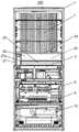
图3是本发明的实施方式的冷藏库的纵截面图。Fig. 3 is a longitudinal sectional view of the refrigerator according to the embodiment of the present invention.
图4是表示本发明的实施方式的冷藏库的引线连接部分的外观立体图。4 is an external perspective view showing a lead wire connection portion of the refrigerator according to the embodiment of the present invention.
图5是表示本发明的实施方式的冷藏库的引线连接部分的分解立体图。5 is an exploded perspective view showing a lead wire connection portion of the refrigerator according to the embodiment of the present invention.
图6是表示本发明的实施方式的冷藏库的引线连接部分的俯视图。6 is a plan view showing a lead wire connection portion of the refrigerator according to the embodiment of the present invention.
图7是表示本发明的实施方式的冷藏库的引线连接部分的放大立体图。7 is an enlarged perspective view showing a lead wire connection portion of the refrigerator according to the embodiment of the present invention.
图8是表示本发明的实施方式的冷藏库的引线连接部分的放大截面图。8 is an enlarged cross-sectional view showing a lead wire connection portion of the refrigerator according to the embodiment of the present invention.
图9是表示本发明的实施方式的冷藏库的引线连接部分中的引线收纳室、盖和止动部件的分解视图。9 is an exploded view showing a lead wire storage chamber, a cover, and a stopper member in a lead wire connecting portion of the refrigerator according to the embodiment of the present invention.
图10是表示本发明的实施方式的冷藏库的引线连接部分中的引线收纳室和盖的分解立体图。10 is an exploded perspective view showing a lead wire storage chamber and a cover in a lead wire connection portion of the refrigerator according to the embodiment of the present invention.
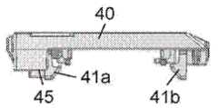
图11A是本发明的实施方式的冷藏库的覆盖引线连接部分的盖的立体图。11A is a perspective view of a cover covering a lead wire connection portion of the refrigerator according to the embodiment of the present invention.
图11B是从下方观察本发明的实施方式的冷藏库的覆盖引线连接部分的盖时的立体图。11B is a perspective view of the lid covering the lead wire connection portion of the refrigerator according to the embodiment of the present invention, when viewed from below.
图11C是本发明的实施方式的冷藏库的盖的侧视图。11C is a side view of the lid of the refrigerator according to the embodiment of the present invention.
图11D是本发明的实施方式的冷藏库的盖的俯视图。11D is a plan view of the lid of the refrigerator according to the embodiment of the present invention.
图12A是本发明的实施方式的冷藏库的覆盖引线连接部分的止动部件的立体图。12A is a perspective view of a stopper member covering a lead wire connection portion of the refrigerator according to the embodiment of the present invention.
图12B是从下方观察本发明的实施方式的冷藏库的止动部件的立体图。12B is a perspective view of the stopper member of the refrigerator according to the embodiment of the present invention as viewed from below.
图13A是表示现有的冷藏库的内部的主视图。Fig. 13A is a front view showing the inside of a conventional refrigerator.
图13B是现有的冷藏库的引线连接部分的截面图。13B is a cross-sectional view of a lead connection portion of a conventional refrigerator.
图13C是现有的冷藏库的引线连接部分的主视图。Fig. 13C is a front view of a lead wire connection portion of a conventional refrigerator.
具体实施方式Detailed ways
以下参照附图对本发明的实施方式的一个例子进行说明。不过,本发明并不被该实施方式限定。An example of an embodiment of the present invention will be described below with reference to the drawings. However, the present invention is not limited to this embodiment.
(实施方式)(Embodiment)
图1~图11D、图12A和图12B表示本发明的实施方式的一个例子的冷藏库200。首先,使用图1~图3对冷藏库200的整体的结构进行说明。FIGS. 1-11D, FIG. 12A, and FIG. 12B show the
在图1~图3中,本实施方式的冷藏库200具有前方开口的冷藏库主体1。如图3所示,冷藏库主体1由主要使用钢板的外箱2、由ABS树脂等硬质树脂成型的内箱3、和在外箱2与内箱3之间填充的硬质发泡聚氨酯等发泡隔热材料4构成。In FIGS. 1-3, the
冷藏库主体1利用分隔板5、6、6a被划分为多个贮藏室,在冷藏库主体1的最上部设置有冷藏室7,在冷藏室7的下方设置有切换室8a和与之并排设置的制冰室8b,进一步在其下方设置有冷冻室9,和在最下部设置有蔬菜室10。各贮藏室的前面的开口部分利用门11a~11e能够开闭地被封闭。The refrigerator
在冷藏库主体1的上部后方区域设置有机械室14。在机械室14收纳有压缩机15和进行水分去除的干燥器等制冷循环的高压侧构成部件。A
此外,在冷藏库主体1的背面设置有生成冷气的冷却室16、使来自冷却室16的冷气向冷藏室7、冷冻室9和蔬菜室10等供给循环的冷气管道17。In addition, on the rear surface of the refrigerator
在冷却室16内配置有冷却器19,在冷却器19的上部配置有冷却风扇20。冷却风扇20使利用冷却器19冷却的冷气经由冷气管道17在冷藏室7、冷冻室9和蔬菜室10等强制循环,进而冷却各贮藏室。A cooler 19 is arranged in the cooling
在利用来自冷却室16的冷气而被冷却的冷藏室7设置有用于载置食材的多个搁板24,在最下部形成有低温贮藏室23。低温贮藏室23成为例如能够在冷却至约1℃的温度域的冰温保鲜(child)室或者冷却至约-3℃的微冻结温度域的部分冷冻(Partial)室之间转换的低温贮藏室。The
另外,低温贮藏室23也可以不是能够在冰温保鲜室或者部分冷冻室之间转换的低温贮藏室,而设计为作为冰温保鲜室或者部分冷冻室专用地使用的低温贮藏室。In addition, the
低温贮藏室23如图4~图6所示,其上表面由亦能够作为位于冷藏室7的最下层的搁板而被利用的搁板部件24分隔、侧面由与供水箱室27(参照图2)之间进行分隔的分隔板27a分隔而形成。此外,在低温贮藏室23的内部设置有抽拉自如的容器25,其前方通过抽拉容器25而利用以搁板部件24的前端部为中心转动而打开的门26被闭盖。As shown in FIGS. 4 to 6 , the low-
此外,低温贮藏室23在顶面部分设置有照明装置22,照明装置22的引线与来自冷藏库主体1的背面的主体引线连接。Moreover, the low
以下使用图4~图11D、图12A和图12B对引线的连接部的结构进行说明。Hereinafter, the structure of the connection part of a lead wire is demonstrated using FIGS. 4-11D, FIG. 12A, and FIG. 12B.
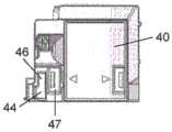
在图4~图11D、图12A和图12B中,收纳引线的连接器连接部的连接器收纳室30配置于冷气管道17的突出部17a侧方。连接器收纳室30的上面开口部31在搁板部件24的后部上表面开口。搁板部件24设置为以插入到冷气管道17的突出部17a的方式抵接于贮藏室背面。In FIGS. 4 to 11D , and FIGS. 12A and 12B , the
连接器收纳室30如图7所示,一体形成于构成冷气管道17的突出部17a的部件。此外,连接器收纳室30位于低温贮藏室23的后方,被搁板部件24的角部面24a遮盖,其上面开口部31的上方如图4所示,成为如下结构:利用与搁板部件24的上面构成实质上为同一个面的装饰盖32被覆盖。As shown in FIG. 7 , the
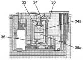
连接器收纳室30如图10所示,具有大致呈矩形框状的收纳空间33。在收纳空间33的后部壁面形成有来自冷藏库主体1的主体引线34(参照图6)所通过的凹处35。此外,在收纳空间33的前部壁面形成有从照明装置22通过搁板部件24中部而被引出的引线36(参照图6)所通过的凹处37。主体引线34的连接器34a和引线36的连接器36a(参照图6)以相互连接的状态被收纳于连接器收纳室30。As shown in FIG. 10 , the
在连接器收纳室30至少设置有两处卡合部38。在本实施方式中,在连接器收纳室30的收纳空间33的两侧设置有一对卡合部38。进一步,在连接器收纳室30,在成为低温贮藏室23的背面侧的后部两侧设置有转动支点支承部39。At least two
如图5所示,连接器收纳室30的上面开口部31安装有盖40进而覆盖连接器连接部分。As shown in FIG. 5 , a
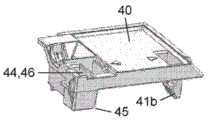
盖40如图11A~图11D所示,对应连接器收纳室30的卡合部38在跟前方侧部分设置有具有弹性的肋(Rib)状的卡止部41a、41b。盖40进一步对应转动支点支承部39在其后方部分设置有大致L字状的转动支点部43。As shown in FIGS. 11A to 11D , the
进一步,在盖40,与卡止部41a、41b中远离冷气管道17的突出部17a的一侧(图11A~图11D的左侧)的卡止部41a相邻设置有止动件插入部44(参照图11A),在止动件插入部44的下端缘设置有止动件用卡合部45。Further, in the
此外,在盖40,在靠近止动件插入部44的后方的部分与冷气管道17侧稍微错开的位置连接设置有防脱开用孔部46,与防脱开用孔部46相邻设置有引导用孔部47。In addition, the
在转动支点部43被嵌入于连接器收纳室30的转动支点支承部39的同时,卡止部41a、41a利用其弹力卡合于连接器收纳室30的卡合部38,从而盖40被安装于连接器收纳室30的上面开口部31。While the pivoting
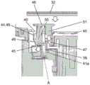
如图8所示,止动部件48被压入并插入到止动件插入部44,从而安装于连接器收纳室30的上面开口部31的盖40被固定于连接器收纳室30的上面开口部31。As shown in FIG. 8 , the
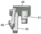
如图12A和图12B所示,在将盖40固定于连接器收纳室30的上面开口部31的止动部件48设置有具有弹性的棒状的止动件卡止部49,该止动件卡止部49插入到盖40的止动件插入部44并卡止于止动件用卡合部45。另外,止动件卡止部49如图12A所示,具有卡止部分侧的面倾斜的倾斜面49a。As shown in FIGS. 12A and 12B , the
此外,止动部件48在靠近止动件卡止部49的后方的部分与冷气管道17侧稍微错开的位置设置有棒状的防脱开部50。防脱开部50插入到盖40的防脱开用孔部46,沿着盖40的卡止部41a配置而限制卡止部41a、41b的移动。Further, the
进一步,在止动部件48设置有引导棒51,嵌合于盖40的引导用孔部47。Furthermore, guide
接着对如上所述构成的冷藏库200的作用效果进行说明。Next, the effects of the
在本实施方式中,以照明装置22的引线36与主体引线34连接的情况为示例。主体引线34与照明装置22的引线36的连接首先将从冷藏室7的背面壁引出的主体引线34与从搁板部件24引出的照明装置22的引线36在冷藏室7内连接。被连接的连接器连接部分与主体引线34和引线36多余的部分一同收纳于收纳空间33内,之后,在连接器收纳室30的上面开口部31安装盖40,进一步在其上方设置装饰盖32,主体引线34与引线36的连接工作完成。In this embodiment, the case where the
此处,覆盖引线连接部分的盖40仅卡止部41a、41b嵌入连接器收纳室30的卡合部38就能够安装于连接器收纳室30,能够以简单的操作在连接器收纳室30的上面开口部31安装固定盖40。Here, the
并且,在盖40的卡止部41a、41b与连接器收纳室30的卡合部38的卡合部分的一个,从盖40表面侧啮合有止动部件48,因此,不会发生卡止部41a与卡合部38的卡合意外脱开的情况。由此,与螺钉紧固相同,盖40能够牢固地被固定保持于连接器收纳室30的上面开口部31,进而能够确实保护连接器连接部分。In addition, since the
并且,本实施方式的止动部件48与和连接器收纳室30的卡合部38卡合的卡止部41a相邻地设置有防脱开部50,防脱开部50沿着盖40的卡止部41a配置而限制卡止部41a的移动。因此,盖40的卡止部41a无法向从卡合部38脱开的方向移动。因此,盖40不会发生卡止部41a从卡合部38意外地脱离的情况,所以能够确实地保持卡止状态,并被更牢固地被固定保持。In addition, the
此外,如上所述,利用防脱开部50卡止部41a的移动被限制,因此,设置有盖40的防脱开用孔部46的一侧的卡止部41a能够形成为卡合力比较弱的形状。因此,能够用较轻的力将盖40的卡止部41a于连接器收纳室30的卡合部38进行安装或拆卸,进而能够使盖40的拆装的操作性提高。In addition, as described above, the movement of the locking
此外,在本实施方式中,盖40仅将转动支点部43嵌合于连接器收纳室30的转动支点支承部39,并将盖40跟前侧部分向连接器收纳室30侧转动并推压就能够将盖40的卡止部41a、41b卡合于连接器收纳室30的卡合部38,从而将盖40安装于连接器收纳室30。In addition, in the present embodiment, the
因此,盖40不需要对盖40的卡止部41a、41b与连接器收纳室30的卡合部38进行位置对准等,能够提高盖40的安装的操作性。Therefore, the
并且,盖40于转动支点支承部39的嵌入和向连接器收纳室30侧的转动均能够向下进行,因此,与朝向顶面向上进行时相比,能够使盖40的安装操作性产生飞跃性地提高。Furthermore, since both the fitting of the
此外,止动部件48具有嵌合于盖40的引导用孔部47的引导棒51,因此,能够使利用防脱开部50更加确实可靠地防止卡止部41a的脱开。Moreover, since the
即,止动部件48通过将防脱开部50嵌合于盖40的防脱开用孔部46,沿着卡止部41a限制卡止部41a的移动进而进行脱开的防止,但此时,防脱开部50不断受到来自卡止部41a的图8的虚线箭头A所示方向的弹力而止动部件48整体倾斜。因此,力作用于卡止部41a的卡合脱开的方向。然而,嵌合于引导用孔部47的引导棒51通过与引导用孔部47的嵌合发挥阻止止动部件48整体的倾斜的作用。因此,不再发生止动部件48倾斜的情况,更加确实可靠利用防脱开部50防止卡止部41a脱开。That is, the
进一步,止动部件48在使止动部件48自身固定于盖40的止动件卡止部49的止动件卡止部分侧面具有倾斜面49a,所以能够容易地进行止动部件48的拆卸。即,从盖40的表面上方沿着止动件卡止部49的倾斜面49a在图12A的X所示的位置插入尺子或者一字螺丝刀等时,利用施加于倾斜面49a的分力,止动件卡止部49向与盖40的止动件用卡合部45的卡合脱开的方向移动。因此,止动部件48的拆卸变得容易。Furthermore, since the
此外,在本实施方式示例的连接器收纳室30设置于在低温贮藏室23的背面设置的冷气管道17的突出部17a的侧方,因此,能够不向低温贮藏室23内突出而进行设置。此外,还具有如下优点:能够在有效利用冷气管道17的突出部17a侧方的空间的同时,防止连接器收纳室30的突出。In addition, since the
此外,设置于覆盖连接器收纳室30的上面开口的盖40上方的装饰盖32与以插入冷气管道17的突出部17a的方式抵接于贮藏室背面而设置的搁板部件24的上表面构成实质上为的同一个面,因此,能够无形中提高冷藏室7内表面的美观度。In addition, the
进一步,连接器收纳室30的卡合部38与盖40的卡止部41a、41b设置于在冷气管道17的侧方方向远离贮藏室背面壁的跟前侧部分。此外,止动部件48构成为啮合于远离冷气管道17侧的卡合部38与卡止部41a的卡合部分。根据这样的结构,止动部件48能够不被冷气管道17的突出部17a的侧壁面和贮藏室背面壁妨碍而进行拆装,进而能够提高盖40的拆装的操作性。Further, the engaging
以上对本发明的实施方式的一个例子的冷藏库200进行了说明,但自不待言,本发明不限于此,能够在达成本发明的目的的范围内进行各种变更。即应该将上述实施方式考虑为是全部发明点的示例而非制限。换言之,本发明的范围不是通过上述实施方式中的说明而是通过权利要求表示,包括与权利要求等同的含义和范围内的全部变更。As mentioned above, although the
工业上的利用可能性Industrial use possibility
本发明提供一种可靠性高的冷藏库,其在连接器收纳室的盖能够容易地拆装的同时,盖能够牢固地被固定保持,进而能够在提高部件等的维护性的同时,能够使对引线连接器连接部的保护确实可靠。因此,家用自不必言,其还能够广泛地用于商用冷藏库和展示柜等多种用途。The present invention provides a highly reliable refrigerator in which the cover of the connector housing chamber can be easily detached and attached, and the cover can be firmly fixed and held, thereby improving the maintainability of components and the like, and making it possible to use The protection of the connection part of the lead connector is reliable. Therefore, it goes without saying that it can be widely used for various purposes such as commercial refrigerators and display cases.
符号说明Symbol Description
1 冷藏库主体1 The main body of the refrigerator
2 外箱2 outer boxes
3 内箱3 inner box
4 发泡隔热材料4 Foam insulation
5、6、6a 分隔板5, 6, 6a Separator
7 冷藏室7 Refrigerator
8a 切换室8a Switching Room
8b 制冰室8b Ice maker
9 冷冻室9 Freezer
10 蔬菜室10 Vegetable Room
11a~11e 门11a~11e Doors
14 机械室14 Mechanical Room
15 压缩机15 Compressor
16 冷却室16 Cooling Chamber
17 冷气管道17 Air-conditioning duct
17a 突出部17a Protrusion
19 冷却器19 Cooler
20 冷却风扇20 Cooling fan
22 照明装置22 Lighting device
23 低温贮藏室(贮藏室)23 Low temperature storage room (storage room)
24 搁板部件(搁板)24 Shelf parts (shelves)
25 容器25 containers
26 门26 doors
27 供水箱室27 Water supply tank room
27a 分隔板27a Divider
30 连接器收纳室30 Connector storage compartment
31 上面开口部31 Top opening
32 装饰盖32 Decorative cover
33 收纳空间33 Storage space
34 主体引线34 Body leads
34a 连接器34a connector
35 凹处35 recess
36 引线36 leads
36a 连接器36a connector
37 凹处37 recess
38 卡合部38 Engagement part
39 转动支点支承部39 Swivel fulcrum support
40 盖40 covers
41a、41b 卡止部41a, 41b Locking part
43 转动支点部43 Rotation fulcrum
44 止动件插入部44 Stopper insert
45 止动件用卡合部45 Engagement part for stopper
46 防脱开用孔部46 Hole for disengagement prevention
47 引导用孔部47 Guide hole
48 止动部件48 Stop parts
49 止动件卡止部49 Stopper locking part
49a 倾斜面49a Inclined surface
50 防脱开部50 Detachment prevention part
51 引导棒。51 Guide rod.
Claims (5)
Translated fromChinesePriority Applications (1)
| Application Number | Priority Date | Filing Date | Title |
|---|---|---|---|
| CN201911218950.0ACN111006436A (en) | 2015-06-18 | 2016-06-14 | Cold storage |
Applications Claiming Priority (3)
| Application Number | Priority Date | Filing Date | Title |
|---|---|---|---|
| JP2015122873AJP6617270B2 (en) | 2015-06-18 | 2015-06-18 | refrigerator |
| JP2015-122873 | 2015-06-18 | ||
| PCT/JP2016/002861WO2016203761A1 (en) | 2015-06-18 | 2016-06-14 | Refrigerator |
Related Child Applications (1)
| Application Number | Title | Priority Date | Filing Date |
|---|---|---|---|
| CN201911218950.0ADivisionCN111006436A (en) | 2015-06-18 | 2016-06-14 | Cold storage |
Publications (2)
| Publication Number | Publication Date |
|---|---|
| CN107636409A CN107636409A (en) | 2018-01-26 |
| CN107636409Btrue CN107636409B (en) | 2020-03-03 |
Family
ID=57545452
Family Applications (2)
| Application Number | Title | Priority Date | Filing Date |
|---|---|---|---|
| CN201680034213.3AExpired - Fee RelatedCN107636409B (en) | 2015-06-18 | 2016-06-14 | Refrigerator with a door |
| CN201911218950.0APendingCN111006436A (en) | 2015-06-18 | 2016-06-14 | Cold storage |
Family Applications After (1)
| Application Number | Title | Priority Date | Filing Date |
|---|---|---|---|
| CN201911218950.0APendingCN111006436A (en) | 2015-06-18 | 2016-06-14 | Cold storage |
Country Status (3)
| Country | Link |
|---|---|
| JP (1) | JP6617270B2 (en) |
| CN (2) | CN107636409B (en) |
| WO (1) | WO2016203761A1 (en) |
Families Citing this family (1)
| Publication number | Priority date | Publication date | Assignee | Title |
|---|---|---|---|---|
| CN113883797A (en)* | 2020-07-02 | 2022-01-04 | 日立环球生活方案株式会社 | Cold storage |
Citations (4)
| Publication number | Priority date | Publication date | Assignee | Title |
|---|---|---|---|---|
| JP2000274927A (en)* | 1999-01-21 | 2000-10-06 | Mitsubishi Electric Corp | Refrigerator and its manufacturing method |
| JP2000292053A (en)* | 1999-04-05 | 2000-10-20 | Mitsubishi Electric Corp | refrigerator |
| CN1341835A (en)* | 2000-09-04 | 2002-03-27 | 东芝株式会社 | Refrigerator |
| US20040182104A1 (en)* | 2003-03-20 | 2004-09-23 | Lg Electronics Inc. | Door for refrigerator |
Family Cites Families (6)
| Publication number | Priority date | Publication date | Assignee | Title |
|---|---|---|---|---|
| JP2538468Y2 (en)* | 1991-03-19 | 1997-06-18 | 三洋電機株式会社 | refrigerator |
| JPH08296953A (en)* | 1995-04-27 | 1996-11-12 | Toshiba Corp | refrigerator |
| CN1683872A (en)* | 2004-04-12 | 2005-10-19 | 乐金电子(天津)电器有限公司 | Insert door of refrigerator door |
| JP4934446B2 (en)* | 2007-01-31 | 2012-05-16 | 三洋電機株式会社 | Cooling storage |
| JP4861927B2 (en)* | 2007-08-02 | 2012-01-25 | 日立アプライアンス株式会社 | refrigerator |
| US20140145579A1 (en)* | 2012-11-27 | 2014-05-29 | Whirlpool Corporation | Modular interface for pantry temperature control |
- 2015
- 2015-06-18JPJP2015122873Apatent/JP6617270B2/enactiveActive
- 2016
- 2016-06-14WOPCT/JP2016/002861patent/WO2016203761A1/ennot_activeCeased
- 2016-06-14CNCN201680034213.3Apatent/CN107636409B/ennot_activeExpired - Fee Related
- 2016-06-14CNCN201911218950.0Apatent/CN111006436A/enactivePending
Patent Citations (4)
| Publication number | Priority date | Publication date | Assignee | Title |
|---|---|---|---|---|
| JP2000274927A (en)* | 1999-01-21 | 2000-10-06 | Mitsubishi Electric Corp | Refrigerator and its manufacturing method |
| JP2000292053A (en)* | 1999-04-05 | 2000-10-20 | Mitsubishi Electric Corp | refrigerator |
| CN1341835A (en)* | 2000-09-04 | 2002-03-27 | 东芝株式会社 | Refrigerator |
| US20040182104A1 (en)* | 2003-03-20 | 2004-09-23 | Lg Electronics Inc. | Door for refrigerator |
Also Published As
| Publication number | Publication date |
|---|---|
| JP6617270B2 (en) | 2019-12-11 |
| CN111006436A (en) | 2020-04-14 |
| JP2017009152A (en) | 2017-01-12 |
| WO2016203761A1 (en) | 2016-12-22 |
| CN107636409A (en) | 2018-01-26 |
Similar Documents
| Publication | Publication Date | Title |
|---|---|---|
| US10619911B2 (en) | Refrigerator | |
| US10415867B2 (en) | Refrigerator provided with ice maker and water supply unit | |
| KR102447914B1 (en) | refrigerator | |
| US8075072B2 (en) | Home bar and refrigerator including the home bar | |
| KR20060081919A (en) | Refrigerator | |
| KR20220079989A (en) | Door end closure assembly with integrated user interface | |
| US20190145694A1 (en) | Refrigerator | |
| RU2581735C2 (en) | Household refrigerator | |
| CN206556330U (en) | refrigerator | |
| CN107636409B (en) | Refrigerator with a door | |
| JP2016118313A (en) | refrigerator | |
| JP2019109032A (en) | Refrigerator and manufacturing method of the same | |
| JP6803530B2 (en) | refrigerator | |
| TWI570375B (en) | refrigerator | |
| JP6602733B2 (en) | refrigerator | |
| CN116324316A (en) | refrigerator | |
| JP6442705B2 (en) | refrigerator | |
| JP6386274B2 (en) | refrigerator | |
| JP7755983B2 (en) | Refrigerator and refrigerator manufacturing method | |
| JP5675905B2 (en) | refrigerator | |
| KR20220068119A (en) | Refrigerator | |
| JP7481854B2 (en) | refrigerator | |
| JP2014052141A (en) | refrigerator | |
| KR101988308B1 (en) | Refrigerator | |
| JP6466664B2 (en) | refrigerator |
Legal Events
| Date | Code | Title | Description |
|---|---|---|---|
| PB01 | Publication | ||
| PB01 | Publication | ||
| SE01 | Entry into force of request for substantive examination | ||
| SE01 | Entry into force of request for substantive examination | ||
| GR01 | Patent grant | ||
| GR01 | Patent grant | ||
| CF01 | Termination of patent right due to non-payment of annual fee | ||
| CF01 | Termination of patent right due to non-payment of annual fee | Granted publication date:20200303 |