CN107621729B - Backlight module and liquid crystal display using same - Google Patents
Backlight module and liquid crystal display using sameDownload PDFInfo
- Publication number
- CN107621729B CN107621729BCN201710889702.3ACN201710889702ACN107621729BCN 107621729 BCN107621729 BCN 107621729BCN 201710889702 ACN201710889702 ACN 201710889702ACN 107621729 BCN107621729 BCN 107621729B
- Authority
- CN
- China
- Prior art keywords
- light
- guide plate
- grating
- backlight module
- taking
- Prior art date
- Legal status (The legal status is an assumption and is not a legal conclusion. Google has not performed a legal analysis and makes no representation as to the accuracy of the status listed.)
- Expired - Fee Related
Links
Images


Classifications
- G—PHYSICS
- G02—OPTICS
- G02F—OPTICAL DEVICES OR ARRANGEMENTS FOR THE CONTROL OF LIGHT BY MODIFICATION OF THE OPTICAL PROPERTIES OF THE MEDIA OF THE ELEMENTS INVOLVED THEREIN; NON-LINEAR OPTICS; FREQUENCY-CHANGING OF LIGHT; OPTICAL LOGIC ELEMENTS; OPTICAL ANALOGUE/DIGITAL CONVERTERS
- G02F1/00—Devices or arrangements for the control of the intensity, colour, phase, polarisation or direction of light arriving from an independent light source, e.g. switching, gating or modulating; Non-linear optics
- G02F1/01—Devices or arrangements for the control of the intensity, colour, phase, polarisation or direction of light arriving from an independent light source, e.g. switching, gating or modulating; Non-linear optics for the control of the intensity, phase, polarisation or colour
- G02F1/13—Devices or arrangements for the control of the intensity, colour, phase, polarisation or direction of light arriving from an independent light source, e.g. switching, gating or modulating; Non-linear optics for the control of the intensity, phase, polarisation or colour based on liquid crystals, e.g. single liquid crystal display cells
- G02F1/133—Constructional arrangements; Operation of liquid crystal cells; Circuit arrangements
- G02F1/1333—Constructional arrangements; Manufacturing methods
- G02F1/1335—Structural association of cells with optical devices, e.g. polarisers or reflectors
- G02F1/1336—Illuminating devices
- G02F1/133615—Edge-illuminating devices, i.e. illuminating from the side
- G—PHYSICS
- G02—OPTICS
- G02B—OPTICAL ELEMENTS, SYSTEMS OR APPARATUS
- G02B6/00—Light guides; Structural details of arrangements comprising light guides and other optical elements, e.g. couplings
- G02B6/0001—Light guides; Structural details of arrangements comprising light guides and other optical elements, e.g. couplings specially adapted for lighting devices or systems
- G02B6/0011—Light guides; Structural details of arrangements comprising light guides and other optical elements, e.g. couplings specially adapted for lighting devices or systems the light guides being planar or of plate-like form
- G02B6/0033—Means for improving the coupling-out of light from the light guide
- G02B6/0035—Means for improving the coupling-out of light from the light guide provided on the surface of the light guide or in the bulk of it
- G02B6/0036—2-D arrangement of prisms, protrusions, indentations or roughened surfaces
- G—PHYSICS
- G02—OPTICS
- G02B—OPTICAL ELEMENTS, SYSTEMS OR APPARATUS
- G02B6/00—Light guides; Structural details of arrangements comprising light guides and other optical elements, e.g. couplings
- G02B6/0001—Light guides; Structural details of arrangements comprising light guides and other optical elements, e.g. couplings specially adapted for lighting devices or systems
- G02B6/0011—Light guides; Structural details of arrangements comprising light guides and other optical elements, e.g. couplings specially adapted for lighting devices or systems the light guides being planar or of plate-like form
- G02B6/0013—Means for improving the coupling-in of light from the light source into the light guide
- G02B6/0015—Means for improving the coupling-in of light from the light source into the light guide provided on the surface of the light guide or in the bulk of it
- G02B6/0016—Grooves, prisms, gratings, scattering particles or rough surfaces
- G—PHYSICS
- G02—OPTICS
- G02B—OPTICAL ELEMENTS, SYSTEMS OR APPARATUS
- G02B6/00—Light guides; Structural details of arrangements comprising light guides and other optical elements, e.g. couplings
- G02B6/0001—Light guides; Structural details of arrangements comprising light guides and other optical elements, e.g. couplings specially adapted for lighting devices or systems
- G02B6/0011—Light guides; Structural details of arrangements comprising light guides and other optical elements, e.g. couplings specially adapted for lighting devices or systems the light guides being planar or of plate-like form
- G02B6/0013—Means for improving the coupling-in of light from the light source into the light guide
- G02B6/0015—Means for improving the coupling-in of light from the light source into the light guide provided on the surface of the light guide or in the bulk of it
- G02B6/0018—Redirecting means on the surface of the light guide
- G—PHYSICS
- G02—OPTICS
- G02B—OPTICAL ELEMENTS, SYSTEMS OR APPARATUS
- G02B6/00—Light guides; Structural details of arrangements comprising light guides and other optical elements, e.g. couplings
- G02B6/0001—Light guides; Structural details of arrangements comprising light guides and other optical elements, e.g. couplings specially adapted for lighting devices or systems
- G02B6/0011—Light guides; Structural details of arrangements comprising light guides and other optical elements, e.g. couplings specially adapted for lighting devices or systems the light guides being planar or of plate-like form
- G02B6/0013—Means for improving the coupling-in of light from the light source into the light guide
- G02B6/0015—Means for improving the coupling-in of light from the light source into the light guide provided on the surface of the light guide or in the bulk of it
- G02B6/002—Means for improving the coupling-in of light from the light source into the light guide provided on the surface of the light guide or in the bulk of it by shaping at least a portion of the light guide, e.g. with collimating, focussing or diverging surfaces
- G—PHYSICS
- G02—OPTICS
- G02B—OPTICAL ELEMENTS, SYSTEMS OR APPARATUS
- G02B6/00—Light guides; Structural details of arrangements comprising light guides and other optical elements, e.g. couplings
- G02B6/0001—Light guides; Structural details of arrangements comprising light guides and other optical elements, e.g. couplings specially adapted for lighting devices or systems
- G02B6/0011—Light guides; Structural details of arrangements comprising light guides and other optical elements, e.g. couplings specially adapted for lighting devices or systems the light guides being planar or of plate-like form
- G02B6/0013—Means for improving the coupling-in of light from the light source into the light guide
- G02B6/0023—Means for improving the coupling-in of light from the light source into the light guide provided by one optical element, or plurality thereof, placed between the light guide and the light source, or around the light source
- G02B6/0031—Reflecting element, sheet or layer
- G—PHYSICS
- G02—OPTICS
- G02B—OPTICAL ELEMENTS, SYSTEMS OR APPARATUS
- G02B6/00—Light guides; Structural details of arrangements comprising light guides and other optical elements, e.g. couplings
- G02B6/0001—Light guides; Structural details of arrangements comprising light guides and other optical elements, e.g. couplings specially adapted for lighting devices or systems
- G02B6/0011—Light guides; Structural details of arrangements comprising light guides and other optical elements, e.g. couplings specially adapted for lighting devices or systems the light guides being planar or of plate-like form
- G02B6/0033—Means for improving the coupling-out of light from the light guide
- G02B6/0035—Means for improving the coupling-out of light from the light guide provided on the surface of the light guide or in the bulk of it
- G02B6/004—Scattering dots or dot-like elements, e.g. microbeads, scattering particles, nanoparticles
- G02B6/0043—Scattering dots or dot-like elements, e.g. microbeads, scattering particles, nanoparticles provided on the surface of the light guide
- G—PHYSICS
- G02—OPTICS
- G02B—OPTICAL ELEMENTS, SYSTEMS OR APPARATUS
- G02B6/00—Light guides; Structural details of arrangements comprising light guides and other optical elements, e.g. couplings
- G02B6/0001—Light guides; Structural details of arrangements comprising light guides and other optical elements, e.g. couplings specially adapted for lighting devices or systems
- G02B6/0011—Light guides; Structural details of arrangements comprising light guides and other optical elements, e.g. couplings specially adapted for lighting devices or systems the light guides being planar or of plate-like form
- G02B6/0033—Means for improving the coupling-out of light from the light guide
- G02B6/0063—Means for improving the coupling-out of light from the light guide for extracting light out both the major surfaces of the light guide
- G—PHYSICS
- G02—OPTICS
- G02F—OPTICAL DEVICES OR ARRANGEMENTS FOR THE CONTROL OF LIGHT BY MODIFICATION OF THE OPTICAL PROPERTIES OF THE MEDIA OF THE ELEMENTS INVOLVED THEREIN; NON-LINEAR OPTICS; FREQUENCY-CHANGING OF LIGHT; OPTICAL LOGIC ELEMENTS; OPTICAL ANALOGUE/DIGITAL CONVERTERS
- G02F1/00—Devices or arrangements for the control of the intensity, colour, phase, polarisation or direction of light arriving from an independent light source, e.g. switching, gating or modulating; Non-linear optics
- G02F1/01—Devices or arrangements for the control of the intensity, colour, phase, polarisation or direction of light arriving from an independent light source, e.g. switching, gating or modulating; Non-linear optics for the control of the intensity, phase, polarisation or colour
- G02F1/13—Devices or arrangements for the control of the intensity, colour, phase, polarisation or direction of light arriving from an independent light source, e.g. switching, gating or modulating; Non-linear optics for the control of the intensity, phase, polarisation or colour based on liquid crystals, e.g. single liquid crystal display cells
- G02F1/133—Constructional arrangements; Operation of liquid crystal cells; Circuit arrangements
- G02F1/1333—Constructional arrangements; Manufacturing methods
- G02F1/1335—Structural association of cells with optical devices, e.g. polarisers or reflectors
- G02F1/1336—Illuminating devices
- G02F1/133602—Direct backlight
- G02F1/133605—Direct backlight including specially adapted reflectors
- G—PHYSICS
- G02—OPTICS
- G02F—OPTICAL DEVICES OR ARRANGEMENTS FOR THE CONTROL OF LIGHT BY MODIFICATION OF THE OPTICAL PROPERTIES OF THE MEDIA OF THE ELEMENTS INVOLVED THEREIN; NON-LINEAR OPTICS; FREQUENCY-CHANGING OF LIGHT; OPTICAL LOGIC ELEMENTS; OPTICAL ANALOGUE/DIGITAL CONVERTERS
- G02F1/00—Devices or arrangements for the control of the intensity, colour, phase, polarisation or direction of light arriving from an independent light source, e.g. switching, gating or modulating; Non-linear optics
- G02F1/01—Devices or arrangements for the control of the intensity, colour, phase, polarisation or direction of light arriving from an independent light source, e.g. switching, gating or modulating; Non-linear optics for the control of the intensity, phase, polarisation or colour
- G02F1/13—Devices or arrangements for the control of the intensity, colour, phase, polarisation or direction of light arriving from an independent light source, e.g. switching, gating or modulating; Non-linear optics for the control of the intensity, phase, polarisation or colour based on liquid crystals, e.g. single liquid crystal display cells
- G02F1/133—Constructional arrangements; Operation of liquid crystal cells; Circuit arrangements
- G02F1/1333—Constructional arrangements; Manufacturing methods
- G02F1/1335—Structural association of cells with optical devices, e.g. polarisers or reflectors
- G02F1/1336—Illuminating devices
- G02F1/133602—Direct backlight
- G02F1/133611—Direct backlight including means for improving the brightness uniformity
- G—PHYSICS
- G02—OPTICS
- G02B—OPTICAL ELEMENTS, SYSTEMS OR APPARATUS
- G02B6/00—Light guides; Structural details of arrangements comprising light guides and other optical elements, e.g. couplings
- G02B6/0001—Light guides; Structural details of arrangements comprising light guides and other optical elements, e.g. couplings specially adapted for lighting devices or systems
- G02B6/0011—Light guides; Structural details of arrangements comprising light guides and other optical elements, e.g. couplings specially adapted for lighting devices or systems the light guides being planar or of plate-like form
- G02B6/0033—Means for improving the coupling-out of light from the light guide
- G02B6/005—Means for improving the coupling-out of light from the light guide provided by one optical element, or plurality thereof, placed on the light output side of the light guide
- G—PHYSICS
- G02—OPTICS
- G02F—OPTICAL DEVICES OR ARRANGEMENTS FOR THE CONTROL OF LIGHT BY MODIFICATION OF THE OPTICAL PROPERTIES OF THE MEDIA OF THE ELEMENTS INVOLVED THEREIN; NON-LINEAR OPTICS; FREQUENCY-CHANGING OF LIGHT; OPTICAL LOGIC ELEMENTS; OPTICAL ANALOGUE/DIGITAL CONVERTERS
- G02F1/00—Devices or arrangements for the control of the intensity, colour, phase, polarisation or direction of light arriving from an independent light source, e.g. switching, gating or modulating; Non-linear optics
- G02F1/01—Devices or arrangements for the control of the intensity, colour, phase, polarisation or direction of light arriving from an independent light source, e.g. switching, gating or modulating; Non-linear optics for the control of the intensity, phase, polarisation or colour
- G02F1/13—Devices or arrangements for the control of the intensity, colour, phase, polarisation or direction of light arriving from an independent light source, e.g. switching, gating or modulating; Non-linear optics for the control of the intensity, phase, polarisation or colour based on liquid crystals, e.g. single liquid crystal display cells
- G02F1/133—Constructional arrangements; Operation of liquid crystal cells; Circuit arrangements
- G02F1/1333—Constructional arrangements; Manufacturing methods
- G02F1/1335—Structural association of cells with optical devices, e.g. polarisers or reflectors
- G02F1/1336—Illuminating devices
- G02F1/133602—Direct backlight
- G02F1/133606—Direct backlight including a specially adapted diffusing, scattering or light controlling members
- G02F1/133607—Direct backlight including a specially adapted diffusing, scattering or light controlling members the light controlling member including light directing or refracting elements, e.g. prisms or lenses
Landscapes
- Physics & Mathematics (AREA)
- General Physics & Mathematics (AREA)
- Optics & Photonics (AREA)
- Nonlinear Science (AREA)
- Mathematical Physics (AREA)
- Chemical & Material Sciences (AREA)
- Crystallography & Structural Chemistry (AREA)
- Planar Illumination Modules (AREA)
Abstract
Description
Translated fromChinese技术领域technical field
本公开涉及发光显示技术领域,具体而言,涉及一种背光模组及使用其的液晶显示器。The present disclosure relates to the technical field of light-emitting display, and in particular, to a backlight module and a liquid crystal display using the same.
背景技术Background technique
随着液晶显示技术的不断发展,液晶显示器(LCD)特别是彩色液晶显示器的应用领域也在不断拓宽。受液晶显示器的市场拉动,背光源产业,呈现一派繁荣景象。With the continuous development of liquid crystal display technology, the application fields of liquid crystal displays (LCDs), especially color liquid crystal displays, are also constantly expanding. Driven by the LCD market, the backlight industry is booming.
背光源(BackLight)是位于液晶显示器背后的一种光源,它的发光效果将直接影响到液晶显示模块(LCM)视觉效果。这是因为液晶显示器本身并不发光,它显示图形是它对光线调制的结果。Backlight is a light source located behind the liquid crystal display, and its luminous effect will directly affect the visual effect of the liquid crystal display module (LCM). This is because the LCD itself does not emit light, it displays graphics as a result of its modulation of light.
因此,如何提高背光源的出光强度是目前发光显示技术领域亟待解决的技术问题。Therefore, how to improve the light output intensity of the backlight source is a technical problem that needs to be solved urgently in the field of light-emitting display technology.
发明内容SUMMARY OF THE INVENTION
本公开的目的在于提供一种背光模组及使用其的液晶显示器,进而至少在一定程度上克服由于相关技术的限制和缺陷而导致的一个或者多个问题。The purpose of the present disclosure is to provide a backlight module and a liquid crystal display using the same, so as to overcome one or more problems due to limitations and defects of the related art at least to a certain extent.
本公开的其他特性和优点将通过下面的详细描述变得清晰,或者部分地通过本公开的实践而习得。Other features and advantages of the present disclosure will become apparent from the following detailed description, or may be learned in part by practice of the present disclosure.
根据本公开的第一方面,公开一种背光模组,其特征在于,包括:According to a first aspect of the present disclosure, a backlight module is disclosed, which is characterized by comprising:
导光板;设置于所述导光板一端的光源;a light guide plate; a light source arranged at one end of the light guide plate;
设置在所述导光板的出光面上的呈阵列排布的多个取光光栅;以及a plurality of light-taking gratings arranged in an array on the light-emitting surface of the light guide plate; and
覆盖在所述多个取光光栅上的平坦层;a flat layer covering the plurality of light-taking gratings;
所述阵列沿从所述导光板的近光端到远光端的方向分为等间距排列的多个区域,相邻两个区域的相邻列之间的间距为a+b,其中,a为同一区域内相邻列之间的间距,b为单个取光光栅的宽度。The array is divided into a plurality of regions arranged at equal intervals along the direction from the near light end to the far light end of the light guide plate, and the distance between adjacent columns of two adjacent regions is a+b, where a is The spacing between adjacent columns in the same area, b is the width of a single light-taking grating.
在本公开的一种示例性实施方式中,多个区域沿从所述导光板的近光端到远光端的方向分为多个周期;同一周期内的取光光栅的衍射效率相同。In an exemplary embodiment of the present disclosure, the multiple regions are divided into multiple periods along the direction from the near optical end to the far optical end of the light guide plate; the diffraction efficiencies of the light extraction gratings in the same period are the same.
在本公开的一种示例性实施方式中,不同周期内的取光光栅的衍射效率不同。In an exemplary embodiment of the present disclosure, the diffraction efficiencies of the light extraction gratings in different periods are different.
在本公开的一种示例性实施方式中,区域的宽度等于入射光线的光束直径e,任一周期内区域的数量n为a/b,其中a与b的取值为使得n为大于1的整数。In an exemplary embodiment of the present disclosure, the width of the region is equal to the beam diameter e of the incident light, and the number n of the regions in any period is a/b, where a and b are set such that n is greater than 1 Integer.
在本公开的一种示例性实施方式中,区域中任一以相邻四个取光光栅的中心点作为顶点的矩形的中心点上均还设置有取光光栅。In an exemplary embodiment of the present disclosure, a light extraction grating is further provided on the center point of any rectangle whose vertexes are the center points of the four adjacent light extraction gratings in the region.
在本公开的一种示例性实施方式中,通过以下公式计算任一周期内的取光光栅所需要的衍射效率:In an exemplary embodiment of the present disclosure, the diffraction efficiency required by the light extraction grating in any period is calculated by the following formula:
1*η1=α1*η1=α
(1-α)*η2=α(1-α)*η2=α
……
(1-(m-1)α)*ηm=α(1-(m-1)α)*ηm=α
其中,α为任一取光光栅出射的光通量,m为所述多个周期的数量,ηm为第m个周期内的取光光栅所需要的衍射效率。Wherein, α is the light flux emitted by any light extraction grating, m is the number of the plurality of periods, and ηm is the diffraction efficiency required by the light extraction grating in the mth period.
在本公开的一种示例性实施方式中,所述平坦层的折射率低于所述导光板的折射率。In an exemplary embodiment of the present disclosure, the refractive index of the flat layer is lower than the refractive index of the light guide plate.
根据本公开的第二方面,提供一种液晶显示器,其特征在于,包括:According to a second aspect of the present disclosure, there is provided a liquid crystal display, characterized by comprising:
任一前述的背光模组;以及any of the foregoing backlight modules; and
设置在所述背光模组上的液晶显示面板,其中所述液晶显示面板包括:A liquid crystal display panel disposed on the backlight module, wherein the liquid crystal display panel includes:
设置在所述背光模组上的像素层,其中所述像素层中的各像素与所述背光模组中的各取光光栅一一对应;以及a pixel layer disposed on the backlight module, wherein each pixel in the pixel layer corresponds to each light grating in the backlight module one-to-one; and
设置在所述像素层上的彩膜基板。A color filter substrate disposed on the pixel layer.
在本公开的一种示例性实施方式中,所述彩膜基板中的彩膜为量子点彩膜。In an exemplary embodiment of the present disclosure, the color filter in the color filter substrate is a quantum dot color filter.
在本公开的一种示例性实施方式中,所述液晶显示器还包括设置在同时邻近于所述光源和所述导光板的近光端的位置的反射镜,用于将所述光源发射的光线以一预定角度反射进入所述导光板。In an exemplary embodiment of the present disclosure, the liquid crystal display further includes a reflecting mirror disposed at a position adjacent to both the light source and the near-light end of the light guide plate, for reflecting the light emitted by the light source into a A predetermined angle is reflected into the light guide plate.
根据本公开的一些示例性实施方式的背光模组,通过改变导光板上取光口(即取光光栅)的排布方式,将相临光束直径孔径内的取光口的相对位置位移一个取光口的距离,使取光口合理的分布到导光板上面,达到大大增加整体出光强度的技术效果。According to the backlight modules of some exemplary embodiments of the present disclosure, by changing the arrangement of the light-taking ports (ie, light-taking gratings) on the light guide plate, the relative positions of the light-taking ports in the adjacent beam diameter apertures are shifted by one value. The distance of the light port makes the light port reasonably distributed on the light guide plate, and achieves the technical effect of greatly increasing the overall light intensity.
根据本公开的一些示例性实施方式的背光模组,同时根据显示区的像素设计,定义一个合理分布的区域为一个周期,每个周期内取光口的光栅参数(/衍射效率)相同,设计不同周期内的光栅衍射效率,达到了均匀出光的技术效果。According to the backlight module of some exemplary embodiments of the present disclosure, according to the pixel design of the display area, a reasonably distributed area is defined as a period, and the grating parameters (/diffraction efficiency) of the light extraction port in each period are the same. The diffraction efficiency of the grating in different periods achieves the technical effect of uniform light output.
根据本公开的一些示例性实施方式的液晶显示器,通过提出取光口借用的设计,在进一步增加出光强度的同时,可以增加液晶显示器的分辨率。According to the liquid crystal display of some exemplary embodiments of the present disclosure, the resolution of the liquid crystal display can be increased while further increasing the light output intensity by proposing a design borrowed from the light extraction port.
应当理解的是,以上的一般描述和后文的细节描述仅是示例性和解释性的,并不能限制本公开。It is to be understood that the foregoing general description and the following detailed description are exemplary and explanatory only and are not restrictive of the present disclosure.
附图说明Description of drawings
通过参照附图详细描述其示例实施例,本发明的上述和其它目标、特征及优点将变得更加显而易见。The above and other objects, features and advantages of the present invention will become more apparent from the detailed description of example embodiments thereof with reference to the accompanying drawings.
此处的附图被并入说明书中并构成本说明书的一部分,示出了符合本公开的实施例,并与说明书一起用于解释本公开的原理。显而易见地,下面描述中的附图仅仅是本公开的一些实施例,对于本领域普通技术人员来讲,在不付出创造性劳动的前提下,还可以根据这些附图获得其他的附图。The accompanying drawings, which are incorporated in and constitute a part of this specification, illustrate embodiments consistent with the disclosure and together with the description serve to explain the principles of the disclosure. Obviously, the drawings in the following description are only some embodiments of the present disclosure, and for those of ordinary skill in the art, other drawings can also be obtained from these drawings without creative effort.
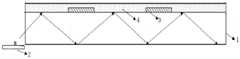
图1示出一种液晶显示器的结构示意图。FIG. 1 shows a schematic structural diagram of a liquid crystal display.
图2示出如图1所示的液晶显示器中不同位置的光栅衍射效率示意图。FIG. 2 shows a schematic diagram of the diffraction efficiency of the grating at different positions in the liquid crystal display shown in FIG. 1 .
图3示出根据本公开示例实施方式的一背光模组的结构示意图。FIG. 3 is a schematic structural diagram of a backlight module according to an exemplary embodiment of the present disclosure.
图4示出根据本公开示例实施方式的一背光模组中的取光光栅排布的概略示意图。FIG. 4 is a schematic diagram illustrating the arrangement of light extraction gratings in a backlight module according to an exemplary embodiment of the present disclosure.
图5示出根据本公开示例实施方式的一背光模组中的取光光栅的结构示意图。FIG. 5 is a schematic structural diagram of a light extraction grating in a backlight module according to an exemplary embodiment of the present disclosure.
图6示出根据本公开示例实施方式的一背光模组中分区设置的几何关系示意图。FIG. 6 is a schematic diagram showing the geometric relationship of partition arrangement in a backlight module according to an exemplary embodiment of the present disclosure.
图7示出根据本公开示例实施方式的一背光模组中的取光光栅排布的详细示意图。FIG. 7 is a detailed schematic diagram illustrating the arrangement of light extraction gratings in a backlight module according to an exemplary embodiment of the present disclosure.
图8示出一个周期内取光光栅分区排布结构示意图。FIG. 8 shows a schematic diagram of the arrangement structure of light-taking grating divisions in one period.
图9示出根据本公开示例实施方式的另一背光模组中的取光光栅排布的示意图。FIG. 9 is a schematic diagram illustrating the arrangement of light extraction gratings in another backlight module according to an example embodiment of the present disclosure.
图10示出根据本公开示例实施方式的一液晶显示器的结构示意图。FIG. 10 shows a schematic structural diagram of a liquid crystal display according to an example embodiment of the present disclosure.
具体实施方式Detailed ways
现在将参考附图更全面地描述示例实施方式。然而,示例实施方式能够以多种形式实施,且不应被理解为限于在此阐述的范例;所描述的特征、结构或特性可以以任何合适的方式结合在一个或更多实施方式中。在下面的描述中,提供许多具体细节从而给出对本公开的实施方式的充分理解。然而,本领域技术人员将意识到,可以实践本公开的技术方案而省略所述特定细节中的一个或更多,或者可以采用其它的方法、组元、装置、步骤等。Example embodiments will now be described more fully with reference to the accompanying drawings. Example embodiments can, however, be embodied in various forms and should not be construed as limited to the examples set forth herein; the described features, structures or characteristics may be combined in any suitable manner in one or more embodiments. In the following description, numerous specific details are provided in order to give a thorough understanding of the embodiments of the present disclosure. However, those skilled in the art will appreciate that the technical solutions of the present disclosure may be practiced without one or more of the specific details, or other methods, components, devices, steps, etc. may be employed.
需要指出的是,在附图中,为了图示的清晰可能会夸大层和区域的尺寸。而且可以理解,当元件或层被称为在另一元件或层“上”时,它可以直接在其他元件上,或者可以存在中间的层。另外,可以理解,当元件或层被称为在另一元件或层“下”时,它可以直接在其他元件下,或者可以存在一个以上的中间的层或元件。另外,还可以理解,当层或元件被称为在两层或两个元件“之间”时,它可以为两层或两个元件之间唯一的层,或还可以存在一个以上的中间层或元件。通篇相似的参考标记指示相似的元件。It should be noted that, in the drawings, the sizes of layers and regions may be exaggerated for clarity of illustration. It will also be understood that when an element or layer is referred to as being "on" another element or layer, it can be directly on the other element or intervening layers may be present. In addition, it will be understood that when an element or layer is referred to as being "under" another element or layer, it can be directly under the other element, or more than one intervening layer or element may be present. In addition, it will also be understood that when a layer or element is referred to as being 'between' two layers or elements, it can be the only layer between the two layers or elements, or more than one intervening layer may also be present or element. Like reference numerals indicate like elements throughout.
本公开的目的在于提供一种背光模组及使用其的液晶显示器。背光模组包括;导光板;设置于所述导光板一端的光源;设置在所述导光板的出光面上的呈阵列排布的多个取光光栅;以及覆盖在所述多个取光光栅上的平坦层;所述矩形阵列沿从所述导光板的近光端到远光端的方向分为等间距排列的多个区域,相邻两个区域的相邻列之间的间距为a+b,其中,a为同一区域内相邻列之间的间距,b为单个取光光栅的宽度。通过改变导光板上取光口(即取光光栅)的排布方式,将相临光束直径孔径内的取光口的相对位置位移一个取光口的距离,使取光口合理的分布到导光板上面,达到大大增加整体出光强度的技术效果;同时根据显示区的像素设计,定义一个合理分布的区域为一个周期,每个周期内取光口的光栅参数(/衍射效率)相同,设计不同周期内的光栅衍射效率,达到了均匀出光的技术效果;此外,根据本公开的一些示例性实施方式的液晶显示器,通过提出取光口借用的设计,在进一步增加出光强度的同时,可以增加液晶显示器的分辨率。The purpose of the present disclosure is to provide a backlight module and a liquid crystal display using the same. The backlight module includes: a light guide plate; a light source arranged at one end of the light guide plate; a plurality of light-taking gratings arranged in an array on the light-emitting surface of the light-guiding plate; and covering the plurality of light-taking gratings The rectangular array is divided into a plurality of regions arranged at equal intervals along the direction from the near light end to the far light end of the light guide plate, and the spacing between adjacent columns of two adjacent regions is a+ b, where a is the spacing between adjacent columns in the same area, and b is the width of a single light-taking grating. By changing the arrangement of the light-taking ports (ie light-taking gratings) on the light guide plate, the relative positions of the light-taking ports in the adjacent beam diameter apertures are shifted by a distance of the light-taking port, so that the light-taking ports are reasonably distributed to the guide. On the light plate, the technical effect of greatly increasing the overall light intensity is achieved; at the same time, according to the pixel design of the display area, a reasonably distributed area is defined as a period, and the grating parameters (/diffraction efficiency) of the light extraction port in each period are the same, but the design is different. The diffraction efficiency of the grating within the period achieves the technical effect of uniform light output; in addition, according to the liquid crystal display of some exemplary embodiments of the present disclosure, by proposing the design of borrowing the light extraction port, while further increasing the light output intensity, it is possible to increase the liquid crystal display The resolution of the display.
在对本公开的背光模组及使用其的液晶显示器进行详细说明之前,先介绍一种如图1所示的液晶显示器,如图1所示,在该液晶显示器中,调光光栅将led光源的朗伯体光线聚集到大角度耦合入导光板中,在导光板的上面或下面设置取出光栅,取出光栅的作用是将在导光板中全反射传播的大角度光线以准直角度取出,实现了高透过率的准直光源(背景光大部分可通过);然后通过结构设计在取光光栅上方设置遮光层阵列,出射准直光被遮光层吸收实现暗态,在显示的亮态时,给液晶层一组电压信号,液晶形成液晶光栅,经液晶光栅的衍射后出射,给液晶加不同的电压信号,可实现液晶光栅对入射光的不同衍射效率,实现多灰阶显示。Before describing the backlight module of the present disclosure and the liquid crystal display using the same, a liquid crystal display as shown in FIG. 1 is introduced. As shown in FIG. 1 , in the liquid crystal display, the dimming grating adjusts the LED light source The Lambertian light is collected at a large angle and coupled into the light guide plate, and a grating is set on the top or bottom of the light guide plate. A collimated light source with high transmittance (most of the background light can pass through); then a light-shielding layer array is set above the light-taking grating through structural design, and the outgoing collimated light is absorbed by the light-shielding layer to achieve a dark state. A set of voltage signals in the liquid crystal layer, the liquid crystal forms a liquid crystal grating, which is diffracted by the liquid crystal grating and then exits. Adding different voltage signals to the liquid crystal can realize different diffraction efficiencies of the liquid crystal grating to the incident light and realize multi-gray scale display.
在背光源设计中,取光光栅与显示的子像素一一对应,考虑到取光口和像素的匹配,在之前的设计中整面的取光口(即取光光栅)是以一定周期成阵列排布,这样的话,由于取光光栅并不是整面的,需要考虑开口率的影响,会造成整体的出光亮度很低。In the backlight design, the light-taking grating corresponds to the displayed sub-pixels one-to-one. Considering the matching of the light-taking port and the pixel, in the previous design, the entire light-taking port (ie the light-taking grating) was formed in a certain period of time. Array arrangement, in this case, since the light-taking grating is not the whole surface, the influence of the aperture ratio needs to be considered, which will cause the overall light-emitting brightness to be very low.
同时考虑出光的均匀性,每个出光口的出光效率不同,以50个出光口为例,为了达到出光的均匀性,整体的出光效率小于5%(如图2所示),同时目前的光栅制备工艺并不支持同时实现多个衍射效率的光栅结构制备。At the same time, considering the uniformity of light output, the light output efficiency of each light output port is different. Taking 50 light output ports as an example, in order to achieve the uniformity of light output, the overall light output efficiency is less than 5% (as shown in Figure 2). At the same time, the current grating The fabrication process does not support the fabrication of grating structures that simultaneously achieve multiple diffraction efficiencies.
而根据本公开提出的方案,可以解决以上问题,达到增加出光效率的技术效果。According to the solution proposed in the present disclosure, the above problems can be solved, and the technical effect of increasing the light extraction efficiency can be achieved.
下面结合图3-10分别对本公开的背光模组及使用其的液晶显示器进行详细说明,其中,图3示出根据本公开示例实施方式的一背光模组的结构示意图;图4示出根据本公开示例实施方式的一背光模组中的取光光栅排布的概略示意图;图5示出根据本公开示例实施方式的一背光模组中的取光光栅的结构示意图;图6示出根据本公开示例实施方式的一背光模组中分区设置的几何关系示意图;图7示出根据本公开示例实施方式的一背光模组中的取光光栅排布的详细示意图;图8示出一个周期内取光光栅分区排布结构示意图;图9示出根据本公开示例实施方式的另一背光模组中的取光光栅排布的示意图;图10示出根据本公开示例实施方式的一液晶显示器的结构示意图。The backlight module of the present disclosure and the liquid crystal display using the same will be described in detail below with reference to FIGS. 3-10, wherein FIG. 3 shows a schematic structural diagram of a backlight module according to an exemplary embodiment of the present disclosure; A schematic diagram of the arrangement of light-taking gratings in a backlight module according to an example embodiment of the disclosure is disclosed; FIG. 5 shows a schematic structural diagram of a light-taking grating in a backlight module according to an example embodiment of the present disclosure; A schematic diagram of the geometric relationship of the partition setting in a backlight module according to an example embodiment of the disclosure; FIG. 7 shows a detailed schematic diagram of the arrangement of light extraction gratings in a backlight module according to an example embodiment of the present disclosure; FIG. 8 shows a cycle Figure 9 shows a schematic diagram of the arrangement of light extraction gratings in another backlight module according to an example embodiment of the present disclosure; Figure 10 shows a liquid crystal display according to an example embodiment of the present disclosure. Schematic.
首先结合图3-9对本公开一示例实施方式的背光模组进行详细说明,其中,图3示出根据本公开示例实施方式的一背光模组的结构示意图;图4示出根据本公开示例实施方式的一背光模组中的取光光栅排布的概略示意图;图5示出根据本公开示例实施方式的一背光模组中的取光光栅的结构示意图;图6示出根据本公开示例实施方式的一背光模组中分区设置的几何关系示意图;图7示出根据本公开示例实施方式的一背光模组中的取光光栅排布的详细示意图;图8示出一个周期内取光光栅分区排布结构示意图;图9示出根据本公开示例实施方式的另一背光模组中的取光光栅排布的示意图。First, a backlight module according to an example embodiment of the present disclosure will be described in detail with reference to FIGS. 3-9 , wherein FIG. 3 shows a schematic structural diagram of a backlight module according to an example embodiment of the present disclosure; FIG. 4 shows an example implementation according to the present disclosure. Figure 5 shows a schematic view of the structure of the light extraction grating in a backlight module according to an example embodiment of the present disclosure; Figure 6 shows an example implementation according to the present disclosure. Figure 7 shows a detailed schematic diagram of the arrangement of light extraction gratings in a backlight module according to an exemplary embodiment of the present disclosure; Figure 8 shows a light extraction grating in one cycle A schematic diagram of a partition arrangement structure; FIG. 9 shows a schematic diagram of an arrangement of light extraction gratings in another backlight module according to an exemplary embodiment of the present disclosure.
图3示出根据本公开示例实施方式的一背光模组的结构示意图,图4示出根据本公开示例实施方式的一背光模组中的取光光栅排布的概略示意图,图7示出根据本公开示例实施方式的一背光模组中的取光光栅排布的详细示意图,结合图3、4和7,本公开提供一种背光模组,包括;导光板1;设置于所述导光板一端的光源2;设置在所述导光板的出光面上的呈阵列排布的多个取光光栅3;以及覆盖在所述多个取光光栅3上的平坦层4;所述矩形阵列沿从所述导光板的近光端到远光端的方向分为等间距排列的多个区域,相邻两个区域的相邻列之间的间距为a+b,其中,a为同一区域内相邻列之间的间距,b为单个取光光栅的宽度。FIG. 3 shows a schematic structural diagram of a backlight module according to an exemplary embodiment of the present disclosure, FIG. 4 shows a schematic schematic diagram of the arrangement of light extraction gratings in a backlight module according to an exemplary embodiment of the present disclosure, and FIG. A detailed schematic diagram of the arrangement of light-taking gratings in a backlight module according to an exemplary embodiment of the present disclosure. With reference to FIGS. 3 , 4 and 7 , the present disclosure provides a backlight module, comprising: a light guide plate 1 ; A
其中,导光板1用于接收由光源发出的光线,然后使这部分光线在导光板中全反射传播,当然本公开并不限于此,也可以是接收由光源发出的然后经自由曲面反射镜或其他类型反射镜反射和调光光栅调制后的光线。Wherein, the light guide plate 1 is used to receive the light emitted by the light source, and then make this part of the light propagate in the light guide plate through total reflection. Of course, the present disclosure is not limited to this. Other types of mirrors reflect and dimming the light modulated by the grating.
光源2较佳的为单色光源,可以为led即发光二极管,micro led即微发光二极管,OLED即有机发光二极管等。The
取光光栅3用于将在导光板中全反射传播的光线以准直的角度耦合出射,达到准直出光的技术效果。取光光栅3的具体结构如图5所示,一个取光光栅中可包含多个周期的光栅结构,其中p为光栅周期,d为两条相邻的光栅狭缝之间的间隔。光栅结构可以为如图5所示的简单光栅,也可以为阶梯光栅结构,本公开不以此为限。The light-taking
平坦层4用于将光栅层平坦化,所述平坦层的折射率低于所述导光板的折射率,要求使用低折射率(如1.25或更低)材料以使在所述导光板中传播的光线在投射到所述平坦层时发生全反射而不会由平坦层射出取光光栅层2,同时要求厚度≥1um以保证导光板内的全反射角较大。The
在本公开的一种示例性实施方式中,多个区域沿从所述导光板的近光端到远光端的方向分为多个周期;同一周期内的取光光栅的衍射效率相同。In an exemplary embodiment of the present disclosure, the multiple regions are divided into multiple periods along the direction from the near optical end to the far optical end of the light guide plate; the diffraction efficiencies of the light extraction gratings in the same period are the same.
在本公开的一种示例性实施方式中,不同周期内的取光光栅的衍射效率不同。In an exemplary embodiment of the present disclosure, the diffraction efficiencies of the light extraction gratings in different periods are different.
在本公开的一种示例性实施方式中,区域的宽度等于入射光线的光束直径e,任一周期内区域的数量n为a/b,其中a与b的取值为使得n为大于1的整数。In an exemplary embodiment of the present disclosure, the width of the region is equal to the beam diameter e of the incident light, and the number n of the regions in any period is a/b, where a and b are set such that n is greater than 1 Integer.
通过改变导光板上取光口(即取光光栅)的排布方式,将相临光束直径孔径内的取光口的相对位置位移一个取光口的距离,使取光口合理的分布到导光板上面,达到大大增加整体出光强度的技术效果。By changing the arrangement of the light-taking ports (ie light-taking gratings) on the light guide plate, the relative positions of the light-taking ports in the adjacent beam diameter apertures are shifted by a distance of the light-taking port, so that the light-taking ports are reasonably distributed to the guide. On the top of the light plate, the technical effect of greatly increasing the overall light intensity is achieved.
下面就如何选择光栅参数(光栅参数决定了光栅的衍射效率)进行具体说明:The following describes how to select the grating parameters (the grating parameters determine the diffraction efficiency of the grating):
理论上光栅的m级衍射波的衍射角θ仅由光栅周期P、入射波的波长λ以及入射角θ0决定,Theoretically, the diffraction angle θ of the m-order diffracted wave of the grating is only determined by the grating period P, the wavelength λ of the incident wave and the incident angle θ0,
sinθ-sinθ0=mλ/P(m=0,±1,±2,…) 公式1sinθ-sinθ0=mλ/P(m=0,±1,±2,…) Formula 1
一般情况下透射光栅的0级和一级衍射的衍射强度比较大,高阶的衍射级次相比前两者要小得多;0级衍射波是沿入射光方向的,一级衍射波的衍射方向可以由光栅的周期进行调控,所以此处对光线角度的调节一般使用的是一级衍射波(当出光方向等于或很接近入射波时,也可以使用零级衍射波)。当出光方向给定后,不同色光对应的光栅周期则由公式1决定。占空比一般为0.5,但在实际产品设计中可以偏离此值(比如出于调节出光的强度,平衡显示面板不同位置亮度的差异、工艺条件等原因)。光栅的高度,一般为300nm左右,可以稍微大一些如1um,也可以稍微小一些如200nm。出于消除、减弱或增强某种色光零级衍射波的目的,光栅的高度可以针对该波长进行设计,由于入射角是固定的,当该色波在光栅的栅条和空隙上的位相差为半波长奇数倍时,零级衍射波出现相干相消,零级波相干减弱,一级波增强;当位相差为波长整数倍时,零级波相干增强,一级波减弱。不同的色光可以选择不同的光栅高度,也可以选择相同的。简单来说,光栅周期决定出光角度,占空比和光栅高度主要影响出光角度的衍射效率。In general, the diffraction intensities of the 0th and first-order diffractions of the transmission grating are relatively large, and the higher-order diffraction orders are much smaller than the former two; the 0th-order diffraction wave is along the direction of the incident light, and the first-order diffraction wave The diffraction direction can be adjusted by the period of the grating, so the first-order diffracted wave is generally used to adjust the light angle here (when the light exit direction is equal to or very close to the incident wave, the zero-order diffracted wave can also be used). When the light exit direction is given, the grating period corresponding to different color light is determined by formula 1. The duty cycle is generally 0.5, but it can deviate from this value in actual product design (for example, to adjust the intensity of the light, balance the difference in brightness at different positions of the display panel, process conditions, etc.). The height of the grating is generally about 300nm, which can be slightly larger, such as 1um, or slightly smaller, such as 200nm. For the purpose of eliminating, weakening or enhancing the zeroth-order diffracted wave of a certain color light, the height of the grating can be designed for this wavelength. Since the incident angle is fixed, when the color wave has a phase difference between the grating and the gap of the grating, the phase difference is When the half wavelength is an odd multiple, the zero-order diffracted wave appears coherent cancellation, the zero-order wave coherence is weakened, and the first-order wave is enhanced; when the phase difference is an integer multiple of the wavelength, the zero-order wave coherence is enhanced, and the first-order wave is weakened. Different color lights can choose different grating heights or the same. In simple terms, the grating period determines the light exit angle, and the duty cycle and grating height mainly affect the diffraction efficiency of the light exit angle.
如图6所示,b为一个取光口(即取光光栅)的宽度,a为相邻取光口(即取光光栅)的间距(即前述的阵列的列间距a),c为液晶显示面板一个子像素大小,D为显示区的宽度,e为入射光线的光束直径,f为一个光束直径内取光口的个数,h为导光板的厚度。As shown in Figure 6, b is the width of one light-taking port (ie, light-taking grating), a is the spacing between adjacent light-taking ports (ie, light-taking grating) (ie, the column spacing a of the aforementioned array), and c is the liquid crystal The size of a sub-pixel of the display panel, D is the width of the display area, e is the beam diameter of the incident light, f is the number of light-taking ports in a beam diameter, and h is the thickness of the light guide plate.
根据几何关系有:According to the geometric relationship there are:
e=h*tanθ 公式2e=h*
f=e/c 公式3f=e/
c=a+b 公式4c=a+
根据公式2-4的几何关系,即可选择合适的e,f值。According to the geometric relationship of formula 2-4, the appropriate e and f values can be selected.
图8示出一个周期(如周期1)内取光光栅分区排布结构示意图,如图8所示,区域1-区域n的宽度为e,每个区域内具有的取光口(即取光光栅)数为f,每个区域内取光口(即取光光栅)的宽度和间距不变,区域之间的距离为b,即每个区域之间的距离相差一个取光口(即取光光栅)的大小,n=a/b。n个区域组成一个大的光栅阵列周期1,这个周期1的宽度为n(e+b),周期1内光栅的参数相同,即光栅对相同角度和波长的入射光的衍射效率相同,为η1。需要说明的是,液晶显示面板的设计也要随之改变。Fig. 8 shows a schematic diagram of the arrangement of the light-taking grating partitions in one period (such as period 1). As shown in Fig. 8, the width of the region 1-region n is e, and the light-taking port (that is, the light-taking port) in each region The number of gratings) is f, the width and spacing of the light-taking ports (that is, the light-taking gratings) in each area are unchanged, and the distance between the regions is b, that is, the distance between each area is different by one light-taking port (that is, taking the light grating). grating), n=a/b. The n regions form a large grating array period 1, the width of this period 1 is n(e+b), and the parameters of the grating in period 1 are the same, that is, the diffraction efficiency of the grating to the incident light of the same angle and wavelength is the same, which is η1 . It should be noted that the design of the liquid crystal display panel should also be changed accordingly.
在本公开的一种示例性实施方式中,通过调整不同周期内的取光光栅的衍射效率使得所述取光光栅层中所有取光光栅出射的光通量相同。也就是说根据液晶显示面板显示区的像素设计,定义一个合理分布的区域为一个周期,每个周期内取光口的光栅参数(/衍射效率)相同,设计不同周期内的光栅衍射效率,使得所述取光光栅层中所有取光光栅出射的光通量相同从而达到均匀出光的技术效果。In an exemplary embodiment of the present disclosure, the light fluxes emitted by all the light extraction gratings in the light extraction grating layer are the same by adjusting the diffraction efficiencies of the light extraction gratings in different periods. That is to say, according to the pixel design of the display area of the liquid crystal display panel, a reasonably distributed area is defined as a period, and the grating parameters (/diffraction efficiency) of the light extraction port in each period are the same, and the diffraction efficiency of the grating in different periods is designed so that The light fluxes emitted by all the light extraction gratings in the light extraction grating layer are the same, so as to achieve the technical effect of uniform light extraction.
下面介绍具体如何计算不同周期内的光栅衍射效率。为了实现所有取光光栅出射的光通量相同的目的,可通过以下公式计算任一周期内的取光光栅所需要的衍射效率:The following describes how to calculate the diffraction efficiency of the grating in different periods. In order to achieve the same purpose of the light flux emitted by all the light-taking gratings, the diffraction efficiency required by the light-taking gratings in any period can be calculated by the following formula:
1*η1=α1*η1=α
(1-α)*η2=α(1-α)*η2=α
……
(1-(m-1)α)*ηm=α(1-(m-1)α)*ηm=α
其中,α为任一取光光栅出射的光通量,m为所述多个周期的数量,ηm为第m个周期内的取光光栅所需要的衍射效率。Wherein, α is the light flux emitted by any light extraction grating, m is the number of the plurality of periods, and ηm is the diffraction efficiency required by the light extraction grating in the mth period.
在本公开的一种示例性实施方式中,区域中任一以相邻四个取光光栅的中心点作为顶点的矩形的中心点上均还设置有取光光栅。如图9所示,为了增加整体的出光强度,在另一维度也增加了取光光栅的排布,这样的排布方式适用于像素借用的液晶显示面板设计方式,即中间的取光口(即取光光栅)为周围4个取光口(即取光光栅)的共用,这样做在达到更高出光效率的同时,还增加了显示的分辨率密度。In an exemplary embodiment of the present disclosure, a light extraction grating is further provided on the center point of any rectangle whose vertexes are the center points of the four adjacent light extraction gratings in the region. As shown in Figure 9, in order to increase the overall light output intensity, the arrangement of the light extraction grating is also added in another dimension. This arrangement is suitable for the liquid crystal display panel design method borrowed by the pixels, that is, the middle light extraction port ( That is, the light taking grating) is shared by the four surrounding light taking ports (that is, the light taking grating), which not only achieves higher light extraction efficiency, but also increases the resolution density of the display.
下面结合图10对使用本公开前述的背光模组的液晶显示器进行详细说明。如图10所示,本公开的液晶显示器包括:任一前述的背光模组;设置在所述背光模组上的液晶显示面板5,其中所述液晶显示面板包括:设置在所述背光模组上的像素层51,其中所述像素层中的各像素与所述背光模组中的各取光光栅一一对应;以及设置在所述像素层上的彩膜基板52。The liquid crystal display using the aforementioned backlight module of the present disclosure will be described in detail below with reference to FIG. 10 . As shown in FIG. 10 , the liquid crystal display of the present disclosure includes: any one of the aforementioned backlight modules; a liquid
其中像素层51可包括共用电极及正电极层511、液晶层512和取向层513等,液晶层512选用向列相液晶即可,其他液晶也可以,液晶层512厚度在0.1-10um,用于形成液晶光栅。The pixel layer 51 can include a common electrode and a positive electrode layer 511, a
彩膜基板52包括彩膜521和上盖板522。The
本公开的一种示例性实施方式中,所述彩膜基板52中的彩膜521为量子点彩膜。采用量子点彩膜的作用有两个,一是用于实现彩色化,背光选用单色短波长光源,激发RGB(红绿蓝)三色量子点实现彩色显示;二是把出射光线进行散射处理,本公开出射的光线有一定指向性,需要散射化处理,而量子点彩膜正好有很好的散射特性,所以B量子点也需要做在彩膜上,增加视角。In an exemplary embodiment of the present disclosure, the
此外,本公开优选驱动电极及TFT即薄膜晶体管做在彩膜上,是因为现有的纳米压印工艺只能实现8寸以下样品制作,完成纳米压印工艺后就不能进行Array(阵列)工艺。所以优选AOC结构,不排除以后纳米压印可以在大基板上进行的可能。In addition, the present disclosure prefers that the driving electrodes and TFTs, that is, thin film transistors, are formed on the color filter, because the existing nanoimprinting process can only realize the production of samples below 8 inches, and the Array process cannot be performed after the nanoimprinting process is completed. . Therefore, the AOC structure is preferred, and the possibility that nanoimprinting can be performed on a large substrate in the future is not ruled out.
在本公开的一种示例性实施方式中,所述液晶显示器还包括设置在同时邻近于所述光源和所述导光板的近光端的位置的反射镜6,用于将所述光源发射的光线以一预定角度反射进入所述导光板。反射镜6可为自由曲面反射镜,自由曲面可以选择抛物面或球面,但是曲面的横向轴线与水平方向成一定夹角θ,θ小于等于50°,作用是将光源入射后的光线反射成一定角度出射,要求的较佳出射角范围为小于20°,但本公开不以此为限,也可以大于20°。In an exemplary embodiment of the present disclosure, the liquid crystal display further includes a reflector 6 disposed adjacent to both the light source and the near-light end of the light guide plate, for reflecting the light emitted by the light source reflected into the light guide plate at a predetermined angle. The reflector 6 can be a free-form reflector, and the free-form surface can be a paraboloid or a spherical surface, but the lateral axis of the curved surface forms a certain angle θ with the horizontal direction, and θ is less than or equal to 50°, and the function is to reflect the incident light of the light source into a certain angle. For outgoing, the preferred range of outgoing angle required is less than 20°, but the present disclosure is not limited to this, and may also be greater than 20°.
通过以上的详细描述,本领域的技术人员易于理解,根据本公开实示例性实施方式的背光模组及使用其的液晶显示器具有以下优点中的一个或几个。From the above detailed description, those skilled in the art can easily understand that the backlight module according to the exemplary embodiment of the present disclosure and the liquid crystal display using the same have one or more of the following advantages.
根据本公开的一些示例性实施方式的背光模组,通过改变导光板上取光口(即取光光栅)的排布方式,将相临光束直径孔径内的取光口的相对位置位移一个取光口的距离,使取光口合理的分布到导光板上面,达到大大增加整体出光强度的技术效果。According to the backlight modules of some exemplary embodiments of the present disclosure, by changing the arrangement of the light-taking ports (ie, light-taking gratings) on the light guide plate, the relative positions of the light-taking ports in the adjacent beam diameter apertures are shifted by one value. The distance of the light port makes the light port reasonably distributed on the light guide plate, and achieves the technical effect of greatly increasing the overall light intensity.
根据本公开的一些示例性实施方式的背光模组,同时根据显示区的像素设计,定义一个合理分布的区域为一个周期,每个周期内取光口的光栅参数(/衍射效率)相同,设计不同周期内的光栅衍射效率,达到了均匀出光的技术效果。According to the backlight module of some exemplary embodiments of the present disclosure, according to the pixel design of the display area, a reasonably distributed area is defined as a period, and the grating parameters (/diffraction efficiency) of the light extraction port in each period are the same. The diffraction efficiency of the grating in different periods achieves the technical effect of uniform light output.
根据本公开的一些示例性实施方式的液晶显示器,通过提出取光口借用的设计,在进一步增加出光强度的同时,可以增加液晶显示器的分辨率。According to the liquid crystal display of some exemplary embodiments of the present disclosure, the resolution of the liquid crystal display can be increased while further increasing the light output intensity by proposing a design borrowed from the light extraction port.
本领域技术人员在考虑说明书及实践这里公开的发明后,将容易想到本发明的其它实施方案。本申请旨在涵盖本发明的任何变型、用途或者适应性变化,这些变型、用途或者适应性变化遵循本发明的一般性原理并包括本发明未公开的本技术领域中的公知常识或惯用技术手段。说明书和实施例仅被视为示例性的,本发明的真正范围和精神由下面的权利要求指出。Other embodiments of the invention will readily occur to those skilled in the art upon consideration of the specification and practice of the invention disclosed herein. This application is intended to cover any variations, uses or adaptations of the invention which follow the general principles of the invention and which include common knowledge or conventional techniques in the art not disclosed by the invention . The specification and examples are to be regarded as exemplary only, with the true scope and spirit of the invention being indicated by the following claims.
应当理解的是,本发明并不局限于上面已经描述并在附图中示出的精确结构,并且可以在不脱离其范围进行各种修改和改变。本发明的范围仅由所附的权利要求来限制。It should be understood that the present invention is not limited to the precise structures described above and illustrated in the accompanying drawings, and that various modifications and changes may be made without departing from its scope. The scope of the present invention is limited only by the appended claims.
Claims (6)
Translated fromChinesePriority Applications (2)
| Application Number | Priority Date | Filing Date | Title |
|---|---|---|---|
| CN201710889702.3ACN107621729B (en) | 2017-09-27 | 2017-09-27 | Backlight module and liquid crystal display using same |
| US15/992,890US10705282B2 (en) | 2017-09-27 | 2018-05-30 | Backlight module comprising a plurality of light extraction gratings arranged in an array on a light emission surface of a light guide plate and liquid crystal display using the same |
Applications Claiming Priority (1)
| Application Number | Priority Date | Filing Date | Title |
|---|---|---|---|
| CN201710889702.3ACN107621729B (en) | 2017-09-27 | 2017-09-27 | Backlight module and liquid crystal display using same |
Publications (2)
| Publication Number | Publication Date |
|---|---|
| CN107621729A CN107621729A (en) | 2018-01-23 |
| CN107621729Btrue CN107621729B (en) | 2020-07-10 |
Family
ID=61091138
Family Applications (1)
| Application Number | Title | Priority Date | Filing Date |
|---|---|---|---|
| CN201710889702.3AExpired - Fee RelatedCN107621729B (en) | 2017-09-27 | 2017-09-27 | Backlight module and liquid crystal display using same |
Country Status (2)
| Country | Link |
|---|---|
| US (1) | US10705282B2 (en) |
| CN (1) | CN107621729B (en) |
Families Citing this family (12)
| Publication number | Priority date | Publication date | Assignee | Title |
|---|---|---|---|---|
| CN107238974B (en) | 2017-07-24 | 2021-03-02 | 京东方科技集团股份有限公司 | Backlight source and liquid crystal display module |
| CN108415191A (en)* | 2018-03-15 | 2018-08-17 | 京东方科技集团股份有限公司 | Display device, electronic equipment and display methods |
| CN110389469B (en)* | 2018-04-20 | 2021-03-30 | 京东方科技集团股份有限公司 | Display device and display method thereof |
| CN108646412B (en)* | 2018-05-10 | 2021-05-14 | 京东方科技集团股份有限公司 | Near-eye display device and near-eye display method |
| CN108710226B (en)* | 2018-05-24 | 2021-04-23 | 京东方科技集团股份有限公司 | A transparent display device and display method |
| CN108646338B (en) | 2018-07-02 | 2019-12-31 | 京东方科技集团股份有限公司 | A kind of backlight module and display device |
| CN109031789B (en)* | 2018-09-20 | 2021-02-09 | 京东方科技集团股份有限公司 | Display device |
| WO2020122119A1 (en)* | 2018-12-11 | 2020-06-18 | 富士フイルム株式会社 | Liquid crystal diffraction element and light guide element |
| CN109856861B (en)* | 2019-04-02 | 2021-04-16 | 京东方科技集团股份有限公司 | Display panel, display device and driving method of display panel |
| CN113703174B (en)* | 2020-05-22 | 2024-08-06 | 富泰华工业(深圳)有限公司 | Holographic display device |
| CN111708220A (en)* | 2020-06-23 | 2020-09-25 | 武汉华星光电技术有限公司 | Backlight source, display substrate and display device |
| CN116466514B (en)* | 2023-04-18 | 2024-07-16 | 业成光电(深圳)有限公司 | Light emitting layout structure of backlight module |
Citations (5)
| Publication number | Priority date | Publication date | Assignee | Title |
|---|---|---|---|---|
| CN102122013A (en)* | 2011-03-29 | 2011-07-13 | 湖北大学 | Optical waveguide type space array light separation output guide plate for panel LCD (Liquid Crystal Display) |
| CN105074322A (en)* | 2013-03-13 | 2015-11-18 | 惠普发展公司,有限责任合伙企业 | Backlight with collimating reflector |
| CA2990591A1 (en)* | 2015-03-30 | 2016-10-06 | Leia Inc. | 2d/3d mode-switchable electronic display with dual layer backlight |
| CN106597658A (en)* | 2017-03-09 | 2017-04-26 | 京东方科技集团股份有限公司 | Display panel and display apparatus |
| CN106662700A (en)* | 2014-07-30 | 2017-05-10 | 镭亚股份有限公司 | Multibeam diffraction grating-based color backlighting |
Family Cites Families (12)
| Publication number | Priority date | Publication date | Assignee | Title |
|---|---|---|---|---|
| JP3828402B2 (en)* | 2001-11-08 | 2006-10-04 | 株式会社日立製作所 | BACKLIGHTING DEVICE, LIQUID CRYSTAL DISPLAY DEVICE USING SAME, AND LIGHTING METHOD FOR LIQUID CRYSTAL DISPLAY DEVICE |
| CN1932602A (en)* | 2005-09-14 | 2007-03-21 | 鸿富锦精密工业(深圳)有限公司 | Light-conducting plate |
| KR100862667B1 (en)* | 2006-10-31 | 2008-10-10 | 삼성전자주식회사 | High power light guide plate, backlight unit and display using the same |
| KR101345383B1 (en)* | 2007-06-08 | 2013-12-24 | 삼성전자주식회사 | Method for manufacturing the all-in-one type light guide plate |
| JP2009123553A (en)* | 2007-11-15 | 2009-06-04 | Sumitomo Chemical Co Ltd | Light guide plate, surface light source device, and liquid crystal display device |
| WO2011004306A1 (en)* | 2009-07-10 | 2011-01-13 | Koninklijke Philips Electronics N.V. | Free form lighting module |
| KR101808185B1 (en)* | 2010-12-27 | 2018-01-19 | 삼성전자 주식회사 | Light guide plate, backlight unit and display apparatus including the same and manufacturing method thereof |
| JP5538571B2 (en)* | 2011-08-12 | 2014-07-02 | 株式会社フジクラ | Light emitting device |
| CN103454714B (en)* | 2012-05-28 | 2016-08-24 | 元太科技工业股份有限公司 | Light guide plate and electrophoretic display device capable of switching between color mode and black-and-white mode |
| PT3248058T (en)* | 2015-01-19 | 2020-07-28 | Leia Inc | Unidirectional grating-based backlighting employing a reflective island |
| KR102390375B1 (en)* | 2015-08-26 | 2022-04-25 | 삼성전자주식회사 | Backlight unit and 3D image display apparatus |
| KR102330204B1 (en)* | 2016-01-07 | 2021-11-23 | 삼성전자주식회사 | Method of generating directional rays and apparatuses performing the same |
- 2017
- 2017-09-27CNCN201710889702.3Apatent/CN107621729B/ennot_activeExpired - Fee Related
- 2018
- 2018-05-30USUS15/992,890patent/US10705282B2/ennot_activeExpired - Fee Related
Patent Citations (5)
| Publication number | Priority date | Publication date | Assignee | Title |
|---|---|---|---|---|
| CN102122013A (en)* | 2011-03-29 | 2011-07-13 | 湖北大学 | Optical waveguide type space array light separation output guide plate for panel LCD (Liquid Crystal Display) |
| CN105074322A (en)* | 2013-03-13 | 2015-11-18 | 惠普发展公司,有限责任合伙企业 | Backlight with collimating reflector |
| CN106662700A (en)* | 2014-07-30 | 2017-05-10 | 镭亚股份有限公司 | Multibeam diffraction grating-based color backlighting |
| CA2990591A1 (en)* | 2015-03-30 | 2016-10-06 | Leia Inc. | 2d/3d mode-switchable electronic display with dual layer backlight |
| CN106597658A (en)* | 2017-03-09 | 2017-04-26 | 京东方科技集团股份有限公司 | Display panel and display apparatus |
Also Published As
| Publication number | Publication date |
|---|---|
| US20190094447A1 (en) | 2019-03-28 |
| US10705282B2 (en) | 2020-07-07 |
| CN107621729A (en) | 2018-01-23 |
Similar Documents
| Publication | Publication Date | Title |
|---|---|---|
| CN107621729B (en) | Backlight module and liquid crystal display using same | |
| US11187844B2 (en) | Display device and control method thereof | |
| CN106647093A (en) | Liquid crystal display panel, liquid crystal display and displaying method thereof | |
| JP6081073B2 (en) | Display device and liquid crystal display device | |
| US9201270B2 (en) | Directional backlight with a modulation layer | |
| CN108646338B (en) | A kind of backlight module and display device | |
| CN107490901B (en) | Dual-view display panel and display device | |
| JP7062366B2 (en) | Display device, display method and color separation element | |
| US11106074B2 (en) | Display panel and display device | |
| US9075255B2 (en) | Display device | |
| CN107918233B (en) | a display device | |
| TWI272428B (en) | Liquid-crystal display device and method of fabricating same | |
| JP5912768B2 (en) | Display device | |
| CN107219685A (en) | The display methods of display device and display device | |
| CN106291943A (en) | A kind of display floater and display device | |
| US11327360B2 (en) | Display panel, display apparatus, driving method of the display panel, and storage medium | |
| CN109709720B (en) | Backlight Modules and Display Devices | |
| CN108333835A (en) | Side entrance back module, display device | |
| WO2020007281A1 (en) | Display apparatus and control method for display apparatus, and display device | |
| CN107357075A (en) | Display panel and display device | |
| CN110646989B (en) | Display panel, display device and control method thereof | |
| CN103969719A (en) | Triangular prism plate and display device | |
| US10613372B2 (en) | Display device and display method | |
| CN206096710U (en) | Display device | |
| US9448434B2 (en) | Liquid crystal display panel and method for driving the same |
Legal Events
| Date | Code | Title | Description |
|---|---|---|---|
| PB01 | Publication | ||
| PB01 | Publication | ||
| SE01 | Entry into force of request for substantive examination | ||
| SE01 | Entry into force of request for substantive examination | ||
| GR01 | Patent grant | ||
| GR01 | Patent grant | ||
| CF01 | Termination of patent right due to non-payment of annual fee | Granted publication date:20200710 | |
| CF01 | Termination of patent right due to non-payment of annual fee |