CN107608559B - Force sensing unit, preparation method thereof, touch panel and touch display panel - Google Patents
Force sensing unit, preparation method thereof, touch panel and touch display panelDownload PDFInfo
- Publication number
- CN107608559B CN107608559BCN201710959004.6ACN201710959004ACN107608559BCN 107608559 BCN107608559 BCN 107608559BCN 201710959004 ACN201710959004 ACN 201710959004ACN 107608559 BCN107608559 BCN 107608559B
- Authority
- CN
- China
- Prior art keywords
- substrate
- sensing
- electrode
- electrodes
- force
- Prior art date
- Legal status (The legal status is an assumption and is not a legal conclusion. Google has not performed a legal analysis and makes no representation as to the accuracy of the status listed.)
- Expired - Fee Related
Links
Images


Classifications
- G—PHYSICS
- G06—COMPUTING OR CALCULATING; COUNTING
- G06F—ELECTRIC DIGITAL DATA PROCESSING
- G06F3/00—Input arrangements for transferring data to be processed into a form capable of being handled by the computer; Output arrangements for transferring data from processing unit to output unit, e.g. interface arrangements
- G06F3/01—Input arrangements or combined input and output arrangements for interaction between user and computer
- G06F3/03—Arrangements for converting the position or the displacement of a member into a coded form
- G06F3/041—Digitisers, e.g. for touch screens or touch pads, characterised by the transducing means
- G06F3/0414—Digitisers, e.g. for touch screens or touch pads, characterised by the transducing means using force sensing means to determine a position
- G—PHYSICS
- G06—COMPUTING OR CALCULATING; COUNTING
- G06F—ELECTRIC DIGITAL DATA PROCESSING
- G06F3/00—Input arrangements for transferring data to be processed into a form capable of being handled by the computer; Output arrangements for transferring data from processing unit to output unit, e.g. interface arrangements
- G06F3/01—Input arrangements or combined input and output arrangements for interaction between user and computer
- G06F3/03—Arrangements for converting the position or the displacement of a member into a coded form
- G06F3/041—Digitisers, e.g. for touch screens or touch pads, characterised by the transducing means
- G06F3/0412—Digitisers structurally integrated in a display
- G—PHYSICS
- G06—COMPUTING OR CALCULATING; COUNTING
- G06F—ELECTRIC DIGITAL DATA PROCESSING
- G06F3/00—Input arrangements for transferring data to be processed into a form capable of being handled by the computer; Output arrangements for transferring data from processing unit to output unit, e.g. interface arrangements
- G06F3/01—Input arrangements or combined input and output arrangements for interaction between user and computer
- G06F3/03—Arrangements for converting the position or the displacement of a member into a coded form
- G06F3/041—Digitisers, e.g. for touch screens or touch pads, characterised by the transducing means
- G06F3/0414—Digitisers, e.g. for touch screens or touch pads, characterised by the transducing means using force sensing means to determine a position
- G06F3/04144—Digitisers, e.g. for touch screens or touch pads, characterised by the transducing means using force sensing means to determine a position using an array of force sensing means
- G—PHYSICS
- G06—COMPUTING OR CALCULATING; COUNTING
- G06F—ELECTRIC DIGITAL DATA PROCESSING
- G06F3/00—Input arrangements for transferring data to be processed into a form capable of being handled by the computer; Output arrangements for transferring data from processing unit to output unit, e.g. interface arrangements
- G06F3/01—Input arrangements or combined input and output arrangements for interaction between user and computer
- G06F3/03—Arrangements for converting the position or the displacement of a member into a coded form
- G06F3/041—Digitisers, e.g. for touch screens or touch pads, characterised by the transducing means
- G06F3/0416—Control or interface arrangements specially adapted for digitisers
- G06F3/04164—Connections between sensors and controllers, e.g. routing lines between electrodes and connection pads
- G—PHYSICS
- G06—COMPUTING OR CALCULATING; COUNTING
- G06F—ELECTRIC DIGITAL DATA PROCESSING
- G06F2203/00—Indexing scheme relating to G06F3/00 - G06F3/048
- G06F2203/041—Indexing scheme relating to G06F3/041 - G06F3/045
- G06F2203/04103—Manufacturing, i.e. details related to manufacturing processes specially suited for touch sensitive devices
Landscapes
- Engineering & Computer Science (AREA)
- General Engineering & Computer Science (AREA)
- Theoretical Computer Science (AREA)
- Human Computer Interaction (AREA)
- Physics & Mathematics (AREA)
- General Physics & Mathematics (AREA)
- Computer Networks & Wireless Communication (AREA)
- Position Input By Displaying (AREA)
- Force Measurement Appropriate To Specific Purposes (AREA)
Abstract
Translated fromChinese
Description
Translated fromChinese技术领域technical field
本发明涉及显示技术领域,具体涉及一种力感单元及其制备方法、触控面板和触控显示面板。The present invention relates to the field of display technology, in particular to a force-sensing unit and a preparation method thereof, a touch panel and a touch display panel.
背景技术Background technique
触控显示面板(Touch Screen Panel)已成为当前最简便的人机交互的电子设备,其具有触控功能和显示功能的结合特性,可以广泛适用于目前随身携带的电子装置,如智能手机,平板电脑或笔记本电脑等。Touch Screen Panel has become the most convenient electronic device for human-computer interaction. It has the combination of touch function and display function, and can be widely used in electronic devices that are currently carried around, such as smart phones and tablets. computer or laptop etc.
对于触控面板,无论是电容屏还是电阻屏,均是用于确定触控点的二维位置。随着技术的飞速发展,为了进一步丰富人机交互的多样性,进一步提高人机交互的使用体验,目前已有部分触控面板具有压力感应功能。具有压力感应功能的触控也称压力感应触控或压力触控(Force Touch),触控面板在感知触摸位置的同时,还可以感知触摸的压力,从而根据触控点位置和压力来调用相应的功能或进行相应的显示,将触控技术扩展到三维(3-Dimension,3D)范畴。For a touch panel, whether it is a capacitive screen or a resistive screen, it is used to determine the two-dimensional position of the touch point. With the rapid development of technology, in order to further enrich the diversity of human-computer interaction and further improve the user experience of human-computer interaction, some touch panels currently have a pressure sensing function. The touch with pressure-sensing function is also called pressure-sensing touch or Force Touch. The touch panel can sense the pressure of the touch while sensing the touch position, so as to call the corresponding touch point according to the position and pressure of the touch point. function or display accordingly, extending the touch technology to the three-dimensional (3-Dimension, 3D) category.
目前,虽然现有技术提出了多种压力感应触控的方案,但所感应的力均是垂直于触控面板方向的压力,而无法感应平行于触控面板方向的水平力。At present, although the prior art proposes a variety of pressure-sensitive touch solutions, the sensed force is the pressure perpendicular to the direction of the touch panel, and cannot sense the horizontal force parallel to the direction of the touch panel.
发明内容SUMMARY OF THE INVENTION
本发明实施例所要解决的技术问题是,提供一种力感单元及其制备方法、触控面板和触控显示面板,以感知平行于触控面板方向的水平力。The technical problem to be solved by the embodiments of the present invention is to provide a force sensing unit and a manufacturing method thereof, a touch panel and a touch display panel to sense a horizontal force parallel to the direction of the touch panel.
为了解决上述技术问题,本发明实施例提供了一种力感单元,包括相对设置的第一基板和第二基板,所述第一基板被配置为在受到水平趋向力时相对所述第二基板移动,以确定触摸位置和施加在触摸位置的水平趋向力的方向和/或大小。In order to solve the above-mentioned technical problem, an embodiment of the present invention provides a force sensing unit, comprising a first substrate and a second substrate disposed opposite to each other, the first substrate is configured to be opposite to the second substrate when subjected to a horizontal force Movement to determine the touch location and the direction and/or magnitude of the horizontal tending force applied at the touch location.
可选地,所述第一基板朝向第二基板的表面上设置有一个柱状的感应电极,所述第二基板朝向第一基板的表面上设置有多个柱状的方向电极;或者,所述第一基板朝向第二基板的表面上设置有多个柱状的方向电极,所述第二基板朝向第一基板的表面上设置有一个柱状的感应电极;Optionally, a columnar sensing electrode is disposed on the surface of the first substrate facing the second substrate, and a plurality of columnar directional electrodes are disposed on the surface of the second substrate facing the first substrate; or, the first substrate A plurality of columnar directional electrodes are arranged on the surface of a substrate facing the second substrate, and a columnar sensing electrode is arranged on the surface of the second substrate facing the first substrate;
所述多个方向电极以所述感应电极为中心对称设置,所述感应电极被配置为在第一基板相对第二基板移动时,通过感知所述感应电极与方向电极之间的距离,确定触摸位置和施加在触摸位置的水平趋向力的方向和/或大小。The plurality of directional electrodes are symmetrically arranged around the sensing electrode, and the sensing electrodes are configured to determine the touch by sensing the distance between the sensing electrodes and the directional electrodes when the first substrate moves relative to the second substrate. The location and the direction and/or magnitude of the horizontal tending force applied at the touch location.
可选地,还包括用于分别向所述多个方向电极施加不同电压信号的多条扫描引出线,以及用于采集所述感应电极的感应电压的一条感应引出线,所述感应引出线连接所述感应电极,每条扫描引出线连接一个方向电极。Optionally, it also includes a plurality of scanning lead lines for applying different voltage signals to the plurality of directional electrodes respectively, and a sensing lead line for collecting the induced voltage of the sensing electrodes, and the sensing lead lines are connected For the sensing electrodes, each scanning lead line is connected to a direction electrode.
可选地,所述多个方向电极为2~8个方向电极。Optionally, the plurality of directional electrodes are 2-8 directional electrodes.
可选地,所述第一基板上设置有一个柱状的方向电极,所述第二基板上设置有多个柱状的感应电极;或者,所述第一基板上设置有多个柱状的感应电极,所述第二基板上设置有一个柱状的方向电极;Optionally, a columnar directional electrode is arranged on the first substrate, and a plurality of columnar sensing electrodes are arranged on the second substrate; or, a plurality of columnar induction electrodes are arranged on the first substrate, A columnar directional electrode is arranged on the second substrate;
所述多个感应电极以所述方向电极为中心对称设置,所述感应电极被配置为在第一基板相对第二基板移动时,通过感知所述感应电极与方向电极之间的距离,确定触摸位置和施加在触摸位置的水平趋向力的方向和/或大小。The plurality of sensing electrodes are symmetrically arranged around the directional electrode, and the sensing electrodes are configured to determine the touch by sensing the distance between the sensing electrodes and the directional electrodes when the first substrate moves relative to the second substrate. The location and the direction and/or magnitude of the horizontal tending force applied at the touch location.
可选地,还包括用于向所述方向电极施加电压信号的一条扫描引出线,以及用于分别采集所述多个感应电极的感应电压的多条感应引出线,每条感应引出线连接一个感应电极,所述扫描引出线连接所述方向电极。Optionally, it also includes a scanning lead line for applying a voltage signal to the directional electrodes, and a plurality of sensing lead lines for respectively collecting the induced voltages of the plurality of sensing electrodes, and each sensing lead line is connected to one Induction electrodes, and the scanning lead lines are connected to the direction electrodes.
可选地,所述多个感应电极为2~8个感应电极。Optionally, the plurality of sensing electrodes are 2-8 sensing electrodes.
可选地,所述扫描引出线和感应引出线设置在所述第一基板或第二基板上;所述感应引出线通过感应连接电极与所述感应电极连接,所述扫描引出线通过扫描连接电极与所述方向电极连接。Optionally, the scanning lead-out line and the sensing lead-out line are arranged on the first substrate or the second substrate; the sensing lead-out line is connected to the sensing electrode through an inductive connection electrode, and the scan lead-out line is connected through a scan connection An electrode is connected to the direction electrode.
可选地,所述第一基板或第二基板上还设置有用于减小第一基板与第二基板相对运动摩擦力的润滑层,所述润滑层与对向基板上设置的感应电极或方向电极接触。Optionally, the first substrate or the second substrate is further provided with a lubricating layer for reducing the frictional force of the relative motion between the first substrate and the second substrate, and the lubricating layer is connected to the sensing electrode or direction provided on the opposite substrate. electrode contact.
可选地,所述第一基板或第二基板上还设置有包括多个介质块的介质层,每个介质块设置在所述感应电极与方向电极之间。Optionally, a dielectric layer including a plurality of dielectric blocks is further disposed on the first substrate or the second substrate, and each dielectric block is disposed between the sensing electrode and the direction electrode.
可选地,所述第一基板或第二基板上还设置有绝缘层,所述绝缘层设置在所述感应电极或方向电极的外围。Optionally, an insulating layer is further disposed on the first substrate or the second substrate, and the insulating layer is disposed on the periphery of the sensing electrode or the direction electrode.
本发明实施例还提供了一种触控面板,包括矩阵排布的多个上述的力感单元,还包括扫描电路和感应电路,所述扫描电路用于以逐行扫描方式向一行中的每个力感单元输入电压信号,所述感应电路用于采集该行的每个力感单元的感应电压,并根据所述感应电压确定触摸位置和施加在触摸位置的水平趋向力的方向和/或大小。An embodiment of the present invention further provides a touch panel, which includes a plurality of the above-mentioned force-sensing units arranged in a matrix, and further includes a scanning circuit and a sensing circuit, where the scanning circuit is used to scan each row in a row by row by row. Each force-sensing unit inputs a voltage signal, and the sensing circuit is used to collect the induced voltage of each force-sensing unit in the row, and determine the touch position and the direction of the horizontal force applied at the touch position and/or according to the induced voltage size.
本发明实施例还提供了一种触控显示面板,包括显示面板和上述的触控面板。An embodiment of the present invention further provides a touch display panel, including a display panel and the above-mentioned touch panel.
为了解决上述技术问题,本发明实施例还提供了力感单元的制备方法,包括:In order to solve the above-mentioned technical problems, the embodiment of the present invention also provides a preparation method of a force sensing unit, including:
分别制备第一基板和第二基板;respectively preparing a first substrate and a second substrate;
将所述第一基板和第二基板对位扣合,使所述第一基板在受到水平趋向力时能够相对所述第二基板移动,以确定触摸位置和施加在触摸位置的水平趋向力的方向和/或大小。The first substrate and the second substrate are aligned and fastened, so that the first substrate can move relative to the second substrate when subjected to a horizontal directional force, so as to determine the touch position and the horizontal directional force applied to the touch position. orientation and/or size.
可选地,分别制备第一基板和第二基板包括:Optionally, preparing the first substrate and the second substrate respectively includes:
制备包括一个感应电极的第一基板,制备包括多个方向电极的第二基板;或者,preparing a first substrate including one sensing electrode, and preparing a second substrate including a plurality of directional electrodes; or,
制备包括多个方向电极的第一基板,制备包括一个感应电极的第二基板;或者,preparing a first substrate including a plurality of directional electrodes, and preparing a second substrate including one sensing electrode; or,
制备包括一个方向电极的第一基板,制备包括多个感应电极的第二基板;或者,preparing a first substrate including one directional electrode, and preparing a second substrate including a plurality of sensing electrodes; or,
制备包括多个感应电极的第一基板,制备包括一个方向电极的第二基板。A first substrate including a plurality of sensing electrodes is prepared, and a second substrate including one direction electrode is prepared.
可选地,所述制备包括一个感应电极的第一基板,包括:Optionally, the preparation includes a first substrate of a sensing electrode, including:
在基底上形成用于减小第一基板与第二基板相对运动摩擦力的润滑层和柱状的感应电极。A lubricating layer and a columnar induction electrode are formed on the base for reducing the frictional force of the relative motion of the first substrate and the second substrate.
可选地,所述制备包括多个方向电极的第二基板,包括:Optionally, the preparation of the second substrate including a plurality of directional electrodes includes:
形成扫描信号传输层和感应信号传输层;forming a scanning signal transmission layer and an induction signal transmission layer;
在所述扫描信号传输层上形成多个柱状的方向电极;forming a plurality of columnar directional electrodes on the scanning signal transmission layer;
形成介质层和绝缘层。A dielectric layer and an insulating layer are formed.
可选地,将所述第一基板和第二基板对位扣合包括:Optionally, aligning and snapping the first substrate and the second substrate includes:
将所述第一基板和第二基板制备有电极的表面相对并对位扣合,所述多个方向电极以所述感应电极为中心对称设置或所述多个感应电极以所述方向电极为中心对称设置,使所述感应电极在第一基板相对第二基板移动时,通过感知所述感应电极与方向电极之间的距离,确定触摸位置和施加在触摸位置的水平趋向力的方向和/或大小。The surfaces of the first substrate and the second substrate prepared with electrodes are opposite to each other and snap together, and the plurality of direction electrodes are symmetrically arranged with the sensing electrode as the center or the plurality of sensing electrodes are set with the direction electrode as the center. The center is symmetrically arranged, so that when the first substrate moves relative to the second substrate, the sensing electrode can determine the touch position and the direction and/or direction of the horizontal trend force applied to the touch position by sensing the distance between the sensing electrode and the direction electrode. or size.
本发明实施例提供了一种力感单元及其制备方法、触控面板和触控显示面板,通过相对设置的第一基板和第二基板,使得第一基板在受到水平趋向力时相对第二基板移动,不仅可以识别触摸位置,而且可以感知作用在触摸位置的水平趋势力。通过感知所施加的水平趋势力,可以识别用户的触控意向,使用户不用移动手指即可实现触控操作,极大地丰富人机交互的多样性,将触控技术扩展到多维范畴。Embodiments of the present invention provide a force sensing unit and a method for manufacturing the same, a touch panel and a touch display panel. The first substrate and the second substrate are oppositely arranged so that the first substrate is relatively opposite to the second substrate when subjected to a horizontal force. The substrate moves, not only to identify the touch location, but also to sense the horizontal trend force acting on the touch location. By sensing the applied horizontal trend force, the user's touch intention can be identified, so that the user can realize the touch operation without moving the finger, which greatly enriches the diversity of human-computer interaction and extends the touch technology to the multi-dimensional category.
当然,实施本发明的任一产品或方法并不一定需要同时达到以上所述的所有优点。本发明的其它特征和优点将在随后的说明书实施例中阐述,并且,部分地从说明书实施例中变得显而易见,或者通过实施本发明而了解。本发明实施例的目的和其他优点可通过在说明书、权利要求书以及附图中所特别指出的结构来实现和获得。Of course, it is not necessary for any product or method of the present invention to achieve all of the advantages described above at the same time. Other features and advantages of the present invention will be set forth in the description examples which follow, and, in part, will be apparent from the description examples, or may be learned by practice of the invention. The objectives and other advantages of the embodiments of the invention may be realized and attained by the structure particularly pointed out in the description, claims and drawings.
附图说明Description of drawings
附图用来提供对本发明技术方案的进一步理解,并且构成说明书的一部分,与本申请的实施例一起用于解释本发明的技术方案,并不构成对本发明技术方案的限制。附图中各部件的形状和大小不反映真实比例,目的只是示意说明本发明内容。The accompanying drawings are used to provide a further understanding of the technical solutions of the present invention, and constitute a part of the specification. They are used to explain the technical solutions of the present invention together with the embodiments of the present application, and do not limit the technical solutions of the present invention. The shapes and sizes of the components in the drawings do not reflect the actual scale, and are only intended to illustrate the content of the present invention.
图1为本发明实施例触控面板的结构示意图;FIG. 1 is a schematic structural diagram of a touch panel according to an embodiment of the present invention;
图2为本发明力感单元第一实施例的结构示意图;FIG. 2 is a schematic structural diagram of the first embodiment of the force sensing unit of the present invention;
图3为图2结构的剖面示意图;3 is a schematic cross-sectional view of the structure of FIG. 2;
图4a和图4b为本发明力感单元第一实施例的工作原理图;4a and 4b are working principle diagrams of the first embodiment of the force sensing unit of the present invention;
图5a为本发明力感单元第一实施例触发基板的结构示意图;5a is a schematic structural diagram of a trigger substrate of the force sensing unit according to the first embodiment of the present invention;
图5b为图5a结构的剖面示意图;5b is a schematic cross-sectional view of the structure of FIG. 5a;
图6a为本发明力感单元第一实施例传输基板的结构示意图;6a is a schematic structural diagram of the transmission substrate of the first embodiment of the force sensing unit of the present invention;
图6b为图6a结构的剖面示意图;6b is a schematic cross-sectional view of the structure of FIG. 6a;
图7a为本发明第一实施例形成扫描信号传输层和感应信号传输层图案后的示意图;FIG. 7a is a schematic diagram after the pattern of the scanning signal transmission layer and the sensing signal transmission layer is formed according to the first embodiment of the present invention;
图7b为图7a结构的剖面示意图;7b is a schematic cross-sectional view of the structure of FIG. 7a;
图8a为本发明第一实施例形成方向电极图案后的示意图;FIG. 8a is a schematic diagram after forming a directional electrode pattern according to the first embodiment of the present invention;
图8b为图8a结构的剖面示意图;Fig. 8b is a schematic cross-sectional view of the structure of Fig. 8a;
图9a为本发明第一实施例形成介质层图案后的示意图;FIG. 9a is a schematic diagram after forming a dielectric layer pattern according to the first embodiment of the present invention;
图9b为图9a结构的剖面示意图;Figure 9b is a schematic cross-sectional view of the structure of Figure 9a;
图10为本发明第一实施例形成绝缘层图案后的示意图;FIG. 10 is a schematic diagram after forming an insulating layer pattern according to the first embodiment of the present invention;
图11为本发明第一实施例封装触发基板和传输基板后的示意图;11 is a schematic diagram of the first embodiment of the present invention after packaging the trigger substrate and the transmission substrate;
图12为本发明触控显示面板的结构示意图;FIG. 12 is a schematic structural diagram of the touch display panel of the present invention;
图13为本发明力感单元第二实施例的结构示意图;13 is a schematic structural diagram of the second embodiment of the force sensing unit of the present invention;
图14为本发明力感单元第三实施例的结构示意图;14 is a schematic structural diagram of a third embodiment of the force sensing unit of the present invention;
图15为本发明力感单元第四实施例的结构示意图;15 is a schematic structural diagram of a fourth embodiment of the force sensing unit of the present invention;
图16为图15结构的剖面示意图;FIG. 16 is a schematic cross-sectional view of the structure of FIG. 15;
图17a为本发明力感单元第四实施例触发基板的结构示意图;17a is a schematic structural diagram of a trigger substrate of a fourth embodiment of the force sensing unit of the present invention;
图17b为图17a结构的剖面示意图;Figure 17b is a schematic cross-sectional view of the structure of Figure 17a;
图18a为本发明力感单元第四实施例传输基板的结构示意图;18a is a schematic structural diagram of the transmission substrate of the fourth embodiment of the force sensing unit of the present invention;
图18b为图18a结构的剖面示意图。Fig. 18b is a schematic cross-sectional view of the structure of Fig. 18a.
附图标记说明:Explanation of reference numbers:
1—触控面板; 2—显示面板; 3—贴合胶;1—touch panel; 2—display panel; 3—adhesive;
10—触发基板; 11—感应电极; 12—润滑层;10—triggering substrate; 11—sensing electrode; 12—lubricating layer;
20—传输基板; 21—第一方向电极; 22—第二方向电极;20—transmission substrate; 21—first direction electrode; 22—second direction electrode;
23—第三方向电极; 24—第四方向电极; 25—扫描信号传输层;23—the third direction electrode; 24—the fourth direction electrode; 25—the scanning signal transmission layer;
26—感应信号传输层; 27—介质层; 28—绝缘层;26—induction signal transmission layer; 27—dielectric layer; 28—insulating layer;
30—封装层; 101—方向电极; 201—第一感应电极;30—encapsulation layer; 101—direction electrode; 201—first sensing electrode;
202—第二感应电极; 203—第三感应电极; 204—第四感应电极;202—the second sensing electrode; 203—the third sensing electrode; 204—the fourth sensing electrode;
Xm—扫描引出线; Yn—感应引出线。Xm—scanning lead line; Yn—induction lead line.
具体实施方式Detailed ways
下面结合附图和实施例对本发明的具体实施方式作进一步详细描述。以下实施例用于说明本发明,但不用来限制本发明的范围。需要说明的是,在不冲突的情况下,本申请中的实施例及实施例中的特征可以相互任意组合。The specific embodiments of the present invention will be described in further detail below with reference to the accompanying drawings and examples. The following examples are intended to illustrate the present invention, but not to limit the scope of the present invention. It should be noted that, the embodiments in the present application and the features in the embodiments may be combined with each other arbitrarily if there is no conflict.
经本申请发明人研究发现,从手指按压触控面板的动作,可以解读出更加丰富的内涵。当手指从按压位置准备朝某一方向移动时,由于静摩擦力的存在,在手指位置实际移动之前,手指实施的作用力方向已经能够表现出其朝该方向运动的趋势。也就是说,手指按压触控面板时,即使手指不动,也可以表现出具有朝某一方向运动的趋势力。因此,通过感知手指实施的水平趋势力,可以实现用户触摸意向的识别。显然,用户不需要移动触摸位置即可体现其意向这种触控操作,可以极大地丰富人机交互的多样性,将触控技术扩展到多维范畴。The inventors of the present application have found that more abundant connotations can be deciphered from the action of pressing the touch panel with a finger. When the finger is ready to move in a certain direction from the pressing position, due to the existence of static friction, before the actual movement of the finger position, the direction of the force exerted by the finger can already show its tendency to move in this direction. That is to say, when a finger presses the touch panel, even if the finger does not move, it can show a tendency to move in a certain direction. Therefore, by sensing the horizontal trend force exerted by the finger, the recognition of the user's touch intention can be achieved. Obviously, the user does not need to move the touch position to reflect the touch operation of his intention, which can greatly enrich the diversity of human-computer interaction and expand the touch technology to multi-dimensional areas.
基于上述认识,本发明实施例提供了一种力感单元及其制备方法、触控面板和触控显示面板,不仅可以识别触摸位置,而且可以确定作用在触摸位置的水平趋势力。Based on the above knowledge, embodiments of the present invention provide a force-sensing unit and a manufacturing method thereof, a touch panel and a touch display panel, which can not only identify the touch position, but also determine the horizontal trend force acting on the touch position.
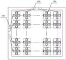
图1为本发明实施例触控面板的结构示意图。如图1所示,触控面板的主体结构包括多个力感单元100,多个力感单元100规则排布,形成M行*N列的矩阵图案,M、N为大于1的正整数。每个力感单元100通过扫描信号线200与扫描电路(未示出)连接,通过感应信号线300与感应电路(未示出)连接。工作时,扫描电路采用一定的帧频率以逐行扫描方式通过扫描信号线200依次向一行中的每个力感单元100输入扫描信号,感应电路通过感应信号线300采集该行的每一个力感单元100的感应信号,根据感应信号获知手指按压触控面板的触摸位置和施加在触摸位置的水平趋向力的方向和/或大小。FIG. 1 is a schematic structural diagram of a touch panel according to an embodiment of the present invention. As shown in FIG. 1 , the main structure of the touch panel includes a plurality of force-sensing
本发明实施例中,力感单元包括相对设置的第一基板和第二基板,其中,第一基板被配置为感知手指的水平趋向力,并在受到水平趋向力时,在水平趋向力的驱动下相对第二基板移动,以确定触摸位置和施加在触摸位置的水平趋向力的方向和/或大小。In the embodiment of the present invention, the force sensing unit includes a first substrate and a second substrate disposed opposite to each other, wherein the first substrate is configured to sense the horizontal tending force of the finger, and when subjected to the horizontal tending force, is driven by the horizontal tending force The lower portion is moved relative to the second substrate to determine the touch location and the direction and/or magnitude of the horizontal tending force applied at the touch location.
下面通过具体实施例详细说明本发明实施例的技术方案。The technical solutions of the embodiments of the present invention are described in detail below through specific embodiments.
第一实施例first embodiment
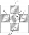
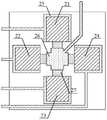
图2为本发明力感单元第一实施例的结构示意图,图3为图2结构的剖面示意图。如图2、图3所示,本实施例力感单元100的主体结构包括相对设置的触发基板10和传输基板20,触发基板10作为第一基板,用于承载手指按压并在手指施加水平趋向力的驱动下,相对传输基板20做少量的相对移动,实现驱动力触发。传输基板20作为第二基板,用于实现扫描信号和感应信号的传输。本实施例中,触发基板10朝向传输基板20一侧的表面上设置有一个感应电极11,传输基板20朝向触发基板10一侧的表面上设置有四个方向电极:第一方向电极21、第二方向电极22、第三方向电极23、第四方向电极24,传输基板20上的四个方向电极以感应电极11为中心对称设置,感应电极和方向电极均为柱状结构。作为一种示例,第一方向电极21和第三方向电极23分别位于感应电极11的上下两侧,第二方向电极22和第四方向电极24分别位于感应电极11的左右两侧,形成以感应电极11为中心的十字对称排布。同时,第一方向电极21通过第一扫描引出线Xm1、第二方向电极22通过第二扫描引出线Xm2、第三方向电极23通过第三扫描引出线Xm3、第四方向电极24通过第四扫描引出线Xm4,分别与扫描电路连接,感应电极11通过感应引出线Yn与感应电路连接。FIG. 2 is a schematic structural diagram of the force sensing unit according to the first embodiment of the present invention, and FIG. 3 is a cross-sectional schematic diagram of the structure of FIG. 2 . As shown in FIG. 2 and FIG. 3 , the main structure of the
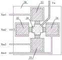
图4a和图4b为本发明力感单元第一实施例的工作原理图。本实施例力感单元的工作原理为,通过对四个方向电极输出恒定电压和采集一个感应电极的感应电压,来判断触摸位置以及触摸位置处感应电极的移动方向,进而判断触摸位置处所受水平趋向力的方向和大小。工作时,扫描电路通过第一扫描引出线Xm1向第一方向电极21施加第一电压信号U1,通过第二扫描引出线Xm2向第二方向电极22施加第二电压信号U2,通过第三扫描引出线Xm3向第三方向电极23施加第三电压信号U3,以及通过第四扫描引出线Xm4向第四方向电极24施加第四电压信号U4,其中,第一电压信号U1、第二电压信号U2、第三电压信号U3和第四电压信号U4的电压值不同。受四个方向电极电压信号的感应,感应电极11将生成相应的感应电压,感应电极11的感应电压由感应电路通过感应引出线Yn采集。4a and 4b are working principle diagrams of the first embodiment of the force sensing unit of the present invention. The working principle of the force sensing unit in this embodiment is to judge the touch position and the moving direction of the sensing electrode at the touch position by outputting constant voltages to the electrodes in four directions and collecting the sensing voltage of one sensing electrode, and then judge the impact on the touch position. The direction and magnitude of the horizontal trend force. During operation, the scanning circuit applies the first voltage signal U1 to the
当没有触摸时,感应电路采集到的每个力感单元的感应电压相同,而当有触摸发生时,触摸位置的力感单元的感应电压将发生改变,因此感应电路可以识别出感应电压发生变化的力感单元,由于扫描电路是采用一定帧频率的逐行扫描方式,因此感应电路根据感应电压发生变化力感单元的坐标即可确定触摸位置。When there is no touch, the induced voltage of each force-sensing unit collected by the sensing circuit is the same, and when there is a touch, the induced voltage of the force-sensing unit at the touch position will change, so the sensing circuit can recognize that the induced voltage has changed. Since the scanning circuit adopts a progressive scanning method with a certain frame frequency, the sensing circuit can determine the touch position according to the coordinates of the force sensing unit according to the change of the induced voltage.
当手指向触控面板施加垂直于触控面板表面的压力时(第一时刻),触摸位置处的感应电极11位于四个方向电极的中心,感应电极11产生感应电压U0,感应电路采集到感应电极11的感应电压U0后,可以得到感应电极11在该时刻的特征电压ΔU1、ΔU2、ΔU3和ΔU4,其中ΔU1=U1-U0,ΔU2=U2-U0,ΔU3=U3-U0,ΔU4=U4-U0,如图4a所示。When a finger applies pressure perpendicular to the touch panel surface (the first moment), the
当手指向触控面板施加平行于触控面板表面的水平趋向力时(第二时刻),在静摩擦力作用下,触摸位置的触发基板受该水平趋向力的驱动,会朝相同方向移动,进而带动触发基板上的感应电极11移动。例如,感应电极11偏离中心位置向第四方向电极24方向移动。因感应电极11的移动,其与四个方向电极的距离改变,其感应电压将从U0变为U0′。感应电路采集到感应电压U0′后,可以得到感应电极11在该时刻代表四个方向特征的特征电压ΔU1′、ΔU2′、ΔU3′和ΔU4′,其中ΔU1′=U1-U0′,ΔU2′=U2-U0′,ΔU3′=U3-U0′,ΔU4′=U4-U0′,如图4b所示。When a finger applies a horizontal directional force parallel to the surface of the touch panel (the second moment), under the action of static friction, the trigger substrate at the touch position is driven by the horizontal directional force to move in the same direction, and then Drive the
感应电路通过比较两个时刻的特征电压ΔU和ΔU′,即可判断出感应电极11的移动方向。具体地,根据电压感应原理,当感应电极11距离第四方向电极24的距离缩小时,感应电极11的感应电压将趋向于第四方向电极24的电压U4,即此时第四方向的特征电压ΔU4′将减小。同理,感应电极11距离其它三个方向电极的距离增大,三个方向的特征电压将增大。因此,感应电路通过比较ΔU1′与ΔU1、ΔU2′与ΔU2、ΔU3′与ΔU3和ΔU4′与ΔU4,即可以得到特征电压减小的ΔU4′,从而确定感应电极11的移动方向是朝向第四方向电极24的方向,进而判断感应电极11所受水平趋向力的方向是朝向第四方向电极24的方向。进一步地,通过ΔU4′与ΔU4之间差值的大小,还可以判断感应电极11所受水平趋向力的大小。The sensing circuit can determine the moving direction of the
根据前述的工作原理可以看出,本实施例力感单元不仅可以感知单一方向的水平趋势力,还可以感知旋转方向的水平趋势力。具体地,对于触摸手指位置不动但施加某一方向的水平趋势力时,在不同帧中,感应电路所判断的感应电极的移动方向是相同的。对于触摸手指位置不动但施加旋转方向的水平趋势力时,在不同帧中,感应电路所判断的感应电极的移动方向是变化的。例如,在第一时段的各个帧中,感应电路判断ΔU4′减小,在第二时段的各个帧中,感应电路判断ΔU3′减小,在第三时段的各个帧中,感应电路判断ΔU2′减小,在第四时段的各个帧中,感应电路判断ΔU1′减小,感应电路从而可以确定感应电极的移动方向分别是:第一时段朝向第四方向电极的方向,第二时段朝向第三方向电极的方向,第三时段朝向第二方向电极的方向,第四时段朝向第一方向电极的方向,进而可以判断感应电极所受水平趋向力的方向是旋转的,即触摸手指在触摸位置以顺时针方向揉搓。显然,用户不需要移动触摸位置即可表现出各种触摸状态,可以极大地丰富人机交互的多样性,将触控技术扩展到多维范畴。It can be seen from the foregoing working principle that the force sensing unit of this embodiment can sense not only the horizontal trend force in a single direction, but also the horizontal trend force in the rotation direction. Specifically, when the position of the touching finger does not move but a horizontal trend force in a certain direction is applied, in different frames, the moving directions of the sensing electrodes determined by the sensing circuit are the same. When the position of the touching finger does not move but the horizontal trend force in the rotation direction is applied, in different frames, the moving direction of the sensing electrode determined by the sensing circuit changes. For example, in each frame of the first period, the induction circuit judges that ΔU4' decreases, in each frame of the second period, the induction circuit judges that ΔU3' decreases, and in each frame of the third period, the induction circuit judges that ΔU2' In each frame of the fourth period, the induction circuit determines that ΔU1' decreases, and the induction circuit can determine that the moving directions of the induction electrodes are respectively: the first period is toward the direction of the electrode in the fourth direction, and the second period is toward the third direction. The direction of the direction electrode, the third period is toward the direction of the second direction electrode, and the fourth period is toward the direction of the first direction electrode, and then it can be judged that the direction of the horizontal trend force on the sensing electrode is rotating, that is, the touch finger at the touch position Knead in a clockwise direction. Obviously, users can express various touch states without moving the touch position, which can greatly enrich the diversity of human-computer interaction and expand touch technology to multi-dimensional categories.
图5a为本发明力感单元第一实施例触发基板的结构示意图,图5b为图5a结构的剖面示意图。如图5a和图5b所示,本实施例触发基板作为第一基板,主体结构包括设置在触发基底上柱状的感应电极11和薄膜状的润滑层12。其中,触发基底用于承载手指按压,并在手指施加的水平趋向力驱动下移动,并带动感应电极11移动,改变感应电极11与传输基板上四个方向电极之间的距离。在触发基板和传输基板对位扣合时,感应电极11位于四个方向电极之间,生成感应电压,润滑层12与传输基板上四个柱状的方向电极的顶端接触,用于减小触发基板与传输基板相对运动的摩擦力。5a is a schematic structural diagram of the trigger substrate of the force sensing unit according to the first embodiment of the present invention, and FIG. 5b is a cross-sectional schematic diagram of the structure of FIG. 5a. As shown in FIG. 5 a and FIG. 5 b , the trigger substrate in this embodiment is used as the first substrate, and the main structure includes a
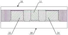
图6a为本发明力感单元第一实施例传输基板的结构示意图,图6b为图6a结构的剖面示意图。如图6a和图6b所示,本实施例传输基板作为第二基板,主体结构包括设置在传输基底上的扫描信号传输层25、感应信号传输层26、介质层27和绝缘层28,以及设置在扫描信号传输层25上柱状的四个方向电极:第一方向电极21、第二方向电极22、第三方向电极23和第四方向电极24。其中,薄膜状的扫描信号传输层25设置在传输基底上,包括四个扫描连接电极和四个扫描引出线(第一扫描引出线Xm1、第二扫描引出线Xm2、第三扫描引出线Xm3和第四扫描引出线Xm4),一个扫描连接电极连接一个扫描引出线。四个柱状的方向电极(第一方向电极21、第二方向电极22、第三方向电极23和第四方向电极24)分别设置在四个扫描连接电极上,使每个方向电极分别通过一个扫描连接电极和扫描引出线与扫描电路连接,分别接收扫描电路施加的电压信号。薄膜状的感应信号传输层26设置在传输基底上,包括相互连接的感应连接电极和感应引出线Yn,感应连接电极位于四个方向电极的中心,在触发基板和传输基板对位扣合时,感应连接电极与触发基板的柱状的感应电极11的顶端连接,使感应电极11生成的感应电压通过感应连接电极和感应引出线传输给感应电路。介质层27设置在传输基底上,包括四个柱状的介质块,分别设置在感应连接电极与四个方向电极之间,在触发基板和传输基板对位扣合时,四个介质块分别设置在感应电极11与四个方向电极之间。介质层27用于隔离感应电极与方向电极,并提供使感应电极11复位的回复力。由于介质层设置在感应电极与方向电极之间,因此当感应电极移动时,相应位置的介质块被压缩。当驱动感应电极移动的水平趋向力消失时,被压缩的介质块在弹性作用下恢复原形状,弹性回复力推动感应电极复位,使感应电极返回中心位置。绝缘层28设置在传输基底上,设置在四个方向电极的外围,用于力感单元之间的绝缘。6a is a schematic structural diagram of the transmission substrate of the first embodiment of the force sensing unit of the present invention, and FIG. 6b is a cross-sectional schematic diagram of the structure of FIG. 6a. As shown in FIG. 6a and FIG. 6b, the transmission substrate in this embodiment is used as the second substrate, and the main structure includes a scanning
下面通过力感单元的制备过程进一步说明本实施例的技术方案。其中,本实施例中所说的“构图工艺”包括沉积膜层、涂覆光刻胶、掩模曝光、显影、刻蚀、剥离光刻胶等处理,是现有成熟的制备工艺。沉积可采用溅射、蒸镀、化学气相沉积等已知工艺,涂覆可采用已知的涂覆工艺,刻蚀可采用已知的方法,在此不做具体的限定。The technical solution of this embodiment is further described below through the preparation process of the force sensing unit. Among them, the "patterning process" mentioned in this embodiment includes processes such as depositing a film layer, coating photoresist, mask exposure, developing, etching, and stripping photoresist, which is an existing mature preparation process. The deposition can use known processes such as sputtering, evaporation, and chemical vapor deposition, the coating can use a known coating process, and the etching can use a known method, which is not specifically limited here.
本发明实施例触控面板的制备过程主要包括:(1)分别制备触发基板和传输基板;(2)将触发基板和传输基板对位扣合。The manufacturing process of the touch panel according to the embodiment of the present invention mainly includes: (1) preparing a trigger substrate and a transmission substrate respectively; (2) aligning and snapping the trigger substrate and the transmission substrate.
制备触发基板的过程包括:依次在触发基底上形成润滑层和感应电极。其中,形成润滑层可以包括,在触发基底上涂覆一层润滑薄膜,采用单色调掩膜版对润滑薄膜进行曝光并显影,形成润滑层图案。形成感应电极包括,在触发基底上沉积一金属薄膜,在金属薄膜上涂覆一层光刻胶,采用单色调掩膜版对光刻胶进行曝光并显影,在感应电极图案位置形成未曝光区域,保留有光刻胶,在其它位置形成完全曝光区域,光刻胶被去除,对完全曝光区域的金属薄膜进行刻蚀并剥离剩余的光刻胶,形成柱状的感应电极图案,如图5a和图5b所示。本实施例中,形成润滑层和感应电极的次序也可以是先形成感应电极,后形成润滑层,在此不做具体限定。其中,润滑层的厚度为50~150μm,感应电极的厚度为550~850μm。The process of preparing the triggering substrate includes: sequentially forming a lubricating layer and a sensing electrode on the triggering substrate. Wherein, forming the lubricating layer may include coating a layer of lubricating film on the trigger substrate, and exposing and developing the lubricating film by using a monochromatic mask to form a lubricating layer pattern. Forming the sensing electrode includes depositing a metal film on the trigger substrate, coating a layer of photoresist on the metal film, exposing and developing the photoresist using a single-tone mask, and forming an unexposed area at the position of the sensing electrode pattern , the photoresist is retained, a fully exposed area is formed in other positions, the photoresist is removed, the metal film in the fully exposed area is etched and the remaining photoresist is peeled off to form a columnar sensing electrode pattern, as shown in Figure 5a and shown in Figure 5b. In this embodiment, the order of forming the lubricating layer and the sensing electrode may also be that the sensing electrode is formed first, and then the lubricating layer is formed, which is not specifically limited herein. The thickness of the lubricating layer is 50-150 μm, and the thickness of the induction electrode is 550-850 μm.
制备传输基板的过程包括:先形成扫描信号传输层和感应信号传输层图案,后形成方向电极图案,最后形成介质层和绝缘层图案。图7a~图10为本发明传输基板制备过程的示意图。The process of preparing the transmission substrate includes: firstly forming the pattern of the scanning signal transmission layer and the sensing signal transmission layer, then forming the directional electrode pattern, and finally forming the pattern of the dielectric layer and the insulating layer. 7a to 10 are schematic diagrams of the preparation process of the transmission substrate of the present invention.
首先,在传输基底上形成扫描信号传输层和感应信号传输层图案。形成扫描信号传输层和感应信号传输层图案包括:在传输基底上沉积一透明导电薄膜,在透明导电薄膜上涂覆一层光刻胶,采用单色调掩膜版对光刻胶进行曝光并显影,在扫描信号传输层和感应信号传输层图案位置形成未曝光区域,保留有光刻胶,在其它位置形成完全曝光区域,光刻胶被去除,对完全曝光区域的透明导电薄膜进行刻蚀并剥离剩余的光刻胶,形成扫描信号传输层25和感应信号传输层26图案,如图7a和图7b所示。其中,扫描信号传输层25图案包括四个扫描连接电极图案和四个扫描引出线图案,一个扫描连接电极连接一个扫描引出线,感应信号传输层26图案包括相互连接的感应连接电极图案和感应引出线图案,感应连接电极位于四个扫描连接电极中心。其中,扫描信号传输层25和感应信号传输层26的厚度为50~150μm。First, a scanning signal transmission layer and an inductive signal transmission layer pattern are formed on a transmission substrate. Forming the pattern of the scanning signal transmission layer and the sensing signal transmission layer includes: depositing a transparent conductive film on the transmission substrate, coating a layer of photoresist on the transparent conductive film, and exposing and developing the photoresist by using a single-tone mask , an unexposed area is formed at the pattern positions of the scanning signal transmission layer and the sensing signal transmission layer, the photoresist is retained, a fully exposed area is formed at other positions, the photoresist is removed, and the transparent conductive film in the fully exposed area is etched and The remaining photoresist is peeled off to form patterns of the scanning
其次,形成方向电极图案。形成方向电极图案包括:在形成前述图案的传输基底上,沉积一金属薄膜,在金属薄膜上涂覆一层光刻胶,采用单色调掩膜版对光刻胶进行曝光并显影,在方向电极图案位置形成未曝光区域,保留有光刻胶,在其它位置形成完全曝光区域,光刻胶被去除,对完全曝光区域的金属薄膜进行刻蚀并剥离剩余的光刻胶,形成柱状的方向电极图案,如图8a和图8b所示。其中,四个方向电极(第一方向电极21、第二方向电极22、第三方向电极23和第四方向电极24)分别设置在四个扫描连接电极上,四个方向电极的厚度为500~800μm。Next, directional electrode patterns are formed. Forming the directional electrode pattern includes: depositing a metal film on the transmission substrate on which the aforementioned pattern is formed, coating a layer of photoresist on the metal film, exposing and developing the photoresist by using a monochromatic mask, and applying a single-tone mask to the photoresist. An unexposed area is formed at the pattern position, and the photoresist is retained. A fully exposed area is formed in other positions. The photoresist is removed. The metal film in the fully exposed area is etched and the remaining photoresist is peeled off to form a columnar directional electrode. pattern, as shown in Figures 8a and 8b. Among them, four direction electrodes (the
再次,形成介质层图案。形成介质层图案包括:在形成前述图案的传输基底上,涂覆一层介质薄膜,采用单色调掩膜版对介质薄膜进行曝光并显影,形成介质层27图案,如图9a和图9b所示。其中,介质层27图案包括四个介质块,分别设置在感应连接电极与每个方向电极之间,介质层27的厚度为600~900μm,介质层27图案上表面距离传输基底上表面的距离,大于方向电极图案上表面距离传输基底上表面的距离,以便于在触发基板和传输基板对位扣合时,四个介质块隔离感应电极与方向电极。Again, a dielectric layer pattern is formed. Forming the pattern of the dielectric layer includes: coating a layer of dielectric film on the transmission substrate on which the aforementioned pattern is formed, and exposing and developing the dielectric film with a single-tone mask to form a pattern of the
最后,形成绝缘层图案。形成绝缘层图案包括:在形成前述图案的传输基底上,涂覆一层绝缘薄膜,采用单色调掩膜版对绝缘薄膜进行曝光并显影,形成绝缘层28图案,如图10所示。其中,绝缘层28图案位于四个方向电极的外侧,厚度为600~900μm,绝缘层28图案上表面距离传输基底上表面的距离,大于方向电极图案上表面距离传输基底上表面的距离,以便于在触发基板和传输基板对位扣合时,形成力感单元之间的绝缘隔离。Finally, an insulating layer pattern is formed. Forming the insulating layer pattern includes: coating a layer of insulating film on the transmission substrate on which the pattern is formed, exposing and developing the insulating film with a single-tone mask to form a pattern of the insulating
其中,传输基底可以采用玻璃基底或石英基底,触发基底可以采用塑料或聚合物材料的柔性基底,扫描信号传输层可以采用氧化铟锡ITO或氧化铟锌IZO,感应信号传输层可以采用耐磨的导电材料,也可以采用ITO或IZO,方向电极和感应电极可以采用铂Pt、钌Ru、金Au、银Ag、钼Mo、铬Cr、铝Al、钽Ta、钛Ti、钨W等金属中的一种或多种,润滑层可以采用聚四氟乙烯PTFE,介质层可以采用具有一定弹性的材料,绝缘层可以采用树脂材料。Among them, the transmission substrate can be glass substrate or quartz substrate, the trigger substrate can be flexible substrate of plastic or polymer material, the scanning signal transmission layer can be indium tin oxide ITO or indium zinc oxide IZO, the sensing signal transmission layer can be wear-resistant Conductive materials, ITO or IZO can also be used, direction electrodes and sensing electrodes can be made of platinum Pt, ruthenium Ru, gold Au, silver Ag, molybdenum Mo, chromium Cr, aluminum Al, tantalum Ta, titanium Ti, tungsten W and other metals. One or more, the lubricating layer can be made of polytetrafluoroethylene PTFE, the dielectric layer can be made of a material with certain elasticity, and the insulating layer can be made of resin material.
在实际实施时,扫描信号传输层和感应信号传输层图案也可以采用两次工艺分别形成,使得制备扫描信号传输层的材料和制备感应信号传输层的材料不同。例如,扫描信号传输层采用氧化铟锡ITO或氧化铟锌IZO,感应信号传输层采用耐磨的导电材料。In actual implementation, the patterns of the scanning signal transmission layer and the sensing signal transmission layer can also be formed by two processes respectively, so that the materials for preparing the scanning signal transmission layer and the materials for preparing the sensing signal transmission layer are different. For example, the scanning signal transmission layer adopts indium tin oxide ITO or indium zinc oxide IZO, and the sensing signal transmission layer adopts wear-resistant conductive material.
在完成触发基板和传输基板的制备后,进行对位扣合工艺形成触控面板。在一个实施例中,如果触发基底采用较硬的材料,可以采用组合形式的触发基板,将触发基板划分为多个触发基板单元,每个触发基板单元之间具有设定的间距,以保证当某个触发基板单元在手指施加的水平趋向力的驱动下移动时,不会影响其它触发基板单元。实际实施时,可以参照现有触摸电极的尺寸设计触发基板单元的大小。例如,触发基板单元可以设计成大小约为4*4mm或5*5mm的矩形,每个触发基板单元包括多个规则排列的力感单元。对位扣合处理中,先将多个触发基板单元依次对位扣设在传输基板上,然后通过封装层30将触发基板和传输基板封装为一体,如图11所示。其中,封装层30可以采用耐磨塑料膜粘接封装方式,覆盖多个触发基板单元,并通过触发基板单元之间间隙和周边区域与传输基板粘接,形成触发基板粘附于传输基板且不会分离的完整的触控面板。在另一个实施例中,如果触发基底采用柔性材料,则可以采用整体的触发基板,利用柔性也可以保证仅触摸位置区域的触发基板移动。After the preparation of the trigger substrate and the transmission substrate is completed, the touch panel is formed by an alignment and snap-fit process. In one embodiment, if the trigger base is made of a harder material, a combined trigger base can be used, and the trigger base is divided into a plurality of trigger base units, and each trigger base unit has a set distance to ensure that when When a certain trigger substrate unit moves under the driving of the horizontal directional force applied by the finger, it will not affect other trigger substrate units. In actual implementation, the size of the trigger substrate unit can be designed with reference to the size of the existing touch electrodes. For example, the trigger substrate unit can be designed into a rectangle with a size of about 4*4mm or 5*5mm, and each trigger substrate unit includes a plurality of regularly arranged force sensing units. In the alignment and buckle process, a plurality of trigger substrate units are sequentially aligned and buckled on the transmission substrate, and then the trigger substrate and the transmission substrate are packaged into one through the
实际实施时,本实施例的触控面板可以与显示面板结合起来,作为触控显示面板。图12为本发明触控显示面板的结构示意图,如图12所示,触控显示面板的主体结构包括触控面板1和显示面板2,触控面板1设置在显示面板2的出光面上,通过贴合胶3固定。显示面板可以是液晶(Liquid Crystal Display,LCD)面板,也可以是有机发光二极管(OrganicLight Emitting Diode,OLED)面板,还可以是其它平板显示器。In actual implementation, the touch panel of this embodiment may be combined with a display panel to serve as a touch display panel. FIG. 12 is a schematic structural diagram of the touch display panel of the present invention. As shown in FIG. 12 , the main structure of the touch display panel includes a touch panel 1 and a display panel 2 , and the touch panel 1 is disposed on the light emitting surface of the display panel 2 . Secured with adhesive 3. The display panel may be a liquid crystal (Liquid Crystal Display, LCD) panel, may also be an organic light emitting diode (Organic Light Emitting Diode, OLED) panel, or may be other flat panel displays.
本实施例所提供的力感单元,通过相对设置的第一基板和第二基板,使得第一基板在受到水平趋向力时相对第二基板移动,不仅可以识别触摸位置,而且可以感知作用在触摸位置的水平趋势力。通过感知所施加的水平趋势力,可以识别用户的触控意向,使用户不用移动手指即可实现触控操作,极大地丰富人机交互的多样性,将触控技术扩展到多维范畴。The force-sensing unit provided in this embodiment, through the first substrate and the second substrate disposed opposite to each other, makes the first substrate move relative to the second substrate when subjected to a horizontal trend force, which can not only identify the touch position, but also sense the impact on the touch. The horizontal trend force of the position. By sensing the applied horizontal trend force, the user's touch intention can be identified, so that the user can realize the touch operation without moving the finger, which greatly enriches the diversity of human-computer interaction and extends the touch technology to the multi-dimensional category.
第二实施例Second Embodiment
本实施例是基于第一实施例的一种扩展,与第一实施例不同的是,本实施例方向电极设置在触发基板上,感应电极设置在传输基板上。图13为本发明力感单元第二实施例的结构示意图,如图13所示,本实施例触发基板10作为第一基板,主体结构包括设置在触发基底上柱状的四个方向电极21、22、23和24,传输基板20作为第二基板,主体结构包括设置在传输基底上的扫描信号传输层25、感应信号传输层26以及设置在感应信号传输层26上柱状的感应电极11。在触发基板10和传输基板20对位扣合时,触发基底10上的四个柱状方向电极的顶端与传输基底20上的扫描信号传输层紧密接触,接收扫描电路通过扫描引出线输入的电压信号,感应电极11邻近触发基板10的端部可以悬空,也可以与触发基板上的润滑层接触。介质层和绝缘层可以设置在触发基板10,也可以设置在传输基板20上。虽然本实施例结构是感应电极固定,四个方向电极随触发基板移动,但判断水平趋向力方向和大小的原理与第一实施例相同。This embodiment is an extension based on the first embodiment. The difference from the first embodiment is that the directional electrodes are arranged on the trigger substrate and the sensing electrodes are arranged on the transmission substrate. FIG. 13 is a schematic structural diagram of the second embodiment of the force sensing unit of the present invention. As shown in FIG. 13 , the
在实际实施时,第一实施例的结构还可以实现多种类似的扩展。例如,介质层可以设置在触发基底上。又如,感应信号传输层可以设置在触发基底上,感应电极设置在感应连接电极上,通过感应连接电极和感应引出线与感应电路连接。再如,扫描信号传输层和感应信号传输层均设置在触发基底上等等。In actual implementation, the structure of the first embodiment can also achieve a variety of similar extensions. For example, a dielectric layer may be disposed on the trigger substrate. For another example, the inductive signal transmission layer may be disposed on the trigger substrate, the inductive electrode may be disposed on the inductive connection electrode, and connected to the inductive circuit through the inductive connection electrode and the inductive lead wire. For another example, the scanning signal transmission layer and the sensing signal transmission layer are both disposed on the trigger substrate, and so on.
第三实施例Third Embodiment
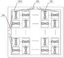
虽然前述实施例以一个力感单元包括4个方向电极为例进行了说明,但实际实施时,一个力感单元中方向电极的数量可以根据相关需要进行设计,方向电极的数量可以为2~8个。在精度要求较高时,可以增加方向电极的数量,如6个或8个,在精度要求较低时,可以减少方向电极的数量,如2个或3个。图14为本发明力感单元第三实施例的结构示意图,如图14所示,本实施例触控面板包括规则排布的多个触发基板单元100A,每个触发基板单元100A的大小约为4*4mm或5*5mm的矩形。其中,每个触发基板单元100A包括多个规则排布的力感单元100,每个力感单元100包括1个感应电极和2个方向电极,2个方向电极以感应电极为中心对称设置,但不同力感单元100中方向电极的排列方向不同。例如,一部分方向电极为左右排列,另一部分方向电极为上下排列,两者排列方向相互垂直。通过该种布局设计,2个方向电极左右排列的力感单元可以感知左右方向的水平趋势力,2个方向电极上下排列的力感单元可以感知上下方向的水平趋势力,从而实现一个触发基板单元可以感知多方向的水平趋势力。本实施例这种设计,可以有效减少扫描引出线的数量,简化触控面板的结构。Although the foregoing embodiment is described by taking a force sensing unit including 4 directional electrodes as an example, in actual implementation, the number of directional electrodes in a force sensing unit can be designed according to relevant needs, and the number of directional electrodes can be 2-8 indivual. When the accuracy requirements are high, the number of direction electrodes can be increased, such as 6 or 8, and when the accuracy requirements are low, the number of direction electrodes can be reduced, such as 2 or 3. FIG. 14 is a schematic structural diagram of the third embodiment of the force sensing unit of the present invention. As shown in FIG. 14 , the touch panel of this embodiment includes a plurality of
第四实施例Fourth Embodiment
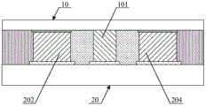
图15为本发明力感单元第四实施例的结构示意图,图16为图15结构的剖面示意图。如图15、图16所示,本实施例力感单元的主体结构包括相对设置的触发基板10和传输基板20,触发基板10作为第一基板,用于承载手指按压并在手指施加水平趋向力的驱动下,相对传输基板20做少量的相对移动,实现驱动力触发。传输基板20作为第二基板,用于实现扫描信号和感应信号的传输。FIG. 15 is a schematic structural diagram of the fourth embodiment of the force sensing unit of the present invention, and FIG. 16 is a cross-sectional schematic diagram of the structure of FIG. 15 . As shown in FIG. 15 and FIG. 16 , the main structure of the force sensing unit in this embodiment includes a
本实施例中,触发基板10上设置有一个柱状的方向电极101,传输基板20上设置有四个柱状的感应电极:第一感应电极201、第二感应电极202、第三感应电极203和第四感应电极204,传输基板20上的四个感应电极以方向电极101为中心对称设置。例如,第一感应电极201和第三感应电极203分别位于方向电极101的上下两侧,第二感应电极202和第四感应电极204分别位于方向电极101的左右两侧,形成以方向电极101为中心的十字对称排布。同时,方向电极101通过扫描引出线Xm与扫描电路连接,第一感应电极201通过第一感应引出线Yn1、第二感应电极202通过第二感应引出线Yn2、第三感应电极203通过第三感应引出线Yn3、第四感应电极204通过第四感应引出线Yn4,分别与感应电路连接。In this embodiment, the
本实施例力感单元的工作原理为,通过对一个方向电极输出恒定电压和采集四个感应电极的感应电压,来判断触摸位置以及触摸位置处方向电极的移动方向,进而判断触摸位置处所受水平趋向力的方向和大小。工作时,扫描电路通过扫描引出线Xm向方向电极101施加电压信号,受方向电极电压信号的感应,四个感应电极将产生出相应的感应电压,感应电路通过第一感应引出线Yn1采集第一感应电极201的感应电压,通过第二感应引出线Yn2采集第二感应电极202的感应电压,通过第三感应引出线Yn3采集第三感应电极203的感应电压,通过第四感应引出线Yn4采集第四感应电极204的感应电压。The working principle of the force-sensing unit in this embodiment is to determine the touch position and the moving direction of the direction electrodes at the touch position by outputting a constant voltage to one direction electrode and collecting the induced voltages of the four sensing electrodes, and then to determine the affected position at the touch position. The direction and magnitude of the horizontal trend force. During operation, the scanning circuit applies a voltage signal to the
当没有触摸时,感应电路采集到的每个力感单元的感应电压相同,而当有触摸发生时,触摸位置的力感单元的感应电压将发生改变,因此感应电路可以识别出感应电压发生变化的力感单元,由于扫描电路是采用一定帧频率的逐行扫描方式,因此感应电路根据感应电压发生变化力感单元的坐标即可确定触摸位置。When there is no touch, the induced voltage of each force-sensing unit collected by the sensing circuit is the same, and when there is a touch, the induced voltage of the force-sensing unit at the touch position will change, so the sensing circuit can recognize that the induced voltage has changed. Since the scanning circuit adopts a progressive scanning method with a certain frame frequency, the sensing circuit can determine the touch position according to the coordinates of the force sensing unit according to the change of the induced voltage.
当手指向触控面板施加垂直于触控面板表面的压力时(第一时刻),由于触摸位置处的四个感应电极以方向电极为中心对称设置,因此四个感应电极的感应电压相同。当手指向触控面板施加平行于触控面板表面的水平趋向力时(第二时刻),在静摩擦力作用下,触摸位置的触发基板受该水平趋向力的驱动,会朝相同方向移动,进而带动触发基板上的方向电极101移动。例如,方向电极101偏离中心位置向第四感应电极204方向移动。因方向电极101的移动,其与四个感应电极的距离改变,每个感应电极的感应电压将发生变化。感应电路采集到四个感应电压后,通过比较四个感应电压,即可判断出方向电极101的移动方向。When the finger applies pressure perpendicular to the touch panel surface (the first moment), since the four sensing electrodes at the touch position are symmetrically arranged around the direction electrode, the induced voltages of the four sensing electrodes are the same. When a finger applies a horizontal directional force parallel to the surface of the touch panel (the second moment), under the action of static friction, the trigger substrate at the touch position is driven by the horizontal directional force to move in the same direction, and then The direction electrode 101 on the trigger substrate is driven to move. For example, the
具体地,根据感应电压的原理,当方向电极101距离第四感应电极204的距离缩小时,第四感应电极204的感应电压将趋向于方向电极101的电压。同理,方向电极101距离其它三个感应电极的距离增大,三个感应电极的感应电压将减小。因此,感应电路通过比较四个感应电压,即可以确定感应电压增大的感应电极,从而确定方向电极101的移动方向是朝向第四感应电极204的方向,进而判断感应电极11所受水平趋向力的方向是朝向第四感应电极204的方向。进一步地,通过感应电压增大的程度,还可以判断水平趋向力的大小。Specifically, according to the principle of induced voltage, when the distance between the
图17a为本发明力感单元第四实施例触发基板的结构示意图,图17b为图17a结构的剖面示意图。如图17a和图17b所示,本实施例触发基板作为第一基板,主体结构包括设置在触发基底上柱状的方向电极101和薄膜状的润滑层12。其中,触发基底用于承载手指按压,并在手指施加的水平趋向力驱动下移动,并带动方向电极101移动,改变方向电极101与传输基板上四个感应电极之间的距离。在触发基板和传输基板对位扣合时,方向电极101位于四个感应电极之间,用于使四个感应电极分别生成感应电压,润滑层12与四个方向感应接触,用于减小触发基板与传输基板相对运动的摩擦力。17a is a schematic structural diagram of a trigger substrate of a fourth embodiment of the force sensing unit of the present invention, and FIG. 17b is a cross-sectional schematic diagram of the structure of FIG. 17a. As shown in FIG. 17a and FIG. 17b, the trigger substrate in this embodiment is used as the first substrate, and the main structure includes a columnar
图18a为本发明力感单元第四实施例传输基板的结构示意图,图18b为图18a结构的剖面示意图。如图18a和图18b所示,本实施例传输基板作为第二基板,主体结构包括设置在传输基底上的扫描信号传输层25、感应信号传输层26、介质层27和绝缘层28,以及设置在感应信号传输层26上柱状的四个感应电极:第一感应电极201、第二感应电极202、第三感应电极203和第四感应电极204。其中,薄膜状的扫描信号传输层25设置在传输基底上,包括相互连接的扫描连接电极和扫描引出线Xm,扫描连接电极位于四个感应电极的中心,在触发基板和传输基板对位扣合时,扫描连接电极与触发基板的方向电极101连接,使方向电极101通过扫描连接电极和扫描引出线Xm与扫描电路连接,接收扫描电路施加的电压信号。薄膜状的感应信号传输层26设置在传输基底上,包括四个感应连接电极和四个感应引出线(第一感应引出线Yn1、第二感应引出线Yn2、第三感应引出线Yn3和第四感应引出线Yn4),一个感应连接电极连接一个感应引出线。四个柱状的感应电极(第一感应电极201、第二感应电极202、第三感应电极203和第四感应电极204)分别设置在四个感应连接电极上,使每个感应电极分别通过一个感应连接电极和感应引出线与感应电路连接,每个感应电极生成的感应电压通过一个感应连接电极和一个感应引出线传输给感应电路。介质层27设置在传输基底上,包括四个介质块,在触发基板和传输基板对位扣合时,四个介质块分别设置在方向电极与四个感应电极之间。绝缘层28设置在传输基底上,设置在四个感应电极的外围。其中,润滑层12、介质层27和绝缘层28的作用与前述实施例相同,这里不再赘述。18a is a schematic structural diagram of the transmission substrate of the fourth embodiment of the force sensing unit of the present invention, and FIG. 18b is a cross-sectional schematic diagram of the structure of FIG. 18a. As shown in FIG. 18a and FIG. 18b, the transmission substrate in this embodiment is used as the second substrate, and the main structure includes a scanning
本实施例力感单元的制备过程与前述第一实施例相近,主要包括:(1)分别制备触发基板和传输基板;(2)将触发基板和传输基板对位扣合。其中,制备触发基板的过程包括:依次在触发基底上形成润滑层和方向电极。制备传输基板的过程包括:先形成扫描信号传输层和感应信号传输层图案,后形成四个感应电极图案,最后形成介质层和绝缘层图案。对位扣合工艺、各膜层的材料、厚度等与前述实施例相同,这里不再赘述。The preparation process of the force sensing unit in this embodiment is similar to that in the first embodiment, and mainly includes: (1) preparing the triggering substrate and the transmission substrate respectively; (2) aligning the triggering substrate and the transmission substrate together. Wherein, the process of preparing the triggering substrate includes: sequentially forming a lubricating layer and a direction electrode on the triggering substrate. The process of preparing the transmission substrate includes: firstly forming the pattern of the scanning signal transmission layer and the sensing signal transmission layer, then forming four sensing electrode patterns, and finally forming the pattern of the dielectric layer and the insulating layer. The alignment and fastening process, the material and thickness of each film layer, etc. are the same as those in the previous embodiment, and will not be repeated here.
第五实施例Fifth Embodiment
本实施例是基于第四实施例的一种扩展,与第四实施例不同的是,本实施例四个感应电极设置在触发基板上,一个方向电极设置在传输基板上。此外,本实施例的结构还可以实现多种类似的扩展。例如,介质层可以设置在触发基底上。又如,感应信号传输层可以设置在触发基底上。再如,扫描信号传输层和感应信号传输层均设置在触发基底上等等。相关结构可以参见前述实施例,这里不再赘述。进一步地,本实施例的力感单元可以包括2个感应电极和1个方向电极,2个感应电极以方向电极为中心对称设置,但不同力感单元中感应电极的排列方向不同。相关结构可以参见前述实施例,这里不再赘述。This embodiment is an extension based on the fourth embodiment. The difference from the fourth embodiment is that in this embodiment, four sensing electrodes are arranged on the trigger substrate, and one direction electrode is arranged on the transmission substrate. In addition, the structure of this embodiment can also implement a variety of similar extensions. For example, a dielectric layer may be disposed on the trigger substrate. For another example, the sensing signal transmission layer may be disposed on the trigger substrate. For another example, the scanning signal transmission layer and the sensing signal transmission layer are both disposed on the trigger substrate, and so on. For the related structure, reference may be made to the foregoing embodiments, which will not be repeated here. Further, the force sensing unit of this embodiment may include two sensing electrodes and one directional electrode. The two sensing electrodes are symmetrically arranged around the directional electrode, but the sensing electrodes are arranged in different directions in different force sensing units. For the related structure, reference may be made to the foregoing embodiments, which will not be repeated here.
第六实施例Sixth Embodiment
基于前述实施例的技术方案,本实施例提供了一种力感单元的制备方法,包括:Based on the technical solutions of the foregoing embodiments, the present embodiment provides a method for preparing a force sensing unit, including:
S1、分别制备第一基板和第二基板;S1, prepare the first substrate and the second substrate respectively;
S2、将所述第一基板和第二基板对位扣合,使所述第一基板在受到水平趋向力时相对所述第二基板移动,以感知所述水平趋向力的方向和/或大小。S2. Align the first substrate and the second substrate, so that the first substrate moves relative to the second substrate when subjected to a horizontal tending force, so as to sense the direction and/or magnitude of the horizontal tending force .
其中,步骤S1包括:制备包括一个感应电极的第一基板,制备包括多个方向电极的第二基板。Wherein, step S1 includes: preparing a first substrate including one sensing electrode, and preparing a second substrate including a plurality of directional electrodes.
制备感应电极和方向电极均采用构图工艺,第一基板和第二基板的制备次序可以根据实际需要任意安排。A patterning process is used to prepare the sensing electrodes and the direction electrodes, and the preparation sequence of the first substrate and the second substrate can be arbitrarily arranged according to actual needs.
其中,制备包括一个感应电极的第一基板,包括:Wherein, preparing a first substrate including one sensing electrode, including:
在基底上形成用于减小第一基板与第二基板相对运动摩擦力的润滑层和柱状的感应电极。A lubricating layer and a columnar induction electrode are formed on the base for reducing the frictional force of the relative motion of the first substrate and the second substrate.
润滑层和感应电极的制备次序可以根据实际需要任意安排。The preparation sequence of the lubricating layer and the induction electrode can be arbitrarily arranged according to actual needs.
其中,制备包括多个方向电极的第二基板,包括:Wherein, preparing a second substrate including a plurality of directional electrodes, including:
形成扫描信号传输层和感应信号传输层;在所述扫描信号传输层上形成多个柱状的方向电极;形成介质层和绝缘层。forming a scanning signal transmission layer and an induction signal transmission layer; forming a plurality of columnar directional electrodes on the scanning signal transmission layer; forming a dielectric layer and an insulating layer.
其中,步骤S1包括:将所述第一基板和第二基板制备有电极的表面相对并对位扣合,所述多个方向电极以所述感应电极为中心对称设置,使所述感应电极在第一基板相对第二基板移动时,通过感知所述感应电极与方向电极之间的距离,确定触摸位置和施加在触摸位置的水平趋向力的方向和/或大小。Wherein, step S1 includes: the surfaces of the first substrate and the second substrate on which electrodes are prepared face each other and snap together, and the plurality of directional electrodes are symmetrically arranged around the sensing electrode, so that the sensing electrode is located at the center of the sensing electrode. When the first substrate moves relative to the second substrate, the touch position and the direction and/or magnitude of the horizontal force applied to the touch position are determined by sensing the distance between the sensing electrode and the direction electrode.
本实施例中,步骤S1还可以是:制备包括多个方向电极的第一基板,制备包括一个感应电极的第二基板;或者,制备包括一个方向电极的第一基板,制备包括多个感应电极的第二基板;或者,制备包括多个感应电极的第一基板,制备包括一个方向电极的第二基板。In this embodiment, step S1 may also be: preparing a first substrate including a plurality of directional electrodes, and preparing a second substrate including a sensing electrode; or, preparing a first substrate including a directional electrode, preparing a plurality of sensing electrodes or, prepare a first substrate including a plurality of sensing electrodes, and prepare a second substrate including one directional electrode.
第七实施例Seventh Embodiment
基于前述实施例的技术方案,本实施例还提供了一种触控面板的驱动方法。触控面板采用前述实施例的触控面板,主体结构包括扫描电路、感应电路以及矩阵排布的多个力感单元,每个力感单元包括方向电极和感应电极,扫描电路与每个力感单元的方向电极连接,感应电路与每个力感单元的感应电极连接。本实施例触控面板的驱动方法包括:Based on the technical solutions of the foregoing embodiments, this embodiment further provides a driving method of a touch panel. The touch panel adopts the touch panel of the previous embodiment, and the main structure includes a scanning circuit, a sensing circuit, and a plurality of force-sensing units arranged in a matrix. The direction electrodes of the units are connected, and the induction circuit is connected to the induction electrodes of each force-sensing unit. The driving method of the touch panel in this embodiment includes:
扫描电路以逐行扫描方式向一行中每个力感单元的方向电极输入电压信号;The scanning circuit inputs a voltage signal to the direction electrode of each force-sensing unit in a row in a line-by-line scanning manner;
感应电路实时采集该行中每个力感单元的感应电极的感应电压,根据所述感应电压确定触摸位置和施加在触摸位置的水平趋向力的方向和/或大小。The sensing circuit collects the sensing voltage of the sensing electrodes of each force-sensing unit in the row in real time, and determines the touch position and the direction and/or magnitude of the horizontal trend force applied to the touch position according to the sensing voltage.
在本发明实施例的描述中,需要理解的是,术语“中部”、“上”、“下”、“前”、“后”、“竖直”、“水平”、“顶”、“底”“内”、“外”等指示的方位或位置关系为基于附图所示的方位或位置关系,仅是为了便于描述本发明和简化描述,而不是指示或暗示所指的装置或元件必须具有特定的方位、以特定的方位构造和操作,因此不能理解为对本发明的限制。In the description of the embodiments of the present invention, it should be understood that the terms "middle", "upper", "lower", "front", "rear", "vertical", "horizontal", "top", "bottom" "The orientation or positional relationship indicated by "inside", "outside", etc. is based on the orientation or positional relationship shown in the drawings, and is only for the convenience of describing the present invention and simplifying the description, rather than indicating or implying that the indicated device or element must be It has a specific orientation, is constructed and operates in a specific orientation, and therefore should not be construed as a limitation of the present invention.
在本发明实施例的描述中,需要说明的是,除非另有明确的规定和限定,术语“安装”、“相连”、“连接”应做广义理解,例如,可以是固定连接,也可以是可拆卸连接,或一体地连接;可以是机械连接,也可以是电连接;可以是直接相连,也可以通过中间媒介间接相连,可以是两个元件内部的连通。对于本领域的普通技术人员而言,可以具体情况理解上述术语在本发明中的具体含义。In the description of the embodiments of the present invention, it should be noted that the terms "installed", "connected" and "connected" should be understood in a broad sense, unless otherwise expressly specified and limited. For example, it may be a fixed connection or a Removable connection, or integral connection; can be mechanical connection, can also be electrical connection; can be directly connected, can also be indirectly connected through an intermediate medium, can be internal communication between two components. For those of ordinary skill in the art, the specific meanings of the above terms in the present invention can be understood in specific situations.
虽然本发明所揭露的实施方式如上,但所述的内容仅为便于理解本发明而采用的实施方式,并非用以限定本发明。任何本发明所属领域内的技术人员,在不脱离本发明所揭露的精神和范围的前提下,可以在实施的形式及细节上进行任何的修改与变化,但本发明的专利保护范围,仍须以所附的权利要求书所界定的范围为准。Although the embodiments disclosed in the present invention are as above, the described contents are only the embodiments adopted to facilitate the understanding of the present invention, and are not intended to limit the present invention. Any person skilled in the art to which the present invention belongs, without departing from the spirit and scope disclosed by the present invention, can make any modifications and changes in the form and details of the implementation, but the scope of the patent protection of the present invention still needs to be The scope defined by the appended claims shall prevail.
Claims (11)
Translated fromChinesePriority Applications (2)
| Application Number | Priority Date | Filing Date | Title |
|---|---|---|---|
| CN201710959004.6ACN107608559B (en) | 2017-10-16 | 2017-10-16 | Force sensing unit, preparation method thereof, touch panel and touch display panel |
| US15/936,639US10656748B2 (en) | 2017-10-16 | 2018-03-27 | Force sensor and method of manufacturing the same, touch panel and touch display panel |
Applications Claiming Priority (1)
| Application Number | Priority Date | Filing Date | Title |
|---|---|---|---|
| CN201710959004.6ACN107608559B (en) | 2017-10-16 | 2017-10-16 | Force sensing unit, preparation method thereof, touch panel and touch display panel |
Publications (2)
| Publication Number | Publication Date |
|---|---|
| CN107608559A CN107608559A (en) | 2018-01-19 |
| CN107608559Btrue CN107608559B (en) | 2021-03-02 |
Family
ID=61077321
Family Applications (1)
| Application Number | Title | Priority Date | Filing Date |
|---|---|---|---|
| CN201710959004.6AExpired - Fee RelatedCN107608559B (en) | 2017-10-16 | 2017-10-16 | Force sensing unit, preparation method thereof, touch panel and touch display panel |
Country Status (2)
| Country | Link |
|---|---|
| US (1) | US10656748B2 (en) |
| CN (1) | CN107608559B (en) |
Citations (6)
| Publication number | Priority date | Publication date | Assignee | Title |
|---|---|---|---|---|
| CN102047200A (en)* | 2008-04-01 | 2011-05-04 | 吴谊镇 | Data input device and data input method |
| CN103852088A (en)* | 2012-12-05 | 2014-06-11 | 三星电子株式会社 | Tactile sensor |
| CN104503627A (en)* | 2015-01-14 | 2015-04-08 | 京东方科技集团股份有限公司 | Touch structure, touch display panel and touch display device |
| CN205068355U (en)* | 2015-10-30 | 2016-03-02 | 京东方科技集团股份有限公司 | Touch substrate and display device |
| CN105866995A (en)* | 2016-05-27 | 2016-08-17 | 厦门天马微电子有限公司 | Pressure touch control display panel, display device and preparation method |
| CN106484188A (en)* | 2016-10-31 | 2017-03-08 | 厦门天马微电子有限公司 | A kind of touch-control display panel and pressure detection method |
Family Cites Families (11)
| Publication number | Priority date | Publication date | Assignee | Title |
|---|---|---|---|---|
| US7538760B2 (en)* | 2006-03-30 | 2009-05-26 | Apple Inc. | Force imaging input device and system |
| US8749529B2 (en)* | 2012-03-01 | 2014-06-10 | Microsoft Corporation | Sensor-in-pixel display system with near infrared filter |
| JP2015180978A (en)* | 2012-07-27 | 2015-10-15 | シャープ株式会社 | Touch panel and display device |
| KR101452042B1 (en)* | 2012-09-14 | 2014-10-21 | 삼성전기주식회사 | Touch screen panel and touch screen apparatus |
| US9182864B2 (en)* | 2013-06-03 | 2015-11-10 | Rajkumari Mohindra | Pressure sensitive projected capacitive touch sensing |
| KR101452302B1 (en)* | 2013-07-29 | 2014-10-22 | 주식회사 하이딥 | Touch sensor panel |
| KR101681305B1 (en)* | 2014-08-01 | 2016-12-02 | 주식회사 하이딥 | Touch input device |
| CN103941946B (en)* | 2014-04-09 | 2017-05-03 | 京东方科技集团股份有限公司 | Touch screen and display device |
| JP6527343B2 (en)* | 2014-08-01 | 2019-06-05 | 株式会社 ハイディープHiDeep Inc. | Touch input device |
| US20160062500A1 (en)* | 2014-08-28 | 2016-03-03 | Apple Inc. | Force Sensor with Capacitive Gap Sensing |
| KR101809917B1 (en)* | 2016-01-29 | 2017-12-21 | 엘지디스플레이 주식회사 | Driving circuit, touch display device, and method for driving the touch display device |
- 2017
- 2017-10-16CNCN201710959004.6Apatent/CN107608559B/ennot_activeExpired - Fee Related
- 2018
- 2018-03-27USUS15/936,639patent/US10656748B2/enactiveActive
Patent Citations (6)
| Publication number | Priority date | Publication date | Assignee | Title |
|---|---|---|---|---|
| CN102047200A (en)* | 2008-04-01 | 2011-05-04 | 吴谊镇 | Data input device and data input method |
| CN103852088A (en)* | 2012-12-05 | 2014-06-11 | 三星电子株式会社 | Tactile sensor |
| CN104503627A (en)* | 2015-01-14 | 2015-04-08 | 京东方科技集团股份有限公司 | Touch structure, touch display panel and touch display device |
| CN205068355U (en)* | 2015-10-30 | 2016-03-02 | 京东方科技集团股份有限公司 | Touch substrate and display device |
| CN105866995A (en)* | 2016-05-27 | 2016-08-17 | 厦门天马微电子有限公司 | Pressure touch control display panel, display device and preparation method |
| CN106484188A (en)* | 2016-10-31 | 2017-03-08 | 厦门天马微电子有限公司 | A kind of touch-control display panel and pressure detection method |
Also Published As
| Publication number | Publication date |
|---|---|
| CN107608559A (en) | 2018-01-19 |
| US20190114016A1 (en) | 2019-04-18 |
| US10656748B2 (en) | 2020-05-19 |
Similar Documents
| Publication | Publication Date | Title |
|---|---|---|
| CN101556519B (en) | Display device, liquid crystal display device, electronic apparatus, and display device manufacturing method | |
| US20190073077A1 (en) | Portable terminal including touch pressure detector on side thereof | |
| CN102707831B (en) | Touch pad and the touch-screen with this touch pad | |
| CN101825787B (en) | Touch display screen and manufacture method thereof | |
| CN205788139U (en) | A kind of display floater and display device | |
| US11449215B2 (en) | Touch input device having resizeable icons, and methods of using same | |
| CN104503654B (en) | Touch sensing unit, touch substrate and manufacturing method thereof, and touch display panel | |
| CN103907083B (en) | Touch panel and liquid crystal display including the touch panel | |
| US10599220B2 (en) | Display device | |
| EP3062202A1 (en) | Touch sensor, manufacturing method thereof, and display device including the same | |
| TW201106242A (en) | Input device and display device having the same | |
| US20190187853A1 (en) | Touch Substrate and Driving Method Thereof, Display Panel and Driving Method Thereof | |
| TW201738715A (en) | Pressure sensing touch display device | |
| CN105892757B (en) | An embedded touch screen and display device | |
| US20180196569A1 (en) | Touch input device for providing user interface and the method for the same | |
| CN107544627B (en) | Portable electronic device | |
| KR101956086B1 (en) | Touch panel, display and method of the same | |
| CN108196723B (en) | display panel | |
| CN111475046B (en) | Touch substrate, display panel and touch display device | |
| KR20160053919A (en) | Sensor device, input device, and electronic device | |
| CN106569631A (en) | Pressure sensing substrate and pressure sensing touch screen | |
| CN205540655U (en) | Touch screen and touch display device | |
| CN107608559B (en) | Force sensing unit, preparation method thereof, touch panel and touch display panel | |
| CN106227376B (en) | A kind of pressure touch structure | |
| CN111025787A (en) | Display panel and display device |
Legal Events
| Date | Code | Title | Description |
|---|---|---|---|
| PB01 | Publication | ||
| PB01 | Publication | ||
| SE01 | Entry into force of request for substantive examination | ||
| SE01 | Entry into force of request for substantive examination | ||
| GR01 | Patent grant | ||
| GR01 | Patent grant | ||
| CF01 | Termination of patent right due to non-payment of annual fee | Granted publication date:20210302 | |
| CF01 | Termination of patent right due to non-payment of annual fee |