CN107592455B - Shallow depth of field effect imaging method and device and electronic equipment - Google Patents
Shallow depth of field effect imaging method and device and electronic equipmentDownload PDFInfo
- Publication number
- CN107592455B CN107592455BCN201710819207.5ACN201710819207ACN107592455BCN 107592455 BCN107592455 BCN 107592455BCN 201710819207 ACN201710819207 ACN 201710819207ACN 107592455 BCN107592455 BCN 107592455B
- Authority
- CN
- China
- Prior art keywords
- information
- imaging
- electromagnetic wave
- depth
- field
- Prior art date
- Legal status (The legal status is an assumption and is not a legal conclusion. Google has not performed a legal analysis and makes no representation as to the accuracy of the status listed.)
- Active
Links
Images


Landscapes
- Studio Devices (AREA)
- Image Processing (AREA)
Abstract
Translated fromChinese
Description
Translated fromChinese技术领域technical field
本公开涉及电子技术领域,尤其涉及浅景深效果成像方法、装置及电子设备。The present disclosure relates to the field of electronic technology, and in particular, to an imaging method, device and electronic device for shallow depth of field effect.
背景技术Background technique
景深(Depth of Field,简称DoF)通常是指摄像镜头对待摄场景能够清晰成像的物距范围,所述物距范围内的区域称为焦内,所述物距范围外的区域称为焦外,焦内成清晰像,焦外根据景深(或景深的深浅)可成清晰像或模糊像,如:对于深景深,焦内焦外都可成清晰像,要获取深景深图像对摄像镜头的要求很高;对于浅景深,焦内可成清晰像、焦外成模糊像。Depth of Field (DoF for short) usually refers to the object distance range that the camera lens can clearly image the scene to be photographed. The area within the object distance range is called in-focus, and the area outside the object distance range is called out-of-focus. , a clear image is formed in the focus, and a clear image or a blurred image can be formed out of focus according to the depth of field (or depth of field). The requirements are very high; for a shallow depth of field, a clear image can be formed in focus, and a blurred image can be formed out of focus.
获取浅景深效果图像的方法通常有两种。一种是通过调节摄像镜头的光圈大小、物理焦距长短、镜头与待摄对象的对焦距离远近等参数,使拍摄的图像局部清晰局部模糊,如前景清晰背景模糊等。另一种是采用图像处理软件通过一定的模糊算法对已拍摄的图片进行处理,使得处理后的图像局部模糊以实现类似镜头虚化的模糊效果。There are generally two ways to obtain a shallow depth-of-field effect image. One is to adjust the aperture size of the camera lens, the length of the physical focal length, the focus distance between the lens and the object to be photographed, etc., so that the captured image is partially clear and partially blurred, such as a clear foreground and a blurred background. The other is to use image processing software to process the captured image through a certain blur algorithm, so that the processed image is partially blurred to achieve a blur effect similar to lens blur.
发明内容SUMMARY OF THE INVENTION
为克服相关技术中存在的问题,本公开提供一种浅景深效果成像方法、装置及电子设备。In order to overcome the problems existing in the related art, the present disclosure provides an imaging method, apparatus and electronic device for a shallow depth of field effect.
根据本公开的第一方面,提出一种浅景深效果成像方法,该方法包括:According to a first aspect of the present disclosure, a shallow depth-of-field effect imaging method is proposed, the method comprising:
获取反射电磁波信号,所述反射电磁波信号由图像传感器中的成像子区对电磁波信号反射形成;其中,所述图像传感器包括若干成像子区,所述成像子区可在入射光线的照射下发生形变;Obtaining a reflected electromagnetic wave signal, the reflected electromagnetic wave signal is formed by the reflection of the electromagnetic wave signal by the imaging sub-region in the image sensor; wherein, the image sensor includes several imaging sub-regions, and the imaging sub-region can be deformed under the irradiation of incident light ;
根据所述反射电磁波信号确定所述入射光线的光线信息,根据所述光线信息获得待摄场景的第一图像;Determine light information of the incident light according to the reflected electromagnetic wave signal, and obtain a first image of the scene to be photographed according to the light information;
获取针对待摄场景的目标景深信息;Obtain the target depth of field information for the scene to be shot;
根据所述目标景深信息调整所述成像子区的分布密度,以获得与所述第一图像对应的浅景深效果图像。The distribution density of the imaging sub-region is adjusted according to the target depth-of-field information, so as to obtain a shallow depth-of-field effect image corresponding to the first image.
可选的,根据所述反射电磁波信号确定所述入射光线的光线信息,包括:Optionally, determining the light information of the incident light according to the reflected electromagnetic wave signal, including:
对所述反射电磁波信号进行解调,以获得第一信号;demodulating the reflected electromagnetic wave signal to obtain a first signal;
根据所述第一信号恢复出所述入射光线的光线信息。The light information of the incident light is recovered according to the first signal.
可选的,所述成像子区包括:Optionally, the imaging sub-region includes:
感光层,感应入射光线的照射,并发生形变;The photosensitive layer senses the irradiation of incident light and deforms;
反射层,返回相应的反射电磁波信号,且可发生与所述感光层对应的形变。The reflective layer returns the corresponding reflected electromagnetic wave signal, and can deform corresponding to the photosensitive layer.
可选的,根据所述反射电磁波信号确定所述入射光线的光线信息,包括:Optionally, determining the light information of the incident light according to the reflected electromagnetic wave signal, including:
向监测模型发送所述反射电磁波信号,所述监测模型的训练样本包括预先获得的反射电磁波信号与感光层的形变参数之间的数据对;sending the reflected electromagnetic wave signal to a monitoring model, where the training sample of the monitoring model includes a data pair between the reflected electromagnetic wave signal obtained in advance and the deformation parameters of the photosensitive layer;
接收所述监测模型输出的感光层的形变参数;receiving the deformation parameters of the photosensitive layer output by the monitoring model;
根据所述形变参数确定所述入射光线的光线信息。The light information of the incident light is determined according to the deformation parameter.
可选的,至少两个所述成像子区的形变属性不同;Optionally, the deformation properties of at least two of the imaging sub-regions are different;
和/或,至少两个所述成像子区的电磁波信号反射特性不同。And/or, the electromagnetic wave signal reflection characteristics of at least two of the imaging sub-regions are different.
可选的,获取针对待摄场景的目标景深信息,包括:Optionally, obtain target depth of field information for the scene to be shot, including:
获取针对待摄场景的物点深度信息;Obtain the depth information of the object point for the scene to be shot;
获取针对所述待摄场景的焦平面信息;acquiring focal plane information for the scene to be shot;
根据所述物点深度信息和所述焦平面信息确定所述目标景深信息。The target depth of field information is determined according to the object point depth information and the focal plane information.
可选的,所述目标景深信息包括以下至少之一:Optionally, the target depth of field information includes at least one of the following:
待摄场景的至少部分焦外物点深度信息与焦平面的相对位置信息;at least part of the depth information of the out-of-focus object point of the scene to be shot and the relative position information of the focal plane;
焦外模糊程度信息。Bokeh level information.
可选的,所述焦外模糊程度包括所述焦平面外的成像子区的弥撒圆分布信息。Optionally, the out-of-focus blur degree includes distribution information of the circle of mass of the imaging sub-region outside the focal plane.
可选的,根据所述目标景深信息调整所述成像子区的分布密度包括:Optionally, adjusting the distribution density of the imaging sub-region according to the target depth of field information includes:
根据所述目标景深信息调整所述成像子区在垂直于入射光线方向上的分布密度;Adjust the distribution density of the imaging sub-region in the direction perpendicular to the incident light rays according to the target depth of field information;
和/或,根据所述目标景深信息调整所述成像子区在平行于入射光线方向上的分布密度。And/or, adjusting the distribution density of the imaging sub-region in the direction parallel to the incident light rays according to the target depth of field information.
可选的,根据所述目标景深信息调整所述成像子区的分布密度,包括:Optionally, adjusting the distribution density of the imaging sub-region according to the target depth of field information, including:
为至少一个所述成像子区施加外场;applying an external field to at least one of the imaging sub-regions;
利用所述外场向所述成像子区施加作用力,以获得与所述第一图像对应的浅景深效果图像。A force is applied to the imaging sub-region using the external field to obtain a shallow depth-of-field effect image corresponding to the first image.
可选的,所述外场包括:磁场、电场、光场中至少之一。Optionally, the external field includes at least one of a magnetic field, an electric field, and an optical field.
根据本公开的第二方面,提出一种浅景深效果成像装置,该浅景深效果成像装置包括:According to a second aspect of the present disclosure, a shallow depth-of-field effect imaging device is provided, and the shallow-depth-of-field effect imaging device includes:
获取单元,获取反射电磁波信号,所述反射电磁波信号由图像传感器中的成像子区对电磁波信号反射形成;其中,所述图像传感器包括若干成像子区,所述成像子区可在入射光线的照射下发生形变;an acquisition unit for acquiring a reflected electromagnetic wave signal, the reflected electromagnetic wave signal is formed by reflecting the electromagnetic wave signal by an imaging sub-region in the image sensor; wherein the image sensor includes several imaging sub-regions, and the imaging sub-region can be irradiated by the incident light deformed under
处理单元,根据所述反射电磁波信号确定所述入射光线的光线信息,根据所述光线信息获得待摄场景的第一图像;a processing unit, for determining light information of the incident light according to the reflected electromagnetic wave signal, and obtaining a first image of the scene to be photographed according to the light information;
确定单元,获取针对待摄场景的目标景深信息;determining a unit to obtain target depth of field information for the scene to be shot;
执行单元,根据所述目标景深信息调整所述成像子区的分布密度,以获得与所述第一图像对应的浅景深效果图像。The executing unit adjusts the distribution density of the imaging sub-region according to the target depth of field information, so as to obtain a shallow depth of field effect image corresponding to the first image.
可选的,所述处理单元包括:Optionally, the processing unit includes:
第一处理子单元,对所述反射电磁波信号进行解调,以获得第一信号;a first processing subunit, which demodulates the reflected electromagnetic wave signal to obtain a first signal;
第二处理子单元,根据所述第一信号恢复出所述入射光线的光线信息。The second processing subunit recovers the light information of the incident light according to the first signal.
可选的,所述成像子区包括:Optionally, the imaging sub-region includes:
感光层,感应入射光线的照射,并发生形变;The photosensitive layer senses the irradiation of incident light and deforms;
反射层,返回相应的反射电磁波信号,且可发生与所述感光层对应的形变。The reflective layer returns the corresponding reflected electromagnetic wave signal, and can deform corresponding to the photosensitive layer.
可选的,所述处理单元包括:Optionally, the processing unit includes:
发送子单元,向监测模型发送所述反射电磁波信号,所述监测模型的训练样本包括预先获得的反射电磁波信号与感光层的形变参数之间的数据对;The sending subunit sends the reflected electromagnetic wave signal to the monitoring model, and the training sample of the monitoring model includes a data pair between the reflected electromagnetic wave signal obtained in advance and the deformation parameters of the photosensitive layer;
接收子单元,接收所述监测模型输出的感光层的形变参数;a receiving subunit, receiving the deformation parameters of the photosensitive layer output by the monitoring model;
第三处理子单元,根据所述形变参数确定所述入射光线的光线信息。The third processing subunit determines the light information of the incident light according to the deformation parameter.
可选的,至少两个所述成像子区的形变属性不同;Optionally, the deformation properties of at least two of the imaging sub-regions are different;
和/或,至少两个所述成像子区的电磁波信号反射特性不同。And/or, the electromagnetic wave signal reflection characteristics of at least two of the imaging sub-regions are different.
可选的,所述确定单元包括:Optionally, the determining unit includes:
第一确定子单元,获取针对待摄场景的物点深度信息;The first determination subunit obtains the depth information of the object point for the scene to be shot;
第二确定子单元,获取针对所述待摄场景的焦平面信息;a second determination subunit, to acquire focal plane information for the scene to be shot;
第三确定子单元,根据所述物点深度信息和所述焦平面信息确定所述目标景深信息。The third determination subunit determines the target depth of field information according to the object point depth information and the focal plane information.
可选的,所述目标景深信息包括以下至少之一:Optionally, the target depth of field information includes at least one of the following:
待摄场景的至少部分焦外物点深度信息与焦平面的相对位置信息;at least part of the depth information of the out-of-focus object point of the scene to be shot and the relative position information of the focal plane;
焦外模糊程度信息。Bokeh level information.
可选的,所述焦外模糊程度包括所述焦平面外的成像子区的弥撒圆分布信息。Optionally, the out-of-focus blur degree includes distribution information of the circle of mass of the imaging sub-region outside the focal plane.
可选的,所述执行单元包括:Optionally, the execution unit includes:
第一执行子单元,根据所述目标景深信息调整所述成像子区在垂直于入射光线方向上的分布密度;a first execution sub-unit, which adjusts the distribution density of the imaging sub-region in the direction perpendicular to the incident light rays according to the target depth-of-field information;
和/或,第二执行子单元,根据所述目标景深信息调整所述成像子区在平行于入射光线方向上的分布密度。And/or, the second execution sub-unit adjusts the distribution density of the imaging sub-region in the direction parallel to the incident light rays according to the target depth of field information.
可选的,所述执行单元包括:Optionally, the execution unit includes:
第三执行子单元,为至少一个所述成像子区施加外场;a third execution subunit, applying an external field to at least one of the imaging subregions;
第四执行子单元,利用所述外场向所述成像子区施加作用力,以获得与所述第一图像对应的浅景深效果图像。The fourth execution sub-unit uses the external field to apply a force to the imaging sub-region to obtain a shallow depth-of-field effect image corresponding to the first image.
可选的,所述外场包括:磁场、电场、光场中至少之一。Optionally, the external field includes at least one of a magnetic field, an electric field, and an optical field.
根据本公开的第三方面,提出一种电子设备,该电子设备包括:According to a third aspect of the present disclosure, an electronic device is proposed, the electronic device comprising:
处理器,所述处理器被配置为实现上述浅景深效果成像方法。A processor configured to implement the above-mentioned shallow depth of field effect imaging method.
根据本公开的第四方面,提出一种计算机可读存储介质,其上存储有计算机指令,该指令被处理器执行时实现上述浅景深效果成像方法的步骤。According to a fourth aspect of the present disclosure, a computer-readable storage medium is provided, on which computer instructions are stored, and when the instructions are executed by a processor, implement the steps of the above method for imaging a shallow depth-of-field effect.
本公开的实施例提供的技术方案可以包括以下有益效果:The technical solutions provided by the embodiments of the present disclosure may include the following beneficial effects:
由上述实施例可知,本公开通过获取图像传感器中的成像子区对电磁波信号反射形成反射电磁波信号确定所述入射光线的光线信息。其中,所述成像子区可在入射光线的照射下发生形变,上述反射电磁波信号随之发生变化,因此便于确定入射光线的光线信息。此外,根据所述光线信息获得待摄场景的第一图像,根据所述目标景深信息能够调整所述成像子区的分布密度,以获得与所述第一图像对应的浅景深效果图像。As can be seen from the above embodiments, the present disclosure determines the light information of the incident light by acquiring the reflected electromagnetic wave signal formed by the imaging sub-region in the image sensor reflecting the electromagnetic wave signal. The imaging sub-region can be deformed under the irradiation of incident light, and the reflected electromagnetic wave signal changes accordingly, so it is convenient to determine the light information of the incident light. In addition, the first image of the scene to be photographed is obtained according to the light information, and the distribution density of the imaging sub-region can be adjusted according to the target depth of field information, so as to obtain a shallow depth of field effect image corresponding to the first image.
应当理解的是,以上的一般描述和后文的细节描述仅是示例性和解释性的,并不能限制本公开。It is to be understood that the foregoing general description and the following detailed description are exemplary and explanatory only and are not restrictive of the present disclosure.
附图说明Description of drawings
此处的附图被并入说明书中并构成本说明书的一部分,示出了符合本公开的实施例,并与说明书一起用于解释本公开的原理。The accompanying drawings, which are incorporated in and constitute a part of this specification, illustrate embodiments consistent with the disclosure and together with the description serve to explain the principles of the disclosure.
图1a是本公开一示例性实施例的一种浅景深效果成像方法的流程图;1a is a flowchart of a method for imaging a shallow depth of field effect according to an exemplary embodiment of the present disclosure;
图1b是本公开一示例性实施例的一种获取入射光线的工作原理图;Fig. 1b is a working principle diagram of acquiring incident light according to an exemplary embodiment of the present disclosure;
图1c是本公开一示例性实施例的一种成像子区运动状态的示意图;1c is a schematic diagram of a motion state of an imaging sub-region according to an exemplary embodiment of the present disclosure;
图2a是本公开另一示例性实施例的一种浅景深效果成像方法的流程图;2a is a flowchart of a method for imaging a shallow depth of field effect according to another exemplary embodiment of the present disclosure;
图2b是本公开一示例性实施例的一种反射电磁波信号的变形模式图;Fig. 2b is a deformation mode diagram of a reflected electromagnetic wave signal according to an exemplary embodiment of the present disclosure;
图2c是本公开另一示例性实施例的一种反射电磁波信号的变形模式图;Fig. 2c is a deformation mode diagram of a reflected electromagnetic wave signal according to another exemplary embodiment of the present disclosure;
图2d是本公开又一示例性实施例的一种反射电磁波信号的变形模式图;Fig. 2d is a deformation mode diagram of a reflected electromagnetic wave signal according to another exemplary embodiment of the present disclosure;
图2e是本公开再一示例性实施例的一种反射电磁波信号的变形模式图;Fig. 2e is a deformation mode diagram of a reflected electromagnetic wave signal according to still another exemplary embodiment of the present disclosure;
图3a是本公开又一示例性实施例的一种浅景深效果成像方法的流程图;3a is a flowchart of a method for imaging a shallow depth of field effect according to another exemplary embodiment of the present disclosure;
图3b是本公开又一示例性实施例的一种获取入射光线的工作原理图;Fig. 3b is a working principle diagram of acquiring incident light according to another exemplary embodiment of the present disclosure;
图3c是本公开再一示例性实施例的一种获取入射光线的工作原理图;Fig. 3c is a working principle diagram of acquiring incident light according to still another exemplary embodiment of the present disclosure;
图4是本公开一示例性实施例的一种浅景深效果成像装置结构示意图;FIG. 4 is a schematic structural diagram of an imaging device with a shallow depth of field effect according to an exemplary embodiment of the present disclosure;
图5是本公开一示例性实施例的一种处理单元的结构示意图;FIG. 5 is a schematic structural diagram of a processing unit according to an exemplary embodiment of the present disclosure;
图6是本公开另一示例性实施例的一种处理单元的结构示意图;6 is a schematic structural diagram of a processing unit according to another exemplary embodiment of the present disclosure;
图7是本公开一示例性实施例的一种确定单元的结构示意图;FIG. 7 is a schematic structural diagram of a determination unit according to an exemplary embodiment of the present disclosure;
图8是本公开另一示例性实施例的一种确定单元的结构示意图;8 is a schematic structural diagram of a determination unit according to another exemplary embodiment of the present disclosure;
图9是本公开一示例性实施例的一种执行单元的结构示意图。FIG. 9 is a schematic structural diagram of an execution unit according to an exemplary embodiment of the present disclosure.
具体实施方式Detailed ways
这里将详细地对示例性实施例进行说明,其示例表示在附图中。下面的描述涉及附图时,除非另有表示,不同附图中的相同数字表示相同或相似的要素。以下示例性实施例中所描述的实施方式并不代表与本申请相一致的所有实施方式。相反,它们仅是与如所附权利要求书中所详述的、本申请的一些方面相一致的装置和方法的例子。Exemplary embodiments will be described in detail herein, examples of which are illustrated in the accompanying drawings. Where the following description refers to the drawings, the same numerals in different drawings refer to the same or similar elements unless otherwise indicated. The implementations described in the illustrative examples below are not intended to represent all implementations consistent with this application. Rather, they are merely examples of apparatus and methods consistent with some aspects of the present application as recited in the appended claims.
在本申请使用的术语是仅仅出于描述特定实施例的目的,而非旨在限制本申请。在本申请和所附权利要求书中所使用的单数形式的“一种”、“所述”和“该”也旨在包括多数形式,除非上下文清楚地表示其他含义。还应当理解,本文中使用的术语“和/或”是指并包含一个或多个相关联的列出项目的任何或所有可能组合。The terminology used in this application is for the purpose of describing particular embodiments only and is not intended to limit the application. As used in this application and the appended claims, the singular forms "a," "the," and "the" are intended to include the plural forms as well, unless the context clearly dictates otherwise. It will also be understood that the term "and/or" as used herein refers to and includes any and all possible combinations of one or more of the associated listed items.
应当理解,尽管在本申请可能采用术语第一、第二、第三等来描述各种信息,但这些信息不应限于这些术语。这些术语仅用来将同一类型的信息彼此区分开。例如,在不脱离本申请范围的情况下,第一信息也可以被称为第二信息,类似地,第二信息也可以被称为第一信息。取决于语境,如在此所使用的词语“如果”可以被解释成为“在……时”或“当……时”或“响应于确定”。It should be understood that although the terms first, second, third, etc. may be used in this application to describe various information, such information should not be limited by these terms. These terms are only used to distinguish the same type of information from each other. For example, the first information may also be referred to as the second information, and similarly, the second information may also be referred to as the first information without departing from the scope of the present application. Depending on the context, the word "if" as used herein can be interpreted as "at the time of" or "when" or "in response to determining."
在利用相机等摄像装置进行拍摄的过程中,为了获得浅景深效果的图像,本公开提出如图1a所示的一种浅景深效果成像方法,该浅景深效果成像方法可以包括以下步骤:In order to obtain an image with a shallow depth of field effect in the process of shooting with a camera such as a camera, the present disclosure proposes a shallow depth of field effect imaging method as shown in FIG. 1a, and the shallow depth of field effect imaging method may include the following steps:
在步骤101中,获取反射电磁波信号。In
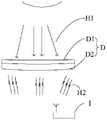
其中,图像传感器可以包括若干成像子区,该成像子区可在入射光线的照射下发生形变,上述反射电磁波信号由图像传感器中的成像子区对电磁波信号反射形成。具体的,如图1b所示,成像子区D可以包括感光层D1和反射层D2。感光层D1可用于接收入射光线H1,并发生与入射光线H1的光线信息对应的形变。反射层D2可发生与感光层D1对应的形变,并反射与入射光线H1对应的反射电磁波信号H2。接收器I接收上述反射电磁波信号H2以进行处理。Wherein, the image sensor may include several imaging sub-regions, the imaging sub-regions can deform under the irradiation of incident light, and the reflected electromagnetic wave signal is formed by the reflection of the electromagnetic wave signal by the imaging sub-region in the image sensor. Specifically, as shown in FIG. 1b, the imaging sub-region D may include a photosensitive layer D1 and a reflective layer D2. The photosensitive layer D1 can be used to receive the incident light H1 and undergo deformation corresponding to the light information of the incident light H1. The reflection layer D2 can deform corresponding to the photosensitive layer D1, and reflect the reflected electromagnetic wave signal H2 corresponding to the incident light H1. The receiver 1 receives the above-mentioned reflected electromagnetic wave signal H2 for processing.
需要说明的是,至少两个成像子区D的形变属性不同,和/或,至少两个成像子区D的电磁波信号反射特性不同,以对不同成像子区D所反射的电磁波信号进行定位和区分。其中,上述“和/或”包括三种情况,一种情况是至少两个成像子区D的形变属性不同,而成像子区D的电磁波反射特性相同的。另一种情况是至少两个成像子区D的电磁波反射特性不同,而成像子区D的变形属性相同。又一种情况是至少两个所述成像子区D的形变属性不同,和/或,至少两个所述成像子区D的电磁波信号反射特性不同。上述三种情况都可以对成像子区D所反射的电磁波信号进行定位和区分。It should be noted that the deformation properties of the at least two imaging sub-regions D are different, and/or the electromagnetic wave signal reflection characteristics of the at least two imaging sub-regions D are different, so as to locate and analyze the electromagnetic wave signals reflected by the different imaging sub-regions D. distinguish. Wherein, the above "and/or" includes three situations. One situation is that the deformation properties of at least two imaging sub-regions D are different, but the electromagnetic wave reflection characteristics of the imaging sub-regions D are the same. Another situation is that the electromagnetic wave reflection properties of at least two imaging sub-regions D are different, and the deformation properties of the imaging sub-regions D are the same. In another case, the deformation properties of the at least two imaging sub-regions D are different, and/or the electromagnetic wave signal reflection properties of the at least two imaging sub-regions D are different. In the above three cases, the electromagnetic wave signal reflected by the imaging sub-region D can be located and distinguished.
在步骤102中,根据反射电磁波信号确定入射光线的光线信息,根据所述光线信息获得待摄场景的第一图像。In
需要说明的是,本公开涉及的入射光线需经过至少一透镜对入射光线进行汇聚以成像,或者通过反射镜对入射光线进行汇聚以成像,本公开并不对此进行限制。It should be noted that the incident light involved in the present disclosure needs to pass through at least one lens to condense the incident light to form an image, or to condense the incident light through a mirror to form an image, which is not limited in the present disclosure.
其中,所述第一图像为所述图像传感器根据所述光线信息形成的拍摄图像,反应出待摄场景未经调整的景深效果。所述光线信息可以包括:入射光线的强度、颜色、极化方向中至少之一。在一实施例中,所述图像传感器包括根据所述反射电磁波信号及与之对应的感光层的形变参数训练出监测模型。为了得到入射光线的光线信息,可以向监测模型发送所述反射电磁波信号,所述监测模型的训练样本包括预先获得的反射电磁波信号与感光层的形变参数之间的数据对。接收到的所述形变参数可以用于确定所述入射光线的光线信息。The first image is a captured image formed by the image sensor according to the light information, and reflects the unadjusted depth-of-field effect of the scene to be captured. The light information may include: at least one of the intensity, color, and polarization direction of the incident light. In one embodiment, the image sensor includes a monitoring model trained according to the reflected electromagnetic wave signal and the deformation parameter of the photosensitive layer corresponding thereto. In order to obtain the light information of the incident light, the reflected electromagnetic wave signal can be sent to the monitoring model, and the training sample of the monitoring model includes a data pair between the reflected electromagnetic wave signal obtained in advance and the deformation parameters of the photosensitive layer. The received deformation parameters can be used to determine the light information of the incident light.
反射层的反射参数和感光层的形变参数是基于同一入射光线而产生的变化,是相互对应且具有同步性的数据。由于不同光致变形材料的感光层对于入射光线发生的形变参数是不同的,但每种光致变形材料都有与之对应的光致变形函数可以计算入射光线的光线信息。The reflection parameters of the reflective layer and the deformation parameters of the photosensitive layer are changes based on the same incident light, and are corresponding and synchronized data. Since the photosensitive layers of different photodeformable materials have different deformation parameters for incident light, each photodeformable material has a corresponding photodeformation function that can calculate the light information of the incident light.
在另一实施例中,可以先对所述反射电磁波信号进行解调,以获得第一信号,再根据所述第一信号恢复出所述入射光线的光线信息。In another embodiment, the reflected electromagnetic wave signal may be demodulated first to obtain a first signal, and then the light information of the incident light can be recovered according to the first signal.
景深通常表征待摄场景相对焦平面清晰成像的物距范围,图像成像子区对应焦内的分布密度大于其对应焦外的图像目标像素密度,以便于目标图像中焦内部分的成像相对焦外部分的成像更为清晰,由此在视觉上呈现焦内清晰、焦外模糊的浅景深图像效果。The depth of field usually represents the object distance range where the scene to be photographed is clearly imaged relative to the focal plane. The distribution density of the corresponding in-focus sub-region in the image imaging sub-region is greater than the pixel density of the corresponding out-of-focus image, so that the imaging of the in-focus part of the target image is relatively out-of-focus. Part of the image is sharper, thereby visually presenting a shallow depth of field image with clear in-focus and blurred out-of-focus images.
在步骤103中,获取针对待摄场景的目标景深信息。In
在一实施例中,目标景深信息可以包括物点深度信息和焦平面信息,获取待摄场景的至少部分焦外物点深度信息与焦平面的相对位置关系,以利用上述相对位置关系对应的调整成像子区的分布密度。In an embodiment, the target depth of field information may include object point depth information and focal plane information, and the relative positional relationship between at least part of the out-of-focus object point depth information and the focal plane of the scene to be shot is obtained, so as to use the adjustment corresponding to the above-mentioned relative positional relationship. The distribution density of the imaging subregion.
在另一实施例中,所述目标景深信息可以包括焦外模糊程度信息,焦外模糊程度包括所述焦平面外的成像子区的弥撒圆分布信息,以利用上述弥撒圆分布信息对应的调整成像子区的分布密度。In another embodiment, the target depth of field information may include out-of-focus blur degree information, and the out-of-focus blur degree includes mass circle distribution information of the imaging sub-region outside the focal plane, so as to use the adjustment corresponding to the mass circle distribution information The distribution density of the imaging subregion.
需要说明的是,在上述实施例中目标景深信息可以通过所述光线信息以经典估计方法获取,也可以通过例如深度传感器、雷达以及网络连接获取,本公开并不对此进行限制。It should be noted that, in the above embodiment, the target depth of field information can be obtained by a classical estimation method through the light information, and can also be obtained through, for example, a depth sensor, a radar and a network connection, which is not limited in the present disclosure.
在步骤104中,根据目标景深信息调整所述成像子区的分布密度,以获得与所述第一图像对应的浅景深效果图像。In
如图1c所示,调整所述成像子区的分布密度的方式可以包括:为至少一个所述成像子区D施加外场E,利用控制部F控制所述外场E向所述成像子区D施加作用力,以使所述成像子区D在平行和/或垂直于入射光线的方向上按照目标景深信息运动。需要说明的是,所述外场可以包括:磁场、电场、光场中至少之一,本公开并不对此进行限制。As shown in FIG. 1c , the manner of adjusting the distribution density of the imaging sub-regions may include: applying an external field E to at least one of the imaging sub-regions D, and using the control part F to control the external field E to apply the external field E to the imaging sub-region D A force is applied to make the imaging sub-region D move according to the target depth of field information in a direction parallel and/or perpendicular to the incident light rays. It should be noted that the external field may include at least one of a magnetic field, an electric field, and an optical field, which is not limited in the present disclosure.
本公开实施例在图像采集过程中所述图像传感器的各成像子区均参与图像采集,成像子区可在入射光线的照射下发生形变,通过反射电磁波信号的变化便于确定入射光线的光线信息。此外,图像传感器的成像子区分布密度已经根据图像成像子区分布密度进行了调整,且图像成像子区分布密度是根据待摄场景的目标景深信息确定。根据调整后的图像传感器获取待摄场景的图像,图像不同区域的清晰度呈现出与成像子区分布密度相应的差异分布。需要清晰呈现的部分会有更多的成像子区参与图像采集,这部分的图像清晰度更高,而所述目标景深信息无需清晰呈现的部分则用相对较少的像素参与图像采集,该部分的图像较为模糊,上述方法提高了图像采集效率。In the embodiment of the present disclosure, each imaging sub-area of the image sensor participates in image acquisition during the image acquisition process, and the imaging sub-area can be deformed under the irradiation of incident light, and the light information of the incident light can be easily determined by the change of the reflected electromagnetic wave signal. In addition, the distribution density of the imaging sub-area of the image sensor has been adjusted according to the distribution density of the image imaging sub-area, and the distribution density of the image imaging sub-area is determined according to the target depth of field information of the scene to be photographed. The image of the scene to be photographed is acquired according to the adjusted image sensor, and the sharpness of different regions of the image presents a different distribution corresponding to the distribution density of the imaging sub-region. The part that needs to be clearly presented will have more imaging sub-regions participating in image acquisition, and the image definition of this part will be higher, while the part of the target depth of field information that does not need to be clearly presented will use relatively fewer pixels to participate in image acquisition. The image is relatively blurry, and the above method improves the image acquisition efficiency.
现针对目标景深信息的获取方式提出如下两个实施例:The following two embodiments are now proposed for the acquisition method of target depth of field information:
图2a是本公开另一示例性实施例的一种浅景深效果成像方法的流程图。如图2a所示,该浅景深效果成像方法可以包括以下步骤:Fig. 2a is a flowchart of a method for imaging a shallow depth of field effect according to another exemplary embodiment of the present disclosure. As shown in Figure 2a, the shallow depth of field effect imaging method may include the following steps:
在步骤201中,获取反射电磁波信号。In
其中,图像传感器可以包括若干成像子区,该成像子区可在入射光线的照射下发生形变,上述反射电磁波信号由图像传感器中的成像子区对电磁波信号反射形成。具体的,成像子区可以包括感光层和反射层。感光层可用于接收入射光线,并发生与入射光线的光线信息对应的形变。反射层可发生与感光层对应的形变,并反射与入射光线对应的反射电磁波信号。接收器接收上述反射电磁波信号以进行处理。Wherein, the image sensor may include several imaging sub-regions, the imaging sub-regions can deform under the irradiation of incident light, and the reflected electromagnetic wave signal is formed by the reflection of the electromagnetic wave signal by the imaging sub-region in the image sensor. Specifically, the imaging sub-region may include a photosensitive layer and a reflective layer. The photosensitive layer can be used for receiving incident light and deforming corresponding to the light information of the incident light. The reflection layer can deform corresponding to the photosensitive layer, and reflect the reflected electromagnetic wave signal corresponding to the incident light. The receiver receives the above-mentioned reflected electromagnetic wave signal for processing.
所述图像传感器包括根据所述反射电磁波信号及与之对应的感光层的形变参数训练出监测模型。具体的,当入射光线照射到成像子区上时,采集每个成像子区返回的反射电磁波信号以及与之对应的感光层形变参数,形成训练样本。通过上述原理,针对不同入射光线的极化方向、强度、颜色等可以记录到大量的训练样本。基于上述训练样本,自动生成大量的关于逻辑回归的问题,进而学习出训练样本与训练模型性能之间的存在的某种关系,从而得到一个简单的规则以用于将反射电磁波信号和感光层的形变参数对应起来。The image sensor includes a monitoring model trained according to the reflected electromagnetic wave signal and the deformation parameter of the photosensitive layer corresponding thereto. Specifically, when the incident light irradiates the imaging sub-region, the reflected electromagnetic wave signal returned by each imaging sub-region and the corresponding photosensitive layer deformation parameters are collected to form a training sample. Through the above principles, a large number of training samples can be recorded for different incident light polarization directions, intensities, colors, etc. Based on the above training samples, a large number of logistic regression questions are automatically generated, and then a certain relationship between the training samples and the performance of the training model is learned, so as to obtain a simple rule for combining the reflected electromagnetic wave signal and the photosensitive layer. The deformation parameters correspond.
在步骤202中,向监测模型发送反射电磁波信号,监测模型的训练样本包括预先获得的反射电磁波信号与感光层的形变参数之间的数据对。In
在步骤203中,根据接收到的形变参数确定入射光线的光线信息,根据所述光线信息获得待摄场景的第一图像。In
其中,所述第一图像为所述图像传感器根据所述光线信息形成的拍摄图像,反应出待摄场景未经调整的景深效果。在上述实施例中,为了得到入射光线的光线信息,可以向所述监测模型发送所述反射电磁波信号,监测模型根据所述反射电磁波信号输出与之对应的感光层的形变参数。根据接收到的所述形变参数确定所述入射光线的光线信息。其中,所述光线信息可以包括:入射光线的强度、颜色、极化方向中至少之一。上述反射层和感光层的形变参数是基于同一入射光线而产生的变化,是相互对应且具有同步性的数据。由于不同光致变形材料的感光层对于入射光线发生的形变参数是不同的,但每种光致变形材料都有与之对应的光致变形函数可以计算入射光线的光线信息。The first image is a captured image formed by the image sensor according to the light information, and reflects the unadjusted depth of field effect of the scene to be captured. In the above embodiment, in order to obtain the light information of the incident light, the reflected electromagnetic wave signal may be sent to the monitoring model, and the monitoring model outputs the corresponding deformation parameter of the photosensitive layer according to the reflected electromagnetic wave signal. The light information of the incident light is determined according to the received deformation parameter. Wherein, the light information may include: at least one of the intensity, color, and polarization direction of the incident light. The above-mentioned deformation parameters of the reflective layer and the photosensitive layer are changes based on the same incident light, and are corresponding and synchronized data. Since the photosensitive layers of different photodeformable materials have different deformation parameters for incident light, each photodeformable material has a corresponding photodeformation function that can calculate the light information of the incident light.
需要说明的是,步骤202以及步骤203可以被替换成:对所述反射电磁波信号进行解调,以获得第一信号;根据所述第一信号恢复出所述入射光线的光线信息。It should be noted that, steps 202 and 203 may be replaced by: demodulating the reflected electromagnetic wave signal to obtain a first signal; and recovering light information of the incident light according to the first signal.
成像子区产生的形变可以包括形状变化、面积变化、密度变化、光滑程度变化中至少之一,上述形变的发生导致反射层反射特性的变化,反射特性可以通过信道参数或者散射参数来描述,本公开并不对此进行限定。由于反射特性的变化,改变了反射电磁波信号G的频谱和幅度特性,利用经典的信号解调方法对所述反射电磁波信号G进行解调,以获得第一信号,并根据解调后的第一信号恢复出入射光线的光线信息。其中,反射电磁波信号G在成像子区收到入射光线照射时可以包括如图2b、图2c、图2d、图2e所示的几种常见变形模式。反射层经入射光线照射发生变形后,其反射出的反射电磁波信号G中携带了入射光线的光线信息,解调反射电磁波信号G即可获得包含入射光线信息的第一信号,因此第一信号可用于恢复入射光线的光线信息。The deformation generated by the imaging sub-region may include at least one of shape change, area change, density change, and smoothness change. The occurrence of the above deformation leads to changes in the reflection characteristics of the reflective layer. The reflection characteristics can be described by channel parameters or scattering parameters. The disclosure does not limit this. Due to the change of the reflection characteristics, the spectrum and amplitude characteristics of the reflected electromagnetic wave signal G are changed, and the reflected electromagnetic wave signal G is demodulated by the classical signal demodulation method to obtain the first signal, and according to the demodulated first signal G The signal recovers the light information of the incident light. The reflected electromagnetic wave signal G may include several common deformation modes as shown in FIG. 2b, FIG. 2c, FIG. 2d, and FIG. 2e when the imaging sub-region receives incident light. After the reflective layer is deformed by the incident light, the reflected electromagnetic wave signal G that it reflects carries the light information of the incident light, and the first signal containing the incident light information can be obtained by demodulating the reflected electromagnetic wave signal G, so the first signal can be used to recover the ray information of the incident ray.
在步骤204中,获取针对待摄场景的物点深度信息。In
其中,物点深度信息可以通过所述光线信息用经典深度估计方法获取,例如通过双目立体视觉、光照阴影信息、变焦调焦、散焦弥撒圆信息等方法,也可以通过例如深度传感器、雷达以及网络连接等外部方法获取,本公开并不对此进行限制。The object point depth information can be obtained through the light information by classical depth estimation methods, such as binocular stereo vision, light and shadow information, zoom focusing, defocused mass circle information, etc., or can also be obtained through, for example, depth sensors, radar and external methods such as network connection, which are not limited in the present disclosure.
在步骤205中,获取针对待摄场景的焦平面信息。In
在一实施例中,所述焦平面可根据感兴趣区(Region of Interest,简称ROI)信息确定。所述感兴趣区可包括但不限于以下一种或多种:用户选择的待摄场景在所述图像传感器的预览图像的至少一个区域、用户注视的所述预览图像的至少一个区域、成像设备对预览图像自动检测得到的感兴趣区。该方案根据所述感兴趣区确定待摄场景的焦平面,使得所述焦平面的确定与实际用户需求更为吻合,可更好满足用户个性化的应用需求。In one embodiment, the focal plane may be determined according to region of interest (Region of Interest, ROI for short) information. The region of interest may include, but is not limited to, one or more of the following: at least one area of the preview image of the image sensor for the scene to be photographed selected by the user, at least one area of the preview image that the user gazes at, and an imaging device The region of interest obtained automatically from the preview image. In this solution, the focal plane of the scene to be photographed is determined according to the region of interest, so that the determination of the focal plane is more consistent with the actual user requirements, and can better meet the user's personalized application requirements.
在另一实施例中,待摄场景的焦平面可根据图像分析的结果确定,例如:对所述预览图像进行人脸识别,根据识别结果将人脸的对焦平面确定为所述待摄场景的焦平面。又例如:对所述预览图像进行移动物体识别,根据识别结果将移动物体的相应区的对焦平面确定为该待摄场景的焦平面。该方案可根据预览图像的图像分析结果确定待摄场景的焦平面,使得待摄场景的焦平面的确定更为智能,提高所述焦平面确定的效率和普适性。In another embodiment, the focal plane of the scene to be photographed can be determined according to the result of image analysis, for example, face recognition is performed on the preview image, and the focal plane of the face is determined as the focal plane of the scene to be photographed according to the recognition result. focal plane. In another example, a moving object is recognized on the preview image, and the focal plane of the corresponding area of the moving object is determined as the focal plane of the scene to be photographed according to the recognition result. The solution can determine the focal plane of the scene to be photographed according to the image analysis result of the preview image, so that the determination of the focal plane of the scene to be photographed is more intelligent, and the efficiency and universality of the determination of the focal plane are improved.
在步骤206中,根据物点深度信息和焦平面信息确定所述目标景深信息。In
在本实施例中,目标景深信息可以是待摄场景物点深度位置相对于焦平面位置的距离。其中,物点深度位置和焦平面位置可已通过步骤205和步骤206获得。In this embodiment, the target depth of field information may be the distance of the depth position of the object point in the scene to be shot relative to the position of the focal plane. Wherein, the depth position of the object point and the position of the focal plane may have been obtained through
在步骤207中,根据目标景深信息调整成像子区的分布密度,以获得与所述第一图像对应的浅景深效果图像。In
在本实施例中,根据目标景深信息确定成像子区的分布密度,具体的,成像子区目标分布密度对应于待摄场景中焦外物点位置距离焦平面位置的远近。用于表达距离焦平面较近的物点的成像子区的分布密度大于用于表达距离焦平面较远的物点的成像子区的分布密度,以便于图像中不同距离区间的成像的清晰度存在差异。距离焦平面较近的物点成像较为清晰而距离焦平面较远的物点成像较为模糊,由此在视觉上呈现越近距离物点成像越清晰、越远距离物点成像越模糊的浅景深图像效果。In this embodiment, the distribution density of the imaging sub-region is determined according to the target depth of field information. Specifically, the target distribution density of the imaging sub-region corresponds to the distance between the position of the out-of-focus object point and the position of the focal plane in the scene to be photographed. The distribution density of the imaging sub-region used to express the object point closer to the focal plane is greater than the distribution density of the imaging sub-region used to express the object point far from the focal plane, so as to facilitate the imaging clarity of different distance intervals in the image has a difference. The image of the object point closer to the focal plane is clearer, while the image of the object point farther away from the focal plane is more blurred, which visually presents a shallow depth of field that the closer the object point is, the clearer the image is, and the farther the object point is, the blurrier the image is. image effects.
在上述实施例中,调整所述成像子区的分布密度的方式可以包括:为至少一个所述成像子区施加外场,利用所述外场向所述成像子区施加作用力,以使所述成像子区在平行和/或垂直于入射光线的方向上根据所述目标景深信息运动。需要说明的是,所述外场可以包括:磁场、电场、光场中至少之一,本公开并不对此进行限制。In the above embodiment, the manner of adjusting the distribution density of the imaging sub-regions may include: applying an external field to at least one of the imaging sub-regions, and using the external field to apply a force to the imaging sub-regions, so as to make the imaging sub-regions The sub-regions move in a direction parallel and/or perpendicular to the incident light rays according to the target depth of field information. It should be noted that the external field may include at least one of a magnetic field, an electric field, and an optical field, which is not limited in the present disclosure.
图3a是本公开另一示例性实施例的一种变焦方法的流程图。如图3a所示,该变焦方法可以包括以下步骤:Fig. 3a is a flowchart of a zooming method according to another exemplary embodiment of the present disclosure. As shown in Figure 3a, the zooming method may include the following steps:
在步骤301中,获取反射电磁波信号。In
其中,图像传感器可以包括若干成像子区,该成像子区可在入射光线的照射下发生形变,上述反射电磁波信号由图像传感器中的成像子区对电磁波信号反射形成。具体的,成像子区可以包括感光层和反射层。感光层可用于接收入射光线,并发生与入射光线的光线信息对应的形变。反射层可发生与感光层对应的形变,并反射与入射光线对应的反射电磁波信号。接收器接收上述反射电磁波信号以进行处理。Wherein, the image sensor may include several imaging sub-regions, the imaging sub-regions can deform under the irradiation of incident light, and the reflected electromagnetic wave signal is formed by the reflection of the electromagnetic wave signal by the imaging sub-region in the image sensor. Specifically, the imaging sub-region may include a photosensitive layer and a reflective layer. The photosensitive layer can be used for receiving incident light and deforming corresponding to the light information of the incident light. The reflection layer can deform corresponding to the photosensitive layer, and reflect the reflected electromagnetic wave signal corresponding to the incident light. The receiver receives the above-mentioned reflected electromagnetic wave signal for processing.
在步骤302中,向监测模型发送反射电磁波信号,监测模型的训练样本包括预先获得的反射电磁波信号与感光层的形变参数之间的数据对。In
在步骤303中,根据接收到的形变参数确定入射光线的光线信息,根据所述光线信息获得待摄场景的第一图像。In
其中,所述第一图像为所述图像传感器根据所述光线信息形成的拍摄图像,反应出待摄场景未经调整的景深效果。在上述实施例中,图像传感器包括根据反射电磁波信号及与之对应的感光层的形变参数训练出监测模型。为了得到入射光线的光线信息,可以向所述监测模型发送所述反射电磁波信号,监测模型根据所述反射电磁波信号输出与之对应的感光层的形变参数。根据接收到的所述形变参数确定所述入射光线的光线信息。其中,所述光线信息可以包括:入射光线的强度、颜色、极化方向中至少之一。上述反射层和感光层的形变参数是基于同一入射光线而产生的变化,是相互对应且具有同步性的数据。由于不同光致变形材料的感光层对于入射光线发生的形变参数是不同的,但每种光致变形材料都有与之对应的光致变形函数可以计算入射光线的光线信息。The first image is a captured image formed by the image sensor according to the light information, and reflects the unadjusted depth-of-field effect of the scene to be captured. In the above embodiment, the image sensor includes a monitoring model trained according to the reflected electromagnetic wave signal and the deformation parameters of the photosensitive layer corresponding thereto. In order to obtain the light information of the incident light, the reflected electromagnetic wave signal may be sent to the monitoring model, and the monitoring model outputs the corresponding deformation parameters of the photosensitive layer according to the reflected electromagnetic wave signal. The light information of the incident light is determined according to the received deformation parameter. Wherein, the light information may include: at least one of the intensity, color, and polarization direction of the incident light. The above-mentioned deformation parameters of the reflective layer and the photosensitive layer are changes based on the same incident light, and are corresponding and synchronized data. Since the photosensitive layers of different photodeformable materials have different deformation parameters for incident light, each photodeformable material has a corresponding photodeformation function that can calculate the light information of the incident light.
需要说明的是,步骤302以及步骤303可以被替换成:对所述反射电磁波信号进行解调,以获得第一信号;根据所述第一信号恢复出所述入射光线的光线信息。It should be noted that, steps 302 and 303 may be replaced by: demodulating the reflected electromagnetic wave signal to obtain a first signal; and recovering light information of the incident light according to the first signal.
在步骤304中,获取针对待摄场景的物点深度信息。In
其中,物点深度信息可以通过所述光线信息用经典深度估计方法获取,例如通过双目立体视觉、光照阴影信息、变焦调焦、散焦弥撒圆信息等方法,也可以通过例如深度传感器、雷达以及网络连接等外部方法获取,本公开并不对此进行限制。The object point depth information can be obtained through the light information by classical depth estimation methods, such as binocular stereo vision, light and shadow information, zoom focusing, defocused mass circle information, etc., or can also be obtained through, for example, depth sensors, radar and external methods such as network connection, which are not limited in the present disclosure.
在步骤305中,获取针对待摄场景的焦外模糊程度信息。In
所述焦外模糊程度信息的获取方式不受限制,例如可由用户确定,或者,可由待摄场景的深度信息确定,或者,可由成像设备预先确定,等等。The manner of acquiring the out-of-focus blur degree information is not limited, for example, it can be determined by a user, or it can be determined by the depth information of the scene to be shot, or it can be predetermined by an imaging device, and so on.
在一实施例中,焦外模糊程度信息包括:待摄场景的至少部分焦外物点在图像传感器的至少部分成像点的弥散圆分布信息。在该情形下,可根据至少部分成像点的弥散圆分布信息确定成像子区分布密度。确定弥散圆分布信息的具体实现方式不受限制可包括:确定待摄场景的至少一焦外物点在图像传感器的至少一成像点的弥散圆(circle ofconfusion)信息,根据待摄场景的至少部分其他焦外物点与焦平面的距离以及确定的至少一成像点的弥散圆信息确定至少部分其他成像点的弥散圆信息。例如图3b,P为焦平面上的物点,Q为焦平面外物点,可通过计算确定待摄场景中焦外物点Q在所述图像传感器的成像点的弥散圆直径。具体的,根据确定的上述物点相应成像点的弥散圆直径、上述物点的物距、已知的待摄场景的镜头的焦距以及对焦平面的物距,依据弥散圆直径计算公式可确定出用户期望的虚拟光圈值N。之后结合待摄场景中其他一个或多个物点的物距,可根据以下弥散圆直径计算公式确定待摄场景中其他一个或多个物点在图像传感器的相应成像点的弥散圆直径:In one embodiment, the out-of-focus blur degree information includes: circle of confusion distribution information of at least part of out-of-focus object points of the scene to be photographed at at least part of the imaging points of the image sensor. In this case, the distribution density of the imaging sub-region can be determined according to the distribution information of the circle of confusion of at least part of the imaging points. The specific implementation manner of determining the distribution information of the circle of confusion is not limited, and may include: determining the circle of confusion (circle of confusion) information of at least one out-of-focus object point of the scene to be shot at at least one imaging point of the image sensor, according to at least part of the scene to be shot The distance between the other out-of-focus object points and the focal plane and the determined circle of confusion information of at least one imaging point determine the circle of confusion information of at least part of the other imaging points. For example, in Fig. 3b, P is the object point on the focal plane, Q is the object point outside the focal plane, and the diameter of the circle of confusion at the imaging point of the image sensor for the out-of-focus object point Q in the scene to be shot can be determined by calculation. Specifically, according to the determined diameter of the circle of confusion of the imaging point corresponding to the above-mentioned object point, the object distance of the above-mentioned object point, the focal length of the lens of the known scene to be photographed, and the object distance of the focal plane, according to the calculation formula of the diameter of the circle of confusion, it can be determined that The virtual aperture value N desired by the user. Then, combined with the object distance of one or more other object points in the scene to be photographed, the circle of confusion diameter of the other one or more object points in the scene to be photographed at the corresponding imaging point of the image sensor can be determined according to the following formula for calculating the diameter of the circle of confusion:

上式中,f表示镜头的焦距,U1表示对焦平面的物距,U2表示待计算弥散圆的物点的物距,N表示用户期望的虚拟光圈值,d表示U2对应物点在图像传感器的相应成像点的弥散圆直径。In the above formula, f represents the focal length of the lens, U1 represents the object distance of the focal plane, U2 represents the object distance of the object point of the circle of confusion to be calculated, N represents the virtual aperture value expected by the user, and d represents the corresponding object point of U2 in the image sensor. The diameter of the circle of confusion for the corresponding imaging point.
在步骤306中,根据焦外模糊程度信息调整成像子区的分布密度,以获得与所述第一图像对应的浅景深效果图像。In
得到各物点相应成像点的弥散圆直径之后,即可根据弥散圆分布信息确定成像子区分布密度。当确定的不同弥散圆的范围存在一定重叠时,可根据实际需要确定弥散圆重叠区域的成像子区分布密度。如图3c所示,三个焦外物点在图像传感器的三个成像点的弥散圆分别表示为A、B和C,三个弥散圆的半径依次增大。其中,弥散圆直径小的区域的成像子区分布密度大于弥散圆直径大的区域的成像子区分布密度。然而三个弥散圆有一定的重复,该情形下可遵循一定的规则确定不同区域的成像子区分布密度,规则可包括但不限于大密度优先规则,例如A与B或C的交集对应成像子区分布密度为A对应的成像子区分布密度a,B与C的交集对应图像目标像素密度为B对应的成像子区分布密度b,由此在视觉上呈现出浅景深图像效果。该方案使得焦外模糊程度的设定更为灵活。After the diameter of the circle of confusion of the corresponding imaging point of each object point is obtained, the distribution density of the imaging sub-region can be determined according to the distribution information of the circle of confusion. When the determined ranges of the different circles of confusion overlap to a certain extent, the distribution density of the imaging sub-regions in the overlapping area of the circles of confusion can be determined according to actual needs. As shown in Fig. 3c, the circles of confusion of the three out-of-focus object points at the three imaging points of the image sensor are denoted as A, B, and C, respectively, and the radii of the three circles of confusion increase in turn. Wherein, the distribution density of the imaging sub-regions in the region with a small diameter of the circle of confusion is greater than the distribution density of the imaging sub-region in the region with a large diameter of the circle of confusion. However, the three circles of confusion have certain repetitions. In this case, certain rules can be followed to determine the distribution densities of imaging sub-regions in different regions. The rules may include but are not limited to high-density priority rules. For example, the intersection of A and B or C corresponds to the imaging sub-region. The area distribution density is the imaging sub-area distribution density a corresponding to A, and the intersection of B and C corresponds to the imaging sub-area distribution density b corresponding to the image target pixel density B, thereby visually presenting a shallow depth of field image effect. This scheme makes the setting of the degree of out-of-focus blur more flexible.
在上述实施例中,调整所述成像子区的分布密度的方式可以包括:为至少一个所述成像子区施加外场,利用所述外场向所述成像子区施加作用力,以使所述成像子区在平行和/或垂直于入射光线的方向上根据所述目标景深信息运动。需要说明的是,所述外场可以包括:磁场、电场、光场中至少之一,本公开并不对此进行限制。In the above embodiment, the manner of adjusting the distribution density of the imaging sub-regions may include: applying an external field to at least one of the imaging sub-regions, and using the external field to apply a force to the imaging sub-regions, so as to make the imaging sub-regions The sub-regions move in a direction parallel and/or perpendicular to the incident light rays according to the target depth of field information. It should be noted that the external field may include at least one of a magnetic field, an electric field, and an optical field, which is not limited in the present disclosure.
根据上述实施例,本公开进一步提出一种浅景深效果成像装置,应用于图像传感器。图4是本公开一示例性实施例的一种浅景深效果成像装置的结构示意图,如图4所示,上述浅景深效果成像装置包括获取单元41、处理单元42、确定单元43和执行单元44。According to the above embodiments, the present disclosure further proposes a shallow depth-of-field effect imaging device, which is applied to an image sensor. FIG. 4 is a schematic structural diagram of a shallow depth of field effect imaging apparatus according to an exemplary embodiment of the present disclosure. As shown in FIG. 4 , the above shallow depth of field effect imaging apparatus includes an
获取单元41被配置为获取反射电磁波信号。其中,所述反射电磁波信号由图像传感器中的成像子区对电磁波信号反射形成,所述图像传感器包括若干成像子区,所述成像子区可在入射光线的照射下发生形变。The
处理单元42被配置为根据所述反射电磁波信号确定所述入射光线的光线信息,根据所述光线信息获得待摄场景的第一图像。The
确定单元43被配置为获取针对待摄场景的目标景深信息。The
执行单元44被配置为根据所述目标景深信息调整所述成像子区的分布密度,以获得与所述第一图像对应的浅景深效果图像。The
本公开还提出一种浅景深效果成像装置,图5是本公开一示例性实施例的一种处理单元的结构示意图,如图5所示,在前述图4所示实施例的基础上,所述处理单元42可以包括发送子单元421、接收子单元422、第三处理子单元423。其中:The present disclosure also proposes an imaging device with a shallow depth of field effect. FIG. 5 is a schematic structural diagram of a processing unit according to an exemplary embodiment of the present disclosure. As shown in FIG. 5 , on the basis of the foregoing embodiment shown in FIG. The
发送子单元421被配置为向监测模型发送所述反射电磁波信号,所述监测模型的训练样本包括预先获得的反射电磁波信号与感光层的形变参数之间的数据对。The sending
接收子单元422被配置为接收所述监测模型输出的感光层的形变参数。The receiving
第三处理子单元423被配置为根据所述形变参数确定所述入射光线的光线信息,根据所述光线信息获得待摄场景的第一图像。The
图6是本公开另一示例性实施例的一种处理单元的结构示意图,如图6所示,在前述图4所示实施例的基础上,所述处理单元42可以包括第一处理子单元424和第三处理子单元425。其中:FIG. 6 is a schematic structural diagram of a processing unit according to another exemplary embodiment of the present disclosure. As shown in FIG. 6 , on the basis of the foregoing embodiment shown in FIG. 4 , the
第一处理子单元424被配置为对所述反射电磁波信号进行解调,以获得第一信号。The
第二处理子单元425被配置为根据所述第一信号恢复出所述入射光线的光线信息,根据所述光线信息获得待摄场景的第一图像。The
图7是本公开一示例性实施例的一种确定单元的结构示意图。如图7所示,在前述图4所示实施例的基础上,确定单元43可以包括第一确定子单元431、第二确定子单元432、第三确定子单元433。其中:FIG. 7 is a schematic structural diagram of a determination unit according to an exemplary embodiment of the present disclosure. As shown in FIG. 7 , based on the foregoing embodiment shown in FIG. 4 , the
第一确定子单元431被配置为获取针对待摄场景的物点深度信息。The
第二确定子单元432被配置为获取针对待摄场景的焦平面信息。The
第三确定子单元433被配置为根据所述物点深度信息和所述焦平面信息确定所述目标景深信息。The
图8是本公开另一示例性实施例的一种确定单元的结构示意图。如图8所示,在前述图4所示实施例的基础上,确定单元43可以包括第一确定子单元431、和第四确定子单元434。其中:FIG. 8 is a schematic structural diagram of a determination unit according to another exemplary embodiment of the present disclosure. As shown in FIG. 8 , based on the foregoing embodiment shown in FIG. 4 , the
第一确定子单元431被配置为获取针对待摄场景的物点深度信息。The
第四确定子单元434被配置为根据所述光线信息确定焦外模糊程度信息。The
图9是本公开一示例性实施例的一种执行单元的结构示意图。如图9所示,在前述图4所示实施例的基础上,执行单元44可以包括第一执行子单元441、第二执行子单元442、第三执行子单元443和第四执行子单元444。其中:FIG. 9 is a schematic structural diagram of an execution unit according to an exemplary embodiment of the present disclosure. As shown in FIG. 9 , based on the foregoing embodiment shown in FIG. 4 , the
第一执行子单元441被配置为根据所述目标景深信息调整所述成像子区在垂直于入射光线方向上的分布密度。The
第二执行子单元442被配置为根据所述目标景深信息调整所述成像子区在平行于入射光线方向上的分布密度。The
第三执行子单元443被配置为为至少一个所述成像子区施加外场。The
第四执行子单元444被配置为利用所述外场向所述成像子区施加作用力,以获得与所述第一图像对应的浅景深效果图像。The
关于上述实施例中的装置,其中各个模块执行操作的具体方式已经在有关该方法的实施例中进行了详细描述,此处将不做详细阐述说明。Regarding the apparatus in the above-mentioned embodiment, the specific manner in which each module performs operations has been described in detail in the embodiment of the method, and will not be described in detail here.
对于装置实施例而言,由于其基本对应于方法实施例,所以相关之处参见方法实施例的部分说明即可。以上所描述的装置实施例仅仅是示意性的,其中所述作为分离部件说明的单元可以是或者也可以不是物理上分开的,作为单元显示的部件可以是或者也可以不是物理单元,即可以位于一个地方,或者也可以分布到多个网络单元上。可以根据实际的需要选择其中的部分或者全部模块来实现本公开方案的目的。本领域普通技术人员在不付出创造性劳动的情况下,即可以理解并实施。For the apparatus embodiments, since they basically correspond to the method embodiments, reference may be made to the partial descriptions of the method embodiments for related parts. The device embodiments described above are only illustrative, wherein the units described as separate components may or may not be physically separated, and the components shown as units may or may not be physical units, that is, they may be located in One place, or it can be distributed over multiple network elements. Some or all of the modules can be selected according to actual needs to achieve the purpose of the solution of the present disclosure. Those of ordinary skill in the art can understand and implement it without creative effort.
本公开进一步提出一种电子设备,该电子设备可以包括处理器,所述处理器被配置为实现上述浅景深效果成像方法。The present disclosure further proposes an electronic device, which may include a processor configured to implement the above-mentioned shallow depth-of-field effect imaging method.
在一示例性实施例中,本公开还提供了一种包括指令的非临时性计算机可读存储介质。例如包括指令的存储器,上述指令可由求救装置的处理器执行后,实现本公开的上述浅景深效果成像方法。例如,所述非临时性计算机可读存储介质可以是ROM,随机存取存储器(RAM)、CD-ROM、磁带、软盘和光数据存储设备等。In an exemplary embodiment, the present disclosure also provides a non-transitory computer-readable storage medium including instructions. For example, the memory includes instructions, and the instructions can be executed by the processor of the rescue device to implement the imaging method for the shallow depth of field effect of the present disclosure. For example, the non-transitory computer-readable storage medium may be ROM, random access memory (RAM), CD-ROM, magnetic tape, floppy disk, optical data storage device, and the like.
本领域技术人员在考虑说明书及实践这里公开的技术方案后,将容易想到本公开的其它实施方案。本申请旨在涵盖本公开的任何变型、用途或者适应性变化,这些变型、用途或者适应性变化遵循本公开的一般性原理并包括本公开未公开的本技术领域中的公知常识或惯用技术手段。说明书和实施例仅被视为示例性的,本公开的真正范围和精神由下面的权利要求指出。Other embodiments of the present disclosure will readily occur to those skilled in the art upon consideration of the specification and practice of the technical solutions disclosed herein. This application is intended to cover any variations, uses, or adaptations of the present disclosure that follow the general principles of the present disclosure and include common knowledge or techniques in the technical field not disclosed by the present disclosure . The specification and examples are to be regarded as exemplary only, with the true scope and spirit of the disclosure being indicated by the following claims.
应当理解的是,本公开并不局限于上面已经描述并在附图中示出的精确结构,并且可以在不脱离其范围进行各种修改和改变。本公开的范围仅由所附的权利要求来限制。It is to be understood that the present disclosure is not limited to the precise structures described above and illustrated in the accompanying drawings, and that various modifications and changes may be made without departing from the scope thereof. The scope of the present disclosure is limited only by the appended claims.
Claims (22)
Translated fromChinesePriority Applications (1)
| Application Number | Priority Date | Filing Date | Title |
|---|---|---|---|
| CN201710819207.5ACN107592455B (en) | 2017-09-12 | 2017-09-12 | Shallow depth of field effect imaging method and device and electronic equipment |
Applications Claiming Priority (1)
| Application Number | Priority Date | Filing Date | Title |
|---|---|---|---|
| CN201710819207.5ACN107592455B (en) | 2017-09-12 | 2017-09-12 | Shallow depth of field effect imaging method and device and electronic equipment |
Publications (2)
| Publication Number | Publication Date |
|---|---|
| CN107592455A CN107592455A (en) | 2018-01-16 |
| CN107592455Btrue CN107592455B (en) | 2020-03-17 |
Family
ID=61050526
Family Applications (1)
| Application Number | Title | Priority Date | Filing Date |
|---|---|---|---|
| CN201710819207.5AActiveCN107592455B (en) | 2017-09-12 | 2017-09-12 | Shallow depth of field effect imaging method and device and electronic equipment |
Country Status (1)
| Country | Link |
|---|---|
| CN (1) | CN107592455B (en) |
Families Citing this family (2)
| Publication number | Priority date | Publication date | Assignee | Title |
|---|---|---|---|---|
| CN108337434B (en)* | 2018-03-27 | 2020-05-22 | 中国人民解放军国防科技大学 | Out-of-focus virtual refocusing method for light field array camera |
| CN111835968B (en)* | 2020-05-28 | 2022-02-08 | 北京迈格威科技有限公司 | Image definition restoration method and device and image shooting method and device |
Citations (4)
| Publication number | Priority date | Publication date | Assignee | Title |
|---|---|---|---|---|
| CN104159038A (en)* | 2014-08-26 | 2014-11-19 | 北京智谷技术服务有限公司 | Method and device of imaging control of image with shallow depth of field effect as well as imaging equipment |
| CN104469147A (en)* | 2014-11-20 | 2015-03-25 | 北京智谷技术服务有限公司 | Light field acquisition control method and device, light field acquisition device |
| CN106161912A (en)* | 2015-03-24 | 2016-11-23 | 北京智谷睿拓技术服务有限公司 | Focusing method and device, capture apparatus |
| CN106161910A (en)* | 2015-03-24 | 2016-11-23 | 北京智谷睿拓技术服务有限公司 | Image formation control method and device, imaging device |
Family Cites Families (2)
| Publication number | Priority date | Publication date | Assignee | Title |
|---|---|---|---|---|
| CN105472233B (en)* | 2014-09-09 | 2019-01-18 | 北京智谷技术服务有限公司 | Optical field acquisition control method and device, optical field acquisition equipment |
| CN104243823B (en)* | 2014-09-15 | 2018-02-13 | 北京智谷技术服务有限公司 | Optical field acquisition control method and device, optical field acquisition equipment |
- 2017
- 2017-09-12CNCN201710819207.5Apatent/CN107592455B/enactiveActive
Patent Citations (4)
| Publication number | Priority date | Publication date | Assignee | Title |
|---|---|---|---|---|
| CN104159038A (en)* | 2014-08-26 | 2014-11-19 | 北京智谷技术服务有限公司 | Method and device of imaging control of image with shallow depth of field effect as well as imaging equipment |
| CN104469147A (en)* | 2014-11-20 | 2015-03-25 | 北京智谷技术服务有限公司 | Light field acquisition control method and device, light field acquisition device |
| CN106161912A (en)* | 2015-03-24 | 2016-11-23 | 北京智谷睿拓技术服务有限公司 | Focusing method and device, capture apparatus |
| CN106161910A (en)* | 2015-03-24 | 2016-11-23 | 北京智谷睿拓技术服务有限公司 | Image formation control method and device, imaging device |
Also Published As
| Publication number | Publication date |
|---|---|
| CN107592455A (en) | 2018-01-16 |
Similar Documents
| Publication | Publication Date | Title |
|---|---|---|
| CN107087107B (en) | Image processing apparatus and method based on dual camera | |
| CN113129241B (en) | Image processing method and device, computer readable medium and electronic equipment | |
| US10269130B2 (en) | Methods and apparatus for control of light field capture object distance adjustment range via adjusting bending degree of sensor imaging zone | |
| JP6593629B2 (en) | Image processing apparatus, solid-state imaging device, and electronic device | |
| CN108076278B (en) | A kind of automatic focusing method, device and electronic equipment | |
| WO2019105154A1 (en) | Image processing method, apparatus and device | |
| JP4497211B2 (en) | Imaging apparatus, imaging method, and program | |
| US9313419B2 (en) | Image processing apparatus and image pickup apparatus where image processing is applied using an acquired depth map | |
| WO2019105214A1 (en) | Image blurring method and apparatus, mobile terminal and storage medium | |
| JP5134694B2 (en) | Image processing apparatus and image processing method | |
| WO2018228467A1 (en) | Image exposure method and device, photographing device, and storage medium | |
| WO2016101742A1 (en) | Light field collection control methods and apparatuses, light field collection devices | |
| US20120320230A1 (en) | Imaging device and distance information detecting method | |
| CN108154514A (en) | Image processing method, device and equipment | |
| WO2021134179A1 (en) | Focusing method and apparatus, photographing device, movable platform and storage medium | |
| US11347133B2 (en) | Image capturing apparatus, image processing apparatus, control method, and storage medium | |
| JP2012514886A (en) | Video data acquisition method and apparatus | |
| CN111526282A (en) | Method and device for shooting with adjustable depth of field based on flight time | |
| CN107592455B (en) | Shallow depth of field effect imaging method and device and electronic equipment | |
| JP2009284056A (en) | Image processing apparatus, method, and program | |
| US12333752B2 (en) | Image processing apparatus and method, and image capturing apparatus and control method thereof, and storage medium | |
| US9094581B2 (en) | Imaging device and distance information detecting method | |
| KR101737260B1 (en) | Camera system for extracting depth from images of different depth of field and opertation method thereof | |
| CN118301471A (en) | Image processing method, apparatus, electronic device, and computer-readable storage medium | |
| JP2019083580A (en) | Image processing apparatus, image processing method, and program |
Legal Events
| Date | Code | Title | Description |
|---|---|---|---|
| PB01 | Publication | ||
| PB01 | Publication | ||
| SE01 | Entry into force of request for substantive examination | ||
| SE01 | Entry into force of request for substantive examination | ||
| GR01 | Patent grant | ||
| GR01 | Patent grant |