CN107550524B - Conveying device - Google Patents
Conveying deviceDownload PDFInfo
- Publication number
- CN107550524B CN107550524BCN201610518125.2ACN201610518125ACN107550524BCN 107550524 BCN107550524 BCN 107550524BCN 201610518125 ACN201610518125 ACN 201610518125ACN 107550524 BCN107550524 BCN 107550524B
- Authority
- CN
- China
- Prior art keywords
- axial
- limiting
- rod
- limiting member
- stopper
- Prior art date
- Legal status (The legal status is an assumption and is not a legal conclusion. Google has not performed a legal analysis and makes no representation as to the accuracy of the status listed.)
- Active
Links
Images


Classifications
- A—HUMAN NECESSITIES
- A61—MEDICAL OR VETERINARY SCIENCE; HYGIENE
- A61F—FILTERS IMPLANTABLE INTO BLOOD VESSELS; PROSTHESES; DEVICES PROVIDING PATENCY TO, OR PREVENTING COLLAPSING OF, TUBULAR STRUCTURES OF THE BODY, e.g. STENTS; ORTHOPAEDIC, NURSING OR CONTRACEPTIVE DEVICES; FOMENTATION; TREATMENT OR PROTECTION OF EYES OR EARS; BANDAGES, DRESSINGS OR ABSORBENT PADS; FIRST-AID KITS
- A61F2/00—Filters implantable into blood vessels; Prostheses, i.e. artificial substitutes or replacements for parts of the body; Appliances for connecting them with the body; Devices providing patency to, or preventing collapsing of, tubular structures of the body, e.g. stents
- A61F2/95—Instruments specially adapted for placement or removal of stents or stent-grafts
- A61F2/962—Instruments specially adapted for placement or removal of stents or stent-grafts having an outer sleeve
- A61F2/966—Instruments specially adapted for placement or removal of stents or stent-grafts having an outer sleeve with relative longitudinal movement between outer sleeve and prosthesis, e.g. using a push rod
- A—HUMAN NECESSITIES
- A61—MEDICAL OR VETERINARY SCIENCE; HYGIENE
- A61F—FILTERS IMPLANTABLE INTO BLOOD VESSELS; PROSTHESES; DEVICES PROVIDING PATENCY TO, OR PREVENTING COLLAPSING OF, TUBULAR STRUCTURES OF THE BODY, e.g. STENTS; ORTHOPAEDIC, NURSING OR CONTRACEPTIVE DEVICES; FOMENTATION; TREATMENT OR PROTECTION OF EYES OR EARS; BANDAGES, DRESSINGS OR ABSORBENT PADS; FIRST-AID KITS
- A61F2/00—Filters implantable into blood vessels; Prostheses, i.e. artificial substitutes or replacements for parts of the body; Appliances for connecting them with the body; Devices providing patency to, or preventing collapsing of, tubular structures of the body, e.g. stents
- A61F2/02—Prostheses implantable into the body
- A61F2/24—Heart valves ; Vascular valves, e.g. venous valves; Heart implants, e.g. passive devices for improving the function of the native valve or the heart muscle; Transmyocardial revascularisation [TMR] devices; Valves implantable in the body
- A61F2/2427—Devices for manipulating or deploying heart valves during implantation
- A61F2/2436—Deployment by retracting a sheath
- A—HUMAN NECESSITIES
- A61—MEDICAL OR VETERINARY SCIENCE; HYGIENE
- A61F—FILTERS IMPLANTABLE INTO BLOOD VESSELS; PROSTHESES; DEVICES PROVIDING PATENCY TO, OR PREVENTING COLLAPSING OF, TUBULAR STRUCTURES OF THE BODY, e.g. STENTS; ORTHOPAEDIC, NURSING OR CONTRACEPTIVE DEVICES; FOMENTATION; TREATMENT OR PROTECTION OF EYES OR EARS; BANDAGES, DRESSINGS OR ABSORBENT PADS; FIRST-AID KITS
- A61F2/00—Filters implantable into blood vessels; Prostheses, i.e. artificial substitutes or replacements for parts of the body; Appliances for connecting them with the body; Devices providing patency to, or preventing collapsing of, tubular structures of the body, e.g. stents
- A61F2/95—Instruments specially adapted for placement or removal of stents or stent-grafts
- A61F2002/9534—Instruments specially adapted for placement or removal of stents or stent-grafts for repositioning of stents
- A—HUMAN NECESSITIES
- A61—MEDICAL OR VETERINARY SCIENCE; HYGIENE
- A61F—FILTERS IMPLANTABLE INTO BLOOD VESSELS; PROSTHESES; DEVICES PROVIDING PATENCY TO, OR PREVENTING COLLAPSING OF, TUBULAR STRUCTURES OF THE BODY, e.g. STENTS; ORTHOPAEDIC, NURSING OR CONTRACEPTIVE DEVICES; FOMENTATION; TREATMENT OR PROTECTION OF EYES OR EARS; BANDAGES, DRESSINGS OR ABSORBENT PADS; FIRST-AID KITS
- A61F2/00—Filters implantable into blood vessels; Prostheses, i.e. artificial substitutes or replacements for parts of the body; Appliances for connecting them with the body; Devices providing patency to, or preventing collapsing of, tubular structures of the body, e.g. stents
- A61F2/95—Instruments specially adapted for placement or removal of stents or stent-grafts
- A61F2/962—Instruments specially adapted for placement or removal of stents or stent-grafts having an outer sleeve
- A61F2/966—Instruments specially adapted for placement or removal of stents or stent-grafts having an outer sleeve with relative longitudinal movement between outer sleeve and prosthesis, e.g. using a push rod
- A61F2002/9665—Instruments specially adapted for placement or removal of stents or stent-grafts having an outer sleeve with relative longitudinal movement between outer sleeve and prosthesis, e.g. using a push rod with additional retaining means
Landscapes
- Health & Medical Sciences (AREA)
- Cardiology (AREA)
- Engineering & Computer Science (AREA)
- Biomedical Technology (AREA)
- Life Sciences & Earth Sciences (AREA)
- Transplantation (AREA)
- Heart & Thoracic Surgery (AREA)
- Vascular Medicine (AREA)
- Oral & Maxillofacial Surgery (AREA)
- Animal Behavior & Ethology (AREA)
- General Health & Medical Sciences (AREA)
- Public Health (AREA)
- Veterinary Medicine (AREA)
- Surgical Instruments (AREA)
- Infusion, Injection, And Reservoir Apparatuses (AREA)
- Media Introduction/Drainage Providing Device (AREA)
Abstract
Translated fromChinese
Description
Translated fromChinese技术领域technical field
本发明涉和医疗器械领域,尤其涉及用于输送植入医疗器械的输送装置。The present invention relates to the field of medical devices, in particular to a delivery device for delivering implanted medical devices.
背景技术Background technique
采用介入技术将医疗器械(例如:血管支架、心脏瓣膜、心脏缺损封堵器、血管塞、血管滤器)和药物精准地放置到人体的心脏或动静脉血管的预定部位,必须借助输送装置。输送装置通常包括输送鞘管、导丝和推送器。器械的植入过程包括:采用导丝建立输送通道;输送鞘管的远端在导丝的导引下到达预定部位;移除导丝;将医疗器械置入输送鞘管内,利用推送器把医疗器械推送至输送鞘管的远端;释放医疗器械。释放过程中如果发现医疗器械的植入位置不佳,需要将医疗器械回收至输送鞘管内重新定位,再次释放,最后将医疗器械与推送器断开,并将输送装置撤出体外,完成植入过程。Using interventional technology to accurately place medical devices (such as vascular stents, heart valves, cardiac defect occluders, vascular plugs, vascular filters) and drugs to the predetermined parts of the human heart or arterial and venous blood vessels, a delivery device must be used. The delivery device typically includes a delivery sheath, a guide wire, and a pusher. The implantation process of the device includes: establishing a delivery channel with a guide wire; the distal end of the delivery sheath reaches a predetermined location under the guidance of the guide wire; removing the guide wire; placing the medical device in the delivery sheath, and using a pusher to push the medical device The instrument is advanced to the distal end of the delivery sheath; the medical instrument is released. During the release process, if it is found that the implantation position of the medical device is not good, it is necessary to recover the medical device into the delivery sheath for repositioning, release it again, and finally disconnect the medical device from the pusher, and withdraw the delivery device from the body to complete the implantation. process.
自膨胀式医疗器械在输送鞘管的远端释放时,容易因自身向外的膨胀力快速弹出,会对植入部位的组织施加较大的瞬间冲力,可能到导致组织受伤。When the self-expanding medical device is released at the distal end of the delivery sheath, it is easy to pop up quickly due to its own outward expansion force, which will exert a large instantaneous impulse on the tissue at the implantation site, which may cause tissue injury.
发明内容SUMMARY OF THE INVENTION
鉴于此,本发明提供一种输送装置,其可以防止组织受伤,降低了对人体的伤害。In view of this, the present invention provides a delivery device, which can prevent tissue injury and reduce damage to the human body.
本发明提供输送装置,其包括第一限位件和连接单元,所述连接单元与所述第一限位件相对设置并可相对于所述第一限位件移动,所述连接单元包括径向连接部和与该径向连接部相连且朝向所述第一限位件的至少两个轴向杆,所述连接单元用于与所述第一限位件相配合形成闭合的锁合空间。The present invention provides a conveying device, which includes a first limiting member and a connecting unit, the connecting unit is disposed opposite to the first limiting member and can move relative to the first limiting member, and the connecting unit includes a diameter the connecting part and the at least two axial rods connected with the radial connecting part and facing the first limiting piece, the connecting unit is used to cooperate with the first limiting piece to form a closed locking space .
在其中一个实施例中,所述输送装置还包括与所述第一限位件相对设置的第二限位件,当所述连接单元与所述第一限位件配合形成所述锁合空间时,所述第二限位件位于所述锁合空间内。In one embodiment, the conveying device further includes a second limiting member disposed opposite to the first limiting member, and the locking space is formed when the connecting unit cooperates with the first limiting member , the second limiting member is located in the locking space.
在其中一个实施例中,所述第二限位件和第一限位件构成所述输送装置的限位单元,所述输送装置还包括推杆和穿设于所述推杆且可相对所述推杆移动的鞘芯,所述连接单元设于所述推杆,所述限位单元设于所述鞘芯,且所述连接单元较所述限位单元靠近所述输送装置的近端;或者所述连接单元设于所述鞘芯,所述限位单元设于所述推杆,且所述限位单元较所述连接单元靠近所述输送装置的近端。In one embodiment, the second limiting member and the first limiting member constitute a limiting unit of the conveying device, and the conveying device further includes a push rod and a push rod that penetrates through the push rod and can be opposite to the The sheath core that the push rod moves, the connecting unit is set on the push rod, the limiting unit is set on the sheath core, and the connecting unit is closer to the proximal end of the delivery device than the limiting unit ; or the connecting unit is set on the sheath core, the limiting unit is set on the push rod, and the limiting unit is closer to the proximal end of the delivery device than the connecting unit.
在其中一个实施例中,所述推杆上设有第一止挡件,所述鞘芯上设有与所述第一止挡件配套的第二止挡件,且所述第一止挡件较所述第二止挡件靠近所述输送装置的远端,当所述第一止挡件与第二止挡件相接触后,所述推杆相对所述鞘芯静止。In one embodiment, the push rod is provided with a first stopper, the sheath core is provided with a second stopper matched with the first stopper, and the first stopper The push rod is stationary relative to the sheath core after the first stopper is in contact with the second stopper.
在其中一个实施例中,所述第二限位件包括多个限位块,一个所述限位块与至少一根所述轴向杆对应。In one embodiment, the second limiting member includes a plurality of limiting blocks, and one of the limiting blocks corresponds to at least one of the axial rods.
在其中一个实施例中,多个所述限位块相互隔开。In one of the embodiments, a plurality of the limiting blocks are spaced apart from each other.
在其中一个实施例中,一个所述限位块与一根所述轴向杆对应;所述限位块包括两个相对且平行的卡合单元,与所述限位块相对应的轴向杆的周向厚度小于与同一所述轴向杆对应的所述限位块的两个卡合单元之间的周向距离。In one of the embodiments, one of the limit blocks corresponds to one of the axial rods; the limit block includes two opposite and parallel engaging units, and the axial direction corresponding to the limit block The circumferential thickness of the rod is smaller than the circumferential distance between the two engaging units of the limiting block corresponding to the same axial rod.
在其中一个实施例中,每个所述限位块靠近所述鞘芯的中心轴的一端均与其相邻的限位块靠近鞘芯的中心轴的一端相接触且形成一体,多个所述限位块远离所述鞘芯的中心轴的另一端相互隔开。In one embodiment, one end of each limit block close to the central axis of the sheath core is in contact with one end of the adjacent limit block close to the central axis of the sheath core and forms an integral body, and a plurality of the The other ends of the limiting blocks away from the central axis of the sheath core are spaced apart from each other.
在其中一个实施例中,一个所述限位块与两根所述轴向杆对应;所述连接单元包括至少两个连接件,每个所述连接件均包括两个相对且平行的连接子件,每个连接子件均包括一根所述轴向杆,所述限位块的外径大于与同一所述限位块对应的两根所述轴向杆的内径,且小于与同一所述限位块对应的两根所述轴向杆的外径,所述限位块的周向厚度小于与同一所述限位块对应的所述两根轴向杆之间的距离。In one of the embodiments, one of the limiting blocks corresponds to two of the axial rods; the connecting unit includes at least two connecting pieces, and each of the connecting pieces includes two opposite and parallel connecting pieces Each connecting sub-piece includes one of the axial rods, the outer diameter of the limit block is larger than the inner diameter of the two axial rods corresponding to the same limit block, and is smaller than the same The outer diameter of the two axial rods corresponding to the limit block, and the circumferential thickness of the limit block is smaller than the distance between the two axial rods corresponding to the same limit block.
在其中一个实施例中,所述第二限位件包括多个限位块,且一个所述限位块与一个所述轴向杆对应;所述限位块包括两个相对且平行的卡合单元,所述轴向杆的近端的周向厚度大于同一所述轴向杆的其余部分的周向厚度,且同一所述轴向杆的近端的周向厚度大于与同一所述轴向杆相对应的限位块的两个卡合单元之间的周向距离,同一所述轴向杆其余部分的周向厚度小于与同一所述轴向杆对应的所述限位块的两个卡合单元之间的周向距离。In one of the embodiments, the second limiter includes a plurality of limit blocks, and one of the limit blocks corresponds to one of the axial rods; the limit blocks include two opposite and parallel clips A combined unit, the circumferential thickness of the proximal end of the axial rod is greater than the circumferential thickness of the rest of the same axial rod, and the circumferential thickness of the proximal end of the same axial rod is greater than that of the same shaft The circumferential distance between the two engaging units of the limit block corresponding to the same axial rod, the circumferential thickness of the rest of the same axial rod is smaller than the two distances of the limit block corresponding to the same axial rod. Circumferential distance between the snap units.
在其中一个实施例中,所述连接单元包括至少两个连接件,每个所述连接件均包括两个相对的连接子件,每个连接子件均包括一根所述轴向杆,所述连接件的两根轴向杆之间架设有一条止挡条。In one of the embodiments, the connecting unit includes at least two connecting pieces, each of the connecting pieces includes two opposite connecting sub-pieces, and each connecting sub-piece includes one of the axial rods, so A stop bar is set between the two axial rods of the connecting piece.
在其中一个实施例中,所述第二限位件包括多个限位块,一个所述限位块与一个所述轴向杆对应;一个所述轴向杆开设有一个贯穿所述轴向杆的内侧表面及外侧表面且未贯穿所述轴向杆的自由端端面的轴向通孔,一个所述限位块的自由端可移动地收容于所述轴向通孔中。In one of the embodiments, the second limiting member includes a plurality of limiting blocks, one of the limiting blocks corresponds to one of the axial rods; one of the axial rods is provided with one extending through the axial direction The inner and outer surfaces of the rod do not penetrate through the axial through holes of the free end face of the axial rod, and the free end of one of the limiting blocks is movably accommodated in the axial through holes.
在其中一个实施例中,所述径向连接部包括至少两根径向杆,每根轴向杆的一端与一根径向杆相连大致形成L形。In one embodiment, the radial connecting portion includes at least two radial rods, and one end of each axial rod is connected with a radial rod to form a substantially L shape.
在其中一个实施例中,所述径向连接部上设有至少一个连接环,所述连接环的另一端为自由端。In one of the embodiments, at least one connecting ring is provided on the radial connecting portion, and the other end of the connecting ring is a free end.
在其中一个实施例中,所述第一限位件包括至少两个限位腔,一个所述限位腔可收容至少一根轴向杆的自由端。In one of the embodiments, the first limiting member includes at least two limiting cavities, and one of the limiting cavities can accommodate the free end of at least one axial rod.
在其中一个实施例中,所述限位腔为贯穿所述第一限位件的近端表面和远端表面的通孔或者为由所述第一限位件的部分侧面朝所述第一限位件的中心凹陷且贯穿所述第一限位件的近端端面和远端端面的凹槽。In one of the embodiments, the limiting cavity is a through hole penetrating the proximal surface and the distal surface of the first limiting member, or a part of the side surface of the first limiting member faces the first limiting member. The center of the limiting member is recessed and penetrates the grooves on the proximal end face and the distal end face of the first limiting member.
在其中一个实施例中,所述径向连接部的内侧表面和至少两根轴向杆的内侧表面相连形成一个半球面。In one embodiment, the inner side surface of the radial connecting portion and the inner side surfaces of the at least two axial rods are connected to form a hemisphere.
在其中一个实施例中,所述径向连接部的外侧表面和至少两根轴向杆的外侧表面相连形成一个半球面。In one of the embodiments, the outer side surfaces of the radial connecting portion and the outer side surfaces of the at least two axial rods are connected to form a hemispherical surface.
与现有技术比较,本发明的输送装置包括轴向杆,在释放医疗器械的过程中,医疗器械与输送装置相连之处的移动被轴向杆所限制。待医疗器械完全与轴向杆分离之后,医疗器械才能与输送装置完全分离,如此,缓冲了医疗器械的向外膨胀力,降低了对人体的伤害。Compared with the prior art, the delivery device of the present invention includes an axial rod, and during the process of releasing the medical device, the movement of the connection between the medical device and the delivery device is restricted by the axial rod. After the medical device is completely separated from the axial rod, the medical device can be completely separated from the conveying device. In this way, the outward expansion force of the medical device is buffered and the damage to the human body is reduced.
附图说明Description of drawings
图1为本发明第一实施例提供的输送系统的结构示意图;1 is a schematic structural diagram of a conveying system provided by a first embodiment of the present invention;
图2为图1中的输送系统的输送装置的示意图;FIG. 2 is a schematic diagram of a conveying device of the conveying system in FIG. 1;
图3为图1中的医疗器械连接于图2中的输送装置上的示意图;Fig. 3 is a schematic diagram of the medical device in Fig. 1 being connected to the delivery device in Fig. 2;
图4为采用装载器将连接于输送装置上的医疗器械压缩于鞘管的初始状态示意图;4 is a schematic diagram of the initial state of using a loader to compress the medical device connected to the delivery device in the sheath;
图5为在鞘管中处于压缩状态的医疗器械的示意图;5 is a schematic diagram of a medical device in a compressed state in a sheath;
图6为医疗器械从鞘管释放出且输送装置的锁定件仍然处于鞘管中的示意图;6 is a schematic view of the release of the medical device from the sheath with the locking member of the delivery device still in the sheath;
图7为输送装置的锁定件从鞘管中露出且锁定件的轴向杆脱离第一限位件后的示意图;7 is a schematic view of the locking member of the delivery device exposed from the sheath and the axial rod of the locking member is separated from the first limiting member;
图8为医疗器械将从锁定件上脱离的示意图;FIG. 8 is a schematic view of the medical device being disengaged from the locking member;
图9为医疗器械与锁定件完全脱离后的示意图;Figure 9 is a schematic diagram of the medical device and the locking member after being completely separated;
图10Figure 10
为医疗器械为封堵器时医疗器械与输送装置的连接示意图;It is a schematic diagram of the connection between the medical device and the delivery device when the medical device is an occluder;
图11为本发明第二实施例提供的输送系统的输送装置示意图;11 is a schematic diagram of a conveying device of a conveying system provided by a second embodiment of the present invention;
图12为医疗器械挂于图11中的输送装置上的示意图;Figure 12 is a schematic view of the medical device hanging on the delivery device in Figure 11;
图13为本发明第三实施例提供的输送装置的结构示意图;13 is a schematic structural diagram of a conveying device provided by a third embodiment of the present invention;
图14为图13中的医疗器械挂于输送装置上的示意图;Figure 14 is a schematic diagram of the medical device in Figure 13 hanging on the delivery device;
图15为采用装载器将连接于输送装置上的医疗器械压缩于鞘管的初始状态示意图;15 is a schematic diagram of the initial state of using a loader to compress the medical device connected to the delivery device to the sheath;
图16为在鞘管中处于压缩状态的医疗器械的示意图;16 is a schematic diagram of a medical device in a compressed state in a sheath;
图17为医疗器械从鞘管释放出且输送装置的轴向杆仍然处于第一限位件中的示意图;Figure 17 is a schematic view of the medical device being released from the sheath with the axial rod of the delivery device still in the first stop;
图18为轴向杆脱离第一限位件后的示意图;Figure 18 is a schematic view of the axial rod after it is separated from the first limiting member;
图19为医疗器械与锁定件完全脱离后的立体示意图;Figure 19 is a schematic perspective view of the medical device after the locking member is completely disengaged;
图20为医疗器械与锁定件完全脱离后的另一角度的示意图;Figure 20 is a schematic diagram of another angle after the medical device is completely disengaged from the locking member;
图21为本发明第四实施例提供的输送装置的结构示意图;21 is a schematic structural diagram of a conveying device provided by a fourth embodiment of the present invention;
图22为图21中的医疗器械挂于输送装置与上的示意图;Figure 22 is a schematic view of the medical device in Figure 21 hanging on the delivery device;
图23为图21中的轴向杆的自由端锁入第一限位件后的示意图;Fig. 23 is a schematic view of the free end of the axial rod in Fig. 21 after being locked into the first limiting member;
图24为图23的另一角度示意图;Fig. 24 is another perspective view of Fig. 23;
图25为轴向杆的自由端从第一限位件脱离后的示意图;Figure 25 is a schematic view of the free end of the axial rod after being detached from the first limiting member;
图26为医疗器械与输送装置完全分离后的示意图。Figure 26 is a schematic view of the medical device after the delivery device is completely separated.
图27为第四实施例提供的输送装置的示意图;FIG. 27 is a schematic diagram of the conveying device provided by the fourth embodiment;
图28为第五实施例提供的输送装置的示意图。FIG. 28 is a schematic diagram of the conveying device provided by the fifth embodiment.
具体实施方式Detailed ways
为使本发明的上述目的、特征和优点能够更加明显易懂,下面结合附图对本发明的具体实施方式做详细的说明。在下面的描述中阐述了很多具体细节以便于充分理解本发明。但是本发明能够以很多不同于在此描述的其它方式来实施,本领域技术人员可以在不违背本发明内涵的情况下做类似改进,因此本发明不受下面公开的具体实施方式的限制。In order to make the above objects, features and advantages of the present invention more clearly understood, the specific embodiments of the present invention will be described in detail below with reference to the accompanying drawings. In the following description, numerous specific details are set forth in order to provide a thorough understanding of the present invention. However, the present invention can be implemented in many other ways different from those described herein, and those skilled in the art can make similar improvements without departing from the connotation of the present invention. Therefore, the present invention is not limited by the specific embodiments disclosed below.
需要说明的是,当元件被称为“固定于”另一个元件,它可以直接在另一个元件上或者也可以存在居中的元件。当一个元件被认为是“连接”另一个元件,它可以是直接连接到另一个元件或者可能同时存在居中元件。在介入领域,通常将相对操作者近的一端称为近端,相对操作者远的一端称为远端。还需要说明的是,当描述“周向”时,即为“圆周方向”;当描述“轴向”时,即为“轴向方向”或者“长度方向”。It should be noted that when an element is referred to as being "fixed to" another element, it can be directly on the other element or intervening elements may also be present. When an element is referred to as being "connected" to another element, it can be directly connected to the other element or intervening elements may also be present. In the field of intervention, the end that is close to the operator is usually called the proximal end, and the end that is farther from the operator is called the distal end. It should also be noted that, when describing the "circumferential direction", it refers to the "circumferential direction"; when describing the "axial direction", it refers to the "axial direction" or the "longitudinal direction".
需要说明的是,以下实施例以置换人工心脏瓣膜和封堵器的输送装置为例进行说明,本发明的构思还可以用在其他植入器械例如血管支架和心脏缺损封堵器的输送装置上。It should be noted that, the following embodiments take the delivery device for replacing the artificial heart valve and the occluder as an example to illustrate, and the concept of the present invention can also be applied to the delivery device of other implanted devices such as vascular stents and cardiac defect occluders. .
除非另有定义,本文所使用的技术和科学术语与属于本发明所属技术领域的技术人员通常理解的含义相同。本发明的说明书中所使用的术语只是为了描述具体的实施例,不是旨在于限制本发明。本文所使用的术语“和/或”包括一个或多个相关的所列项目的任意的和所有的组合。Unless otherwise defined, technical and scientific terms used herein have the same meaning as commonly understood by one of ordinary skill in the art to which this invention belongs. The terms used in the description of the present invention are only used to describe specific embodiments, and are not intended to limit the present invention. As used herein, the term "and/or" includes any and all combinations of one or more of the associated listed items.
请参阅图1,本发明第一实施例提供的医疗器械输送系统100包括输送装置10和与输送装置10可拆卸连接的医疗器械30。医疗器械30可为人工二尖瓣瓣膜,也可以其他人工心脏瓣膜,例如人工三尖瓣瓣膜、人工主动脉瓣瓣膜或人工肺动脉瓣膜,医疗器械30还可为其他植入器械,例如血管支架或心脏缺损封堵器。Referring to FIG. 1 , a medical
输送装置10包括手柄11、中空的推杆12、鞘管13、鞘芯14与锁定件15。其中,鞘芯14贯穿推杆12,一端与手柄11相连,另一端与锁定件15相连。The
手柄11包括鞘管驱动件111和鞘芯驱动件113。在外力的作用下,鞘管驱动件111和鞘芯驱动件113分别用于驱动鞘管13和鞘芯14相对推杆12移动。The
推杆12收容于鞘管13中,且环绕鞘芯14。鞘管13环绕推杆12,其近端与鞘管驱动件111相连,其远端向输送装置10的远端延伸。推杆12上设有第一止挡件12c。本实施例中,推杆12具有中空且相连通的第一段12a和第二段12b,第一段12a的内径小于第二段12b的内径;推杆12在第一段12a和第二段12b的连接处形成一个环形的第一止挡件12c,即第一止挡件12c为环形止挡台阶。The
鞘芯14的近端与鞘芯驱动件113相连,其远端向输送装置10的远端延伸。鞘芯14在鞘芯驱动件113的带动下可相对推杆12运动。鞘芯14设有与第一止挡件12c配合使用的第二止挡件14a。本实施例中,鞘芯14的外壁设有第二止挡件14a,第二止挡件14a为环形的止挡凸块,且第二止挡件14a相较于第一止挡件12c,远离输送装置10的远端。当第二止挡件14a与第一止挡件12c相接触时,鞘芯14无法相对推杆12在轴向上运动,即第二止挡件14a和第一止挡件12c用于相互配合控制连接件141与锁定件15之间的距离。在其他实施例中,当第一止挡件12c为设于推杆12内壁的环形或者非环形的止挡凸块时,鞘芯14上形成一个作为第二止挡件14a的环形或者非环形的台阶,也可以实现止挡。第一和第二止挡件可以不呈环形,例如可以分别包括多个相互隔开但位于同一圆周上的止挡块。或者第一和第二止挡件可为其他任意形状,只要两者能相互配合限制鞘芯14与推杆12在轴向上的相对运动即可。可以理解的是,第一止挡件和第二止挡件中的第一及第二仅用来更清楚地对本发明进行描述,不会对本发明的专利范围进行限制,也就是说,鞘芯14的第二止挡件14a也可以称为第一止挡件14a,相应的,推杆12上的第一止挡件12c也可以称为第二止挡件12c。The proximal end of the
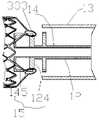
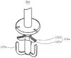
锁定件15包括设于推杆12远端的限位单元121和设于鞘芯14的连接单元141。限位单元121用于与连接单元141相配合地控制医疗器械30与输送装置10的相互连接与相互分离。请一并参阅图2,限位单元121包括皆固定在推杆121远端的第一限位件125和第二限位件123,其中,第二限位件123较第一限位件125靠近推杆121的远端。The locking
第二限位件123包括至少两个相互隔开的限位块124。每个限位块124的一端连接于推杆12,另一端从推杆12的表面朝远离推杆12的方向径向延伸。本实施例中,为了更清楚地显示限位块124、第一限位件125和连接单元141之间的位置关系和连接关系,限位块124仅有两个,呈条状,且两个限位块124位于推杆12的同一直径的延伸方向。The second limiting member 123 includes at least two limiting
可以理解的是,在其他实施例中,限位块124可以有多个,可以是除条状外的其他形状,但各限位块124之间设有供连接单元141相对第一限位件125运动的通道。例如,各限位块124可以相互隔开,相邻两限位块124之间的空隙形成所述通道;或者各限位块124靠近鞘芯14的中心轴的一端均与其相邻的限位块124靠近鞘芯14的中心轴的一端相接触且相连,以形成一体,但多个限位块124远离鞘芯14的中心轴的另一端相互隔开,例如所有限位块124配合形成类似于齿轮的形状,各轮齿之间的空隙形成所述通道。还可以理解的是,其他实施例中,根据实际需要,第二限位件123可以省略不要。It can be understood that, in other embodiments, there may be multiple limit blocks 124 , which may be other shapes than strips, but each
第一限位件125围绕推杆12,设有至少两个限位腔126。本实施例中,限位腔126为贯穿第一限位件125的近端表面和远端表面的通孔。在其他实施例中,限位腔126也可以从第一限位件125的部分侧面向第一限位件125的中心凹陷且贯穿第一限位件125的近端表面和远端表面;或者限位腔126为设在第一限位件125远端表面上的凹槽。限位腔126的个数与限位块124的个数相同。本实施例中,第一限位件125的外径大于第二限位件123的外径;第二限位件123在第一限位件125上的投影比限位腔126更靠近推杆12,且每个限位块124在第一限位件125上的投影与与其对应的限位腔126处于第一限位件125的同一直径上。The first limiting
连接单元141用于与第一限位件125相配合形成一个闭合的锁合空间17(参阅图4及图2),以防止医疗器械30在释放前从输送装置10上脱离,其包括至少两个连接件142。本实施例中,连接件142的个数与限位块124的个数和限位腔126的个数均相同,且每个连接件142与每个限位块124一一对应。每个连接件142均大致呈L形,包括径向杆143和轴向杆145,其中径向杆143的一端与鞘芯14相连,另一端远离鞘芯14且与同一连接件142的轴向杆145相连。多根径向杆143的组合即为连接单元141的径向连接部。锁合空间17是指,为了防止医疗器械30在释放前从输送装置10上脱离,轴向杆145与第一限位件125配合形成的空间,该空间由多根所述径向杆143的外侧表面相连形成的表面、多根轴向杆145的外侧表面相连形成的表面、与第一限位件125围合而成。每根轴向杆145一端均与同一连接件142的径向杆143远离鞘芯14的端部相连,另一端为自由端,且朝鞘芯14的近端延伸。每根轴向杆145的自由端均可活动地收容于相应的限位腔126中。在其他实施例中,径向杆143和轴向杆145的交汇处可设有圆滑的倒角。其他实施例中,多根径向杆143中相邻两根径向杆也可以相接触且相连形成一体,例如盘状结构,此时,该盘状结构即为连接单元141的径向连接部。The connecting
请一并参阅图2和图3-4,当轴向杆145的自由端收容于限位腔126内时,限位块124的自由端与轴向杆145接触,医疗器械30可挂在轴向杆145上,且位于轴向杆145、限位块124和第一限位件124围合的空间内,其无法从连接单元141上脱离。2 and 3-4, when the free end of the
请再次参阅图1,医疗器械30包括中空的主体部31和设于主体部31内的人工瓣叶(图未示)。主体部31是由金属丝编织或者管材切割且定型后而形成的网状结构,用于承载人工瓣叶。本实施例中,主体部31为采用镍钛金属管材切割且定型而成的网状结构。在其他实施例中,还可以采用镍钛丝编织且定型后形成支架主体,也可以采用由高分子材料制成的高分子丝例如聚碳酸酯丝、聚丙烯丝、聚酰胺丝编织或者由高分子材料制成的高分子管材切割且定型后形成支架主体。Please refer to FIG. 1 again, the
请一并参阅图1和图3,医疗器械30还包括多个与主体部31相连的连接部33。连接部33的个数小于或者等于连接件142的个数,以使每个连接部33均可以连接于一个连接件142上。本实施例中,连接部33的个数等于连接件142的个数。Please refer to FIG. 1 and FIG. 3 together, the
每个连接部33均包括两根与主体部31相连的连接条331和一个与两根连接条331的远离主体部31的端部相连的连接环333。Each connecting
当医疗器械30需放置于防钙化溶液中保存时,输送装置10与医疗器械30需分开包装。可在手术前利用装载器70,参照以下步骤将医疗器械30装载至输送装置10内部。首先,采用鞘管驱动件111驱动鞘管13相对推杆12向近端移动,直至锁定件15完全伸出鞘管13;其次,采用鞘芯驱动件113驱动鞘芯14相对推杆12向远端移动,移动的鞘芯14带动锁定件15的轴向杆145向远端移动,直至轴向杆145的自由端从限位腔126中完全退出,且限位块124与轴向杆145接触,处于轴向杆145的中间位置;接着,请参阅图3,将医疗器械30的多个连接环333逐个挂在相应的轴向杆145上;然后,采用鞘芯驱动件113驱动鞘芯14相对推杆12向近端移动,移动的鞘芯14带动连接单元121向近端移动,直至轴向杆145的自由端进入第一限位件125的相应的限位腔126中,如此实现医疗器械30与输送装置10的连接;最后,请参阅图4,将装载器50套至医疗器械30上,采用鞘管驱动件111驱动鞘管13相对推杆12向远端移动,并驱动装载器50随鞘管13向远端移动,直至医疗器械30可以完全以压缩状态收入鞘管13中,如图5所示。建好输送通道后,装载有医疗器械30的输送装置10的远端被输送至病灶附近位置。When the
可以理解的是,其他实施例中,限位块124的自由端与轴向杆145之间也可以有缝隙,此时,只要连接环333无法穿过该缝隙而进入挂有同一连接环333的轴向杆145、与同一轴向杆145相对应的限位块124、及径向连接部围合的空间内即可。It can be understood that, in other embodiments, there may also be a gap between the free end of the limiting
请参阅图6,当医疗器械30已到达病灶附近位置时,采用鞘管驱动件11驱动鞘管13相对推杆12慢慢地向近端移动。由于医疗器械30可自膨胀,在鞘管13向近端移动的过程中,鞘管13对医疗器械30的径向约束逐渐消失,医疗器械30逐渐从压缩状态往膨胀状态转变。待医疗器械30完全伸出鞘管13外,操作者观察医疗器械30是否已起到治疗作用。若医疗器械30的位置不理想,可使用鞘管驱动件11驱动鞘管13相对推杆12地向远端移动,医疗器械30再次被压缩至鞘管13内。调整医疗器械30位置,若有必要,重复以上步骤,直至医疗器械30达到理想的治疗效果。Referring to FIG. 6 , when the
待医疗器械30在病灶处达到预期的治疗效果,可再次采用鞘管驱动件11驱动鞘管13相对推杆12向近端移动,直至锁定件15从鞘管13中完全暴露出来。接着,请一并参阅图7至图9,采用鞘芯驱动件111驱动鞘芯14相对推杆12向远端移动,移动的鞘芯14带动轴向杆145相对限位块124向远端移动,即,连接环333在相应的限位块124的推动下相对轴向杆145向近端移动。当轴向杆145的自由端运动至与限位块124的外侧(即距离鞘芯14最远的一侧)的近端齐平时,即第一止挡件12c与第二止挡件14a相接触以阻挡轴向杆145相对限位块124继续向远端移动时,连接环333在限位块124的推动下会从轴向杆145的自由端处脱离。此时医疗器械30与输送装置10完全分离,如此,完成释放医疗器械30。正是由于因轴向杆145的自由端运动至与限位块124的外侧的近端齐平,在释放医疗器械30后,连接环333不会再次被轴向杆145勾住,保证了手术的安全性及顺畅性。After the
需要说明的是,本实施例中,请一并参阅图1,图2及图4,当轴向杆145与第一限位件125相配合形成锁合空间17时,第一止挡件12c的近端与第二止挡件14a的远端之间的在沿输送装置10的轴向上的距离等于轴向杆145的自由端与限位块124外侧的近端之间的在沿输送装置10的轴向上的距离,如此,当第一止挡件12c与第二止挡件14a相接触以阻挡轴向杆145相对限位块124继续向远端移动时,轴向杆145的自由端即可与限位块124外侧的近端齐平。It should be noted that, in this embodiment, please refer to FIG. 1 , FIG. 2 and FIG. 4 , when the
可以理解的是,其他实施例中,若当轴向杆145与第一限位件125相配合形成锁合空间17时,第一止挡件12c的近端与第二止挡件14a的远端之间的在沿输送装置10的轴向上的距离等于轴向杆145的自由端与限位块124外侧的远端之间的在沿输送装置10的轴向上的距离,如此,当第一止挡件12c与第二止挡件14a相接触以阻挡轴向杆145相对限位块124继续向远端移动时,轴向杆145的自由端即可与限位块124外侧的远端齐平;若当轴向杆145与第一限位件125相配合形成锁合空间17时,第一止挡件12c的近端与第二止挡件14a的远端之间的在沿输送装置10的轴向上的距离,大于轴向杆145的自由端与限位块124外侧的近端之间的在沿输送装置10的轴向上的距离,且小于轴向杆145的自由端与限位块124外侧的远端之间的在沿输送装置10的轴向上的距离,如此,当第一止挡件12c与第二止挡件14a相接触以阻挡轴向杆145相对限位块124继续向远端移动时,轴向杆145的自由端即可位于限位块124外侧的近端与远端之间。不论上述的哪种情况,只要释放医疗器械30后,轴向杆145的自由端不会再勾住医疗器械30即可。It can be understood that, in other embodiments, if the
可以理解的是,其他实施例中,当限位块124的自由端运动至与轴向杆145的外侧的远端齐平时,或者当限位块124的自由端运动至轴向杆145的外侧的远端与轴向杆145的外侧的近端之间时,第一止挡件12c与第二止挡件14a相接触以阻挡轴向杆145相对限位块124轴向移动,也可以防止连接环333再次被轴向杆145勾住,保证了手术的安全性及顺畅性。需要特别说明的是,若在植入医疗器械的过程中,仅通过手柄11来控制轴向杆145与限位块124之间的相对移动,因手柄在体外,而轴向杆145与限位块124均在体内,相距较远,故,手柄11很难精准地对轴向杆145与限位块124之间的相对的轴向移动进行操控,且操作者在操作手柄11时,若手打滑或者用力过大,均会导致较难精准操控轴向杆145与限位块124之间的相对的轴向移动,如此,加大了轴向杆145与限位块124脱离的可能性。而本实施例中,在推杆12和鞘芯14上分别设置与手柄11相分离的第一止挡件12c及第二止挡件14a,当第一止挡件12c及第二止挡件14a相接触时,轴向杆145与限位块124之间的轴向的相对移动即被制止,也就是说,通过设置第一止挡件12c及第二止挡件14a即可对轴向杆145与限位块124之间的轴向的相对移动作进一步的限制,增加了轴向杆145与限位块124之间的相对的轴向移动的操控的精准度,减小了轴向杆145与限位块124脱离可能性。It can be understood that, in other embodiments, when the free end of the limiting
在其他实施例中,连接单元141可以设于推杆12上,对应地,限位单元121设于鞘芯14上,且与连接单元141同轴,此时,锁定件15从近端至远端依次包括连接单元141、第二限位件123及第一限位件125,且连接单元141的轴向杆145的自由端朝向第一限位件125,即轴向杆145的自由端较连接单元141的径向连接部靠近第一限位件125;当连接单元141相对限位单元121轴向移动时,轴向杆145的自由端可与第一限位件125相配合,将器械30与输送装置10相连,轴向杆145的自由端也可与第一限位件125相分离,将器械30与输送装置10分离。需要说明的是,在本段所述的实施例中,当轴向杆145与第一限位件125相配合形成锁合空间17时,第一止挡件12c的近端与第二止挡件14a的远端之间的在沿输送装置10的轴向上的距离等于轴向杆145的自由端与限位块124外侧的远端之间的在沿输送装置10的轴向上的距离,如此,当第一止挡件12c与第二止挡件14a相接触以阻挡轴向杆145相对限位块124继续向近端移动时,轴向杆145的自由端即可与限位块124外侧的远端端齐平。可以理解的是,其他实施例中,若当轴向杆145与第一限位件125相配合形成锁合空间17时,第一止挡件12c的近端与第二止挡件14a的远端之间的在沿输送装置10的轴向上的距离等于轴向杆145的自由端与限位块124外侧的近端之间的在沿输送装置10的轴向上的距离,如此,当第一止挡件12c与第二止挡件14a相接触以阻挡轴向杆145相对限位块124继续向近端移动时,轴向杆145的自由端即可与限位块124外侧的近端齐平;若当轴向杆145与第一限位件125相配合形成锁合空间17时,第一止挡件12c的近端与第二止挡件14a的远端之间的在沿输送装置10的轴向上的距离,大于轴向杆145的自由端与限位块124外侧的远端之间的在沿输送装置10的轴向上的距离,且小于轴向杆145的自由端与限位块124外侧的近端之间的在沿输送装置10的轴向上的距离,如此,当第一止挡件12c与第二止挡件14a相接触以阻挡轴向杆145相对限位块124继续向近端移动时,轴向杆145的自由端即可位于限位块124外侧的近端与远端之间。不论上述的哪种情况,只要释放医疗器械30后,轴向杆145的自由端不会再勾住医疗器械30即可。In other embodiments, the connecting
可以理解的是,其他实施例中,若第一限位件125上并未设置限位腔126,而轴向杆145的自由端接触第一限位件125的端面时,也可以起到防止医疗器械30从输送装置10上脱离的目的。It can be understood that, in other embodiments, if the limiting
请参阅图10,当医疗器械30a为封堵器时,可通过设于其上的连接环301a与输送装置10相连,即能实现本发明的可控释放。Referring to FIG. 10 , when the
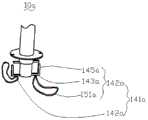
请参阅图11,本发明第二实施例提供的输送装置10a与输送装置10大致相同,不同之处在于,输送装置10a的连接单元141a不同于连接单元141a。具体地,连接单元141a的每个连接件142a除相连的径向杆143a和轴向杆145a之外,均还包括一个连接环151a。每个连接环151a的一端连接于相应的径向杆143的远端端面上,另一端均为自由端。Referring to FIG. 11 , the conveying device 10a provided by the second embodiment of the present invention is substantially the same as the conveying
请一并参阅图12,通过装载器(图未示)将医疗器械30装入输送装置10a内部的步骤包括:将每个连接环151a的自由端穿过医疗器械30的一个连接环333,且将连接有连接环333的连接环151a的自由端挂于输送装置10a的相应的轴向杆145a上。其他步骤与第一实施例中的装入步骤基本相同,不再赘述。12, the step of loading the
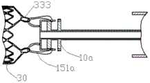
请参阅图13和图14,本发明第三实施例提供的输送装置10b与输送装置10基本相同,包括中空的推杆12b、鞘管13b、鞘芯14b和锁定件15b,不同之处在于,输送装置10b的锁定件15b具有不同于锁定件15的结构。Referring to FIGS. 13 and 14 , the
具体地,锁定件15b的限位单元121b的第一限位件125b的限位腔126b从第一限位件125b的部分侧面向第一限位件125b的中心凹陷且贯穿第一限位件125b的近端表面和远端表面;锁定件15b的连接单元141b的每个连接件142b均包括两个相对且平行的连接子件147b。Specifically, the limiting
每个连接子件147b均包括相连的径向杆143b和轴向杆145b。每个连接子件147b的径向杆143b的一端与鞘芯14b相连,另一端远离鞘芯14b且与同一连接子件147b的轴向杆145b相连;每个连接子件147b的轴向杆145b一端均与同一连接子件147b的径向杆143b远离鞘芯14b的端部相连,另一端(即自由端)朝鞘芯14b的近端延伸。Each connecting
每个连接件142b的两个轴向杆145b的自由端均可活动地收容于相应的限位腔126b中,以便于当限位单元121b与连接单元141b相配合来控制医疗器械30b与输送装置10b之间的连接时,医疗器械30b无法从连接单元141b上脱离。The free ends of the two
本实施例中,一个限位块124b对应于一个连接件142b的两根轴向杆145b;每个限位块124b的外径大于与同一限位块124b相应的两根轴向杆145b的内径,小于与同一限位块124b相应的两根轴向杆145b的外径,且每个限位块124b的周向厚度略小于其相应的两根轴向杆145b之间的周向距离,使得每个限位块124b的远离鞘芯14b的端部可以在其相应的连接件142b的两个轴向杆145b之间移动,而无法在轴向上移动,且每个限位块124b均可以收容于其相应的两根径向杆143b之间。In this embodiment, one
将医疗器械30b装入输送装置10b内部,包括以下步骤:首先,请参阅图14,将医疗器械30b的多个连接环333b逐个挂在相应的连接件142b的两根轴向杆145b上,且每个连接环333b均架设于相应的限位块124b上;其次,驱动鞘芯14b相对推杆12b向近端移动,移动的鞘芯14b带动连接单元121b向近端移动,直至轴向杆145b的自由端进入第一限位件125b的相应的限位腔126b中,且每根限位块124b均收容于相应的连接件142b的两个连接子件147b之间;最后,请参阅图15和图16,如第一实施例一样,将装载器50b套至医疗器械30b上,驱动鞘管13b相对推杆12b向远端移动,并驱动装载器随鞘管13b向远端移动,直至医疗器械30b可以完全以压缩状态收入鞘管13b中。Loading the
可以理解的是,本实施例中的推杆和鞘芯上也可以如第一实施例一样分别设有第一止挡件和第二止挡件,以防止医疗器械30释放后,轴向杆145b的自由端勾住医疗器械30。It can be understood that, as in the first embodiment, the push rod and the sheath core in this embodiment may also be provided with a first stopper and a second stopper, respectively, to prevent the axial rod after the release of the
当输送通道在人体中建好后,装载有医疗器械30b的输送装置10b的远端被送至病灶位置。请再次参阅图16及图17,当医疗器械30b已到达指定位置时,驱动鞘管13b(相对推杆12b慢慢地向近端移动。由于医疗器械30b可自膨胀,在鞘管13b向近端移动的过程中,鞘管13b对医疗器械30b的径向约束逐渐消失,医疗器械30b的连接环333b沿径向杆143b径向向外移动,医疗器械30b从压缩状态逐渐向膨胀状态转变。待到整个医疗器械30b完全伸出鞘管13b外,操作者观察医疗器械30是否已经充分发挥作用以和满足需求。若医疗器械30b位置不理想,驱动鞘管13b使得鞘管13b相对推杆12b地向远端移动,此过程中医疗器械30再次被压缩至鞘管13b内。调整医疗器械30b的位置,若必要可重复以上步骤,直至医疗器械30b达到理想的治疗效果。After the delivery channel is established in the human body, the distal end of the
待医疗器械30b在病灶处达到预期治疗效果,需再次驱动鞘管13b相对推杆12b向近端移动,直至整个锁定件15b完全暴露出来。接着,请一并参阅图18至图20,驱动鞘芯14b相对推杆12b向远端移动,移动的鞘芯14b带动连接件142b相对限位块124b向远端移动(即,连接环333b在限位块124b的推动下相对连接件142b向近端移动),直至连接件142的自由端从相应的限位腔126b中脱离,且连接环333b完全从连接件142b的轴向杆145b上脱离。此时医疗器械30b与输送装置10b的锁定件15b完全分离,如此,释放医疗器械30b的过程即完成。After the
由以上的结构描述、装载过程和植入过程可知,限位单元121b与连接单元141b相配合使用时,一方面,每个限位块124b的周向移动即被其相应的连接件142b所限制,防止了与限位块124b相连的医疗器械的连接环在周向上产生较大的扭曲,降低了医疗器械在周向上移位的可能性;另一方面,正是由于每个限位块124b均可以收容于其相应的连接件142b的两个径向杆143b之间,故,与限位块124b相连的医疗器械的连接环可以在相应的连接件142b的两个径向杆143b上移动,缓冲了医疗器械的向外膨胀力,降低了对人体的伤害。另外,每根限位块124b的周向厚度略小于其相应的连接件142b的两个轴向杆145b之间的距离,每根限位块124b可以填充其相应的连接件142b的两个轴向杆145b之间的空隙,从而可以防止释放后的医疗器械的连接环再次被轴向杆145b的自由端钩住,提高了医疗器械的释放效率。再者,采用本实施例中的锁定件15b来连接医疗器械的连接环时,医疗器械的连接环可挂于一个连接件142b的两个径向杆143b上,也就是说,医疗器械的连接环可以更靠近鞘芯14b的中心轴,故,采用本实施例中的输送装置10b收容的医疗器械可具有较小的压缩后的外径。It can be seen from the above structural description, loading process and implantation process that when the limiting
还需要说明的是,由于每根限位块124b均可以收容于其相应的连接件142b的两个径向杆143b之间,故,设计医疗器械30b的连接环的内径尺寸时,相比设计实施例一的医疗器械30b的连接环的内径尺寸而言,无需考虑限位块124b的尺寸对医疗器械30b的连接环的内径尺寸的影响。如此,即可相对地缩小医疗器械30b的连接环的内径尺寸。可以理解的是,在其他实施例中,若干连接件142b靠近若干连接件142b围成的内腔的内侧表面可以相连形成一个半球面,以便于医疗器械30b的连接环可以更顺畅地从径向移动转向轴向移动。还可以理解的是,其他实施例中,若干连接件142b远离若干连接件142b围成的内腔的外侧表面可以相连形成一个半球面,以便于加工制作。It should also be noted that, since each limiting
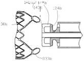
请参阅图21及22,本发明第四实施例的输送装置10c与输送装置10基本相同,包括中空的推杆12c、鞘管13c、鞘芯14c和锁定件15c,不同之处在于,输送装置10c的锁定件15c不同于锁定件15。21 and 22, the delivery device 10c according to the fourth embodiment of the present invention is basically the same as the
具体地,锁定件15c的第一限位件125c的限位腔126c为由部分第一限位件125c的侧面向第一限位件125c的中心凹陷且贯穿第一限位件125c的近端表面和远端表面的凹槽,且限位腔126c有三个。Specifically, the limiting
锁定件15c的第二限位件123c的每根限位块124c均包括两个相对且平行的卡合单元122c。Each limiting
锁定件15c的连接单元141c包括三个连接件142c,每个连接件142c均包括相连的径向杆143c和轴向杆145c。每个连接件142c的径向杆143c的一端与鞘芯14c相连,另一端远离鞘芯14c且与同一连接件142c的轴向杆145c相连;每个连接件142c的轴向杆145c一端均与同一连接件142c的径向杆143c远离鞘芯14c的端部相连,另一端(即自由端)朝鞘芯14c的近端延伸。每个连接件142c的轴向杆145c的自由端均可活动地收容于相应的限位腔126c中,以便于当限位单元121c与连接单元141c相配合来控制医疗器械30c与输送装置10c之间的连接时,医疗器械30c无法从连接单元141c上脱离。The connecting unit 141c of the locking piece 15c includes three connecting
优选地,本实施例中,一根轴向杆145c对应于一个限位块124c;每根轴向杆145c的外径均小于或者等于与其对应的限位块124d的外径;每根轴向杆145c的周向厚度均匀,且每根轴向杆145的周向厚度均略小于其相应的限位块124c的两个平行的卡合单元122c之间的周向距离,以便于每个连接件142a的径向杆143c和轴向杆145c中的每一个连接杆均可以活动地收容于相应的限位块的两个卡合单元122c之间。Preferably, in this embodiment, one axial rod 145c corresponds to one limiting
将医疗器械30a装入输送装置10a内部,包括以下步骤:首先,请参阅图24,将医疗器械30c的多个连接环333c逐个挂在相应的连接件142c的轴向杆145c上,且每个连接环333c均架设于相应的限位块124c上;其次,请参阅图23,驱动鞘芯14c相对推杆12c向近端移动,移动的鞘芯14c带动连接单元121c向近端移动,直至轴向杆145c的自由端进入第一限位件125c的相应的限位腔126c中,且每根径向杆143c均收容于相应的限位块124c的两个平行的卡合单元122c之间;最后,如第一实施例一样,将装载器(图未示)套至医疗器械30c上,驱动鞘管13c相对推杆12c向远端移动,并驱动装载器随鞘管13c向远端移动,直至医疗器械30c可以完全以压缩状态收入鞘管13c中。Loading the
当介入治疗的通道在人体中建好后,装载有医疗器械30c的输送装置10c的远端被送至病灶位置。当医疗器械30c已到达指定的病灶位置时,驱动鞘管13c相对推杆12c慢慢地向近端移动。请参阅图23及图24,由于医疗器械30c是可膨胀体,在鞘管13c向近端移动的过程中,鞘管13c对医疗器械30c的径向约束逐渐消失,医疗器械30c的连接环333c沿径向杆143c径向向外移动,医疗器械30c从压缩状态逐渐向膨胀状态转变。待到整个医疗器械30c完全伸出鞘管13c外,操作者通过使用X光或者超声等设备,观察医疗器械30c是否已经起到治疗效果。若医疗器械30c位置不理想,驱动鞘管13c相对推杆12c地向远端移动,此过程中医疗器械30c再次被压缩至鞘管13c内。调整医疗器械30c的位置,若有必要,重复以上过程,直至医疗器械30c达到理想的治疗效果。After the channel for interventional treatment is established in the human body, the distal end of the delivery device 10c loaded with the
请参阅图25和26,待医疗器械30c在病灶处效果达到预期,此时再次驱动鞘管13c相对推杆12c向近端移动,直至整个锁定件15c完全暴露出来。接着,驱动鞘芯14c相对推杆12c向远端移动,移动的鞘芯14c带动锁定件15c的连接件142c相对限位块124c向远端移动,即,连接环333c在限位块124c的推动下相对连接件142c向近端移动,直至连接环333c完全从连接件142c上脱离。此时医疗器械30c与输送装置10c的锁定件15c完全分离。如此,完成释放医疗器械30c。25 and 26, after the
由以上的结构描述、装载过程和植入过程可知,限位单元121c与连接单元141c相配合使用时,一方面,每个限位块124c的两个卡合单元122c的周向移动均即被其相应的连接件142c所限制,从而防止了与限位块124c相连的医疗器械的连接环在周向上产生较大的扭曲,降低了医疗器械在周向上移位的可能性;另一方面,正是由于每根径向杆143c均可以收容于其相应的限位块124c的两个卡合单元122c之间,故,与限位块124c相连的医疗器械的连接环可以在相应的径向杆143c上移动,缓冲了医疗器械的向外膨胀力,降低了对人体的伤害。另外,正是由于每根轴向杆145c的周向厚度略小于其相应的限位块124c的两个卡合单元122c之间的距离,每根轴向杆145c的自由端至少可以部分被其相应的限位块124c的两个卡合单元122c包覆,从而可以防止释放后的医疗器械的连接环再次被轴向杆145a的自由端钩住,提高了医疗器械的释放效率。再者,采用本实施例中的锁定件15c来连接医疗器械的连接环时,医疗器械的连接环可以挂于一根径向杆143c上,也就是说,医疗器械的连接环可以更靠近鞘芯14c的中心轴,故,采用本实施例中的输送装置10c收容的医疗器械可具有较小的压缩后的外径。It can be seen from the above structural description, loading process and implantation process that when the limiting unit 121c is used in conjunction with the connecting unit 141c, on the one hand, the circumferential movement of the two engaging units 122c of each limiting
在其他实施例中,限位腔126c的槽底还可以沿径向朝推杆12c继续延伸,也就是说,限位腔126c的径向长度可以等于或者略小于第一限位件125c的半径。在其他实施例中,相邻两个限位块124c中的相邻的两个卡合单元122c可以连接为一体,形成类似于第一限位件125c的结构,只要每个限位块124c的两个卡合单元122c之间的具有可以收容相应的连接件142c的空间即可。如此,多个限位块124c可以形成一个周面具有多个凹槽的推出盘,每个凹槽即为两个卡合单元122c之间的空隙。In other embodiments, the groove bottom of the limiting
在其他实施例中,所述鞘芯的远端还可以连接一个中空的从近端至远端逐渐变细的防损伤头,以防止鞘芯的远端在输送过程中损伤人体组织。In other embodiments, the distal end of the sheath core can also be connected with a hollow atraumatic head tapering from the proximal end to the distal end, so as to prevent the distal end of the sheath core from damaging human tissue during the delivery process.
请参阅图27,本发明第五实施例提供的输送装置10d,其与第三实施例中的输送装置10b基本相同,不同之处在于,本实施例的输送装置10d的连接件142d的两个连接子件147d的近端上架设一根止挡条148d,用于防止在释放医疗器械的过程中,限位块124d与相应的连接件142d相脱离,降低了限位块124d与和相应的连接件142d错位的风险,提高了医疗器械安装于输送装置10d上的效率。可以理解的是,正是由于止挡条148d的存在,本实施例的输送装置的推杆和鞘芯上可以无需分别设置第一止挡件和第二止挡件。Please refer to FIG. 27 , the conveying
可以理解的是,若将第一实施例中的轴向杆145上开设一个贯穿其内侧表面及外侧表面但未贯穿其自由端的端面的轴向通孔,且限位块124的自由端可以在该通孔中轴向滑动,则输送装置的推杆和鞘芯上也可以无需分别设置第一止挡件和第二止挡件。当然,可以理解的是,若需要设置多重止挡,本实施例中的推杆和鞘芯上也可以分别设置第一止挡件和第二止挡件,可以根据实际需要来设定。It can be understood that, if the
请参阅图28,本发明第六实施例提供的输送装置10e,其与第四实施例中的输送装置10c基本相同,不同之处在于,本实施例的输送装置10e的轴向杆145e的近端的周向厚度较同一轴向杆145e的其余部分的周向厚度厚,且轴向杆145e的近端的周向厚度大于与同一轴向杆145e相对应的限位块124e的两个卡合单元122e之间的周向距离,同一轴向杆145e的其余部分的周向厚度小于与同一轴向杆145e对应的所述限位块124e的两个推送单元122e之间的周向距离,如此,即可防止在释放医疗器械的过程中,限位块124e与相应的轴向杆145e相脱离,降低了限位块124e与和相应的轴向杆145e错位的风险,提高了医疗器械安装于输送装置10e上的效率。可以理解的是,正是由于的轴向杆145e的近端的周向长度较同一轴向杆145e的其余部分的周向长度长,且轴向杆145e的近端的周向长度大于与同一轴向杆145e相对应的限位块124e的两个卡合单元122e之间的周向距离,本实施例的输送装置的推杆和鞘芯上可以无需分别设置第一止挡件和第二止挡件。当然,可以理解的是,若需要设置多重止挡,本实施例中的推杆和鞘芯上也可以分别设置第一止挡件和第二止挡件,可以根据实际需要来设定。Referring to FIG. 28 , the
以上所述实施例的各技术特征可以进行任意的组合,为使描述简洁,未对上述实施例中的各个技术特征所有可能的组合都进行描述,然而,只要这些技术特征的组合不存在矛盾,都应当认为是本说明书记载的范围。The technical features of the above-described embodiments can be combined arbitrarily. For the sake of brevity, all possible combinations of the technical features in the above-described embodiments are not described. However, as long as there is no contradiction between the combinations of these technical features, All should be regarded as the scope described in this specification.
以上所述实施例仅表达了本发明的几种实施方式,其描述较为具体和详细,但并不能因此而理解为对发明专利范围的限制。应当指出的是,对于本领域的普通技术人员来说,在不脱离本发明构思的前提下,还可以做出若干变形和改进,这些都属于本发明的保护范围。因此,本发明专利的保护范围应以所附权利要求为准。The above-mentioned embodiments only represent several embodiments of the present invention, and the descriptions thereof are specific and detailed, but should not be construed as a limitation on the scope of the invention patent. It should be pointed out that for those of ordinary skill in the art, without departing from the concept of the present invention, several modifications and improvements can also be made, which all belong to the protection scope of the present invention. Therefore, the protection scope of the patent of the present invention should be subject to the appended claims.
Claims (19)
Translated fromChinesePriority Applications (4)
| Application Number | Priority Date | Filing Date | Title |
|---|---|---|---|
| CN201610518125.2ACN107550524B (en) | 2016-07-01 | 2016-07-01 | Conveying device |
| US16/311,282US10813756B2 (en) | 2016-07-01 | 2017-05-10 | Delivery device |
| EP17818945.2AEP3479800B1 (en) | 2016-07-01 | 2017-05-10 | Delivery device |
| PCT/CN2017/083723WO2018000948A1 (en) | 2016-07-01 | 2017-05-10 | Delivery device |
Applications Claiming Priority (1)
| Application Number | Priority Date | Filing Date | Title |
|---|---|---|---|
| CN201610518125.2ACN107550524B (en) | 2016-07-01 | 2016-07-01 | Conveying device |
Publications (2)
| Publication Number | Publication Date |
|---|---|
| CN107550524A CN107550524A (en) | 2018-01-09 |
| CN107550524Btrue CN107550524B (en) | 2020-01-03 |
Family
ID=60785863
Family Applications (1)
| Application Number | Title | Priority Date | Filing Date |
|---|---|---|---|
| CN201610518125.2AActiveCN107550524B (en) | 2016-07-01 | 2016-07-01 | Conveying device |
Country Status (4)
| Country | Link |
|---|---|
| US (1) | US10813756B2 (en) |
| EP (1) | EP3479800B1 (en) |
| CN (1) | CN107550524B (en) |
| WO (1) | WO2018000948A1 (en) |
Families Citing this family (24)
| Publication number | Priority date | Publication date | Assignee | Title |
|---|---|---|---|---|
| US8579964B2 (en) | 2010-05-05 | 2013-11-12 | Neovasc Inc. | Transcatheter mitral valve prosthesis |
| US9554897B2 (en) | 2011-04-28 | 2017-01-31 | Neovasc Tiara Inc. | Methods and apparatus for engaging a valve prosthesis with tissue |
| US9308087B2 (en) | 2011-04-28 | 2016-04-12 | Neovasc Tiara Inc. | Sequentially deployed transcatheter mitral valve prosthesis |
| US9345573B2 (en) | 2012-05-30 | 2016-05-24 | Neovasc Tiara Inc. | Methods and apparatus for loading a prosthesis onto a delivery system |
| US11406497B2 (en) | 2013-03-14 | 2022-08-09 | Jc Medical, Inc. | Heart valve prosthesis |
| US11259923B2 (en) | 2013-03-14 | 2022-03-01 | Jc Medical, Inc. | Methods and devices for delivery of a prosthetic valve |
| US9572665B2 (en) | 2013-04-04 | 2017-02-21 | Neovasc Tiara Inc. | Methods and apparatus for delivering a prosthetic valve to a beating heart |
| CA3007660A1 (en) | 2015-12-15 | 2017-06-22 | Neovasc Tiara Inc. | Transseptal delivery system |
| WO2017119013A1 (en)* | 2016-01-08 | 2017-07-13 | マツダ株式会社 | Negative pressure type actuator and engine gas-exhaustion device provided with negative pressure type actuator |
| US10433952B2 (en) | 2016-01-29 | 2019-10-08 | Neovasc Tiara Inc. | Prosthetic valve for avoiding obstruction of outflow |
| CA3042588A1 (en) | 2016-11-21 | 2018-05-24 | Neovasc Tiara Inc. | Methods and systems for rapid retraction of a transcatheter heart valve delivery system |
| CA3073834A1 (en) | 2017-08-25 | 2019-02-28 | Neovasc Tiara Inc. | Sequentially deployed transcatheter mitral valve prosthesis |
| AU2019205321A1 (en)* | 2018-01-07 | 2020-07-23 | Jc Medical, Inc. | Prosthetic heart valve delivery system |
| CN113271890B (en) | 2018-11-08 | 2024-08-30 | 内奥瓦斯克迪亚拉公司 | Ventricular deployment of transcatheter mitral valve prosthesis |
| CN111345926B (en)* | 2018-12-20 | 2021-06-15 | 先健科技(深圳)有限公司 | Conveying device and conveying system |
| CA3132873A1 (en) | 2019-03-08 | 2020-09-17 | Neovasc Tiara Inc. | Retrievable prosthesis delivery system |
| CA3135753C (en) | 2019-04-01 | 2023-10-24 | Neovasc Tiara Inc. | Controllably deployable prosthetic valve |
| US11491006B2 (en) | 2019-04-10 | 2022-11-08 | Neovasc Tiara Inc. | Prosthetic valve with natural blood flow |
| US11779742B2 (en) | 2019-05-20 | 2023-10-10 | Neovasc Tiara Inc. | Introducer with hemostasis mechanism |
| JP7520897B2 (en) | 2019-06-20 | 2024-07-23 | ニオバスク ティアラ インコーポレイテッド | Thin prosthetic mitral valve |
| EP4096578A1 (en)* | 2020-01-27 | 2022-12-07 | Biotronik AG | Catheter device comprising an overstroke stop mechanism and/or a re-sheathing limit mechanism |
| CN114081669B (en)* | 2020-08-25 | 2025-03-04 | 北京市普惠生物医学工程有限公司 | Artificial valves and valve delivery systems |
| CN114762631B (en)* | 2020-12-30 | 2025-09-02 | 先健科技(深圳)有限公司 | Stent graft and delivery device |
| US20230338175A1 (en)* | 2022-04-26 | 2023-10-26 | Accumedical Beijing Ltd. | Repositionable intracranial stent with retrieval mechanism |
Family Cites Families (25)
| Publication number | Priority date | Publication date | Assignee | Title |
|---|---|---|---|---|
| US8292943B2 (en)* | 2003-09-03 | 2012-10-23 | Bolton Medical, Inc. | Stent graft with longitudinal support member |
| US20080262590A1 (en)* | 2007-04-19 | 2008-10-23 | Medtronic Vascular, Inc. | Delivery System for Stent-Graft |
| CA2961053C (en)* | 2009-04-15 | 2019-04-30 | Edwards Lifesciences Cardiaq Llc | Vascular implant and delivery system |
| US20100268315A1 (en)* | 2009-04-17 | 2010-10-21 | Medtronic Vascular, Inc. | Castellated Sleeve Stent-Graft Delivery System and Method |
| HUE059497T2 (en)* | 2010-03-05 | 2022-11-28 | Edwards Lifesciences Corp | Support structures for heart valve prosthesis |
| US8764811B2 (en)* | 2010-04-20 | 2014-07-01 | Medtronic Vascular, Inc. | Controlled tip release stent graft delivery system and method |
| WO2011139746A1 (en) | 2010-04-27 | 2011-11-10 | Medtronic Inc. | Transcatheter prosthetic heart valve delivery device with passive trigger release |
| EP2618779B1 (en)* | 2010-09-24 | 2016-08-03 | Symetis SA | Stent valve and delivery apparatus |
| CN103635162B (en)* | 2011-06-30 | 2016-05-25 | 库克医学技术有限责任公司 | Spring controlled stent delivery system |
| EP2739247B1 (en)* | 2011-08-05 | 2018-10-10 | California Institute of Technology | Percutaneous heart valve delivery systems |
| US9579198B2 (en)* | 2012-03-01 | 2017-02-28 | Twelve, Inc. | Hydraulic delivery systems for prosthetic heart valve devices and associated methods |
| CA2875669C (en)* | 2012-07-12 | 2017-02-14 | Boston Scientific Scimed, Inc. | Low profile heart valve delivery system and method |
| US9649212B2 (en)* | 2012-08-30 | 2017-05-16 | Biotronik Ag | Release device for releasing a medical implant from a catheter and catheter comprising a release device |
| US9717595B2 (en)* | 2012-09-05 | 2017-08-01 | Medtronic Vascular Galway | Trans-aortic delivery system with containment capsule centering device |
| EP2710985A3 (en)* | 2012-09-20 | 2016-01-13 | Biotronik AG | Implant, system formed of an implant and a catheter, and method for producing such a system |
| FR2996748B1 (en)* | 2012-10-12 | 2015-02-06 | Cormove | DEVICE FOR TREATING A BLOOD CIRCULATION CONDUIT |
| CN202892148U (en)* | 2012-10-16 | 2013-04-24 | 北京迈迪顶峰医疗科技有限公司 | Support valve and conveying device thereof |
| CN104918652B (en)* | 2012-12-19 | 2019-05-17 | 玛芬股份有限公司 | A device and method for delivery of an intravascular filter |
| US9439796B2 (en)* | 2013-03-15 | 2016-09-13 | Cook Medical Technologies Llc | Prosthesis delivery device |
| EP2789313A3 (en)* | 2013-04-11 | 2015-01-28 | Biotronik AG | Insertion device, in particular a catheter, for inserting a medical hybrid implant, and also medical hybrid implant to be inserted by means of an insertion device |
| US9848880B2 (en)* | 2013-11-20 | 2017-12-26 | James E. Coleman | Adjustable heart valve implant |
| FR3023703B1 (en)* | 2014-07-17 | 2021-01-29 | Cormove | BLOOD CIRCULATION DUCT TREATMENT DEVICE |
| WO2016022673A1 (en)* | 2014-08-05 | 2016-02-11 | Dwyer Amy C | Anti-migration stent deployment delivery systems and methods |
| EP3054893B1 (en)* | 2014-09-24 | 2017-04-12 | Sorin Group Italia S.r.l. | A holder for heart valve prostheses, corresponding storage arrangement, delivery instrument and kit |
| CN109069282A (en)* | 2016-04-05 | 2018-12-21 | 波顿医疗公司 | Delivery system and application method with guide and distal sheath |
- 2016
- 2016-07-01CNCN201610518125.2Apatent/CN107550524B/enactiveActive
- 2017
- 2017-05-10EPEP17818945.2Apatent/EP3479800B1/enactiveActive
- 2017-05-10USUS16/311,282patent/US10813756B2/enactiveActive
- 2017-05-10WOPCT/CN2017/083723patent/WO2018000948A1/ennot_activeCeased
Also Published As
| Publication number | Publication date |
|---|---|
| US10813756B2 (en) | 2020-10-27 |
| CN107550524A (en) | 2018-01-09 |
| WO2018000948A1 (en) | 2018-01-04 |
| US20190183643A1 (en) | 2019-06-20 |
| EP3479800A4 (en) | 2019-12-18 |
| EP3479800A1 (en) | 2019-05-08 |
| EP3479800B1 (en) | 2022-03-16 |
Similar Documents
| Publication | Publication Date | Title |
|---|---|---|
| CN107550524B (en) | Conveying device | |
| CN108245292B (en) | Conveying device and conveying system | |
| US20240315839A1 (en) | Medical Device Delivery System and Methods of Delivering Medical Devices | |
| EP2720626B1 (en) | Anastomotic connector and system for delivery | |
| CN106913408B (en) | Transport system and intraluminal stent system | |
| CN103826569B (en) | Inversion delivery device for prostheses | |
| WO2018103662A1 (en) | Conveying system for implant | |
| CN108156803A (en) | pushable implant delivery system | |
| US8414640B2 (en) | Delivery system ejection component and method | |
| US8663302B2 (en) | Delivery system ejection component and method | |
| US20140012312A1 (en) | Jugular femoral vena cava filter system | |
| JP2013527010A5 (en) | ||
| US20240225812A1 (en) | Medical device | |
| CN109199660A (en) | A kind of medical conveying device and its transportation system | |
| CN109700575B (en) | Conveyors and Conveyor Systems | |
| US9974642B2 (en) | Expandable Vascular Sheath and Method of Use | |
| TW202011899A (en) | Braid implant delivery and retraction device with distal engagement | |
| WO2022252990A1 (en) | Filter and medical apparatus | |
| CN115005920A (en) | A plug spring coil | |
| CN114521993A (en) | Auxiliary device and conveyer | |
| WO2018129691A1 (en) | Recovery system for use with isolation device, and preloaded and postloaded intervention system | |
| CN113017911B (en) | Conveying system | |
| EP2777652A1 (en) | Loading tool for capturing stent points | |
| CN106890016B (en) | Recovery system for isolation device | |
| CN113116498B (en) | Ostomy appliance and ostomy system |
Legal Events
| Date | Code | Title | Description |
|---|---|---|---|
| PB01 | Publication | ||
| PB01 | Publication | ||
| SE01 | Entry into force of request for substantive examination | ||
| SE01 | Entry into force of request for substantive examination | ||
| GR01 | Patent grant | ||
| GR01 | Patent grant | ||
| TR01 | Transfer of patent right | ||
| TR01 | Transfer of patent right | Effective date of registration:20231226 Address after:518000 1604, Xianjian technology building, No. 22, Keji South 12th Road, gaoxinyuan community, Yuehai street, Nanshan District, Shenzhen, Guangdong Province Patentee after:Shenzhen Jianxin Medical Technology Co.,Ltd. Address before:518057 1st-5th Floor of Saiba Research Building, Langshan Second Road, North District of Nanshan High-tech Industrial Park, Shenzhen City, Guangdong Province Patentee before:LIFETECH SCIENTIFIC (SHENZHEN) Co.,Ltd. |