CN107530578B - rowing machine - Google Patents
rowing machineDownload PDFInfo
- Publication number
- CN107530578B CN107530578BCN201680023733.4ACN201680023733ACN107530578BCN 107530578 BCN107530578 BCN 107530578BCN 201680023733 ACN201680023733 ACN 201680023733ACN 107530578 BCN107530578 BCN 107530578B
- Authority
- CN
- China
- Prior art keywords
- rowing machine
- rowing
- user
- rail
- rocking
- Prior art date
- Legal status (The legal status is an assumption and is not a legal conclusion. Google has not performed a legal analysis and makes no representation as to the accuracy of the status listed.)
- Active
Links
Images


Classifications
- A—HUMAN NECESSITIES
- A63—SPORTS; GAMES; AMUSEMENTS
- A63B—APPARATUS FOR PHYSICAL TRAINING, GYMNASTICS, SWIMMING, CLIMBING, OR FENCING; BALL GAMES; TRAINING EQUIPMENT
- A63B22/00—Exercising apparatus specially adapted for conditioning the cardio-vascular system, for training agility or co-ordination of movements
- A63B22/0076—Rowing machines for conditioning the cardio-vascular system
- A—HUMAN NECESSITIES
- A63—SPORTS; GAMES; AMUSEMENTS
- A63B—APPARATUS FOR PHYSICAL TRAINING, GYMNASTICS, SWIMMING, CLIMBING, OR FENCING; BALL GAMES; TRAINING EQUIPMENT
- A63B21/00—Exercising apparatus for developing or strengthening the muscles or joints of the body by working against a counterforce, with or without measuring devices
- A63B21/00058—Mechanical means for varying the resistance
- A63B21/00069—Setting or adjusting the resistance level; Compensating for a preload prior to use, e.g. changing length of resistance or adjusting a valve
- A63B21/00072—Setting or adjusting the resistance level; Compensating for a preload prior to use, e.g. changing length of resistance or adjusting a valve by changing the length of a lever
- A—HUMAN NECESSITIES
- A63—SPORTS; GAMES; AMUSEMENTS
- A63B—APPARATUS FOR PHYSICAL TRAINING, GYMNASTICS, SWIMMING, CLIMBING, OR FENCING; BALL GAMES; TRAINING EQUIPMENT
- A63B21/00—Exercising apparatus for developing or strengthening the muscles or joints of the body by working against a counterforce, with or without measuring devices
- A63B21/00192—Exercising apparatus for developing or strengthening the muscles or joints of the body by working against a counterforce, with or without measuring devices using resistance provided by magnetic means
- A—HUMAN NECESSITIES
- A63—SPORTS; GAMES; AMUSEMENTS
- A63B—APPARATUS FOR PHYSICAL TRAINING, GYMNASTICS, SWIMMING, CLIMBING, OR FENCING; BALL GAMES; TRAINING EQUIPMENT
- A63B21/00—Exercising apparatus for developing or strengthening the muscles or joints of the body by working against a counterforce, with or without measuring devices
- A63B21/008—Exercising apparatus for developing or strengthening the muscles or joints of the body by working against a counterforce, with or without measuring devices using hydraulic or pneumatic force-resisters
- A63B21/0085—Exercising apparatus for developing or strengthening the muscles or joints of the body by working against a counterforce, with or without measuring devices using hydraulic or pneumatic force-resisters using pneumatic force-resisters
- A63B21/0088—Exercising apparatus for developing or strengthening the muscles or joints of the body by working against a counterforce, with or without measuring devices using hydraulic or pneumatic force-resisters using pneumatic force-resisters by moving the surrounding air
- A—HUMAN NECESSITIES
- A63—SPORTS; GAMES; AMUSEMENTS
- A63B—APPARATUS FOR PHYSICAL TRAINING, GYMNASTICS, SWIMMING, CLIMBING, OR FENCING; BALL GAMES; TRAINING EQUIPMENT
- A63B21/00—Exercising apparatus for developing or strengthening the muscles or joints of the body by working against a counterforce, with or without measuring devices
- A63B21/15—Arrangements for force transmissions
- A63B21/151—Using flexible elements for reciprocating movements, e.g. ropes or chains
- A63B21/153—Using flexible elements for reciprocating movements, e.g. ropes or chains wound-up and unwound during exercise, e.g. from a reel
- A—HUMAN NECESSITIES
- A63—SPORTS; GAMES; AMUSEMENTS
- A63B—APPARATUS FOR PHYSICAL TRAINING, GYMNASTICS, SWIMMING, CLIMBING, OR FENCING; BALL GAMES; TRAINING EQUIPMENT
- A63B21/00—Exercising apparatus for developing or strengthening the muscles or joints of the body by working against a counterforce, with or without measuring devices
- A63B21/15—Arrangements for force transmissions
- A63B21/151—Using flexible elements for reciprocating movements, e.g. ropes or chains
- A63B21/154—Using flexible elements for reciprocating movements, e.g. ropes or chains using special pulley-assemblies
- A—HUMAN NECESSITIES
- A63—SPORTS; GAMES; AMUSEMENTS
- A63B—APPARATUS FOR PHYSICAL TRAINING, GYMNASTICS, SWIMMING, CLIMBING, OR FENCING; BALL GAMES; TRAINING EQUIPMENT
- A63B21/00—Exercising apparatus for developing or strengthening the muscles or joints of the body by working against a counterforce, with or without measuring devices
- A63B21/15—Arrangements for force transmissions
- A63B21/157—Ratchet-wheel links; Overrunning clutches; One-way clutches
- A—HUMAN NECESSITIES
- A63—SPORTS; GAMES; AMUSEMENTS
- A63B—APPARATUS FOR PHYSICAL TRAINING, GYMNASTICS, SWIMMING, CLIMBING, OR FENCING; BALL GAMES; TRAINING EQUIPMENT
- A63B21/00—Exercising apparatus for developing or strengthening the muscles or joints of the body by working against a counterforce, with or without measuring devices
- A63B21/22—Resisting devices with rotary bodies
- A63B21/225—Resisting devices with rotary bodies with flywheels
- A—HUMAN NECESSITIES
- A63—SPORTS; GAMES; AMUSEMENTS
- A63B—APPARATUS FOR PHYSICAL TRAINING, GYMNASTICS, SWIMMING, CLIMBING, OR FENCING; BALL GAMES; TRAINING EQUIPMENT
- A63B21/00—Exercising apparatus for developing or strengthening the muscles or joints of the body by working against a counterforce, with or without measuring devices
- A63B21/40—Interfaces with the user related to strength training; Details thereof
- A63B21/4027—Specific exercise interfaces
- A63B21/4033—Handles, pedals, bars or platforms
- A63B21/4035—Handles, pedals, bars or platforms for operation by hand
- A—HUMAN NECESSITIES
- A63—SPORTS; GAMES; AMUSEMENTS
- A63B—APPARATUS FOR PHYSICAL TRAINING, GYMNASTICS, SWIMMING, CLIMBING, OR FENCING; BALL GAMES; TRAINING EQUIPMENT
- A63B22/00—Exercising apparatus specially adapted for conditioning the cardio-vascular system, for training agility or co-ordination of movements
- A63B22/16—Platforms for rocking motion about a horizontal axis, e.g. axis through the middle of the platform; Balancing drums; Balancing boards or the like
- A—HUMAN NECESSITIES
- A63—SPORTS; GAMES; AMUSEMENTS
- A63B—APPARATUS FOR PHYSICAL TRAINING, GYMNASTICS, SWIMMING, CLIMBING, OR FENCING; BALL GAMES; TRAINING EQUIPMENT
- A63B69/00—Training appliances or apparatus for special sports
- A63B69/06—Training appliances or apparatus for special sports for rowing or sculling
- A—HUMAN NECESSITIES
- A63—SPORTS; GAMES; AMUSEMENTS
- A63B—APPARATUS FOR PHYSICAL TRAINING, GYMNASTICS, SWIMMING, CLIMBING, OR FENCING; BALL GAMES; TRAINING EQUIPMENT
- A63B71/00—Games or sports accessories not covered in groups A63B1/00 - A63B69/00
- A63B71/06—Indicating or scoring devices for games or players, or for other sports activities
- A63B71/0619—Displays, user interfaces and indicating devices, specially adapted for sport equipment, e.g. display mounted on treadmills
- A63B71/0622—Visual, audio or audio-visual systems for entertaining, instructing or motivating the user
- A—HUMAN NECESSITIES
- A63—SPORTS; GAMES; AMUSEMENTS
- A63B—APPARATUS FOR PHYSICAL TRAINING, GYMNASTICS, SWIMMING, CLIMBING, OR FENCING; BALL GAMES; TRAINING EQUIPMENT
- A63B22/00—Exercising apparatus specially adapted for conditioning the cardio-vascular system, for training agility or co-ordination of movements
- A63B22/0025—Particular aspects relating to the orientation of movement paths of the limbs relative to the body; Relative relationship between the movements of the limbs
- A63B2022/0035—Upper limbs performing together the same movement, e.g. on a single support element
- A—HUMAN NECESSITIES
- A63—SPORTS; GAMES; AMUSEMENTS
- A63B—APPARATUS FOR PHYSICAL TRAINING, GYMNASTICS, SWIMMING, CLIMBING, OR FENCING; BALL GAMES; TRAINING EQUIPMENT
- A63B22/00—Exercising apparatus specially adapted for conditioning the cardio-vascular system, for training agility or co-ordination of movements
- A63B22/0025—Particular aspects relating to the orientation of movement paths of the limbs relative to the body; Relative relationship between the movements of the limbs
- A63B2022/0041—Particular aspects relating to the orientation of movement paths of the limbs relative to the body; Relative relationship between the movements of the limbs one hand moving independently from the other hand, i.e. there is no link between the movements of the hands
- A—HUMAN NECESSITIES
- A63—SPORTS; GAMES; AMUSEMENTS
- A63B—APPARATUS FOR PHYSICAL TRAINING, GYMNASTICS, SWIMMING, CLIMBING, OR FENCING; BALL GAMES; TRAINING EQUIPMENT
- A63B22/00—Exercising apparatus specially adapted for conditioning the cardio-vascular system, for training agility or co-ordination of movements
- A63B22/0076—Rowing machines for conditioning the cardio-vascular system
- A63B2022/0079—Rowing machines for conditioning the cardio-vascular system with a pulling cable
- A—HUMAN NECESSITIES
- A63—SPORTS; GAMES; AMUSEMENTS
- A63B—APPARATUS FOR PHYSICAL TRAINING, GYMNASTICS, SWIMMING, CLIMBING, OR FENCING; BALL GAMES; TRAINING EQUIPMENT
- A63B22/00—Exercising apparatus specially adapted for conditioning the cardio-vascular system, for training agility or co-ordination of movements
- A63B22/0076—Rowing machines for conditioning the cardio-vascular system
- A63B2022/0082—Rowing machines for conditioning the cardio-vascular system with pivoting handlebars
- A63B2022/0084—Rowing machines for conditioning the cardio-vascular system with pivoting handlebars pivoting about a horizontal axis
- A—HUMAN NECESSITIES
- A63—SPORTS; GAMES; AMUSEMENTS
- A63B—APPARATUS FOR PHYSICAL TRAINING, GYMNASTICS, SWIMMING, CLIMBING, OR FENCING; BALL GAMES; TRAINING EQUIPMENT
- A63B69/00—Training appliances or apparatus for special sports
- A63B69/06—Training appliances or apparatus for special sports for rowing or sculling
- A63B2069/062—Training appliances or apparatus for special sports for rowing or sculling by pulling on a cable
- A—HUMAN NECESSITIES
- A63—SPORTS; GAMES; AMUSEMENTS
- A63B—APPARATUS FOR PHYSICAL TRAINING, GYMNASTICS, SWIMMING, CLIMBING, OR FENCING; BALL GAMES; TRAINING EQUIPMENT
- A63B69/00—Training appliances or apparatus for special sports
- A63B69/06—Training appliances or apparatus for special sports for rowing or sculling
- A63B2069/064—Training appliances or apparatus for special sports for rowing or sculling with pivoting handlebars
- A—HUMAN NECESSITIES
- A63—SPORTS; GAMES; AMUSEMENTS
- A63B—APPARATUS FOR PHYSICAL TRAINING, GYMNASTICS, SWIMMING, CLIMBING, OR FENCING; BALL GAMES; TRAINING EQUIPMENT
- A63B69/00—Training appliances or apparatus for special sports
- A63B69/06—Training appliances or apparatus for special sports for rowing or sculling
- A63B2069/066—Training appliances or apparatus for special sports for rowing or sculling with handlebars rotating about a horizontal axis
- A—HUMAN NECESSITIES
- A63—SPORTS; GAMES; AMUSEMENTS
- A63B—APPARATUS FOR PHYSICAL TRAINING, GYMNASTICS, SWIMMING, CLIMBING, OR FENCING; BALL GAMES; TRAINING EQUIPMENT
- A63B69/00—Training appliances or apparatus for special sports
- A63B69/06—Training appliances or apparatus for special sports for rowing or sculling
- A63B2069/068—Training appliances or apparatus for special sports for rowing or sculling kayaking, canoeing
- A—HUMAN NECESSITIES
- A63—SPORTS; GAMES; AMUSEMENTS
- A63B—APPARATUS FOR PHYSICAL TRAINING, GYMNASTICS, SWIMMING, CLIMBING, OR FENCING; BALL GAMES; TRAINING EQUIPMENT
- A63B71/00—Games or sports accessories not covered in groups A63B1/00 - A63B69/00
- A63B71/0054—Features for injury prevention on an apparatus, e.g. shock absorbers
- A63B2071/0063—Shock absorbers
- A—HUMAN NECESSITIES
- A63—SPORTS; GAMES; AMUSEMENTS
- A63B—APPARATUS FOR PHYSICAL TRAINING, GYMNASTICS, SWIMMING, CLIMBING, OR FENCING; BALL GAMES; TRAINING EQUIPMENT
- A63B71/00—Games or sports accessories not covered in groups A63B1/00 - A63B69/00
- A63B71/06—Indicating or scoring devices for games or players, or for other sports activities
- A63B71/0619—Displays, user interfaces and indicating devices, specially adapted for sport equipment, e.g. display mounted on treadmills
- A63B2071/065—Visualisation of specific exercise parameters
- A—HUMAN NECESSITIES
- A63—SPORTS; GAMES; AMUSEMENTS
- A63B—APPARATUS FOR PHYSICAL TRAINING, GYMNASTICS, SWIMMING, CLIMBING, OR FENCING; BALL GAMES; TRAINING EQUIPMENT
- A63B21/00—Exercising apparatus for developing or strengthening the muscles or joints of the body by working against a counterforce, with or without measuring devices
- A63B21/00058—Mechanical means for varying the resistance
- A63B21/00069—Setting or adjusting the resistance level; Compensating for a preload prior to use, e.g. changing length of resistance or adjusting a valve
- A—HUMAN NECESSITIES
- A63—SPORTS; GAMES; AMUSEMENTS
- A63B—APPARATUS FOR PHYSICAL TRAINING, GYMNASTICS, SWIMMING, CLIMBING, OR FENCING; BALL GAMES; TRAINING EQUIPMENT
- A63B21/00—Exercising apparatus for developing or strengthening the muscles or joints of the body by working against a counterforce, with or without measuring devices
- A63B21/40—Interfaces with the user related to strength training; Details thereof
- A63B21/4027—Specific exercise interfaces
- A63B21/4033—Handles, pedals, bars or platforms
- A63B21/4034—Handles, pedals, bars or platforms for operation by feet
- A—HUMAN NECESSITIES
- A63—SPORTS; GAMES; AMUSEMENTS
- A63B—APPARATUS FOR PHYSICAL TRAINING, GYMNASTICS, SWIMMING, CLIMBING, OR FENCING; BALL GAMES; TRAINING EQUIPMENT
- A63B22/00—Exercising apparatus specially adapted for conditioning the cardio-vascular system, for training agility or co-ordination of movements
- A63B22/0087—Exercising apparatus specially adapted for conditioning the cardio-vascular system, for training agility or co-ordination of movements with a seat or torso support moving during the exercise, e.g. reformers
- A—HUMAN NECESSITIES
- A63—SPORTS; GAMES; AMUSEMENTS
- A63B—APPARATUS FOR PHYSICAL TRAINING, GYMNASTICS, SWIMMING, CLIMBING, OR FENCING; BALL GAMES; TRAINING EQUIPMENT
- A63B2208/00—Characteristics or parameters related to the user or player
- A63B2208/02—Characteristics or parameters related to the user or player posture
- A63B2208/0228—Sitting on the buttocks
- A63B2208/0238—Sitting on the buttocks with stretched legs, like on a bed
- A—HUMAN NECESSITIES
- A63—SPORTS; GAMES; AMUSEMENTS
- A63B—APPARATUS FOR PHYSICAL TRAINING, GYMNASTICS, SWIMMING, CLIMBING, OR FENCING; BALL GAMES; TRAINING EQUIPMENT
- A63B2209/00—Characteristics of used materials
- A63B2209/08—Characteristics of used materials magnetic
- A—HUMAN NECESSITIES
- A63—SPORTS; GAMES; AMUSEMENTS
- A63B—APPARATUS FOR PHYSICAL TRAINING, GYMNASTICS, SWIMMING, CLIMBING, OR FENCING; BALL GAMES; TRAINING EQUIPMENT
- A63B2210/00—Space saving
- A63B2210/50—Size reducing arrangements for stowing or transport
- A—HUMAN NECESSITIES
- A63—SPORTS; GAMES; AMUSEMENTS
- A63B—APPARATUS FOR PHYSICAL TRAINING, GYMNASTICS, SWIMMING, CLIMBING, OR FENCING; BALL GAMES; TRAINING EQUIPMENT
- A63B2220/00—Measuring of physical parameters relating to sporting activity
- A63B2220/20—Distances or displacements
- A—HUMAN NECESSITIES
- A63—SPORTS; GAMES; AMUSEMENTS
- A63B—APPARATUS FOR PHYSICAL TRAINING, GYMNASTICS, SWIMMING, CLIMBING, OR FENCING; BALL GAMES; TRAINING EQUIPMENT
- A63B2220/00—Measuring of physical parameters relating to sporting activity
- A63B2220/20—Distances or displacements
- A63B2220/24—Angular displacement
- A—HUMAN NECESSITIES
- A63—SPORTS; GAMES; AMUSEMENTS
- A63B—APPARATUS FOR PHYSICAL TRAINING, GYMNASTICS, SWIMMING, CLIMBING, OR FENCING; BALL GAMES; TRAINING EQUIPMENT
- A63B2220/00—Measuring of physical parameters relating to sporting activity
- A63B2220/30—Speed
- A—HUMAN NECESSITIES
- A63—SPORTS; GAMES; AMUSEMENTS
- A63B—APPARATUS FOR PHYSICAL TRAINING, GYMNASTICS, SWIMMING, CLIMBING, OR FENCING; BALL GAMES; TRAINING EQUIPMENT
- A63B2220/00—Measuring of physical parameters relating to sporting activity
- A63B2220/50—Force related parameters
- A63B2220/51—Force
- A63B2220/53—Force of an impact, e.g. blow or punch
- A—HUMAN NECESSITIES
- A63—SPORTS; GAMES; AMUSEMENTS
- A63B—APPARATUS FOR PHYSICAL TRAINING, GYMNASTICS, SWIMMING, CLIMBING, OR FENCING; BALL GAMES; TRAINING EQUIPMENT
- A63B2220/00—Measuring of physical parameters relating to sporting activity
- A63B2220/62—Time or time measurement used for time reference, time stamp, master time or clock signal
- A—HUMAN NECESSITIES
- A63—SPORTS; GAMES; AMUSEMENTS
- A63B—APPARATUS FOR PHYSICAL TRAINING, GYMNASTICS, SWIMMING, CLIMBING, OR FENCING; BALL GAMES; TRAINING EQUIPMENT
- A63B2225/00—Miscellaneous features of sport apparatus, devices or equipment
- A63B2225/09—Adjustable dimensions
- A—HUMAN NECESSITIES
- A63—SPORTS; GAMES; AMUSEMENTS
- A63B—APPARATUS FOR PHYSICAL TRAINING, GYMNASTICS, SWIMMING, CLIMBING, OR FENCING; BALL GAMES; TRAINING EQUIPMENT
- A63B2225/00—Miscellaneous features of sport apparatus, devices or equipment
- A63B2225/09—Adjustable dimensions
- A63B2225/093—Height
- A—HUMAN NECESSITIES
- A63—SPORTS; GAMES; AMUSEMENTS
- A63B—APPARATUS FOR PHYSICAL TRAINING, GYMNASTICS, SWIMMING, CLIMBING, OR FENCING; BALL GAMES; TRAINING EQUIPMENT
- A63B2225/00—Miscellaneous features of sport apparatus, devices or equipment
- A63B2225/10—Multi-station exercising machines
- A63B2225/105—Multi-station exercising machines each station having its own resisting device, e.g. for training multiple users simultaneously
- A63B2225/107—Resisting devices being of the same kind
- A—HUMAN NECESSITIES
- A63—SPORTS; GAMES; AMUSEMENTS
- A63B—APPARATUS FOR PHYSICAL TRAINING, GYMNASTICS, SWIMMING, CLIMBING, OR FENCING; BALL GAMES; TRAINING EQUIPMENT
- A63B2230/00—Measuring physiological parameters of the user
- A63B2230/75—Measuring physiological parameters of the user calorie expenditure
- A—HUMAN NECESSITIES
- A63—SPORTS; GAMES; AMUSEMENTS
- A63B—APPARATUS FOR PHYSICAL TRAINING, GYMNASTICS, SWIMMING, CLIMBING, OR FENCING; BALL GAMES; TRAINING EQUIPMENT
- A63B71/00—Games or sports accessories not covered in groups A63B1/00 - A63B69/00
- A63B71/06—Indicating or scoring devices for games or players, or for other sports activities
- A63B71/0619—Displays, user interfaces and indicating devices, specially adapted for sport equipment, e.g. display mounted on treadmills
Landscapes
- Health & Medical Sciences (AREA)
- General Health & Medical Sciences (AREA)
- Physical Education & Sports Medicine (AREA)
- Life Sciences & Earth Sciences (AREA)
- Biophysics (AREA)
- Orthopedic Medicine & Surgery (AREA)
- Cardiology (AREA)
- Vascular Medicine (AREA)
- Engineering & Computer Science (AREA)
- Multimedia (AREA)
- Human Computer Interaction (AREA)
- Rehabilitation Tools (AREA)
Abstract
Translated fromChinese
Description
Translated fromChinese技术领域technical field
本申请案涉及一种划船机及一种划船机系统。The present application relates to a rowing machine and a rowing machine system.
背景技术Background technique
划船机在家庭或健身房中通常用来模拟划船划艇的动作。划船机因健身及力量训练而受欢迎。划船机还由高级划手使用来进行除了水上训练之外的调理。Rowing machines are often used at home or in the gym to simulate the action of rowing a rowing boat. Rowing machines are popular for fitness and strength training. Rowing machines are also used by advanced rowers for conditioning in addition to water training.
划船机的实例是Concept

还已知,Concept
划船机是一种流行的运动形式,主要是因为其同时提供上肢、下肢及心血管锻炼。Rowing machines are a popular form of exercise primarily because they provide both upper, lower, and cardiovascular exercise.
发明内容SUMMARY OF THE INVENTION
根据第一方面,提供一种划船机,其包括:主体部分,其沿着纵轴从所述划船机的第一端延伸到所述划船机的第二端;座椅部分;拉手部分;所述座椅部分及所述拉手部分经配置以使用户能够在使用所述划船机期间模拟划船运动;其中所述划船机包括至少一个机构,其经配置以用于在使用所述划船机期间相对于所述纵轴向用户传送仰俯运动。According to a first aspect, there is provided a rowing machine comprising: a body portion extending along a longitudinal axis from a first end of the rowing machine to a second end of the rowing machine; a seat portion; a handle portion; the The seat portion and the handle portion are configured to enable a user to simulate rowing motion during use of the rowing machine; wherein the rowing machine includes at least one mechanism configured for relative movement during use of the rowing machine A pitch motion is transmitted to the user on the longitudinal axis.
根据一些实施例,所述至少一个机构进一步经配置以用于在使用所述划船机期间相对于所述纵轴向用户传送摇摆运动。According to some embodiments, the at least one mechanism is further configured for transmitting a rocking motion relative to the longitudinal axis to a user during use of the rowing machine.
根据一些实施例,所述划船机包括用于实现所述仰俯运动的仰俯机构及用于实现所述摇摆运动的摇摆机构。According to some embodiments, the rowing machine includes a pitch mechanism for implementing the pitch motion and a rocking mechanism for implementing the rocking motion.
根据一些实施例,所述仰俯机构包括弹簧及/或阻尼器布置。According to some embodiments, the pitch mechanism includes a spring and/or damper arrangement.
根据一些实施例,所述摇摆机构包括可旋转轴承组合件。According to some embodiments, the rocking mechanism includes a rotatable bearing assembly.
根据一些实施例,所述摇摆机构包括阻尼及/或限制摇摆的阻尼机构。According to some embodiments, the rocking mechanism includes a damping mechanism that damps and/or limits rocking.
根据一些实施例,所述摇摆机构的所述阻尼机构包括一或多个弹性缓冲块。According to some embodiments, the damping mechanism of the rocking mechanism includes one or more elastic bumpers.
根据一些实施例,所述至少一个机构包括所述划船机的所述第一端处的至少一个机构及所述划船机的所述第二端处的至少一个机构。According to some embodiments, the at least one mechanism includes at least one mechanism at the first end of the rowing machine and at least one mechanism at the second end of the rowing machine.
根据一些实施例,所述划船机的所述第一端处的所述至少一个机构包括仰俯机构及摇摆机构,且所述划船机的所述第二端处的所述至少一个机构包括仰俯机构及摇摆机构。According to some embodiments, the at least one mechanism at the first end of the rowing machine includes a pitch mechanism and a roll mechanism, and the at least one mechanism at the second end of the rowing machine includes a pitch mechanism Bend mechanism and swing mechanism.
根据一些实施例,所述划船机包括平行于所述纵轴延伸的轨部分,所述轨部分相对于所述划船机的所述主体部分悬挂在所述划船机的所述第一与第二端之间。According to some embodiments, the rowing machine includes a rail portion extending parallel to the longitudinal axis, the rail portion being suspended from the first and second portions of the rowing machine relative to the body portion of the rowing machine between the ends.
根据一些实施例,所述轨部分具有经配置以经安装接近于所述划船机的所述第一端的第一端,且所述轨部分具有经配置以经安装接近于所述划船机的所述第二端的第二端,所述轨部分包括所述轨部分的所述第一端与所述轨部分的所述第二端之间的槽部分。According to some embodiments, the rail portion has a first end configured to be mounted proximate the first end of the rowing machine, and the rail portion has a first end configured to be mounted proximate to the rowing machine The second end of the second end, the rail portion includes a slot portion between the first end of the rail portion and the second end of the rail portion.
根据一些实施例,所述轨部分相对于所述主体部分经由所述至少一个机构悬挂。According to some embodiments, the rail portion is suspended relative to the body portion via the at least one mechanism.
根据一些实施例,所述划船机包括踏板组合件。According to some embodiments, the rowing machine includes a pedal assembly.
根据一些实施例,所述划船机包括踏板组合件,所述踏板组合件连接到所述轨部分。According to some embodiments, the rowing machine includes a pedal assembly connected to the rail portion.
根据一些实施例,所述踏板组合件可滑动地连接到所述轨部分。According to some embodiments, the pedal assembly is slidably connected to the rail portion.
根据一些实施例,所述座椅部分可操作地连接到所述轨部分。According to some embodiments, the seat portion is operably connected to the rail portion.
根据一些实施例,所述座椅部分可在所述轨部分上滑动。According to some embodiments, the seat portion is slidable on the rail portion.
根据一些实施例,所述划船机包括安装到所述轨部分的另一轨部分,所述座椅部分可在所述另一轨部分上滑动。According to some embodiments, the rowing machine includes a further rail portion mounted to the rail portion on which the seat portion is slidable.
根据一些实施例,所述座椅部分及所述拉手部分中的至少一者可操作地连接到阻力机构。According to some embodiments, at least one of the seat portion and the handle portion is operably connected to a resistance mechanism.
根据一些实施例,所述阻力机构包括具有连接到中心轴件的一或多个叶片的飞轮。According to some embodiments, the resistance mechanism includes a flywheel having one or more vanes connected to a central shaft.
根据一些实施例,所述拉手部分经由齿轮机构可操作地连接到所述飞轮。According to some embodiments, the handle portion is operably connected to the flywheel via a gear mechanism.
根据一些实施例,所述齿轮机构包括第一齿轮及第二齿轮,及所述第一齿轮与所述第二齿轮之间的驱动连接,所述第一齿轮通过所述拉手部分的移动来驱动,且所述第二齿轮可操作地连接到所述飞轮的所述中心轴件,所述第二齿轮具有小于所述第一齿轮的半径的半径,使得在使用所述划船机期间所述第二齿轮及所述飞轮的旋转速度大于所述第一齿轮的旋转速度。According to some embodiments, the gear mechanism includes a first gear and a second gear, and a driving connection between the first gear and the second gear, the first gear being driven by movement of the handle portion , and the second gear is operatively connected to the central shaft member of the flywheel, the second gear having a radius less than the radius of the first gear such that during use of the rowing machine the first gear The rotation speed of the second gear and the flywheel is greater than the rotation speed of the first gear.
根据一些实施例,所述座椅部分及所述拉手部分中的至少一者可操作地连接到阻力机构,其中所述阻力机构包括具有连接到中心轴件的一或多个叶片的飞轮。According to some embodiments, at least one of the seat portion and the handle portion is operably connected to a resistance mechanism, wherein the resistance mechanism includes a flywheel having one or more blades connected to a central shaft.
根据一些实施例,所述一或多个叶片的半径小于所述中心轴件与所述轨部分的顶部表面之间的最小垂直距离。According to some embodiments, the radius of the one or more vanes is less than the minimum vertical distance between the central shaft member and the top surface of the rail portion.
根据一些实施例,所述拉手部分可与一或多个不同拉手部分互换。According to some embodiments, the handle portion is interchangeable with one or more different handle portions.
根据一些实施例,所述拉手部分包括至少一个橹部件。According to some embodiments, the handle portion includes at least one scull member.
根据一些实施例,所述拉手部分可在扫掠配置与匀浆配置之间互换。According to some embodiments, the handle portion is interchangeable between a sweeping configuration and a homogenizing configuration.
根据一些实施例,所述划船机包括用于向所述用户显示信息的显示器。According to some embodiments, the rowing machine includes a display for displaying information to the user.
根据一些实施例,所述显示器经配置以从所述机构接收信息,并显示与从所述至少一个机构接收到的所述信息有关的信息。According to some embodiments, the display is configured to receive information from the facility and to display information related to the information received from the at least one facility.
根据一些方面,提供一种划船机系统,其包括:如第一方面中陈述的串联连接的两个或两个以上划船机。According to some aspects, there is provided a rowing machine system comprising: two or more rowing machines connected in series as set forth in the first aspect.
根据第三方面,提供一种划船机,其包括:主体部分,其从所述划船机的第一端纵向延伸到所述划船机的第二端,以便界定所述划船机的纵轴;座椅部分;第一拉手部分;第二拉手部分;所述座椅部分及所述第一及第二拉手部分经配置以使用户能够在使用所述划船机期间模拟划船运动;所述第一拉手部分可操作地连接到第一阻力机构,且所述第二拉手部分可操作地连接到第二阻力机构。According to a third aspect, there is provided a rowing machine comprising: a body portion extending longitudinally from a first end of the rowing machine to a second end of the rowing machine so as to define a longitudinal axis of the rowing machine; a seat a seat portion; a first handle portion; a second handle portion; the seat portion and the first and second handle portions are configured to enable a user to simulate rowing motion during use of the rowing machine; the first handle The portion is operably connected to the first resistance mechanism, and the second pull handle portion is operably connected to the second resistance mechanism.
根据一些实施例,所述第一及第二阻力机构的相应阻力可独立地调整。According to some embodiments, the respective resistances of the first and second resistance mechanisms are independently adjustable.
根据一些实施例,所述第一及第二拉手部分可附接到彼此且可从彼此卸离。According to some embodiments, the first and second handle portions are attachable to and detachable from each other.
根据一些实施例,所述第一及第二拉手部分包括橹部件。According to some embodiments, the first and second handle portions include scull members.
根据一些实施例,所述第一及第二拉手部分用相应第一及第二缆线连接到其相应第一及第二阻力机构。According to some embodiments, the first and second handle portions are connected to their respective first and second resistance mechanisms with respective first and second cables.
根据一些实施例,所述第一阻力机构包括第一飞轮,且所述第二阻力机构包括第二飞轮。According to some embodiments, the first resistance mechanism includes a first flywheel and the second resistance mechanism includes a second flywheel.
根据第四方面,提供一种划船机,其包括:主体部分,其沿着纵轴从所述划船机的第一端延伸到所述划船机的第二端;座椅部分及拉手部分,其经配置以使用户能够在使用所述划船机期间模拟划船运动;其中所述划船机包括至少一个机构,其经配置以用于在使用所述划船机期间相对于所述纵轴向用户传送仰俯运动及摇摆运动中的至少一者。According to a fourth aspect, there is provided a rowing machine comprising: a body portion extending along a longitudinal axis from a first end of the rowing machine to a second end of the rowing machine; a seat portion and a handle portion, which is configured to enable a user to simulate rowing motion during use of the rowing machine; wherein the rowing machine includes at least one mechanism configured to transmit pitch to the user relative to the longitudinal axis during use of the rowing machine at least one of a pitch motion and a rocking motion.
根据第五方面,提供一种基本上如本文关于附图所描述的划船机。According to a fifth aspect, there is provided a rowing machine substantially as herein described with respect to the accompanying drawings.
附图说明Description of drawings
图1A及1B展示根据实施例的呈一种配置的划船机;1A and 1B show a rowing machine in one configuration, according to an embodiment;
图2A及2B展示根据实施例的呈另一配置的划船机;2A and 2B show a rowing machine in another configuration, according to an embodiment;
图3A及3B展示根据另一实施例的划船机;3A and 3B show a rowing machine according to another embodiment;
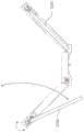
图4A展示根据实施例的划船机的摇摆功能性;4A shows rocking functionality of a rowing machine according to an embodiment;
图4B展示根据实施例的划船机的仰俯功能性;4B shows pitch functionality of a rowing machine according to an embodiment;
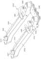
图5A展示根据实施例的连结在一起的两个划船机;5A shows two rowing machines linked together, according to an embodiment;
图5B更详细地展示根据实施例的用于连结两个或两个以上划船机的机构;5B shows in more detail a mechanism for joining two or more rowing machines, according to an embodiment;
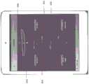
图6A到6D展示根据实施例的用户接口显示器;6A-6D show a user interface display according to an embodiment;
图7A及7B展示根据另一实施例的连结在一起的两个划船机;7A and 7B show two rowing machines linked together according to another embodiment;
图8展示根据实施例的其中其橹在收起位置中的划船机;8 shows a rowing machine with its scull in a stowed position, according to an embodiment;
图9到11B更详细地展示根据实施例的摇摆机构;9-11B show a rocking mechanism according to an embodiment in more detail;
图12到17展示根据实施例的划船机的阻尼机构;12-17 show a damping mechanism of a rowing machine according to an embodiment;
图18A及18B展示根据实施例的划船机的拉手组合件;18A and 18B show a pull handle assembly for a rowing machine according to an embodiment;
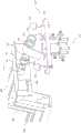
图19到21展示根据另一实施例的划船机;19-21 show a rowing machine according to another embodiment;
图22到24展示根据另一实施例的划船机;22-24 show a rowing machine according to another embodiment;
图25展示根据实施例的划船机的计算机硬件;25 shows computer hardware of a rowing machine according to an embodiment;
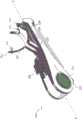
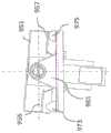
图26是根据实施例的划船机的等距视图;26 is an isometric view of a rowing machine according to an embodiment;
图27是根据实施例的划船机的侧视图;27 is a side view of a rowing machine according to an embodiment;
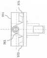
图28是根据呈第一配置的实施例的前减震器机构的侧视图;28 is a side view of the front shock absorber mechanism according to the embodiment in the first configuration;
图29是呈第二配置的图28的减震器的侧视图;Figure 29 is a side view of the shock absorber of Figure 28 in a second configuration;
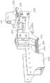
图30是根据呈第一配置的实施例的后减震器机构的侧视图;30 is a side view of the rear shock absorber mechanism according to the embodiment in the first configuration;
图31是呈第二配置的图30的减震器的侧视图;Figure 31 is a side view of the shock absorber of Figure 30 in a second configuration;
图32是根据呈第一配置的实施例的摇摆机构的等距视图;32 is an isometric view of a rocking mechanism according to an embodiment in a first configuration;
图33是呈第二配置的图32的摇摆机构的等距视图;Figure 33 is an isometric view of the rocking mechanism of Figure 32 in a second configuration;
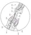
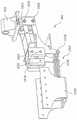
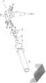
图34是根据实施例的踏板及飞轮组合件的等距视图;34 is an isometric view of a pedal and flywheel assembly according to an embodiment;
图35是根据实施例的划船机的示意图。35 is a schematic diagram of a rowing machine according to an embodiment.
具体实施方式Detailed ways
图1A及1B展示根据实施例的划船机100。所述划船机包括在纵向方向上,即,沿着图1A中的轴X-X延伸的主体部分102。所述划船机包括第一或前部104,及第二或后部106。座椅部分108经定位朝向所述划船机的后部106。座椅部分108可移动地安装于轨部分147上,在使用划船机期间,座椅部分108可沿着轨部分147来回(即,在平行于X轴的方向上)滑动。轨部分及/或座椅可包括限制座椅108的整体移动的前及后挡块。在一些实施例中,挡块的位置可由用户调整。座椅部分108可在其下侧上包括轮以使座椅部分能够在轨147上行进。所述轮可自清洁。替代地,所述座椅可被固定在适当位置中,且踏板组合件132(下文进行更详细解释)在划船运动期间来回滑动。术语“轨”可与术语“横梁”或“单轨”或类似物互换地使用。1A and 1B show a
还提供拉手部分112。在此实例中,拉手部分112形状为基本上椭圆形,在手柄部分116与118之间具有间隙114。当然,应了解,这仅是举实例,且在其它实施例中可提供其它拉手形状。A
缆线120及122可操作地将拉手部分112连接到定位在划船机的后部处的阻力机构124。在此实施例中,阻力机构包括对抗空气阻力的飞轮。在其它实施例中,飞轮可对抗磁阻力或水阻力。在实施例中,可调整阻力机构的阻力。在图1A的实例中,阻力通过移动杠杆126来调整,这在冲程的驱动阶段期间增加或减小空气阻力。在125处展示阻力机构的空气出口。
应了解,所描述的实施例是示范性的,且在其它实施例中,可使用任何种类的阻力机构。It should be appreciated that the described embodiments are exemplary and that in other embodiments, any kind of resistance mechanism may be used.
在一个实施例中,提供单个阻力机构,缆线120及122两者都可操作地连接到单个阻力机构。在另一实施例中,提供两个独立阻力机构,缆线120及122可操作地单独连接到所述独立阻力机构。这使缆线120及122两者能够完全独立进行操作。这关于图2A及2B更详细地进行描述。In one embodiment, a single resistance mechanism is provided to which both
在图1A及1B的实施例中,座椅在轨部分147上自由滑动,即,其未连接到阻力机构。在其它实施例中,座椅部分108也可连接到阻力机构124。此可为连接到缆线120及122中的一者或两者的相同阻力机构,或可提供另一阻力机构以在座椅部分108上独立地行动。In the embodiment of Figures 1A and 1B, the seat slides freely on the
在图1A的实例中,臂128及130提供缆线120及122到划船机的附接点。缆线120及122在这些臂部128及130内被引向阻力机构124。In the example of FIG. 1A,
还提供踏板组合件132,其包括踏板部分134及136。在此实施例中,踏板组合件132是整体构造,其上附接有踏板部分134及136。踏板132及/或轨部分145还可包括前及后挡块以限制踏板132在轨部分145上的整体移动。在一些实施例中,后挡块的位置可由用户调整。在其它实施例中,无需调整轨上的挡块,因为位置是由用户的腿的长度来指定。在一些实施例中,还可调整踏板132的高度(即,在相对于地面的上下方向上)。在一些实施例中,踏板134及136能够相对于踏板组合件132来回移动以适应不同用户的体型,并保证定位是准确的。在一些实施例中,踏板可在轨组合件上滑动。在一些实施例中,踏板附接到阻力机构。A
在此实施例中,臂128及130各自连接到踏板组合件132。第一销138将臂128连接到踏板组合件132。第二销140将臂130连接到踏板组合件132。销138及140两者具有锁定及解锁位置,以便选择性地将臂128及130锁定到踏板组合件132及解锁臂128及130。此使臂128及130能够在销处于解锁位置中时进行旋转。这可在下文关于图2A的描述中得到更完全的了解。In this embodiment,
划船机100还包括显示器141上的用户接口142。显示器141可为LCD屏幕或任何其它类型的显示器。显示器141可包括用于将信息或命令输入到划船机的硬件按钮。显示器141可另外/替代地包括触摸屏显示器。
在图1A中,未展示用户,以使图的清晰度最大化。然而,应理解,拉手部分112的位置及缆线120及122中的张力表示在划船运动的冲程阶段期间用户朝向用户自身拉动拉手112。In Figure 1A, the user is not shown to maximize the clarity of the figure. It should be understood, however, that the location of the
在图1A的实施例中,踏板组合件132可沿着轨部分145移动。在图1A及1B的实施例中,轨部分147及145垂直间隔开,且由倾斜部分149连接。这可在图4A中得到更完全的了解。部分145、147及149可为轨的整体构造的部分。在另一实施例中,部分145、147及149是用适当连接器/支架连接的分离轨部分。在其它实施例中,可省略倾斜部分149,在这种情况下,轨145与147分离。在另一实施例中,可提供单个笔直轨部分,在这种情况下,座椅部分108及踏板组合件132将被定位在相同水平面处。In the embodiment of FIG. 1A ,
图1B展示在划船运动阶段的不同点处的图1A的划船机100(为更清楚起见,再一次未展示用户)。在图1B中,踏板组合件132已沿着轨145朝向划船机的后部106移动。拉手部分112已朝向臂128及130移动,且缆线120及122已经回缩到臂128及130中。尽管座椅部分108可在轨147上移动,但座椅部分108已经保持在基本上静止的位置。为清楚起见,在图1B中再一次未展示用户。然而,座椅部分108、踏板组合件132及拉手部分112的位置表示划船冲程的恢复阶段的结束/驱动阶段的开始。FIG. 1B shows the
图2A及2B展示根据另一实施例的划船机200。按照图1A及1B,划船机200包括主体部分202、座椅部分208、阻力机构224、前端204及后端206。除另有明确描述外,来自图1A及1B的实施例的特征可以任何方式与图1A及图2B的实施例组合。为简明起见,此处仅详细描述实施例之间的主要差异。2A and 2B show a
臂228及230连接到踏板组合件232。在一些实施例中,此连接是借助于一或多个快速释放串来实现快速地将臂组装到踏板及快速地拆离臂。
如从图2A可见,拉手部分212包括两个分离拉手215及217。拉手215包括手柄部分216,且拉手217包括手柄部分218。拉手215经由缆线220及臂228可操作地连接到阻力机构224。拉手217经由缆线222及臂230可操作地连接到阻力机构224。As can be seen from FIG. 2A , the
与图1A及图1B的臂128及130相比,在图2A的实施例中,臂228及230已向外旋转。箭头A及B展示可如何向内及向外旋转臂228及230。此举通过选择性地解锁及锁定销238及240来协助。与图1A及1B相比,通过如图2A中展示那样向外旋转臂228及230,点221(缆线220第一次与臂228相遇之处)与点223(缆线222第一次与臂230相遇之处)之间的距离增加。此距离可通过臂的旋转而进一步增加或减小。此可调整性使用户能够调整拉手位置。此可允许用户复制特定划船位置,或可使用户的拉手位置更舒适,或可使用户的不同肌肉群用力。在一个实施例中,摆臂128及130可相对于轨145的纵轴旋转大约50度(且更特定来说,49.5度)的角度。这些角度被视为给予与划船/匀浆拉手的感觉类似的感觉。Compared to
在一些实施例中,拉手215及217可附接到彼此以提供与图1A及1B中的拉手112相同或类似的拉手。此可通过将拉手215的端246附接到拉手217的端248来完成。可使用任何类型的连接,例如螺丝配件、摩擦配件等等。In some embodiments, pull
在图2A的实施例中,阻力机构224包括第一阻力机构224A及第二阻力机构224B。举例来说,阻力机构224A及224B可各自包括飞轮。拉手215可操作地连接到飞轮224A,且拉手217可操作地连接到飞轮224B。飞轮224A及224B的阻力可独立地调整。举例来说,用户可将一个飞轮上的阻力设置为大于另一飞轮上的阻力。用户可利用此功能以便集中加强其身体的特定侧。In the embodiment of FIG. 2A , the
为清楚起见,在图2A中再一次未展示用户。然而,应了解,拉手215及217的位置及可移动踏板组合件232的位置表示划船冲程的驱动阶段的结束/划船冲程的恢复阶段的开始。For clarity, the user is again not shown in Figure 2A. It should be appreciated, however, that the position of the pull handles 215 and 217 and the position of the
图2B展示不同划船循环阶段期间的划船机200。在图2B中,缆线220回缩于臂228中,且缆线222回缩于臂230中。因此,拉手215接近附接点221,且拉手217接近附接点223。FIG. 2B shows
此外,在图2B中,踏板组合件232已向后沿着轨245朝向划船机的后端206滑动。座椅、踏板组合件232、及拉手215及217的位置表示划船冲程的恢复阶段的结束/划船冲程的驱动阶段的开始。Additionally, in Figure 2B,
尽管在图中未展示,但应了解,踏板可包括使用户能够将其脚捆绑到踏板的皮带或类似物。在此实施例中,踏板组合件232可在轨245上滑动,且借助于缆线连接到阻力机构。此在腿驱动期间向用户提供阻力。在其它实施例中,踏板可相对于划船机200的主体202固定,即,使得踏板不能在轨245上滑动。此实施例可能需要延长轨147,以为座椅部分108提供充分行进。因此,实施例可提供以下各项中的一或多者:固定座椅及移动踏板;移动座椅及固定踏板;移动座椅及移动踏板。在一些实施例中,划船机可在这些配置中的任何者之间调整。Although not shown in the figures, it should be understood that the pedals may include straps or the like that enable a user to tie their feet to the pedals. In this embodiment,
尽管图中未展示,但缆线卷取组合件可被包括于划船机的主体202中以在必要时在冲程及/或恢复阶段期间卷取缆线120/220及122/222。缆线卷取机构可被并入于阻力机构124/224中。Although not shown in the figures, a cable take-up assembly may be included in the
尽管被描述为两个分离实施例,但图1A及1B的配置和图2A及2B的配置可由相同划船机提供。即,图1A及1B的拉手部分可经分离以提供图2A及2B的两个拉手部分,且图1A及1B的臂128及130可摆动到图2A及2B的配置。Although described as two separate embodiments, the configuration of FIGS. 1A and 1B and the configuration of FIGS. 2A and 2B may be provided by the same rowing machine. That is, the handle portion of Figs. 1A and 1B can be separated to provide the two handle portions of Figs. 2A and 2B, and the
图3A及3B展示具有替代帆装设计的实施例。如图3A中所展示,划船机300包括帆装组合件350。在图3A及3B的实施例中,帆装组合件350经固定以用于移动到踏板组合件332。帆装组合件350包括附接到交叉部件356的第一橹部件352及第二橹部件354。橹部件352包括手柄部分353,且橹部件354包括手柄部分355。3A and 3B show embodiments with alternative sail designs. As shown in FIG. 3A ,
交叉部件356被固定到踏板组合件332的上部处的踏板组合件332。橹部件352用连杆组358附接到交叉部分356。橹部件354用连杆组360附接到交叉部件356。连杆组358及360使橹部件能够在X、Y及Z方向上移动,以及使橹能够围绕其纵轴旋转。连杆组358及360可包括例如通用接合点。连杆组358及360及其提供的运动角度使用户能够使橹部件“顺浆”及“直浆”,并在冲程期间分别在提取及放置橹时复制“轻拍”及“举起手”以准确地重新创建水上划船运动。
图3A及3B的双橹配置表示划艇“匀浆”配置。在另一实施例中,橹部件的配置可经改变以提供“扫掠”配置(参见图7B)。The double scull configuration of Figures 3A and 3B represents a rowboat "homogenization" configuration. In another embodiment, the configuration of the scull member may be altered to provide a "swept" configuration (see Figure 7B).
如图3A中所展示,连杆组360定位于狭槽362中。此使连杆组360的位置能够在狭槽362内调整,从而允许用户精细调谐橹部件354的准确位置及角度。等效狭槽也被设置在橹352的交叉部件356的另一侧上,以同样实现那个橹部件的精细调谐调整。在一些实施例中,连杆组360可使用帆装销或类似物被固定在狭槽362中的适当位置中。接着,一旦安装好,帆装销就不会再移动,并且已开始划船,那么。在其它实施例中,可移除狭槽360,且连杆组358及360以那种方式被固定在适当位置中。As shown in FIG. 3A , linkage set 360 is positioned in
橹部件352由缆线320可操作地连接到阻力机构324。橹部件354由缆线322可操作地连接到阻力机构324。如先前所论述,阻力机构324可针对每一橹部件而包括独立阻力机构。缆线320经由缆线引导件364而被引向阻力机构324。缆线322经由缆线引导件366而被引向阻力机构324。缆线引导件364及366帮助维持缆线320及322中的张力。The
为清楚起见,图3A中再一次未展示用户。在图3A中,橹352及354、踏板组合件332及座椅308的位置表示划船运动的冲程阶段的结束,即,其中朝向用户的上肢拉动手柄部分353及355,且远离用户的上肢推动踏板组合件332。For clarity, the user is again not shown in Figure 3A. In Figure 3A, the positions of
图3B展示在表示划船运动的恢复阶段的结束的位置中的划船机300,即,其中远离用户的上肢推动橹的拉手部分353及355,且朝向用户的上肢拉动踏板组合件332。从图3B还应了解,缆线引导件364及366可分别围绕交叉部件356在与橹部件352及354相同的弧上旋转,以承受缆线320及322中的张力。3B shows
在一些实施例中,橹部件352及354的长度可经调整以复制匀浆橹以及扫掠橹的长度。橹部件可包括用于调整其长度的伸缩机构。In some embodiments, the lengths of
在实施例中,划船机的元件可仰俯(或换句话来说,倾斜)及/或摇摆以向用户传送仰俯及/或摇摆运动,如图4A及4B中所展示。In an embodiment, elements of the rowing machine may pitch (or in other words, tilt) and/or roll to convey pitch and/or roll motions to the user, as shown in Figures 4A and 4B.
如图4A中所展示,划船机400包括整体轨部分或单轨444,其从划船机的前端404朝向划船机的后端406延伸。踏板组合件432及座椅部分408两者经配置以沿着平行于纵轴X-X的单轨444来回滑动。踏板组合件432经配置以在单轨444的第一部分445上滑动,且座椅部分408经配置以在单轨444的第二部分447上滑动。单轨444的斜坡部分449经提供以将单轨的较低第一部分445连接到单轨的较高第二部分447。如先前所论述,轨组合件可提供于一或多个其它配置中,例如,用合适的支架连接的三个分离轨445、447及449,或仅可提供下轨445及上轨447。在适当的情况下,合适的挡块可经提供以防止踏板432及座椅408滑离轨。As shown in FIG. 4A, the
朝向划船机的前部404,提供第一悬挂机构470。朝向划船机的后部406,提供第二悬挂机构472。单轨444的前端连接到悬挂机构470,且单轨的后端连接到悬挂机构472。此使单轨能够在上下方向上(即,当查看图4A时,在Z方向上)移动。在一些实施例中,悬挂机构470及472可独立于彼此移动,即,悬挂机构470可在向下方向上移动,而悬挂机构472可在向上方向上移动,且反之亦然。这为用户提供“仰俯”(或倾斜)及/或“浮动”感觉。Towards the
因此,可认为,单轨被悬挂或悬吊在划船机的前端与后端之间。在一些实施例中,横梁或其它结构可被悬挂或悬吊在划船机的前端与后端之间,其中一或多个另外轨部分附接到所述横梁。在此实施例中,横梁(且通过分离轨)被悬挂,其中轨部分向踏板组合件及/或座椅部分提供轨道或轨道部分以在其上滑动。Thus, it can be considered that the monorail is suspended or suspended between the front and rear ends of the rowing machine. In some embodiments, a beam or other structure may be suspended or suspended between the front and rear ends of the rowing machine with one or more additional rail sections attached to the beam. In this embodiment, the cross member is suspended (and by a split rail), with the rail portion providing a track or track portion to the pedal assembly and/or seat portion to slide on.
单轨444还以一种使得还可向用户提供“摇摆”运动或旋转运动的方式连接到划船机的主体部分402。在图4A的实施例中,单轨可如由箭头474所展示那样摇摆或旋转。为提供摇摆运动,单轨444可被悬吊、悬挂或旋转于划船机的主体部分402内的轴承(例如滑动轴承)内。在一些实施例中,机构470及472提供使单轨能够同时仰俯和摇摆的双重功能性。在其它实施例中,分离机构提供摇摆及仰俯功能性。The
图4B更详细地展示悬挂机构470。悬挂机构470包括块474,单轨444可附接到块474。尽管在图4B中不可见,但弹簧及阻尼器布置被设置于块474内。类似悬挂布置被设置在472处。还提供实现多个划手的连结的孔径471。这关于图5B更详细地进行论述。FIG. 4B shows the
在一些实施例中,弹簧的刚度及/或阻尼器的回弹速率可经调整以适应用户的重量及/或按所希望的那样调整。In some embodiments, the stiffness of the spring and/or the rebound rate of the damper can be adjusted to accommodate the user's weight and/or as desired.
应理解,图4A及4B中展示的仰俯及摇摆机构仅是举实例,且可以任何其它方式提供仰俯及/或摇摆运动。本申请案也不限于图4A中展示的单轨设计。如上文所解释,在其它实施例中,可针对踏板及座椅提供分离轨。分离轨可经安装以独立于彼此仰俯及/或摇摆。即,每一轨可具有其自身摇摆及/或仰俯机构。在一些实施例中,座椅及踏板中的一者经配置以仰俯及/或摇摆,而座椅及踏板中的另一者固定。举例来说,在简化实施例中,仅座椅部分408经配置以仰俯及/或摇摆,而踏板固定。It should be understood that the pitch and roll mechanisms shown in Figures 4A and 4B are examples only, and that pitch and/or roll motion may be provided in any other manner. Nor is the present application limited to the monorail design shown in Figure 4A. As explained above, in other embodiments, separate rails may be provided for the pedals and seat. The split rails can be mounted to pitch and/or sway independently of each other. That is, each rail may have its own roll and/or pitch mechanism. In some embodiments, one of the seat and the pedals is configured to pitch and/or sway, while the other of the seat and the pedals is fixed. For example, in a simplified embodiment, only the
所描述的实施例可使用户感觉自己浮在水上,以便准确地模仿现实生活中的划船情况。实施例还可帮助构建用户的核心力量,因为用户使用其核心肌肉来控制划船机的仰俯及摇摆移动。The described embodiments can make the user feel like they are floating on water in order to accurately simulate real life boating situations. Embodiments may also help build the user's core strength as the user uses their core muscles to control pitch and roll movements of the rowing machine.
在一些实施例中,两个或两个以上划船机可经串联连接以使两个或两个以上划手能够像船员一样划船。例如在图5A中展示此,其展示连接到第二划船机501的第一划船机500。第一及第二划船机使用轨549来连接,轨549在两个划船机之间用作连结件。在图5B中更详细地展示此,其是第一划船机500与第二划船机501之间的连接的分解图。连结轨549包括轨的任一端处的插塞574及576。尽管在此实例中插塞被展示为可从连结轨549卸离的物品,但在其它实施例中,其可与轨一体地形成。插塞574及576分别包括连杆部分575及577。这些连杆部分与相应划船机的摇摆机构572及570啮合。举例来说,连杆575啮合摇摆机构572中的孔径573。In some embodiments, two or more rowing machines may be connected in series to enable two or more rowers to row like a crew. This is shown, for example, in FIG. 5A , which shows a
一旦连接,那么划船机500及501可在彼此之间传送仰俯及/或摇摆运动。此使划手能够像船员那样操作。Once connected,
在图5B的实例中,提供另一连接器578。连接器578将邻接的划船机的踏板组合件连接起来。此使用户能够在冲程期间感受到邻接机上的另一用户何时施加压力,且同样地,能够感受到另一用户何时不施加压力。此外,这允许用户在划船冲程的各种阶段处感受到他们是否是以协调一致的方式移动。In the example of Figure 5B, another
如例如图1A中所展示,提供用户接口142,其使用户能够对划船机的各方面进行规划及/或接收性能信息。As shown, for example, in FIG. 1A, a
图6A到6D更详细地展示提供于显示器641上的用户接口642。在图6A到6D的实施例中,显示器是触摸屏显示器。在其它实施例中,除触摸屏显示器外或作为触摸屏显示器的替代,可另外提供硬件按键。在一些实施例中,提供端口(例如USB端口),其使用户能够将其自己的平板计算机或智能手机或其它显示器装置附接到划船机以提供显示器。在实施例中,可下载应用程序或“app”以提供用户接口。6A-6D
返回参考图6A,菜单屏幕680展示在用户接口642上。主菜单屏幕上的选项包含:“用户”681,其使用户能够检索或存储用户信息(例如特定用户或多个用户的生物计量数据或识别数据);“划船”692,其使用户能够简单地开始划船而无需任何进一步编程;“标准练习”683,其将用户带入经预先规划的练习选择;“收藏夹”684,其使用户能够选择喜爱的练习;“记录”685,其中可存储及查看记录;及“历史”686,其中用户可检索其先前划船或其他用户先前划船的历史。当前用户的身份显示在687处。Referring back to FIG. 6A , a
在实施例中,“实时”性能数据可反馈回给用户。此可为例如时间、速度等等的信息。在一些实施例中,且如图6B中所展示,可向用户提供例如摇摆的角度的另外有用信息。如688处所显示,可向用户提供划艇的选择表示,且在此实例中,展示为以角度2°在逆时针方向上摇摆。因此,用户接口642可展示用户可摇摆多远,以及其摇摆的方向。接着,用户可使用此信息来校正划船机及“使划船机平稳”,例如通过使用其体重使其自身倾斜回到直立位置中。此信息可对用户有用,因为它告诉用户如何准确地对准及定位划船机,所述划船机之后在水上时转变成划艇。当多个划船机作为船队被连结在一起时,此信息也特别有用,因为它告诉船队如何协调它们的移动来保证“艇”尽可能地保持平稳。In an embodiment, "real-time" performance data may be fed back to the user. This may be information such as time, speed, and the like. In some embodiments, and as shown in Figure 6B, additional useful information such as the angle of the sway may be provided to the user. As shown at 688, the user may be provided with a selection representation of the rowing boat, and in this example, shown rocking in a counter-clockwise direction at an angle of 2°. Thus, the
尽管关于图6B展示了摇摆角度,但当然,应了解,可另外/替代地向用户提供仰俯角度,其可伴随有合适的图形表示。Although a roll angle is shown with respect to FIG. 6B, of course, it should be understood that the user may additionally/alternatively be provided with a pitch angle, which may be accompanied by a suitable graphical representation.
可检测到仰俯及摇摆运动,且可以任何已知方式将其反馈回到用户接口。仅作为非限制性实例,在一些实施例中,压电致动器可被并入于仰俯及摇摆机构中,接着,其可将电信号反馈到处理实体以将电信号转变成有关仰俯角度及/或摇摆角度的信息。可在划船机本身上(例如,在集成显示器单元上)提供处理能力,或可由外部装置(例如用户连接的平板计算机/PC/智能电话等等)提供处理能力。Pitch and roll motion can be detected and fed back to the user interface in any known manner. By way of non-limiting example only, in some embodiments, piezoelectric actuators may be incorporated into pitch and roll mechanisms, which may then feed electrical signals back to a processing entity to convert the electrical signals into pitch related Angle and/or sway angle information. Processing power may be provided on the rowing machine itself (eg, on an integrated display unit), or may be provided by an external device (eg, a user-connected tablet/PC/smartphone, etc.).
还如图6B中所展示,可提供图表690,其向用户给出方向信息。虚线691表示直线。曲线692展示用户所遵循/正遵循的路径。因此,用户可看到其何时从直线路线偏离。此设施可用于帮助训练划手以直线划船,且还可用于教划手如何导向。As also shown in Figure 6B, a
图6C及6D展示可提供给用户的另外信息。如图6C中所展示,此另外信息包括距离、卡路里、每500m平均速度(average 500m split)、功率、长度、每冲程距离(DPS)。图6C的实施例还拆分左阻力机构与右阻力机构(或左腿/臂与右腿/臂)之间的结果。从独立飞轮收集到的数据可用于理解当其向前行进时偏航对“艇”的效果。这有助于用户训练其左侧及右侧以在需要时保证其在直线方向上行进。在提供仅一个阻力机构的情况下,接着,将仅提供关于那个机构的信息。当仅使用一个橹时,此可为例如在扫掠划船配置中。在连接了多个划船机的情况下,接着,可提供关于每一用户/划船机的信息。可在单个显示器上获得所有划手的信息,且显示此信息的显示器可被设置在划船机中的一或多者上。获知彼此的性能统计数据可帮助用户彼此同步。6C and 6D show additional information that may be provided to the user. As shown in Figure 6C, this additional information includes distance, calories, average 500m split, power, length, distance per stroke (DPS). The embodiment of Figure 6C also splits the results between the left resistance mechanism and the right resistance mechanism (or left leg/arm and right leg/arm). Data collected from an independent flywheel can be used to understand the effect of yaw on the "boat" as it travels forward. This helps the user train their left and right sides to keep them going in a straight line if needed. In the event that only one resistance mechanism is provided, then, information about only that mechanism will be provided. This can be eg in a sweep rowing configuration when only one scull is used. Where multiple rowing machines are connected, then information about each user/rowing machine may be provided. Information for all rowers may be available on a single display, and the displays displaying this information may be provided on one or more of the rowing machines. Knowing each other's performance statistics helps users synchronize with each other.
图6D展示用户的速度(每500m平均速度)相对于行进距离的曲线图。Figure 6D shows a graph of the user's speed (average speed per 500 m) versus distance traveled.
如图7A及7B中所展示,划船机的橹可经配置以分别用于匀浆运动或扫掠运动。在图7A中,划船机700及701两者都使其橹752及754和752'及754'在操作位置中,使得用户在划船(即,匀浆配置)时使用这两个橹。As shown in Figures 7A and 7B, the scull of the rowing machine can be configured for a homogenizing motion or a sweeping motion, respectively. In Figure 7A,
如图7B中所展示,第一划船机700具有在操作位置中的橹754,且另一橹752已被折叠到不可操作位置中。第二划船机701使其橹752'在操作位置中,且橹754'已被折叠到不可操作位置中。因此,前面的划船机700的用户可对橹754进行双手操作,且第二划船机701的用户可对橹752'进行双手划船操作,即,扫掠配置。As shown in FIG. 7B, the
尽管在图7A及7B中将两个划船机展示为串联的,但当然,应理解,选择性地将橹放置在可操作/不可操作配置中的原理可应用到任何数目个划船机。Although two rowing machines are shown in tandem in Figures 7A and 7B, of course, it should be understood that the principles of selectively placing the scull in an operable/inoperable configuration can be applied to any number of rowing machines.
图8进一步展示划船机800。如所展示,交叉部件850包括接合部分851及853。此使交叉部件850的臂部分828及830能够向内折叠到划船机。这实现了运输及/或存储的紧凑布置。FIG. 8 further shows
图9更详细地展示摇摆机构,其经配置以使轨组合件或单轨(且因此,座椅部分及用户)能够在使用划船机期间摇摆。此摇摆机构还可包括于前文描述的实施例的任何者中。在图9中,展示单轨的区域945、947及949。支架(本文称之为摇摆支架951)附接到轨947的后端。摇摆支架951包括呈管953形式的向后延伸的突部。摇摆支架包括挡块955及957。9 shows in more detail a rocking mechanism configured to enable the rail assembly or monorail (and thus, the seat portion and user) to rock during use of the rowing machine. This rocking mechanism may also be included in any of the previously described embodiments. In Figure 9,
在959处大体上展示摇摆机构的分解图。摇摆机构959包括轴承块961,在此实施例中,其形状通常是三角形。法兰轴承963及965可插入到轴承块961的圆柱形穿孔967中。轴承块961可用固定构件971附接到板969,在此实施例中,固定构件971呈螺丝及垫圈布置的形式。缓冲块973及975可附接到板969。在此实施例中,缓冲块是圆锥形的。每一缓冲块包括用于穿过板969中的对应孔插入的细长圆柱形部分及用于与摇摆支架951上的挡块955及957相互作用的放大或圆顶形部分。缓冲块973及975的圆顶形部分由可压缩及弹性材料形成,例如橡胶。An exploded view of the rocker mechanism is shown generally at 959 . The
在图10A及10B中展示在其经组装状态中的摇摆机构,其中图10A是透视图,且图10B是端视图。在这些图中,摇摆机构是在“静止”位置中。即,如图10B中最佳所见,摇摆支架951是水平的,或换句话来说,存在0°摇摆。穿孔967可经配置以接收另一划船机的前端,且更特定来说,可接收另一划船机的前端处的对应摇摆机构,从而在多个机器之间实现同步摇摆。The rocker mechanism in its assembled state is shown in Figures 10A and 10B, where Figure 10A is a perspective view and Figure 10B is an end view. In these figures, the rocking mechanism is in the "rest" position. That is, as best seen in Figure 10B, the rocking
图11A及11B展示摇摆动作下的摇摆机构。在此实例中,用户已使摇摆机构顺时针旋转5°,从而导致单轨的对应旋转。如由箭头A所显示,这致使了支架957的向下移动,从而已向下推动并压缩缓冲块975。同样地,支架挡块955已松开缓冲块973。Figures 11A and 11B show the rocking mechanism under rocking action. In this example, the user has rotated the rocking mechanism 5° clockwise, resulting in a corresponding rotation of the monorail. As shown by arrow A, this has caused a downward movement of the
尽管在图11A及11B中已出于实例目的描述了5°的摇摆角度,但当然,应理解,更大或更小摇摆角度是可能的。然而,摇摆机构可经配置以将摇摆的最大量限制到某一角度,例如45°。在一些实施例中,最大摇摆角度由支架955与957高于在静止位置中的其相应缓冲块973及975的距离来定义。摇摆角度也可由缓冲块973及975的弹性来控制。缓冲块可经取代以便能够插入具有不同弹性的缓冲块。举例来说,划船机可供应有数组缓冲块,所述缓冲块可由用户取决于其想要摇摆的阻力的量来选择。举例来说,新手可能想要相对较硬的缓冲块,以便对摇摆提供更多阻力,而经验更丰富的用户可能想要相对较软的缓冲块,以实现更大的摇摆角度。体重更重的用户也可选择比体重较轻的用户更硬的缓冲块。Although a roll angle of 5° has been described for example purposes in FIGS. 11A and 11B , of course, it should be understood that larger or smaller roll angles are possible. However, the rocking mechanism may be configured to limit the maximum amount of rocking to a certain angle, such as 45°. In some embodiments, the maximum rocking angle is defined by the distance that the
在一些实施例中,仰俯及/或摇摆机构可独立地或一起锁定。当锁定时,防止单轨仰俯及/或摇摆。为此,可提供可插入到仰俯及/或摇摆机构中以防其仰俯及/或摇摆的定位销。这使用户能够在需要时锁定及解锁仰俯及/或摇摆机构。在一些实施例中,缓冲块973及975的高度可经调整以更改准许的摇摆角度,及/或调整对摇摆的敏感度。In some embodiments, the pitch and/or roll mechanisms may be locked independently or together. When locked, the monorail is prevented from pitching and/or rolling. For this purpose, dowel pins can be provided which can be inserted into the pitch and/or roll mechanism to prevent it from pitching and/or rolling. This enables the user to lock and unlock the pitch and/or roll mechanism when desired. In some embodiments, the heights of
如图12中所展示,单轨可支持其两个端处的旋转。在图12中,在950处大体上展示后旋转机构,且在952处大体上展示前旋转机构。前旋转机构的构造可相同或类似于后旋转机构。如图12中所展示,前旋转机构包括轴承块961'、摇摆支架951'、板969'及缓冲块973'及975'(在图12中仅缓冲块973'可见)。轴承块961'还包括穿孔967',其如上文所解释的那样使多个划船机能够被固定在一起以供旋转。As shown in Figure 12, the monorail can support rotation at both ends of it. In FIG. 12 , the rear rotation mechanism is generally shown at 950 and the front rotation mechanism is generally shown at 952 . The configuration of the front rotation mechanism may be the same or similar to the rear rotation mechanism. As shown in Figure 12, the front rotation mechanism includes bearing block 961', rocking bracket 951', plate 969', and bumper blocks 973' and 975' (only bumper block 973' is visible in Figure 12). Bearing block 961' also includes perforations 967' which, as explained above, enable multiple rowing machines to be secured together for rotation.
在一些实施例中,多个划船机可以一种使得每一划船机的摇摆机构能够独立地行动的方式连接。In some embodiments, multiple rowing machines may be connected in a manner that enables the rocking mechanism of each rowing machine to act independently.
在图12中还展示前阻尼机构977及后阻尼机构979。如将关于后续图更详细地解释,机构977及979使单轨能够相对于轨的纵轴仰俯,从而模仿划艇的前端及后端的提高及下降。图12中还可以看见座椅部分908。Also shown in FIG. 12 is a front damping
除轨部分945、947及949外,图12中还展示前倾斜部分981及端部分983。部分983、981、945、949及947可一体地形成或由以任何合适的方式连接以形成轨组合件、轨部分或“单轨”的一或多个分离区段形成。因此,单轨具有前或第一端985及后或第二端987。第一端985附接到第一摇摆机构952,且第二端987连接到第二摇摆机构950。轨组合件可因此被视为悬挂或悬吊于划船机的第一端985与第二端987之间。In addition to
图13展示用户向下按压于座椅部分908(参见箭头A)上的重量。用户的重量还可穿过踏板组合件向下按压(参见箭头B)。此重量或力分布于在989处大体上展示的第一或前阻尼组合件与在991处大体上展示的第二或后阻尼组合件之间。作用于前阻尼组合件989上的重量或力由箭头C表示,且作用于后阻尼组合件991上的重量或力由箭头D展示。作用于前及后阻尼组合件上的力可在冲程循环期间改变。举例来说,在冲程的某一点处,前阻尼组合件989可支撑用户的大部分重量,而在冲程中的其它点处,后阻尼组合件991可支撑用户的大部分重量/力。将在后续图中更详细地解释前及后阻尼组合件。Figure 13 shows the weight of the user pressing down on seat portion 908 (see arrow A). The user's weight can also be pressed down through the pedal assembly (see arrow B). This weight or force is distributed between a first or front damping assembly generally shown at 989 and a second or rear damping assembly generally shown at 991 . The weight or force acting on the front damping
如从图13可见,后阻尼组合件991经由连杆组连接到轨组合件。阻尼组合件991包括弹簧及阻尼器组合件,其被安置在平行于轨组合件的纵轴的纵轴中。因此,座椅部分908的任何垂直移动经由连杆组布置被传送到弹簧及阻尼器组合件的水平移动,如由箭头E表示。前阻尼机构989包括垂直安装的弹簧布置,使得前部处的垂直力(例如,由箭头C表示)在垂直方向上传送通过前阻尼组合件,如由箭头F展示。As can be seen from Figure 13, the rear damping
关于图14及15更详细地描述后阻尼布置950。后摇摆机构959安装在后阻尼组合件991的顶上。阻尼机构991包括减震器1002,在麦弗逊支柱式(MacPherson strut type)布置中,其包括安装在弹簧1006内的阻尼器1004。减震器1002在第一端1008处被附接到安装支架1010。支架1010可在完全组装时被固定到划船机的主体部分。减震器1012的第二端被附接到定位轴件1016周围的连杆组臂1014。在此实施例中,连杆组臂1014包括双连杆组臂。连杆组臂1014用定位轴件1020及1022进一步连接到支架1018,且用定位轴件1026及1028进一步连接到支架1024。摇摆机构959被固定到支架1024。全部固定点围绕其相应定位轴件1016、1018、1022、1026及1028自由枢转。因此,连杆组1014可围绕其定位轴件旋转。The rear damping
在图14A中,展示在静止位置中的阻尼机构991,且弹簧1006在其延伸状态中。图14B是图14A的透视图,其展示在未经压缩(自由)状态中的弹簧。此外,从图14A及14B应注意到的是,摇摆机构安装在支架上,这允许摇摆机构由于由偏转移动引起的轻微弧度而与单轨保持一致。此外,在轴件1025的区域中的后部处枢转允许前及后偏转在冲程期间发生变化,这将有助于模拟艇中的仰俯。In Figure 14A, the damping
图15A展示当如由箭头A所展示那样施加重量或力时的阻尼机构991。施加此力致使连杆组臂1014顺时针旋转(当查看图14及15时)。因此,这致使定位轴件1016定位于其中的摆臂的端向左移动(当查看图14及15时),从而致使弹簧1006压缩。弹簧压缩及回弹的速率由阻尼器1004控制。应了解,旋转机构959维持其大体上垂直的定向,尽管连杆组臂1014借助于经由可旋转定位轴件1026及1028的连接而发生的旋转。因此,座椅部分的垂直运动可由连杆组机构传送到减震器1002的水平运动。图15B是图15A的透视图,其展示在压缩状态中的弹簧1006。FIG. 15A shows the damping
关于图16及17更详细地描述前阻尼机构989。如图16A中所展示,前摇摆机构952附接到支架1030。支架1030经由连杆组机构1034可操作地连接到弹簧1032。连杆组机构1034包括第一连结件1036及第二连结件1038。第一连结件1036在第一端处用定位轴件1040附接到支架1030。第一连结件1036用另一定位轴件1042连接到第二连结件1038。第二连结件1038用定位轴件1044可操作地连接到弹簧1032。固定点围绕定位轴件1040、1042及1044自由枢转。弹簧1032的一个端附接到连结件1036的平坦部分。在图16A中,展示在未施加重量或力的处于其未压缩状态中的前阻尼器机构989。图16B是图16A的透视图。The front damping
图17A展示当如由箭头B所展示那样施加向下力时的前阻尼机构989。这致使轴承块961'及支架1030向下移动,从而致使连杆组臂1036及1038经由剪刀式动作而关闭并压缩弹簧1032。应了解,摇摆机构961'在摇摆机构向下移动期间借助于连杆组机构1034维持大体上垂直的定向。在此实施例中,将阻尼器机构989展示为包括弹簧1032。在其它实施例中,也可以类似于后阻尼器机构991的方式提供阻尼器。图17B是图17A的透视图,其展示在压缩状态中的弹簧1032。FIG. 17A shows the front damping
应理解,在其它实施例中,不同机构可用于提供必要阻尼。在所描述的实施例中,后减震器经配置以在水平方向上压缩及解压,且展示在相对于轨组合件的纵向方向的垂直方向上压缩及解压的前减震器。在其它实施例中,可提供前及后阻尼器机构的任何定向或所述定向的任何组合。此外,减震器不必在水平或垂直平面上,确切地说,在其它实施例中,其可水平及/或垂直成角。然而,关于图13到17所描述的实施例被视为提供空间有效布置。It should be understood that in other embodiments, different mechanisms may be used to provide the necessary damping. In the described embodiment, the rear shock absorber is configured to compress and decompress in a horizontal direction, and the front shock absorber is shown compressed and decompressed in a vertical direction relative to the longitudinal direction of the rail assembly. In other embodiments, any orientation or any combination of the orientations of the front and rear damper mechanisms may be provided. Furthermore, the shock absorber need not be in a horizontal or vertical plane, rather, in other embodiments, it may be angled horizontally and/or vertically. However, the embodiments described with respect to Figures 13 to 17 are considered to provide a space efficient arrangement.
如先前所论述,可针对橹提供连杆组机构,所述连杆组机构实现橹部件的顺浆及直浆,以及使用户能够复制手的轻拍及举起。在图18A中展示此连杆组机构的实例。连杆组机构1800包括拉手底座1802,拉手或橹部件可附接到拉手底座1802。拉手底座1802可附接到包括轴承表面1806及板1808的轴承1804。因此,拉手底座(及因此拉手)可围绕x轴在YZ平面上旋转,这允许拉手旋转(即,模仿直浆及顺浆)。As previously discussed, a linkage mechanism may be provided for the scull that enables feathering and straightening of the scull components, as well as enabling the user to replicate the tap and lift of the hand. An example of this linkage mechanism is shown in Figure 18A. The
轴承1804附接到三轴枢转件1810。轴件1812可旋转以允许拉手1802围绕Y轴在XZ平面上旋转,这允许拉手进行上下移动来模仿追赶时的轻拍及举起手。
轴件1814可插入于对应安装件(未展示)中以实现围绕Z轴在XY平面上的旋转,这允许拉手进行来回移动。因此,可向用户提供真实的拉手移动。
图18B以分解方式展示图18A的连杆组机构。图18B中进一步展示可附接到轴承1804的90度旋转销1805。Figure 18B shows the linkage mechanism of Figure 18A in an exploded fashion. A 90
图19A及19B展示根据另一实施例的划船机。划船机1900包括从前端1904延伸到后端1906的主体部分1902。在1908处展示可滑动座椅部分,且在1932处展示可滑动踏板组合件。在1944处展示轨组合件。在图19A中展示在“追赶”位置中的划船机。19A and 19B show a rowing machine according to another embodiment.
划船机1900进一步包括臂1928及1930。臂1928用旋转轴件连接到踏板组合件1932且用分度销1938定位。臂1930用旋转轴件附接到踏板组合件1932且用分度销1940定位。这使臂能够在直线位置之间调整(如图19A中所展示),且稍后将更详细地描述一或多个分度有角位置。划船机1900包括拉手部分1912,其包括经由缆线1920及1922连接到相应摆动滑轮1917及1919的手柄部分1916及1918(参见图19B)。摆动滑轮组合件允许手柄部分1916及1918在使用期间在所有分度有角臂位置中自由移动。这进一步实现能够像在水上划船时那样“轻拍手”及“举起手”。
图19B展示在“完成”位置中的图19A的划船机。Figure 19B shows the rowing machine of Figure 19A in a "finished" position.
图20展示图19A及19B的划船机,其中臂1928及1930已使用分度销1938及1940调整到有角位置。这使用户能够将摆臂1928及1930打开到现实追赶位置。在实施例中,踏板组合件1932的高度(上下)及深度(来回)也可调整。20 shows the rowing machine of FIGS. 19A and 19B with
图21更详细地展示帆装组合件。在此图中还展示用于分别在未使用时保持拉手1916及1918的拉手保持器1980及1982。帆装组合件还包括帆装底座1984,其可附接到踏板组合件1932的对应支架1986(参见图19A)。Figure 21 shows the sail assembly in more detail. Also shown in this figure are
应了解,臂1928及1930可独立地分度于直线与有角位置之间。当两个臂都在其有角定向中时,这在追赶位置处复制摇橹者在其冲程开始处的位置。It should be appreciated that
此外,在一些实施例中,左臂1928及右臂1930相同以减少制造/组装时间及成本。Additionally, in some embodiments, the
图22A及22B展示根据另一实施例的划船机2200。在此实施例中,帆装组合件2250包括交叉部件2256,橹部件2252及2254附接交叉部件2256。在图22A中,展示在追赶位置中的划船机2200,且在图22B中展示在完成位置中的划船机2200。22A and 22B show a
在图23A及23B中更详细地展示帆装组合件。在实施例中,拉手2252及2254可延伸以调整其长度。交叉部件2256可形成为单件或可由附接在一起的数个零件形成。帆装组合件2250进一步包括用于将帆装组合件附接到脚托2232的支架2284(参见图22A)。橹2252及2254分别用3轴枢转件2258及2260附接到翼帆装2256。The sail assembly is shown in more detail in Figures 23A and 23B. In an embodiment, the pull handles 2252 and 2254 can be extended to adjust their length.
图24A展示在匀浆配置中的橹部件2252及2254。图24B展示拉手中的一者可在扫掠划船配置期间存储于安装在翼帆装上的皮套中。在此实施例中,橹部件2252已被收起,且橹部件2254在扫掠划船的操作中。当然,应了解,橹部件2254可存储于相应皮套中,且橹部件2252可用于在另一侧上进行扫掠划船。尽管在图中未展示,但任选的平衡重量可被加入到翼帆装的一或两个侧上以供在个别扫掠划船期间使用。如先前所论述,拉手2252及2254可延伸以针对不同配置调整其长度。Figure 24A shows
如先前所论述,划船机可具备显示器或入坞单元,其使显示器能够安装于其中(例如用户的智能电话或平板计算机等等)。在一些实施例中,划船机具备如图25中示意性展示的计算机硬件。在2500处大体上展示的计算机硬件包括连接到一或多个处理器2504的一或多个存储器2502。处理器2504可经配置以通过线2506接收例如呈电脉冲的形式的输入信息。这些电脉冲可表示座椅部分及/或拉手及/或踏板组合件的移动。处理器可解译这些电脉冲以确定例如施加的力、冲程长度、冲程速率等等的信息。此信息可存储于存储器2502中。接着,信息可通过线2508输出。此输出信息可被输出到划船机的集成式显示器,或例如智能电话及/或平板计算机等等的输出。在其它实施例中,划船机可简单地提供电信号,其可由附接式计算设备(例如智能电话或平板计算机)上的计算机硬件解译,在此情况中,划船机不需要其自身硬件(或仅足以创建及传输电信号的硬件)。As previously discussed, the rowing machine may be provided with a display or docking unit that enables the display to be mounted therein (eg, a user's smartphone or tablet computer, etc.). In some embodiments, the rowing machine is provided with computer hardware as schematically shown in FIG. 25 . Computer hardware shown generally at 2500 includes one or
现关于图26到35描述一些另外实施例。图26展示根据实施例的划船机2600。划船机包括主体部分2602,其在纵向方向,即,在平行于图26中的轴X-X的方向上延伸。划船机包括第一或前端或部分2604及第二或后端或部分2606。在此实施例中,主体部分2602包括底盘。在此实施例中,底盘包括管状底盘。举例来说,管状底盘包括接合在一起的例如包含管状部分2603的一或多个管部分。管状底盘可由任何数目个部分形成。分离部分可以任何方式接合在一起。举例来说,管状部分可为彼此内的摩擦配件。替代地及/或另外,管状部分可使用不同固定构件紧固。举例来说,另外固定构件可包含螺丝、螺母、螺栓、粘合剂、焊接等等。在图26的实例中,划船机底盘包括大体上为直的部分(例如,部分2603),其定位于相对于部分2603向上弯曲的端2604及2606处的管状部分之间。管状底盘的重量较轻,且提供相对较高的强度重量比。管状底盘还易于组装及拆离。在一些实施例中,可提供一或多个整流罩或遮盖物以覆盖或部分覆盖底盘。举例来说,此类整流罩可由塑料制成。替代地,且如图26中所展示,底盘可被暴露。Some additional embodiments are now described with respect to FIGS. 26-35. FIG. 26 shows a
横梁部分或轨部分2645被悬挂在划船机2600的第一(前)端2604与第二(后)端2606之间。在2670处大体上展示的第一机构被设置在划船机的前部2604处,且在2672处大体上展示的第二机构被展示在划船机的后部2606处。第一机构2670可被视为第一悬挂机构。第二机构2672可被视为第二悬挂机构。每一悬挂机构可使轨2645能够相对于纵轴X-X仰俯及/或摇摆。横梁或轨2645悬挂在前悬挂机构2670与后悬挂机构2672之间。如先前所描述,悬挂机构2670及2672中的每一者实现轨2645相对于划船机的纵轴X-X的仰俯及/或摇摆,以便使划船机的用户感觉到浮动。悬挂机构2670包括在2671处大体上展示的减震器部分。悬挂机构2670还包括在2673处大体上展示的摇摆机构。悬挂机构2672包括在2675处大体上展示的减震器部分。悬挂机构2672还包括在2677处大体上展示的摇摆机构。一般来说,减震器部分实现轨2645的仰俯运动。摇摆机构实现轨2645的摇摆。A beam portion or
轨2645可为整体构造。替代地,轨2645可由接合在一起的两个或两个以上零件形成。在此实施例中,轨2645具有U形形状或槽形轮廓。如在图27中最佳展示,轨2645包括第一或前部或端2680及后部或第二部分或端2682。在前端2680与第二端2682之间存在在2684处大体上展示的谷或槽部分。槽部分2684经由斜坡部分2685连接到前端2680。槽部分2684经由斜坡部分2687连接到后部2682。在一个实施例中,轨2645由三个分离组件形成,接着,所述分离组件被接合在一起形成轨。举例来说,最终形成槽部分2684的轨的中间部分可接合到端部分2680及2682。轨2645的不同部分可由不同材料制成。举例来说,部分2680、2682及2684中的每一者可由金属或塑料制成。在一个实施例中,槽部分2684由金属制成,且端部分2680及2682中的每一者由塑料制成。
如图26及27中所展示,划船机2600进一步包括在2632处大体上展示的集成式踏板与飞轮组合件。踏板包括第一踏板2634及第二踏板2636。皮带或一些其它形式的夹子构件可经提供以使得用户可将其脚牢固地附接到踏板2634及2636。组合式踏板与飞轮组合件2632包括主体部分2633。主体部分2633相对于轨2645的槽部分成一角度。举例来说,主体部分2633可与水平面成在30°与60°之间的角。优选地,此角是45°或大约45°。如下文进一步论述,主体部分2633围封飞轮驱动机构的链卷取机构。在此实施例中,踏板与飞轮组合件2632在轨2645上在平行于轴X-X的方向上可滑动地来回移动。As shown in Figures 26 and 27,
在图26中的2624处大体上展示飞轮。拉手部分2612可操作地连接到飞轮2624。这在下文例如关于图34进一步更详细地进行描述。The flywheel is shown generally at 2624 in FIG. 26 . The
还展示用户接口2642。此可类似于或相同于图2A中展示且在图6A到6D中进一步解释的用户接口242。
在2608处大体上展示座椅部分。座椅部分2608可滑动地安装于轨2647上。轨2647经由支柱2651及2653附接到轨组合件2645。座椅部分2608可沿着轨2647在平行于纵轴X-X的方向上来回滑动。因此,在此实施例中,座椅部分2608在其上滑动的轨2647与踏板与飞轮组合件2632在其上滑动的轨2645分离。即,座椅轨2647安装到主轨或横梁2645。应理解,此布置也可应用到本文描述的其它实施例中的任何者。The seat portion is generally shown at 2608 .
在图27中,展示其中其外盖已移除的集成式踏板与飞轮组合件2632。因此,可更详细地看到飞轮及链卷取机构。这在下文关于图34进一步描述。在实施例中,飞轮包括数个叶片,其在飞轮旋转时提供空气阻力。在图27中,虚线A表示叶片的外部尖端的最低位置,或换句话来说,叶片的外半径。换句话来说,虚线A展示叶片的尖端到达的最低点。应注意,叶片的尖端不能延伸到座椅部分2608的顶部表面下方(由虚线B表示),也不能延伸到座椅轨2647的顶部表面下方(由虚线C表示),也不能延伸到硅2645的顶部表面下方(由虚线D表示)。也就是提供一种紧凑型飞轮。以此方式安装飞轮有助于减小踏板与飞轮组合件2632的整体大小。以偏移方式定位飞轮(即,在踏板2634及2636上方)允许减小组合式踏板与飞轮组合件的宽度,同时还释放链卷取机构3430内的空间,这允许链3422、链锚3444及蹦极绳索3448能行进更大距离(参见下文关于图34的描述)。另外,人类工程学定位使用户易于够到飞轮组合件的可调整控制件。这些控制件增加或减少流动穿过飞轮组合件的空气,从而相应地增加或减少空气阻力,且因此调整飞轮在驱动阶段之后减速的速度——也被称为‘拖拽’。In Figure 27, the integrated pedal and
图28更详细地展示前减震器组合件2671。前减震器2671包括阻尼器2832。阻尼器可为任何种类的阻尼器。举例来说,阻尼器可为弹簧、液压阻尼器、气动阻尼器或磁流变阻尼器。减震器包括块2828,其用于使减震器能够安装到划船机2600的主体部分2602。连杆组机构2834包括第一连结件2836及第二连结件2838。在2861处展示摇摆机构的轴承块。轴承块2861安装在支架2830上。连结臂2838经由轴件2844连接到块2828。连结臂2838经由轴件2842连接到连结臂2836。连结臂2836经由轴件2840连接到支架2830。阻尼器的第一端经由轴件2846连接到块2828。阻尼器的第二端2848附接到支架2830。全部固定点围绕其相应轴件自由枢转以使臂2838及2836能够以剪刀式动作移动。这还使组合件(例如,支架2830及轴承块2861)能够在使用期间随着用户的重量及/或力的传送而上下移动。在一些实施例中,阻尼器2832是可调整的。即,阻尼器可在更软与更硬模式之间调整。Figure 28 shows the front
在图28中,阻尼器2832在至少局部延伸状态中。这可发生在较少或无重量或力被施加到阻尼器2832时。In Figure 28, the
图29展示当在压缩状态中的阻尼器2832。当施加用户的重量及/或力时,阻尼器2832可在此状态中。Figure 29 shows the
在图30及31中更详细地展示后减震器机构2672。后阻尼器机构2672包括阻尼器3006。类似于前减震器机构,此阻尼器可为任何种类的阻尼器。举例来说,其可为弹簧、气动阻尼器、液压阻尼器或磁流变阻尼器。摇摆机构轴承块3061附接到支架3024。块3010使后减震器能够附接到划船机的主体部分2602。提供连接支架3018。连杆组臂3014及3016将支架3018连结到支架3024。分别借助于轴件3020及3022将连杆组臂3014及3016连接到支架3018,且分别借助于轴件3026及3028将连杆组臂3014及3016连接到支架3024,支架3024(摇摆机构轴承块3061附接到其)可围绕支架3018旋转。此使支架3024能够上下移动,当查看图30时。此移动借助于阻尼器3006阻尼。The rear
图30展示在至少部分延伸状态中的阻尼器3006。此可为由用户将较少的力或未将力施加到阻尼器的情况。Figure 30 shows the
图31展示在压缩状态中的阻尼器3006,即,其中重量或力被施加到减震器,从而压缩了阻尼器3006。FIG. 31 shows the
图30与31的比较展示连杆组臂3014及3016在图30与图31之间进行了顺时针旋转,且摇摆机构轴承块3061在图31中比在图30中在垂直方向上更低。A comparison of FIGS. 30 and 31 shows that the
应理解,因为图29到31是在侧面轮廓中,使得可将相同或类似于那些组件的组件提供在所描述机构的另一侧上。这可从图26中的等距视图了解。It will be appreciated that because Figures 29 to 31 are in side profile, components that are the same or similar to those may be provided on the other side of the described mechanism. This can be seen from the isometric view in FIG. 26 .
图32及33展示摇摆机构。在一些实施例中,可在划船机的前部及后部处使用基本上相同机构以提供摇摆功能性。为简明起见,此处描述前摇摆机构,但应理解,后摇摆机构可以基本相同方式操作(尽管可能需要稍微更改用于校正配件等等)。32 and 33 show a rocking mechanism. In some embodiments, substantially the same mechanism may be used at the front and rear of the rowing machine to provide rocking functionality. For simplicity, the front rocker mechanism is described here, but it should be understood that the rear rocker mechanism may operate in substantially the same manner (although slight modifications may be required for correcting fittings, etc.).
图32展示摇摆机构轴承块2861安装到其的支架2830。轴承块2861可整体由支架2830形成,或替代地,其可为通过任何合适形式的接合附接在一起的两个分离组件。连接支架或摇摆支架3251可操作地将轨2645连接到轴承块2861。支架3251可整体由轨2645(或更特定来说,轨2645的端2680)形成。在另一实施例中,支架3251及轨2645(或端2680)可为接合在一起的两个分离组件。在平面图中,支架3251与轨2645形成T形形状。在所展示的实施例中,滚子支架3251的轴件(或任何其它种类的圆形突部)啮合块2861中的圆形孔中,轴件能够在孔内旋转以便将摇摆运动赋予支架3251,且因此赋予轨2645。提供阻尼器或缓冲块3273及3275。缓冲块可由橡胶或任何其它合适的弹性材料制成。缓冲块用以阻尼支架3251及轨2645的旋转,以便赋予其平滑摇摆运动。当然,应理解,替代地,缓冲块可被设置于块2830上,而非提供于支架3251上。图32展示在静止位置中,即,具有0°旋转的支架3251及轨2645。Figure 32 shows the
图33展示当向摇摆支架3251施加摇摆角度,且因此向轨2645施加摇摆角度时的摇摆机构2673。在此实施例中,与图32相比,支架3251以逆时针方向摇摆。支架2830用以限制摇摆支架3251可用的旋转角度。当然,应理解,摇摆支架3251且因此轨2645可摇摆到在0°与最大旋转角度之间的任何旋转角度。在一些实施例中,摇摆机构经配置以提供最大10°的摇摆角度。在一些实施例中,摇摆机构经配置以提供最大20°的摇摆角度。如上文所论述,后摇摆机构可以相同或类似方式操作。FIG. 33 shows the
在图34中更详细地展示组合式踏板与飞轮组合件2632。更特定来说,此图展示用于驱动阻力机构的驱动机构。在此实施例中,阻力机构包括飞轮。在图34中,阻力机构包括两个飞轮:右手飞轮3423,其通过拉紧拉手3418来驱动;及第二左手飞轮3425,其可通过拉紧拉手3416来驱动。在其它实施例中,提供单个飞轮。在此实施例中,展示两个拉手3416及3418。这些拉手可被接合在一起以有效地提供单个拉手部分。替代地,可提供整体构造的单个拉手。拉手的数目及飞轮的数目可以任何方式组合。举例来说,单个拉手可用于驱动双飞轮设置或驱动单个飞轮设置。同样地,两拉手设置可用于驱动单个飞轮或双飞轮。可提供各种飞轮位置。在图34的实施例中,飞轮偏移到组合件2632的侧。替代地,飞轮可更居中地定位在组合件2632内。在存在单个飞轮的情况下,此可居中定位在组合件2632内。一般来说,拉手部分借助于驱动连接可操作地连接到阻力机构。The combined pedal and
在图34中,驱动连接包含链3422。在3430处大体上展示的链卷取机构根据用户在划船运动期间来回拉动拉手所需要那样卷取或放松链。链3422越过驱动滑轮3434上的第一链轮3432。接着,链传过链卷取机构3430,且被卷取在接近第一蹦极惰轮3438的惰链轮3436上。接着,链3422返回越过定位于第二蹦极惰轮3440之间的惰链轮以用于连接到行进链锚3444中的锚点3442。在一些实施例中,两个蹦极惰轮被设置在链的底部、任一侧上,且两个蹦极惰轮被设置在链的顶部、任一侧处。惰链轮3436也安装在锚3444中。随着用户朝向他们自己(即,当查看图34时,在箭头A的方向上)拉动拉手3418,接着,致使链3422被拉出链卷取机构3430。这有效地使链在链卷取机构3430内的长度变短。此还致使锚3444在链卷取机构3430内朝向惰轮3440移动。在一些实施例中,锚3444行进拉手移动的距离的大约三分之一。蹦极绳索3448在惰轮组3438与3440之间传递,且蹦极绳索也附接到锚3444。蹦极绳索3448用以使锚3444朝向惰轮3438偏置。这致使或协助当用户在返回阶段,即,朝向划船机的前部返回拉手(当查看图34时,在箭头B的方向上),将链拉回到链卷取机构3430中。In FIG. 34, the drive connection includes
当用户在箭头A的方向上拉动拉手时,驱动滑轮3434的旋转运动被传送到第二换轮3435(在图34中的虚线中所展示)。飞轮3423的枢纽安装到滑轮3435,使得滑轮3435的移动被传送到飞轮3423。驱动经由驱动构件(在此实施例中,皮带3450)从第一滑轮3434传送到第二滑轮3435。在此实施例中,皮带3450是锯齿状皮带。在其它实施例中,可使用链或用于传送驱动的任何其它构件。在至少一些实施例中,用于将驱动从拉手驱动传送到阻力机构(例如,飞轮)的驱动机构包括增速齿轮机构。在图34的实施例中,第二滑轮3435的直径小于第一滑轮3434。因此,第二滑轮3435(且因此,飞轮3423)的旋转速度大于第一滑轮3434的旋转速度。换句话来说,第二滑轮3435(且因此,飞轮3423)每分钟回转数目大于第一滑轮3434每分钟回转数目。飞轮的此加速意味着可针对给定飞轮半径提供更大空气阻力。因此,增速齿轮实现使用比在无齿轮或在使用减速齿轮情况下相对更小的飞轮。此提供紧凑且重量较轻的飞轮组合件。When the user pulls the handle in the direction of arrow A, the rotational motion of the
一或多个离合器也可被设置于阻力及/或链卷取机构中。举例来说,离合器可经提供以有效地使拉手与阻力机构之间的操作连接在拉手在箭头B的方向上返回时断开。举例来说,单向离合器可被设置于齿轮3432与滑轮3434之间。因此,当在箭头A的方向上拖拽拉手时,齿轮3432顺时针旋转,且离合器啮合,这又致使滑轮3434以逆时针方向旋转。因此,旋转驱动也被赋予飞轮。当拉手在箭头B的方向上移动时,致使齿轮3432以顺时针方向旋转,且离合器脱啮,使得旋转驱动不被赋予滑轮3434。因此,旋转驱动也不被赋予飞轮3423,尽管飞轮可继续由于早前驱动阶段的动量而自由自旋。单向离合器可被设置于传动系统内的任何地方。在一些实施例中,单向离合器安装在飞轮3423中的枢纽内,从而允许仅飞轮跟随传动系统维持动量。将单向离合器定位于飞轮3423内减小阻力机构2632的整体大小,同时还潜在地减小由驱动机构产生的噪声。One or more clutches may also be provided in the resistance and/or chain take-up mechanism. For example, a clutch may be provided to effectively disconnect the operative connection between the pull handle and the resistance mechanism when the pull handle returns in the direction of arrow B. For example, a one-way clutch may be provided between
在另外实施例中,不同帆装组合件可应用到图26到34的实施例。举例来说,可应用包括例如按照图22a的橹部件的帆装组合件。图26的划船机也可经串联连接以提供如例如图5a中展示的划船机系统。In further embodiments, different sail assemblies may be applied to the embodiments of Figures 26-34. For example, a sail assembly comprising a scull part such as according to Figure 22a may be applied. The rowing machines of Figure 26 may also be connected in series to provide a rowing machine system as shown, for example, in Figure 5a.
图35是说明根据一些实施例的划船机3500的概述的示意性等距视图。划船机3500包括主体部分3501。主体部分沿着纵轴X-X延伸。划船机3500还包括座椅部分3508及拉手部分3512。座椅部分3508及拉手部分3512经配置以使用户能够在使用划船机期间模拟摇摆运动。提供至少一个机构3571。至少一个机构3571经配置以用于在使用划船机期间相对于所述纵轴向用户传送仰俯运动。35 is a schematic isometric view illustrating an overview of a
仰俯(或倾斜)运动在图35中由箭头A(向上)及B(向下)表示。在一些实施例中,至少一个机构3571还可经配置以在使用所述划船机期间相对于所述纵轴向用户传送摇摆运动。摇摆运动由图35中的箭头C表示。Pitch (or tilt) motion is represented in FIG. 35 by arrows A (up) and B (down). In some embodiments, at least one
因此,应理解,本发明不限于仰俯及/或摇摆机构在划船机上的特定定位。尽管详细描述的实施例大体上展示了划船机的任一端处的机构,但这是举实例,且在其它实施例中,至少一个机构可被定位在任何地方,例如,被定位在划船机的端之间。Therefore, it should be understood that the present invention is not limited to the particular positioning of the pitch and/or roll mechanism on the rowing machine. Although the embodiments described in detail generally show mechanisms at either end of the rowing machine, this is by way of example, and in other embodiments at least one mechanism may be positioned anywhere, for example, on the side of the rowing machine. between the ends.
在本文中,还应注意,虽然上文描述了本发明的示范性实施例,但在不背离本发明的范围的情况下,存在可对所揭示的解决方案进行的若干变化及修改。除另有明确声明外,所描述的各种实施例的特征可以任何方式组合。Herein, it should also be noted that while exemplary embodiments of the invention have been described above, there are several changes and modifications that can be made to the disclosed solutions without departing from the scope of the invention. The features of the various embodiments described may be combined in any manner unless expressly stated otherwise.
Claims (30)
Translated fromChineseApplications Claiming Priority (5)
| Application Number | Priority Date | Filing Date | Title |
|---|---|---|---|
| GB201504292AGB201504292D0 (en) | 2015-03-13 | 2015-03-13 | Rowing machine |
| GB1504292.2 | 2015-03-13 | ||
| GB1521545.2 | 2015-12-07 | ||
| GB1521545.2AGB2538123B (en) | 2015-03-13 | 2015-12-07 | Rowing machine |
| PCT/EP2016/055167WO2016146480A1 (en) | 2015-03-13 | 2016-03-10 | Rowing machine |
Publications (2)
| Publication Number | Publication Date |
|---|---|
| CN107530578A CN107530578A (en) | 2018-01-02 |
| CN107530578Btrue CN107530578B (en) | 2020-11-06 |
Family
ID=53016097
Family Applications (1)
| Application Number | Title | Priority Date | Filing Date |
|---|---|---|---|
| CN201680023733.4AActiveCN107530578B (en) | 2015-03-13 | 2016-03-10 | rowing machine |
Country Status (5)
| Country | Link |
|---|---|
| US (1) | US10449410B2 (en) |
| EP (1) | EP3261736B1 (en) |
| CN (1) | CN107530578B (en) |
| GB (4) | GB201504292D0 (en) |
| WO (1) | WO2016146480A1 (en) |
Families Citing this family (32)
| Publication number | Priority date | Publication date | Assignee | Title |
|---|---|---|---|---|
| GB201504292D0 (en) | 2015-03-13 | 2015-04-29 | Hamilton Anthony C | Rowing machine |
| US10881936B2 (en)* | 2016-06-20 | 2021-01-05 | Coreyak Llc | Exercise assembly for performing different rowing routines |
| US10556167B1 (en)* | 2016-06-20 | 2020-02-11 | Coreyak Llc | Exercise assembly for performing different rowing routines |
| US10449409B2 (en) | 2016-11-04 | 2019-10-22 | Nautilus, Inc. | Stowable rowing machine |
| US10518125B2 (en) | 2016-12-21 | 2019-12-31 | Brian Patrick Janowski | Translating carriage exercise machines and methods of use |
| USD898843S1 (en) | 2018-07-16 | 2020-10-13 | Hydrow, Inc. | Rowing machine |
| CN108704249B (en)* | 2018-07-20 | 2024-01-23 | 漳州富乘健康科技有限公司 | Folding rowing machine |
| US11013952B2 (en) | 2018-07-20 | 2021-05-25 | Nautilus, Inc. | Rowing machine |
| CN109157819B (en)* | 2018-11-08 | 2020-08-25 | 瑞迪智能运动(深圳)有限公司 | Rowing machine |
| GB2579841A (en)* | 2018-12-17 | 2020-07-08 | Carl Hamilton Anthony | Rowing machine system |
| US10967219B2 (en)* | 2019-01-21 | 2021-04-06 | Ernie Reinhardt | Exercise device with rocking seat |
| USD934965S1 (en)* | 2019-04-02 | 2021-11-02 | Life Fitness, Llc | Handlebar for an exercise machine |
| USD936160S1 (en)* | 2019-04-02 | 2021-11-16 | Life Fitness, Llc | Stationary rowing machine |
| GB2583958A (en)* | 2019-05-16 | 2020-11-18 | Carl Hamilton Anthony | Rowing machine |
| TWI748256B (en)* | 2019-10-02 | 2021-12-01 | 力山工業股份有限公司 | Rower |
| US20220040527A1 (en)* | 2019-10-02 | 2022-02-10 | Rexon Industrial Corp., Ltd. | Rower |
| USD936161S1 (en)* | 2020-03-03 | 2021-11-16 | HOT Brands, LLC | Water rower |
| US11813497B2 (en)* | 2020-09-23 | 2023-11-14 | Christopher Anthony Gatta | Parallel resistance rowing machine |
| USD914812S1 (en)* | 2020-10-06 | 2021-03-30 | Total Gym Global Corp. | Adjustable rowing exercise device |
| NL2026873B1 (en)* | 2020-11-11 | 2022-06-30 | Rp3 Rowing B V | Exercise device |
| TWM613867U (en)* | 2020-12-23 | 2021-07-01 | 林琮洲 | Sliding structure of fitness equipment |
| USD1007279S1 (en)* | 2021-01-07 | 2023-12-12 | Concept2, Inc. | Support leg |
| KR102448383B1 (en)* | 2021-01-14 | 2022-09-28 | 주식회사 바로텍시너지 | Rowing simulator capable of self-generation and multi-team exercise by network |
| USD944339S1 (en)* | 2021-01-22 | 2022-02-22 | Sailvan Times Co., Ltd. | Rowing machine |
| CN114272568B (en)* | 2021-04-20 | 2025-08-01 | 数智引力(厦门)运动科技有限公司 | Stay cord body-building trainer |
| TWI812208B (en)* | 2021-05-14 | 2023-08-11 | 美商愛康有限公司 | Convertible rowing machine |
| US11607582B2 (en) | 2021-06-04 | 2023-03-21 | Frame Innovative Technologies Corp. | Pilates reformer |
| US12017107B2 (en)* | 2021-12-29 | 2024-06-25 | Hydrow, Inc. | Exercise machine brake system |
| CN114515407B (en)* | 2022-01-27 | 2023-04-11 | 浙江力玄运动科技股份有限公司 | Domestic water resistance rowing machine |
| TWM633954U (en)* | 2022-04-21 | 2022-11-11 | 敦洋科技股份有限公司 | Complex force-applying structure of rowing machine |
| CN219355199U (en)* | 2022-05-06 | 2023-07-18 | 阳光分销商公司(经营别称:阳光健康健身) | rowing equipment for exercise |
| CN116474313B (en)* | 2023-03-16 | 2025-05-30 | 浙江立久佳运动器材有限公司 | Rowing machine |
Citations (4)
| Publication number | Priority date | Publication date | Assignee | Title |
|---|---|---|---|---|
| US4650181A (en)* | 1986-01-21 | 1987-03-17 | Yang Tzu Tsan | Dynamic rowing machine |
| WO2004112918A1 (en)* | 2003-06-24 | 2004-12-29 | Flexiped As | Physical exercise apparatus |
| CN101011624A (en)* | 2006-02-01 | 2007-08-08 | 泰克诺吉姆公开有限公司 | Gymnastic machine |
| WO2014054931A1 (en)* | 2012-10-02 | 2014-04-10 | Uab "Abili" | Unstable rowing simulator |
Family Cites Families (36)
| Publication number | Priority date | Publication date | Assignee | Title |
|---|---|---|---|---|
| GB406123A (en)* | 1933-01-16 | 1934-02-22 | Albert Victor Terry | Improvements relating to sculling exercisers |
| NO134480C (en)* | 1974-06-07 | 1976-10-20 | Einar Tandberg Gjessing | |
| US4396188A (en)* | 1981-07-15 | 1983-08-02 | Dreissigacker Peter D | Stationary rowing unit |
| GB2191103A (en)* | 1986-05-30 | 1987-12-09 | Demka Guernsey Limited | Rowing machine |
| DE3908376A1 (en)* | 1989-03-15 | 1990-09-27 | Erno Raumfahrttechnik Gmbh | MICRO-G NEUTRAL PLATFORM FOR SPACE MISSIONS |
| US4871164A (en)* | 1989-04-14 | 1989-10-03 | Tseng D H | Cycle exerciser |
| US4984986A (en)* | 1989-11-07 | 1991-01-15 | Vohnout Vincent J | Apparatus and method for training oarsmen |
| US5382210A (en)* | 1992-11-13 | 1995-01-17 | Rekers; Casper J. N. | Dynamically balanced rowing simulator |
| US5441469A (en)* | 1995-01-12 | 1995-08-15 | Chern; Minghwa | Exercise machine for realistic simulation of boat rowing |
| US5779600A (en)* | 1995-12-19 | 1998-07-14 | Pape; Leslie | Rowing simulator |
| US5961423A (en)* | 1997-03-04 | 1999-10-05 | Sellers; Tyrone D. | Multiple use exercise machine |
| ITMI20020435A1 (en)* | 2002-03-01 | 2003-09-01 | Federico Gramaccioni | OSCILLATING TOOL TO SIMULATE THE VOGA EXERCISE |
| GB2391180B (en)* | 2002-07-27 | 2004-10-13 | Asia Regent Ltd | Yoga balance trainer |
| ATE345853T1 (en)* | 2004-01-22 | 2006-12-15 | Giuseppe Carbone | MULTIFUNCTIONAL EXERCISE EQUIPMENT WITH A ROCKING FRAME AND BALL JOINT HANDLES |
| US20050170939A1 (en)* | 2004-01-29 | 2005-08-04 | Asia Regent Limited | Yoga balance trainer |
| CN2728571Y (en)* | 2004-07-21 | 2005-09-28 | 杰弗瑞·A·史密斯 | Elevated sliding motion device |
| CN2868354Y (en)* | 2005-12-16 | 2007-02-14 | 刘虎光 | Boat rowing device |
| KR100782504B1 (en)* | 2006-07-24 | 2007-12-05 | 삼성전자주식회사 | Integrated search device and method of mobile communication terminal |
| US8608626B2 (en)* | 2007-01-23 | 2013-12-17 | Rowperfect Pty Ltd | Rowing machine simulator |
| CA2729935A1 (en)* | 2007-05-11 | 2008-11-20 | Michael D'eredita | Simulated rowing machine |
| US7591766B2 (en)* | 2007-07-12 | 2009-09-22 | Ellis James A | Universal exercise machine |
| US7927258B2 (en)* | 2007-08-17 | 2011-04-19 | Real Ryder, LLC | Bicycling exercise apparatus |
| US7946964B2 (en)* | 2008-01-29 | 2011-05-24 | Gothro Anne G | Adjustable lateral instability feature for rowing simulator |
| US8192332B2 (en)* | 2009-01-23 | 2012-06-05 | Blackstone Automation, LLC | Energy absorbing suspension equipment (EASE) for rowing machines |
| US20100288901A1 (en)* | 2009-05-14 | 2010-11-18 | Wallach Mark S | Lateral tilt adapter for stationary exercise equipment |
| US9302148B1 (en)* | 2010-05-13 | 2016-04-05 | Shinn Fu Corporation | Epicyclic gear system for use in exercise equipment |
| US10080919B1 (en)* | 2010-05-13 | 2018-09-25 | Shinn Fu Corporation | Epicyclic gear system for use in exercise equipment |
| CA2799334C (en)* | 2010-05-13 | 2016-09-20 | Marko Vujicic | Exercise cycle with planetary gear system and rolling recoiled lateral motion system |
| US20120100965A1 (en)* | 2010-10-22 | 2012-04-26 | Dick Dreissigacker | Exercising |
| US20130017932A1 (en)* | 2011-07-12 | 2013-01-17 | Tayebi Sean K | Systems and methods for exercise mechanism |
| CN202951174U (en)* | 2012-11-02 | 2013-05-29 | 孟乔企业有限公司 | foldable rowing machine |
| WO2014179866A1 (en)* | 2013-05-07 | 2014-11-13 | Basix International Inc. | Rowing simulator |
| WO2014196870A1 (en)* | 2013-06-04 | 2014-12-11 | Ziad Badarneh | An apparatus for physical rowing exercise |
| GB201421806D0 (en) | 2014-12-08 | 2015-01-21 | Hamilton Anthony C | Sports training-device |
| GB201504292D0 (en) | 2015-03-13 | 2015-04-29 | Hamilton Anthony C | Rowing machine |
| US10792538B2 (en)* | 2015-06-12 | 2020-10-06 | Lagree Technologies, Inc. | Bioelectrical signal controlled exercise machine system |
- 2015
- 2015-03-13GBGB201504292Apatent/GB201504292D0/ennot_activeCeased
- 2015-12-07GBGB1521545.2Apatent/GB2538123B/ennot_activeExpired - Fee Related
- 2016
- 2016-03-10USUS15/558,034patent/US10449410B2/enactiveActive
- 2016-03-10CNCN201680023733.4Apatent/CN107530578B/enactiveActive
- 2016-03-10WOPCT/EP2016/055167patent/WO2016146480A1/ennot_activeCeased
- 2016-03-10EPEP16710133.6Apatent/EP3261736B1/enactiveActive
- 2017
- 2017-08-31GBGB1900040.5Apatent/GB2567347B/ennot_activeExpired - Fee Related
- 2017-08-31GBGB1713971.8Apatent/GB2552272B/ennot_activeExpired - Fee Related
Patent Citations (4)
| Publication number | Priority date | Publication date | Assignee | Title |
|---|---|---|---|---|
| US4650181A (en)* | 1986-01-21 | 1987-03-17 | Yang Tzu Tsan | Dynamic rowing machine |
| WO2004112918A1 (en)* | 2003-06-24 | 2004-12-29 | Flexiped As | Physical exercise apparatus |
| CN101011624A (en)* | 2006-02-01 | 2007-08-08 | 泰克诺吉姆公开有限公司 | Gymnastic machine |
| WO2014054931A1 (en)* | 2012-10-02 | 2014-04-10 | Uab "Abili" | Unstable rowing simulator |
Also Published As
| Publication number | Publication date |
|---|---|
| GB201900040D0 (en) | 2019-02-13 |
| GB2567347B (en) | 2019-09-25 |
| EP3261736B1 (en) | 2021-05-19 |
| GB2538123A (en) | 2016-11-09 |
| WO2016146480A1 (en) | 2016-09-22 |
| US20180056117A1 (en) | 2018-03-01 |
| GB201713971D0 (en) | 2017-10-18 |
| GB201504292D0 (en) | 2015-04-29 |
| CN107530578A (en) | 2018-01-02 |
| GB2567347A (en) | 2019-04-10 |
| GB2552272B (en) | 2019-02-13 |
| US10449410B2 (en) | 2019-10-22 |
| GB2552272A (en) | 2018-01-17 |
| EP3261736A1 (en) | 2018-01-03 |
| GB201521545D0 (en) | 2016-01-20 |
| GB2538123B (en) | 2017-10-18 |
Similar Documents
| Publication | Publication Date | Title |
|---|---|---|
| CN107530578B (en) | rowing machine | |
| US9717947B2 (en) | Climbing exerciser machine with adjustable inclination | |
| JP5319110B2 (en) | Auxiliary resistance assembly for resisting movement of exercise equipment | |
| US7462135B2 (en) | Elliptical fitness machine having incline adjusting mechanism | |
| US8235874B2 (en) | Simulated rowing machine | |
| EP3097956A1 (en) | Exercise machine with upright and recumbent cycling modes | |
| US20070060449A1 (en) | Foldable elliptical fitness machine | |
| US20120100965A1 (en) | Exercising | |
| US20160279464A1 (en) | Exercise device for rowing motion simulation | |
| US7427256B2 (en) | Oscillated fitness bicycle structure | |
| US20130017932A1 (en) | Systems and methods for exercise mechanism | |
| US11383127B1 (en) | Mechanism to provide intuitive motion for bicycle trainers | |
| US7985165B1 (en) | Elliptical exercise machine | |
| US11110318B2 (en) | Linkage mechanism with elliptical motion trajectory | |
| CN106669103B (en) | Body-building machine with moving stroke limiting unit | |
| US10806965B2 (en) | Multi-function exercise device | |
| CN112546551A (en) | Elliptical machine capable of realizing three-dimensional treading training | |
| CN105833464B (en) | Elliptical machine capable of adjusting treading depth | |
| CN102743834B (en) | Exercise bike and method for regulating functions of crank of exercise bike | |
| TW201808392A (en) | Sports equipment having stepping parts of the left and right carrying members driven by left and right linking rods to reciprocally move along a curved trajectory between a higher turning point and a lower turning point | |
| EP2186549B1 (en) | Athletic apparatus with non-parallel linear sliding track | |
| CN201006232Y (en) | Dual-purpose body-building device for stepping and walking with adjustable span | |
| CN102743833A (en) | Exercise bike and method for regulating functions of saddle of exercise bike | |
| CN211659187U (en) | Adjustable linear displacement magnetic control damping upper limb rehabilitation and exercise equipment | |
| CN106861126B (en) | Elliptical climbing machine |
Legal Events
| Date | Code | Title | Description |
|---|---|---|---|
| PB01 | Publication | ||
| PB01 | Publication | ||
| SE01 | Entry into force of request for substantive examination | ||
| SE01 | Entry into force of request for substantive examination | ||
| GR01 | Patent grant | ||
| GR01 | Patent grant |