CN107521499B - Method of controlling a continuously variable transmission of a vehicle - Google Patents
Method of controlling a continuously variable transmission of a vehicleDownload PDFInfo
- Publication number
- CN107521499B CN107521499BCN201710585672.7ACN201710585672ACN107521499BCN 107521499 BCN107521499 BCN 107521499BCN 201710585672 ACN201710585672 ACN 201710585672ACN 107521499 BCN107521499 BCN 107521499B
- Authority
- CN
- China
- Prior art keywords
- clutch
- vehicle
- engine
- cvt
- continuously variable
- Prior art date
- Legal status (The legal status is an assumption and is not a legal conclusion. Google has not performed a legal analysis and makes no representation as to the accuracy of the status listed.)
- Active
Links
- 230000005540biological transmissionEffects0.000titleclaimsabstractdescription130
- 238000000034methodMethods0.000titleclaimsabstractdescription55
- 230000009467reductionEffects0.000claimsdescription33
- 230000007704transitionEffects0.000claimsdescription13
- 230000000979retarding effectEffects0.000claimsdescription3
- 230000000977initiatory effectEffects0.000claimsdescription2
- 238000010304firingMethods0.000claims3
- 230000033001locomotionEffects0.000abstractdescription16
- 239000000725suspensionSubstances0.000description34
- 230000001133accelerationEffects0.000description31
- 230000007246mechanismEffects0.000description19
- 239000003990capacitorSubstances0.000description16
- 230000001276controlling effectEffects0.000description16
- 239000000446fuelSubstances0.000description14
- 238000010586diagramMethods0.000description13
- 230000006870functionEffects0.000description12
- 238000004088simulationMethods0.000description12
- 230000008859changeEffects0.000description9
- 238000004891communicationMethods0.000description9
- 238000004146energy storageMethods0.000description7
- 230000002829reductive effectEffects0.000description7
- 230000000712assemblyEffects0.000description6
- 238000000429assemblyMethods0.000description6
- 238000011217control strategyMethods0.000description6
- 238000006073displacement reactionMethods0.000description6
- 230000002706hydrostatic effectEffects0.000description6
- 230000001965increasing effectEffects0.000description6
- 238000012508change requestMethods0.000description5
- 230000008878couplingEffects0.000description5
- 238000010168coupling processMethods0.000description5
- 238000005859coupling reactionMethods0.000description5
- 238000001514detection methodMethods0.000description5
- 238000012546transferMethods0.000description5
- 230000006835compressionEffects0.000description4
- 238000007906compressionMethods0.000description4
- 230000007423decreaseEffects0.000description4
- 238000013461designMethods0.000description4
- 230000004913activationEffects0.000description3
- 230000009849deactivationEffects0.000description3
- 239000012530fluidSubstances0.000description3
- 230000008569processEffects0.000description3
- 230000002441reversible effectEffects0.000description3
- 239000004696Poly ether ether ketoneSubstances0.000description2
- 239000004642PolyimideSubstances0.000description2
- 238000003491arrayMethods0.000description2
- 230000006378damageEffects0.000description2
- 210000003195fasciaAnatomy0.000description2
- 238000007689inspectionMethods0.000description2
- 238000012544monitoring processMethods0.000description2
- 230000007935neutral effectEffects0.000description2
- 230000002093peripheral effectEffects0.000description2
- 239000004033plasticSubstances0.000description2
- 229920002530polyetherether ketonePolymers0.000description2
- 229920001721polyimidePolymers0.000description2
- 238000012545processingMethods0.000description2
- 230000000007visual effectEffects0.000description2
- 101100400452Caenorhabditis elegans map-2 geneProteins0.000description1
- HBBGRARXTFLTSG-UHFFFAOYSA-NLithium ionChemical compound[Li+]HBBGRARXTFLTSG-UHFFFAOYSA-N0.000description1
- 239000004677NylonSubstances0.000description1
- 208000027418Wounds and injuryDiseases0.000description1
- 230000006978adaptationEffects0.000description1
- 239000000654additiveSubstances0.000description1
- 239000000853adhesiveSubstances0.000description1
- 230000001070adhesive effectEffects0.000description1
- 238000013459approachMethods0.000description1
- 239000002131composite materialSubstances0.000description1
- 238000001816coolingMethods0.000description1
- 230000001419dependent effectEffects0.000description1
- 230000000994depressogenic effectEffects0.000description1
- 230000006866deteriorationEffects0.000description1
- -1for exampleSubstances0.000description1
- XDDAORKBJWWYJS-UHFFFAOYSA-NglyphosateChemical compoundOC(=O)CNCP(O)(O)=OXDDAORKBJWWYJS-UHFFFAOYSA-N0.000description1
- 239000004519greaseSubstances0.000description1
- 210000004247handAnatomy0.000description1
- 230000001939inductive effectEffects0.000description1
- 230000002401inhibitory effectEffects0.000description1
- 238000002347injectionMethods0.000description1
- 239000007924injectionSubstances0.000description1
- 208000014674injuryDiseases0.000description1
- 230000000670limiting effectEffects0.000description1
- 229910001416lithium ionInorganic materials0.000description1
- 238000012423maintenanceMethods0.000description1
- 238000013507mappingMethods0.000description1
- 239000000463materialSubstances0.000description1
- 239000010705motor oilSubstances0.000description1
- 229920001778nylonPolymers0.000description1
- 230000003287optical effectEffects0.000description1
- 238000013021overheatingMethods0.000description1
- 230000008447perceptionEffects0.000description1
- 230000001681protective effectEffects0.000description1
- 230000001105regulatory effectEffects0.000description1
- 230000035939shockEffects0.000description1
- 230000001629suppressionEffects0.000description1
- 210000003813thumbAnatomy0.000description1
- 230000001052transient effectEffects0.000description1
- 238000013024troubleshootingMethods0.000description1
Images


Classifications
- B—PERFORMING OPERATIONS; TRANSPORTING
- B60—VEHICLES IN GENERAL
- B60W—CONJOINT CONTROL OF VEHICLE SUB-UNITS OF DIFFERENT TYPE OR DIFFERENT FUNCTION; CONTROL SYSTEMS SPECIALLY ADAPTED FOR HYBRID VEHICLES; ROAD VEHICLE DRIVE CONTROL SYSTEMS FOR PURPOSES NOT RELATED TO THE CONTROL OF A PARTICULAR SUB-UNIT
- B60W30/00—Purposes of road vehicle drive control systems not related to the control of a particular sub-unit, e.g. of systems using conjoint control of vehicle sub-units
- B60W30/18—Propelling the vehicle
- B60W30/188—Controlling power parameters of the driveline, e.g. determining the required power
- B60W30/1882—Controlling power parameters of the driveline, e.g. determining the required power characterised by the working point of the engine, e.g. by using engine output chart
- B—PERFORMING OPERATIONS; TRANSPORTING
- B60—VEHICLES IN GENERAL
- B60W—CONJOINT CONTROL OF VEHICLE SUB-UNITS OF DIFFERENT TYPE OR DIFFERENT FUNCTION; CONTROL SYSTEMS SPECIALLY ADAPTED FOR HYBRID VEHICLES; ROAD VEHICLE DRIVE CONTROL SYSTEMS FOR PURPOSES NOT RELATED TO THE CONTROL OF A PARTICULAR SUB-UNIT
- B60W10/00—Conjoint control of vehicle sub-units of different type or different function
- B60W10/02—Conjoint control of vehicle sub-units of different type or different function including control of driveline clutches
- B—PERFORMING OPERATIONS; TRANSPORTING
- B60—VEHICLES IN GENERAL
- B60W—CONJOINT CONTROL OF VEHICLE SUB-UNITS OF DIFFERENT TYPE OR DIFFERENT FUNCTION; CONTROL SYSTEMS SPECIALLY ADAPTED FOR HYBRID VEHICLES; ROAD VEHICLE DRIVE CONTROL SYSTEMS FOR PURPOSES NOT RELATED TO THE CONTROL OF A PARTICULAR SUB-UNIT
- B60W10/00—Conjoint control of vehicle sub-units of different type or different function
- B60W10/04—Conjoint control of vehicle sub-units of different type or different function including control of propulsion units
- B60W10/06—Conjoint control of vehicle sub-units of different type or different function including control of propulsion units including control of combustion engines
- B—PERFORMING OPERATIONS; TRANSPORTING
- B60—VEHICLES IN GENERAL
- B60W—CONJOINT CONTROL OF VEHICLE SUB-UNITS OF DIFFERENT TYPE OR DIFFERENT FUNCTION; CONTROL SYSTEMS SPECIALLY ADAPTED FOR HYBRID VEHICLES; ROAD VEHICLE DRIVE CONTROL SYSTEMS FOR PURPOSES NOT RELATED TO THE CONTROL OF A PARTICULAR SUB-UNIT
- B60W10/00—Conjoint control of vehicle sub-units of different type or different function
- B60W10/10—Conjoint control of vehicle sub-units of different type or different function including control of change-speed gearings
- B60W10/101—Infinitely variable gearings
- B60W10/107—Infinitely variable gearings with endless flexible members
- B—PERFORMING OPERATIONS; TRANSPORTING
- B60—VEHICLES IN GENERAL
- B60W—CONJOINT CONTROL OF VEHICLE SUB-UNITS OF DIFFERENT TYPE OR DIFFERENT FUNCTION; CONTROL SYSTEMS SPECIALLY ADAPTED FOR HYBRID VEHICLES; ROAD VEHICLE DRIVE CONTROL SYSTEMS FOR PURPOSES NOT RELATED TO THE CONTROL OF A PARTICULAR SUB-UNIT
- B60W30/00—Purposes of road vehicle drive control systems not related to the control of a particular sub-unit, e.g. of systems using conjoint control of vehicle sub-units
- B60W30/18—Propelling the vehicle
- B60W30/19—Improvement of gear change, e.g. by synchronisation or smoothing gear shift
- B—PERFORMING OPERATIONS; TRANSPORTING
- B60—VEHICLES IN GENERAL
- B60W—CONJOINT CONTROL OF VEHICLE SUB-UNITS OF DIFFERENT TYPE OR DIFFERENT FUNCTION; CONTROL SYSTEMS SPECIALLY ADAPTED FOR HYBRID VEHICLES; ROAD VEHICLE DRIVE CONTROL SYSTEMS FOR PURPOSES NOT RELATED TO THE CONTROL OF A PARTICULAR SUB-UNIT
- B60W50/00—Details of control systems for road vehicle drive control not related to the control of a particular sub-unit, e.g. process diagnostic or vehicle driver interfaces
- B60W50/08—Interaction between the driver and the control system
- B60W50/082—Selecting or switching between different modes of propelling
- B—PERFORMING OPERATIONS; TRANSPORTING
- B60—VEHICLES IN GENERAL
- B60W—CONJOINT CONTROL OF VEHICLE SUB-UNITS OF DIFFERENT TYPE OR DIFFERENT FUNCTION; CONTROL SYSTEMS SPECIALLY ADAPTED FOR HYBRID VEHICLES; ROAD VEHICLE DRIVE CONTROL SYSTEMS FOR PURPOSES NOT RELATED TO THE CONTROL OF A PARTICULAR SUB-UNIT
- B60W50/00—Details of control systems for road vehicle drive control not related to the control of a particular sub-unit, e.g. process diagnostic or vehicle driver interfaces
- B60W50/08—Interaction between the driver and the control system
- B60W50/085—Changing the parameters of the control units, e.g. changing limit values, working points by control input
- F—MECHANICAL ENGINEERING; LIGHTING; HEATING; WEAPONS; BLASTING
- F16—ENGINEERING ELEMENTS AND UNITS; GENERAL MEASURES FOR PRODUCING AND MAINTAINING EFFECTIVE FUNCTIONING OF MACHINES OR INSTALLATIONS; THERMAL INSULATION IN GENERAL
- F16H—GEARING
- F16H61/00—Control functions within control units of change-speed- or reversing-gearings for conveying rotary motion ; Control of exclusively fluid gearing, friction gearing, gearings with endless flexible members or other particular types of gearing
- F16H61/66—Control functions within control units of change-speed- or reversing-gearings for conveying rotary motion ; Control of exclusively fluid gearing, friction gearing, gearings with endless flexible members or other particular types of gearing specially adapted for continuously variable gearings
- F16H61/662—Control functions within control units of change-speed- or reversing-gearings for conveying rotary motion ; Control of exclusively fluid gearing, friction gearing, gearings with endless flexible members or other particular types of gearing specially adapted for continuously variable gearings with endless flexible members
- F16H61/66254—Control functions within control units of change-speed- or reversing-gearings for conveying rotary motion ; Control of exclusively fluid gearing, friction gearing, gearings with endless flexible members or other particular types of gearing specially adapted for continuously variable gearings with endless flexible members controlling of shifting being influenced by a signal derived from the engine and the main coupling
- F16H61/66259—Control functions within control units of change-speed- or reversing-gearings for conveying rotary motion ; Control of exclusively fluid gearing, friction gearing, gearings with endless flexible members or other particular types of gearing specially adapted for continuously variable gearings with endless flexible members controlling of shifting being influenced by a signal derived from the engine and the main coupling using electrical or electronical sensing or control means
- B—PERFORMING OPERATIONS; TRANSPORTING
- B60—VEHICLES IN GENERAL
- B60W—CONJOINT CONTROL OF VEHICLE SUB-UNITS OF DIFFERENT TYPE OR DIFFERENT FUNCTION; CONTROL SYSTEMS SPECIALLY ADAPTED FOR HYBRID VEHICLES; ROAD VEHICLE DRIVE CONTROL SYSTEMS FOR PURPOSES NOT RELATED TO THE CONTROL OF A PARTICULAR SUB-UNIT
- B60W2510/00—Input parameters relating to a particular sub-units
- B60W2510/06—Combustion engines, Gas turbines
- B60W2510/0638—Engine speed
- B—PERFORMING OPERATIONS; TRANSPORTING
- B60—VEHICLES IN GENERAL
- B60W—CONJOINT CONTROL OF VEHICLE SUB-UNITS OF DIFFERENT TYPE OR DIFFERENT FUNCTION; CONTROL SYSTEMS SPECIALLY ADAPTED FOR HYBRID VEHICLES; ROAD VEHICLE DRIVE CONTROL SYSTEMS FOR PURPOSES NOT RELATED TO THE CONTROL OF A PARTICULAR SUB-UNIT
- B60W2520/00—Input parameters relating to overall vehicle dynamics
- B60W2520/10—Longitudinal speed
- B60W2520/105—Longitudinal acceleration
- B—PERFORMING OPERATIONS; TRANSPORTING
- B60—VEHICLES IN GENERAL
- B60W—CONJOINT CONTROL OF VEHICLE SUB-UNITS OF DIFFERENT TYPE OR DIFFERENT FUNCTION; CONTROL SYSTEMS SPECIALLY ADAPTED FOR HYBRID VEHICLES; ROAD VEHICLE DRIVE CONTROL SYSTEMS FOR PURPOSES NOT RELATED TO THE CONTROL OF A PARTICULAR SUB-UNIT
- B60W2540/00—Input parameters relating to occupants
- B60W2540/10—Accelerator pedal position
- B—PERFORMING OPERATIONS; TRANSPORTING
- B60—VEHICLES IN GENERAL
- B60W—CONJOINT CONTROL OF VEHICLE SUB-UNITS OF DIFFERENT TYPE OR DIFFERENT FUNCTION; CONTROL SYSTEMS SPECIALLY ADAPTED FOR HYBRID VEHICLES; ROAD VEHICLE DRIVE CONTROL SYSTEMS FOR PURPOSES NOT RELATED TO THE CONTROL OF A PARTICULAR SUB-UNIT
- B60W2540/00—Input parameters relating to occupants
- B60W2540/16—Ratio selector position
- B—PERFORMING OPERATIONS; TRANSPORTING
- B60—VEHICLES IN GENERAL
- B60W—CONJOINT CONTROL OF VEHICLE SUB-UNITS OF DIFFERENT TYPE OR DIFFERENT FUNCTION; CONTROL SYSTEMS SPECIALLY ADAPTED FOR HYBRID VEHICLES; ROAD VEHICLE DRIVE CONTROL SYSTEMS FOR PURPOSES NOT RELATED TO THE CONTROL OF A PARTICULAR SUB-UNIT
- B60W2540/00—Input parameters relating to occupants
- B60W2540/215—Selection or confirmation of options
- B—PERFORMING OPERATIONS; TRANSPORTING
- B60—VEHICLES IN GENERAL
- B60W—CONJOINT CONTROL OF VEHICLE SUB-UNITS OF DIFFERENT TYPE OR DIFFERENT FUNCTION; CONTROL SYSTEMS SPECIALLY ADAPTED FOR HYBRID VEHICLES; ROAD VEHICLE DRIVE CONTROL SYSTEMS FOR PURPOSES NOT RELATED TO THE CONTROL OF A PARTICULAR SUB-UNIT
- B60W2710/00—Output or target parameters relating to a particular sub-units
- B60W2710/06—Combustion engines, Gas turbines
- B60W2710/0644—Engine speed
- B—PERFORMING OPERATIONS; TRANSPORTING
- B60—VEHICLES IN GENERAL
- B60W—CONJOINT CONTROL OF VEHICLE SUB-UNITS OF DIFFERENT TYPE OR DIFFERENT FUNCTION; CONTROL SYSTEMS SPECIALLY ADAPTED FOR HYBRID VEHICLES; ROAD VEHICLE DRIVE CONTROL SYSTEMS FOR PURPOSES NOT RELATED TO THE CONTROL OF A PARTICULAR SUB-UNIT
- B60W2710/00—Output or target parameters relating to a particular sub-units
- B60W2710/06—Combustion engines, Gas turbines
- B60W2710/0666—Engine torque
- B—PERFORMING OPERATIONS; TRANSPORTING
- B60—VEHICLES IN GENERAL
- B60W—CONJOINT CONTROL OF VEHICLE SUB-UNITS OF DIFFERENT TYPE OR DIFFERENT FUNCTION; CONTROL SYSTEMS SPECIALLY ADAPTED FOR HYBRID VEHICLES; ROAD VEHICLE DRIVE CONTROL SYSTEMS FOR PURPOSES NOT RELATED TO THE CONTROL OF A PARTICULAR SUB-UNIT
- B60W2710/00—Output or target parameters relating to a particular sub-units
- B60W2710/10—Change speed gearings
- B60W2710/1005—Transmission ratio engaged
- B—PERFORMING OPERATIONS; TRANSPORTING
- B60—VEHICLES IN GENERAL
- B60Y—INDEXING SCHEME RELATING TO ASPECTS CROSS-CUTTING VEHICLE TECHNOLOGY
- B60Y2200/00—Type of vehicle
- B60Y2200/10—Road Vehicles
- B60Y2200/12—Motorcycles, Trikes; Quads; Scooters
- B60Y2200/124—Buggies, Quads
- F—MECHANICAL ENGINEERING; LIGHTING; HEATING; WEAPONS; BLASTING
- F16—ENGINEERING ELEMENTS AND UNITS; GENERAL MEASURES FOR PRODUCING AND MAINTAINING EFFECTIVE FUNCTIONING OF MACHINES OR INSTALLATIONS; THERMAL INSULATION IN GENERAL
- F16H—GEARING
- F16H61/00—Control functions within control units of change-speed- or reversing-gearings for conveying rotary motion ; Control of exclusively fluid gearing, friction gearing, gearings with endless flexible members or other particular types of gearing
- F16H61/66—Control functions within control units of change-speed- or reversing-gearings for conveying rotary motion ; Control of exclusively fluid gearing, friction gearing, gearings with endless flexible members or other particular types of gearing specially adapted for continuously variable gearings
- F16H61/662—Control functions within control units of change-speed- or reversing-gearings for conveying rotary motion ; Control of exclusively fluid gearing, friction gearing, gearings with endless flexible members or other particular types of gearing specially adapted for continuously variable gearings with endless flexible members
- F16H2061/66204—Control for modifying the ratio control characteristic
- F16H2061/66213—Control for modifying the ratio control characteristic dependent on driver's choice
- F—MECHANICAL ENGINEERING; LIGHTING; HEATING; WEAPONS; BLASTING
- F16—ENGINEERING ELEMENTS AND UNITS; GENERAL MEASURES FOR PRODUCING AND MAINTAINING EFFECTIVE FUNCTIONING OF MACHINES OR INSTALLATIONS; THERMAL INSULATION IN GENERAL
- F16H—GEARING
- F16H61/00—Control functions within control units of change-speed- or reversing-gearings for conveying rotary motion ; Control of exclusively fluid gearing, friction gearing, gearings with endless flexible members or other particular types of gearing
- F16H61/66—Control functions within control units of change-speed- or reversing-gearings for conveying rotary motion ; Control of exclusively fluid gearing, friction gearing, gearings with endless flexible members or other particular types of gearing specially adapted for continuously variable gearings
- F16H61/662—Control functions within control units of change-speed- or reversing-gearings for conveying rotary motion ; Control of exclusively fluid gearing, friction gearing, gearings with endless flexible members or other particular types of gearing specially adapted for continuously variable gearings with endless flexible members
- F16H2061/66204—Control for modifying the ratio control characteristic
- F16H2061/66218—Control for modifying the ratio control characteristic dependent on control input parameters other than ambient conditions or driver's choice
- F—MECHANICAL ENGINEERING; LIGHTING; HEATING; WEAPONS; BLASTING
- F16—ENGINEERING ELEMENTS AND UNITS; GENERAL MEASURES FOR PRODUCING AND MAINTAINING EFFECTIVE FUNCTIONING OF MACHINES OR INSTALLATIONS; THERMAL INSULATION IN GENERAL
- F16H—GEARING
- F16H63/00—Control outputs from the control unit to change-speed- or reversing-gearings for conveying rotary motion or to other devices than the final output mechanism
- F16H63/02—Final output mechanisms therefor; Actuating means for the final output mechanisms
- F16H63/04—Final output mechanisms therefor; Actuating means for the final output mechanisms a single final output mechanism being moved by a single final actuating mechanism
- F16H63/06—Final output mechanisms therefor; Actuating means for the final output mechanisms a single final output mechanism being moved by a single final actuating mechanism the final output mechanism having an indefinite number of positions
- F16H63/062—Final output mechanisms therefor; Actuating means for the final output mechanisms a single final output mechanism being moved by a single final actuating mechanism the final output mechanism having an indefinite number of positions electric or electro-mechanical actuating means
Landscapes
- Engineering & Computer Science (AREA)
- Mechanical Engineering (AREA)
- Transportation (AREA)
- Automation & Control Theory (AREA)
- Chemical & Material Sciences (AREA)
- Combustion & Propulsion (AREA)
- General Engineering & Computer Science (AREA)
- Human Computer Interaction (AREA)
- Control Of Transmission Device (AREA)
- Transmissions By Endless Flexible Members (AREA)
- Hydraulic Clutches, Magnetic Clutches, Fluid Clutches, And Fluid Joints (AREA)
Abstract
Translated fromChinese
Description
Translated fromChinese本申请是申请日为2012年10月15日、提交日为2014年4月14 日、国家申请号为201280050544.8、名称为“对于CVT速比的电子控制器”的中国发明专利申请的分案申请。This application is the divisional application of the Chinese invention patent application whose filing date is October 15, 2012, the filing date is April 14, 2014, the national application number is 201280050544.8, and the title is "electronic controller for CVT speed ratio". .
技术领域technical field
本公开涉及电子控制变速器,并且更特别地涉及用于控制用于休闲型和多用途型车辆的电子控制的无级变速器(CVT)的系统和方法。The present disclosure relates to electronically controlled transmissions, and more particularly, to systems and methods for controlling electronically controlled continuously variable transmissions (CVTs) for recreational and utility vehicles.
背景技术Background technique
诸如全地形车辆(ATV's)、多用途车辆、摩托车之类的某些休闲型车辆包括无级变速器(CVT)。在这些车辆中,致动器对CVT的主离合器和副离合器中的一者的位置进行调节。致动器的用于使离合器移动所需的推力一般取决于可动槽轮与滑动联接器之间的滑动摩擦。Certain recreational vehicles, such as all-terrain vehicles (ATV's), utility vehicles, motorcycles, include continuously variable transmissions (CVTs). In these vehicles, an actuator adjusts the position of one of the CVT's primary and secondary clutches. The thrust required by the actuator to move the clutch generally depends on the sliding friction between the movable sheave and the sliding coupling.
在CVT周围的用于设置致动器组件的部件的可用空间通常受到限制。以此,具有较大的包装尺寸的致动器部件通常难以以紧密靠近CVT 的方式设置。此外,在更换CVT带时通常需要移除致动器部件中的某些致动器部件或所有致动器部件The space available around the CVT for placing the components of the actuator assembly is often limited. As such, actuator components with large package sizes are often difficult to locate in close proximity to the CVT. Additionally, it is often necessary to remove some or all of the actuator components when replacing the CVT belt
有时使用起动离合器来接合CVT。起动离合器定位在CVT的从动或副离合器处,以在CVT处于较小传动比的条件下接合副离合器。由于在起动离合器接合副离合器时副离合器的低速度和高扭矩,因此起动离合器在尺寸方面总体上较大。The launch clutch is sometimes used to engage the CVT. The launch clutch is positioned at the slave or secondary clutch of the CVT to engage the secondary clutch with the CVT in a smaller gear ratio. The launch clutch is generally larger in size due to the low speed and high torque of the secondary clutch when the launch clutch engages the secondary clutch.
在具有CVT’s的诸如雪地机动车之类的某些休闲型车辆中,电气系统不包括电池。以此,发动机的旋转运动用以产生用于车辆的动力。在这些车辆中或经历突然的动力损失的车辆中,CVT的离合器组件在起动车辆之前可能需要手动重置至原位置。In some recreational vehicles such as snowmobiles with CVT's, the electrical system does not include a battery. In this way, the rotational motion of the engine is used to generate power for the vehicle. In these vehicles or in vehicles that experience a sudden loss of power, the clutch pack of the CVT may need to be manually reset to the home position before starting the vehicle.
发明内容SUMMARY OF THE INVENTION
在本公开的示例性实施方式中,提供了一种包括底盘和传动系的休闲型车辆。该传动系包括发动机、无级变速器以及地面接合机构,其中,该发动机由底盘支承,该无级变速器由发动机驱动,该地面接合机构构造成支承底盘。无级变速器包括第一离合器和第二离合器。该第一离合器能够调节以调整无级变速器的传动比。该车辆包括联接在底盘与地面接合机构之间的悬架系统。该车辆还包括速度传感器和悬架传感器中的至少一者。速度传感器构造成检测传动系的速度,并且悬架传感器构造成检测悬架系统的高度。该车辆还包括构造成控制无级变速器的第一离合器的控制器。该控制器操作成基于传动系的检测速度以及悬架系统的检测高度中的至少一者来检测车辆的升空(airborne,离地)状态。该控制器操作成在检测到升空状态时调节第一离合器以减小传动系的加速度。In an exemplary embodiment of the present disclosure, a recreational vehicle is provided that includes a chassis and a driveline. The powertrain includes an engine, a continuously variable transmission, and a ground engaging mechanism, wherein the engine is supported by a chassis, the continuously variable transmission is driven by the engine, and the ground engaging mechanism is configured to support the chassis. The continuously variable transmission includes a first clutch and a second clutch. The first clutch is adjustable to adjust the gear ratio of the continuously variable transmission. The vehicle includes a suspension system coupled between the chassis and the ground engaging mechanism. The vehicle also includes at least one of a speed sensor and a suspension sensor. The speed sensor is configured to detect the speed of the driveline, and the suspension sensor is configured to detect the height of the suspension system. The vehicle also includes a controller configured to control the first clutch of the continuously variable transmission. The controller is operative to detect an airborne condition of the vehicle based on at least one of a detected speed of the driveline and a detected height of the suspension system. The controller is operative to adjust the first clutch to reduce acceleration of the driveline when the lift-off condition is detected.
在本公开的另一示例性实施方式中,提供了一种控制车辆的无级变速器的方法。该车辆包括底盘、悬架系统以及传动系。该方法包括提供一种包括底盘、悬架系统、和传动系的车辆。该传动系包括发动机、由该发动机驱动的无级变速器、以及构造成支承底盘的地面接合机构。该无级变速器包括第一离合器和第二离合器。该第一离合器能够调节以调整无级变速器的传动比。该方法包括通过速度传感器检测传动系的速度以及基于传动系的加速度以及悬架系统的高度中的至少一者来检测车辆的升空状态。该加速度基于车辆的检测速度来确定。该方法还包括在检测到车辆的升空状态时调节无级变速器的第一离合器以减小传动系的加速度。In another exemplary embodiment of the present disclosure, a method of controlling a continuously variable transmission of a vehicle is provided. The vehicle includes a chassis, a suspension system, and a drive train. The method includes providing a vehicle including a chassis, a suspension system, and a driveline. The drivetrain includes an engine, a continuously variable transmission driven by the engine, and a ground engaging mechanism configured to support the chassis. The continuously variable transmission includes a first clutch and a second clutch. The first clutch is adjustable to adjust the gear ratio of the continuously variable transmission. The method includes detecting, via a speed sensor, a speed of the driveline and detecting a lift-off state of the vehicle based on at least one of an acceleration of the driveline and a height of the suspension system. The acceleration is determined based on the detected speed of the vehicle. The method also includes adjusting a first clutch of the continuously variable transmission to reduce acceleration of the driveline when a lift-off condition of the vehicle is detected.
在本公开的另一示例性实施方式中,提供了一种控制车辆的无级变速器的方法。该方法包括提供一种具有无级变速器、致动器以及辅助动力连接件的车辆,其中,该致动器联接至无级变速器,该辅助动力连接件构造成将电动力从外部动力供给传送至致动器,该无级变速器包括第一离合器、第二离合器以及联接至该第一离合器和该第二离合器的带。该致动器构造成移动第一离合器以调节无级变速器的传动比。该方法还包括检测外部动力供给至辅助动力连接件的连接。该方法还包括在检测到外部动力供给时将来自辅助动力连接件的电动动力传送至致动器。该方法还包括通过电动动力控制致动器以使第一离合器移动至原位置。In another exemplary embodiment of the present disclosure, a method of controlling a continuously variable transmission of a vehicle is provided. The method includes providing a vehicle having a continuously variable transmission, an actuator, and an auxiliary power connection, wherein the actuator is coupled to the continuously variable transmission, the auxiliary power connection being configured to transmit electrical power from an external power supply to An actuator, the continuously variable transmission includes a first clutch, a second clutch, and a belt coupled to the first clutch and the second clutch. The actuator is configured to move the first clutch to adjust the gear ratio of the continuously variable transmission. The method also includes detecting the connection of the external power supply to the auxiliary power connection. The method also includes transmitting electric power from the auxiliary power connection to the actuator when the external power supply is detected. The method also includes controlling the actuator electrically to move the first clutch to the home position.
在本公开的又一示例性实施方式中,提供了一种包括底盘和传动系的休闲型车辆。该传动系包括发动机、无级变速器以及地面接合机构,其中,该发动机由所述底盘支承、该无级变速器由发动机驱动,该地面接合机构构造成支承底盘。该无级变速器包括第一离合器、第二离合器以及联接至该第一离合器和该第二离合器的带。第一离合器能够调节以调整无级变速器的传动比。该车辆该还包括联接至无级变速器以调节第一离合器的致动器。该车辆还包括构造成将电动动力从外部动力源传送至致动器的辅助动力连接件。该车辆还包括操作成控制电动动力从所述外部动力源到致动器的传送以向致动器供以动力的控制器。该控制器操作成检测外部动力源至辅助动力连接件的连接并通过电动动力控制致动器以在检测到外部动力供应时使第一离合器移动至原位置。In yet another exemplary embodiment of the present disclosure, a recreational vehicle including a chassis and a drivetrain is provided. The drivetrain includes an engine, a continuously variable transmission, and a ground engaging mechanism, wherein the engine is supported by the chassis, the continuously variable transmission is driven by the engine, and the ground engaging mechanism is configured to support the chassis. The continuously variable transmission includes a first clutch, a second clutch, and a belt coupled to the first clutch and the second clutch. The first clutch is adjustable to adjust the gear ratio of the continuously variable transmission. The vehicle should also include an actuator coupled to the continuously variable transmission to adjust the first clutch. The vehicle also includes an auxiliary power connection configured to transmit electric power from the external power source to the actuator. The vehicle also includes a controller operative to control the transfer of electric power from the external power source to the actuator to power the actuator. The controller is operative to detect the connection of the external power source to the auxiliary power connection and to control the actuator through the electric power to move the first clutch to the home position when the external power supply is detected.
在本公开的另一示例性实施方式中,提供了一种控制车辆的无级变速器的方法。该方法包括提供一种具有无级变速器、致动器、动力发生器以及能量存储装置的车辆,其中,该致动器联接至无级变速器,该动力发生器构造成在车辆的操作期间向车辆提供电动动力。该无级变速器包括第一离合器和第二离合器。该致动器构造成调节第一离合器的位置以调整无级变速器的传动比。该方法包括通过由动力发生器提供的电动动力控制无级变速器的第一离合器。该方法还包括在能量存储装置与致动器电脱离的同时在车辆的操作期间通过由电动发生器提供的电动动力对能量存储装置进行充电。该方法还包括检测来自动力发生器的电动动力的损失。该方法还包括在检测到所述动力发生器的电动动力的损失时将来自能量存储装置的电动动力传送至致动器以使所述第一离合器移动至原位置。In another exemplary embodiment of the present disclosure, a method of controlling a continuously variable transmission of a vehicle is provided. The method includes providing a vehicle having a continuously variable transmission, an actuator, a power generator, and an energy storage device, wherein the actuator is coupled to the continuously variable transmission, the power generator configured to provide feedback to the vehicle during operation of the vehicle Provides electric power. The continuously variable transmission includes a first clutch and a second clutch. The actuator is configured to adjust the position of the first clutch to adjust the gear ratio of the continuously variable transmission. The method includes controlling a first clutch of a continuously variable transmission with electric power provided by a power generator. The method also includes charging the energy storage device with electric power provided by the electric generator during operation of the vehicle while the energy storage device is electrically disconnected from the actuator. The method also includes detecting a loss of electric power from the power generator. The method also includes transmitting electrical power from an energy storage device to an actuator to move the first clutch to a home position upon detection of a loss of electrical power from the power generator.
在本公开的又一示例性实施方式中,提供了一种包括底盘和传动系的休闲型车辆。该传动系包括发动机、无级变速器以及地面接合机构,其中,该发动机由底盘支承,该无级变速器由发动机驱动,该地面接合机构构造成支承底盘。该无级变速器包括第一离合器、第二离合器以及联接至该第一离合器和该第二离合器的带。第一离合器能够调节以调整无级变速器的传动比。该车辆还包括联接至发动机并由发动机驱动以向车辆提供电动动力的动力发生器。该车辆还包括构造成对通过动力发生器提供的电动动力进行存储的能量存储装置。该车辆还包括至少一个控制器,所述至少一个控制器操作成在车辆操作期间将来自动力发生器的动力传送至致动器以控制无级变速器的第一离合器的位置。所述至少一个控制器还操作成在通过所述至少一个控制器检测到来自动力发生器的电动动力的损失时将存储在能量存储装置处的电动动力传送至致动器以使第一离合器移动至原位置。In yet another exemplary embodiment of the present disclosure, a recreational vehicle including a chassis and a drivetrain is provided. The powertrain includes an engine, a continuously variable transmission, and a ground engaging mechanism, wherein the engine is supported by a chassis, the continuously variable transmission is driven by the engine, and the ground engaging mechanism is configured to support the chassis. The continuously variable transmission includes a first clutch, a second clutch, and a belt coupled to the first clutch and the second clutch. The first clutch is adjustable to adjust the gear ratio of the continuously variable transmission. The vehicle also includes a power generator coupled to and driven by the engine to provide electric power to the vehicle. The vehicle also includes an energy storage device configured to store electric power provided by the power generator. The vehicle also includes at least one controller operative to transmit power from the power generator to an actuator to control the position of the first clutch of the continuously variable transmission during operation of the vehicle. The at least one controller is also operative to transmit the electrical power stored at the energy storage device to the actuator to move the first clutch when a loss of electrical power from the power generator is detected by the at least one controller to the original position.
在本开的又一示例性实施方式中,提供了一种控制车辆的无级变速器的方法。该车辆包括操作成驱动无级变速器的发动机。该车辆的无级变速器包括第一离合器和第二离合器。该第一离合器能够通过致动器移动以调整无级变速器的传动比。该方法包括确定车辆的发动机的速度、检测节气需求、以及基于操作者输入装置来确定离合器控制变量。该方法还包括基于节气需求和离合器控制变量来计算目标发动机速度。该方法还包括基于所计算的目标发动机速度和所确定的发动机的速度来计算无级变速器的第一离合器的目标位置。In yet another exemplary embodiment of the present disclosure, a method of controlling a continuously variable transmission of a vehicle is provided. The vehicle includes an engine operative to drive a continuously variable transmission. The continuously variable transmission of the vehicle includes a first clutch and a second clutch. The first clutch can be moved by an actuator to adjust the gear ratio of the continuously variable transmission. The method includes determining a speed of an engine of the vehicle, detecting a throttle demand, and determining a clutch control variable based on an operator input device. The method also includes calculating a target engine speed based on the throttle demand and clutch control variables. The method also includes calculating a target position of the first clutch of the continuously variable transmission based on the calculated target engine speed and the determined engine speed.
在本公开的另一示例性实施方式中,提供了一种车辆,该车辆包括底盘、构造成支承所述底盘的地面接合机构、由底盘支承的发动机、以及由所述发动机驱动的无级变速器。该无级变速器包括第一离合器、第二离合器以及联接至该第一离合器和该第二离合器的带。第一离合器能够由致动器来调节以调整无级变速器的传动比。该车辆包括构造成调控发动机的速度的节气门。该车辆包括至少一个控制器,所述至少一个控制器包括操作成控制节气门的位置的发动机控制逻辑以及操作成控制无级变速器的第一离合器的位置的变速器控制逻辑。该车辆还包括发动机速度传感器,该发动机速度传感器与所述至少一个控制器通信以检测发动机的速度。该车辆还包括能够由操作者移动的节气操作装置。该节气操作装置包括与所述至少一个控制器通信的位置传感器,该位置传感器构造成检测所述节气操作件的位置。该车辆还包括操作者输入装置,该操作者输入装置与所述至少一个控制器通信并且构造成对提供给所述至少一个控制器的离合器控制变量进行调节。变速器控制逻辑操作成基于离合器控制变量以及节气操作装置的位置来计算目标发动机速度。变速器控制逻辑操作成基于目标发动机速度和检测的发动机速度来计算无级变速器的第一离合器的目标位置。In another exemplary embodiment of the present disclosure, a vehicle is provided that includes a chassis, a ground engaging mechanism configured to support the chassis, an engine supported by the chassis, and a continuously variable transmission driven by the engine . The continuously variable transmission includes a first clutch, a second clutch, and a belt coupled to the first clutch and the second clutch. The first clutch is adjustable by the actuator to adjust the gear ratio of the continuously variable transmission. The vehicle includes a throttle configured to regulate the speed of the engine. The vehicle includes at least one controller including engine control logic operative to control a position of a throttle valve and transmission control logic operative to control a position of a first clutch of a continuously variable transmission. The vehicle also includes an engine speed sensor in communication with the at least one controller to detect the speed of the engine. The vehicle also includes a throttle operating device that can be moved by an operator. The throttle operating device includes a position sensor in communication with the at least one controller, the position sensor configured to detect the position of the throttle operating member. The vehicle also includes an operator input device in communication with the at least one controller and configured to adjust a clutch control variable provided to the at least one controller. The transmission control logic operates to calculate the target engine speed based on the clutch control variable and the position of the throttle operating device. The transmission control logic is operative to calculate a target position of the first clutch of the continuously variable transmission based on the target engine speed and the detected engine speed.
在本公开的又一示例性实施方式中,提供了一种控制车辆的无级变速器的方法。该车辆包括操作成驱动无级变速器的发动机,该方法包括在手动操作模式下通过变速器控制逻辑将车辆的无级变速器的第一离合器控制至初始固定位置。该无级变速器包括第一离合器、第二离合器以及联接至该第一离合器和该第二离合器的带。该第一离合器能够调节以调整无级变速器的传动比。该无级变速器的第一离合器在手动操作模式下基于通过换挡请求装置发起的换挡请求而能够在多个离散的固定位置之间进行调节。该方法还包括接收确认无级变速器的第一离合器的目标固定位置的换挡请求。该方法还包括将无级变速器从初始固定位置换挡至目标固定位置。该方法还包括在换挡期间开始减小发动机的扭矩以减小由发动机产生的扭矩。扭矩减小的幅度和持续时间中的至少一者能够基于操作者输入装置来进行调节。In yet another exemplary embodiment of the present disclosure, a method of controlling a continuously variable transmission of a vehicle is provided. The vehicle includes an engine operative to drive a continuously variable transmission, and the method includes controlling a first clutch of the continuously variable transmission of the vehicle to an initial fixed position by transmission control logic in a manual mode of operation. The continuously variable transmission includes a first clutch, a second clutch, and a belt coupled to the first clutch and the second clutch. The first clutch is adjustable to adjust the gear ratio of the continuously variable transmission. The first clutch of the continuously variable transmission is adjustable between a plurality of discrete fixed positions in a manual operating mode based on a shift request initiated by a shift request device. The method also includes receiving a shift request confirming a target fixed position of the first clutch of the continuously variable transmission. The method also includes shifting the continuously variable transmission from the initial fixed position to the target fixed position. The method also includes initiating reducing torque of the engine during the shift to reduce torque produced by the engine. At least one of the magnitude and duration of the torque reduction can be adjusted based on an operator input device.
在本公开的又一示例性实施方式中,提供了一种包括底盘、地面接合机构、发动机以及无级变速器的车辆,其中,该地面接合机构构造成支承底盘,该发动机由底盘支承,该无级变速器由发动机驱动。该无级变速器包括第一离合器、第二离合器以及联接至该第一离合器和该第二离合器的带。该第一离合器能够调节以调整无级变速器的传动比。该车辆还包括至少一个控制器,所述至少一个控制器构造成在手动操作模式下控制无级变速器的第一离合器的位置。该车辆还包括与所述至少一个控制器通信的换挡请求装置。在所述手动操作模式下,无级变速器的第一离合器基于由换挡请求装置发起的换挡请求而通过至少一个控制器在多个离散的固定位置之间换挡。该车辆还包括与所述至少一个控制器通信的操作者输入装置。所述至少一个控制器操作成在使无级变速器的第一离合器从初始固定位置换挡至目标固定位置期间开始减小发动机的扭矩。扭矩减小的幅度和持续时间中的至少一者能够基于操作者输入装置来进行调节。In yet another exemplary embodiment of the present disclosure, a vehicle is provided that includes a chassis, a ground engaging mechanism, an engine, and a continuously variable transmission, wherein the ground engaging mechanism is configured to support the chassis, the engine is supported by the chassis, the engine is not The step-by-step transmission is driven by the engine. The continuously variable transmission includes a first clutch, a second clutch, and a belt coupled to the first clutch and the second clutch. The first clutch is adjustable to adjust the gear ratio of the continuously variable transmission. The vehicle also includes at least one controller configured to control the position of the first clutch of the continuously variable transmission in the manual mode of operation. The vehicle also includes a shift request device in communication with the at least one controller. In the manual mode of operation, the first clutch of the continuously variable transmission is shifted between a plurality of discrete fixed positions by the at least one controller based on a shift request initiated by the shift request device. The vehicle also includes an operator input device in communication with the at least one controller. The at least one controller is operative to begin reducing torque of the engine during shifting of the first clutch of the continuously variable transmission from the initial fixed position to the target fixed position. At least one of the magnitude and duration of the torque reduction can be adjusted based on an operator input device.
在本公开的另一示例性实施方式中,提供了一种控制车辆的无级变速器的方法。该车辆包括操作成驱动无级变速器的发动机。该方法包括在手动操作模式下通过变速器控制逻辑来控制车辆的无级变速器。在手动操作模式下,能够基于由换挡请求装置发起的换挡请求通过变速器控制逻辑来选择多个指示档位,所述多个指示档位与无级变速器的多个固定传动比以及无级变速器的至少一个可变传动比对应。该方法包括接收确认所述多个指示档位中的初始指示档位的第一换挡请求。该方法还包括基于由第一换挡请求确认的初始指示档位在预定范围的传动比内改变无级变速器的传动比。该方法还包括接收确认所述多个指示档位中的不同指示档位的第二换挡请求。该方法还包括在接收到第二换挡请求时基于由第二换挡请求确认的不同指示档位将无级变速器控制为固定传动比。In another exemplary embodiment of the present disclosure, a method of controlling a continuously variable transmission of a vehicle is provided. The vehicle includes an engine operative to drive a continuously variable transmission. The method includes controlling, via transmission control logic, a continuously variable transmission of the vehicle in a manual operating mode. In the manual mode of operation, a plurality of indicated gears can be selected by the transmission control logic based on the shift request initiated by the shift request device, the plurality of indicated gears and the plurality of fixed ratios of the continuously variable transmission and the continuously variable transmission At least one variable gear ratio of the transmission corresponds. The method includes receiving a first shift request confirming an initial indicated gear of the plurality of indicated gears. The method also includes changing the gear ratio of the continuously variable transmission within a predetermined range of gear ratios based on the initially indicated gear identified by the first shift request. The method also includes receiving a second shift request confirming a different indicated gear of the plurality of indicated gears. The method also includes controlling the continuously variable transmission to a fixed gear ratio based on the different indicated gears identified by the second shift request upon receipt of the second shift request.
在本公开的又一示例性实施方式中,提供了包括底盘、地面接合机构、发动机、以及无级变速器的车辆,其中,该地面接合机构构造成支承底盘,该发动机由底盘支承,该无级变速器由发动机驱动。该无级变速器包括第一离合器、第二离合器以及联接至该第一离合器和该第二离合器的带。第一离合器能够调节以调整无级变速器的传动比。该车辆还包括至少一个控制器,所述至少一个控制器构造成在手动操作模式下控制无级变速器的传动比。该车辆还包括与所述至少一个控制器通信的换挡请求装置。在手动操作模式下,能够基于由换挡请求装置发起的换挡请求通过所述至少一个控制器来选择多个指示档位。所述多个指示档位与无级变速器的多个固定传动比以及无级变速器的至少一个可变传动比对应。在选择所述多个指示档位中的初始指示档位时,所述至少一个控制器操作成在预定范围的传动比内改变无级变速器的传动比。所述至少一个控制器操作成在接收到确认所述多个指示档位中的不同指示档位的换挡请求时将无级变速器控制至固定传动比。In yet another exemplary embodiment of the present disclosure, a vehicle is provided that includes a chassis, a ground engaging mechanism, an engine, and a continuously variable transmission, wherein the ground engaging mechanism is configured to support the chassis, the engine is supported by the chassis, the continuously variable transmission The transmission is driven by the engine. The continuously variable transmission includes a first clutch, a second clutch, and a belt coupled to the first clutch and the second clutch. The first clutch is adjustable to adjust the gear ratio of the continuously variable transmission. The vehicle also includes at least one controller configured to control the gear ratio of the continuously variable transmission in the manual operating mode. The vehicle also includes a shift request device in communication with the at least one controller. In the manual mode of operation, a plurality of indicated gears can be selected by the at least one controller based on a shift request initiated by the shift request device. The plurality of indicated gears correspond to a plurality of fixed gear ratios of the continuously variable transmission and at least one variable gear ratio of the continuously variable transmission. The at least one controller is operative to vary the gear ratio of the continuously variable transmission within a predetermined range of gear ratios upon selection of an initial indicated gear of the plurality of indicated gears. The at least one controller is operative to control the continuously variable transmission to a fixed gear ratio upon receipt of a shift request confirming a different indicated gear of the plurality of indicated gears.
在本公开的又一示例性实施方式中,提供了一种无级变速器,该无级变速器包括轴以及具有各自由该轴支承的第一槽轮和第二槽轮的离合器。该第二槽轮具有外轮廓并构造成相对于第一槽轮沿着轴移动,该离合器还包括构造成与第二槽轮一起移动的轴衬组件,该轴衬组件的至少一部分定位在第二槽轮的外轮廓的外侧。In yet another exemplary embodiment of the present disclosure, a continuously variable transmission is provided that includes a shaft and a clutch having first and second sheaves each supported by the shaft. The second sheave has an outer profile and is configured to move along the shaft relative to the first sheave, the clutch also includes a bushing assembly configured to move with the second sheave, at least a portion of the bushing assembly positioned on the first sheave The outer side of the outer contour of the two sheaves.
在本公开的另一示例性实施方式中,提供了一种无级变速器,该无级变速器包括轴和离合器,该离合器具有各自联接至该轴的第一槽轮和第二槽轮。该第二槽轮具有外径以及接近轴的内径。该离合器还包括联接至轴并联接至第二槽轮的滑动组件;滑动组件和第二槽轮配合以在第二槽轮的外径附近形成滑动界面。In another exemplary embodiment of the present disclosure, a continuously variable transmission is provided that includes a shaft and a clutch having first and second sheaves each coupled to the shaft. The second sheave has an outer diameter and an inner diameter proximate the shaft. The clutch also includes a slip assembly coupled to the shaft and to the second sheave; the slip assembly and the second sheave cooperate to form a slip interface adjacent an outer diameter of the second sheave.
在本公开的又一示例性实施方式中,提供了一种无级变速器,该无级变速器包括第一离合器、第二离合器、带以及致动器,其中,该第一离合器包括第一槽轮以及能够相对于该第一槽轮移动的第二槽轮,该带联接在所述第一离合器与所述第二离合器之间,该致动器构造成使第一离合器的第二槽轮相对于第一离合器的第一槽轮移动,该致动器定位在第一离合器与第二离合器之间。In yet another exemplary embodiment of the present disclosure, a continuously variable transmission is provided that includes a first clutch, a second clutch, a belt, and an actuator, wherein the first clutch includes a first sheave and a second sheave movable relative to the first sheave, the belt coupled between the first clutch and the second clutch, the actuator configured to oppose the second sheave of the first clutch The actuator is positioned between the first clutch and the second clutch as the first sheave of the first clutch moves.
在本公开的又一示例性实施方式中,提供了一种休闲型车辆,该车辆包括包括底盘、地面接合机构、发动机以及无级变速器,其中,该地面接合机构构造成支承底盘,该发动机由底盘支承,该无级变速器由发动机驱动。该无级变速器包括第一离合器和第二离合器,该第一离合器能够调节以调整无级变速器的传动比。电液压回路构造成控制第一离合器,该电液压回路包括马达、由马达驱动的液压泵、以及由液压泵驱动并构造成调节第一离合器的致动器,该致动器与无级变速器相邻地联接,并且马达中和液压泵的至少一者远离无级变速器定位。In yet another exemplary embodiment of the present disclosure, a recreational vehicle is provided that includes a chassis, a ground engaging mechanism, an engine, and a continuously variable transmission, wherein the ground engaging mechanism is configured to support the chassis, the engine being Chassis support, the continuously variable transmission is driven by the engine. The continuously variable transmission includes a first clutch and a second clutch, the first clutch being adjustable to adjust the gear ratio of the continuously variable transmission. An electrohydraulic circuit configured to control the first clutch includes a motor, a hydraulic pump driven by the motor, and an actuator driven by the hydraulic pump and configured to adjust the first clutch, the actuator being in phase with the continuously variable transmission. Proximately coupled, and at least one of the motor and the hydraulic pump are located remote from the continuously variable transmission.
在本公开的另一示例性实施方式中,提供了一种车辆,该车辆包括底盘、构造成支承底盘的地面接合机构、由底盘支承并具有输出的发动机、以及由发动机驱动的无级变速器。该无级变速器包括由发动机驱动的第一离合器、由第一离合器驱动的第二离合器、以及在第一离合器与第二离合器之间联接的带。第一离合器能够调节以调整无级变速器的传动比。离心起动离合器联接至发动机的输出,该离心起动离合器构造成在发动机的速度达到阈值速度时与第一离合器接合。In another exemplary embodiment of the present disclosure, a vehicle is provided that includes a chassis, a ground engaging mechanism configured to support the chassis, an engine supported by the chassis and having an output, and a continuously variable transmission driven by the engine. The continuously variable transmission includes a first clutch driven by the engine, a second clutch driven by the first clutch, and a belt coupled between the first clutch and the second clutch. The first clutch is adjustable to adjust the gear ratio of the continuously variable transmission. A centrifugal launch clutch is coupled to the output of the engine, the centrifugal launch clutch being configured to engage the first clutch when the speed of the engine reaches a threshold speed.
在本公开的又一示例性实施方式中,提供了一种车辆,该车辆包括底盘和传动系,其中,该传动系包括发动机、无级变速器以及地面接合机构,其中,该发动机由底盘支承,该无级变速器由发动机驱动,该地面接合机构构造成支承底盘。该无级变速器包括第一离合器和第二离合器,第一离合器能够调节以调整无级变速器的传动比。悬架系统联接在底盘与地面接合机构之间。该车辆还包括速度传感器和悬架传感器中的至少一者,速度传感器构造成检测传动系的速度,并且悬架传感器构造成检测悬架系统的高度。控制器构造成控制无级变速器的第一离合器,控制器操作成基于传动系的检测速度以及悬架系统的检测高度中的至少一者来检测车辆的升空状态,控制器操作成在检测到升空状态时调节第一离合器以减小传动系的加速度。In yet another exemplary embodiment of the present disclosure, a vehicle is provided that includes a chassis and a driveline, wherein the driveline includes an engine, a continuously variable transmission, and a ground engaging mechanism, wherein the engine is supported by the chassis, The continuously variable transmission is driven by the engine and the ground engaging mechanism is configured to support the chassis. The continuously variable transmission includes a first clutch and a second clutch, the first clutch being adjustable to adjust the gear ratio of the continuously variable transmission. A suspension system is coupled between the chassis and the ground engaging mechanism. The vehicle also includes at least one of a speed sensor configured to detect a speed of the driveline and a suspension sensor configured to detect a height of the suspension system. The controller is configured to control the first clutch of the continuously variable transmission, the controller is operative to detect a lift-off state of the vehicle based on at least one of a detected speed of the driveline and a detected height of the suspension system, the controller is operative to detect a lift-off state of the vehicle The first clutch is adjusted to reduce acceleration of the driveline in the lift-off state.
附图说明Description of drawings
现在将通过参照附图对本公开的实施方式进行描述,在附图中:Embodiments of the present disclosure will now be described with reference to the accompanying drawings, in which:
图1为结合了根据本公开的电子CVT的示例性车辆的立体图;1 is a perspective view of an exemplary vehicle incorporating an electronic CVT in accordance with the present disclosure;
图2为图1的车辆的包括无级变速器(CVT)的示例性传动系统的立体图;2 is a perspective view of an exemplary drivetrain including a continuously variable transmission (CVT) of the vehicle of FIG. 1;
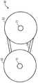
图3A 和图3B 为图2的根据一个实施方式的CVT的示意图;3A and 3B are schematic diagrams of the CVT of FIG. 2 according to one embodiment;
图4为图1的根据一个实施方式的车辆的示例性CVT的正视立体图,该CVT包括具有覆盖件和安装支架的外壳;4 is a front perspective view of an exemplary CVT of the vehicle of FIG. 1 including a housing having a cover and a mounting bracket, according to one embodiment;
图5为图4的CVT的正视立体图,其中覆盖件从安装支架移除;5 is a front perspective view of the CVT of FIG. 4 with the cover removed from the mounting bracket;
图6为图4的CVT的主离合器的侧视图;FIG. 6 is a side view of the main clutch of the CVT of FIG. 4;
图7为图4的CVT的后视立体图,其中示出了致动器组件;7 is a rear perspective view of the CVT of FIG. 4 showing the actuator assembly;
图8为图4的CVT的前视立体图,其中示出了位于打开位置的主离合器的可动槽轮;8 is a front perspective view of the CVT of FIG. 4 showing the movable sheave of the main clutch in an open position;
图9为图4的CVT的前视立体图,其中示出了位于闭合位置的主离合器的可动槽轮;9 is a front perspective view of the CVT of FIG. 4 showing the movable sheave of the main clutch in a closed position;
图10为图7的致动器组件的分解正视立体图,其中,安装支架被局部切除;Figure 10 is an exploded front perspective view of the actuator assembly of Figure 7 with the mounting bracket partially cut away;
图11为图7的致动器组件的分解后视立体图,其中,安装支架被局部切除;11 is an exploded rear perspective view of the actuator assembly of FIG. 7 with the mounting bracket partially cut away;
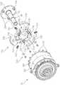
图12为图6的主离合器以及起动离合器的分解正视立体图;FIG. 12 is an exploded front perspective view of the main clutch and the starting clutch of FIG. 6;
图13为图6的主离合器以及图12的起动离合器的分解后视立体图;13 is an exploded rear perspective view of the main clutch of FIG. 6 and the launch clutch of FIG. 12;
图14为图6的主离合器的沿着图8的线14-14截取的截面图;14 is a cross-sectional view of the master clutch of FIG. 6 taken along line 14-14 of FIG. 8;
图15为图6的主离合器的沿着图9的线15-15截取的截面图;15 is a cross-sectional view of the master clutch of FIG. 6 taken along line 15-15 of FIG. 9;
图16为图14的主离合器的的立体图,其中示出了沿着图8的线14-14 截取的截面;Fig. 16 is a perspective view of the master clutch of Fig. 14 showing a cross-section taken along line 14-14 of Fig. 8;
图17为图6的被局部切除的主离合器的立体图,其中示出了可动槽轮的滑动界面;FIG. 17 is a perspective view of the main clutch of FIG. 6, partially cut away, showing the sliding interface of the movable sheave;
图18为图12的主离合器和起动离合器的局部分解正视立体图;Figure 18 is a partially exploded front perspective view of the main clutch and launch clutch of Figure 12;
图19为图12的主离合器和起动离合器的局部分解后视立体图;Figure 19 is a partially exploded rear perspective view of the main clutch and launch clutch of Figure 12;
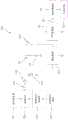
图20为根据一个实施方式的用于控制图2的CVT的示例性电动液压回路的示意图;20 is a schematic diagram of an exemplary electro-hydraulic circuit for controlling the CVT of FIG. 2, according to one embodiment;
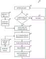
图21为示出了用于使图2的CVT的离合器移动至原位置的示例性控制策略的框图;21 is a block diagram illustrating an exemplary control strategy for moving the clutch of the CVT of FIG. 2 to a home position;
图22为图1的车辆的不具有系统电池的示例性控制系统的示意图;22 is a schematic diagram of an exemplary control system of the vehicle of FIG. 1 without a system battery;
图23为示出了图22的控制系统的用于使图2的CVT的离合器移动至原位置的示例性控制策略的框图;23 is a block diagram illustrating an exemplary control strategy of the control system of FIG. 22 for moving the clutch of the CVT of FIG. 2 to a home position;
图24为示出了用于计算图6的主离合器的目标位置的示例性方法的框图;24 is a block diagram illustrating an exemplary method for calculating the target position of the master clutch of FIG. 6;
图25为示出了用于调整在图1的车辆的所选择的传动曲线中使用的离合器控制变量的示例性输入装置;25 is a diagram illustrating an example input device for adjusting clutch control variables used in a selected transmission curve of the vehicle of FIG. 1;
图26为示出了作为从图25的输入装置输出的信号的函数的离合器控制变量的示例性曲线图;26 is an exemplary graph showing clutch control variables as a function of the signal output from the input device of FIG. 25;
图27为示出了基于节气需求的示例性目标发动机速度映射的曲线图;FIG. 27 is a graph illustrating an exemplary target engine speed map based on throttle demand;
图28为示出了用于计算目标离合器位置的作为车辆加速度的函数的示例性目标离合器速率的曲线图;28 is a graph illustrating exemplary target clutch speed as a function of vehicle acceleration for calculating target clutch position;
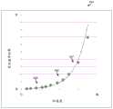
图29为示出了用于计算提供至图7的致动器组件的用于控制图6的主离合器的位置的控制信号的示例性方法的框图;29 is a block diagram illustrating an exemplary method for calculating a control signal provided to the actuator assembly of FIG. 7 for controlling the position of the master clutch of FIG. 6;
图30为示出了用于图2的马达的基于主离合器的位置的示例性外加电压限制的曲线图;30 is a graph illustrating an example applied voltage limit based on the position of the master clutch for the motor of FIG. 2;
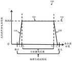
图31为示出了作为时间的函数的示例性最大可用的发动机扭矩的曲线图,用于在图2的CVT的手动操作模式下在换挡期间中断发动机的扭矩;31 is a graph showing exemplary maximum available engine torque as a function of time for interrupting engine torque during a shift in the manual operating mode of the CVT of FIG. 2;
图32为示出了用于标准的手动变速的示例性换挡方案的曲线图;FIG. 32 is a graph showing an exemplary shift scheme for a standard manual transmission;
图33为示出了用于在手动模式下操作的图2的CVT的示例性换挡方案的曲线图;33 is a graph illustrating an exemplary shift scheme for the CVT of FIG. 2 operating in a manual mode;
图34为示出了用于在车辆操作期间将图2的CVT在自动操作模式与手动操作模式之间进行转变的示例性方法的框图。34 is a block diagram illustrating an exemplary method for transitioning the CVT of FIG. 2 between an automatic mode of operation and a manual mode of operation during vehicle operation.
具体实施方式Detailed ways
贯穿多个附图,相应的附图标记指示相应的部件。本文中陈述的示例示出了本发明的实施方式,并且该示例并不意味着以任何方式限制本发明的范围。Corresponding reference characters indicate corresponding parts throughout the several views. The examples set forth herein illustrate embodiments of the invention and are not meant to limit the scope of the invention in any way.
本文中所公开的实施方式不意在是穷举的或将本公开内容限制到以下详细描述中所公开的精确形式。相反,这些实施方式被选择且描述以使得本领域的技术人员可以利用这些实施方式的教示。The embodiments disclosed herein are not intended to be exhaustive or to limit the present disclosure to the precise forms disclosed in the following detailed description. Rather, the embodiments were chosen and described so that those skilled in the art can utilize the teachings of the embodiments.
本文中使用的术语“逻辑”或“控制逻辑”可以包括在一个或多个可编程处理器上执行的软件和/或固件、专用集成电路(ASIC)、现场可编程门阵列(FPGA)、数字信号处理器(DSP)、固线逻辑、或其组合。因此,根据实施方式,各种逻辑均可以以适当的方式实施,并且将仍然属于根据本文中公开的实施方式。The terms "logic" or "control logic" as used herein may include software and/or firmware executing on one or more programmable processors, application specific integrated circuits (ASICs), field programmable gate arrays (FPGAs), digital Signal Processor (DSP), hardwired logic, or a combination thereof. Thus, various logics may be implemented in a suitable manner, depending on the embodiment, and will still belong to the embodiments disclosed herein.
首先参照图1,示出了具有电子控制CVT的示例性车辆10。示例性地,车辆10为并排式ATV(全地形车辆)10,其包括前端部12、后端部14以及通过一对前轮胎22a和前轮24a以及一对后轮胎22b和后轮24b支承在地面上方的车架或底盘15。ATV 10包括一对横向间隔开的凹背座椅18a、18b,但是可以使用椅凳式座椅或其他类型的坐椅结构。座椅18a、18b定位在ATV 10的舱室17内。保护框架16在舱室 17的上方延伸以减小ATV 10的乘客经过枝叉或树枝时受伤的可能性并在车辆翻车的情况下用作支承件。舱室17还包括前仪表板31、可调节的方向盘28以及换挡杆29。前仪表板31可以包括转速计、速度计或任意其他适当的仪器。Referring first to FIG. 1 , an exemplary vehicle 10 having an electronically controlled CVT is shown. Illustratively, the vehicle 10 is a side-by-side ATV (all-terrain vehicle) 10 that includes a front end portion 12, a
ATV 10的前端部12包括罩件32和前悬架组件26。前悬架组件26 将前轮24以枢转的方式联接至ATV 10。ATV 10的后端部14包括在发动机和变速器组件的上方延伸的发动机覆盖件19(参见图2)。后端部 14还包括将后轮24以枢转的方式联接至ATV 10的后悬架组件(未示出)。也可以设置包括本公开的CVT的其他适当的车辆,诸如雪地机动车、跨座式车辆、多用途车辆、摩托车以及其他休闲型车辆和非休闲型车辆之类。The front end 12 of the ATV 10 includes a
参照图2,示出了图1的车辆10的包括发动机42和CVT 48的示例性传动系统40。CVT48包括主离合器或传动离合器50以及副离合器或从动离合器52。环形可变速带54联接至主离合器50和副离合器 52。发动机42包括发动机壳体或外壳43以及构造成驱动CVT 48的主离合器50的输出轴44。主离合器50的旋转经由带54传递至副离合器 52。副离合器52的输出轴46联接至并驱动子变速器56,该子变速器 56联接至用于驱动车轮24的最终驱动器。在一个实施方式中,对于图 1的车辆10而言,子变速器56定档位成提供高速档、低速档、倒车档、以及停车配置。通过子变速器56可以设置更少或额外的档位。Referring to FIG. 2 , an
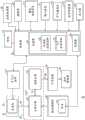
如本文中所描述的,传动系统40的控制器36操作成控制CVT 48 和发动机42。控制器36包括执行在控制器36的存储器39中的存储的软件和/或固件的至少一个处理器38。软件/固件编码包括在通过处理器 38执行时使控制器36执行本文中描述的功能的指令。控制器36可以替代性地包括一个或多个专用集成电路(ASIC)、现场可编程门阵列 (FPGA)、数字信号处理器(DSP)、固线逻辑、或其组合。控制器36 的至少一个处理器38示例性地包括操作成控制发动机42的发动机控制逻辑34以及操作成控制CVT 48的CVT控制逻辑35。控制器36可以为单个控制单元或一起起作用的多个控制单元,以执行本文中描述的控制器36的功能。发动机控制逻辑34和CVT控制逻辑35可以设置在相同的处理装置或不同的处理装置上。例如,CVT控制逻辑35可以设置在与车辆10的包括发动机控制逻辑34的发动机控制单元(ECU)物理分隔而与之通信的指定离合器控制单元上。As described herein, the
存储器39为可以通过处理器38访问的任意适当的计算机可读介质。存储器39可以为单个存储装置或多个存储装置、可以位于控制器 36的内部或外部、并且可以包括易失性介质和非易失性介质两者。示例性存储器39包括随机存取存储器(RAM)、只读存储器(ROM)、电擦除可编程ROM(EEPROM)、闪速存储器、CD-ROM、数字通用光盘 (DVD)或其他光盘存储器、磁存储装置、或构造成存储数据并可以通过控制器36访问的任意其他适当的介质。
如本文中所描述的,CVT控制逻辑35操作成控制致动器组件80,以控制主离合器50的位置并从而控制CVT 48的传动比。特别地,致动器组件80包括通过CVT控制逻辑35来控制的使主离合器50移动的马达76。在一个示例性实施方式中,马达76为电动步进马达,但是马达76也可以替代性地为有刷马达或其他适当的电动马达或液压马达。在一个实施方式中,致动器组件80和/或控制器36包括基于由CVT控制逻辑35提供的控制信号控制马达76的马达驱动器。替代性地,CVT 控制逻辑35可以控制继电器,以将动力选择性地传送至马达76以控制马达76。As described herein, the
在示出的实施方式中,节气操作件116包括联接至控制器36的位置传感器,并且发动机控制逻辑34基于节气操作件116的检测位置来电子地控制发动机42的节气门117的位置,以调控至发动机42的进气并从而调节发动机42的速度。节气操作件116可以包括加速踏板、拇指致动杆或在由操作者致动时构造成向控制器36提供操作者节气需求的任何其他适当的操作者输入装置。一个或多个悬架传感器119向控制器 36提供指示车辆悬架系统的悬架(例如压缩)高度的反馈。显示器53 联接至控制器36,以将车辆的操作信息显示给操作者。显示器53上提供的示例性信息包括车速、发动机速度、燃料液位、离合器位置或传动比、所选择的操作模式(例如自动、手动、静液压)、在手动模式下的指示档位,等。如在本文中描述的,车辆10还包括用于当车辆10在手动模拟模式下操作时在离散的传动比之间换挡的一个或多个换挡器55。速度传感器59向控制器36提供代表发动机速度、车辆(地面)速度、主离合器50和/或副离合器52的旋转速度、以及/或者车辆传动系的其他部件的速度的信号。在一个实施方式中,控制器36经由控制器区域网(CAN)通信与车辆10的一个或多个传感器/装置以及/或者其他车辆控制器通信。In the illustrated embodiment, the
操作者使用与控制器36通信的一个或多个选择装置113来选择车辆 10的操作模式。示例性操作模式包括自动模式、手动模拟模式以及静液压模式。在一个实施方式中,车辆10还包括用于选择巡航控制模式的巡航开关。此外,如本文中所描述的,输入装置111用于在自动模式下选择车辆10的驱动曲线(即,目标发动机速度曲线),以在从具有改善的燃料经济性的经济性操作至具有增大的车辆性能(例如,扭矩、加速度等)的运动操作的范围内调节车辆操作特性。如本文中所述的,在示出的实施方式中,输入装置111还用于在手动模拟模式下调节与换挡相关联的换挡强度。示例性输入装置111在图25中示出并在本文中进行描述。The operator selects the mode of operation of the vehicle 10 using one or
在示出的实施方式中,副离合器52为机械控制的离合器52,并且包括固定槽轮和可动槽轮(未示出)。副离合器52构造成在调节主离合器50时控制CVT 48的带54的张力。在一个实施方式中,副离合器52 包括弹簧和扭矩感测螺旋件(未示出)。该螺旋件在带54上施加与副离合器52上的扭矩成比例的夹持力。该弹簧施加与可动槽轮的位移成比例的载荷。在一个实施方式中,副离合器52提供了用于CVT 48的机械载荷反馈。在替代性实施方式中,控制器36和致动器组件80还可以控制CVT 48的副离合器52。In the embodiment shown, the
如图3A和图3B中所示,主离合器50联接至并轴70并与轴70一起旋转,并且副离合器52联接至轴72并与轴72一起旋转。轴70由发动机42的输出轴44驱动(参见图2)。副离合器52的轴72驱动子变速器56(参见图2)。带54缠绕主离合器50和副离合器52并将主离合器 50的旋转运动传递至副离合器52。As shown in FIGS. 3A and 3B , the
参照图4,示出了用于CVT 48的外壳60,其中,覆盖件61联接至后板或安装支架62。安装支架62和覆盖件61的凸缘部64a、64b分别示例性地构造成接纳紧固件74(参见图7)以将覆盖件61联接至安装支架62。紧固件74示例性地为螺栓或螺钉,但是也可以使用其他适当的紧固件74。覆盖件61包括形成开口69以提供至CVT 48的带54的通路的管部68。例如,开口69可以用于视觉检察带54和/或副离合器 52(参见图2)或检查带54的张力。安装支架62包括通风口结构66,该通风口结构66包括延伸到外壳60的内部中的一对通风口67a、67b(参见图5)。通风口67a、67b和开口69配合以向CVT 48提供气流,从而减小CVT 48的部件过热的可能性。通风口结构66示例性地经由紧固件75(参见图7)联接至安装支架62,但是通风口结构66可以替代性地与安装支架62或覆盖件61一体地形成。覆盖件61在将紧固件 74从凸缘部64a、64b移除后可以从安装支架62移除。如图5中所示,覆盖件61适于沿与安装支架62大致垂直的方向被推动远离安装支架 62。Referring to FIG. 4 , the
参照图5,CVT 48的主离合器50经由支架90固定至安装支架62。支架90包括凸缘部94,每个凸缘部适于接纳将支架90联接至安装支架 62的紧固件(未示出)。示例性地,支架90包括端部壁96以及在端部壁96与安装支架62之间垂直地延伸的弯曲壁98(参见图10)。在示出的实施方式中,弯曲壁98围绕主离合器50的外周局部延伸。一对柱92 进一步在端部壁96与安装支架62之间支承支架90。示例性地,柱92 压配合在端部壁96的凸缘部99与安装支架62之间,但是柱92可以替代性地通过紧固件联接至端部壁96和/或安装支架62。位置传感器114 联接至支架90的凸缘115(参见图11),以检测主离合器50的可动槽轮102的轴向位置。在一个实施方式中,位置传感器114为具有曲拐(bell crank)的旋转传感器,但是也可以设置线性传感器或其他适当的传感器。传感器114向控制器36提供位置反馈(参见图2)。Referring to FIG. 5 , the
如图5中所示,主离合器50包括由轴70支承并与轴70一起旋转的一对槽轮100、102。槽轮100、102配合以限定带54(参见图2)在其中行进的带轮或狭槽104。如图6中所示,由于相应槽轮100、102 的倾斜内表面110、112,因此狭槽104为大致V形的。因此,带64具有大致V形的截面以与槽轮100、102的内表面110、112配合。主离合器50还包括旋拧组件,该旋拧组件包括外旋拧组件120以及定位在外旋拧组件120与可动槽轮102之间的内旋拧组件122。As shown in FIG. 5 , the main clutch 50 includes a pair of
在示出的实施方式中,槽轮100沿平行于轴70的轴线的方向轴向固定,并且槽轮102可以沿平行于轴70的轴线的方向移动。特别地,槽轮102构造成沿着轴70滑动至位于完全延伸或打开位置(参见图8 和图14)与完全闭合或缩回位置(参见图9和图15)之间的多个位置。如图14中所示,在可动槽轮102位于完全延伸或打开位置中的情况下,狭槽104位于最大的轴向宽度处,并且带54在主离合器50的径向中心附近行进。在示出的实施方式中,带54在可动槽轮102位于图14的完全打开位置处时不会接触滑动支承件200的管部216。如图15中所示,在可动槽轮102位于完全缩回或闭合的位置中的情况下,狭槽104位于最小的轴向宽度处,并且带54在主离合器50的外周附近行进。副离合器52(参见图2)构造有类似地通过由轴72支承并与轴72一起旋转的一对槽轮(未示出)。副离合器52的一个槽轮可以轴向移动,并且另一槽轮轴向固定。在一个实施方式中,副离合器52构造成控制带54的张力。出于示出主离合器50的目的,在图5、图8以及图9中未示出副离合器52和带54。In the illustrated embodiment, the
主离合器50的槽轮102的运动以及副离合器52的可动槽轮的运动提供了CVT 48的可变有效传动比。在一个实施方式中,CVT 48构造成基于离合器50、52的可动槽轮的位置提供介于最小传动比与最大传动比之间的无限数目的有效传动比。在图3A中示出的构型中,主离合器50的可动槽轮102(参见图6)基本打开,并且副离合器52的可动槽轮(未示出)基本缩回。因此,在图3A的构型中通过CVT 48提供了低传动比,使得副离合器52的轴72旋转地比主离合器50的轴70慢。类似地,在图3B中示出的构型中,主离合器50的可动槽轮102(参见图6)基本缩回,并且副离合器52的可动槽轮(未示出)基本打开。因此,在图3B的构型中通过CVT 48提供了高传动比,使得副离合器52 的轴72旋转地比主离合器50的轴70快。Movement of the
如图7中所示,致动器组件80联接至安装支架62的背部。如本文中所描述的,致动器组件80构造成使主离合器50的可动槽轮102移动 (参见图5)。在示例性实施方式中,发动机42和子变速器56(参见图 2)构造成与安装支架62的背部相邻地定位在致动器组件80的任一侧部上。特别地,发动机42定位至致动器组件80的右部(如从图7中观察的),并且发动机42的输出通过安装支架62的开口82联接至主离合器50的轴70。类似地,子变速器56定位至致动器组件80的左部(如从图7观察到的),并且副离合器52(参见图3A)的轴72延伸穿过安装支架62的开口84以驱动子变速器56。As shown in FIG. 7 , the
如图10和图11中所示,致动器组件80包括具有带齿轮的输出轴 132的马达76、容置在齿轮外壳78内的减速齿轮130、以及从安装支架 62的前部向外延伸的主齿轮驱动器86。减速齿轮130包括联接至轴135 的第一齿轮134和第二齿轮136。第一齿轮134与马达76的带齿轮的输出轴132接合,并且第二齿轮136与联接至主齿轮驱动器86的轴109 的端部的第一齿轮106接合。主齿轮驱动器86还包括联接至轴109的与第一齿轮106相对的端部的第二齿轮108。第二齿轮108与主离合器 50的旋拧组件120(参见图6)的外齿轮126接合。As shown in FIGS. 10 and 11 , the
齿轮外壳78包括凸缘部156,每个凸缘部156均构造成接纳将齿轮外壳78联接至安装支架62的后部的紧固件158(参见图7)。齿轮外壳 78包括第一部分150、第二或中间部分152以及第三部分154。第一部分150包括接纳马达76的输出轴132的开口151(参见图11)。第二部分152包括接纳减速齿轮130的开口153(参见图10)。减速齿轮130 在一个端部上由第二部分152支承,并且在另一端部上由安装在安装支架62的前部面上的支承构件140支承。轴承142、146分别定位在轴135 的相对的端部处以有助于减速齿轮130在第二部分152和支承构件140 内的旋转。外壳78的第三部分154容置第一齿轮106的一部分并支承轴109的与第一齿轮106相邻的端部。类似地,支架90的端部壁96支承轴109的与第二齿轮108相邻的另一端部。如图11中所示,轴承144、 148联接在轴109的相对的端部处,以有助于主齿轮驱动器86相对于齿轮外壳78和支架90的旋转。特别地,轴承148接纳在齿轮外壳78的第三部分154内,并且轴承144接纳在支架90的端部壁96中形成的开口95内。The
参照图12至图16,主离合器50的外旋拧组件120包括颈部128和带螺纹的旋拧部127。颈部128延伸穿过形成在支架90的端部壁96中的开口97(参见图10)。外轴承支承件184经由支承组件183旋转地联接至颈部128以及固定地联接至轴70的端部71。以此,轴70和外轴承支承件184与外旋拧组件120独立地但一起旋转。在示出的实施方式中,轴70的端部71压配合到外轴承支承件184中。端部71还包括与外轴承支承件184的内脊状部189接合的周向沟槽73(参见图14)。轴70 的端部71也可以通过粘合剂或其他适当的紧固件紧固至外轴承支承件 184。Referring to FIGS. 12-16 , the
内旋拧组件122包括板部186以及从板部186径向向内定位的带螺纹的旋拧部188。示例性地,L形壁185联接在板部186与旋拧部188 之间,从而在旋拧部188与壁185之间形成了径向间隙187。旋拧部188 包括与外旋拧组件120的旋拧部127的内螺纹129配合的外螺纹196。外旋拧组件120的旋拧部127接纳在形成在内旋拧组件122(参见图14 至图16)中的间隙187内。径向定位在壁185的内侧的O环密封件192 构造成抵靠外旋拧组件120的旋拧部127。内旋拧组件122的板部186 包括具有以可滑动的方式接纳支架90(参见图8和图9)的柱92的孔口125(参见图12和图13)的凸缘124。板部186还包括在板部186 的外径附近沿周向间隔开的狭槽194。The
仍然参照图12至图16,主离合器50的滑动组件包括轴衬组件172、滑动支承件200以及定位在轴衬组件172与内旋拧组件122之间的轴承组件190。主离合器50的轴衬组件172包括接纳从中贯穿的轴70的颈部176以及联接至可动槽轮102的沿周向间隔开的坐置件202的多个凸缘174。多个紧固件173——示例性地为螺钉173——通过凸缘174和坐置件202的相应的孔口接纳,以将轴衬组件172联接至槽轮102。定位在颈部176内的轴衬178接合轴70并支承可动槽轮102的外端部。轴 70构造成在发动机空转时(当主离合器50分离时)在轴衬178的内侧旋转以及当主离合器50被接合时与轴衬178一起旋转。轴衬178构造成提供在槽轮102的运动期间沿着轴70滑动的低摩擦表面。轴衬178 可以替代性地为滚针轴承。Still referring to FIGS. 12-16 , the slip assembly of the main clutch 50 includes a
轴衬组件172的颈部176经由定位在旋拧部188内的轴承组件190 旋转地联接至内旋拧组件122的旋拧部188。衬环182和带齿锁定垫圈 180联接至延伸通过旋拧部188的颈部176(参见图14至图16)。锁定垫圈180示例性地包括与颈部176的外表面中的相应狭槽177(参见图 12)接合的内突部181(参见图12),使得锁定垫圈180与轴衬组件172 一起旋转。衬环182螺纹连接到颈部176上并且通过带突部的锁定垫圈 180在颈部176上可旋转地安装就位。因此,轴衬组件172、槽轮100、槽轮102、衬环182、垫圈180以及外轴承支承件184构造成与轴70一起旋转,而外旋拧组件120和内旋拧组件不与轴70一起旋转。轴衬组件172构造成经由轴承178沿着轴70轴向滑动。The
滑动支承件200联接至槽轮100、102,以提供用于可动槽轮102相对于固定槽轮100的滑动界面。如图14至16中所示,滑动支承件200 包括管部216以及联接至该管部216并与该管部216大致垂直的板部 214。在一个实施方式中,板部214和管部216模制在一起,但是板部 214和管部216也可以通过紧固件或其他适当的联接装置联接在一起。板部214和管部216各自与槽轮100、102和轴70一起旋转。一对密封件220a、220b以及定位在密封件220a与密封件220b之间的离合器218 均联接在管部216与轴70之间。离合器218示例性地为在车辆空转期间靠惯性滑行并且在发动机制动期间将管部216锁定至轴70的单向离合器218。以此,单向离合器218在空转条件期间用作管部216与轴70 之间的轴承,并且当CVT 48被驱动地比发动机42更快时(即,当带 54和离合器50使得过度驱动图2的发动机42时)将管部216锁定至轴 70。A sliding
如图12中所示,板部214包括围绕板部214的外径沿周向间隔开的多个滑动联接件206。在示出的实施方式中,板部214的外径与可动槽轮102的外径基本相同,使得板部214的联接件206与槽轮102的内圆筒形壁203紧密相邻。联接件206示例性地的夹子206,夹子206构造成以滑动的方式接纳围绕可动槽轮102的内壁203沿周向间隔开的相应的滑动构件或脊状部204。脊状部204从圆筒形内壁203径向向内延伸并且大致垂直于圆筒形内壁203。脊状部204示例性地包括径向宽度以及基本上大于该径向宽度的径向高度。如图17中所示,低摩擦衬垫 208定位在每个夹子206中以与脊状部204的滑动表面接合。在一个实施方式中,衬垫208为低摩擦复合材料或塑料材料的,诸如例如具有添加剂以减小摩擦的聚醚醚酮(PEEK)、聚酰亚胺基塑料(例如聚酰亚胺) 或尼龙。如图14至图16中所示,圆筒形轴承或轴衬222和O形环密封件224定位在可动槽轮102与管部216之间,以将槽轮102径向定位在管部216上。轴衬222提供了用于槽轮102的相对于管部216的低摩擦滑动表面。在一个实施方式中,油脂设置在脊状部204与夹子206之间以及轴衬222与管部216之间的界面中以减小滑动摩擦。As shown in FIG. 12 , the
可动槽轮102构造成沿着图12的脊状部204相对于滑动支承件200 滑动。在一个实施方式中,通过使联接件206与脊状部204之间的滑动界面位于可动槽轮102的外径附近而使槽轮102与滑动支承件200之间的滑动摩擦最小化。在示出的实施方式中,可动槽轮102的外径相对于轴70和管部216的外径较大。在一个实施方式中,可动槽轮102的外径是轴70和管部216的外径的至少三倍大。The
如图14至图16中所示,轴承组件183和190各自均定位在可动槽轮102的外轮廓的外侧。特别地,参照图14,轴承组件183、190轴向地定位在槽轮102的位于平面198中的端部的外侧。以此,轴承组件183、 190与通过联接件206和脊状部204以及通过轴衬222和管部216形成的滑动界面轴向地间隔开。在一个实施方式中,轴承组件183、190包括角接触轴承,但是也可以使用其他适当的轴承。如图14中所示,轴衬组件172的颈部176还示例性地定位在可动槽轮102的外轮廓的外侧。As shown in FIGS. 14-16 , bearing
在操作中,齿轮传动器86由马达76(参见图10)致动,该致动构造成调整由主离合器50设置的传动比。参照图10,马达76的输出通过减速齿轮130传递至主齿轮驱动器86,以从而旋转主离合器50的外旋拧组件120(参见图8)。外旋拧组件120轴向固定并且独立于轴70的旋转由于主齿轮驱动器86的旋转而旋转。参照图8和图14,外旋拧组件120在第一方向上的旋转将内旋拧组件122的带螺纹的旋拧部188从外旋拧组件120的带螺纹的旋拧部127拧开,从而使得内旋拧组件120 在保持旋转固定的同时沿着柱92朝向固定槽轮100轴向滑动。In operation, the
参照图14,内旋拧组件122的轴向移动经由轴衬组件172提供了抵着可动槽轮102的推力,以使槽轮102朝向固定槽轮100移动。如本文中所描述的,轴衬组件172经由轴承组件190在旋转地固定的内旋拧组件122内旋转。以此,由内旋拧组件122提供的推力通过轴承组件190 施加至轴衬组件172。类似地,外旋拧组件120在相反的第二方向上的旋转使得内旋拧组件122沿着柱92(参见图8)远离固定槽轮100轴向移动,并且通过轴承组件190在轴衬组件172和可动槽轮102上施加推力。轴承组件183、190提供了内旋拧组件122、轴衬组件172以及槽轮 102相对于轴70的轴向运动,该轴向运动独立于轴70、槽轮100和102、滑动支承件200以及轴承组件172的旋转运动。在示出的实施方式中,内旋拧组件122相对于外旋拧组件120的轴向运动的范围限定了由主离合器50设置的最大传动比和最小传动比,但是也可以设置其他限制止动件。Referring to FIG. 14 , axial movement of the
如图18和图19中所示,离合器组件170联接至轴70以用作用于离合器50的发动或起动离合器。离合器组件170示例性地为整合到主离合器50中的干式离心离合器170。离合器组件170构造成定位在发动机42的发动机壳体43(参见图2)的外部。以此,离合器组件170与发动机42的发动机壳体43不为一体,并且因此不位于发动机油中。相反,离合器组件170定位在发动机壳体43的外侧并联接至发动机42的输出轴44,以操作为用于主离合器50的干式起动离合器。以此,离合器组件170通过从轴44拉动离合器组件170而能够从发动机42移除。As shown in FIGS. 18 and 19 ,
在组装中,离合器组件170定位在主离合器50的内部209中(参见图19)。离合器组件170包括联接至轴70并具有多个桩件234的端部板232。在示出的实施方式中,轴70和端部板232一体地形成,但是轴 70也可以利用紧固件或压配合构型联接至端部板232。如图14中所示,轴70包括分别为大致圆筒形的外表面226和大致圆筒形的内表面228。内表面228形成了轴70的中空内部区域229。示例性地,外表面226 和内表面228从端部板232朝向端部71逐渐变小。轴70的外表面还包括阶梯部88,使得轴70的由轴衬组件172和外轴承支承件184接纳的部分的直径小于轴70的定位在滑动支承件200的管部216中的部分的直径。在示出的实施方式中,发动机42(参见图2)的输出轴44由轴 70的内部区域229接纳以驱动离合器组件170的旋转。以此,离合器组件170和轴70与发动机42一起旋转。In assembly, the
参照图18和图19,离合器组件170还包括经由紧固件240以枢轴的方式安装至桩件234的鞋状部或臂238。臂238各自包括接纳端部板 232的相应的桩件234的孔口236。紧固件240示例性地包括螺栓和垫圈。每个臂238包括联接至每个臂238的外周表面的摩擦垫230。弹簧 242在坐置件244处联接在相邻臂238之间以使臂238偏置成相对于彼此隔开。Referring to FIGS. 18 and 19 ,
在示出的实施方式中,离合器组件170在发动机42(参见图2)处于发动机空转速度或低于发动机空转速度时与主离合器50分离。随着发动机速度以及离合器组件170的相应的旋转速度增大,作用在臂238 上的离心力克服弹簧242的偏置力,并且使得臂238的端部246径向向外摆动,从而迫使摩擦垫230与固定槽轮100的内摩擦表面210(参见图13)接合。离合器组件170与固定槽轮100的接合将扭矩传递至滑动支承件200和可动槽轮102。以此,槽轮100、槽轮102、滑动支承件 200以及轴衬组件172都与轴70一起旋转。当轴70的旋转速度减小至阈值速度时,减小的离心力使得臂238远离槽轮100的表面210径向向内移动。以此,离合器组件170与主离合器50分离。固定槽轮100示例性地包括沿周向间隔开的多个冷却翅片212,多个冷却翅片212构造成减小由离合器组件170的接合所产生的热量。In the illustrated embodiment, the
在示出的实施方式中,在从安装支架62移除覆盖件61和支架90 时(参见图5),分离的离心起动离合器170允许主离合器50作为一个组装单元被拉动离开轴70。带54(参见图2)可以在从轴70移除主离合器50后被移除和/或更换。此外,致动器组件80(参见图9和图10) 在主离合器50从轴70移除时保持联接至安装支架62,使得致动器组件 80的齿轮(例如,减速齿轮130)不需要被移除以及重置或重新校准。在一个实施方式中,主离合器50和带54可以在不移除主齿轮驱动器86 (参见图5)的情况下从轴70移除。In the embodiment shown, the disengaged
离心起动离合器170用于将主离合器50的换挡功能与主离合器50 的接合功能分离。特别地,换挡功能经由控制器36(参见图2)的CVT 控制逻辑35通过主离合器50来执行,而主离合器50的接合通过起动离合器170来控制。以此,控制器36不需要控制主离合器50的接合,这是因为在达到预定的旋转速度时起动离合器170自动接合主离合器 50。The
在替代性实施方式中,主离合器50可以构造成在没有起动离合器 170的情况下操作。例如,在该实施方式中,CVT 48的主离合器50直接联接至发动机42的输出。如图6中所示,当车辆10处于空转或没有行进时,CVT控制逻辑35将可动槽轮102定位成远离固定槽轮100,使得带54朝向轴70径向向内定位。在一个实施方式中,CVT控制逻辑35在发动机42空转或没有运行时将槽轮102定位在最大打开位置处,使得可动槽轮102不会接触带54。在一个实施方式中,槽轮102在子变速器56(参见图2)的换挡期间与带54分离。以此,副离合器52在使子变速器56换挡时以零速度或最小速度旋转。在请求发动机驱动扭矩时——例如在由操作者提出节气请求时——开始槽轮102与带54的接合。在另一实施方式中,槽轮102在子变速器56换挡离开空挡并进入挡位之后移动成与带54接合。在另一实施方式中,可动槽轮102在发动机空转期间被弹簧加载而远离带54,并且子变速器56的换挡机械地引起槽轮102向回移动成与带54接合。In alternative embodiments, the main clutch 50 may be configured to operate without the
在一个实施方式中,图2的CVT控制逻辑35在检测到车辆10处于升空时通过使CVT48自动换挡(即,调节主离合器50)而提供了用于传动系的尖峰载荷减小的功能。例如,当图1的车辆10处于升空时,车轮24由于车轮24失去与地面的接触而可以迅速加速,而同时节气操作件116(参见图2)仍然与操作器接合。当车轮24在车辆10着陆时再次接触地面时,轮速可能会突然减速,从而可能导致损坏CVT 48的部件以及其他传动系部件或向CVT 48的部件以及其他传动系部件施压。CVT控制逻辑35在检测到车辆10处于升空时起动尖峰载荷控制,以减小升空车辆10的传动系加速度(例如,最终驱动器58的加速度)。在一个实施方式中,CVT控制逻辑35在尖峰载荷控制期间减小CVT 48 调高档速的速率。在一个实施方式中,CVT控制逻辑35在尖峰载荷控制期间至少暂时停止CVT48调高档速或使CVT 48调低档速至更小的传动比。以此,车辆10的传动系加速在车辆10返回至地面之间被减慢,并且在车辆10着陆时使在CVT 48和其他传动系部件(例如,子变速器56、最终的驱动器58等)上的惯性加载减小或最小化。In one embodiment, the
在一个实施方式中,CVT控制逻辑35自动调节升空车辆10的CVT 48的传动比,使得轮速被控制成接近在车辆10刚刚变为升空之前所检测到的轮速。例如,CVT控制逻辑35在车辆10刚刚变为升空之前或在车辆10从接地状态转变至升空状态期间确定车辆10的轮速。所确定的轮速设定为目标速度,并且CVT控制逻辑35在检测到升空状态后调节CVT 48,以控制轮速朝向目标速度返回。在一个实施方式中,CVT 控制逻辑35调节CVT 48,直到轮速到达目标速度为止或直到车辆10 返回至地面为止。以此,在一个实施方式中,CVT控制逻辑35调节CVT 48,使得在车辆10返回至地面时车辆10的轮速与在车辆10刚刚变为升空之前所检测到的轮速基本相同。In one embodiment, the
在一个实施方式中,控制器36在检测到传动系部件中的突然加速时确定车辆10为升空。例如,控制器36可以基于来自轮速传感器、发动机速度传感器、变速器速度传感器或位于车辆10的传动系上的其他适当的速度传感器来检测突然加速。在示出的实施方式中,控制器36 通过用速度传感器59测量CVT 48或子变速器56的轴中的一个轴的速度来持续监测传动系的角加速度。在轮速或传动系速度的加速度超出车辆10的设计规格时,确定车辆10升空。例如,车辆10基于来自发动机42的可用扭矩、来自地面的摩擦力、车辆10的重量以及其他设计限制而具有最大的车轮加速度。当所监测的传动系部件以比车辆10处于正常操作条件下(即,当车轮24与地面接触时)能够实现的更快的速率加速时,控制器36确定车轮24已经与地面失去接触。一个或多个预定的加速度限制存储在存储器39(图2)中,该加速度限制与车辆10 的设计限制对应以触发尖峰载荷控制。在车辆10返回至地面时,控制器36检测车辆10的接地状态,并且恢复CVT 48的正常控制。在一个实施方式中,控制器36基于车辆悬架的所检测的压缩度来检测接地状态。In one embodiment, the
在一个实施方式中,CVT控制逻辑35的尖峰载荷减小特征与电子节气控制系统(例如,发动机控制逻辑34)共同作用,以在检测到升空条件时减小传动系的加速度(即,通过减小节气开度等),如在2011年 6月3日提交的名称为“Electronic Throttle Control(电子节气控制)”的美国专利申请No.13/153,037中所描述的,其全部内容通过参引并入本文。在车辆10为升空时,CVT 48控制和电子节气控制一起用于减小传动系的加速度。在某些操作条件下,在车辆10为升空时通过节气操作件116来提供高的或增大的节气需求。在一个实施方式中,发动机42 由于高的节气需求而持续旋转加速,直到达到发动机42的旋转加速限制为止。在具有电子节气控制的示例性车辆10中,在检测到升空条件时自动限制到达发动机42的气流,以减小发动机功率并减小达到旋转加速限制的可能性。In one embodiment, the peak load reduction feature of the
如参引的美国专利申请No.13/153,037中所描述的,控制器36可以利用其他方法——诸如通过用悬架高度传感器来检测车辆10的悬架系统(例如,图1的前悬架组件26和/或后悬架)的压缩距离或高度以及/或者通过监测发动机扭矩和动力——来检测车辆10的升空条件。例如,车辆10包括构造成测量车辆悬架的高度或纵向压缩度(例如,冲击)的一个或多个悬架传感器119(参见图2)。在车辆10定位在地面上的情况下,车辆10的重量使得悬架压缩至第一高度。在轮胎22a和/ 或轮胎22b(参见图1)升空的情况下,车辆10的重量从悬架系统移除,并且悬架解除压缩或延伸至第二未加载高度。基于来自传感器119(参见图2)的反馈,控制器36在悬架延伸穿过第一高度或延伸至第二未加载高度时确定车辆10为升空。在一个实施方式中,在控制器36确定车辆10为升空之前悬架必须延伸一阈值时间量。在一个实施方式中,控制器36一起使用所检测出的冲击高度和所检测出的轮速加速度来确定车辆10为升空。As described in referenced U.S. Patent Application No. 13/153,037, the
在一个实施方式中,CVT 48还包括行星齿轮组件以提供无级变速器系统。在一个实施方式中,行星齿轮组件由齿圈、联接至承载件的若干行星齿轮以及恒星齿轮构成。齿圈经由齿轮或链条由发动机42的输出直接驱动。行星齿轮和承载件联接至副离合器52并由该副离合器52 驱动。恒星齿轮用作CVT 48的输出并连接至子变速器56。基于行星齿轮组件的传动比,组合的CVT 48和行星齿轮组件构造成通过改变CVT 48的传动比而提供正速度和负速度(向前和向后)。在一个实施方式中,通过控制器36设置的并且在本文中描述的静液压模式在具有行星齿轮组件的CVT 48中实施。In one embodiment, the
在一个实施方式中,如通过图20的示例性电液压回路278所示, CVT 48为电液压致动的。在图20的示出的实施方式中,CVT 48的主离合器50由电液压回路278而非由图10和图11的致动器组件80来致动。回路278还可以构造成控制副离合器52。电液压回路278示例性地包括液压回路282和电回路284。控制器36示例性地接收模拟输入250、数字输入252以及CAN输入254。示例性模拟输入250和数字输入252 包括液压系统压力传感器、离合器位置传感器(例如,图20的传感器 290)、伺服阀位置传感器以及检测车辆10的各种参数的其他传感器。示例性CAN输入254包括发动机速度传感器、节气位置传感器、车速传感器、车辆操作模式传感器以及检测车辆10的各种参数的基于CAN 的其他传感器。控制器36构造成基于输入250、252、254控制电回路 284的电动马达262以及液压回路282的泵264和伺服阀272。In one embodiment, the
马达驱动器256构造成基于来自控制器36的控制信号来控制提供至马达262的功率。替代性地,继电器可以设置在马达驱动器256的适当位置中,该继电器由控制器36选择性致动以向马达262提供固定的功率。马达262可以为适于驱动泵264的任意马达类型。在示出的实施方式中,马达262为直流(DC)电动马达。电压供给261——示例性地为12VDC——设置至马达262,并且马达262的速度经由马达驱动器 256而由控制器36来控制。马达262的输出263驱动泵264。在示出的实施方式中,泵264为可变排量泵264。控制器36的泵控制单元258 基于输入250、252、254来调整泵264的排量以控制液压回路282的液压。泵264可以替代性地为固定排量泵。
液压调节器268存储加压的液压流体以在满足液压回路282的压力需求的情况下辅助泵264和马达262。例如,蓄力器268构造成在CVT 48的峰值换挡速率期间实现液压回路282所需的压力需求。以此,在 CVT 48的峰值换挡速率期间在电回路284上引发尖峰载荷的可能性降低。卸压阀270设置成将液压管路288上的压力维持在预定的最大阈值压力以下。卸压阀270、泵264以及伺服阀272联接至液压返回储蓄室 280。
伺服阀272调控液压流体从管路288至致动器274的流动以调节可动槽轮102的位置。伺服阀272示例性地为通过控制器36的伺服阀控制器260控制的三相电液压伺服阀272。控制器36的伺服阀驱动器 260基于输入250、252、254来控制伺服阀272。致动器274——示例性地为线性液压致动器——包括经由旋转轴承276联接至可动槽轮102的活塞275。在一个实施方式中,旋转轴承276为凸缘轴承或面轴承,但是也可以设置其他适当的轴承276。在一个实施方式中,致动器274联接至车辆10(参见图1)的底盘15,并且可动槽轮102围绕致动器274 的活塞275旋转并且经由轴承276相对于致动器274轴向移动。伺服阀 272经由液压管路286联接至致动器274。在一个实施方式中,管路286 为小直径高压力的液压管路286。通过用伺服阀272调控流体至致动器 274的流动,致动器274的线性位移被调节成引起可动槽轮102的相应的轴向调节。
在一个实施方式中,电回路284和液压回路282远离CVT 48定位在车辆10(参见图1)上,并且致动器274定位成与CVT 48的外壳 60(参见图4)紧相邻或定位在CVT 48的外壳60内。以此,液压管路 286从伺服阀272行进至定位在CVT 48附近的致动器274。例如,电回路284和液压回路282可以设置在罩32和/或座椅18a、18b(参见图 1)的下方,并且CVT 48和致动器274可以朝向车辆10的后端部14 定位在发动机覆盖件19(参见图1)的下方。以此,CVT 48的可动槽轮102的致动部件(即致动器274)在CVT 48的位置处占据了较小的空间,而电液压回路278的其余部件中的某些部件或所有部件均定位在车辆10的其他位置处。In one embodiment, the
在一个实施方式中,经由致动器274施加至可动槽轮102的压力被调整成以实现CVT 48的期望传动比以及/或者传动带54上的期望收紧力。如图20中所示,位置传感器290构造成检测可动槽轮102的线性位置并通过检测的位置数据向控制器36提供相应的信号。以此,槽轮102的位置在操作期间可以被监测。在一个实施方式中,控制器36 在可动槽轮102的控制中实现了故障-安全模式。特别地,如本文中所描述的,当由控制器36检测到系统故障或信号损失时,可动槽轮102 定位成最大的低比率或打开位置,使得带54上的收紧力最小化或被移除。示例性系统故障为当输入250、252检测到液压回路282中没有液压或液压不充分时。In one embodiment, the pressure applied to the
再次参照图2的传动系统40,CVT 48的电控制离合器50、52构造成在车辆10停车之前或在车辆10停车时移动至原位置。例如,控制离合器50、52移动至其完全打开位置(例如参见图8)或移动至其完全闭合位置(例如参见图9)。在示出的实施方式中,如图8中所示,在车辆停车时,主离合器50的可动槽轮102移动至其最远的打开位置。以此,可动槽轮102定位成在车辆10起动之前远离带54并与带54脱离接触,从而减小在发动机42启动时车辆10加速的可能性。在一个实施方式中,对于电控制的副离合器52而言,副离合器52的可动槽轮(未示出)在车辆停车时或停车之前移动至其最远的闭合位置。Referring again to the
参照图2,车辆10包括系统电池118(例如12VDC),该系统电池118构造成提供用于起动车辆10的动力并构造成在操作期间向车辆10提供周界动力。系统电池118向致动器组件80提供动力,以在车辆 10停止或停车并换挡至空档时使可动槽轮102移动至原位置。如在本文中参照图21至图23所描述的,CVT 48的主离合器50还构造成在车辆 10遭受突然的动力损失时返回至原位置。Referring to FIG. 2 , the vehicle 10 includes a system battery 118 (eg, 12 VDC) configured to provide power for starting the vehicle 10 and to provide perimeter power to the vehicle 10 during operation. The
在另一实施方式中,车辆10不具有系统电池118。例如,车辆10 可以包括通过操作者拉动以起动发动机42的机械绳组件或机械回弹组件。特别地,由操作者拉动绳使起动车辆10的发动起42的动力发生器旋转,并且在操作期间,动力发生器在被驱动时通过使发动机42旋转而向车辆10的电子部件提供外围动力。例如参见图22的发生器304。以此,在车辆10停车时,来自系统电池118的动力不能用于使主离合器50移动至其原位置。如本文中所描述的,在该实施方式中,主离合器50在车辆10停车之前利用发生器304提供的动力移动至其原位置。In another embodiment, the vehicle 10 does not have the
参照图21,示出了用于在不具有系统电池118的车辆10中使主离合器50移动至其原位置的示例性控制策略350。控制策略350示例性地通过图2的控制器36来实施。在框352处,在车钥匙移动至开(ON) 位置时在车辆10上提供指示器(例如可听或可视)以向操作者指示主离合器50是否位于其原位置。在一个实施方式中,指示器——诸如灯之类——例如由小的低电压电池供以动力。指示器可以替代性地机械连接至CVT 48以检测离合器50的位置。如在框354、356和358处所示,如果主离合器50位于其原位置处,则通过操作者起动发动机42。例如,操作者可以经由手动起动系统——诸如绳/回弹组件或脚踏起动组件之类——起动发动机42。在一个实施方式中,在主离合器没有位于其原位置处时手动起动系统的致动在框352处被阻止。Referring to FIG. 21 , an
当在框360处操作者要求发动机42停止(即将车钥匙转动至关 (OFF))时,在控制器36允许发动机42切断动力之前主离合器50在框362处自动返回至其原位置。特别地,控制器36在框362执行停车步骤,其中,尽管操作者要求停车,但是控制器36保持发动机动力,通过将动力从发生器304(图22)传送至致动器组件80而使主离合器 50的槽轮102移动至其原位置,并且随后允许发动机42停机(框364)。在框366处,发动机42停机。因此,主离合器50在发动机42停机之前位于其原位置处,使得车辆10可以在将来的某一时间再次适当地起动而不需要重置离合器50。When the operator requests the
在框352处如果主离合器50没有位于其原位置,则如框368、370 以及372处所示,主离合器50必须在起动车辆10之间移动至其原位置。例如,在控制器36能够将离合器50重置至其原位置之前,离合器50 在车辆10突然损失动力时需要重置。主离合器50可以手动或经由自动控制重置。在框374处的手动重置中,操作者移除CVT 48的覆盖件61 (参见图5)并通过转动外旋拧组件120(参见图5)而将可动槽轮102 手动重置其原位置。如图22的示例性控制系统300中所示,在框376 的自动重置中,车辆10包括用于将车辆10连接至外动力供给322(例如12VDC)的辅助动力连接件330。在一个实施方式中,如图22中所示,通过辅助动力连接件330供给的外部动力被传送至控制器36以向控制器36供以动力。在检测到外部动力的存在时,控制器36经由致动器组件80将主离合器50移动至其原位置。在另一实施方式中,通过辅助动力连接件330提供的动力被传送至开关324或由操作者致动以使主离合器50返回至原位置的其他工具(例如故障诊断工具)。例如,开关 324包括允许电流经过而到达致动器80以使离合器50移动至原位置的闭合位置以及阻塞来自致动器80的电流的断开位置。操作者致动开关 324以控制至动力到致动器80的传递并从而控制离合器50的位置。在一个实施方式中,开关324与控制器36(如图22中所示)一起使用,使得开关324能够实现或不能实现通过控制器36控制离合器50以使其自动返回至原位置。替代性地,开关324可以绕开控制器36,使得开关 324在没有控制器36的情况下控制动力至致动器80的传递以及离合器50的位置。在框378处,如果主离合器50位于原位置处,则操作者能够在框354和356处起动发动机42。在框378处如果主离合器50没有位于原位置处,则该过程返回至框372以用于离合器50的额外手动或自动运动。If the
参照图22,示例性控制系统300还构造成提供用于在不具有系统电池118(图2)的情况下在车辆10中发生突然动力损失时使离合器返回至原位置的故障安全。控制系统300示例性地包括微控制器302,该微控制器控制开关320以将存储在电容器316处的动力选择性地传送至控制器36。微控制器302包括处理器以及能够被该处理器访问的存储器,该存储器包含具有用于监测车辆动力306、检测动力中断、以及控制开关320的指令的软件。微控制器302和控制器36可以替代性地整合为单个控制器,该单个控制器包括执行两个控制器302、306的本文中所描述的功能的逻辑。在车辆操作期间由发动机42(图2)驱动的发生器304提供了用于控制器36、微处理器306以及其他车辆部件的车辆动力306(示例性地为12VDC),并且在车辆操作期间用于对电容器316 进行充电。电容器316可以替代性地经由辅助连接330通过外动力供给 322来充电。电容器316在与致动器80电脱离的同时(即,在开关320 打开的情况下)在车辆操作期间进行充电。保险丝308和二极管310——示例性地为稳压二极管310——串联地设置在车辆306与控制器302、 36之间以提供反向电压保护。二极管312——示例性地为瞬态电压抑制二极管312——联接在二极管310的输出与地面之间以对控制器302、 36提供过电压保护。电阻器314设置用于对电容器316充电。Referring to FIG. 22 , the
微控制器302构造成在检测到车辆动力306的动力损失时闭合开关320。例如,在车辆10突然损失动力并且发生器304停机时,微控制器302感测车辆动力306的下降或损失并闭合开关320。在一个实施方式中,微控制器302包括在车辆动力损失之后向微控制器302供以动力使得微控制器302可以在动力损失之后闭合开关320的动力源(例如电容器)。在开关320闭合的情况下,存储在电容器316处的动力被传送至控制器36,以使CVT 48的主离合器50移动至原位置。在一个实施方式中,电容器316为超级电容器。电容器316可以包括另一适当的能量存储装置316,诸如锂离子电池或小于典型的车辆系统电池318(图2) 的其他轻量级电池。The
参照图23,示出了用于图22的控制系统300的示例性控制策略 400。在框402处的发动机运行的情况下,在框404处操作者发出车辆停机的信号,并且在框406处执行用于车辆10的正常停机过程。例如,在图21的框360、362、364和366中示出的并且在本文中进行描述的停机过程在图23的框406处执行。如果在框410处由控制器302(图 22)检测到突然的动力损失,则控制器302在框412处判断电容器316 是否充电且正常工作。如通过图21的框374和376所描述的,如果控制器302确定电容器316没有正常工作,则开关320没有闭合并且在框418处主离合器50手动地或经由辅助动力连接件320移动至其原位置。在框412处如果电容器316正常工作,则在框414处微控制器302闭合开关320以将动力从电容器316传送至控制器36。控制器36使用来自电容器316的动力来驱动致动器组件80以使CVT 48的主离合器50移动至其原位置。在框416处,控制器36(或微控制器302)基于来自位置传感器(例如,图20的传感器290)的反馈来判断离合器50是否处于其原位置。如果离合器50处于其原位置,则在框408处确定车辆10 的停机是适当的。如果在框416处离合器50没有处于其原位置,则过程400进行至用于离合器50的手动(或自动)重置的框418,如在本文中通过图21的框374、376描述的。在一个实施方式中,电容器316基于初始操作条件的预定最坏情况设定(此情况设定下可能发生动力中断)而定尺寸成包括用于使离合器50移动至其原位置的足够能量。Referring to Figure 23, an
在另一实施方式中,车辆10包括用于在系统动力被移除时使主离合器50自动定位在原位置处的机械返回系统。例如,在该实施方式中,机械弹簧/连杆系统联接至主离合器50的可动槽轮102(参见图5),以在车辆10断掉动力时将主离合器50定位在其原位置中。如本文中所描述的,当动力回归至车辆10时,控制器36正常操作以控制主离合器50。In another embodiment, the vehicle 10 includes a mechanical return system for automatically positioning the
CVT控制逻辑35(图2)操作成在检测到轮胎牵引力损失时实施牵引力控制。特别地,控制器36在检测到一个或多个车轮24(图1) 的高速度改变速率时——即当速度改变速率超出阈值速率时——确定牵引力损失。例如,一个或多个车轮24在牵引力损失时可以迅速加速或降速,从而指示车轮24已经打滑失控或已经被锁定。在一个实施方式中,在检测到牵引力损失时,CVT控制逻辑35抑制CVT 48的换挡并将CVT 48的传动比保持为大致恒定,直到确定已经重新获得牵引力为止。通过使传动比保持为恒定,由于车轮24的速度在牵引力损失期间的快速改变而避免了CVT 48的不期望的换挡。在一个实施方式中, CVT控制逻辑35基于所监测的车轮24速度确定已经重新获得牵引力。The CVT control logic 35 (FIG. 2) operates to implement traction control when a loss of tire traction is detected. In particular, the
控制器36提供了用于CVT 48的能够通过一个或多个选择装置 113(图2)来选择的多种操作模式。示例性操作模式包括自动、手动模拟以及静液压模式。此外,控制器36提供了能够通过巡航开关选择的巡航控制模式。在巡航控制模式中,发动机节气位置以及CVT48的传动比中的至少一者保持为恒定,以将车速保持在目标车速处。在一个实施方式中,操作者选择巡航控制模式后的车速设定为目标车速,但是可以由操作者经由车辆10的用户界面输入目标车速。在一个实施方式中,在巡航模式下发动机42的节气位置通过发动机控制逻辑34被锁定或保持恒定,以将发动机扭矩保持为大致恒定,并且CVT 48的传动比基于车速反馈通过CVT控制逻辑35而变化以保持目标车速。在另一实施方式中,在巡航控制期间CVT 48的传动比保持为恒定,同时发动机42 的节气位置改变以保持目标车速。替代性地,节气位置以及CVT 48的传动比两者均可以被保持为大致恒定或可以被同时调节以将车速控制至目标速度。
在静液压模式下,发动机速度以及CVT 48的传动比由操作者独立控制。例如,发动机速度基于车辆10的特定使用或应用——即,用于通过动力输出装置实现向车辆供以动力、用于对系统电容器进行充电等——来进行选择(例如通过节气操作件116或另外适当的操作者输入装置)。CVT 48的传动比通过单独的输入装置——诸如踏杆或操纵杆之类——由操作者来进行选择。在一个实施方式中,静液压操作模式仅能够在车辆10基本停止或在车辆10以阈值车速(例如5mph)以下的车速移动时进行选择。In hydrostatic mode, engine speed and the gear ratio of the
CVT 48通过CVT控制逻辑35来控制以基于操作者经由模式选择装置113选择的手动或自动模式而在手动模拟模式或者自动模式下操作。如在本文中所描述的,在自动模式下,CVT控制逻辑35基于所选择的发动机速度、节气操作件116的位置以及目标发动机速度在连续可用的传动比内主动调节CVT 48。在手动模拟模式下,CVT控制逻辑35 使CVT 48在多个离散的传动比之间换挡以模仿传统的手动或自动变速器。特别地,主离合器50基于操作者换挡输入(例如,来自图2的换挡器55的输入)移动至预定的固定位置,并且每个位置提供了不同的离散传动比。例如,在第一指示档位中,主离合器50移动至提供了第一传动比的第一预定位置。当通过换挡器55来选择第二指示档位时,主离合器50移动至提供了比第一传动比更大的第二传动比的第二预定位置。The
在示出的实施方式中,操作者向控制器36输入换挡指令,以在手动模拟模式下起动离散换挡。在一个示例中,换挡器55(图2)的致动向控制器36发信号以使CVT 48的离散传动比换挡。示例性换挡器55 包括踏板、开关、旋钮、换挡杆29(图1)或其他适当的换挡装置。在一个实施方式中,升档器55和降挡器55与方向盘28(图1)相邻地安装,使得操作者可以在手动模拟模式下换挡,而不必将其手完全从方向盘28移开。在一个实施方式中,主离合器50移动至主离合器50的位移范围内的五个或六个预定位置以提供CVT 48的五个或六个离散的传动比,但是也可以提供更少或附加的传动比。在一个实施方式中,CVT 控制逻辑35操作成使CVT 48在各自预限定的离散传动比之间自动换挡。In the embodiment shown, the operator inputs shift commands to the
在自动操作模式下,CVT控制逻辑35在车辆操作期间基于所检测的节气操作件的位置持续计算目标发动机速度。如以下所描述的,基于所计算的目标发动机速度以及当前发动机速度,CVT控制逻辑35使 CVT 48主动换挡至这样的传动比,在此传动比处,将使得发动机控制逻辑34(图2)将发动机42控制至所计算的目标发动机速度。操作者能够基于经由输入装置111的输入来调节CVT 48的离合器换挡曲线,并且从而调节与节气输入对应的目标发动机速度,从而调节车辆10的期望性能和/或燃料经济性。In the automatic mode of operation, the
参照图24,示出了通过CVT控制逻辑35执行的用于在自动操作模式下计算主离合器50的目标位置的示例性方法的流程图450。图24 的描述自始至终均参照了图2至图19的CVT 48。如本文中所描述的,流程图450示出了通过CVT控制逻辑35执行的控制环,用以在车辆操作期间基于所检测的发动机速度、节气需求以及目标发动机速度来连续调节目标离合器位置(即,CVT 48的目标传动比)。如参照图29的流程图500在本文中描述的,基于目标离合器位置,CVT控制逻辑35还操作成提供传递至致动器组件80的控制信号,以使主离合器50移动至目标离合器位置。Referring to FIG. 24 , a
在框452处,CVT控制逻辑35基于来自发动机速度传感器59的反馈检测当前发动机速度。在框454处,CVT控制逻辑35基于位置传感器114(图5)来判断主离合器50的位置是否当前位于操作范围限制内。特别地,如果可动槽轮102定位(或由致动器组件80要求或定位)成沿着轴70超出其行进的预定限制,则在框456处CVT控制逻辑35 根据图30中示出的并且在本文中进行描述的最大电压曲线通过控制马达76而进入保护模式。在一个实施方式中,保护模式包括使马达76停用以及使槽轮102保持在行进范围限制内最接近最大位置处。在产生控制指令信号以使离合器50移动至范围限制内的另一位置时,马达76能够被控制以使离合器50据此移动。以此,减小了损坏离合器部件和/或烧坏马达76的可能性。如果在框454处当前离合器位置位于行进限制内,则CVT控制逻辑35进行至框462。At
在框462处,CVT控制逻辑35基于在框452处所检测的当前发动机速度、在框460处所计算的目标发动机速度、以及当前的离合器位置来计算初步的目标离合器位置(即,可动槽轮102沿着轴70的位置)。在示出的实施方式中,在框460处基于图27中示出的并在下文中进行描述的目标发动机速度映射480来计算目标发动机速度。在框458处 CVT控制逻辑35接收用户输入并基于该用户输入来计算目标发动机速度。在示出的实施方式中,在框458处接收的用户输入为节气操作件的位置(例如,踏板位置)以及离合器控制变量(即,在离合器控制中使用的校准系数)。节气操作件位置由节气操作件116(图2)的位置传感器来提供。离合器控制变量——在本文中也被称为“K系数”——示例性地通过输入装置111(图2)来选择。特别地,输入装置111通过操作者来操控以选择作为输入提供至CVT控制逻辑35的离合器控制变量的值,从而对CVT 48的离合器换挡曲线进行修改。例如,基于离合器控制变量,CVT控制逻辑35实现了车辆10的从具有最大的燃料经济性的经济操作至具有最大的车辆性能的运动操作变动的操作特征。At
参照图25,示例性输入装置111被示出为旋钮111。在一个实施方式中,旋钮111联接至电位计或用于向CVT控制逻辑35提供位置反馈的其他适当的感测装置。通过旋钮111向CVT控制逻辑35提供的信号的幅度(例如,电压幅度)与旋钮111的位置对应。旋钮111的每个位置与在图24的框460处计算目标发动机速度中使用的离合器控制变量的不同值对应。旋钮111示例性地安装至车辆10的前仪表板31。车辆性能指示430和换挡强度指示432示例性地与旋钮111相邻地设置。在自动操作模式下,车辆性能指示430示出了与旋钮111的位置对应的车辆性能。在手动模拟操作模式下,换挡强度指示432基于旋钮111的位置示出了所选择的换挡性质或换挡强度(本文中将进一步进行描述)。旋钮111包括设置在相应的指示430、432上的指向期望的性能水平(自动模式)或期望的换挡强度(手动模式)的指针或选择突起434。为了在自动模式下使平均燃料的经济性最大化,旋钮逆时针完全旋转,使得突起434指向指示430上示出的“经济性”模式。为了在自动操作模式下使车辆性能(例如,加速度、扭矩等)最大化,旋钮111顺时针完全旋转,使得突起434指向指示430上示出的“运动性”模式。随着旋钮111 的位置从经济性指示旋转至运动性指示,则车辆10的与节气需求对应的性能增大,而平均燃料经济性减小。Referring to FIG. 25 , an
在示出的实施方式中,通过旋钮111所选择的离合器控制变量具有在-1.0至+1.0的范围内变动的标准值,并且每个值与车辆10的期望性能对应。参照图26,曲线图475示出了曲线476,该曲线476在y轴上表示与x轴上的电压幅度或旋钮111的位置对应的离合器控制变量 (即,K系数值)的示例性值。曲线476示例性地为适合若干K系数值的多项式回归曲线,但是也可以取决于旋钮111的构型来提供其他适当的曲线。-1.0(点477)的K系数值与经济模式对应,在该经济模式中,图25的旋钮111逆时针完全旋转。+1.0(点478)的K系数值与运动模式对应,在该运动模式中,图25的旋钮111顺时针完全旋转。-1.0 与+1.0之间的中间K系数值与车辆10的不同的性能水平(并且从而与旋钮111的不同的旋转位置)对应。例如,在K系数值从-1.0增大至+1.0 时,车辆10的与节气需求相关联的性能增大,而平均燃料经济性降低。 0.5(点479)的K系数值示例性地与正常操作模式对应,在该正常操作模式中,平均燃料经济性和车辆性能都为平均的或未修改的水平。在示出的实施方式中,离合器控制变量可以连续地设定为位于-1.0至+1.0之间的范围内的任何中间值。也可以提供来自旋钮111或来自另一输入装置111的电压与离合器控制变量的其他适当映射。In the illustrated embodiment, the clutch control variable selected by the
在另一实施方式中,换挡器55(图2)用于在自动模式下调节离合器控制变量的值(图24的框458)。例如,升档器55或降档器55的各自致动分别使离合器控制变量增大或减小,以递增地调节CVT 48的离合器换挡曲线。以此,离散数目的可用的离合器换挡曲线能够通过换挡器55从峰值经济模式至峰值性能模式的范围内来选择。In another embodiment, the shifter 55 ( FIG. 2 ) is used to adjust the value of the clutch control variable in automatic mode (block 458 of FIG. 24 ). For example, respective actuation of the
如上所述,CVT控制逻辑35基于由旋钮111(或通过换挡器55) 所选择的离合器控制变量和节气需求在框460(图24)处计算目标发动机速度。参照图27,示出了示例性发动机目标映射480,其说明目标发动机速度(以rmp为单位)与特定的节气需求即节气操作件116的位置对应。取决于离合器控制变量的所选择的值,不同的目标发动机速度曲线通过CVT控制逻辑35来计算和/或选择。基于所选择的目标发动机速度曲线,CVT控制逻辑35在图24的框460处确定与所检测出的节气操作件的位置对应的目标发动机速度。As described above, the
图27的x轴示出了节气操作件位置的从0%(节气操作件116完全释放)至100%(节气操作件116由操作者完全下压或致动)的整个范围。图27的y轴示出了目标发动机速度的整个范围。线490代表发动机42的大约8300rpm的示例性最大发动机速度。线492示出了100%的最大节气操作件位置。当K系数等于零时,图27的曲线482确认与的节气需求对应的目标发动机速度。曲线482示出了节气需求与发动机速度之间的线性关系。曲线484与-1.0的K系数对应并确定了用于最大经济模式的目标发动机速度。曲线486与+1.0的K系数对应并确定了用于最大运动模式的目标发动机速度。另一示例性曲线488与+0.75的 K系数对应并示出了用于具有增大的但不是最大的性能特征的模式的目标发动机速度。在一个实施方式中,每个曲线均包括相关联的点阵列 (例如,20个点等),并且通过点阵列使用线性差值来计算目标发动机速度曲线。The x-axis of Figure 27 shows the full range of throttle operator position from 0% (the
在一个实施方式中,CVT控制逻辑35在车辆操作期间在检测到离合器控制变量的所选择的值时实时计算目标发动机速度曲线。特别地,来自映射480的至少一个目标发动机速度曲线的成组的点存储在控制器36的存储器39中。例如,来自线性曲线482的20个点的阵列存储在存储器39中。基于通过输入装置111所选择的K系数值,对与存储阵列中的每个点的偏移或距离进行计算并将其储存在具有与用于曲线482的点阵列相同尺寸的偏移阵列中。每个偏移可以与K系数值成比例。基于偏移阵列和用于曲线482的点阵列,CVT控制逻辑35确定了限定了新的目标发动机速度曲线的新的点阵列。在一个实施方式中,通过所确定的新的点集使用线性差值来计算目标发动机速度曲线。在另一实施方式中,可以使用存储在存储器39中的查找表中的多个目标发动机速度曲线,并且CVT控制逻辑35可以检索并使用与离合器控制变量的所选择的值对应的目标发动机速度曲线。为了说明性的目的,图27的映射480中示出了仅四条曲线。然而,CVT控制逻辑35操作成计算用于每个K系数值的不同曲线。在来自输入装置111的信号的幅度能够连续进行调节的实施方式中,可以计算的发动机速度曲线的范围从而也是连续的。In one embodiment, the
再次参照图24的方法,CVT控制逻辑35通过基于K系数计算曲线以及确定与节气需求对应的目标发动机速度而在框460处计算目标发动机速度。在计算了目标发动机速度的情况下,CVT控制逻辑35从而确定CVT 48的主离合器50的允许车辆10实现目标发动机速度的目标位置,即,使得发动机控制逻辑34将发动机42从当前发动机速度控制至目标发动机速度的离合器位置。以此,CVT控制逻辑35基于所检测出的发动机速度(框452)、所确定的目标发动机速度、以及当前离合器位置而在框462处计算初始目标离合器位置。在示出的实施方式中, CVT控制逻辑35利用PID(比例-积分-微分)控制环而在框462处计算初步离合器位置,其中,当前发动机速度、目标发动机速度以及当前离合器位置作为输入变量。在替代性实施方式中,CVT控制逻辑35在计算目标离合器位置时进一步考虑车速。Referring again to the method of FIG. 24 , the
在框468处,CVT控制逻辑35基于在框464处所监测到的当前车连加速度而在框470处操控初步目标离合器位置。在一个实施方式中, CVT控制逻辑35基于来自地面速度传感器59(图2)的速度反馈来检测当前加速度。CVT控制逻辑35基于所检测出的车辆加速度而在框466 处计算目标离合器速率以及基于目标离合器速率在框468处修改初步目标离合器位置。目标离合器速率为离合器50(即,可动槽轮102)移动至其新位置的速率,即,CVT 48的传动比的改变速率。通过基于车辆加速度来修改目标离合器位置,CVT控制逻辑35通过预测离合器50 需要移动至何处而实现了离合器50的前馈控制,以使发动机控制逻辑 34使发动机42进行反应并将发动机42控制至在框460处所确定的目标发动机速度。以此,CVT 48的传动比基于车辆加速度而主动换挡,使得发动机42实现目标发动机速度。例如,如果目标发动机速度大于车辆10的当前发动机速度,则车辆10迅速加速,CVT控制逻辑35计算离合器速率,该离合器速率配置成使CVT 48快速换挡以减小发动机控制逻辑34超出目标发动机速度的可能性。在框466处确定的目标离合器速率用作操控变量以修改在框462处计算的初步目标离合器位置。At
在一个实施方式中,离合器50的目标速度基于查找表或其他预定映射来确定。图28示出了将车辆加速度值(x轴)映射至相应的离合器速率(y轴)的示例性曲线图494。在图28的示例性映射中,目标离合器速率在车辆加速增大时在区域495的周围逐渐增大。在车辆加速度持续增大时,目标离合器速率在区域497周围以指数形式增大之前在区域496周围更迅速地增大。以此,车辆加速度越大,目标离合器速率增加地越快。图28的映射示出了示例性离合器控制策略,并且对于给定的车辆加速度而言也可以选择其他适当的目标离合器速率。In one embodiment, the target speed of
在框470处计算目标离合器位置时,CVT控制逻辑35在框472 处施加CVT 48的行进范围限制。特别地,如果目标离合器位置沿着轴 70位于预定的行进限制的外侧,则CVT控制逻辑35在进行到框474 之前将目标离合器位置重置至最接近最大位置处。如果目标离合器位置位于框472处的行进限制内,则CVT控制逻辑35进行至框474。在框 474处,CVT控制逻辑35将所计算的目标离合器位置发送至图29中所描述的位置控制算法。When calculating the target clutch position at
参照图29,示出了通过CVT控制逻辑35执行的用于产生用于将 CVT 48调节至目标离合器位置的控制信号的示例性方法的流程图500。控制信号在车辆操作期间提供给致动器组件80以基于所计算的目标离合器位置来控制CVT 48。在框502处,CVT控制逻辑35基于位置传感器114(图5)来检测主离合器50的当前位置。框504和框506与图 24的框454和456相同。特别地,如以上所述,如果当前的或所指令的离合器位置超出范围,则CVT控制逻辑35进入保护模式。在框510处, CVT控制逻辑35进入PID环,其中,所检测的当前离合器位置和目标离合器位置(框508)作为输入变量。如以上所描述的,在自动模式下,框508的目标离合器位置通过图24的方法来进行计算。在手动模拟模式下,目标离合器位置基于经由换挡器55(图2)通过操作者所选择的离散的传动比来确定。框510的PID环的输出为离合器运动的计算方向 (框512)和计算幅度(框514)。特别地,在框512处确定了马达76 的旋转方向以及从而确定了可动槽轮102的轴向方向。在框514处,提供给马达76的离合器控制信号的幅度(例如电压或电流幅度)基于将当前离合器位置与目标离合器位置做比较来进行确定。如参照图24的框472在本文中描述的,在框516处,CVT控制逻辑35将CVT 48的行进范围限制施加至目标离合器位置。在框518处,CVT控制逻辑35 将离合器控制信号传递至马达76(或传递至马达76的马达驱动器)以控制CVT 48的传动比。在一个实施方式中,离合器控制信号限定了施加至马达76的脉冲宽度调制的百分比以及马达76的旋转方向。29, a
在一个实施方式中,在图24的框472以及图29的框516处实施的行进范围限制基于图30的曲线图530中示出的最大外加电压限制。曲线图530示出了作为离合器50的位置(x轴)的函数的示例性最大外加电压(y轴)。主离合器50的可动槽轮102具有由可动槽轮102的行进物理限制——即,硬停机(hard stop)——限定的最小位置限制和最大位置限制。最小位置限制与完全闭合的离合器50对应,在完全闭合的离合器50中,可动槽轮102定位成抵着固定槽轮100。最大位置限制与完全打开的离合器对应,在完全闭合的离合器中,内旋拧组件122的旋拧部188完全接纳在外旋拧组件120的旋拧部127内(图14)。离合器50还包括示例性地限定在曲线图530的位置X1与X2之间的目标操作范围,该目标操作范围作为比由行进物理限制限定的范围更小的行进范围。在目标操作范围内,施加至马达76的电压受到如通过线532示出的最大限制534的限制。在目标操范围的端部位置X1与最小物理限制之间,最大的外加电压沿着线538从限制534斜降至零电压,此时离合器50到达位置Y1。类似地,在目标操作范围的端部位置X2与最大物理限制之间,最大外加电压沿着线538从限制534斜坡向下至当离合器 50到达位置Y2时的零电压。在可动槽轮102可以到达相应的最小行进限制和最大行进限制之前可以在离合器位置Y1和Y1处从马达76移除电压。以此,当离合器50的位置位于目标操作范围之外时,外加电压逐渐减小——示例性地为线性的,并且在离合器50到达最小/最大位置之前从马达76完全移除,以减小将可动槽轮102驱动成导致CVT 48 的物理硬停机的可能性。In one embodiment, the travel range limit implemented at
在CVT 48的手动模拟操作模式下,控制器36(图2)操作成在离散的传动比之间转变期间中断发动机扭矩。扭矩中断包括在换挡期间暂时减小或移除发动机扭矩。这种扭矩中断用于模拟与传统的顺序手动变速或自动变速中的换挡相关联的惯性换挡或换挡感知。在一个实施方式中,在档位转变期间扭矩中断还用于通过使主离合器50上的由于发动机扭矩引起的轴向载荷减小来改善通过马达76提供的换挡速度。在示出的实施方式中,在升档期间实施扭矩中断,尽管也可以在降档期间实施扭矩中断。在一个实施方式中,CVT控制逻辑35检测来自换挡器 55的换挡请求并向发动机控制逻辑34发送请求扭矩中断的信息或指令。在示例性实施方式中,通过在离散的传动比之间进行转变的期间暂时禁止或抑制发动机点火(即,抑制或切断来自发动机42的一个或多个火花塞的火花)而通过发动机控制逻辑34来实施扭矩减小。在档位转变期间可以实施用于中断发动机扭矩的其他适当方法,诸如,例如通过延缓点火定时、减小节气或空气进入、减小或切断燃料喷射之类。在一个实施方式中,在换挡转变期间可以暂时进行车辆或传动系统的制动以减小车辆扭矩。In the manual analog mode of operation of the
参照图31,示出了通过CVT控制逻辑35计算的示例性扭矩中断曲线550,其中,y轴上表示最大可用发动机扭矩的百分比并且在x轴上表示时间。在时间T0处,在操作者通过换挡器55中的一个换挡器请求换挡时,通过发动机控制逻辑34从CVT控制逻辑35接收扭矩中断请求。时间T0与T2之间的开始延迟用于延迟扭矩减小的开始。在时间 T1处,开始实施扭矩减小。在一个实施方式中,大约在时间T1处将电压施加至马达76,使得主离合器50大约在时间T1处开始移动至新的离散位置。在时间T1与T2之间,扭矩减小呈斜升式以使可用的发动机扭矩从Torqmax减小至Torqmin。在示出的实施方式中,Torqmax等于最大可用扭矩(即,可用发动扭矩的100%)。在示出的实施方式中,Torqmin为最大可用扭矩的一部分,诸如,例如最大可用扭矩的30%或40%。可以设置比Torqmax更小的任意适当的Torqmin。在时间T2与T3之间,在预定的时间段内实施完全的扭矩减小,即,可用扭矩保持在Torqmin处。在时间T3处,完全的扭矩减小为往回斜降式以在时间T3与T4之间将可用扭矩从Torqmin增大至Torqmax。在时间T4处,扭矩减小终止,并且发动机控制逻辑34允许完全可用的发动机扭矩。在示出的实施方式中,可用的发动机扭矩在时间T1与T2之间线性减小并且在时间T3与T4之间线性增大,但是也可以实施其他减小曲线。在一个实施方式中,主离合器50在大约时间T4或时间T3与T4之间完成至新的离散档位位置的运动。Referring to FIG. 31 , an example
通过CVT控制逻辑35提供的扭矩中断请求确认出限定了扭矩中断曲线550的若干参数。在示出的实施方式中,扭矩减小的开始延迟(从时间T0到T1)、幅度(即,Torqmin与Torqmax之间的差别)、持续时间 (从时间T1至T4)以及斜率(从时间T1至T2与从时间T3至T4)全都包括在扭矩中断请求中以限定扭矩中断曲线550。每次升档的强度取决于这些参数的值。The torque cutoff request provided by the
在示出的实施方式中,图31的扭矩中断曲线550通过输入装置 111由操作者进行修改以调节换挡强度。特别地,再次参照图25,在手动模拟模式下旋钮111的旋转位置与期望的换挡强度或性质对应。如通过图25的指示432所示,换挡强度能够在具有最小的扭矩中断(突部 434完全逆时针)的“温和”强度与具有最大的扭矩中断(突部434完全顺时针)的“稳固”换挡强度之间连续进行调节。在示出的实施方式中,扭矩中断的的幅度和/或持续时间基于旋钮111的位置来进行修改。在某些实施方式中,开始延迟能够通过输入装置111来调节。扭矩减小曲线 550的任何其他适当参数可以通过输入装置111和/或通过其他操作者输入来调节。以此,CVT控制逻辑35操作成基于旋钮111的位置产生扭矩中断请求。In the illustrated embodiment, the
在一个实施方式中,扭矩中断曲线550还取决于当前的离散传动比以及通过换挡器55所请求的离散传动比。例如,在手动模拟模式下从第一指示档位至第二指示档位的换挡可以通过控制器36来进行控制,以比从第四指示档位至第五指示档位的换挡具有更大的换挡强度。扭矩中断曲线的其他适当调节可以基于档位转变来实施。In one embodiment, the
在示例性实施方式中,在手动模式下提供五个指示档位(第一至第五),即,操作者可以通过换挡器55在五个指示档位之间进行选择。可以提供更少的或额外的指示档位。在示出的实施方式中,所指示的第一档位具有可以在较小范围内变化的传动比,并且其他指示档位(第二至第五)具有固定离散传动比。特别地,在第一指示档位中,CVT 48 的实际传动比在最小的低传动比与更高的传动比之间连续进行调节。以此,当在手动模式下由操作者选择所指示的第一档位,CVT控制逻辑 35在预定的较小范围内连续改变传动比(类似于自动模式中的可变离合器操作)。一旦操作者通过换挡器55选择所指示的第二档位,则CVT控制逻辑35使CVT 48换挡至比在所指示的第一档位的较小范围内提供的传动比更大的离散传动比。在一个实施方式中,在所指示的第一档位中这种可变离合器操作减小了操作者在第一指示档位与第二指示档位之间换挡的速度,而仍然提供了在较小的传动比下可用的低级别动力。In the exemplary embodiment, five indicated gears (first through fifth) are provided in the manual mode, ie, the operator can select between the five indicated gears via the
例如,图32示出了用于标准的六速手动顺续变速器的示例性换挡示意图。x轴上的每个所指示的档位(即通过换挡装置由操作者所选择的)与y轴上的单个固定的自身传动比对应。例如,图32的所指示的第六档位与车辆的过度驱动对应。图33示出了通过手动模拟模式的 CVT 48提供的示例性换挡示意图。当选择所指示的第一档位(通过换挡器55)时,CVT控制逻辑35控制传动比以在最小的低传动比570(例如,3.0的传动比)与最大的低传动比572(例如,2.1的传动比)之间变化。以此,CVT 48的控制在手动模式的所指示的第一档位中类似于自动模式下在较小的离合器行进范围内的控制。图33的示例性手动模式的二至五指示档位中的每一个指示档位均具有相应的单个固定传动比。在示出的实施方式中,所指示的第一档位的传动比570、572与图 32的示例性标准换挡示意图的第一传动比和第二传动比对应。For example, FIG. 32 shows an exemplary shift diagram for a standard six-speed manual sequential transmission. Each indicated gear on the x-axis (ie, selected by the operator via the shifter) corresponds to a single fixed self-gear ratio on the y-axis. For example, the indicated sixth gear of FIG. 32 corresponds to overdrive of the vehicle. FIG. 33 shows an exemplary shift diagram provided by the
CVT控制逻辑35还包括操作成在手动操作模式下允许升档或降档之前监测车辆的操作特性的换挡保护逻辑。特别地,CVT控制逻辑 35基于所监测的发动机速度来判断是否执行换挡请求。对于在手动模拟模式下的每个指示档位而言,低发动机速度阈值和高发动机速度阈值都存储在存储器39中。对于降档请求而言,如果所检测出的发动机速度处于与当前的指示档位相关联的高发动机速度阈值以上,则CVT控制逻辑35不会实施降档。对于升档请求而言,如果所检测出的发动机速度位于与当前的指示档位相关联的低发动机速度阈值以下,则CVT控制逻辑35不会实施升档。在一个实施方式中,用于每个指示档位的高发动机速度阈值设定成减小降档引起发动机42超速或停速(redline) 的可能性。在一个实施方式中,用于每个指示档位的低发动机速度阈值设定成在车辆移动时减小加速引起发动机42落在最小的空转操作速度以下的可能性。以此,例如,减小了在车辆操作期间起动离合器170相对于主离合器50分离或打滑的可能性。此外,低发动机速度阈值还确保在车辆10开始停止时CVT 48位于最小的离合器传动比(即,所指示的第一档位)处。在示出的实施方式中,在正常的车辆操作期间,CVT 控制逻辑35在确定是否允许换挡请求时不考虑车速。由于没有考虑车速,则无论通过子变速器56(图2)提供的最终传动比(例如,低档位或高档位)如何,均通过相同的低或高发动机速度阈值来实施保护控制。在一个实施方式中,在发动机速度信号发生检测故障时,控制逻辑35 考虑车速以判断是否执行换挡请求。The
在一个实施方式中,在手动模拟模式下,CVT控制逻辑35在检测到发动机速度落在预定阈值速度以下时强制降档。除第一档位外的每个指示档位均具有规定何时通过CVT控制逻辑35自动执行降挡的相关联的预定阈值速度。对于每个指示档位而言,用于强制降挡的预定阈值速度小于用于防止执行上述升档请求的低阈值速度。In one embodiment, in the manual simulation mode, the
在车辆10的运动期间CVT控制逻辑35操作成允许操作者在自动模式与手动模式之间的快速切换。操作者可以在车辆操作期间的任意时间处通过模式选择装置113请求在自动模式与手动模式之间改变。CVT 控制逻辑35监测车辆10的操作参数以判断模式改变请求是否能安全地用来执行。参照图34,示出了CVT控制逻辑35的示例性模式改变操作的流程图600。在框602处,CVT控制逻辑35确定当前操作模式(自动或手动)。在框606处,CVT控制逻辑35从模式选择装置113(框604) 检测模式改变请求。在检测到模式改变请求时,CVT控制逻辑35实施两种模式改变策略中的一者—从手动至自动或从自动至手动。如参照图 24在本文中进行描述的,对于从手动至自动的模式改变请求(框608) 而言,CVT控制逻辑35基于节气需求、当前发动机速度以及目标发动机速度来确定目标离合器位置。CVT控制逻辑35随后将手动模式的目标离合器位置与当前固定离合器位置进行比较,并计算从当前固定离合器位置至目标离合器位置的转变。CVT控制逻辑35随后在框610处从手动模式切换至自动模式并实施转变。The
对于从自动模式至手动模式改变请求(框612)而言,相较于当前离合器位置,CVT控制逻辑35在框614处确定手动模式的下一个最低离散传动比。与下一个最低离散传动比对应的离合器位置是预选择的并且被加载到发生模式转变之前的档位状态中。在框616处,CVT控制逻辑35基于发动机速度来确定所选择的离散传动比是否位于预定限制内。特别地,CVT控制逻辑35计算当前离合器位置与在框614处所选择的离散传动比相对应的期望离合器位置之间的距离。CVT控制逻辑35将该距离与(所选择的离散传动比的)期望离合器位置和在所选择的较低离散传动比以上的下一个最高离散传动比的离合器位置之间的总距离进行比较。高发动机速度阈值基于这些参数如下进行计算:For a change request from automatic mode to manual mode (block 612 ), the

其中,EngSpdThreshold为发动机速度阈值(以rpm为单位), ClutchPosCurrent为当前离合器位置,ClutchPosNextDiscrete为在框614处选择的较低离散传动比以上的下一个最高离散传动比的离合器位置,并且 ClutchPosSelected为框614处所选择的离散传动比的离合器位置。在示例性等式(1)中,如果当前离合器位置远离新目标位置(ClutchPosSelected)的位置,则发动机速度阈值接近6000rpm。如果当前离合器位置接近新目标位置(ClutchPosSelected),则发动机速度阈值接近8500rpm。也可以设置其他适当的发动机速度阈值。where EngSpdThreshold is the engine speed threshold (in rpm), ClutchPosCurrent is the current clutch position, ClutchPosNextDiscrete is the clutch position of the next highest discrete ratio above the lower discrete ratio selected at
在框616处,如果当前发动机速度小于或等于EngSpdThreshold,则随后执行模式改变。如果在框616处当前发动机速度大于EngSpdThreshold,则禁止模式改变,直到发动机速度落在阈值以下为止。以此,CVT控制逻辑35在从自动模式转变至手动模式时降挡至下一个最低离散传动比。如果在模式请求时CVT 48在自动模式下的传动比小于手动模式下的最低离散传动比,则CVT控制逻辑35使CVT 48升档至手动模式的所指示的第一档位。At
CVT控制逻辑35还操作成监测起动离合器170(图18)相对于主离合器50的打滑。CVT控制逻辑35在CVT 48的操作期间将所检测出的发动机速度与主离合器50的旋转速度进行比较。CVT控制逻辑35 基于主离合器速度与所检测出的发动机速度的偏离来确定起动离合器 170相对于主离合器50打滑。在发动机速度与主离合器速度的差别超出预定阈值时,CVT控制逻辑35向操作者发出起动离合器170需要检查和/或维修的警告(可视和/或可听)。例如,该警告可以在图2的显示器 53上提供。The
CVT控制逻辑35还操作成监测CVT带54(图6)的磨损或恶化。基于主离合器50的通过位置传感器114提供的位置,CVT控制逻辑35 确定CVT 48的期望传动比。CVT控制逻辑35测量主离合器50和副离合器52的旋转速度以确定CVT 48的实际传动比。如果实际传动比与预期传动比的偏离大于阈值量,则CVT控制逻辑35确定带54可能被磨损或故障并且可能超出其使用寿命。因此,CVT控制逻辑35向操作者发出带54需要检查和/或维修的警告(例如,经由显示器53)。The
在一个实施方式中,在自动模式下根据存储在控制器36的存储器 39处的制动燃料消耗率映射并基于发动机速度来调节主离合器50。特别地,控制器36操作成基于制动燃料消耗率映射来设定发动机速度操作点,以在发动机42的操作范围内改善燃料经济性或使其最大化。发动机速度操作点基于作为增大的动力水平的函数的最小燃料消耗率来进行选择。In one embodiment, the
在一个实施方式中,车辆10的其他操作特性可以基于由输入装置111设置的K系数通过控制器36来进行调节。在一个示例性实施方式中,车辆悬架的刚度基于选择的模式以及所选择的的车辆性能来进行调节。在一个实施方式中,更刚硬的悬架改善了车辆的操纵,而减弱了行进的平稳性。例如,在手动模式下,车辆10的悬架的刚度增大以改善车辆操纵。在自动模式下,在旋钮111(图25)朝向改善运动性能的方向顺时针转动时,车辆10的悬架的刚度成比例增大。车辆10的其他适当操作特性——诸如,例如动力转向控制、防抱死制动的启用/停用状态、牵引力控制的启用/停用状态、后差速器锁定的启用/停用状态、以及车辆稳定性控制的进入水平——可以基于通过输入装置111选择的离合器曲线来进行调节。In one embodiment, other operating characteristics of the vehicle 10 may be adjusted by the
尽管本发明已经被描述为具有示例性设计,但是本发明也可以在本公开的精神和范围内进行修改。本申请从而意于覆盖本发明的利用了其总体原理的变型、用途或改型。此外,本申请意于覆盖源自本公开的本发明所属技术领域中的已知或惯用手段。While this invention has been described as having an exemplary design, the present invention can be modified within the spirit and scope of this disclosure. This application is thus intended to cover variations, uses, or adaptations of the invention that utilize its general principles. Furthermore, this application is intended to cover known or customary approaches in the art to which the invention pertains derived from this disclosure.
Claims (7)
Translated fromChineseApplications Claiming Priority (5)
| Application Number | Priority Date | Filing Date | Title |
|---|---|---|---|
| US201161547485P | 2011-10-14 | 2011-10-14 | |
| US61/547,485 | 2011-10-14 | ||
| US13/399,422US8534413B2 (en) | 2011-10-14 | 2012-02-17 | Primary clutch electronic CVT |
| US13/399,422 | 2012-02-17 | ||
| CN201280050544.8ACN103857576B (en) | 2011-10-14 | 2012-10-15 | Vehicle and method for controlling a continuously variable transmission of the vehicle |
Related Parent Applications (1)
| Application Number | Title | Priority Date | Filing Date |
|---|---|---|---|
| CN201280050544.8ADivisionCN103857576B (en) | 2011-10-14 | 2012-10-15 | Vehicle and method for controlling a continuously variable transmission of the vehicle |
Publications (2)
| Publication Number | Publication Date |
|---|---|
| CN107521499A CN107521499A (en) | 2017-12-29 |
| CN107521499Btrue CN107521499B (en) | 2020-12-29 |
Family
ID=47190133
Family Applications (2)
| Application Number | Title | Priority Date | Filing Date |
|---|---|---|---|
| CN201280050544.8AActiveCN103857576B (en) | 2011-10-14 | 2012-10-15 | Vehicle and method for controlling a continuously variable transmission of the vehicle |
| CN201710585672.7AActiveCN107521499B (en) | 2011-10-14 | 2012-10-15 | Method of controlling a continuously variable transmission of a vehicle |
Family Applications Before (1)
| Application Number | Title | Priority Date | Filing Date |
|---|---|---|---|
| CN201280050544.8AActiveCN103857576B (en) | 2011-10-14 | 2012-10-15 | Vehicle and method for controlling a continuously variable transmission of the vehicle |
Country Status (12)
| Country | Link |
|---|---|
| US (1) | US8534413B2 (en) |
| EP (2) | EP3150454B1 (en) |
| CN (2) | CN103857576B (en) |
| AU (1) | AU2012323853B2 (en) |
| BR (1) | BR112014009063A2 (en) |
| CA (2) | CA3058995A1 (en) |
| ES (1) | ES2619684T3 (en) |
| HK (1) | HK1198382A1 (en) |
| MX (6) | MX376844B (en) |
| RU (1) | RU2014119245A (en) |
| WO (1) | WO2013056237A2 (en) |
| ZA (1) | ZA201403449B (en) |
Cited By (1)
| Publication number | Priority date | Publication date | Assignee | Title |
|---|---|---|---|---|
| US12012105B2 (en)* | 2019-11-12 | 2024-06-18 | Audi Ag | Method for operating a motor vehicle |
Families Citing this family (45)
| Publication number | Priority date | Publication date | Assignee | Title |
|---|---|---|---|---|
| CN102221073B (en) | 2005-12-09 | 2013-03-27 | 福博科技术公司 | Continuously variable transmission |
| EP1811202A1 (en) | 2005-12-30 | 2007-07-25 | Fallbrook Technologies, Inc. | A continuously variable gear transmission |
| US9162573B2 (en) | 2010-06-03 | 2015-10-20 | Polaris Industries Inc. | Electronic throttle control |
| US8682550B2 (en) | 2011-10-14 | 2014-03-25 | Polaris Industries Inc. | Primary clutch electronic CVT |
| US9205717B2 (en) | 2012-11-07 | 2015-12-08 | Polaris Industries Inc. | Vehicle having suspension with continuous damping control |
| US9244090B2 (en) | 2012-12-18 | 2016-01-26 | Trail Tech, Inc. | Speed sensor assembly |
| EP2837850A1 (en) | 2013-07-05 | 2015-02-18 | Kanzaki Kokyukoki Mfg. Co., Ltd. | Belt type continuously variable transmission device |
| US10648554B2 (en) | 2014-09-02 | 2020-05-12 | Polaris Industries Inc. | Continuously variable transmission |
| CN107406094B (en) | 2014-10-31 | 2020-04-14 | 北极星工业有限公司 | System and method for controlling a vehicle |
| US9759313B2 (en)* | 2014-11-26 | 2017-09-12 | Polaris Industries Inc. | Electronic shifting of a transmission |
| US9746070B2 (en) | 2014-11-26 | 2017-08-29 | Polaris Industries Inc. | Electronic control of a transmission |
| JP2016101895A (en) | 2014-11-28 | 2016-06-02 | ヤマハ発動機株式会社 | vehicle |
| EP3377789A2 (en)* | 2015-11-20 | 2018-09-26 | Polaris Industries Inc. | A recreational vehicle and a method of operating such a vehicle |
| DE102015224840A1 (en)* | 2015-12-10 | 2017-06-14 | Robert Bosch Gmbh | Pneumatically adjustable CVT transmission and CVT transmission adjustment method |
| US10047861B2 (en) | 2016-01-15 | 2018-08-14 | Fallbrook Intellectual Property Company Llc | Systems and methods for controlling rollback in continuously variable transmissions |
| US10023266B2 (en)* | 2016-05-11 | 2018-07-17 | Fallbrook Intellectual Property Company Llc | Systems and methods for automatic configuration and automatic calibration of continuously variable transmissions and bicycles having continuously variable transmissions |
| NL1041928B1 (en)* | 2016-06-14 | 2017-12-21 | Bosch Gmbh Robert | Method for operating a continuously variable transmission in a motor vehicle equipped therewith |
| FR3057331B1 (en)* | 2016-10-11 | 2018-11-09 | Peugeot Citroen Automobiles Sa | METHOD AND DEVICE FOR LEARNING STARTING POSITIONS OF CRABOTAGE OF ACTUATORS OF A DCT GEARBOX OF A VEHICLE |
| CN109642647B (en)* | 2016-10-11 | 2021-07-20 | 加特可株式会社 | Belt wheel propulsion device of automatic transmission and control device of automatic transmission |
| CN110121438B (en) | 2016-11-18 | 2023-01-31 | 北极星工业有限公司 | vehicles with adjustable suspension |
| CN115431996B (en) | 2017-01-20 | 2025-03-25 | 北极星工业有限公司 | Vehicle diagnostic method for vehicle |
| US10406884B2 (en) | 2017-06-09 | 2019-09-10 | Polaris Industries Inc. | Adjustable vehicle suspension system |
| KR102336400B1 (en)* | 2017-06-26 | 2021-12-08 | 현대자동차주식회사 | Method for controlling gear ratio of continuously variable transmission vehicle |
| KR102416597B1 (en)* | 2017-10-13 | 2022-07-05 | 현대자동차주식회사 | Method for controlling clutch of vehicles with automated manual transmission |
| JP2019120293A (en)* | 2017-12-28 | 2019-07-22 | 本田技研工業株式会社 | Clutch control device |
| WO2019183051A1 (en) | 2018-03-19 | 2019-09-26 | Polaris Industries Inc. | Continuously variable transmission |
| WO2019182951A1 (en)* | 2018-03-19 | 2019-09-26 | Polaris Industries Inc. | Electronic cvt with friction clutch |
| CA3098124A1 (en)* | 2018-04-23 | 2019-10-31 | Team Industries, Inc. | Continuously variable transmission engine braking system |
| US11215268B2 (en) | 2018-11-06 | 2022-01-04 | Fallbrook Intellectual Property Company Llc | Continuously variable transmissions, synchronous shifting, twin countershafts and methods for control of same |
| US10987987B2 (en) | 2018-11-21 | 2021-04-27 | Polaris Industries Inc. | Vehicle having adjustable compression and rebound damping |
| WO2020176392A1 (en) | 2019-02-26 | 2020-09-03 | Fallbrook Intellectual Property Company Llc | Reversible variable drives and systems and methods for control in forward and reverse directions |
| FR3093686B1 (en)* | 2019-03-11 | 2021-03-12 | Continental Automotive | Process for managing the power supplied to the wheels of a vehicle |
| JP6806228B1 (en)* | 2019-12-25 | 2021-01-06 | トヨタ自動車株式会社 | Vehicle control device |
| MX2022013117A (en)* | 2020-04-21 | 2022-11-10 | Polaris Inc | SYSTEMS AND METHODS FOR THE OPERATION OF AN ALL-TERRAIN VEHICLE. |
| US12397878B2 (en) | 2020-05-20 | 2025-08-26 | Polaris Industries Inc. | Systems and methods of adjustable suspensions for off-road recreational vehicles |
| MX2022015902A (en) | 2020-07-17 | 2023-01-24 | Polaris Inc | Adjustable suspensions and vehicle operation for off-road recreational vehicles. |
| US11293546B1 (en)* | 2020-10-30 | 2022-04-05 | GM Global Technology Operations LLC | Continuously variable transmission tap gear entry ratio selection during transient driving conditions |
| US11906029B2 (en) | 2021-01-04 | 2024-02-20 | Team Industries, Inc. | Continuously variable transmission engine braking system |
| US11623640B2 (en)* | 2021-02-22 | 2023-04-11 | Ford Global Technologies, Llc | Methods and systems for assistive action of a vehicle |
| CA3184371A1 (en)* | 2021-12-17 | 2023-06-17 | Team Industries, Inc. | Continuously variable transmission engine braking system |
| US20230257066A1 (en)* | 2022-02-16 | 2023-08-17 | Arctic Cat Inc. | Recoil housing, engine assembly, and method of assembling engine assembly |
| US20230313872A1 (en)* | 2022-04-04 | 2023-10-05 | Polaris Industries Inc. | Continuously variable transmission |
| US12049956B2 (en)* | 2022-05-13 | 2024-07-30 | Team Industries, Inc. | Vehicle with continuously variable transmission having operational modes |
| CN115938080B (en)* | 2022-10-27 | 2024-06-14 | 安徽共生众服供应链技术研究院有限公司 | Method for early warning abnormal operation of network freight |
| US20250027553A1 (en)* | 2023-07-19 | 2025-01-23 | Team Industries, Inc. | Continuously variable transmission with a select revolutions per minute output |
Family Cites Families (49)
| Publication number | Priority date | Publication date | Assignee | Title |
|---|---|---|---|---|
| JPS6018650A (en)* | 1983-07-13 | 1985-01-30 | Toyota Motor Corp | Control method for continuously variable transmission for vehicle |
| JP2548224B2 (en)* | 1987-08-28 | 1996-10-30 | アイシン・エィ・ダブリュ株式会社 | Belt type continuously variable transmission |
| JPH0718483B2 (en)* | 1989-09-30 | 1995-03-06 | スズキ株式会社 | Continuously variable transmission controller |
| EP0513382A4 (en)* | 1990-11-30 | 1994-07-20 | Shimadzu Corp | Stepless speed change gear for vehicle |
| DE4120546C2 (en)* | 1991-06-21 | 1995-04-13 | Porsche Ag | Device for controlling a continuously variable motor vehicle transmission |
| GB2325033A (en)* | 1997-05-07 | 1998-11-11 | Rover Group | A vehicle CVT control system with simulated fixed ratios |
| JP3341633B2 (en)* | 1997-06-27 | 2002-11-05 | 日産自動車株式会社 | Shift shock reduction device for vehicles with continuously variable transmission |
| US6182784B1 (en) | 1997-10-22 | 2001-02-06 | Keith Edward Pestotnik | All-terrain vehicle, drive train for such a vehicle and method of its operation |
| CA2250978A1 (en) | 1997-10-25 | 1999-04-25 | Bombardier Inc. | Transmission system for a straddle type vehicle |
| WO2003023255A1 (en)* | 2001-09-06 | 2003-03-20 | Daihatsu Motor Co., Ltd. | Continuously variable transmission |
| DE10231210A1 (en)* | 2002-07-11 | 2004-01-22 | Conti Temic Microelectronic Gmbh | Process for controlling a motor vehicle drive unit regulates the drive rotation speed according to a given value which can be manually altered |
| US6941209B2 (en)* | 2003-08-28 | 2005-09-06 | General Motors Corporation | Adaptive customer driveability module |
| DE10350308B4 (en)* | 2003-10-28 | 2011-06-22 | ZF Friedrichshafen AG, 88046 | Method for selecting engine speed and transmission ratio in a continuously variable hydrostatic power split transmission |
| JP4376034B2 (en)* | 2003-11-04 | 2009-12-02 | 本田技研工業株式会社 | Control device for continuously variable transmission for vehicle |
| DE602005024729D1 (en)* | 2004-07-02 | 2010-12-23 | Yamaha Motor Co Ltd | Stepless V-belt transmission for small vehicles and Grätschsitz vehicles |
| ES2477865T3 (en) | 2004-07-09 | 2014-07-18 | Yamaha Hatsudoki Kabushiki Kaisha | Straddle type vehicle and speed change control device for a continuous speed changer |
| US7367420B1 (en) | 2004-12-13 | 2008-05-06 | Polaris Industries Inc. | All terrain vehicle (ATV) having a rider interface for electronic or mechanical shifting |
| JP4320650B2 (en) | 2005-06-22 | 2009-08-26 | トヨタ自動車株式会社 | Control device for vehicle drive device |
| JP4530926B2 (en) | 2005-07-04 | 2010-08-25 | ヤマハ発動機株式会社 | Power unit and straddle-type vehicle equipped with the power unit |
| JP5041355B2 (en) | 2005-08-30 | 2012-10-03 | ヤマハ発動機株式会社 | V-belt type continuously variable transmission, straddle-type vehicle, and method for manufacturing V-belt type continuously variable transmission |
| JP2007071253A (en) | 2005-09-05 | 2007-03-22 | Yamaha Motor Co Ltd | Riding type vehicle and power unit |
| JP2007232147A (en) | 2006-03-02 | 2007-09-13 | Yamaha Motor Co Ltd | Vehicle |
| JP2007327574A (en)* | 2006-06-08 | 2007-12-20 | Nissan Motor Co Ltd | Shift shock reduction device for power train |
| US20080103019A1 (en) | 2006-10-31 | 2008-05-01 | Caterpillar Inc. | Operator interface for torque controlled transmission |
| EP1953367B1 (en) | 2007-01-31 | 2019-08-14 | Yamaha Hatsudoki Kabushiki Kaisha | Vehicle engine idle speed control |
| JP2008185187A (en) | 2007-01-31 | 2008-08-14 | Yamaha Motor Co Ltd | Transmission, vehicle equipped with it, control device of gear ratio change mechanism, and its control method |
| EP1953061B1 (en) | 2007-01-31 | 2012-08-15 | Yamaha Hatsudoki Kabushiki Kaisha | Vehicle with a variable transmission and a unit to detect abnormality in the speed detection system |
| EP1953427B1 (en) | 2007-01-31 | 2011-12-21 | Yamaha Hatsudoki Kabushiki Kaisha | Control apparatus for transmission mechanism |
| EP1953374A3 (en) | 2007-01-31 | 2012-01-25 | Yamaha Hatsudoki Kabushiki Kaisha | Vehicle engine idle speed control |
| US7641588B2 (en) | 2007-01-31 | 2010-01-05 | Caterpillar Inc. | CVT system having discrete selectable speed ranges |
| JP5030608B2 (en) | 2007-01-31 | 2012-09-19 | ヤマハ発動機株式会社 | Continuously variable transmission, vehicle equipped with the same, control device for continuously variable transmission, and control method therefor |
| EP1965098B1 (en) | 2007-02-28 | 2013-01-02 | Yamaha Hatsudoki Kabushiki Kaisha | Transmission control system |
| US8052572B2 (en) | 2007-04-27 | 2011-11-08 | Yamaha Hatsudoki Kabushiki Kaisha | Control device of straddle-type vehicle, transmission, and straddle-type vehicle |
| JP5162218B2 (en) | 2007-09-03 | 2013-03-13 | ヤマハ発動機株式会社 | Control device for continuously variable transmission, continuously variable transmission, and vehicle equipped with the same |
| US8066615B2 (en)* | 2007-09-13 | 2011-11-29 | GM Global Technology Operations LLC | Method and apparatus to detect a mode-gear mismatch during operation of an electro-mechanical transmission |
| US7867135B2 (en)* | 2007-09-26 | 2011-01-11 | GM Global Technology Operations LLC | Electro-mechanical transmission control system |
| US9140337B2 (en)* | 2007-10-23 | 2015-09-22 | GM Global Technology Operations LLC | Method for model based clutch control and torque estimation |
| JP2009243565A (en) | 2008-03-31 | 2009-10-22 | Toyota Motor Corp | Control device for belt-type continuously variable transmission |
| JP5094553B2 (en) | 2008-05-23 | 2012-12-12 | ヤマハ発動機株式会社 | Vehicle with electronically controlled continuously variable transmission |
| JP4970344B2 (en)* | 2008-05-26 | 2012-07-04 | 富士重工業株式会社 | Hydraulic actuator for belt type continuously variable transmission |
| US8202198B2 (en)* | 2008-07-22 | 2012-06-19 | GM Global Technology Operations LLC | Front wheel drive automatic transmission with a selectable one-way clutch |
| JP4818337B2 (en)* | 2008-09-17 | 2011-11-16 | 本田技研工業株式会社 | Vehicle control device |
| GB2466429B8 (en)* | 2008-12-16 | 2014-08-06 | Ford Global Tech Llc | A flywheel driveline and control arrangement |
| US20120238384A1 (en)* | 2009-09-08 | 2012-09-20 | Vmt Technologies, Llc. | Locking continuously variable transmission (cvt) |
| US20110059821A1 (en)* | 2009-09-08 | 2011-03-10 | Vmt Technologies, Llc | Infinitely variable transmission |
| US9188205B2 (en)* | 2009-09-08 | 2015-11-17 | Gary D. Lee | Moon gear assembly |
| CA2727789A1 (en)* | 2009-12-23 | 2011-06-23 | Hubert Roberge | Electronically controlled continuously variable transmission with torque limiting system and method thereof |
| DE102010061279B4 (en)* | 2009-12-25 | 2021-09-23 | Subaru Corporation | Infinitely variable transmission |
| JP5377352B2 (en)* | 2010-02-05 | 2013-12-25 | トヨタ自動車株式会社 | Start control device for vehicle power transmission device |
- 2012
- 2012-02-17USUS13/399,422patent/US8534413B2/enactiveActive
- 2012-10-15CNCN201280050544.8Apatent/CN103857576B/enactiveActive
- 2012-10-15MXMX2017007370Apatent/MX376844B/enunknown
- 2012-10-15AUAU2012323853Apatent/AU2012323853B2/enactiveActive
- 2012-10-15EPEP16198993.4Apatent/EP3150454B1/enactiveActive
- 2012-10-15CACA 3058995patent/CA3058995A1/enactivePending
- 2012-10-15BRBR112014009063Apatent/BR112014009063A2/ennot_activeIP Right Cessation
- 2012-10-15HKHK14111910.8Apatent/HK1198382A1/enunknown
- 2012-10-15MXMX2014004246Apatent/MX337512B/enactiveIP Right Grant
- 2012-10-15MXMX2016005932Apatent/MX350196B/enunknown
- 2012-10-15EPEP12787562.3Apatent/EP2766238B1/enactiveActive
- 2012-10-15WOPCT/US2012/060269patent/WO2013056237A2/enactiveApplication Filing
- 2012-10-15MXMX2015013983Apatent/MX340237B/enunknown
- 2012-10-15RURU2014119245/11Apatent/RU2014119245A/ennot_activeApplication Discontinuation
- 2012-10-15CNCN201710585672.7Apatent/CN107521499B/enactiveActive
- 2012-10-15CACA2851626Apatent/CA2851626C/enactiveActive
- 2012-10-15ESES12787562.3Tpatent/ES2619684T3/enactiveActive
- 2014
- 2014-04-08MXMX2020011640Apatent/MX2020011640A/enunknown
- 2014-04-08MXMX2024011059Apatent/MX2024011059A/enunknown
- 2014-05-13ZAZA2014/03449Apatent/ZA201403449B/enunknown
Cited By (1)
| Publication number | Priority date | Publication date | Assignee | Title |
|---|---|---|---|---|
| US12012105B2 (en)* | 2019-11-12 | 2024-06-18 | Audi Ag | Method for operating a motor vehicle |
Also Published As
| Publication number | Publication date |
|---|---|
| WO2013056237A3 (en) | 2013-08-29 |
| MX2014004246A (en) | 2014-06-05 |
| CA2851626C (en) | 2019-12-17 |
| CA2851626A1 (en) | 2013-04-18 |
| ES2619684T3 (en) | 2017-06-26 |
| MX376844B (en) | 2025-03-07 |
| CN103857576A (en) | 2014-06-11 |
| HK1198382A1 (en) | 2015-04-17 |
| MX2024011059A (en) | 2024-11-08 |
| MX350196B (en) | 2017-08-30 |
| EP2766238A2 (en) | 2014-08-20 |
| EP3150454B1 (en) | 2022-05-11 |
| AU2012323853A1 (en) | 2014-05-29 |
| AU2012323853B2 (en) | 2016-07-21 |
| MX2020011640A (en) | 2020-12-09 |
| MX340237B (en) | 2016-07-01 |
| BR112014009063A2 (en) | 2017-06-13 |
| WO2013056237A2 (en) | 2013-04-18 |
| EP3150454A1 (en) | 2017-04-05 |
| CA3058995A1 (en) | 2013-04-18 |
| CN107521499A (en) | 2017-12-29 |
| US20130092468A1 (en) | 2013-04-18 |
| RU2014119245A (en) | 2015-11-20 |
| EP2766238B1 (en) | 2017-01-18 |
| CN103857576B (en) | 2017-08-15 |
| ZA201403449B (en) | 2015-12-23 |
| MX337512B (en) | 2016-03-09 |
| US8534413B2 (en) | 2013-09-17 |
Similar Documents
| Publication | Publication Date | Title |
|---|---|---|
| CN107521499B (en) | Method of controlling a continuously variable transmission of a vehicle | |
| US20220397194A1 (en) | Primary clutch electronic cvt | |
| US9523400B2 (en) | Lockup clutch control device | |
| JP6471116B2 (en) | Control device for automatic transmission | |
| JP5790670B2 (en) | Vehicle control device | |
| JP5983522B2 (en) | Control device for vehicle lock-up clutch | |
| US20160159359A1 (en) | Vehicle control device and vehicle control method | |
| JP7584861B2 (en) | Vehicle control device | |
| JP2014234064A (en) | Controller | |
| JP3945312B2 (en) | Vehicle control device | |
| JP6065578B2 (en) | Control device and control method for continuously variable transmission | |
| JP7029550B2 (en) | Vehicle control device and vehicle control method | |
| JP2019078385A (en) | Vehicular drive device | |
| JP6982544B2 (en) | Vehicle control device and vehicle control method | |
| JP2019152314A (en) | Control device of vehicle and control method of vehicle |
Legal Events
| Date | Code | Title | Description |
|---|---|---|---|
| PB01 | Publication | ||
| PB01 | Publication | ||
| SE01 | Entry into force of request for substantive examination | ||
| SE01 | Entry into force of request for substantive examination | ||
| GR01 | Patent grant | ||
| GR01 | Patent grant |