Movatterモバイル変換


[0]ホーム

URL:


CN107492461B - Key structure - Google Patents

Key structure
Download PDF

Info

Publication number
CN107492461B
CN107492461BCN201710609683.4ACN201710609683ACN107492461BCN 107492461 BCN107492461 BCN 107492461BCN 201710609683 ACN201710609683 ACN 201710609683ACN 107492461 BCN107492461 BCN 107492461B
Authority
CN
China
Prior art keywords
elastic body
keycap
key
bottom plate
axis
Prior art date
Legal status (The legal status is an assumption and is not a legal conclusion. Google has not performed a legal analysis and makes no representation as to the accuracy of the status listed.)
Active
Application number
CN201710609683.4A
Other languages
Chinese (zh)
Other versions
CN107492461A (en
Inventor
王庆余
简志鸿
Current Assignee (The listed assignees may be inaccurate. Google has not performed a legal analysis and makes no representation or warranty as to the accuracy of the list.)
Darfon Electronics Suzhou Co Ltd
Original Assignee
Darfon Electronics Suzhou Co Ltd
Priority date (The priority date is an assumption and is not a legal conclusion. Google has not performed a legal analysis and makes no representation as to the accuracy of the date listed.)
Filing date
Publication date
Application filed by Darfon Electronics Suzhou Co LtdfiledCriticalDarfon Electronics Suzhou Co Ltd
Priority to CN201710609683.4ApriorityCriticalpatent/CN107492461B/en
Publication of CN107492461ApublicationCriticalpatent/CN107492461A/en
Application grantedgrantedCritical
Publication of CN107492461BpublicationCriticalpatent/CN107492461B/en
Activelegal-statusCriticalCurrent
Anticipated expirationlegal-statusCritical

Links

Images

Classifications

Landscapes

Abstract

Translated fromChinese

本发明揭露一种按键结构,其包含底板、弹性体及键帽,底板具有凹陷空间;键帽由键顶及连接于键顶周围的键裙所构成,键帽具有自键顶的下表面朝底板突出的结合部及限位部,按压键帽前弹性体于键顶的下表面具有投影范围,限位部对应弹性体设置,且限位部与投影范围具有预设距离;当键帽被按压朝底板移动时,键顶的下表面压抵弹性体,以使弹性体弹性变形,且限位部压抵底板以界定键帽的最低位置,当键帽位于最低位置时,弹性体变形后并未超出预设距离,使弹性体变形后不会延伸到限位部下方。本发明不仅可强化键帽的局部刚性,更可界定按压行程,以有效降低键帽形变而造成弹性体的过度变形,进而减少弹性体损坏的机会。

Figure 201710609683

The invention discloses a key structure, which comprises a bottom plate, an elastic body and a key cap. The bottom plate has a concave space; The joint part and the limit part protruding from the bottom plate, the elastic body has a projection range on the lower surface of the key top before pressing the key cap, the limit part is arranged corresponding to the elastic body, and the limit part and the projection range have a preset distance; When the key top moves toward the bottom plate, the lower surface of the key top presses against the elastic body to elastically deform the elastic body, and the limiting part presses against the bottom plate to define the lowest position of the key cap. When the key cap is at the lowest position, the elastic body deforms It does not exceed the preset distance, so that the elastic body will not extend below the limit part after deformation. The invention can not only strengthen the local rigidity of the keycap, but also define the pressing stroke, so as to effectively reduce the excessive deformation of the elastic body caused by the deformation of the keycap, thereby reducing the chance of the elastic body being damaged.

Figure 201710609683

Description

Translated fromChinese
按键结构Key structure

技术领域technical field

本发明涉及一种按键结构,具体而言,本发明关于一种具有变形安全设计的按键结构。The present invention relates to a key structure, in particular, the present invention relates to a key structure with a deformation safety design.

背景技术Background technique

习知按键结构的操作通常是藉由按压键帽,进而压缩弹性体以触发开关电路而产生触发信号,并藉由弹性体的回复力,使得键帽回到按压前的位置。然而,键盘装置的倍数键(例如空白(Space)键、输入(Enter)键、大字(CapsLock)键、位移(Shift)键等)的键帽具有较大的长宽比,使得键帽整体的刚性较弱。因此,在按压此类按键后,键帽的通常会产生局部形变(例如键帽中间产生下凹变形),而进一步压缩弹性体,导致弹性体所产生的形变比预期的还大,造成弹性体的过度压缩变形而降低弹性体的寿命,或甚至使得按键失效无法运作。The conventional key structure is usually operated by pressing the key cap, and then compressing the elastic body to trigger the switch circuit to generate a trigger signal, and the key cap returns to the position before pressing by the restoring force of the elastic body. However, the keycaps of the multiple keys of the keyboard device (such as the Space key, the Enter key, the CapsLock key, the Shift key, etc.) have a larger aspect ratio, so that the overall Rigidity is weak. Therefore, after pressing such a key, the keycap usually produces local deformation (such as concave deformation in the middle of the keycap), and further compresses the elastic body, resulting in a larger deformation of the elastic body than expected, causing the elastic body Excessive compression and deformation will reduce the life of the elastomer, or even make the keys fail to function.

因此,如何有效避免弹性体过度变形,实为按键结构设计的主要议题之一。Therefore, how to effectively avoid excessive deformation of the elastic body is actually one of the main issues in the design of the key structure.

发明内容SUMMARY OF THE INVENTION

本发明的目的在于提供一种具有变形安全设计的按键结构,以有效避免弹性体过度变形。The purpose of the present invention is to provide a key structure with a deformation safety design to effectively avoid excessive deformation of the elastic body.

本发明的另一目的在于提供一种按键结构,其于键帽上设有限位部,不仅可强化键帽的刚性,更可界定按压行程,以有效降低键帽形变对弹性体变形的影响。Another object of the present invention is to provide a key structure with a limiting portion on the key cap, which can not only strengthen the rigidity of the key cap, but also define the pressing stroke, so as to effectively reduce the influence of the deformation of the key cap on the deformation of the elastic body.

为了达到上述目的,本发明提出一种按键结构,该按键结构包含底板、弹性体及键帽,其中底板具有凹陷空间,底板沿着X轴与Y轴平面延伸,X轴、Y轴与Z轴相互垂直;弹性体设置于底板上方;键帽设置于弹性体上方,键帽由键顶及连接于键顶周围的键裙所构成,键帽具有结合部及限位部,结合部及限位部自键顶的下表面朝底板突出,结合部对应凹陷空间,在Z轴方向上,按压键帽前,弹性体于键顶的下表面具有投影范围,限位部对应弹性体设置,且限位部与投影范围具有预设距离;其中当键帽被按压朝底板移动时,键顶的下表面压抵弹性体,以使弹性体弹性变形,结合部进入凹陷空间,且限位部压抵底板以界定键帽的最低位置,当键帽位于最低位置时,弹性体变形后并未超出预设距离,使弹性体变形后不会延伸到限位部下方。In order to achieve the above object, the present invention proposes a key structure, the key structure includes a bottom plate, an elastic body and a key cap, wherein the bottom plate has a concave space, the bottom plate extends along the X-axis and the Y-axis plane, the X-axis, the Y-axis and the Z-axis They are perpendicular to each other; the elastic body is arranged above the bottom plate; the key cap is arranged above the elastic body, and the key cap is composed of a key top and a key skirt connected around the key top. The part protrudes from the lower surface of the key top toward the bottom plate, and the joint part corresponds to the concave space. In the Z-axis direction, before pressing the key cap, the elastic body has a projection range on the lower surface of the key top, and the limit part is set corresponding to the elastic body, and the limit The position part has a preset distance from the projection range; when the key cap is pressed to move toward the bottom plate, the lower surface of the key top presses against the elastic body, so that the elastic body is elastically deformed, the joint part enters the concave space, and the limit part presses against the elastic body The bottom plate is used to define the lowest position of the keycap. When the keycap is at the lowest position, the elastic body does not exceed the preset distance after deformation, so that the elastic body does not extend below the limiting portion after deformation.

此外,本发明还提出另一种按键结构,该按键结构包含底板、键帽、支撑单元及弹性体,其中底板具有第一耦接部,底板沿着X轴与Y轴平面延伸,X轴、Y轴与Z轴相互垂直;键帽可移动地设置于底板上方,键帽由键顶及连接于键顶周围的键裙所构成,键帽具有第二耦接部及限位部,第二耦接部及限位部自键顶的下表面朝底板突出;支撑单元设置于键帽及底板之间,且支撑单元的两端分别可活动地连接第二耦接部及第一耦接部;弹性体设置于键帽及底板之间,在Z轴方向上,在按压键帽前,弹性体于键顶的下表面具有投影范围,限位部对应弹性体设置,且限位部与投影范围具有预设距离,其中当键帽被按压朝底板移动时,键顶的下表面压抵弹性体,以使弹性体弹性变形,且限位部压抵底板以界定键帽的最低位置,当键帽位于最低位置时,弹性体变形后并未超出预设距离,使弹性体变形后不会延伸到限位部下方。In addition, the present invention also provides another key structure, the key structure includes a bottom plate, a key cap, a support unit and an elastic body, wherein the bottom plate has a first coupling portion, the bottom plate extends along the X-axis and the Y-axis plane, the X-axis, The Y axis and the Z axis are perpendicular to each other; the key cap is movably arranged above the bottom plate, the key cap is composed of a key top and a key skirt connected around the key top, the key cap has a second coupling part and a limit part, the second The coupling part and the limiting part protrude from the lower surface of the key top toward the bottom plate; the supporting unit is arranged between the key cap and the bottom plate, and two ends of the supporting unit are respectively movably connected to the second coupling part and the first coupling part ; The elastic body is arranged between the key cap and the bottom plate, in the Z-axis direction, before pressing the key cap, the elastic body has a projection range on the lower surface of the key top, the limit part is set corresponding to the elastic body, and the limit part and the projection The range has a preset distance, wherein when the key cap is pressed to move toward the bottom plate, the lower surface of the key top presses against the elastic body to elastically deform the elastic body, and the limiting portion presses against the bottom plate to define the lowest position of the key cap, when When the keycap is at the lowest position, the elastic body does not exceed the preset distance after deformation, so that the elastic body does not extend below the limiting portion after deformation.

于一实施例,凹陷空间为形成于底板的破孔或凹槽所构成。In one embodiment, the recessed space is formed by holes or grooves formed in the bottom plate.

于一实施例,在X轴方向上,预设距离小于或等于2mm。In one embodiment, in the X-axis direction, the predetermined distance is less than or equal to 2 mm.

于一实施例,在X轴方向上,预设距离大于或等于1mm。In one embodiment, in the X-axis direction, the predetermined distance is greater than or equal to 1 mm.

于一实施例,限位部包含第一限位部及第二限位部,在X轴方向上,第一限位部与第二限位部分别设置于投影范围相对两侧,且第一限位部及第二限位部彼此距离小于或等于弹性体直径加4mm,第一限位部及第二限位部彼此距离决定当键帽被按压时,键顶于Z轴上方向上的最大下压变形量。In one embodiment, the limiting portion includes a first limiting portion and a second limiting portion. In the X-axis direction, the first limiting portion and the second limiting portion are respectively disposed on opposite sides of the projection range, and the first The distance between the limit part and the second limit part is less than or equal to the diameter of the elastic body plus 4mm. Maximum depression deformation.

于一实施例,限位部包含复数凸肋或凸柱,该复数凸肋或凸柱在X轴方向上分别设置于投影范围相对两侧。In one embodiment, the limiting portion includes a plurality of protruding ribs or protruding posts, and the plurality of protruding ribs or protruding posts are respectively disposed on opposite sides of the projection range in the X-axis direction.

于一实施例,限位部为限位环,其中限位环环绕投影范围。In one embodiment, the limiting portion is a limiting ring, wherein the limiting ring surrounds the projection range.

于一实施例,本发明的按键结构进一步包含辅助杆,其中辅助杆连接于结合部,且结合部较限位部接近键裙。In one embodiment, the key structure of the present invention further includes an auxiliary rod, wherein the auxiliary rod is connected to the joint portion, and the joint portion is closer to the key skirt than the limiting portion.

于一实施例,辅助杆包含加强杆及平衡杆,结合部包含第一结合部及第二结合部,该第一结合部及该第二结合部分别各自连接加强杆及平衡杆,平衡杆设置于加强杆的外侧且连接于键帽及底板之间,其中第一结合部的长度大于或等于第二结合部的长度。In one embodiment, the auxiliary rod includes a reinforcement rod and a balance rod, the joint portion includes a first joint portion and a second joint portion, the first joint portion and the second joint portion are respectively connected to the reinforcement rod and the balance rod, and the balance rod is provided with The outer side of the reinforcing rod is connected between the key cap and the bottom plate, wherein the length of the first joint portion is greater than or equal to the length of the second joint portion.

于一实施例,支撑单元环绕弹性体。In one embodiment, the support unit surrounds the elastic body.

相较于习知技术,本发明提供一种具有变形安全设计的按键结构,其藉由键帽上的限位部定义出相对于弹性体的预设距离,不仅可强化键帽的局部刚性,更可界定按压行程,以有效降低键帽形变而造成弹性体的过度变形,进而减少弹性体损坏(或按键结构失效)的机会。Compared with the prior art, the present invention provides a key structure with a deformation safety design, which defines a preset distance relative to the elastic body by the limiting portion on the keycap, which can not only strengthen the local rigidity of the keycap, but also Furthermore, the pressing stroke can be defined to effectively reduce the excessive deformation of the elastic body caused by the deformation of the keycap, thereby reducing the chance of the elastic body being damaged (or the failure of the key structure).

关于本发明的优点与精神可以藉由以下的发明详述及所附图得到进一步的了解。The advantages and spirit of the present invention can be further understood from the following detailed description of the invention and the accompanying drawings.

附图说明Description of drawings

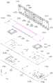
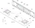
图1A及图1B分别为本发明一实施例的按键结构的爆炸图及部分组合图;1A and FIG. 1B are respectively an exploded view and a partial combined view of a key structure according to an embodiment of the present invention;

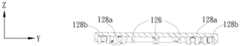
图1C至图1E分别为图1A的键帽的平面图及不同视角截面示意图;1C to 1E are a plan view of the keycap of FIG. 1A and a schematic cross-sectional view from different viewing angles, respectively;

图2A及图2B分别为图1A的按键结于构按压前的不同视角截面示意图;2A and FIG. 2B are schematic cross-sectional views of the key structure of FIG. 1A from different viewing angles before the structure is pressed;

图3A及图3B分别为图1A的按键结于构按压后的不同视角截面示意图;3A and FIG. 3B are respectively schematic cross-sectional views of the key structure of FIG. 1A after the structure is pressed;

图4A及图4B为本发明不同实施例的键帽的示意图;4A and 4B are schematic diagrams of keycaps according to different embodiments of the present invention;

图5A及图5B为本发明另一实施例的按键结构于按压前及按压后的截面示意图;5A and 5B are schematic cross-sectional views of a button structure before and after pressing according to another embodiment of the present invention;

图6A及图6B为本发明又一实施例的按键结构于按压前及按压后的截面示意图;以及6A and 6B are schematic cross-sectional views of a button structure before and after pressing according to yet another embodiment of the present invention; and

图7为本发明另一实施例的键帽的示意图。FIG. 7 is a schematic diagram of a keycap according to another embodiment of the present invention.

具体实施方式Detailed ways

为使对本发明的目的、构造、特征、及其功能有进一步的了解,兹配合实施例详细说明如下。In order to have a further understanding of the purpose, structure, features, and functions of the present invention, the following detailed descriptions are given in conjunction with the embodiments.

在说明书及权利要求书当中使用了某些词汇来指称特定的组件。所属领域中具有通常知识者应可理解,制造商可能会用不同的名词来称呼同一个组件。本说明书及权利要求书并不以名称的差异来作为区分组件的方式,而是以组件在功能上的差异来作为区分的准则。在通篇说明书及权利要求当中所提及的「包括」为开放式的用语,故应解释成「包括但不限定于」。Certain terms are used in the specification and claims to refer to particular components. It should be understood by those with ordinary knowledge in the art that manufacturers may refer to the same component by different nouns. The present specification and claims do not use the difference in name as a way to distinguish components, but use the difference in function of the components as a criterion for distinguishing. The "including" mentioned throughout the specification and claims is an open-ended term, so it should be interpreted as "including but not limited to".

本发明提供一种具有变形安全设计的按键结构。具体而言,本发明的按键结构可为计算机键盘的按键结构,但并不以此为。本发明的按键结构可为其他电子装置的按键、数字键等。本发明的按键结构可为任何具有弹性体的按键结构,尤其是具有较大长宽比的按键结构,例如倍数键,但不以此为限。参考图式详细说明本发明实施例的按键结构的细节。The invention provides a key structure with deformation safety design. Specifically, the key structure of the present invention may be the key structure of a computer keyboard, but it is not the case. The key structure of the present invention can be keys, numeric keys, etc. of other electronic devices. The key structure of the present invention can be any key structure with an elastic body, especially a key structure with a large aspect ratio, such as a multiple key, but not limited thereto. The details of the key structure of the embodiment of the present invention will be described in detail with reference to the drawings.

如图1A及图1B所示,于一实施例,本发明的按键结构100包含底板110、键帽120、弹性体130及开关层140。键帽120设置于底板110上方,且可相对于底板110上/下移动。弹性体130设置于底板110上方且位于键帽120及底板110之间,用以提供键帽120按压后回复到按压前位置的回复力。开关层140设置于弹性体130下方,且较佳位于底板110上,并具有开关电路用以提供触发信号。依据设计需求,本发明的按键结构100可进一步包含支撑单元150及辅助杆(例如加强杆162及平衡杆164)。支撑单元150设置于键帽120及底板110之间,且支撑单元150的两端分别可活动地连接键帽120及底板110,用以支撑键帽120相对于底板110的上/下移动。辅助杆设置于键帽120及底板110之间,可用于加强键帽120的结构强度或者用于加强键帽120的带动性。As shown in FIGS. 1A and 1B , in one embodiment, thekey structure 100 of the present invention includes abottom plate 110 , akey cap 120 , anelastic body 130 and aswitch layer 140 . Thekeycap 120 is disposed above thebottom plate 110 and can move up/down relative to thebottom plate 110 . Theelastic body 130 is disposed above thebottom plate 110 and between thekey cap 120 and thebottom plate 110 , and is used to provide a restoring force for thekey cap 120 to return to the position before pressing after being pressed. Theswitch layer 140 is disposed under theelastic body 130 , preferably on thebottom plate 110 , and has a switch circuit for providing a trigger signal. According to design requirements, thekey structure 100 of the present invention may further include asupport unit 150 and an auxiliary rod (eg, a reinforcingrod 162 and a balance rod 164 ). The supportingunit 150 is disposed between thekeycap 120 and thebottom plate 110 , and two ends of the supportingunit 150 are respectively movably connected to thekeycap 120 and thebottom plate 110 to support the up/down movement of thekeycap 120 relative to thebottom plate 110 . The auxiliary rod is disposed between thekeycap 120 and thebottom plate 110 , and can be used to strengthen the structural strength of thekeycap 120 or to enhance the driveability of thekeycap 120 .

举例而言,加强杆162仅连接于键帽120,以用于加强目前薄型化后塑料键帽120的结构强度。加强杆162较佳为非封闭式框形杆,例如于两末端之间具有开口162a的矩形框平衡杆,以增加加强杆162的变形弹性,进而提升加强杆162与键帽120组装连接时的便利性。平衡杆164上下端分别连接于键帽120及底板110之间,亦即平衡杆164一侧连接于键帽120,另一侧连接于底板110,可用于加强键帽120的带动性。如此当使用者只按压键帽右侧时,键帽左侧也能一起同时下降,避免键帽120呈现右侧较低,左侧较高的倾斜状态。于此实施例,平衡杆164为U形杆,且于U形两端具有朝U形开口弯折的延伸部164a,其中延伸部164a作为与底板110可滑动地卡合的卡勾。再者,加强杆162、平衡杆164较佳具有圆形杆身且可由金属线弯折制成,但不以此为限。于其他实施例,依据设计需求,加强杆162、平衡杆164可具有椭圆形、方形等形状的杆身,且可由任何合宜的材料制成以增进键帽120的强度或加强键帽120的带动性。For example, thereinforcing rod 162 is only connected to thekeycap 120 for enhancing the structural strength of the currently thinnedplastic keycap 120 . The reinforcingrod 162 is preferably a non-closed frame rod, such as a rectangular frame balance rod with an opening 162a between the two ends, so as to increase the deformation elasticity of thereinforcing rod 162, thereby increasing the strength of the reinforcingrod 162 when it is assembled and connected with thekeycap 120. Convenience. The upper and lower ends of thebalance bar 164 are respectively connected between thekeycap 120 and thebottom plate 110 , that is, one side of thebalance bar 164 is connected to thekeycap 120 and the other side is connected to thebottom plate 110 , which can be used to enhance the driving ability of thekeycap 120 . In this way, when the user only presses the right side of the keycap, the left side of the keycap can also descend at the same time, so as to prevent thekeycap 120 from presenting a tilted state in which the right side is lower and the left side is higher. In this embodiment, thebalance rod 164 is a U-shaped rod, and hasextension portions 164a bent toward the U-shaped opening at both ends of the U-shape, wherein theextension portions 164a serve as hooks slidably engaged with thebottom plate 110 . Furthermore, the reinforcingrod 162 and thebalance rod 164 preferably have round shafts and can be made by bending metal wires, but not limited thereto. In other embodiments, according to design requirements, the reinforcingrod 162 and thebalance rod 164 can have oval, square and other shapes of shafts, and can be made of any suitable material to enhance the strength of thekeycap 120 or enhance the driving force of thekeycap 120 . sex.

具体而言,底板沿着X轴与Y轴平面延伸,且X轴、Y轴与Z轴相互垂直。底板110具有凹陷空间112。凹陷空间112可为形成于底板110的破孔或凹槽所构成。于一实施例,凹陷空间112较佳为贯穿底板110的破孔所构成,以使得底板110在厚度方向(即键帽120的移动方向)上具有最大的容置空间,但不以此为限。于其他实施例,凹陷空间112可为自底板110的上表面朝远离键帽120的方向(即向下)凹陷而成的凹槽所构成,即凹陷空间112为形成于底板110的盲孔所构成。如稍后所详述,键帽120具有结合部(例如第一结合部128a及第二结合部128b),凹陷空间112对应键帽120的结合部设置。当键帽120朝底板110移动时,凹陷空间112作为结合部(128a、128b)的避让区,可容许结合部伸入凹陷空间112。Specifically, the base plate extends along the X axis and the Y axis plane, and the X axis, the Y axis and the Z axis are perpendicular to each other. Thebottom plate 110 has a recessedspace 112 . The recessedspace 112 may be formed by holes or grooves formed in thebottom plate 110 . In one embodiment, the recessedspace 112 is preferably formed by a hole passing through thebottom plate 110 , so that thebottom plate 110 has the largest accommodating space in the thickness direction (ie, the moving direction of the keycap 120 ), but not limited to this. . In other embodiments, the recessedspace 112 may be formed by a recess formed from the upper surface of thebase plate 110 in a direction away from the keycap 120 (ie downward), that is, the recessedspace 112 is formed by the blind holes formed in thebase plate 110 . constitute. As described in detail later, thekeycap 120 has a joint portion (eg, a firstjoint portion 128 a and a secondjoint portion 128 b ), and the recessedspace 112 is provided corresponding to the joint portion of thekeycap 120 . When thekeycap 120 moves toward thebottom plate 110 , theconcave space 112 serves as an escape area for the joint portion ( 128 a , 128 b ), allowing the joint portion to protrude into theconcave space 112 .

此外,对应于支撑单元150的设置,底板110进一步具有至少一第一耦接部114a、114b,以耦接支撑单元150。举例而言,复数卡勾自底板110的上表面朝键帽120方向(即向上)突起,以作为耦接支撑单元150的第一耦接部114a、114b,但不以此为限。于其他实施例,第一耦接部114a、114b可依据支撑单元150的结构而有不同的变化。底板110可由金属板机械加工弯折或由塑料模铸而形成具有凹陷空间112及第一耦接部114a、114b的一体结构,但不以此为限。于其他实施例,第一耦接部114a、114b可藉由黏着、焊接、锁固等方式设置于底板110。In addition, corresponding to the arrangement of the supportingunit 150 , thebottom plate 110 further has at least onefirst coupling portion 114 a and 114 b for coupling to the supportingunit 150 . For example, the plurality of hooks protrude from the upper surface of thebottom plate 110 toward the keycap 120 (ie upward) to serve as thefirst coupling portions 114 a and 114 b of thecoupling support unit 150 , but not limited thereto. In other embodiments, thefirst coupling portions 114 a and 114 b may vary according to the structure of thesupport unit 150 . Thebottom plate 110 can be machined and bent from a metal plate or molded from plastic to form an integrated structure having theconcave space 112 and thefirst coupling portions 114a and 114b, but not limited thereto. In other embodiments, thefirst coupling portions 114a and 114b may be disposed on thebottom plate 110 by means of adhesion, welding, and locking.

底板110除上述的凹陷空间112及第一耦接部114a、114b外,还具有与平衡杆164的延伸部164a卡合的连接部116。于此实施例,连接部116为自底板110表面向上弯折的连接机构,其中连接部116具有滑槽116a。在此需注意,当开关层140设置于底板110上时,开关层140具有相应的开口142,以容许第一耦接部114a、114b及/或连接部116自开口142伸出,以使第一耦接部114a、114b可与支撑单元150活动地耦接,且平衡杆164的延伸部164a可滑动地插入滑槽116a中。当键帽120相对于底板110移动时,延伸部164a于滑槽116a中移动,以增进键帽120移动的平衡性。In addition to the above-mentioned recessedspace 112 and thefirst coupling portions 114 a and 114 b , thebottom plate 110 also has a connectingportion 116 that is engaged with the extendingportion 164 a of thebalance rod 164 . In this embodiment, the connectingportion 116 is a connecting mechanism bent upward from the surface of thebottom plate 110 , wherein the connectingportion 116 has a slidinggroove 116 a. It should be noted here that when theswitch layer 140 is disposed on thebottom plate 110, theswitch layer 140 has correspondingopenings 142 to allow thefirst coupling parts 114a, 114b and/or the connectingparts 116 to protrude from theopenings 142, so that the secondA coupling portion 114a, 114b can be movably coupled with thesupport unit 150, and theextension portion 164a of thebalance rod 164 is slidably inserted into the slidingslot 116a. When thekeycap 120 moves relative to thebottom plate 110 , the extendingportion 164a moves in the slidinggroove 116a to improve the balance of the movement of thekeycap 120 .

于一实施例,开关层140较佳为包含上电路层、下电路层的多层电路结构,以使得上电路层可受压变形与下电路层电导通而产生触发信号。再者,开关层140对应凹陷空间112的位置可选择性开设通孔144,以容许结合部(例如第一结合部128a及第二结合部128b)通过通孔144进入凹陷空间112。于另一实施例,当开关层140对应凹陷空间112的部分具有可变形特性时,可不设置通孔144,以使得结合部向下移动时压抵开关层140对应凹陷空间112的部分,而使该部分变形以容许结合部进入凹陷空间112。在此需注意,底板110的凹陷空间112及开关层140的通孔144可具有适当的尺寸及位置,而使得邻近的第一结合部128a及第二结合部128b可对应同一通孔144,进而可进入同一凹陷空间112,但不以此为限。于其他实施例,底板110的凹陷空间112及开关层140的通孔144可与第一结合部128a及第二结合部128b形成个别的对应,以使第一结合部128a及第二结合部128b对应不同的通孔144,进而可延伸进入对应的凹陷空间112。In one embodiment, theswitch layer 140 preferably has a multi-layer circuit structure including an upper circuit layer and a lower circuit layer, so that the upper circuit layer can be deformed under pressure and electrically conduct with the lower circuit layer to generate a trigger signal. Furthermore, throughholes 144 may be selectively formed in theswitch layer 140 corresponding to the recessedspace 112 , so as to allow the bonding portions (eg, thefirst bonding portion 128 a and thesecond bonding portion 128 b ) to enter the recessedspace 112 through the throughholes 144 . In another embodiment, when the part of theswitch layer 140 corresponding to the recessedspace 112 has a deformable property, the throughhole 144 may not be provided, so that when the bonding part moves downward, the part of theswitch layer 140 corresponding to the recessedspace 112 is pressed against the part of theswitch layer 140 corresponding to the recessedspace 112 . The portion deforms to allow the joint to enter the recessedspace 112 . It should be noted here that the recessedspace 112 of thebottom plate 110 and the throughhole 144 of theswitch layer 140 may have appropriate sizes and positions, so that the adjacentfirst bonding portion 128a and thesecond bonding portion 128b may correspond to the same throughhole 144, and further The same recessedspace 112 can be entered, but not limited thereto. In other embodiments, the recessedspace 112 of thebottom plate 110 and the throughhole 144 of theswitch layer 140 may correspond to the firstjoint portion 128a and the secondjoint portion 128b, so that the firstjoint portion 128a and the secondjoint portion 128b Corresponding to the different throughholes 144 , they can extend into the corresponding recessedspaces 112 .

如图1A至图1E所示,其中图1C为键帽120的平面示意图,图1D为键帽120沿键帽长轴(即X轴)的切线的截面示意图,且图1E为键帽120沿键帽短轴(即Y轴)的切线的截面示意图。键帽120是由键顶122及连接于键顶122周围并朝底板110延伸的键裙124所构成。键帽120具有限位部126、第二耦接部127a、127b及第一结合部128a与第二结合部128b。限位部126、第二耦接部127a、127b及第一结合部128a与第二结合部128b分别自键顶122的下表面122a朝底板110突出,且限位部126及第一结合部128a与第二结合部128b较佳向下延伸超过键裙124的底表面,而使得限位部126及第一结合部128a与第二结合部128b的下端点突出键裙124的底表面。限位部126对应弹性体130设置,且第一结合部128a与第二结合部128b较限位部126接近邻近的键裙124。限位部126用于界定键帽120相对于底板110移动的距离(即按键行程),并确保弹性体130在键帽120朝底板110向下移动时具有安全的变形量,而不会过度变形(于后详述)。As shown in FIGS. 1A to 1E , wherein FIG. 1C is a schematic plan view of thekeycap 120 , FIG. 1D is a schematic cross-sectional view of thekeycap 120 along the tangent line of the keycap long axis (ie, the X axis), and FIG. 1E is a schematic diagram of thekeycap 120 along the tangent line. A schematic cross-sectional view of the tangent to the short axis of the keycap (ie, the Y axis). Thekey cap 120 is composed of akey top 122 and akey skirt 124 connected around thekey top 122 and extending toward thebottom plate 110 . Thekeycap 120 has a limitingportion 126,second coupling portions 127a, 127b, and a first combiningportion 128a and a second combiningportion 128b. The limitingportion 126 , thesecond coupling portions 127 a , 127 b and the first combiningportion 128 a and the second combiningportion 128 b respectively protrude from thelower surface 122 a of the key top 122 toward thebottom plate 110 , and the limitingportion 126 and the first combiningportion 128 a The secondjoint portion 128b preferably extends downward beyond the bottom surface of thekey skirt 124 , so that the lower end points of the limitingportion 126 and the firstjoint portion 128a and the secondjoint portion 128b protrude from the bottom surface of thekey skirt 124 . The limitingportion 126 is disposed corresponding to theelastic body 130 , and thefirst coupling portion 128 a and thesecond coupling portion 128 b are closer to the adjacentkey skirts 124 than the limitingportion 126 . The limitingportion 126 is used to define the distance that thekeycap 120 moves relative to the base plate 110 (ie, the key stroke), and to ensure that theelastic body 130 has a safe deformation amount when thekeycap 120 moves downward toward thebase plate 110 without excessive deformation (described in detail later).

第一结合部128a及第二结合部128b分别用于连接加强杆162及平衡杆164。举例而言,键帽120具有复数个第一结合部128a,且复数个结合部128a对应加强杆162的框形轮廓设置于键顶122的下表面122a,以分别连接加强杆162的对应杆身部分。换言之,复数个第一结合部128a以框形分布的方式设置于键顶122的下表面122a。类似地,相应于平衡杆164的构形,复数个第二结合部128b对应平衡杆164设置于键顶122的下表面122a,以分别连接平衡杆164的对应杆身部分。于此实施例,平衡杆164较佳设置于加强杆162的外侧,亦即第二结合部128b较第一结合部128a靠近邻近的键裙124。在此需注意,当加强杆162与第一结合部128a,或平衡杆164与第二结合部128b卡合时,第一结合部128a的下端点低于加强杆162的下端点,或第二结合部128b的下端点低于平衡杆164的下端点。亦即,第一结合部128a的下端点实质低于加强杆162与第一结合部128a连接的部分,或第二结合部128b的下端点实质低于平衡杆164与第二结合部128b连接的部分。The firstjoint portion 128a and the secondjoint portion 128b are used to connect the reinforcingrod 162 and thebalance rod 164, respectively. For example, thekeycap 120 has a plurality of firstjoint portions 128a, and the plurality ofjoint portions 128a are disposed on thelower surface 122a of the key top 122 corresponding to the frame-shaped outline of the reinforcingrod 162, so as to be respectively connected to the corresponding shafts of the reinforcingrod 162 part. In other words, the plurality offirst coupling portions 128a are disposed on thelower surface 122a of the key top 122 in a frame-shaped distribution. Similarly, corresponding to the configuration of thebalance bar 164 , a plurality ofsecond coupling parts 128 b are disposed on thelower surface 122 a of the key top 122 corresponding to thebalance bar 164 to connect the corresponding shaft parts of thebalance bar 164 respectively. In this embodiment, thebalance rod 164 is preferably disposed on the outer side of the reinforcingrod 162 , that is, the secondjoint portion 128b is closer to the adjacentkey skirt 124 than the firstjoint portion 128a. It should be noted here that when the reinforcingrod 162 is engaged with the firstjoint portion 128a, or thebalance rod 164 is engaged with the secondjoint portion 128b, the lower end of the firstjoint portion 128a is lower than the lower end of the reinforcingrod 162, or the second The lower end point of thejoint portion 128b is lower than the lower end point of thebalance bar 164 . That is, the lower end point of the firstjoint portion 128a is substantially lower than the portion where the reinforcingrod 162 is connected with the firstjoint portion 128a, or the lower end point of the secondjoint portion 128b is substantially lower than the portion where thebalance rod 164 is connected with the secondjoint portion 128b part.

于此实施例,两个支撑单元150分别设置于键帽120长轴方向的相对两侧,即相对于弹性体130设置于X轴的相对两侧。各支撑单元150可包含第一支架152及第二支架154,其中第一支架152可转动地枢接第二支架154以形成剪刀式支撑单元,但不以此为限。具体而言,第一支架152的一端与键帽120的第二耦接部127a可转动地连接,第一支架152的另一端与底板110的第一耦接部114a可移动地连接。第二支架154的一端与键帽120的第二耦接部127b可移动地连接,第二支架154的另一端与底板110的第一耦接部114b可转动地连接。在此需注意,于其他实施例,支撑单元可为由第一支架及第二支架构成的蝶式支撑单元,以使得第一支架及第二支架分别与键帽及底板可转动地及可滑动地耦接。In this embodiment, the two supportingunits 150 are respectively disposed on opposite sides of the long axis direction of thekeycap 120 , that is, disposed on opposite sides of the X-axis relative to theelastic body 130 . Eachsupport unit 150 may include afirst bracket 152 and asecond bracket 154 , wherein thefirst bracket 152 is rotatably pivoted to thesecond bracket 154 to form a scissor-type support unit, but not limited thereto. Specifically, one end of thefirst bracket 152 is rotatably connected to thesecond coupling portion 127 a of thekeycap 120 , and the other end of thefirst bracket 152 is movably connected to thefirst coupling portion 114 a of thebottom plate 110 . One end of thesecond bracket 154 is movably connected to thesecond coupling portion 127b of thekeycap 120 , and the other end of thesecond bracket 154 is rotatably connected to thefirst coupling portion 114b of thebottom plate 110 . It should be noted here that in other embodiments, the support unit may be a butterfly support unit composed of a first bracket and a second bracket, so that the first bracket and the second bracket are rotatably and slidably connected to the keycap and the bottom plate, respectively ground coupling.

弹性体130设置于键帽120及底板110之间,且较佳对应于键顶122的中央位置。再者,于此实施例,弹性体130为圆顶状的橡胶弹性体。弹性体130较佳具有触发部132(参见图2A),且触发部132设置于弹性体130内部空间中并朝底板110向下延伸。当按键结构100处于未按压位置时(即按压键帽120前),弹性体130较佳顶接键顶122的下表面122a,且在Z轴方向上,弹性体130于键顶122的下表面122a具有投影范围P。如图1C及图2A所示,限位部126对应弹性体130设置,而使得限位部126与投影范围P具有预设距离(例如D1、D2)。预设距离D1、D2的设计较佳需兼顾考虑两种作用:(1)当键帽120被按压,弹性体130被压扁变形侧向延伸时,要避免弹性体130侧向延伸进入到限位部126和底板110间,影响使用者操作手感;因此预设距离D1、D2需大于预设最小值,确保有足够空间让弹性体130侧向延伸;(2)当键帽120被按压时,不会因为限位部126间的薄型化键帽120呈现中央较低两侧较高的U字形形变,而造成键帽120中央较低处过度挤压而造成弹性体130过度变形损伤;因此预设距离D1、D2需小于预设最大值,以控制键帽120中央较低处变形量。Theelastic body 130 is disposed between thekey cap 120 and thebottom plate 110 , and preferably corresponds to the central position of thekey top 122 . Furthermore, in this embodiment, theelastic body 130 is a dome-shaped rubber elastic body. Theelastic body 130 preferably has a trigger portion 132 (see FIG. 2A ), and thetrigger portion 132 is disposed in the inner space of theelastic body 130 and extends downward toward thebottom plate 110 . When thekey structure 100 is in the unpressed position (ie before pressing the key cap 120 ), theelastic body 130 preferably abuts against thelower surface 122 a of thekey top 122 , and in the Z-axis direction, theelastic body 130 is on the lower surface of the key top 122 122a has a projection range P. As shown in FIG. 1C and FIG. 2A , the limitingportion 126 is disposed corresponding to theelastic body 130 , so that the limitingportion 126 and the projection range P have a predetermined distance (eg, D1 , D2 ). The design of the preset distances D1 and D2 should preferably take into account two functions: (1) When thekeycap 120 is pressed and theelastic body 130 is crushed and deformed to extend laterally, it is necessary to prevent theelastic body 130 from extending laterally into the limit. The position between theposition 126 and thebottom plate 110 affects the user's operating feel; therefore, the preset distances D1 and D2 must be greater than the preset minimum value to ensure that there is enough space for theelastic body 130 to extend laterally; (2) When thekeycap 120 is pressed , because the thinnedkeycap 120 between the limitingportions 126 exhibits a U-shaped deformation with a lower center and higher sides on both sides, which will cause excessive extrusion of the lower center of thekeycap 120 and cause excessive deformation and damage of theelastic body 130; therefore The preset distances D1 and D2 need to be smaller than the preset maximum value, so as to control the deformation amount at the lower center of thekeycap 120 .

具体而言,限位部126的下端移动至压抵底板110(或接触开关层140进而透过开关层140压抵底板110)的距离实质为按键行程。再者,限位部126与投影范围P之间的距离决定了键帽120对应弹性体130的部分的变形能力,进而界定了键帽120的形变对弹性体130变形的影响程度。因此,预设距离D1、D2较佳定义为限位部126相对于投影范围P设置而使得键帽120对应弹性体130的部分实质没有变形而不显著影响弹性体130变形的距离。换言之,限位部126较佳尽可能的设置靠近弹性体130,以加强键帽120的局部刚性降低键帽120局部变形的可能性,但又确保弹性体130具有默认的变形量而不会过度变形,且变形后的弹性体130也不会与限位部126发生干涉。Specifically, the distance that the lower end of the limitingportion 126 moves to press against the bottom plate 110 (or contacts theswitch layer 140 and then presses against thebottom plate 110 through the switch layer 140 ) is substantially the key stroke. Furthermore, the distance between the limitingportion 126 and the projection range P determines the deformation ability of the part of thekeycap 120 corresponding to theelastic body 130 , and further defines the degree of influence of the deformation of thekeycap 120 on the deformation of theelastic body 130 . Therefore, the preset distances D1 and D2 are preferably defined as the distances at which the limitingportion 126 is set relative to the projection range P so that the portion of thekeycap 120 corresponding to theelastic body 130 is substantially not deformed without significantly affecting the deformation of theelastic body 130 . In other words, the limitingportion 126 is preferably disposed as close to theelastic body 130 as possible, so as to strengthen the local rigidity of thekeycap 120 and reduce the possibility of local deformation of thekeycap 120, but also ensure that theelastic body 130 has a default deformation amount without excessive deformation, and the deformedelastic body 130 will not interfere with the limitingportion 126 .

限位部126可包含复数凸肋或凸柱,且复数凸肋或凸柱较佳沿投影范围P的周围设置。如图1A及图1C所示,限位部126实施为六个凸肋,且分成两列分别设置于投影范围P沿键帽120的长轴方向(即X轴方向)的相对两侧,例如左、右两侧沿Y轴方向各设置三个凸肋。以另一观点而言,限位部126可包含第一限位部(即左侧凸肋)及第二限位部(右侧凸肋),且第一限位部与第二限位部分别设置于投影范围P的相对两侧。第一限位部及第二限位部彼此距离决定当键帽120被按压时,键顶122于Z轴方向上的最大下压变形量。再者,于一实施例中,第一限位部及第二限位部彼此距离较佳小于或等于弹性体130的直径加4mm。换言之,左侧凸肋与右侧凸肋间的距离较佳小于或等于投影范围P在X轴方向的宽度加4mm,例如D1+D2≦4mm。于此实施例中,复数凸肋较佳对称设置于投影范围P沿键帽120的长轴方向(即X轴方向)的相对两侧,使得左、右两侧的预设距离D1、D2实质相同(即D1=D2),但不以此为限。于另一实施例,如图4A所示,键帽120’的限位部126’实施为多个凸柱,且沿着投影范围P的周边环状设置。如于又一实施例,图4B所示,键帽120”的限位部126”实施为限位环,且限位环环绕投影范围P。于图4A的实施例中,环状设置的多个凸柱相对于投影范围P的中心(或形心)的距离(例如径向距离)较佳实质相同。于图4B的实施例中,限位环的中心(或形心)的位置较佳与投影范围P的中心(或形心)的位置相同,但不以此为限。The limitingportion 126 may include a plurality of protruding ribs or protruding posts, and the plurality of protruding ribs or protruding posts are preferably disposed along the periphery of the projection range P. As shown in FIG. As shown in FIG. 1A and FIG. 1C , the limitingportion 126 is implemented as six protruding ribs, and is divided into two rows and disposed on opposite sides of the projection range P along the long axis direction of the keycap 120 (ie, the X axis direction), for example Three protruding ribs are respectively provided on the left and right sides along the Y-axis direction. From another point of view, the limitingportion 126 may include a first limiting portion (ie, a left-side convex rib) and a second limiting portion (right-side convex rib), and the first limiting portion and the second limiting portion They are arranged on opposite sides of the projection range P, respectively. The distance between the first limiting portion and the second limiting portion determines the maximum depression deformation amount of the key top 122 in the Z-axis direction when thekeycap 120 is pressed. Furthermore, in one embodiment, the distance between the first limiting portion and the second limiting portion is preferably less than or equal to the diameter of theelastic body 130 plus 4 mm. In other words, the distance between the left protruding rib and the right protruding rib is preferably less than or equal to the width of the projection range P in the X-axis direction plus 4 mm, for example, D1+D2≦4mm. In this embodiment, the plurality of protruding ribs are preferably symmetrically arranged on opposite sides of the projection range P along the long axis direction of the keycap 120 (ie, the X axis direction), so that the preset distances D1 and D2 between the left and right sides are substantially equal to each other. The same (ie D1=D2), but not limited thereto. In another embodiment, as shown in FIG. 4A , the limiting portion 126' of the keycap 120' is implemented as a plurality of protruding posts, and is annularly arranged along the periphery of the projection range P. In yet another embodiment, as shown in FIG. 4B , the limitingportion 126 ″ of thekeycap 120 ″ is implemented as a limiting ring, and the limiting ring surrounds the projection range P. In the embodiment of FIG. 4A , the distances (eg, radial distances) of the plurality of annularly disposed convex pillars relative to the center (or centroid) of the projection range P are preferably substantially the same. In the embodiment of FIG. 4B , the position of the center (or centroid) of the limiting ring is preferably the same as the position of the center (or centroid) of the projection range P, but not limited thereto.

在此需注意,图1A所示实施例中虽以限位部126设置于投影范围P在X轴方向上的相对两侧,但不以此为限。依据实际应用,限位部126可仅设置于单侧,或同时设置于投影范围P在X轴及Y轴的相对侧(即四个侧边)。再者,于一实施例,预设距离D1、D2较佳小于或等于2mm。于另一实施例,预设距离D1、D2较佳大于或等于1mm。于又一实施例,预设距离D1、D2较佳大于或等于1mm且小于或等于2mm,但不以此为限。It should be noted here that in the embodiment shown in FIG. 1A , although the limitingportions 126 are disposed on opposite sides of the projection range P in the X-axis direction, it is not limited thereto. According to practical applications, the limitingportion 126 can be disposed on only one side, or can be disposed on the opposite sides (ie, four sides) of the projection range P on the X-axis and the Y-axis at the same time. Furthermore, in one embodiment, the predetermined distances D1 and D2 are preferably less than or equal to 2 mm. In another embodiment, the predetermined distances D1 and D2 are preferably greater than or equal to 1 mm. In another embodiment, the preset distances D1 and D2 are preferably greater than or equal to 1 mm and less than or equal to 2 mm, but not limited thereto.

于后参考图2A~图2B及图3A~图3B,说明本发明的按键结构100的操作,其中图2A及图3A为按键结构100沿键帽长轴(即X轴)的切线的截面示意图,且图2B及图3B为按键结构100沿键帽短轴(即Y轴)的切线的截面示意图。如图2A及图2B所示,当按键结构100处于未按压位置(即最高位置)时,弹性体130的顶端顶接于键顶122的下表面122a并且实质无形变产生,且弹性体130于键顶122的下表面122a具有投影范围P。如图3A及图3B所示,当键帽120被按压朝底板110移动时,键顶122的下表面122a压抵弹性体130,以使弹性体130弹性变形,第一结合部128a、第二结合部128b进入对应的凹陷空间112中,且限位部126压抵底板110以界定键帽120的最低位置。当键帽120位于最低位置时,弹性体130变形后并未超出预设距离D1、D2,使弹性体130变形后不会延伸到限位部126的下方。具体而言,当键帽120被按压朝底板110移动时,键顶122的下表面122a压抵弹性体130,而使弹性体130弹性变形,进而使得触发部132抵接开关层140,导致开关层140的上电路层受压变形而与下电路层电导通以产生触发信号。也就是说,当键帽120朝底板110向下移动到限位部126透过开关层140压抵底板110(即最低位置)时,键帽120即无法再向下移动,且键帽120对应弹性体130的投影范围P的部分实质无变形而不会对弹性体130的变形有显著的影响,且键帽120的向下移动带动第一结合部128a、第二结合部128b也向下移动而部分进入对应的凹陷空间112。因此,由于限位部126的变形安全设计强化键帽120对应弹性体130的局部结构强度,降低键帽120的变形可能性,进而避免键帽120的形变过度挤压弹性体130,使得弹性体130因受到键顶122的下表面122a压抵所产生的弹性变形是在默认的变形量范围内,而不会产生过度变形进而减少弹性体130损坏(或按键结构100失效)的机会。2A-2B and FIGS. 3A-3B, the operation of thekey structure 100 of the present invention is described, wherein FIG. 2A and FIG. 3A are schematic cross-sectional views of thekey structure 100 along the tangent of the long axis of the keycap (ie, the X axis). 2B and FIG. 3B are schematic cross-sectional views of thekey structure 100 along the tangent of the short axis of the keycap (ie, the Y axis). As shown in FIG. 2A and FIG. 2B , when thekey structure 100 is in the unpressed position (ie, the highest position), the top end of theelastic body 130 is abutted against thelower surface 122 a of thekey top 122 and substantially no deformation occurs, and theelastic body 130 is at the bottom of thekey top 122 . Thelower surface 122a of thekey top 122 has a projection range P. As shown in FIG. As shown in FIGS. 3A and 3B , when thekeycap 120 is pressed to move toward thebottom plate 110 , thelower surface 122 a of the key top 122 presses against theelastic body 130 to elastically deform theelastic body 130 . Thejoint portion 128b enters the corresponding recessedspace 112 , and the limitingportion 126 presses against thebottom plate 110 to define the lowest position of thekeycap 120 . When thekeycap 120 is located at the lowest position, theelastic body 130 does not exceed the preset distances D1 and D2 after deformation, so that theelastic body 130 does not extend below the limitingportion 126 after deformation. Specifically, when thekeycap 120 is pressed to move toward thebottom plate 110 , thelower surface 122 a of the key top 122 presses against theelastic body 130 , so that theelastic body 130 is elastically deformed, so that thetrigger portion 132 abuts theswitch layer 140 , causing the switch The upper circuit layer of thelayer 140 is compressively deformed and electrically connected to the lower circuit layer to generate a trigger signal. That is to say, when thekeycap 120 moves downward toward thebottom plate 110 until the limitingportion 126 presses against thebottom plate 110 through the switch layer 140 (ie, the lowest position), thekeycap 120 can no longer move downward, and thekeycap 120 corresponds to The part of the projection range P of theelastic body 130 is substantially free of deformation and does not have a significant impact on the deformation of theelastic body 130, and the downward movement of thekeycap 120 drives the firstjoint portion 128a and the secondjoint portion 128b to move downward. Part of it enters the corresponding recessedspace 112 . Therefore, due to the deformation safety design of the limitingportion 126, the local structural strength of thekeycap 120 corresponding to theelastic body 130 is strengthened, and the possibility of deformation of thekeycap 120 is reduced, thereby preventing the deformation of thekeycap 120 from excessively squeezing theelastic body 130, so that the elastic body The elastic deformation of 130 due to being pressed against thelower surface 122a of thekey top 122 is within the default deformation range, and will not cause excessive deformation to reduce the chance of damage to the elastic body 130 (or failure of the key structure 100).

在此需注意,于上述的实施例中虽以倍数键说明本发明的按键结构,但依据实际需求,本发明的按键结构可具有不同的态样。如图5A及图5B所示,于另一实施例,本发明的按键结构200包含底板210、键帽220、弹性体230、开关层240及辅助杆260。类似于上述实施例,底板210具有凹陷空间212;弹性体230设置于底板210上方;开关层240设置于弹性体130下方,且较佳位于底板210上。键帽220设置于弹性体230上方,且键帽220由键顶及连接于键顶周围的键裙所构成。键帽220具有限位部226及结合部228,其中限位部226及结合部228自键顶的下表面朝底板210突出,且结合部228对应凹陷空间212。在Z轴方向上,按压键帽220前,弹性体230于键顶的下表面具有投影范围。限位部226对应弹性体230设置,且限位部226与投影范围具有预设距离(例如D1、D2)。换句话说,预设距离D1、D2为限位部226相对于投影范围设置,而使弹性体230被键帽220下移压抵产生安全变形量(即未过度变形)的距离。在此需注意,底板210、键帽220、弹性体230、开关层240及辅助杆260的结构细节可对应参考图1A的实施例的相关说明,于此不再赘述。再者,依据实际应用,辅助杆260可对应于加强杆162或平衡杆164,以加强键帽220的结构强度或者用于加强键帽220的带动性。It should be noted here that although multiple keys are used to illustrate the key structure of the present invention in the above-mentioned embodiments, the key structure of the present invention may have different aspects according to actual needs. As shown in FIGS. 5A and 5B , in another embodiment, thekey structure 200 of the present invention includes abottom plate 210 , akey cap 220 , anelastic body 230 , aswitch layer 240 and anauxiliary rod 260 . Similar to the above-mentioned embodiment, thebottom plate 210 has aconcave space 212 ; theelastic body 230 is disposed above thebottom plate 210 ; Thekeycap 220 is disposed above theelastic body 230, and thekeycap 220 is composed of a key top and a key skirt connected around the key top. Thekeycap 220 has a limitingportion 226 and acoupling portion 228 , wherein the limitingportion 226 and thecoupling portion 228 protrude from the lower surface of the key top toward thebottom plate 210 , and thecoupling portion 228 corresponds to the recessedspace 212 . In the Z-axis direction, before thekey cap 220 is pressed, theelastic body 230 has a projection range on the lower surface of the key top. The limitingportion 226 is disposed corresponding to theelastic body 230 , and the limitingportion 226 has a predetermined distance (eg, D1 , D2 ) from the projection range. In other words, the preset distances D1 and D2 are the distances at which the limitingportion 226 is set relative to the projection range so that theelastic body 230 is pressed down by thekeycap 220 to generate a safe deformation amount (ie, no excessive deformation). It should be noted here that the structural details of thebottom plate 210 , thekey cap 220 , theelastic body 230 , theswitch layer 240 and theauxiliary rod 260 can correspond to the relevant description of the embodiment with reference to FIG. 1A , and will not be repeated here. Furthermore, according to practical applications, theauxiliary rod 260 may correspond to the reinforcingrod 162 or thebalance rod 164 to enhance the structural strength of thekeycap 220 or to enhance the driving ability of thekeycap 220 .

当键帽220被按压朝底板210移动时,键顶的下表面压抵弹性体230,以使弹性体230弹性变形,结合部228进入凹陷空间212中,且限位部226压抵底板210以界定键帽220的最低位置。当键帽210位于最低位置时,弹性体230变形后并未超出预设距离D1、D2,使弹性体230变形后不会延伸到限位部226下方。也就是说,当键帽220朝底板210向下移动到限位部226透过开关层240压抵底板210,即无法再向下移动而达到键帽220的最低位置,且键帽220的向下移动带动结合部228也向下移动而部分进入凹陷空间212中。此时,由于限位部226的变形安全设计强化键帽220的对应弹性体230的局部结构强度,降低键帽220的变形可能性,进而使得弹性体230因受到键顶的下表面的压抵所产生的弹性变形是在默认的变形量范围内,而不会产生过度变形进而减少损坏的机会。When thekeycap 220 is pressed to move toward thebottom plate 210 , the lower surface of the key top presses against theelastic body 230 to elastically deform theelastic body 230 , thejoint portion 228 enters the recessedspace 212 , and the limitingportion 226 presses against thebottom plate 210 to Defines the lowest position of thekeycap 220 . When thekeycap 210 is at the lowest position, theelastic body 230 does not exceed the preset distances D1 and D2 after deformation, so that theelastic body 230 does not extend below the limitingportion 226 after deformation. That is to say, when thekeycap 220 moves downward toward thebottom plate 210 until the limitingportion 226 presses against thebottom plate 210 through theswitch layer 240 , that is, thekeycap 220 can no longer move downward and reaches the lowest position of thekeycap 220 . The downward movement drives thejoint portion 228 to also move downward to partially enter the recessedspace 212 . At this time, due to the deformation safety design of the limitingportion 226, the local structural strength of the correspondingelastic body 230 of thekeycap 220 is strengthened, and the deformation possibility of thekeycap 220 is reduced, so that theelastic body 230 is pressed against by the lower surface of the keycap. The resulting elastic deformation is within the default deformation amount without excessive deformation and thus reducing the chance of damage.

如图6A及图6B所示,于另一实施例,本发明的按键结构300包含底板310、键帽320、弹性体330、开关层340及支撑单元350。底板310具有第一耦接部。键帽320可移动地设置于底板310上方,键帽320由键顶及连接于键顶周围的键裙所构成。键帽320具有限位部326及第二耦接部。限位部326及第二耦接部自键顶的下表面朝底板310突出。支撑单元350设置于键帽320及底板310之间,且支撑单元350的两端分别可活动地连接第二耦接部及第一耦接部。弹性体330设置于键帽320及底板310之间。弹性体330于键顶的下表面具有投影范围。限位部326对应弹性体330设置,且限位部326与投影范围具有预设距离(例如D1、D2)。开关层340设置于弹性体230下方且较佳位于底板310上。在此需注意,底板310、键帽320、弹性体330、开关层340及支撑单元350的结构细节可对应参考图1A的实施例的相关说明,于此不再赘述。As shown in FIGS. 6A and 6B , in another embodiment, thekey structure 300 of the present invention includes abottom plate 310 , akey cap 320 , anelastic body 330 , aswitch layer 340 and asupport unit 350 . Thebottom plate 310 has a first coupling portion. Thekeycap 320 is movably disposed above thebottom plate 310, and thekeycap 320 is composed of a key top and a key skirt connected around the key top. Thekeycap 320 has a limitingportion 326 and a second coupling portion. The limitingportion 326 and the second coupling portion protrude from the lower surface of the key top toward thebottom plate 310 . Thesupport unit 350 is disposed between thekeycap 320 and thebottom plate 310 , and two ends of thesupport unit 350 are respectively movably connected to the second coupling portion and the first coupling portion. Theelastic body 330 is disposed between thekeycap 320 and thebottom plate 310 . Theelastic body 330 has a projection range on the lower surface of the key top. The limitingportion 326 is disposed corresponding to theelastic body 330 , and the limitingportion 326 has a predetermined distance (eg, D1 , D2 ) from the projection range. Theswitch layer 340 is disposed under theelastic body 230 and preferably on thebottom plate 310 . It should be noted here that the structural details of thebottom plate 310 , thekey caps 320 , theelastic body 330 , theswitch layer 340 and thesupport unit 350 may correspond to the relevant description of the embodiment with reference to FIG. 1A , and will not be repeated here.

当键帽320被按压朝底板310移动时,键顶的下表面压抵弹性体330,以使弹性体330弹性变形,进而触发开关层340以产生触发信号,且限位部326透过开关层340压抵底板310以界定键帽320的最低位置。当键帽320位于最低位置时,弹性体330变形后并未超出预设距离D1、D2,使弹性体330变形后不会延伸到限位部326下方。也就是说,当键帽320朝底板310向下移动到限位部326透过开关层340压抵底板310,键帽320即无法再向下移动。此时,由于限位部326的变形安全设计,使得弹性体330因受到键顶的下表面的压抵所产生的弹性变形是在默认的变形量范围内,而不会产生过度变形进而减少损坏的机会。When thekeycap 320 is pressed to move toward thebottom plate 310, the lower surface of the keytop presses against theelastic body 330 to elastically deform theelastic body 330, thereby triggering theswitch layer 340 to generate a trigger signal, and the limitingportion 326 passes through theswitch layer 340 is pressed against thebottom plate 310 to define the lowest position of thekeycap 320 . When thekeycap 320 is at the lowest position, theelastic body 330 does not exceed the preset distances D1 and D2 after deformation, so that theelastic body 330 does not extend below the limitingportion 326 after deformation. That is, when thekeycap 320 moves downward toward thebottom plate 310 until the limitingportion 326 presses against thebottom plate 310 through theswitch layer 340 , thekeycap 320 cannot move downward any more. At this time, due to the deformation safety design of the limitingportion 326, the elastic deformation of theelastic body 330 due to the pressing of the lower surface of the key top is within the default deformation range, and excessive deformation will not occur to reduce damage. Opportunity.

此外,于一实施例,如图7所示,连接内侧的加强杆162的第一结合部128a的长度较佳大于或等于连接外侧的平衡杆164的第二结合部128b的长度。亦即,设置于键顶122的下表面122a内侧的第一结合部128a具有大于或等于外侧的第二结合部128b的长度。In addition, in one embodiment, as shown in FIG. 7 , the length of the firstjoint portion 128 a connecting the inner reinforcingrod 162 is preferably greater than or equal to the length of the secondjoint portion 128 b connecting theouter balance rod 164 . That is, thefirst coupling portion 128a disposed on the inner side of thelower surface 122a of thekey top 122 has a length greater than or equal to the length of the outersecond coupling portion 128b.

此外,于图1A所示的实施例中,虽绘示弹性体130对应设置于键帽120的中央位置,而两个支撑单元150分别设置于键帽120长轴方向的相对两侧,即相对于弹性体130设置于X轴的相对两侧,但不以此为限。于图6A及图6B的实施例中,支撑单元350较佳环绕弹性体330。举例而言,当支撑单元350为第一支架352及第二支架354枢接的剪刀式支撑单元时,而弹性体330可设置于作为内支架的第一支架352的框架开孔中。In addition, in the embodiment shown in FIG. 1A , although theelastic body 130 is shown correspondingly disposed at the central position of thekeycap 120 , the two supportingunits 150 are respectively disposed on opposite sides of the long axis direction of thekeycap 120 , that is, opposite to Theelastic bodies 130 are disposed on opposite sides of the X-axis, but not limited thereto. In the embodiment of FIG. 6A and FIG. 6B , thesupport unit 350 preferably surrounds theelastic body 330 . For example, when thesupport unit 350 is a scissor-type support unit in which the first bracket 352 and the second bracket 354 are pivotally connected, theelastic body 330 can be disposed in the frame opening of the first bracket 352 serving as the inner bracket.

相较于习知技术,本发明提供一种具有变形安全设计的按键结构,其藉由键帽上的限位部定义出相对于弹性体的预设距离,不仅可强化键帽的局部刚性,更可界定按压行程,以有效降低键帽形变而造成弹性体的过度变形,进而减少弹性体损坏(或按键结构失效)的机会。Compared with the prior art, the present invention provides a key structure with a deformation safety design, which defines a preset distance relative to the elastic body by the limiting portion on the keycap, which can not only strengthen the local rigidity of the keycap, but also Furthermore, the pressing stroke can be defined to effectively reduce the excessive deformation of the elastic body caused by the deformation of the keycap, thereby reducing the chance of the elastic body being damaged (or the failure of the key structure).

藉由以上较佳具体实施例的详述,是希望能更加清楚描述本发明的特征与精神,而并非以上述所揭露的较佳具体实施例来对本发明的保护范围加以限制。相反地,其目的是希望能涵盖各种改变及具相等性的安排于本发明所欲申请的权利要求的保护范围内。因此,本发明所申请的权利要求的保护范围应该根据上述的说明作最宽广的解释,以致使其涵盖所有可能的改变以及具相等性的安排。It is hoped that the features and spirit of the present invention can be described more clearly by the detailed description of the preferred embodiments above, rather than limiting the protection scope of the present invention by the preferred embodiments disclosed above. On the contrary, the intention is to cover various modifications and equivalent arrangements within the scope of the claims to which the present invention seeks to apply. Therefore, the scope of protection of the claims to which the present invention applies should be construed in the broadest sense in accordance with the foregoing description so as to encompass all possible changes and equivalent arrangements.

Claims (11)

when the key cap is pressed to move towards the bottom plate, the lower surface of the key top presses against the elastic body to enable the elastic body to be elastically deformed, the combining part enters the concave space, the limiting part presses against the bottom plate to limit the lowest position of the key cap, the bottom plate is not pressed against by the limiting part to deform downwards, and when the key is at the highest position, the limiting part surrounds the projection range in the X-axis direction and the Y-axis direction; when the key is at the lowest position, the limiting part surrounds the elastic body in the X-axis and Y-axis directions; when the keycap is located at the lowest position, the elastic body does not exceed the preset distance after being radially deformed, so that the elastic body cannot extend to the lower part of the limiting part after being deformed;
CN201710609683.4A2017-07-252017-07-25 Key structureActiveCN107492461B (en)

Priority Applications (1)

Application NumberPriority DateFiling DateTitle
CN201710609683.4ACN107492461B (en)2017-07-252017-07-25 Key structure

Applications Claiming Priority (1)

Application NumberPriority DateFiling DateTitle
CN201710609683.4ACN107492461B (en)2017-07-252017-07-25 Key structure

Publications (2)

Publication NumberPublication Date
CN107492461A CN107492461A (en)2017-12-19
CN107492461Btrue CN107492461B (en)2020-06-05

Family

ID=60644117

Family Applications (1)

Application NumberTitlePriority DateFiling Date
CN201710609683.4AActiveCN107492461B (en)2017-07-252017-07-25 Key structure

Country Status (1)

CountryLink
CN (1)CN107492461B (en)

Families Citing this family (5)

* Cited by examiner, † Cited by third party
Publication numberPriority datePublication dateAssigneeTitle
CN111292991B (en)*2018-12-072023-01-20秀育企业股份有限公司Reinforced press key
CN111710547A (en)*2019-09-212020-09-25光宝电子(广州)有限公司Key structure
US11424090B2 (en)2020-03-312022-08-23Darfon Electronics Corp.Keyswitch support connection structure and keyswitch structure therewith
TWI759945B (en)*2020-03-312022-04-01達方電子股份有限公司Keyswitch support connection structure and keyswitch structure therewith
TWI768921B (en)*2021-05-242022-06-21達方電子股份有限公司Keyswitch device

Citations (3)

* Cited by examiner, † Cited by third party
Publication numberPriority datePublication dateAssigneeTitle
CN204011186U (en)*2014-05-212014-12-10群光电子(苏州)有限公司The keyboard of button and applications keys
CN105261507A (en)*2015-08-192016-01-20东莞市美光达光学科技有限公司Thin keyboard on-off key group structure generating press touch feel and rebounded rapidly
CN105788924A (en)*2016-03-242016-07-20苏州达方电子有限公司Key structure

Family Cites Families (3)

* Cited by examiner, † Cited by third party
Publication numberPriority datePublication dateAssigneeTitle
CN1112712C (en)*1999-05-312003-06-25明碁电脑股份有限公司Push-button
US20150340176A1 (en)*2012-04-122015-11-26Chang-Lung WuKeyboard having touch mode and character mode and method for operating the same
CN104882318B (en)*2015-05-202017-08-25苏州达方电子有限公司Press-key structure

Patent Citations (3)

* Cited by examiner, † Cited by third party
Publication numberPriority datePublication dateAssigneeTitle
CN204011186U (en)*2014-05-212014-12-10群光电子(苏州)有限公司The keyboard of button and applications keys
CN105261507A (en)*2015-08-192016-01-20东莞市美光达光学科技有限公司Thin keyboard on-off key group structure generating press touch feel and rebounded rapidly
CN105788924A (en)*2016-03-242016-07-20苏州达方电子有限公司Key structure

Also Published As

Publication numberPublication date
CN107492461A (en)2017-12-19

Similar Documents

PublicationPublication DateTitle
CN107492461B (en) Key structure
CN111508750B (en)Key structure
US9064642B2 (en)Rattle-free keyswitch mechanism
US9715978B2 (en)Low travel switch assembly
US8710383B2 (en)Thin film switch and press key/keyboard using the same
US7109431B2 (en)Push-on switch
CN101419877B (en)Multi-directional press-key
CN104882318B (en)Press-key structure
US20160322180A1 (en)Microswitch keyboard
TW201515038A (en)Low travel switch assembly
US9959993B2 (en)Key connecting module
TW201740412A (en)Keyswitch
US20030234169A1 (en)Push-button switch
US12014886B2 (en)Key structure
KR20130043050A (en)Keyboard module and method for fabricating the same
US11670465B2 (en)Key structure
US20180197697A1 (en)Slim-type key structure
CN214753481U (en)Key structure
TW202009964A (en)Silent keyboard and key structure thereof
CN110828216B (en)Keyboard with mute function and key structure thereof
TWI641970B (en)Keyswitch structure
TWI664654B (en)Keyswitch device and keyboard
US8952282B2 (en)Push-on switch having improved actuator
CN108807056A (en)key structure
KR101713861B1 (en) Thin keyboard command trigger structure

Legal Events

DateCodeTitleDescription
PB01Publication
PB01Publication
SE01Entry into force of request for substantive examination
GR01Patent grant
GR01Patent grant

[8]ページ先頭

©2009-2025 Movatter.jp