CN1074872C - Dual distributed antenna system - Google Patents
Dual distributed antenna systemInfo
- Publication number
- CN1074872C CN1074872CCN94190641ACN94190641ACN1074872CCN 1074872 CCN1074872 CCN 1074872CCN 94190641 ACN94190641 ACN 94190641ACN 94190641 ACN94190641 ACN 94190641ACN 1074872 CCN1074872 CCN 1074872C
- Authority
- CN
- China
- Prior art keywords
- antennas
- antenna
- port
- coupled
- signal
- Prior art date
- Legal status (The legal status is an assumption and is not a legal conclusion. Google has not performed a legal analysis and makes no representation as to the accuracy of the status listed.)
- Expired - Lifetime
Links
Images


Classifications
- H—ELECTRICITY
- H04—ELECTRIC COMMUNICATION TECHNIQUE
- H04B—TRANSMISSION
- H04B7/00—Radio transmission systems, i.e. using radiation field
- H04B7/02—Diversity systems; Multi-antenna system, i.e. transmission or reception using multiple antennas
- H04B7/04—Diversity systems; Multi-antenna system, i.e. transmission or reception using multiple antennas using two or more spaced independent antennas
- H04B7/06—Diversity systems; Multi-antenna system, i.e. transmission or reception using multiple antennas using two or more spaced independent antennas at the transmitting station
- H04B7/0613—Diversity systems; Multi-antenna system, i.e. transmission or reception using multiple antennas using two or more spaced independent antennas at the transmitting station using simultaneous transmission
- H04B7/0667—Diversity systems; Multi-antenna system, i.e. transmission or reception using multiple antennas using two or more spaced independent antennas at the transmitting station using simultaneous transmission of delayed versions of same signal
- H04B7/0671—Diversity systems; Multi-antenna system, i.e. transmission or reception using multiple antennas using two or more spaced independent antennas at the transmitting station using simultaneous transmission of delayed versions of same signal using different delays between antennas
- H—ELECTRICITY
- H01—ELECTRIC ELEMENTS
- H01Q—ANTENNAS, i.e. RADIO AERIALS
- H01Q21/00—Antenna arrays or systems
- H01Q21/29—Combinations of different interacting antenna units for giving a desired directional characteristic
- H—ELECTRICITY
- H04—ELECTRIC COMMUNICATION TECHNIQUE
- H04B—TRANSMISSION
- H04B7/00—Radio transmission systems, i.e. using radiation field
- H04B7/02—Diversity systems; Multi-antenna system, i.e. transmission or reception using multiple antennas
- H04B7/04—Diversity systems; Multi-antenna system, i.e. transmission or reception using multiple antennas using two or more spaced independent antennas
- H04B7/0491—Diversity systems; Multi-antenna system, i.e. transmission or reception using multiple antennas using two or more spaced independent antennas using two or more sectors, i.e. sector diversity
- H—ELECTRICITY
- H04—ELECTRIC COMMUNICATION TECHNIQUE
- H04B—TRANSMISSION
- H04B7/00—Radio transmission systems, i.e. using radiation field
- H04B7/02—Diversity systems; Multi-antenna system, i.e. transmission or reception using multiple antennas
- H04B7/04—Diversity systems; Multi-antenna system, i.e. transmission or reception using multiple antennas using two or more spaced independent antennas
- H04B7/08—Diversity systems; Multi-antenna system, i.e. transmission or reception using multiple antennas using two or more spaced independent antennas at the receiving station
- H04B7/0837—Diversity systems; Multi-antenna system, i.e. transmission or reception using multiple antennas using two or more spaced independent antennas at the receiving station using pre-detection combining
- H04B7/0842—Weighted combining
- H04B7/0845—Weighted combining per branch equalization, e.g. by an FIR-filter or RAKE receiver per antenna branch
- H—ELECTRICITY
- H04—ELECTRIC COMMUNICATION TECHNIQUE
- H04B—TRANSMISSION
- H04B7/00—Radio transmission systems, i.e. using radiation field
- H04B7/02—Diversity systems; Multi-antenna system, i.e. transmission or reception using multiple antennas
- H04B7/04—Diversity systems; Multi-antenna system, i.e. transmission or reception using multiple antennas using two or more spaced independent antennas
- H04B7/08—Diversity systems; Multi-antenna system, i.e. transmission or reception using multiple antennas using two or more spaced independent antennas at the receiving station
- H04B7/0891—Space-time diversity
- H04B7/0894—Space-time diversity using different delays between antennas
- H—ELECTRICITY
- H04—ELECTRIC COMMUNICATION TECHNIQUE
- H04B—TRANSMISSION
- H04B7/00—Radio transmission systems, i.e. using radiation field
- H04B7/24—Radio transmission systems, i.e. using radiation field for communication between two or more posts
- H04B7/26—Radio transmission systems, i.e. using radiation field for communication between two or more posts at least one of which is mobile
- H04B7/2628—Radio transmission systems, i.e. using radiation field for communication between two or more posts at least one of which is mobile using code-division multiple access [CDMA] or spread spectrum multiple access [SSMA]
- H—ELECTRICITY
- H04—ELECTRIC COMMUNICATION TECHNIQUE
- H04B—TRANSMISSION
- H04B7/00—Radio transmission systems, i.e. using radiation field
- H04B7/24—Radio transmission systems, i.e. using radiation field for communication between two or more posts
- H04B7/26—Radio transmission systems, i.e. using radiation field for communication between two or more posts at least one of which is mobile
- H04B7/2643—Radio transmission systems, i.e. using radiation field for communication between two or more posts at least one of which is mobile using time-division multiple access [TDMA]
- H—ELECTRICITY
- H04—ELECTRIC COMMUNICATION TECHNIQUE
- H04W—WIRELESS COMMUNICATION NETWORKS
- H04W88/00—Devices specially adapted for wireless communication networks, e.g. terminals, base stations or access point devices
- H04W88/08—Access point devices
- H04W88/085—Access point devices with remote components
- H—ELECTRICITY
- H04—ELECTRIC COMMUNICATION TECHNIQUE
- H04B—TRANSMISSION
- H04B7/00—Radio transmission systems, i.e. using radiation field
- H04B7/02—Diversity systems; Multi-antenna system, i.e. transmission or reception using multiple antennas
- H04B7/022—Site diversity; Macro-diversity
- H—ELECTRICITY
- H04—ELECTRIC COMMUNICATION TECHNIQUE
- H04W—WIRELESS COMMUNICATION NETWORKS
- H04W36/00—Hand-off or reselection arrangements
- H04W36/16—Performing reselection for specific purposes
- H04W36/18—Performing reselection for specific purposes for allowing seamless reselection, e.g. soft reselection
Landscapes
- Engineering & Computer Science (AREA)
- Computer Networks & Wireless Communication (AREA)
- Signal Processing (AREA)
- Mobile Radio Communication Systems (AREA)
- Variable-Direction Aerials And Aerial Arrays (AREA)
- Near-Field Transmission Systems (AREA)
- Iron Core Of Rotating Electric Machines (AREA)
- Optical Communication System (AREA)
- Holo Graphy (AREA)
- Radio Transmission System (AREA)
- Support Of Aerials (AREA)
Abstract
Translated fromChineseDescription
Translated fromChinese发明领域field of invention
本申请是共同待批的美国专利申请NO.07/849,651、1992年3月9日递交的题为“CDMA微蜂窝区电话系统和其分布式天线系统”的部分续展申请。这一共同待批的申请是相同题目1990年12月7日递交的美国专利申请NO/07/624,118的续展申请,也是涉及电话系统。本发明涉及通信系统,尤其涉及室内通信系统。这种室内通信系统包括蜂窝区移动电话,个人通信业务(PCS),无线专用小交换机(PBX)和无线市内环路电话系统。本发明特别涉及一种用于微蜂窝区通信系统的较佳的新颖分布式天线系统,便于室内通信使用扩谱信号。This application is a continuation-in-part of co-pending US Patent Application No. 07/849,651, filed March 9, 1992, entitled "CDMA Microcellular Telephone System and Distributed Antenna System Therefor." This co-pending application is a continuation of US Patent Application No. 07/624,118, filed December 7, 1990, on the same title, also relating to telephone systems. The present invention relates to communication systems, in particular to indoor communication systems. Such indoor communication systems include cellular mobile telephones, personal communication services (PCS), wireless private branch exchanges (PBX) and wireless local loop telephone systems. In particular, the present invention relates to a novel and preferred distributed antenna system for microcellular communication systems to facilitate indoor communication using spread spectrum signals.
相关技术的描述Description of related technologies
采用的码分多址(CDMA)调制技术是几种便于进行有大量用户的通信的调制技术之一。以往,众所周知的其它多址通信系统技术有:跳频扩谱,时分多址(TDMA)、频分多址(FDMA)和调幅方案,如幅度压扩单边带(ACSSB)。然而CDMA的扩谱调制技术比多址通信系统的这些调制技术有更多的优点。CDMA技术在多址通信系统中的应用在美国专利NO/4,901,307中有揭示,该专利题为“应用卫星或地面转发器的扩谱多址通信系统”,1990年2月13日授权,已转让给本发明的受让人,这里通过引用将所揭示的内容结合到本发明中。The Code Division Multiple Access (CDMA) modulation technique employed is one of several modulation techniques that facilitate communications with a large number of users. In the past, other multiple access communication system technologies are well known: Frequency Hopping Spread Spectrum, Time Division Multiple Access (TDMA), Frequency Division Multiple Access (FDMA) and AM schemes such as Amplitude Companded Single Sideband (ACSSB). However, the spread spectrum modulation technique of CDMA has many advantages over these modulation techniques of multiple access communication systems. The application of CDMA technology in multiple access communication systems is disclosed in U.S. Patent No/4,901,307 entitled "Spread Spectrum Multiple Access Communication System Using Satellite or Ground Transponder", authorized on February 13, 1990, Assigned to the assignee of the present invention, the disclosure is hereby incorporated by reference into the present invention.
在上面刚提到的专利中,揭示了一种多址技术,其中大量的移动电话系统用户,每个用户具有一收发两用机,通过卫星转发器或地面基站(也称为蜂窝区站,区站,或更简短称之为蜂窝区),使用码分多址(CDMA)扩谱通信信号进行通信。在应用CDMA通信中,频谱能多次重复使用,于是可增加系统用户容量。使用CDMA比使用其它多址技术所能获得的谱效率高得多。In the patent just mentioned above, a multiple access technique is disclosed, wherein a large number of users of the mobile telephone system, each user having a A cell site, or more simply called a cell), communicates using Code Division Multiple Access (CDMA) spread spectrum communication signals. In the application of CDMA communication, the frequency spectrum can be reused many times, so the user capacity of the system can be increased. The spectral efficiency is much higher with CDMA than with other multiple access techniques.
地面信道受到特征为瑞利衰落的信号衰落。地面信道信号中的瑞利衰落特征是由信号在许多不同特征的物理环境中反射引起的。其结果是信号从许多具有不同传输延迟的方向到达一移动单元接收机。Terrestrial channels are subject to signal fading characterized by Rayleigh fading. The Rayleigh fading characteristic in terrestrial channel signals is caused by signal reflections in many different physical environments. The result is that signals arrive at a mobile unit receiver from many directions with different propagation delays.
在通常用于移动无线电通信(包括蜂窝区移动电话系统)的UHF频段上会产生不同路径上信号传输方面的明显相位差,从而导致因有时产生深度衰落而破坏信号的叠加。In the UHF frequency band, which is commonly used for mobile radio communications (including cellular mobile telephone systems), significant phase differences in the transmission of signals on different paths can occur, resulting in corrupted signal superposition due to sometimes deep fading.
移动单元的物理位置对地面信道衰落起很大的作用。移动单元位置方面的小小变化就会改变所有信号传播路径的物理延迟,进而产生每个路径相位不同。于是,移动单元穿过周围环境运动能产生极快的衰落过程。例如,在850MHz蜂窝区无线电频段中,这种衰落速度通常可达单位车速(英里/小时)每秒1次衰落。这种急剧的衰落会极度破坏地面信道中的信号而引起通信质量差。虽然加强发射机功率能用来克服衰落问题,但这种功率的增加既使用户能量消耗极大又使系统增加干扰。The physical location of the mobile unit plays a large role in terrestrial channel fading. A small change in the location of the mobile unit changes the physical delay of all signal propagation paths, resulting in a different phase for each path. Thus, the movement of the mobile unit through the surrounding environment can produce extremely fast fading processes. For example, in the 850MHz cellular radio band, the rate of fading is typically up to 1 fading per second per unit of vehicle speed (mph). Such sharp fading can severely damage the signal in the terrestrial channel and cause poor communication quality. Although increasing the power of the transmitter can be used to overcome the fading problem, this power increase consumes a lot of user energy and increases interference to the system.
美国专利NO.4,901,307揭示了一种直接序列扩谱CDMA调制技术,它比采用卫星或地面转发器通信系统中所用的窄带调制技术具有许多优点。地面信道对任何尤其涉及多路径信号的通信系统,提出了特定的问题。使用CDMA技术通过减少有害的多径效应(如衰落)能克服地面信道的特定问题,同时也能开发其优点。US Patent No. 4,901,307 discloses a direct sequence spread spectrum CDMA modulation technique which has many advantages over narrowband modulation techniques used in communication systems using satellite or terrestrial transponders. Terrestrial channels present specific problems for any communication system especially involving multipath signals. The use of CDMA technology can overcome the specific problems of terrestrial channels by reducing harmful multipath effects such as fading, while also exploiting its advantages.
在CDMA通信系统中,所有基站能用相同宽带频道进行通信。一般采用FDMA方案,即一个频带用于从基站到远端站或移动站的通信(正向链路),而另一频带用于从远端站或移动站至基站(反向链路)的通信。也用规定处理增益的CDMA波形特征作占有相同频带信号之间的监别。而且,高速伪噪声(PN)调制在路径延迟差超过PN筹元时长(即1/带宽)的条件下,可使许多不同传播路径分开。如果在CDMA系统中采用1HMz左右的PN筹元速率,则能利用等于扩展带宽对系统数据速率比的全扩谱处理增益,鉴别路径延迟相差大于1微秒的路径。1微秒路径延迟差对应于路径距离差约1000英尺。通常都市环境具有超过1微秒的路径延迟差,且报导在某些地区中可达10-20微秒。In a CDMA communication system, all base stations can use the same broadband channel for communication. The FDMA scheme is generally used, that is, one frequency band is used for communication from the base station to the remote station or mobile station (forward link), and the other frequency band is used for communication from the remote station or mobile station to the base station (reverse link). communication. Also use the CDMA waveform characteristics of the specified processing gain to distinguish between signals occupying the same frequency band. Furthermore, high-speed pseudo-noise (PN) modulation allows the separation of many different propagation paths under the condition that the difference in path delay exceeds the duration of the PN chip (ie, 1/bandwidth). If the PN chip rate of about 1HMz is adopted in the CDMA system, the full spread spectrum processing gain equal to the ratio of the extended bandwidth to the system data rate can be used to identify paths with a difference in path delay greater than 1 microsecond. A path delay difference of 1 microsecond corresponds to a path distance difference of about 1000 feet. Typically urban environments have path delay differences in excess of 1 microsecond, and up to 10-20 microseconds in some regions have been reported.
在窄带调制系统中,如传统电话系统中采用的模拟FM调制,多路径产生急剧的多径衰落。然而用宽带CDMA调制可以解调处理中鉴别不同路径。这种鉴别极大减小了多径衰落的严重性。由于特定的系统偶然存在具有延迟差小于PN筹元时长的路径,所以使用CDMA鉴别技术不总是能排除多径衰落。在解调器中具有上述路径延迟数量级的信号不能被鉴别,因而产生某种程度的衰落。In narrowband modulation systems, such as the analog FM modulation used in conventional telephone systems, multipath causes sharp multipath fading. However, with wideband CDMA modulation it is possible to discriminate between different paths in the demodulation process. This discrimination greatly reduces the severity of multipath fading. Multipath fading cannot always be ruled out using CDMA discrimination techniques since a particular system occasionally has paths with delay differences smaller than the PN chip duration. Signals with path delays of the order described above cannot be discriminated in the demodulator and thus suffer some degree of fading.
因此,在这样的通信系统中需要提供某种分集形式使系统减少衰落。分集技术是一种减少衰落作用的方法。三个主要分集种类是:时间分集,频率分集,和空间分集。Therefore, in such communication systems it is necessary to provide some form of diversity to reduce fading of the system. Diversity is a method of reducing the effects of fading. The three main types of diversity are: time diversity, frequency diversity, and space diversity.
时间分集是通过使用重复、时间交错,以及检错和校正编码,(也是一种重复)。本发明采用这些技术作为时间分集方式。Time diversity is achieved through the use of repetition, time interleaving, and error detection and correction coding, (also a type of repetition). The present invention employs these techniques as time diversity schemes.
CDMA借助其固有的宽带信号特性,提供一种信号能量扩散在广大带宽上频率分集。因此,频率选择性衰落仅影响到CDMA信号带宽的一小部分。With the help of its inherent broadband signal characteristics, CDMA provides a frequency diversity in which signal energy spreads over a wide bandwidth. Therefore, frequency selective fading affects only a small portion of the CDMA signal bandwidth.
通过一用户同时从两个或多个基站接通的链路提供多个信号路径,获得空间或路径分集。一通过扩谱处理开发多路环境,分别接收和处理到达的不同传播延迟信号也可获得路径分集。美国1992年3月31日授权的专利NO.5,101,501和1992年4月28日授权的专利NO.5,109,390描述了路径分集的例子,这两个专利题分别为:“CDMA蜂窝区电话系统中的软切换”和“CDMA蜂窝区电话系统中的分集接收机”,两者都已转让给本发明的受让人。Spatial or path diversity is obtained by providing multiple signal paths through links switched on by a user simultaneously from two or more base stations. Path diversity can also be obtained by exploiting multipath environments through spread spectrum processing, where arriving signals with different propagation delays are received and processed separately. Examples of path diversity are described in U.S. Patent No. 5,101,501 issued on March 31, 1992 and No. 5,109,390 issued on April 28, 1992. These two patent titles are respectively: "Software in CDMA Cellular Area Telephone System Handover" and "Diversity Receiver in a CDMA Cellular Telephone System", both assigned to the assignee of the present invention.
在CDMA系统中,通过控制发射机功率可进一步将衰落的有害作用控制到某种程度。使基站从移动单元接收的功率减小的衰落能通过增加移动站发射的功率获得补偿。功率控制按照某一时间常数起作用。根据功率控制环路的时间常数和衰落的时间长度来增加移动单元的发射功率可使系统补偿该衰落。在美国1991年10月8日已授权的共同待批专利NO.5,056,109中揭示了一种用于基站和移动单元功率控制的系统,该专利题为:CDMA蜂窝区移动电话系统中控制发射功率的方法及装置”。In CDMA systems, the deleterious effects of fading can be further controlled to some extent by controlling the transmitter power. Fading, which reduces the power received by the base station from the mobile unit, can be compensated for by increasing the power transmitted by the mobile station. Power control acts according to a certain time constant. Increasing the transmit power of the mobile unit according to the time constant of the power control loop and the length of the fade allows the system to compensate for the fade. A system for base station and mobile unit power control is disclosed in U.S. co-pending patent No. 5,056,109 issued October 8, 1991, entitled: Controlling Transmit Power in a CDMA Cellular Area Mobile Telephone System method and device".
多径传播的存在能给宽带PN CDMA系统提供路径分集。如果存在路径时延差大于1筹元时长的两个以上路径,则可仅在一个基站或移动单元处使用两个以上PN接收机来分别接收这些信号。由于这些信号一般在多径衰落方面是独立的,即它们通常不一起衰落,所以两接收机的输出可分集组合。因此,仅当两接收机同时遭受衰落时才会在性能上有损失。因此,本发明的一个方面是提供与一分集组合器相联的两个以上的PN接收机。为了发挥存在的多径信号来克服衰落,必须利用能实现路径分集组合工作的波形。The existence of multipath propagation can provide path diversity to wideband PN CDMA systems. If there are more than two paths with a difference in path delay greater than 1 chip duration, then more than two PN receivers can be used at only one base station or mobile unit to receive these signals respectively. Since these signals are generally independent in terms of multipath fading, ie they generally do not fade together, the outputs of the two receivers can be diversity combined. Therefore, there is a loss in performance only when both receivers suffer from fading at the same time. Accordingly, it is an aspect of the present invention to provide more than two PN receivers associated with a diversity combiner. In order to exploit existing multipath signals to overcome fading, it is necessary to utilize waveforms that can realize path diversity combining work.
在1992年4月7日已授权的题为“在CDMA蜂窝区移动电话系统中产生信号波形的系统和方法”的美国专利NO.5,103,459中揭示了一种构成PN序列的方法和系统,它使用户之间具有正交性以便减小相互干扰,上述专利也已转让给本发明的受让人。采用这些技术减小相互干扰,可使系统用户容量更高,链路性能更好。对正交PN码来说,只要编码时帧时间一致,则预定时间间隔内互相关为零,正交码之间就没有干扰。In U.S. Patent No. 5,103,459 issued April 7, 1992 entitled "System and Method for Generating Signal Waveforms in a CDMA Cellular Mobile Telephone System," a method and system for forming a PN sequence is disclosed, which enables Orthogonality between users in order to reduce mutual interference, the above patent has also been assigned to the assignee of the present invention. Using these technologies to reduce mutual interference can lead to higher system user capacity and better link performance. As for the orthogonal PN codes, as long as the encoding time frames are consistent, the cross-correlation is zero within the predetermined time interval, and there is no interference between the orthogonal codes.
上面所述的专利和专利申请揭示了一种新颖的多址技术,其中,大量的移动单元电话系统用户通过卫星转发器或地面基站,使用频谱可被多次使用的码分多址扩谱调制进行通信。所构成的系统方案比使用先前已有的多址技术具有更高的频谱效率。The patents and patent applications cited above disclose a novel multiple access technique in which a large number of mobile unit telephone system subscribers, via satellite transponders or terrestrial base stations, use code division multiple access spread spectrum modulation in which the spectrum can be used multiple times to communicate. The resulting system scheme is more spectrally efficient than using previously existing multiple access techniques.
在蜂窝区电话系统中,对一个大的地理区域安装多个基站,其每一个配置得覆盖一个蜂窝区,并形成蜂窝区组,覆盖上述整个地理区。以提供移动电话业务,如果业务需要超出由一组基站覆盖某个区域所能提供的能力,则蜂窝区重新分成更小的蜂窝区并增加更多的基站。这种过程已进行到某些大都市区有约400个基站的程度。In a cellular telephone system, a plurality of base stations are installed for a large geographic area, each of which is configured to cover a cell, and form cell groups to cover the entire geographic area in question. In order to provide mobile telephone services, if the service needs exceed the ability to cover a certain area by a group of base stations, the cell area is re-divided into smaller cells and more base stations are added. This process has been carried out to the extent that some metropolitan areas have about 400 base stations.
蜂窝区电话的进一步开发,需要提供大量的称之为微蜂窝区的极小的蜂窝区,它们覆盖极有限的地理区域。通常认为这样的区域被限定到一办公楼的单个楼面,这种移动电话业务被看作与移动蜂窝区移电话系统可以或不可以兼容的无绳电话系统。这种业务的论据类似于在商用楼中应用专用小交换机(PBX)系统的推理。这种系统为企业内部电话间大量呼叫提供低费用的电话业务,同时提供简便的内部电话号码的拨号。具有几根用户线,将PBX系统连接到公用电话系统,以便在PBX系统的电话和位于别处的电话之间可呼出和呼入。需要微蜂窝区系统提供同一级别的电话业务,又需要在PBX业务区的任何地方具有无绳操作特性。The further development of cellular phones required the provision of large numbers of extremely small cells, called microcells, which covered a very limited geographical area. Such areas are generally considered to be limited to a single floor of an office building and such mobile telephone services are considered cordless telephone systems which may or may not be compatible with mobile cellular telephone systems. The rationale for such a service is similar to the reasoning behind the use of private branch exchange (PBX) systems in commercial buildings. This system provides low-cost telephony services for a large number of calls between internal telephones in an enterprise, and at the same time provides easy dialing of internal telephone numbers. There are several subscriber lines that connect the PBX system to the public telephone system so that outgoing and incoming calls can be made between phones in the PBX system and phones located elsewhere. The microcell system is required to provide the same level of telephone service, but also needs to have cordless operation characteristics anywhere in the PBX service area.
路径延迟,在室内通信系统环境中,路径时延通常比室外通信系统环境中短。在使用室内通信系统的大楼和其它室内环境中,必须提供一种分集接收,以便在多径信号之间进行鉴别。Path delay, in an indoor communication system environment, the path delay is usually shorter than in an outdoor communication system environment. In buildings and other indoor environments where indoor communication systems are used, it is necessary to provide a diversity reception in order to discriminate between multipath signals.
所揭示的本发明解决的主要问题是提供一种具有高容量、安装简便、覆盖良好且性能优良的简单天线系统。本发明解决的另一问题是获得上述覆盖区的同时能保持与移动蜂窝区系统的兼容性,同时占用移动系统的极小容量。本发明通过将CDMA的容量特性与一新的分布式天线设计相组合来解决上述问题,该天线将发射限制在一个极有限且仔细控制的区域。The main problem solved by the disclosed invention is to provide a simple antenna system with high capacity, easy installation, good coverage and good performance. Another problem solved by the present invention is to obtain the aforementioned coverage areas while maintaining compatibility with mobile cellular systems while occupying a very small capacity of the mobile system. The present invention solves the above problems by combining the capacity characteristics of CDMA with a new distributed antenna design that confines transmissions to a very limited and carefully controlled area.
在室内环境中运用扩谱通信技术,尤其是CDMA技术,会获得极强的系统可靠性和超过其它通信系统的容量。CDMA技术,如前面所述,能使像衰落和干扰等问题进一步方便地得到解决。因此,CDMA技木进一步促进更多次的频率复用,使系统用户量有很大的提高。Using spread spectrum communication technology in indoor environment, especially CDMA technology, will obtain extremely strong system reliability and capacity exceeding other communication systems. CDMA technology, as mentioned earlier, can further facilitate problems such as fading and interference. Therefore, CDMA technology further promotes more frequency reuse, which greatly increases the number of system users.
发明概述Summary of the invention
实现室内通信系统的一个关键方面是应用本发明的双套分布式天线。这种想法是将公共信号馈入两套天线,并仅用时间延迟处理区分信号。基站的发送输出例如用同轴电缆馈给一串天线元。这些天线元连接到使用功率分配器的电缆。产生的信号被放大且频率变换到需要频率,然后馈入天线。这种分布式天线概念的突出特征如下:(1)简单廉价的双天线节点方案;(2)相邻天线在馈给结构中插入时间延迟,所以相邻天线的发送、接收信号可用PN瞬时处理来区分;(3)利用直接序列CDMA的能力来区分多径;(4)建立人为多径以满足鉴别标准。A key aspect of implementing an indoor communication system is the application of the dual sets of distributed antennas of the present invention. The idea is to feed a common signal into both sets of antennas, and only use time delay processing to differentiate the signals. The transmit output of the base station is fed to a series of antenna elements, for example by means of a coaxial cable. These antenna elements are connected to cables using power splitters. The resulting signal is amplified and frequency converted to the desired frequency and then fed into the antenna. The outstanding features of this distributed antenna concept are as follows: (1) simple and cheap dual-antenna node scheme; (2) adjacent antennas insert time delays in the feed structure, so the transmitted and received signals of adjacent antennas can be processed instantaneously by PN (3) Utilize the ability of direct sequence CDMA to distinguish multipath; (4) Establish artificial multipath to meet the identification standard.
在本发明中,两组天线电缆并联配置,于是产生两天线元构成的串联节点。不同天线元的天线在一公共节点上发送的信号在基站和该天线间具有不同延迟路径。天线元可包含下变频电路,因而减少了天线元和基站之间的缆道损耗,且可方便地使用声表面波器件(SAW)作为延迟元件。In the present invention, two sets of antenna cables are arranged in parallel, thus creating a series node consisting of two antenna elements. Signals transmitted by antennas of different antenna elements on a common node have different delay paths between the base station and the antenna. The antenna element can contain down-conversion circuitry, thereby reducing cable losses between the antenna element and the base station, and surface acoustic wave devices (SAW) can be conveniently used as delay elements.
另一优点是安装仅需对不大的场地作特定的施工。通常,天线设置仅取决于其结构的制约以及一组两副天线必须覆盖需要业务的每个位置的要求。与天线方向图的重叠无关。事实上重叠覆盖区是好的,这是由于对重叠区中的所有终端提供分集操作。然而,重叠并非必须。Another advantage is that installation requires only modest site-specific construction. Usually, the antenna setup is only determined by the constraints of its structure and the requirement that a set of two antennas must cover every location where service is required. Regardless of the overlap of the antenna patterns. In fact overlapping coverage areas are good since diversity operation is provided for all terminals in the overlapping areas. However, overlapping is not required.
当考虑到基站设备需支持像蜂窝区移动电话、PCS、无线PBX、无线市内环路或无线室内电话分机等的室内通信种类的固有简便性时,分布式天线方案的优点就更清楚了。The advantages of the distributed antenna scheme become clearer when one considers the inherent simplicity with which the base station equipment needs to support the types of indoor communications like cellular phones, PCS, wireless PBX, wireless local loop or wireless indoor telephone extensions.
附图描述Description of drawings
在结合附图对本发明作了详细描述以后,本发明的特征、目的及优点将变得更加清楚起来:After the present invention has been described in detail in conjunction with accompanying drawing, feature, purpose and advantage of the present invention will become clearer:
图1描述的是本发明分布式天线系统的一例天线方向图;What Fig. 1 described is an example antenna pattern of the distributed antenna system of the present invention;
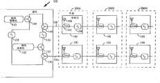
图2是一例基本双元分布式天线系统和基站接口的方框图;Figure 2 is a block diagram of an example of a basic dual-element distributed antenna system and base station interface;
图3是一例可取代图2所给实例的基本E结构元分布式天线系统;Fig. 3 is an example that can replace the basic E structural element distributed antenna system of the example given in Fig. 2;
图4是一远端或移动单元无线电收发机实施例的方框图;Figure 4 is a block diagram of an embodiment of a remote or mobile unit radio transceiver;
图5是一例带有可替换基站接口的双元分布式天线系统的方框图;Figure 5 is a block diagram of an example of a dual-element distributed antenna system with a replaceable base station interface;
图6是一例微区基站的方框图;Fig. 6 is the block diagram of an example micro cell base station;
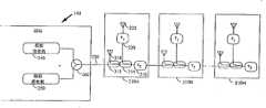
图7是采用有源结构的双元分布式天线系统的方框图;7 is a block diagram of a dual-element distributed antenna system using an active structure;
图8是另一种采用有源结构的双元分布式天线系统的方框图;FIG. 8 is a block diagram of another dual-element distributed antenna system adopting an active structure;
图9是一例由三个并行天线阵列组成的双元分布式天线系统方框图;Fig. 9 is a block diagram of a dual-element distributed antenna system composed of three parallel antenna arrays;
图10是一例含有多个并行阵列的双元分布式天线系统的配置方框图;Fig. 10 is a configuration block diagram of a dual-element distributed antenna system containing multiple parallel arrays;
图11是含有两个并行天线阵列、并含有具有多个独立接收机的基站的双元分布式天线系统方框图。Figure 11 is a block diagram of a dual-element distributed antenna system with two parallel antenna arrays and a base station with multiple independent receivers.
最佳实施例的详细描述Detailed description of the preferred embodiment
单独一组天线和延迟元件提供了一种最基本的分布式天线功能的实施方式。单独一组天线的详细描述见上述美国专利申请号为07/849,651的专利文献中所公开的内容。然而,采用单独一组天线的系统,其服务质量下降,而采用双组天线能减缓服务质量的下降。为了获取高容量,CDMA系统采用一种严格的功率控制机构。每一移动单元发射足够的功率,用来与天线进行联系,并且具有通往该移动单元的最低路径损耗。而与其他天线之间的联系则其能量低于最佳能量值。A single set of antennas and delay elements provides the most basic implementation of distributed antenna functionality. A detailed description of a single set of antennas is disclosed in the aforementioned US Patent Application Serial No. 07/849,651. However, the system using a single set of antennas degrades the quality of service, while the use of dual antennas can slow down the degradation of service quality. To achieve high capacity, CDMA systems employ a strict power control mechanism. Each mobile unit transmits sufficient power to communicate with the antenna and has the lowest path loss to that mobile unit. The energy of the connection with other antennas is lower than the optimal energy value.
如果移动单元的位置非常接近第一天线,并且与其他天线的距离甚远,则多径衰落的结果会使服务受到瞬时破坏。在这种情况下,该移动单元发送的与第一天线联系的功率足够大,但发送不足与远处天线进行可靠联系的功率。如果在这种情况下,该移动单元相对于第一天线突然经受了一个严重的多径衰落,则第一天线处降低了的信号电平和远处天线处的低信号电平会使服务劣化。基站和移动单元之间的通信联系将低于最佳水平,直至功率控制环路增加来自移动单元的发射功率或者移动单元的移动使多径衰落得到缓解为止。If the mobile unit is located very close to the first antenna, and at great distances from the other antennas, the service is momentarily disrupted as a result of multipath fading. In this case, the mobile unit transmits enough power to make contact with the first antenna, but not enough power to make reliable contact with the distant antenna. If in this case the mobile unit experiences a sudden severe multipath fading with respect to the first antenna, the reduced signal level at the first antenna and the low signal level at the distant antenna will degrade the service. The communication link between the base station and the mobile unit will be less than optimal until the power control loop increases the transmit power from the mobile unit or the movement of the mobile unit causes multipath fading to be mitigated.
上述产生的次最佳工作状态可以通过在每一节点处放置两副天线来缓解。因此,与均匀分布单天线的情况相反,移动单元对两副天线距离近似相等,因而配对天线之间的路径损耗也近似相等。如果移动单元的位置与一对配对天线非常接近,与其他天线相距甚远,并且该移动单元突然相对一配对天线经受了一次严重的多径衰落,则第二配对天线应当具有与该移动单元保持通信联系而不致受损的足够的信号电平。The above-mentioned sub-optimal working conditions can be alleviated by placing two antennas at each node. Thus, contrary to the case of uniformly distributed single antennas, the mobile unit is approximately equidistant from both antennas, and thus the path loss between paired antennas is also approximately equal. If the mobile unit is located very close to a paired antenna and far from the other antennas, and the mobile unit suddenly experiences a severe multipath fading relative to one paired antenna, the second paired antenna should have Sufficient signal level at which the communication link is not impaired.
为了从本发明得到最大效果,配对天线的衰落应当具有独立性,即,同一移动单元处两副天线都发生严重衰落的几率很小。为了获得独立的多径衰落,要求配置天线之间具有一定程度的分集接收。To get the maximum benefit from the invention, the fading of the paired antennas should be independent, ie, the chances of both antennas at the same mobile unit experiencing severe fading are small. In order to obtain independent multipath fading, a certain degree of diversity reception between antennas is required.
获得配对天线中相异性的一种途径是将天线隔开一定距离放置。其间距应当使两副天线大体具有相同的作用范围,其隔开的距离足以给出独立的衰落。将两副天线放置在一个基地站来获取分集在宏蜂窝区系统中是较常见的,在宏蜂窝系统中,将具有较大覆盖区(通常为几英里的数量级)的两副天线置于一个基地站处。通常使天线相距10至20个波长(在用于蜂窝区通信的最常用频率下约为6至12英尺),来获取路径分集及因此而产生的衰落独立性。One way to obtain dissimilarity in paired antennas is to place the antennas some distance apart. They should be spaced so that the two antennas have approximately the same range, sufficiently separated to give independent fading. Placing two antennas in one base station to achieve diversity is more common in macrocellular systems where two antennas with larger coverage areas (usually on the order of several miles) are placed in one at the base station. The antennas are typically spaced 10 to 20 wavelengths apart (approximately 6 to 12 feet at the most common frequencies used for cellular communications) to achieve path diversity and thus independence from fading.
获取配对天线分集的第二种方法是使一组配对天线中的每一副天线具有不同的极化,例如垂直极化和水平极化。标准的室内环境必定是三维空间。三维结构中的移动单元具有通向或者来自某一固定天线的各种信号路径,涉及从该三维结构的各表面的多种反射。根据所涉及的角度而定,信号的每一反射可以使反射信号的极化方向旋转。所以,从同一组表面反射的两个极化方向不同的信号形成具有不同相位特性的两个信号路径。因为信号具有不同的相位特性,所以其衰落特性也是不相同的。由于这一过程,使得即使在天线相互间距离很近的情况下,两种不同极化方向的两副配置天线也具有很高程度的独立性。A second way to achieve paired antenna diversity is to have each antenna in a set of paired antennas have a different polarization, such as vertical and horizontal polarization. The standard indoor environment must be a three-dimensional space. A mobile unit in a three-dimensional structure has various signal paths to or from a fixed antenna involving various reflections from surfaces of the three-dimensional structure. Depending on the angle involved, each reflection of the signal may rotate the polarization direction of the reflected signal. Therefore, two signals with different polarization directions reflected from the same set of surfaces form two signal paths with different phase characteristics. Since the signals have different phase characteristics, their fading characteristics are also different. Due to this process, two antennas configured with two different polarization directions have a high degree of independence even when the antennas are located very close to each other.
图1给出了一例按照本发明而构筑的双元天线的天线方向图。正如图1中所描述的那样,这种天线方向图是两个系列的全向天线产生的。每一组天线(30和35)给出一组天线方向图(40A-40J),并且最好相邻天线的方向图重叠。例如,天线30A和35A给出方向图40A。相邻天线指的是具有重叠式邻接方向图的天线,相邻天线不是共同配置于同一节点处的天线。方向图的重叠使所需区域具有连续的天线覆盖。本例中,两组天线分别串联耦接在一起。第一组天线的耦接用线10表示。第二组天线的耦接用线20表示。第二组天线近似第一组天线并行,从而第一组天线中的每一副天线与第二组天线中的一副天线配对。Fig. 1 shows an antenna pattern of an example of a dual-element antenna constructed according to the present invention. As depicted in Figure 1, this antenna pattern is produced by two series of omnidirectional antennas. Each set of antennas (30 and 35) gives a set of antenna patterns (40A-40J), and preferably the patterns of adjacent antennas overlap. For example,
正如前文提及的那样,信号功率的控制是CDMA电话系统实现高用户容量的重量方面。一副普通的全向天线其辐射的信号沿各方向大致相等。其信号强度按照实际环境的传播特性,随对该天线的径向距离增大而减弱。传播特性以移动单元与固定天线之间径向距离的负二次方至负5.5次方的规律变化。As mentioned earlier, signal power control is an important aspect of CDMA telephony systems to achieve high user capacity. An ordinary omnidirectional antenna radiates approximately equal signals in all directions. Its signal strength decreases with the increase of the radial distance to the antenna according to the propagation characteristics of the actual environment. The propagation characteristics vary from the negative quadratic power to the negative 5.5 power of the radial distance between the mobile unit and the fixed antenna.
设计为某一半径范围服务的基地站必须以足够的功率电平进行发射,从而位于基地站覆盖的蜂窝区边缘处的移动单元能够收到足够的信号功率电平。越是靠近蜂窝区中心的移动单元接收的信号电平越是大。可以用现有技术中熟知的多种技术来形成定向天线射束。然而,定向天线射束的形成并不能使传播规律改变。可以通过综合考虑天线方向图、天线位置以及发射机功率来获得信号所要求的覆盖范围。A base station designed to serve a certain radius must transmit at a sufficient power level so that mobile units located at the edge of the cell covered by the base station receive a sufficient signal power level. Mobile units closer to the center of the cell receive higher signal levels. Directional antenna beams can be formed using a variety of techniques well known in the art. However, the formation of directional antenna beams does not change the propagation laws. The coverage required by the signal can be obtained by comprehensively considering the antenna pattern, antenna position, and transmitter power.
分布式天线系统的使用提供了所要求的天线方向图,例如对某一建筑物过道的覆盖,其中每一天线元提供有限的覆盖范围。在提供有限覆盖范围时,接通较小覆盖范围内某一移动单元所需的功率因为传播损耗的降低而相应减小。The use of a distributed antenna system provides the required antenna pattern, eg, coverage of a building aisle, where each antenna element provides limited coverage. When providing limited coverage, the power required to switch on a mobile unit within the smaller coverage area is reduced due to the reduced propagation loss.
然而,当多副天线全部辐射同一信号时将产生问题。即可能存在某些区域,特别是在对两副或两副以上天线等距离的点附近,从两副天线接收的信号会互相抵消。信号会相互抵消的点之间的距离近似为半个波长。在850MHz的频率下,这一间距等于17.6cm或约7英寸。如果两个信号到达接收天线时其强度相等但相位相反,则二信号会相互抵消。基本上这是一种人为的多径衰落。和自然多径衰落的情况相同,分集是减缓衰落的最好方法。CDMA系统设计提供了几种用于减缓多径衰落的分集方法。However, problems arise when multiple antennas are all radiating the same signal. That is, there may be areas, especially near points equidistant from two or more antennas, where the signals received from the two antennas cancel each other out. The distance between the points where the signals cancel each other is approximately half a wavelength. At a frequency of 850 MHz, this spacing equals 17.6 cm or about 7 inches. If two signals arrive at the receiving antenna with equal strength but opposite phases, the two signals will cancel each other out. Basically this is an artificial multipath fading. As in the case of natural multipath fading, diversity is the best way to mitigate fading. The CDMA system design provides several diversity methods for mitigating multipath fading.
上述专利和共同待批的专利申请公开了一种蜂窝区电话系统,这种电话系统采用的CDMA调制具有1.25MHz带宽、多种分集方式以及非常精细的发射机功率控制。利用分集的一种方法是提供瑞克接收机(分离多径接收机)结构,这种结构中具有多个接收机,每一接收机能够接收已经传播了不同路径因而具有不同延迟时间的信号。其中有一个分立的搜寻接收机,这一接收机连续扫描时间域,寻找最佳路径,并相应指派多个数据接收机。The aforementioned patent and co-pending patent application disclose a cellular telephone system using CDMA modulation with a 1.25 MHz bandwidth, multiple diversity modes, and very fine transmitter power control. One way to take advantage of diversity is to provide a rake receiver (rake receiver) architecture in which there are multiple receivers, each capable of receiving a signal that has traveled a different path and thus has a different delay time. There is a discrete search receiver that continuously scans the time domain for the best path and assigns multiple data receivers accordingly.
另一种分集方法是路径分集。在路径分集中,信号从多个天线辐射出去,从而具有一个以上的传播路径。如果两副或两副以上的天线能够提供可接受的通往移动单元接收机的通信路径,那么可以通过路径分集来减弱衰落。Another diversity method is path diversity. In path diversity, the signal radiates from multiple antennas, thus having more than one propagation path. If two or more antennas provide an acceptable communication path to the mobile unit's receiver, path diversity can be used to mitigate fading.
在微蜂窝区系统中,要求有多副天线,以便在所希望的覆盖区提供覆盖,但是系统所需要的容量并不要求每一天线像普通蜂窝区系统中的情况那样都配备一组独立的信号。相反,为了将系统的成本和复杂性减到最小,要求向该微蜂窝区系统中的部分或全部天线馈送相同的射频信号。In a microcellular system, multiple antennas are required to provide coverage in the desired coverage area, but the required capacity of the system does not require each antenna to be equipped with a separate set of Signal. Instead, it is desirable to feed some or all of the antennas in the microcell system with the same radio frequency signal in order to minimize system cost and complexity.
在两副或两副以上的天线都可能存在良好路径的微蜂窝区系统的各服务区内,可以获得路径分集。Path diversity can be obtained in the service areas of a microcell system where two or more antennas may have good paths.
人们所希望的是在不显著增加系统复杂性的情况下,简便且低成本的不同天线馈入信号鉴别方法。这样做的方法在本发明中是在基站收发机和天线阵列中天线元件之间的馈线上加入延迟元件。What is desired is a simple and low-cost method for discriminating signals fed by different antennas without significantly increasing system complexity. This is done in the present invention by adding a delay element to the feeder between the base station transceiver and the antenna elements in the antenna array.
图2描述了一种采用带延迟元件的双套天线的实施例。基站100将信号提供给含有节点200A-200N的天线阵列,并且也从这些天线阵列接收信号。模拟发射机120产生供分布式天线阵列发送的射频信号。该信号由分裂器160分裂成两个要由平行路径发送的信号。第一发送路径由延迟元件150延迟,并由可用双工器取代的合并器140耦合到第一接收路径。第二发送路径由也可用双工器取代的合并器170直接耦合到第二接收路径。合并器180对两个接收路径取和,其中一个路径已由延迟元件155延迟,然后模拟接收机110接收合并的入向射频信号供处理。Figure 2 depicts an embodiment using a dual set of antennas with delay elements.
合并的收、发信号通过分布电缆130和132传送到含有两个分布元190的第一节点200A。每一元件190含有一耦合器192,用来耦合天线196和分布电缆130和132之间的一部分信号。每一分布元190还含有延迟元件,用来对信号进行延迟,并提供与分布电缆130或132上的其他天线元的分集。延迟元件150提供同一节点处配对天线的信号分集。延迟元件194提供与相邻天线的信号时间分集。为了保持与每一相邻天线的完全时间分集,延迟元件194的延迟时间应当与延迟元件150的延迟时间不同。例如,延迟元件150和194之间的延迟时间关系是使系统中基站和每一天线之间的延迟至少相差1筹元时长。时延之差可以通过选择使元件150的时延大于单一路径中的时延总和(例如,元件150的时延是元件194的时延的N倍)来获得。也可以通过选择使元件150的时延是元件194的一个恰当约数来获得(例如,元件150的时延等于1筹元时长,元件194的时延是2筹元时长)。含有相似分布的第二节点200B与第一节点200A串接在一起。天线组这种方法继续连接以达到双套天线的长度。The combined receive and transmit signals are transmitted via
图2的另一种实施例如图3中所描述的那样。图3具有一种E结构,其功能与图2中的平行结构的功能相同。在基站102内,模拟发射机240和模拟接收机250由合并器260耦合到分布电缆230。E结构中的每一节点含有对分布电缆230和天线218之间的信号进行耦合的第一耦合器212。第二耦合器214通过延迟元件220耦合分布电缆230和第二天线222之间的信号。延迟元件220用来提供天线218和222之间在节点210A处的时间分集。第二延迟元件216串联在电缆230的位置上,并提供节点之间(例如节点210A和210B之间)的分集。组件212-222可以在第一节点内以不同的方式重新排列,来完成相同的基本功能。Another embodiment of FIG. 2 is as described in FIG. 3 . FIG. 3 has an E structure whose function is the same as that of the parallel structure in FIG. 2 . Within
如果上述多个天线系统在馈线中配备延迟线,从而来自每一天线的信号至少比其相邻天线延迟了1筹元时长,则移动单元的多个接收机结构使得来自每一天线的信号可以分开接收,并且相关组合的方式不会发生抵消现象。事实上,由于提供了一种路径分集,所以可以通过已经公开的技术极大减弱由于环境中其他反射而产生的衰落。If the multiple antenna system described above is equipped with a delay line in the feedline so that the signal from each antenna is delayed by at least 1 chip time compared to its adjacent antenna, then the multiple receiver configuration of the mobile unit is such that the signal from each antenna can Received separately and in a related combination way no cancellation will occur. In fact, since a path diversity is provided, fading due to other reflections in the environment can be greatly attenuated by the disclosed technique.
移动单元含有一个或一个以上的数据接收机和一个搜寻接收机。该搜寻接收机扫描时间域,判定存在什么路径,并且哪一条路径是最强路径。然后,已有的数据接收机被指派用来解调通过最强路径传播的信号。基站接收机含有类似的性能。Mobile units contain one or more data receivers and a search receiver. The search receiver scans the time domain to determine what paths exist and which path is the strongest. Existing data receivers are then assigned to demodulate the signal propagating through the strongest path. Base station receivers contain similar capabilities.
图4以方框图的形式描绘了一例移动单元CDMA电话机。该移动单元包括一天线300,该天线300通过双工器302与模拟接收机304和发射功率放大器306耦合。Figure 4 depicts an example mobile unit CDMA telephone in block diagram form. The mobile unit includes an
接收机304接收来自双工器的射频信号,进行放大和下变频。这些信号再经过滤波和数字化处理后,提供给数字数据接收机310A-310N以及搜寻接收机314。接收机304、310A-310N以及314的典型实施例的更详细描述见上述美国专利5,103,459和5,109,390中的描述。The
接收机304还有功率控制功能,用来调整移动单元的发射功率。接收机304产生提供给发射功率控制电路308的模拟功率控制信号。
模拟接收机304输出处的数字化信号可以含有许多正在进行呼叫的信号,以及由当前基站和所有相邻基站传送的导频(pilot carri-ers)。接收机310A-310N的功能是使抽样值与恰当的PN序列相关。这种相关处理过程提供了一种本领域中人们所熟悉的“处理增益”,这一性能使与恰当PN序列适配的信号的信扰比得到提高,其他信号的信扰比则不提高。随后用从最接近的基站得到的导频作为载频相位基准,同步地检测出相关输出。这一检测处理的结果是一种编码数据码元序列。The digitized signal at the output of the
本发明中所使用的PN序列的特性是对多路径信号提供鉴别。当信号在通过一条以上路径(或者在本发明中通过一副以上天线)以后到达移动接收机时,信号的接收时间存在差异。如果这一时间差超过1筹元时长,则相关处理在信号之间作出鉴别。数据接收机能够跟踪并且解调早到信号或者晚到信号。如果配置了两个或两个以上数据接收机(通常为三个),则可以并行跟踪并处理多条独立路径。The nature of the PN sequence used in the present invention is to provide discrimination for multipath signals. When a signal arrives at a mobile receiver after traveling through more than one path (or, in the present invention, more than one pair of antennas), there is a difference in the reception time of the signal. If this time difference exceeds 1 chip duration, then the correlation process differentiates between the signals. The data receiver is able to track and demodulate early or late signals. If two or more data receivers (typically three) are configured, multiple independent paths can be tracked and processed in parallel.
在控制处理器316的控制下,搜寻接收机314用来在基站接收到导频信号的标称时刻附近,对时间域连续进行扫描,以搜寻其他多径导频信号。在标称时刻以外的其他时刻,接收机314测量所要波形的任意一次接收的强度。接收机314比较接收信号中的信号强度,把一信号强度信号提供给指示最强信号的控制处理器316。处理器316将控制信号提供给数据接收机310A-310N,用于每一个数据接收机对不同的最强信号进行处理。Under the control of the
接收机310A-310N的输出提供给分集合并器和译码电路318。电路318内的分集合并器电路调整二接收码元流的时间使其对齐,并将它们加在一起。叠加处理以后,再用与二接收码元流相对信号强度对应的一个数来乘该二接收码元流。这一操作可以视为一个最大比值分集合并器。产生的合并信号流随后再用同样也包含在电路318内的前向纠错(FEC)译码器进行译码。常用的数字基带设备是一种数字声码器系统。这种CDMA系统设计成适应各种不同的声码器。The outputs of
基带电路320通常包括一数字声码器(未图示),其可以是可变速率型。基带电路320还用作与电话机或其他类型外围装置的接口。基带电路320按照电路318提供的信息,将输出信息信号提供给用户。
在移动单元至基站的链路(反向链路)中,用户模拟声音信号通常是通过一手机、作为基带电路320的输入来提供的。基带电路320包括一个将模拟信号转换成数字信号的模数(A/D)转换器(未图示)。该数字信号提供给数字声码器,进行编码。该声码器的输出提供至一前向纠错(FEC)编码电路(未示出)。本典型实施例中,纠错编码采用的是一种卷积编码方案。数字化编码信号从基带电路320输出至发射调制器322。In the mobile unit to base station link (reverse link), the user's analog voice signal is usually provided as an input to the
发射调制器322对发射数据进行编码,本典型实施例中,这是一种基于沃尔什(Walsh)码的64进制正交信令技术,发射调制器322随后在PN载波信号上调制已编码信号,PN载波信号的PN序列在所有移动单元中是通用的,但是赋予用于呼叫的移动站的编码相位偏差是不同的。另一种情况是,可以按照赋给那一呼叫的地址函数来选择PN序列。PN序列根据呼叫建立信息,由控制处理器316来判定,而呼叫建立信息由基站来传送,并由接收机310A-310N以及控制处理器316来解码。控制处理器316将PN序列信息提供给发射调制器322以及接收机310A-310N,进行呼叫译码。更详细地说,可以根据PN扩展信号来使用一外PN码。数据调制的详细论述见美国专利5,103,459中所公开的内容。Transmit
发射调制器322进一步将调制信号转换成模拟信号,用来调制在一中频(IF)载波信号上。从发射调制器322产生的IF信号输出被提供至发射功率控制电路308。电路308中,发射信号功率是由接收机304提供的模拟功率控制信号来控制的。微区基站以功率调整指令的形式发送的控制位由数据接收机310A-310N进行处理,并提供给控制处理器316。这些功率调整指令被控制处理器316用来设定移动单元发射时的功率电平。响应于这些指令,控制处理器316产生提供给电路308的数字功率控制信号。接收机310A-310N和314、控制处理器316和发射功率控制308之间关于功率控制的关系的进一步论述见上述美国专利5,056,109中的描述。The transmit
发射功率控制电路308将功率控制已调信号输出至发射功率放大器电路306。电路306对IF信号进行放大,并将该IF信号的频率转换成射频。频率电路306包括一放大器,该放大器将功率放大至一最终输出电平。要发射的信号从电路306输出至双工器302。该双工器302将信号耦合至天线300,用来发射至微区基站。The transmit
基站结构与图4的移动单元结构相似。下面描述的基站最佳实施例包含相应于图5中的组成部分,图5描述了另一种图2所示结构的基站结构实施例。图5中,由基站通过每一平行路径接收的移动单元信号并不在射频时合并为射频,而是在基站中被分开接收和解调,并按照数字位相关合并。二返回路径的分开解调有若干优点,包括由相关合并带来的信扰比增大和功率控制中波动较小,这两点又使移动站对基站的链路具有高容量。The structure of the base station is similar to that of the mobile unit in FIG. 4 . The preferred embodiment of the base station described below includes components corresponding to those shown in FIG. 5 . FIG. 5 describes another embodiment of the structure of the base station shown in FIG. 2 . In Figure 5, the mobile unit signals received by the base station via each parallel path are not combined at radio frequency into radio frequency, but are received and demodulated separately in the base station, and combined according to digital bit correlation. The separate demodulation of the two return paths has several advantages, including increased signal-to-interference ratio due to correlation combining and less fluctuation in power control, both of which in turn allow high capacity mobile station to base station links.
图5中,节点和分布元与图2中的相应组成部分相同。基站100′具有如图5所示的经修正的射频结构。附加模拟接收机115的作用独立于模拟接收机110,各连接不同的解调器,见图6中的描述。图2中的合并器180和延迟元件155已被去掉。因为这一特定实施例中已不再需这些元件。In Figure 5, the nodes and distribution elements are the same as the corresponding components in Figure 2. The base station 100' has a modified radio frequency structure as shown in FIG. 5 . The role of the
图6以方框图的形式描述了微区基站的典型实施例。图6中,接收机系统由模拟接收机110组成,还可以含有模拟接收机115,并与图2和图5中的相同组成部分对应。接收机系统进一步由与接收机110关联的独立搜寻接收机500和数字数据接收机510A-510N、与模拟接收机115关联的独立搜寻接收机515和数字数据接收机520A-520N,以及分集合并器和译码器电路530组成。应该指出的是,对于图2所示的天线,基站不需要包括搜寻接收机515、数字数据接收机520A-520N以及模拟接收机115。接收机系统还可以包括与每一模拟接收机110和115关联的任意个数的数字数据接收机。应该理解的是,也可以只采用一个与每一模拟接收机关联的数字数据接收机(例如,数据接收机510A)。然而,为了获取瑞克接收机功能性的全部优点,最好每一天线系统采用两个或更多个数据接收机,例如,通常采用三个或四个。一典型实施例的进一步细节见美国专利5,103,459以及5,109,390。Figure 6 depicts an exemplary embodiment of a microcell base station in block diagram form. In FIG. 6, the receiver system is composed of an
正如图5中所描述的那样,模拟接收机110和115分别输出一数字型的混合信号,该混合信号是从一个或更多个移动单元的发射中产生的。搜寻接收机500和515,每一个跟踪各移动单元发射的多径传播。数据接收机510A-510N以及520A-520N中的每一个被指派对调制数据信号的某一特定多径传播进行解调,获取编码信息数据。从模拟接收机110和115得到的合并信号输出也被提供至其他组搜寻接收机和相应的数据接收机(未图示),这些接收机的结构与用来对其他移动单元发射的信号进行跟踪和解调的搜寻接收机550和515以及数据接收机510A-510N和520A-520N的结构相同。As depicted in FIG. 5,
图6所示微区基站包括CDMA控制器540,该CDMA控制器540与数据接收机510A-510N和520A-520N以及搜寻接收机500和515耦合。CDMA控制器540给出沃尔什序列以及编码分配、信号处理、定时信号产生、功率控制以及各种其他有关的功能。The microcell base station shown in FIG. 6 includes a
天线组中一个天线上所接收的信号被提供给模拟接收机110,随后再提供给搜寻接收机500。搜寻接收机500用来扫描有关接收信号的时域,确保数字数据接收机510A-510N对与某一特定移动单元关联的最强时域信号进行跟踪和处理。搜寻接收机500将相应的信号提供给CDMA控制器540,该CDMA控制器540响应于此信号,产生控制信号,并将这些控制信号提供给数字数据接收机510A-510N,用来选择用作处理的恰当的接收信号。The signal received on one antenna of the antenna group is provided to the
分布式天线组中第二副天线上接收的信号如果被采用的话,则被提供至模拟接收机115,并随后被提供至搜寻接收机520A-520N。搜导接收机515也被用来扫描有关接收信号的时域,确保数字数据接收机520A-520N对与某一特定移动单元关联的最强时域信号进行跟踪和处理。搜寻接收机515将相应的信号提供给CDMA控制器540,该CDMA控制器540响应于这些信号,产生控制信号,并把这些控制信号提供给数字数据接收机520A-520N,用来选择用作处理的恰当接收信号。随后,从接收机510A-510N和520A-520N得到的输出信号由分集合并器和译码器530处理成最佳性能。The signal received on the second antenna in the distributed antenna group, if employed, is provided to
基站数据接收机和搜寻接收机中的信号处理与由移动单元中相似元件进行的信号处理在几个方面是不相同的。在不同于基站至移动单元链路(前向链路)的移动单元至基站链路(反向链路)中,移动单元不发射可以用作基站信号处理中相关基准的导频信号。移动单元至基站链路的特征是采用64进制正交信令进行的非相关调制和解调方法。The signal processing in the base station data receiver and search receiver differs in several respects from the signal processing performed by similar elements in the mobile unit. In the mobile unit to base station link (reverse link), which differs from the base station to mobile unit link (forward link), the mobile unit does not transmit a pilot signal which can be used as a relative reference in signal processing by the base station. The mobile unit to base station link is characterized by a non-correlated modulation and demodulation method using 64 quadrature signaling.
再回到图6,搜寻接收机500和数字数据接收机510A-510N接收模拟接收机110产生的混合信号输出。为了对传送至与一移动单元通信的特定基站的扩谱信号进行译码,必须产生恰当的PN序列。产生移动单元信号的进一步细节见美国专利5,103,459。Returning again to FIG. 6,
每一数据接收机跟踪正被接收的信号的时序。这是通过一种熟知的技术,即,使接收信号与略早的本地参考PN相关联以及使接收信号与一略迟的本地参考PN相关联来实现的。如果不存在时序误差,则这两种相关之间的差平均为零。相反,如果存在时序误差,则此差将给出误差的大小和符号,从而对接收机的时间作相应的调整。Each data receiver tracks the timing of the signal being received. This is accomplished by a well-known technique of correlating the received signal with a slightly earlier local reference PN and correlating the received signal with a slightly later local reference PN. If there were no timing errors, the difference between these two correlations would be zero on average. Conversely, if there is a timing error, the difference will give the magnitude and sign of the error, and the receiver's time will be adjusted accordingly.
在CDMA控制器540的控制下,外部网或内部网(例如专用小交换机PBX)产生的信号被耦合至恰当的发射调制器的声码器555。在CDMA控制器540控制下的发射调制器535对要发射到接收移动单元的数据进行扩谱调制。发射调制器535被指派对要发送至特定移动单元的数据进行编码和调制,对该特定移动单元来说,配置有搜寻接收机500和515,以及数据接收机510A-510N和520A-520N。发射调制器535用选自与该信号有关的一组正交码的一个正交码,对声码器数据进行调制,随后用一PN扩展码进行调制。该PN扩展信号随后被转换成模拟形式,并被提供至发射功率控制电路550。Under the control of the
在CDMA控制器540的控制下,发射功率控制电路550控制该信号的传输功率。电路550的输出被提供至加法器560,与其他信道单元的发射调制器/发射功率控制电路的输出加在一起。加法器560的输出被提供至模拟发射机120。模拟发射机120对该信号进行放大,用来通过分布式天线而输出,辐射至基站服务范围内的移动单元。图6所示典型发射机电路的进一步细节见美国专利5,103,459。Under the control of
图6进一步描述了导频/控制信道发生器和发射功率控制电路545。电路545在CDMA控制器540的控制下,产生并控制用来耦合至模拟发射机120的导频信号、同步信道和播叫信道的功率。Figure 6 further describes the pilot/control channel generator and transmit
很明显,在分布式天线的前述实施例中,大多数信号处理,包括频率转换、放大及滤波是由该基站内的模拟接收机和模拟发射电路来进行的。然而,通过给出一有源天线元,将这些功能转移到每一节点处的天线元具有许多优点。Obviously, in the foregoing embodiments of the distributed antenna, most signal processing, including frequency conversion, amplification and filtering, is performed by the analog receiver and analog transmit circuits within the base station. However, by giving an active antenna element, there are many advantages to shifting these functions to the antenna elements at each node.
图7描述了一例有源天线元的实施例。基站600含有模拟接收机605和635,模拟接收机605和635在一中频(IF)下,接收来自分布式天线阵列或节点720A-720N的信号,节点720A-720N中的每一个由一对有源天线元705组成。本特定结构中,模拟接收机605沿分布式电缆720接收来自第一组有源天线元705的信号,而模拟接收机635沿分布式电缆725接收来自第二组有源天线元705的信号。模拟发射机625产生的IF频率下的信号被分裂器630分成两个由并行路径传送的信号。延迟元件620对分布式电缆722上提供的发射IF信号进行延迟,该分布式电缆722用来连接节点720A-720N中所含有源天线元组705中第一个有源天线元组。来自分裂器630的相应非延迟发射IF信号由是用作节点720A-720N中第二个有源天线元705的分布式电缆722上给出的。Figure 7 depicts an embodiment of an active antenna element. Base station 600 contains analog receivers 605 and 635 that receive signals at an intermediate frequency (IF) from distributed antenna arrays or nodes 720A-720N, each of nodes 720A-720N consisting of a pair of source antenna element 705. In this particular configuration, analog receiver 605 receives signals from first group of active antenna elements 705 along distribution cable 720 and analog receiver 635 receives signals from second group of active antenna elements 705 along distribution cable 725 . The signal at the IF frequency generated by the analog transmitter 625 is split by a splitter 630 into two signals transmitted by parallel paths. Delay element 620 delays the transmit IF signal provided on distribution cable 722 used to connect the first active antenna tuple 705 contained in nodes 720A-720N. The corresponding non-delayed transmit IF signal from splitter 630 is presented by distribution cable 722 which is used as second active antenna element 705 in nodes 720A-720N.
有源天线元705需要直流电源和频率参考信号。这些信号可以为节点内的一个有源天线元产生,也可以为一对有源天线元产生。提供这些信号的最好方法是将这些信号叠加到分布式电缆720、722、725以及727的IF信号上。参考频率源610和612分别产生一参考频率信号,该参考频率信号用于相应天线元中的锁相环路。参考频率信号最好位于不同的频段,而不是所接收IF信号,以方便基站和天线元处的滤波。在本典型实施例中,加法器640和642叠加用于电缆720和725上传输的参考频率信号。同样,电源615和617通过加法器645和647以及电缆722和727,提供用于有源天线元的直流电源。应该理解的是,按照各天线元705的连接方式,参考频率信号和直流电源可以在发射分布式电缆或接收分布式电缆或者其他各种装置上提供。The active antenna element 705 requires a DC power supply and a frequency reference signal. These signals can be generated for one active antenna element within a node, or for a pair of active antenna elements. The best way to provide these signals is to superimpose them on the IF signals of distribution cables 720, 722, 725 and 727. Reference frequency sources 610 and 612 each generate a reference frequency signal that is used in a phase locked loop in a corresponding antenna element. The reference frequency signal is preferably in a different frequency band than the received IF signal to facilitate filtering at the base station and antenna elements. In the exemplary embodiment, summers 640 and 642 add reference frequency signals for transmission on cables 720 and 725 . Likewise, power supplies 615 and 617 provide DC power for the active antenna elements through summers 645 and 647 and cables 722 and 727 . It should be understood that, according to the connection mode of each antenna element 705, the reference frequency signal and DC power can be provided on the transmitting distribution cable or the receiving distribution cable or other various devices.
分布式天线的每一节点含有两个有源天线元705。因为除了天线元705所连接的电缆有所不同的以外,所有的天线元705均相同,所以只需讨论与一对分布式电缆相连接的单个天线元705之功能就可以了。天线元705接收电缆722上的IF发射信号,并通过在相邻天线之间提供时间分集的延迟元件650与之耦合。IF发射信号的一部分是通过耦合器655从主路经耦合的。被耦合的信号由混频器690作上变频,以便在恰当射频下发射。该信号通过双工器695耦合至天线700。Each node of the distributed antenna contains two active antenna elements 705 . Since all antenna elements 705 are identical except for the cables to which they are connected, only the function of a single antenna element 705 connected to a pair of distributed cables will be discussed. Antenna element 705 receives the IF transmit signal on cable 722 and couples thereto via delay element 650 that provides time diversity between adjacent antennas. A portion of the IF transmit signal is coupled from the main path through coupler 655 . The coupled signal is upconverted by mixer 690 for transmission at the proper radio frequency. The signal is coupled to antenna 700 through duplexer 695 .
天线700还接收移动单元发射的信号,并通过双工器695将该信号耦合至天线元的接收部分。接收信号由混频器675下变频至一IF信号,并由耦合器660耦合至电缆720。耦合器660在电缆720上耦合的信号与由延迟元件665延迟的其他节点天线元所接收的信号合并。出于对噪声系数的考虑,天线元的一种实际实施例还可以在接收路径中(例如位于双工器695和混频器675之间)含有增益级。与此相同,发射路径也可以含有增益级,来提高天线处的信号电平。还可以加进一些滤波器,来方便信号处理。The antenna 700 also receives signals transmitted by the mobile unit and couples the signals through the duplexer 695 to the receive portion of the antenna element. The received signal is down-converted to an IF signal by mixer 675 and coupled to cable 720 by coupler 660 . The signal coupled by coupler 660 on cable 720 is combined with the signal received by the other node antenna elements delayed by delay element 665 . A practical embodiment of the antenna element may also include a gain stage in the receive path (eg, between duplexer 695 and mixer 675) for noise figure considerations. Likewise, the transmit path can also contain gain stages to increase the signal level at the antenna. Some filters can also be added to facilitate signal processing.
天线元705的混频器675和690必须由本地振荡器(LO)以一恰当频率来驱动。本实施例中,该LO包含在天线元内。LO680是一锁相环路(PLL),提供用于混频器675的驱动LO,LO685是一锁相环路(PLL),提供用于混频器690的驱动LO。参考频率用来将PLL电路锁在一公共相位上,并由低通滤波器(LPF)670从接收路由接入,低通滤波器670对电缆720上的信号进行低通滤波,提取参考频率信号。同时,直流电源通过电缆722接入(未图示),用于元件内的各种有源功能。另一种频率方案可方便单一LO的使用。The mixers 675 and 690 of the antenna element 705 must be driven at a proper frequency by a local oscillator (LO). In this embodiment, the LO is included in the antenna element. LO 680 is a phase locked loop (PLL) that provides the driving LO for mixer 675 and LO 685 is a phase locked loop (PLL) that provides the driving LO for mixer 690 . The reference frequency is used to lock the PLL circuit on a common phase, and is connected from the receiving route by a low-pass filter (LPF) 670. The low-pass filter 670 performs low-pass filtering on the signal on the cable 720 to extract the reference frequency signal . At the same time, DC power is fed in via cable 722 (not shown) for various active functions within the element. Another frequency scheme facilitates the use of a single LO.
有源天线的优点有许多,而且其硬件简单,成本很低。有源天线元可以采用方便的已有移动单元技术来实施。与射频信号的情况相比,IF信号每英尺电缆的电缆损耗较低,因而减小了所需的放大量。与射频相比,中频下的延迟元件是不贵的。在IF下,延迟元件可以是SAW滤波器,这种滤波器提供的延迟在信号带宽内具有极小的相位误差,并滤去不需要的信号。SAW滤波器串行级联方便,而高频元件需要高度隔离以正确运行。The advantages of an active antenna are many, and its hardware is simple and low cost. Active antenna elements may be implemented using conveniently known mobile unit technology. IF signals have lower cable loss per foot of cable than is the case with RF signals, thereby reducing the amount of amplification required. Delay components at IF are inexpensive compared to RF. At IF, the delay element can be a SAW filter, which provides a delay with minimal phase error within the signal bandwidth and filters out unwanted signals. SAW filters are conveniently cascaded in series, while high frequency components require a high degree of isolation to function properly.
有源天线元的实施也可以无需变频电路。图8描述了另一种分布式天线有源天线元的实施例。图8中,在天线元的发射路径和接收路径中加进了有源放大元件。Active antenna elements can also be implemented without frequency conversion circuits. FIG. 8 depicts another embodiment of an active antenna element of a distributed antenna. In Figure 8, active amplifying elements are added to the transmit path and receive path of the antenna element.
图8中,基站800含有模拟接收机805和835,模拟接收机805和835接收来自分布式天线阵列或节点920A-920N的信号,节点920A-920N中每一个均含有有源天线元905。在这一特定结构中,模拟接收机805沿分布电缆920从第一组有源天线元905接收信号,而模拟接收机835延分布电缆925从第二组有源天线905接收信号。根据发射机825产生一个信号,该信号由分裂器835分裂成两个供平行路径传输的信号。延迟元件820使分布电缆922上提供的发射信号延迟,该电缆用于连接节点920A-920N中所包含的第一组有源天线元905。从分裂器830得到的相应非延迟发射信号通过分布电缆927提供给节点920A-920N中所包含的第二组有源天线元905。In FIG. 8,
同时,有源天线元905也需要工作用的直流电源。正如结合附图8所作的讨论那样,提供信号的一种方法是将其叠加到分布电缆的信号上。电源815提供用作有源天线元的直流电源是通过叠加器845而叠加到电缆922上去的。与此类似,电源817提供用于有源天线元的直流电源是通过迭加器847而叠加到电缆927上去的。At the same time, the
分布式天线的每一节点含有两个有源天线元905。天线元905接收电缆922上的发射信号,并通过提供相邻节点之间时间分集的延迟元件750而与之耦合。一部分发射信号是通过耦合器755从主路径耦合的。被耦合的信号由放大器790放大,以便在恰当电平下传输。该信号通过双工器795而被耦合至天线800。Each node of the distributed antenna contains two
天线800还接收移动单元发射的信号,并通过双工器795,将该信号耦合至天线元的接收部分。所接收的信号由低噪声放大器775放大,并由耦合器760,与已由延迟元件765延迟的其他天线元所接收的信号耦合在一起。天线元在实际使用中,还可以包含滤波器元件,以便于信号处理。直流电源的耦合是通过电缆922来进行的,用于天线元内所进行的各种功能。The
图8所示的有源天线也可以用于含有一分布式天线的室外环境。例如,在高层建筑相距很近的市区内,单个天线基站将不足以在所要求的覆盖范围内提供稳定一致的信号电平。天线阵列可以用来覆盖有问题的区域。在这种情况下,分布式天线的节点位置将相互非常接近,自然的传播路径不会给出多径信号进行单独解调所需的必要延迟时间。本发明的分布式天线是这种情况的理想解决方法。室外环境中节点之间距离的增加,这种增加带的更高发射功率要求以及接收时电缆损耗的增加,均需要使用有源天线元。特别是,图8所示的结构是该系统的实际实施方式。The active antenna shown in Figure 8 can also be used in an outdoor environment with a distributed antenna. For example, in urban areas where tall buildings are in close proximity, a single antenna base station will not be sufficient to provide consistent signal levels within the required coverage area. Antenna arrays can be used to cover problematic areas. In this case, the nodes of the distributed antennas will be located very close to each other, and the natural propagation paths will not give the necessary delay time for separate demodulation of the multipath signals. The distributed antenna of the present invention is an ideal solution to this situation. The increased distance between nodes in an outdoor environment, the higher transmit power requirements associated with this increase, and the increased cable loss when receiving, require the use of active antenna elements. In particular, the structure shown in Figure 8 is a practical implementation of the system.
本发明的典型实施例中,将节点串联耦合在一起形成一阵列。如果出现节点故障或者电缆连接有问题,相对于基站呈串联连接的节点出现故障或问题,则将导致天线系统无法使用。为了克服这一潜在的缺点,节点可以用并联或者串/并联组合的方式耦合在一起,从而在出现节点故障或电缆连接问题时,继续提供电波覆盖。图9中画出一种节点的串/并联组合,图中描述了一种图2所示典型实施例的改进实施例。新元件930、932、934以及936在图2中没有对应元件,在图中画在基站101的外面,然而,如果将这些元件合并在基站内可以起同样的作用。新元件930和934是分裂器,将两个天线阵列耦合到基站101。含有节点200A′-200N′的第一天线阵列接收并提供分布电缆130′和132′上的信号。含有节点200A″-200N″的第二平行天线阵列接收并提供分布电缆130″和132″上的信号,不过该二分布电缆分别加进了延迟元件932和936。最好选择延迟元件932和936的时延值,使系统中的每一天线相对于基站具有不同的延迟。In an exemplary embodiment of the invention, the nodes are coupled together in series to form an array. If there is a node failure or a problem with the cable connection, failure or problem with the node connected in series with respect to the base station will render the antenna system unusable. To overcome this potential shortcoming, nodes can be coupled together in parallel or in series/parallel combinations to continue to provide airwave coverage in the event of a node failure or cable connection problem. A series/parallel combination of nodes is shown in FIG. 9, which depicts a modified embodiment of the exemplary embodiment shown in FIG. 2. The new elements 930, 932, 934 and 936 have no corresponding elements in FIG. 2, and are drawn outside the base station 101 in the figure. However, if these elements are incorporated in the base station, they can play the same role. New elements 930 and 934 are splitters that couple the two antenna arrays to base station 101 . A first antenna
图9中的布局可以取各种不同的形式。图9中的节点和天线元可以被图3、5、7或8中的节点和天线元来取代。分裂器930和934可以将两个以上的阵列耦合至基站。事实上,在典型的并联布局中,系统的每一个节点可以独立地与基站连接在一起。基站布局也可以取各种不同的实施方式。基站101可以变换成含有模拟接收机115,使其布局与图5所示布局相似。The layout in Figure 9 can take a variety of different forms. The nodes and antenna elements in FIG. 9 may be replaced by the nodes and antenna elements in FIGS. 3 , 5 , 7 or 8 . Splitters 930 and 934 can couple more than two arrays to the base station. In fact, in a typical parallel arrangement, each node of the system can be independently connected to the base station. The layout of the base station can also be implemented in various manners. Base station 101 can be converted to include
含有串/并联节点组合的系统中天线的位置可以取各种形式。一种位置布局如图10所示。图10包含一基站和3个并行的串联阵列组。基站940的布局在本例中任意,可以是本文描述的任一基站的简单变化形式。按照本发明,每一天线节点950A-950N、950A′-950N′以及950A″-950N″是一种双元天线节点。天线节点950A-950N含有第一阵列。天线节点950A′-950N′包含第二阵列。天线节点950A″-950N″包含第三节点。理想情况下,图10的每一天线节点相对于基站具有不同的延迟。图10中的天线节点布置说明一种天线分布,这种分布提供了大量的防故障措施。每一阵列的节点与另一阵列的节点错开一个位置,而不是第二阵列与第一阵列对齐,第三阵列与第二阵列对齐。在这种结构中,某一阵列中的故障不一定会使基站覆盖范围内任一点处的业务完全中断。一故障状态产生系统的软故障,降低整个系统的性能,而不会使该地区产生业务中断的现象。The location of the antennas in a system with a combination of series/parallel nodes can take various forms. One location layout is shown in FIG. 10 . Figure 10 contains a base station and three parallel series array groups. The layout of the base stations 940 is arbitrary in this example and could be simple variations of any of the base stations described herein. In accordance with the present invention, each antenna node 950A-950N, 950A'-950N', and 950A"-950N" is a dual antenna node. Antenna nodes 950A-950N contain a first array. Antenna nodes 950A'-950N' include a second array. Antenna nodes 950A"-950N" comprise a third node. Ideally, each antenna node of Fig. 10 has a different delay with respect to the base station. The antenna node arrangement in Figure 10 illustrates an antenna distribution that provides a great deal of protection against failure. The nodes of each array are offset from the nodes of the other array by one position, instead of the second array being aligned with the first array and the third array being aligned with the second array. In this configuration, a failure in one array does not necessarily completely disrupt service at any point within the base station's coverage area. A fault state produces a soft fault of the system, reducing the performance of the entire system without causing service interruption in this area.
对于高容量的区域,节点的并联或串/并组合方式比整个阵列采用简单的串联连接还有一些优点。一CDMA线路受限于能够有效组合在一给定通信信道内的最大独立信号数。如果超过信号的最大数量,则系统容量过载,整个系统质量降低。一旦信号被组合在一起以后,例如在单一节点串联的情况下,就没有办法使能被发射到多个接收机并被单独解调的信号分开。基站的电路需要限制发射到其天线覆盖范围内的移动单元的信号数量。每一由基站发射的信号增加了每一移动单元处的噪声电平,因为该移动单元并不是所发信号的目的地。采用节点的并联或串/并联组合和多个接收机和发射机,可提高单个基站的信号处理能力。For high-capacity areas, parallel or series/parallel combinations of nodes have some advantages over simple series connections of the entire array. A CDMA link is limited by the maximum number of independent signals that can be efficiently combined within a given communication channel. If the maximum number of signals is exceeded, the system capacity is overloaded and the overall system quality is degraded. Once the signals are combined, such as in the case of a single node cascaded, there is no way to separate the signals that can be transmitted to multiple receivers and demodulated individually. The base station's circuitry needs to limit the number of signals transmitted to mobile units within its antenna coverage range. Each signal transmitted by a base station increases the noise level at each mobile unit since the mobile unit is not the destination of the transmitted signal. Using parallel or series/parallel combinations of nodes and multiple receivers and transmitters, the signal processing capability of a single base station can be increased.
为了增加单个基站的系统容量,设计的系统中至少有两个独立阵列。这种情况下,将一独立阵列定为任意组的节点来,其中,每一节点相对于基站具有不同的延迟,并且系统中的每一节点可以仅属于一个阵列。这种方案中,因为两个节点分别属于不同的独立阵列,所以不存在两个节点相对于基站具有相同延迟的缺点。各独立阵列的位置安排得存在仅由一个独立阵列覆盖的区域。馈给每一独立阵列来自某一专用发射机的发射信号,并将一接收信号提供给一专用接受机。当某一移动单元位于仅有一个独立阵列覆盖的范围内时,与不对该移动单元进行通信的阵列对应的发射机会停止向该移动站发射信号,从而减少了对其他移动单元的干扰。与此相同,当某一移动单元位于仅有一个独立阵列的覆盖范围内时,与不对该移动单元进行通信的阵列对应的接收机可以免受该移动单元的干扰。当某一移动单元位于两个独立阵列的覆盖范围内时,两部发射机将相同的信息信号提供给移动单元,但每一发射机采用不同的扩展序列对信息信号进行调制,从而增加了移动单元处接收的总信号,减少了抵消信号相加的机会。与此类似,当某一移动单元位于两个独立阵列的覆盖范围内时,这两个阵列能够独立接收信号,并且随后能合并解调处理过程中从每一路径得到的能量,给出一个提高的总信号电平。(这一处理过程与标准CDMA蜂窝区系统中含有多副扇形天线的基站所采用的处理过程很相似。)注意,图9的布局中含有模拟接收机115,因为接收机115从图中两个并行阵列的每一节点接收一输入,所以不会增加基站101的容量。In order to increase the system capacity of a single base station, there are at least two independent arrays in the designed system. In this case, define an independent array as any set of nodes, where each node has a different delay relative to the base station, and each node in the system can belong to only one array. In this solution, since the two nodes belong to different independent arrays, there is no disadvantage that the two nodes have the same delay relative to the base station. The individual arrays are positioned such that there is an area covered by only one individual array. Each independent array is fed with a transmit signal from a dedicated transmitter and a receive signal is provided to a dedicated receiver. When a mobile unit is within range of only one independent array, the transmitter corresponding to the array not communicating with the mobile unit stops transmitting to the mobile unit, thereby reducing interference to other mobile units. Likewise, when a mobile unit is within the coverage area of only one independent array, receivers corresponding to arrays that do not communicate with the mobile unit can be protected from interference by the mobile unit. When a mobile unit is located within the coverage of two independent arrays, the two transmitters provide the same information signal to the mobile unit, but each transmitter uses a different spreading sequence to modulate the information signal, thus increasing the mobile unit total signal received at the unit, reducing the chance of canceling signal summation. Similarly, when a mobile unit is within the coverage of two independent arrays, the two arrays can receive signals independently and can then combine the energy derived from each path during the demodulation process, giving an improved total signal level. (This process is very similar to the process used by a base station with multiple sectored antennas in a standard CDMA cellular system.) Note that the layout of FIG. Each node of the parallel array receives an input, so the capacity of the base station 101 is not increased.
这一概念的典型实施例见图11所示,其根据是图8所示的结构。含有节点920A′-920N′的第一天线阵列通过电缆927′、叠加器847和分裂器830与模拟发射机825耦合。第一天线阵列通过电缆922′、叠加器845、延迟器820以及分裂器830还与发射机825耦合。含有节点920A″-920N″的第二天线阵列通过电缆927″、叠加器847″以及分裂器830″与模拟发射机825″耦合。第二天线阵列通过电缆922″、加法器845″、延迟器820″以及分裂器830″还与模拟发射机835耦合。A typical embodiment of this concept is shown in FIG. 11 and based on the structure shown in FIG. 8 . A first antenna
采用两组平行天线增加了系统在一般运行期间的优点,减小了多径衰落最坏时产生的影响。基站内各路径的协调组合提高了移动单元至基站的线路上的信噪比。本发明还降低了移动单元的功率控制波动。这两个因素均使容量增大,系统性能提高。分布式天线比起仅仅通过将两个天线均匀地串联在一起具有更多的优点。The use of two sets of parallel antennas increases the advantage of the system during normal operation and reduces the worst-case effects of multipath fading. The coordinated combination of paths within the base station improves the signal-to-noise ratio on the line from the mobile unit to the base station. The invention also reduces power control fluctuations of the mobile unit. Both of these factors result in increased capacity and improved system performance. Distributed antennas have many advantages over just connecting two antennas evenly in series.
很明显,图2、3、5、7、8、9、10和11的实施例可以具有各种变化形式,包括每一组成部分内元件的简单再排列。这些实施例的具体实施还需要功率分配、增益、滤波等其他功能。前述最佳实施例的描述使本领域的任何技术人员能够实施或使用本发明。很明显。本领域的技术人员可以对这些实施例作各种改进,并且无需发明者就能将本文限定的基本原理应用于其他实施例。因此,本发明并非仅限于已述实施例,而在最宽的范围内与已揭示的原理及新特征一致。It will be apparent that the embodiments of Figures 2, 3, 5, 7, 8, 9, 10 and 11 may have various variations, including simple rearrangements of elements within each component. The specific implementation of these embodiments also requires power allocation, gain, filtering and other functions. The preceding description of the preferred embodiment enables any person skilled in the art to make or use the invention. It is clear. Various modifications to these embodiments will be possible to those skilled in the art, and the generic principles defined herein will be applicable to other embodiments without the inventors involved. Therefore, the present invention is not limited to the described embodiments, but conforms to the disclosed principles and novel features in the broadest scope.
Claims (27)
Translated fromChineseApplications Claiming Priority (3)
| Application Number | Priority Date | Filing Date | Title |
|---|---|---|---|
| US08/112,392 | 1993-08-27 | ||
| US112,392 | 1993-08-27 | ||
| US08/112,392US5513176A (en) | 1990-12-07 | 1993-08-27 | Dual distributed antenna system |
Publications (2)
| Publication Number | Publication Date |
|---|---|
| CN1119057A CN1119057A (en) | 1996-03-20 |
| CN1074872Ctrue CN1074872C (en) | 2001-11-14 |
Family
ID=22343646
Family Applications (1)
| Application Number | Title | Priority Date | Filing Date |
|---|---|---|---|
| CN94190641AExpired - LifetimeCN1074872C (en) | 1993-08-27 | 1994-08-24 | Dual distributed antenna system |
Country Status (20)
| Country | Link |
|---|---|
| US (2) | US5513176A (en) |
| EP (1) | EP0667068B1 (en) |
| JP (1) | JP3325895B2 (en) |
| KR (1) | KR100237903B1 (en) |
| CN (1) | CN1074872C (en) |
| AT (1) | ATE148965T1 (en) |
| AU (1) | AU671563B2 (en) |
| BR (1) | BR9405563A (en) |
| DE (1) | DE69401744T2 (en) |
| DK (1) | DK0667068T3 (en) |
| ES (1) | ES2100086T3 (en) |
| FI (1) | FI112747B (en) |
| GR (1) | GR3023316T3 (en) |
| HK (1) | HK63897A (en) |
| IL (1) | IL110765A (en) |
| RU (1) | RU2107989C1 (en) |
| SG (1) | SG52795A1 (en) |
| TW (1) | TW293187B (en) |
| WO (1) | WO1995006365A1 (en) |
| ZA (1) | ZA946418B (en) |
Families Citing this family (397)
| Publication number | Priority date | Publication date | Assignee | Title |
|---|---|---|---|---|
| SE460449B (en)* | 1988-02-29 | 1989-10-09 | Ericsson Telefon Ab L M | CELL DIVIDED DIGITAL MOBILE RADIO SYSTEM AND PROCEDURE TO TRANSFER INFORMATION IN A DIGITAL CELL DIVIDED MOBILE RADIO SYSTEM |
| SE8802229D0 (en)* | 1988-06-14 | 1988-06-14 | Ericsson Telefon Ab L M | MOBILE RADIO STATION PROCEDURE |
| US6749122B1 (en)* | 1990-05-25 | 2004-06-15 | Broadcom Corporation | Multi-level hierarchial radio-frequency system communication system |
| US5602834A (en)* | 1990-12-07 | 1997-02-11 | Qualcomm Incorporated | Linear coverage area antenna system for a CDMA communication system |
| US5796772A (en) | 1991-05-13 | 1998-08-18 | Omnipoint Corporation | Multi-band, multi-mode spread-spectrum communication system |
| US5887020A (en) | 1991-05-13 | 1999-03-23 | Omnipoint Corporation | Multi-band, multi-mode spread-spectrum communication system |
| US5815525A (en) | 1991-05-13 | 1998-09-29 | Omnipoint Corporation | Multi-band, multi-mode spread-spectrum communication system |
| JP2876517B2 (en)* | 1994-02-16 | 1999-03-31 | 松下電器産業株式会社 | CDMA / TDD base station apparatus, CDMA / TDD mobile station apparatus, CDMA / TDD wireless communication system, and CDMA / TDD wireless communication method |
| US5787344A (en) | 1994-06-28 | 1998-07-28 | Scheinert; Stefan | Arrangements of base transceiver stations of an area-covering network |
| JP2943617B2 (en)* | 1994-08-11 | 1999-08-30 | 松下電器産業株式会社 | Direct spread spectrum communication equipment |
| US5614914A (en)* | 1994-09-06 | 1997-03-25 | Interdigital Technology Corporation | Wireless telephone distribution system with time and space diversity transmission for determining receiver location |
| US5742583A (en)* | 1994-11-03 | 1998-04-21 | Omnipoint Corporation | Antenna diversity techniques |
| US5659353A (en)* | 1995-03-17 | 1997-08-19 | Bell Atlantic Network Services, Inc. | Television distribution system and method |
| US5627835A (en)* | 1995-04-04 | 1997-05-06 | Oki Telecom | Artificial window size interrupt reduction system for CDMA receiver |
| JP2746190B2 (en)* | 1995-04-27 | 1998-04-28 | 住友電気工業株式会社 | Spread spectrum communication equipment |
| US5781541A (en)* | 1995-05-03 | 1998-07-14 | Bell Atlantic Network Services, Inc. | CDMA system having time-distributed transmission paths for multipath reception |
| FI106668B (en)* | 1995-05-24 | 2001-03-15 | Nokia Networks Oy | Base station apparatus and method for aligning antenna lobes |
| ZA965340B (en) | 1995-06-30 | 1997-01-27 | Interdigital Tech Corp | Code division multiple access (cdma) communication system |
| US5771462A (en) | 1995-07-07 | 1998-06-23 | International Business Machines Corporation | Bus arbitration infrastructure for deployment of wireless networks |
| GB2303490A (en)* | 1995-07-21 | 1997-02-19 | Northern Telecom Ltd | An omnidirectional antenna scheme |
| US5918154A (en)* | 1995-08-23 | 1999-06-29 | Pcs Wireless, Inc. | Communications systems employing antenna diversity |
| US5911120A (en) | 1995-09-08 | 1999-06-08 | At&T Wireless Services | Wireless communication system having mobile stations establish a communication link through the base station without using a landline or regional cellular network and without a call in progress |
| US5675629A (en)* | 1995-09-08 | 1997-10-07 | At&T | Cordless cellular system base station |
| KR100216349B1 (en)* | 1996-05-09 | 1999-08-16 | 윤종용 | Radio relay device of code division multiple access communication system |
| US5940445A (en)* | 1996-05-31 | 1999-08-17 | Motorola, Inc. | Method and apparatus for providing transmit diversity in a wireless communication system |
| US6128470A (en)* | 1996-07-18 | 2000-10-03 | Ericsson Inc. | System and method for reducing cumulative noise in a distributed antenna network |
| US6101176A (en)* | 1996-07-24 | 2000-08-08 | Nokia Mobile Phones | Method and apparatus for operating an indoor CDMA telecommunications system |
| US6009089A (en)* | 1996-08-20 | 1999-12-28 | Lucent Technologies Inc. | Pilot interference cancellation for a coherent wireless code division multiple access receiver |
| US6252535B1 (en) | 1997-08-21 | 2001-06-26 | Data Fusion Corporation | Method and apparatus for acquiring wide-band pseudorandom noise encoded waveforms |
| US6430216B1 (en) | 1997-08-22 | 2002-08-06 | Data Fusion Corporation | Rake receiver for spread spectrum signal demodulation |
| US6587687B1 (en)* | 1996-10-21 | 2003-07-01 | Globalstar L.P. | Multiple satellite fade attenuation control system |
| US6873834B1 (en)* | 1996-12-20 | 2005-03-29 | Nortel Networks Limited | Wireless terminal diversity scheme |
| US5970406A (en)* | 1996-12-31 | 1999-10-19 | Airnet Communication Corp. | Translator for time division multiple access wireless system having selective diversity circuits |
| JPH10229362A (en)* | 1997-02-17 | 1998-08-25 | Fujitsu Ltd | Wireless base station device |
| US6023625A (en)* | 1997-02-18 | 2000-02-08 | Ericsson Inc. | System and method for reducing multicast interference in a distributed antenna network |
| US6029048A (en)* | 1997-02-28 | 2000-02-22 | Treatch; James E. | Repeater system having reduced power loss |
| US6900775B2 (en) | 1997-03-03 | 2005-05-31 | Celletra Ltd. | Active antenna array configuration and control for cellular communication systems |
| JP2001513969A (en) | 1997-03-03 | 2001-09-04 | セレトラ・リミテッド | Cellular communication system |
| US6275704B1 (en) | 1997-03-03 | 2001-08-14 | Xircom, Inc. | Multiple access communication system with polarized antennas |
| US5930293A (en)* | 1997-03-10 | 1999-07-27 | Lucent Technologies Inc. | Method and apparatus for achieving antenna receive diversity with wireless repeaters |
| DE19720522A1 (en)* | 1997-05-16 | 1998-11-19 | Motorola Inc | Procedure for selecting receivers, receivers and selection circuit |
| CA2240153A1 (en)* | 1997-06-12 | 1998-12-12 | Radio Communication Systems Ltd. | Radio pbx for personal communications system |
| US6275484B1 (en) | 1997-06-23 | 2001-08-14 | Lucent Technologies Inc. | Methods and apparatus for increasing the uplink gain for a CDMA base station |
| US5926503A (en)* | 1997-08-27 | 1999-07-20 | Motorola, Inc. | DS-CDMA receiver and forward link diversity method |
| US6061336A (en)* | 1997-09-30 | 2000-05-09 | Qualcomm Incorporated | Polarization enhanced CDMA communication system |
| US6259687B1 (en)* | 1997-10-31 | 2001-07-10 | Interdigital Technology Corporation | Communication station with multiple antennas |
| US6694154B1 (en)* | 1997-11-17 | 2004-02-17 | Ericsson Inc. | Method and apparatus for performing beam searching in a radio communication system |
| US6374124B1 (en) | 1997-12-24 | 2002-04-16 | Transcept, Inc. | Dynamic reallocation of transceivers used to interconnect wireless telephones to a broadband network |
| US6091970A (en)* | 1997-12-24 | 2000-07-18 | Nortel Networks Corporation | Pseudo-omnidirectional base station arrangement |
| US6259910B1 (en)* | 1998-02-13 | 2001-07-10 | Lucent Technologies, Inc. | Wireless telecommunications system architecture supporting block radio technology |
| US6539239B1 (en) | 1998-02-13 | 2003-03-25 | Lucent Technologies, Inc. | Wireless telecommunications system architecture supporting receive diversity |
| US6301240B1 (en) | 1998-02-19 | 2001-10-09 | Transcept, Inc. | Centrally located equipment for wireless telephone system |
| US6125109A (en)* | 1998-02-24 | 2000-09-26 | Repeater Technologies | Delay combiner system for CDMA repeaters and low noise amplifiers |
| JP3967452B2 (en)* | 1998-03-13 | 2007-08-29 | 株式会社東芝 | Spread spectrum wireless transmission receiver |
| US6122529A (en)* | 1998-03-17 | 2000-09-19 | Transcept, Inc. | Simulcast with hierarchical cell structure overlay |
| US6205127B1 (en)* | 1998-04-21 | 2001-03-20 | Lucent Technologies, Inc. | Wireless telecommunications system that mitigates the effect of multipath fading |
| US6336042B1 (en) | 1998-06-05 | 2002-01-01 | Transcept, Inc. | Reverse link antenna diversity in a wireless telephony system |
| US6373832B1 (en)* | 1998-07-02 | 2002-04-16 | Lucent Technologies Inc. | Code division multiple access communication with enhanced multipath diversity |
| FR2780844B1 (en)* | 1998-07-06 | 2000-09-29 | Sfr Sa | MOBILE RADIOCOMMUNICATION TERMINAL INCLUDING AT LEAST TWO ANTENNAS PRESENTING A VARIETY OF POLARIZATIONS FOR SIGNAL RECEPTION |
| US5978365A (en)* | 1998-07-07 | 1999-11-02 | Orbital Sciences Corporation | Communications system handoff operation combining turbo coding and soft handoff techniques |
| US6208858B1 (en)* | 1998-07-21 | 2001-03-27 | Qualcomm Incorporated | System and method for reducing call dropping rates in a multi-beam communication system |
| US6459725B1 (en) | 1998-07-31 | 2002-10-01 | Qualcomm Incorporated | Wireless repeater with improved diversity |
| US6272541B1 (en)* | 1998-10-08 | 2001-08-07 | International Business Machines Corporation | Data processing system and method for determining a physical location of a client computer system coupled to a server via a physical network |
| US6259730B1 (en) | 1998-11-10 | 2001-07-10 | Lucent Technologies, Inc. | Transmit diversity and reception equalization for radio links |
| US6847658B1 (en)* | 1998-12-10 | 2005-01-25 | Qualcomm, Incorporated | Demultiplexer for channel interleaving |
| US6388998B1 (en)* | 1999-02-04 | 2002-05-14 | Lucent Technologies Inc. | Reuse of codes and spectrum in a CDMA system with multiple-sector cells |
| US6483823B1 (en)* | 1999-02-16 | 2002-11-19 | Sprint Communications Company L.P. | Cellular/PCS CDMA system with increased sector capacity by using two radio frequencies |
| WO2000049730A1 (en) | 1999-02-16 | 2000-08-24 | Mitsubishi Denki Kabushiki Kaisha | Radio communication system, transmitter and receiver |
| US6504831B1 (en) | 1999-02-23 | 2003-01-07 | Lockhead Martin Corporation | Optical simulcast network with centralized call processing |
| US6611511B1 (en)* | 1999-03-04 | 2003-08-26 | Cellco Partnership | Cellular telephone communication system using sector splitting for improved performance |
| US6545648B1 (en)* | 1999-03-10 | 2003-04-08 | Harris Corporation | Adaptive control of RF receiving antenna system for digital television |
| US6356528B1 (en) | 1999-04-15 | 2002-03-12 | Qualcomm Incorporated | Interleaver and deinterleaver for use in a diversity transmission communication system |
| US7969965B2 (en)* | 1999-04-21 | 2011-06-28 | Lgc Wireless, Inc. | Architecture for signal and power distribution in wireless data network |
| US8379569B2 (en)* | 1999-04-21 | 2013-02-19 | Adc Telecommunications, Inc. | Architecture for signal distribution in wireless data network |
| US6587479B1 (en)* | 1999-04-21 | 2003-07-01 | Opencell Corp. | Architecture for signal distribution in wireless data network |
| US6925067B2 (en)* | 1999-04-23 | 2005-08-02 | Qualcomm, Incorporated | Configuration of overhead channels in a mixed bandwidth system |
| US6621469B2 (en) | 1999-04-26 | 2003-09-16 | Andrew Corporation | Transmit/receive distributed antenna systems |
| US6812905B2 (en) | 1999-04-26 | 2004-11-02 | Andrew Corporation | Integrated active antenna for multi-carrier applications |
| US6362787B1 (en) | 1999-04-26 | 2002-03-26 | Andrew Corporation | Lightning protection for an active antenna using patch/microstrip elements |
| US6701137B1 (en) | 1999-04-26 | 2004-03-02 | Andrew Corporation | Antenna system architecture |
| US6583763B2 (en) | 1999-04-26 | 2003-06-24 | Andrew Corporation | Antenna structure and installation |
| AU5904500A (en) | 1999-07-02 | 2001-01-22 | Steve J. Shattil | Method and apparatus for using frequency diversity to separate wireless communication signals |
| US6445904B1 (en) | 2000-02-17 | 2002-09-03 | Andrew Corporation | Repeater diversity system |
| KR100348748B1 (en)* | 1999-08-25 | 2002-08-14 | 주식회사 쏠리테크 | Method of Transmitting and Receiving Wireless Signal and Wireless Signal Delay Equalizer |
| US6757553B1 (en) | 1999-10-14 | 2004-06-29 | Qualcomm Incorporated | Base station beam sweeping method and apparatus using multiple rotating antennas |
| US7236807B1 (en) | 1999-10-28 | 2007-06-26 | Celletra Ltd. | Cellular base station augmentation |
| US6501942B1 (en) | 1999-10-29 | 2002-12-31 | Qualcomm, Incorporated | In-building radio-frequency coverage |
| US6594226B1 (en)* | 1999-12-15 | 2003-07-15 | Lucent Technologies Inc. | Apparatus and method of enhancing transmit diversity |
| CA2397430A1 (en) | 2000-01-14 | 2001-07-19 | Breck W. Lovinggood | Repeaters for wireless communication systems |
| US6889061B2 (en)* | 2000-01-27 | 2005-05-03 | Celletra Ltd. | System and method for providing polarization matching on a cellular communication forward link |
| GB2359221B (en)* | 2000-02-12 | 2004-03-10 | Motorola Inc | Distributed cellular telephone antenna system with adaptive cell configuration |
| CN1107358C (en)* | 2000-02-24 | 2003-04-30 | 信息产业部电信科学技术研究院 | Distributed intelligent antenna system |
| DE60139116D1 (en) | 2000-03-27 | 2009-08-13 | Opencell Corp | System for distributing multiprotocol RF signals |
| WO2001082642A1 (en)* | 2000-04-25 | 2001-11-01 | Qualcomm Incorporated | Radio frequency coverage of enclosed regions |
| US6449477B1 (en) | 2000-04-25 | 2002-09-10 | Qualcomm, Incorporated | Radio frequency coverage of an enclosed region by arrangement of transceivers within the region |
| WO2001083771A2 (en)* | 2000-04-29 | 2001-11-08 | Merck Patent Gmbh | Human phospholipase c delta 5 |
| DE60113094T2 (en)* | 2000-05-05 | 2006-06-29 | Celletra Ltd. | SYSTEM AND METHOD FOR POLARIZING A FORWARD LINKAGE IN CELLULAR COMMUNICATION |
| US6950678B1 (en) | 2000-05-24 | 2005-09-27 | Lucent Technologies Inc. | Control technique for a communication system |
| JP2004521523A (en)* | 2000-06-16 | 2004-07-15 | クゥアルコム・インコーポレイテッド | Improved diversity coverage |
| US6704545B1 (en) | 2000-07-19 | 2004-03-09 | Adc Telecommunications, Inc. | Point-to-multipoint digital radio frequency transport |
| EP2627008A3 (en) | 2000-12-29 | 2013-09-11 | Intel Mobile Communications GmbH | Channel codec processor configurable for multiple wireless communications standards |
| US7085530B2 (en)* | 2001-02-01 | 2006-08-01 | Qualcomm, Incorporated | Dynamic capacity allocation of in-building system |
| US6961545B2 (en)* | 2001-04-09 | 2005-11-01 | Atheros Communications, Inc. | Method and system for providing antenna diversity |
| US8515339B2 (en) | 2001-05-10 | 2013-08-20 | Qualcomm Incorporated | Method and an apparatus for installing a communication system using active combiner/splitters |
| US6771214B2 (en) | 2001-09-12 | 2004-08-03 | Data Fusion Corporation | GPS near-far resistant receiver |
| US7158559B2 (en)* | 2002-01-15 | 2007-01-02 | Tensor Comm, Inc. | Serial cancellation receiver design for a coded signal processing engine |
| US8085889B1 (en) | 2005-04-11 | 2011-12-27 | Rambus Inc. | Methods for managing alignment and latency in interference cancellation |
| CA2464883A1 (en)* | 2001-11-14 | 2003-05-22 | Louis David Thomas | Antenna system |
| US20050101277A1 (en)* | 2001-11-19 | 2005-05-12 | Narayan Anand P. | Gain control for interference cancellation |
| US7260506B2 (en)* | 2001-11-19 | 2007-08-21 | Tensorcomm, Inc. | Orthogonalization and directional filtering |
| US7430253B2 (en)* | 2002-10-15 | 2008-09-30 | Tensorcomm, Inc | Method and apparatus for interference suppression with efficient matrix inversion in a DS-CDMA system |
| US6823180B2 (en)* | 2001-12-12 | 2004-11-23 | Motorola, Inc. | Method and apparatus for adapting antenna visibility in a wireless communications unit |
| US6873831B2 (en) | 2002-04-01 | 2005-03-29 | Qualcomm Incorporated | Method and apparatus for transmit power modulation in a wireless communications system |
| US20040192233A1 (en)* | 2002-04-18 | 2004-09-30 | Motorola, Inc. | Redundant linear power amplifier system |
| US20040208238A1 (en)* | 2002-06-25 | 2004-10-21 | Thomas John K. | Systems and methods for location estimation in spread spectrum communication systems |
| WO2004004399A1 (en)* | 2002-06-28 | 2004-01-08 | Nokia Corporation | Location sevice support for distributed bts architecture |
| CN1698274B (en) | 2002-07-30 | 2012-07-18 | 美商智慧财产权授权股份有限公司 | Device and method for multiple-input multiple-output wireless communication |
| GB0218906D0 (en)* | 2002-08-14 | 2002-09-25 | Univ Surrey | A wireless communication system and a method of operating a wireless communication system |
| KR100545645B1 (en)* | 2002-09-12 | 2006-01-24 | 엘지전자 주식회사 | Communication quality improvement device of wireless communication terminal |
| US6983174B2 (en)* | 2002-09-18 | 2006-01-03 | Andrew Corporation | Distributed active transmit and/or receive antenna |
| US7787572B2 (en)* | 2005-04-07 | 2010-08-31 | Rambus Inc. | Advanced signal processors for interference cancellation in baseband receivers |
| US7876810B2 (en)* | 2005-04-07 | 2011-01-25 | Rambus Inc. | Soft weighted interference cancellation for CDMA systems |
| US7808937B2 (en) | 2005-04-07 | 2010-10-05 | Rambus, Inc. | Variable interference cancellation technology for CDMA systems |
| US7463609B2 (en)* | 2005-07-29 | 2008-12-09 | Tensorcomm, Inc | Interference cancellation within wireless transceivers |
| US8761321B2 (en)* | 2005-04-07 | 2014-06-24 | Iii Holdings 1, Llc | Optimal feedback weighting for soft-decision cancellers |
| US20050180364A1 (en)* | 2002-09-20 | 2005-08-18 | Vijay Nagarajan | Construction of projection operators for interference cancellation |
| US7577186B2 (en)* | 2002-09-20 | 2009-08-18 | Tensorcomm, Inc | Interference matrix construction |
| US20050123080A1 (en)* | 2002-11-15 | 2005-06-09 | Narayan Anand P. | Systems and methods for serial cancellation |
| US8179946B2 (en)* | 2003-09-23 | 2012-05-15 | Rambus Inc. | Systems and methods for control of advanced receivers |
| AU2003278919A1 (en) | 2002-09-23 | 2004-04-08 | Tensorcomm Inc. | Method and apparatus for selectively applying interference cancellation in spread spectrum systems |
| US8005128B1 (en)* | 2003-09-23 | 2011-08-23 | Rambus Inc. | Methods for estimation and interference cancellation for signal processing |
| US6844863B2 (en) | 2002-09-27 | 2005-01-18 | Andrew Corporation | Active antenna with interleaved arrays of antenna elements |
| US6906681B2 (en)* | 2002-09-27 | 2005-06-14 | Andrew Corporation | Multicarrier distributed active antenna |
| US7280848B2 (en)* | 2002-09-30 | 2007-10-09 | Andrew Corporation | Active array antenna and system for beamforming |
| EP1579591B1 (en)* | 2002-10-15 | 2012-06-06 | Rambus Inc. | Method and apparatus for channel amplitude estimation and interference vector construction |
| WO2004042948A1 (en)* | 2002-10-31 | 2004-05-21 | Tensorcomm, Incorporated | Systems and methods for reducing interference in cdma systems |
| WO2004073159A2 (en)* | 2002-11-15 | 2004-08-26 | Tensorcomm, Incorporated | Systems and methods for parallel signal cancellation |
| US8958789B2 (en) | 2002-12-03 | 2015-02-17 | Adc Telecommunications, Inc. | Distributed digital antenna system |
| JP3918002B2 (en) | 2003-05-02 | 2007-05-23 | 富士通株式会社 | Multi-antenna system and antenna unit |
| US6972622B2 (en)* | 2003-05-12 | 2005-12-06 | Andrew Corporation | Optimization of error loops in distributed power amplifiers |
| US7570615B2 (en)* | 2003-10-20 | 2009-08-04 | Telefonaktiebolaget Lm Ericsson (Publ) | Resource-sharing cells |
| GB2408172B (en)* | 2003-11-12 | 2007-11-14 | Ipwireless Inc | Method and apparatus for improved throughput in a communication system |
| FR2862451B1 (en)* | 2003-11-17 | 2006-03-31 | Puissance 6 I | WIRELESS COMMUNICATION DEVICE BETWEEN GSM ANTENNAS AND BERRIES |
| JP2005191653A (en)* | 2003-12-24 | 2005-07-14 | Sumitomo Electric Ind Ltd | Indoor mobile communication system and antenna arrangement used therefor |
| RU2263401C2 (en)* | 2003-12-29 | 2005-10-27 | Федеральное государственное унитарное предприятие Научно-производственное предприятие "Полет" | System for radio communication with moving objects |
| US20050169354A1 (en)* | 2004-01-23 | 2005-08-04 | Olson Eric S. | Systems and methods for searching interference canceled data |
| US7477710B2 (en)* | 2004-01-23 | 2009-01-13 | Tensorcomm, Inc | Systems and methods for analog to digital conversion with a signal cancellation system of a receiver |
| RU2355079C2 (en)* | 2004-03-11 | 2009-05-10 | Телефонактиеболагет Лм Эрикссон (Пабл) | Antenna spacing system |
| JP2007528665A (en)* | 2004-03-11 | 2007-10-11 | テレフオンアクチーボラゲット エル エム エリクソン(パブル) | Method, apparatus, base station, and base station site for reducing the number of feeders in an antenna diversity system |
| DE102004022146A1 (en)* | 2004-05-05 | 2005-11-24 | Siemens Ag | A method of receiving data transmitted in a sequence in a mobile radio system having receive gaps |
| WO2005109675A1 (en)* | 2004-05-05 | 2005-11-17 | Siemens Aktiengesellschaft | Method for receiving data sent in a sequence in a mobile telephony system with radiopockets |
| US7447171B2 (en)* | 2004-06-14 | 2008-11-04 | Xm Satellite Radio, Inc. | Antenna diversity system |
| CA2570166C (en)* | 2004-06-15 | 2013-03-12 | Telefonaktiebolaget Lm Ericsson (Publ) | Antenna diversity arrangement and method |
| RU2292115C2 (en)* | 2004-08-02 | 2007-01-20 | Томский Государственный Университет Систем Управления И Радиоэлектроники (Тусур) | Communication system |
| RU2285339C8 (en)* | 2004-10-13 | 2007-04-27 | Федеральное Государственное Унитарное Предприятие Ордена Трудового Красного Знамени Научно-Исследовательский Институт Радио (Фгуп Ниир) | Stationary broadband digital radio access system |
| US20060125689A1 (en)* | 2004-12-10 | 2006-06-15 | Narayan Anand P | Interference cancellation in a receive diversity system |
| US7224170B2 (en)* | 2004-12-27 | 2007-05-29 | P. G. Electronics | Fault monitoring in a distributed antenna system |
| DE102005006160A1 (en)* | 2005-02-10 | 2006-08-17 | Siemens Ag | Method for transmitting data |
| WO2006093723A2 (en)* | 2005-02-25 | 2006-09-08 | Data Fusion Corporation | Mitigating interference in a signal |
| US20060229051A1 (en)* | 2005-04-07 | 2006-10-12 | Narayan Anand P | Interference selection and cancellation for CDMA communications |
| US7826516B2 (en) | 2005-11-15 | 2010-11-02 | Rambus Inc. | Iterative interference canceller for wireless multiple-access systems with multiple receive antennas |
| US20060237384A1 (en)* | 2005-04-20 | 2006-10-26 | Eric Neumann | Track unit with removable partitions |
| ES2489765T3 (en)* | 2005-06-09 | 2014-09-02 | Macdonald, Dettwiler And Associates Ltd. | Multi-element active phase antenna system powered by space and light weight |
| EP1949631A4 (en) | 2005-10-21 | 2013-02-20 | Nortel Networks Ltd | OFD MULTIPLEXING SCHEME |
| EP1788722A1 (en)* | 2005-11-21 | 2007-05-23 | Nortel Networks Limited | Transmission method and related base station |
| JP5068668B2 (en) | 2005-12-20 | 2012-11-07 | シャープ株式会社 | Transmitter |
| US8920343B2 (en) | 2006-03-23 | 2014-12-30 | Michael Edward Sabatino | Apparatus for acquiring and processing of physiological auditory signals |
| WO2007124678A1 (en)* | 2006-04-21 | 2007-11-08 | Huawei Technologies Co., Ltd | ANTENNA APPARATUS, WIRELESS CELLULAR NETWORK AND METHOD FOR INCREASING CAPACITY OF WIRELESS CELLULAR NETWORk |
| WO2007137270A2 (en)* | 2006-05-22 | 2007-11-29 | Viasat, Inc. | Segmented code division multiple access |
| EP1876728B1 (en) | 2006-07-07 | 2014-01-01 | E-Blink | Synchronisation method for two electronic devices over a wireless connection, in particular over a mobile telephone network, as well as a system to implement said procedure |
| US8213538B2 (en) | 2007-05-29 | 2012-07-03 | Qualcomm Incorporated | Methods and apparatus for improved utilization of air link resources in a wireless communications system |
| US8494588B2 (en)* | 2007-07-06 | 2013-07-23 | Telefonaktiebolaget Lm Ericsson (Publ) | Method and apparatus for improving the performance of a mobile radio communications system by adjusting antenna patterns |
| US7948897B2 (en) | 2007-08-15 | 2011-05-24 | Adc Telecommunications, Inc. | Delay management for distributed communications networks |
| US9008593B2 (en)* | 2010-09-30 | 2015-04-14 | Broadcom Corporation | Method and system for 60 GHz distributed communication |
| US9002300B2 (en)* | 2010-09-30 | 2015-04-07 | Broadcom Corporation | Method and system for time division duplexing (TDD) in a 60 GHZ distributed communication system |
| US8942647B2 (en)* | 2010-09-30 | 2015-01-27 | Broadcom Corporation | Method and system for antenna switching for 60 GHz distributed communication |
| US8942646B2 (en)* | 2010-09-30 | 2015-01-27 | Broadcom Corporation | Method and system for a 60 GHz communication device comprising multi-location antennas for pseudo-beamforming |
| US8977219B2 (en)* | 2010-09-30 | 2015-03-10 | Broadcom Corporation | Method and system for mitigating leakage of a 60 GHz transmitted signal back into an RF input of a 60 GHz device |
| US8942645B2 (en)* | 2010-09-30 | 2015-01-27 | Broadcom Corporation | Method and system for communication via subbands in a 60 GHZ distributed communication system |
| US8855036B2 (en)* | 2007-12-21 | 2014-10-07 | Powerwave Technologies S.A.R.L. | Digital distributed antenna system |
| US8165100B2 (en)* | 2007-12-21 | 2012-04-24 | Powerwave Technologies, Inc. | Time division duplexed digital distributed antenna system |
| US8676214B2 (en)* | 2009-02-12 | 2014-03-18 | Adc Telecommunications, Inc. | Backfire distributed antenna system (DAS) with delayed transport |
| GB0905753D0 (en)* | 2009-04-03 | 2009-05-20 | Siemens Ag | Mixer |
| CN102461283B (en) | 2009-04-09 | 2014-10-29 | 瑞典爱立信有限公司 | Splitter with adaptive power distribution and relative method |
| EP2417805B1 (en) | 2009-04-09 | 2017-09-06 | Telefonaktiebolaget LM Ericsson (publ) | Filter for an indoor cellular system |
| US9590733B2 (en) | 2009-07-24 | 2017-03-07 | Corning Optical Communications LLC | Location tracking using fiber optic array cables and related systems and methods |
| US8667522B1 (en)* | 2009-08-26 | 2014-03-04 | Arris Enterprises, Inc. | Channel scanning |
| FR2956934B1 (en) | 2010-02-26 | 2012-09-28 | Blink E | METHOD AND DEVICE FOR TRANSMITTING / RECEIVING ELECTROMAGNETIC SIGNALS RECEIVED / EMITTED ON ONE OR MORE FIRST FREQUENCY BANDS. |
| EP2553839A1 (en) | 2010-03-31 | 2013-02-06 | Corning Cable Systems LLC | Localization services in optical fiber-based distributed communications components and systems, and related methods |
| US9806789B2 (en) | 2010-04-06 | 2017-10-31 | Samsung Electronics Co., Ltd. | Apparatus and method for spatial division duplex (SDD) for millimeter wave communication system |
| KR101843019B1 (en)* | 2010-04-30 | 2018-03-29 | 삼성전자주식회사 | Multiple-input multiple-output communication system of supporting several reporting modes |
| RU2491717C2 (en)* | 2010-05-04 | 2013-08-27 | Попик Павел Иванович | Method of increasing signal-to-noise level (ratio) using "disturbance damping principle" |
| US20110312359A1 (en)* | 2010-06-17 | 2011-12-22 | Nokia Siemens Networks Oy | Energy Savings For Multi-Point Transmission Wireless Network |
| US8472579B2 (en) | 2010-07-28 | 2013-06-25 | Adc Telecommunications, Inc. | Distributed digital reference clock |
| US8570914B2 (en) | 2010-08-09 | 2013-10-29 | Corning Cable Systems Llc | Apparatuses, systems, and methods for determining location of a mobile device(s) in a distributed antenna system(s) |
| US8391334B1 (en) | 2010-09-27 | 2013-03-05 | L-3 Communications Corp | Communications reliability in a hub-spoke communications system |
| US8532242B2 (en)* | 2010-10-27 | 2013-09-10 | Adc Telecommunications, Inc. | Distributed antenna system with combination of both all digital transport and hybrid digital/analog transport |
| RU2489780C2 (en)* | 2011-01-21 | 2013-08-10 | Станислав Георгиевич Долгополов | Tunable antenna array composed of compensated electrically "short" antennae |
| US8933764B2 (en)* | 2011-04-05 | 2015-01-13 | Rf Micro Devices, Inc. | Tunable duplexer method using hybrid transformer with dual antenna |
| US8743718B2 (en) | 2011-06-21 | 2014-06-03 | Adc Telecommunications, Inc. | End-to-end delay management for distributed communications networks |
| CN102412882A (en)* | 2011-08-22 | 2012-04-11 | 中兴通讯股份有限公司 | Signal transmitting method and device |
| US20130095875A1 (en)* | 2011-09-30 | 2013-04-18 | Rami Reuven | Antenna selection based on orientation, and related apparatuses, antenna units, methods, and distributed antenna systems |
| US9276685B2 (en)* | 2011-10-14 | 2016-03-01 | Qualcomm Incorporated | Distributed antenna systems and methods of wireless communications for facilitating simulcasting and de-simulcasting of downlink transmissions |
| US9312941B2 (en) | 2011-10-14 | 2016-04-12 | Qualcomm Incorporated | Base stations and methods for facilitating dynamic simulcasting and de-simulcasting in a distributed antenna system |
| EP2832012A1 (en) | 2012-03-30 | 2015-02-04 | Corning Optical Communications LLC | Reducing location-dependent interference in distributed antenna systems operating in multiple-input, multiple-output (mimo) configuration, and related components, systems, and methods |
| US9781553B2 (en) | 2012-04-24 | 2017-10-03 | Corning Optical Communications LLC | Location based services in a distributed communication system, and related components and methods |
| FR2990315B1 (en) | 2012-05-04 | 2014-06-13 | Blink E | METHOD FOR TRANSMITTING INFORMATION BETWEEN A TRANSMITTING UNIT AND A RECEIVING UNIT |
| WO2013181247A1 (en) | 2012-05-29 | 2013-12-05 | Corning Cable Systems Llc | Ultrasound-based localization of client devices with inertial navigation supplement in distributed communication systems and related devices and methods |
| CN103595458B (en)* | 2012-08-14 | 2017-12-15 | 西门子公司 | A kind of communication equipment based on cable |
| KR101351603B1 (en) | 2012-08-24 | 2014-02-13 | 건국대학교 산학협력단 | System for estimating carrier frequency offset using single-carrier mimo and method therefor |
| US9647758B2 (en) | 2012-11-30 | 2017-05-09 | Corning Optical Communications Wireless Ltd | Cabling connectivity monitoring and verification |
| US10009065B2 (en) | 2012-12-05 | 2018-06-26 | At&T Intellectual Property I, L.P. | Backhaul link for distributed antenna system |
| US9113347B2 (en) | 2012-12-05 | 2015-08-18 | At&T Intellectual Property I, Lp | Backhaul link for distributed antenna system |
| US9158864B2 (en) | 2012-12-21 | 2015-10-13 | Corning Optical Communications Wireless Ltd | Systems, methods, and devices for documenting a location of installed equipment |
| CA2914104C (en) | 2013-02-22 | 2022-12-13 | Adc Telecommunications, Inc. | Master reference for base station network interface sourced from distributed antenna system |
| US9525524B2 (en) | 2013-05-31 | 2016-12-20 | At&T Intellectual Property I, L.P. | Remote distributed antenna system |
| US9999038B2 (en) | 2013-05-31 | 2018-06-12 | At&T Intellectual Property I, L.P. | Remote distributed antenna system |
| US9515708B2 (en)* | 2013-07-09 | 2016-12-06 | Symbol Technologies, Llc | Context aware multiple-input and multiple-output antenna systems and methods |
| US9154196B2 (en)* | 2013-09-10 | 2015-10-06 | Broadcom Corporation | Wireless communication device front end and distributed antenna system |
| US9191912B2 (en) | 2013-09-26 | 2015-11-17 | Adc Telecommunications, Inc. | Systems and methods for location determination |
| US9450689B2 (en) | 2013-10-07 | 2016-09-20 | Commscope Technologies Llc | Systems and methods for delay management in distributed antenna system with direct digital interface to base station |
| US8897697B1 (en) | 2013-11-06 | 2014-11-25 | At&T Intellectual Property I, Lp | Millimeter-wave surface-wave communications |
| US9209902B2 (en) | 2013-12-10 | 2015-12-08 | At&T Intellectual Property I, L.P. | Quasi-optical coupler |
| WO2015151086A1 (en) | 2014-03-31 | 2015-10-08 | Corning Optical Communications Wireless Ltd. | Distributed antenna system continuity |
| US9525472B2 (en) | 2014-07-30 | 2016-12-20 | Corning Incorporated | Reducing location-dependent destructive interference in distributed antenna systems (DASS) operating in multiple-input, multiple-output (MIMO) configuration, and related components, systems, and methods |
| US9692101B2 (en) | 2014-08-26 | 2017-06-27 | At&T Intellectual Property I, L.P. | Guided wave couplers for coupling electromagnetic waves between a waveguide surface and a surface of a wire |
| US9768833B2 (en) | 2014-09-15 | 2017-09-19 | At&T Intellectual Property I, L.P. | Method and apparatus for sensing a condition in a transmission medium of electromagnetic waves |
| US10063280B2 (en) | 2014-09-17 | 2018-08-28 | At&T Intellectual Property I, L.P. | Monitoring and mitigating conditions in a communication network |
| US10117043B2 (en) | 2014-09-22 | 2018-10-30 | Symbol Technologies, Llc | Serially-connected bluetooth low energy nodes |
| KR102125220B1 (en)* | 2014-09-26 | 2020-06-22 | 에스케이텔레콤 주식회사 | Phase compensating method, and appratus applied to the same |
| US9628854B2 (en) | 2014-09-29 | 2017-04-18 | At&T Intellectual Property I, L.P. | Method and apparatus for distributing content in a communication network |
| US9615269B2 (en) | 2014-10-02 | 2017-04-04 | At&T Intellectual Property I, L.P. | Method and apparatus that provides fault tolerance in a communication network |
| US9685992B2 (en) | 2014-10-03 | 2017-06-20 | At&T Intellectual Property I, L.P. | Circuit panel network and methods thereof |
| US9503189B2 (en) | 2014-10-10 | 2016-11-22 | At&T Intellectual Property I, L.P. | Method and apparatus for arranging communication sessions in a communication system |
| US9762289B2 (en) | 2014-10-14 | 2017-09-12 | At&T Intellectual Property I, L.P. | Method and apparatus for transmitting or receiving signals in a transportation system |
| US9973299B2 (en) | 2014-10-14 | 2018-05-15 | At&T Intellectual Property I, L.P. | Method and apparatus for adjusting a mode of communication in a communication network |
| US9769020B2 (en) | 2014-10-21 | 2017-09-19 | At&T Intellectual Property I, L.P. | Method and apparatus for responding to events affecting communications in a communication network |
| US9577306B2 (en) | 2014-10-21 | 2017-02-21 | At&T Intellectual Property I, L.P. | Guided-wave transmission device and methods for use therewith |
| US9564947B2 (en) | 2014-10-21 | 2017-02-07 | At&T Intellectual Property I, L.P. | Guided-wave transmission device with diversity and methods for use therewith |
| US9653770B2 (en) | 2014-10-21 | 2017-05-16 | At&T Intellectual Property I, L.P. | Guided wave coupler, coupling module and methods for use therewith |
| US9312919B1 (en) | 2014-10-21 | 2016-04-12 | At&T Intellectual Property I, Lp | Transmission device with impairment compensation and methods for use therewith |
| US9520945B2 (en) | 2014-10-21 | 2016-12-13 | At&T Intellectual Property I, L.P. | Apparatus for providing communication services and methods thereof |
| US9627768B2 (en) | 2014-10-21 | 2017-04-18 | At&T Intellectual Property I, L.P. | Guided-wave transmission device with non-fundamental mode propagation and methods for use therewith |
| US9780834B2 (en) | 2014-10-21 | 2017-10-03 | At&T Intellectual Property I, L.P. | Method and apparatus for transmitting electromagnetic waves |
| US9654173B2 (en) | 2014-11-20 | 2017-05-16 | At&T Intellectual Property I, L.P. | Apparatus for powering a communication device and methods thereof |
| US10340573B2 (en) | 2016-10-26 | 2019-07-02 | At&T Intellectual Property I, L.P. | Launcher with cylindrical coupling device and methods for use therewith |
| US9461706B1 (en) | 2015-07-31 | 2016-10-04 | At&T Intellectual Property I, Lp | Method and apparatus for exchanging communication signals |
| US9800327B2 (en) | 2014-11-20 | 2017-10-24 | At&T Intellectual Property I, L.P. | Apparatus for controlling operations of a communication device and methods thereof |
| US9742462B2 (en) | 2014-12-04 | 2017-08-22 | At&T Intellectual Property I, L.P. | Transmission medium and communication interfaces and methods for use therewith |
| US10243784B2 (en) | 2014-11-20 | 2019-03-26 | At&T Intellectual Property I, L.P. | System for generating topology information and methods thereof |
| US9954287B2 (en) | 2014-11-20 | 2018-04-24 | At&T Intellectual Property I, L.P. | Apparatus for converting wireless signals and electromagnetic waves and methods thereof |
| US9544006B2 (en) | 2014-11-20 | 2017-01-10 | At&T Intellectual Property I, L.P. | Transmission device with mode division multiplexing and methods for use therewith |
| US9680670B2 (en) | 2014-11-20 | 2017-06-13 | At&T Intellectual Property I, L.P. | Transmission device with channel equalization and control and methods for use therewith |
| US9997819B2 (en) | 2015-06-09 | 2018-06-12 | At&T Intellectual Property I, L.P. | Transmission medium and method for facilitating propagation of electromagnetic waves via a core |
| US10009067B2 (en) | 2014-12-04 | 2018-06-26 | At&T Intellectual Property I, L.P. | Method and apparatus for configuring a communication interface |
| US9729267B2 (en) | 2014-12-11 | 2017-08-08 | Corning Optical Communications Wireless Ltd | Multiplexing two separate optical links with the same wavelength using asymmetric combining and splitting |
| US10144036B2 (en) | 2015-01-30 | 2018-12-04 | At&T Intellectual Property I, L.P. | Method and apparatus for mitigating interference affecting a propagation of electromagnetic waves guided by a transmission medium |
| US9876570B2 (en) | 2015-02-20 | 2018-01-23 | At&T Intellectual Property I, Lp | Guided-wave transmission device with non-fundamental mode propagation and methods for use therewith |
| US9749013B2 (en) | 2015-03-17 | 2017-08-29 | At&T Intellectual Property I, L.P. | Method and apparatus for reducing attenuation of electromagnetic waves guided by a transmission medium |
| US10224981B2 (en) | 2015-04-24 | 2019-03-05 | At&T Intellectual Property I, Lp | Passive electrical coupling device and methods for use therewith |
| US9705561B2 (en) | 2015-04-24 | 2017-07-11 | At&T Intellectual Property I, L.P. | Directional coupling device and methods for use therewith |
| US9793954B2 (en) | 2015-04-28 | 2017-10-17 | At&T Intellectual Property I, L.P. | Magnetic coupling device and methods for use therewith |
| US9948354B2 (en) | 2015-04-28 | 2018-04-17 | At&T Intellectual Property I, L.P. | Magnetic coupling device with reflective plate and methods for use therewith |
| US9871282B2 (en) | 2015-05-14 | 2018-01-16 | At&T Intellectual Property I, L.P. | At least one transmission medium having a dielectric surface that is covered at least in part by a second dielectric |
| US9490869B1 (en) | 2015-05-14 | 2016-11-08 | At&T Intellectual Property I, L.P. | Transmission medium having multiple cores and methods for use therewith |
| US9748626B2 (en) | 2015-05-14 | 2017-08-29 | At&T Intellectual Property I, L.P. | Plurality of cables having different cross-sectional shapes which are bundled together to form a transmission medium |
| US10650940B2 (en) | 2015-05-15 | 2020-05-12 | At&T Intellectual Property I, L.P. | Transmission medium having a conductive material and methods for use therewith |
| US10679767B2 (en) | 2015-05-15 | 2020-06-09 | At&T Intellectual Property I, L.P. | Transmission medium having a conductive material and methods for use therewith |
| US9917341B2 (en) | 2015-05-27 | 2018-03-13 | At&T Intellectual Property I, L.P. | Apparatus and method for launching electromagnetic waves and for modifying radial dimensions of the propagating electromagnetic waves |
| US10348391B2 (en) | 2015-06-03 | 2019-07-09 | At&T Intellectual Property I, L.P. | Client node device with frequency conversion and methods for use therewith |
| US10812174B2 (en) | 2015-06-03 | 2020-10-20 | At&T Intellectual Property I, L.P. | Client node device and methods for use therewith |
| US9866309B2 (en) | 2015-06-03 | 2018-01-09 | At&T Intellectual Property I, Lp | Host node device and methods for use therewith |
| US9912381B2 (en) | 2015-06-03 | 2018-03-06 | At&T Intellectual Property I, Lp | Network termination and methods for use therewith |
| US10103801B2 (en) | 2015-06-03 | 2018-10-16 | At&T Intellectual Property I, L.P. | Host node device and methods for use therewith |
| US10154493B2 (en) | 2015-06-03 | 2018-12-11 | At&T Intellectual Property I, L.P. | Network termination and methods for use therewith |
| US9913139B2 (en) | 2015-06-09 | 2018-03-06 | At&T Intellectual Property I, L.P. | Signal fingerprinting for authentication of communicating devices |
| US10142086B2 (en) | 2015-06-11 | 2018-11-27 | At&T Intellectual Property I, L.P. | Repeater and methods for use therewith |
| US9608692B2 (en) | 2015-06-11 | 2017-03-28 | At&T Intellectual Property I, L.P. | Repeater and methods for use therewith |
| US9820146B2 (en) | 2015-06-12 | 2017-11-14 | At&T Intellectual Property I, L.P. | Method and apparatus for authentication and identity management of communicating devices |
| US9667317B2 (en) | 2015-06-15 | 2017-05-30 | At&T Intellectual Property I, L.P. | Method and apparatus for providing security using network traffic adjustments |
| US9865911B2 (en) | 2015-06-25 | 2018-01-09 | At&T Intellectual Property I, L.P. | Waveguide system for slot radiating first electromagnetic waves that are combined into a non-fundamental wave mode second electromagnetic wave on a transmission medium |
| US9509415B1 (en) | 2015-06-25 | 2016-11-29 | At&T Intellectual Property I, L.P. | Methods and apparatus for inducing a fundamental wave mode on a transmission medium |
| US9640850B2 (en) | 2015-06-25 | 2017-05-02 | At&T Intellectual Property I, L.P. | Methods and apparatus for inducing a non-fundamental wave mode on a transmission medium |
| US10148016B2 (en) | 2015-07-14 | 2018-12-04 | At&T Intellectual Property I, L.P. | Apparatus and methods for communicating utilizing an antenna array |
| US10033108B2 (en) | 2015-07-14 | 2018-07-24 | At&T Intellectual Property I, L.P. | Apparatus and methods for generating an electromagnetic wave having a wave mode that mitigates interference |
| US9722318B2 (en) | 2015-07-14 | 2017-08-01 | At&T Intellectual Property I, L.P. | Method and apparatus for coupling an antenna to a device |
| US9882257B2 (en) | 2015-07-14 | 2018-01-30 | At&T Intellectual Property I, L.P. | Method and apparatus for launching a wave mode that mitigates interference |
| US9847566B2 (en) | 2015-07-14 | 2017-12-19 | At&T Intellectual Property I, L.P. | Method and apparatus for adjusting a field of a signal to mitigate interference |
| US10033107B2 (en) | 2015-07-14 | 2018-07-24 | At&T Intellectual Property I, L.P. | Method and apparatus for coupling an antenna to a device |
| US10044409B2 (en) | 2015-07-14 | 2018-08-07 | At&T Intellectual Property I, L.P. | Transmission medium and methods for use therewith |
| US10205655B2 (en) | 2015-07-14 | 2019-02-12 | At&T Intellectual Property I, L.P. | Apparatus and methods for communicating utilizing an antenna array and multiple communication paths |
| US10341142B2 (en) | 2015-07-14 | 2019-07-02 | At&T Intellectual Property I, L.P. | Apparatus and methods for generating non-interfering electromagnetic waves on an uninsulated conductor |
| US10170840B2 (en) | 2015-07-14 | 2019-01-01 | At&T Intellectual Property I, L.P. | Apparatus and methods for sending or receiving electromagnetic signals |
| US9628116B2 (en) | 2015-07-14 | 2017-04-18 | At&T Intellectual Property I, L.P. | Apparatus and methods for transmitting wireless signals |
| US10320586B2 (en) | 2015-07-14 | 2019-06-11 | At&T Intellectual Property I, L.P. | Apparatus and methods for generating non-interfering electromagnetic waves on an insulated transmission medium |
| US9853342B2 (en) | 2015-07-14 | 2017-12-26 | At&T Intellectual Property I, L.P. | Dielectric transmission medium connector and methods for use therewith |
| US9836957B2 (en) | 2015-07-14 | 2017-12-05 | At&T Intellectual Property I, L.P. | Method and apparatus for communicating with premises equipment |
| US9793951B2 (en) | 2015-07-15 | 2017-10-17 | At&T Intellectual Property I, L.P. | Method and apparatus for launching a wave mode that mitigates interference |
| US10090606B2 (en) | 2015-07-15 | 2018-10-02 | At&T Intellectual Property I, L.P. | Antenna system with dielectric array and methods for use therewith |
| US9608740B2 (en) | 2015-07-15 | 2017-03-28 | At&T Intellectual Property I, L.P. | Method and apparatus for launching a wave mode that mitigates interference |
| US9912027B2 (en) | 2015-07-23 | 2018-03-06 | At&T Intellectual Property I, L.P. | Method and apparatus for exchanging communication signals |
| US9749053B2 (en) | 2015-07-23 | 2017-08-29 | At&T Intellectual Property I, L.P. | Node device, repeater and methods for use therewith |
| US9871283B2 (en) | 2015-07-23 | 2018-01-16 | At&T Intellectual Property I, Lp | Transmission medium having a dielectric core comprised of plural members connected by a ball and socket configuration |
| US10784670B2 (en) | 2015-07-23 | 2020-09-22 | At&T Intellectual Property I, L.P. | Antenna support for aligning an antenna |
| US9948333B2 (en) | 2015-07-23 | 2018-04-17 | At&T Intellectual Property I, L.P. | Method and apparatus for wireless communications to mitigate interference |
| US9735833B2 (en) | 2015-07-31 | 2017-08-15 | At&T Intellectual Property I, L.P. | Method and apparatus for communications management in a neighborhood network |
| US9967173B2 (en) | 2015-07-31 | 2018-05-08 | At&T Intellectual Property I, L.P. | Method and apparatus for authentication and identity management of communicating devices |
| US10020587B2 (en) | 2015-07-31 | 2018-07-10 | At&T Intellectual Property I, L.P. | Radial antenna and methods for use therewith |
| US9904535B2 (en) | 2015-09-14 | 2018-02-27 | At&T Intellectual Property I, L.P. | Method and apparatus for distributing software |
| US9705571B2 (en) | 2015-09-16 | 2017-07-11 | At&T Intellectual Property I, L.P. | Method and apparatus for use with a radio distributed antenna system |
| US10079661B2 (en) | 2015-09-16 | 2018-09-18 | At&T Intellectual Property I, L.P. | Method and apparatus for use with a radio distributed antenna system having a clock reference |
| US10051629B2 (en) | 2015-09-16 | 2018-08-14 | At&T Intellectual Property I, L.P. | Method and apparatus for use with a radio distributed antenna system having an in-band reference signal |
| US10009063B2 (en) | 2015-09-16 | 2018-06-26 | At&T Intellectual Property I, L.P. | Method and apparatus for use with a radio distributed antenna system having an out-of-band reference signal |
| US10136434B2 (en) | 2015-09-16 | 2018-11-20 | At&T Intellectual Property I, L.P. | Method and apparatus for use with a radio distributed antenna system having an ultra-wideband control channel |
| US10009901B2 (en) | 2015-09-16 | 2018-06-26 | At&T Intellectual Property I, L.P. | Method, apparatus, and computer-readable storage medium for managing utilization of wireless resources between base stations |
| US9769128B2 (en) | 2015-09-28 | 2017-09-19 | At&T Intellectual Property I, L.P. | Method and apparatus for encryption of communications over a network |
| US9729197B2 (en) | 2015-10-01 | 2017-08-08 | At&T Intellectual Property I, L.P. | Method and apparatus for communicating network management traffic over a network |
| US9882277B2 (en) | 2015-10-02 | 2018-01-30 | At&T Intellectual Property I, Lp | Communication device and antenna assembly with actuated gimbal mount |
| US10074890B2 (en) | 2015-10-02 | 2018-09-11 | At&T Intellectual Property I, L.P. | Communication device and antenna with integrated light assembly |
| US9876264B2 (en) | 2015-10-02 | 2018-01-23 | At&T Intellectual Property I, Lp | Communication system, guided wave switch and methods for use therewith |
| US10665942B2 (en) | 2015-10-16 | 2020-05-26 | At&T Intellectual Property I, L.P. | Method and apparatus for adjusting wireless communications |
| US10051483B2 (en) | 2015-10-16 | 2018-08-14 | At&T Intellectual Property I, L.P. | Method and apparatus for directing wireless signals |
| US10355367B2 (en) | 2015-10-16 | 2019-07-16 | At&T Intellectual Property I, L.P. | Antenna structure for exchanging wireless signals |
| US10499269B2 (en) | 2015-11-12 | 2019-12-03 | Commscope Technologies Llc | Systems and methods for assigning controlled nodes to channel interfaces of a controller |
| US9648580B1 (en) | 2016-03-23 | 2017-05-09 | Corning Optical Communications Wireless Ltd | Identifying remote units in a wireless distribution system (WDS) based on assigned unique temporal delay patterns |
| US10560136B2 (en) | 2016-05-31 | 2020-02-11 | Corning Optical Communications LLC | Antenna continuity |
| US9912419B1 (en) | 2016-08-24 | 2018-03-06 | At&T Intellectual Property I, L.P. | Method and apparatus for managing a fault in a distributed antenna system |
| US9860075B1 (en) | 2016-08-26 | 2018-01-02 | At&T Intellectual Property I, L.P. | Method and communication node for broadband distribution |
| JP6834268B2 (en)* | 2016-09-06 | 2021-02-24 | 日本電気株式会社 | Wireless communication equipment and wireless communication system |
| US10291311B2 (en) | 2016-09-09 | 2019-05-14 | At&T Intellectual Property I, L.P. | Method and apparatus for mitigating a fault in a distributed antenna system |
| US11032819B2 (en) | 2016-09-15 | 2021-06-08 | At&T Intellectual Property I, L.P. | Method and apparatus for use with a radio distributed antenna system having a control channel reference signal |
| US10135147B2 (en) | 2016-10-18 | 2018-11-20 | At&T Intellectual Property I, L.P. | Apparatus and methods for launching guided waves via an antenna |
| US10135146B2 (en) | 2016-10-18 | 2018-11-20 | At&T Intellectual Property I, L.P. | Apparatus and methods for launching guided waves via circuits |
| US10340600B2 (en) | 2016-10-18 | 2019-07-02 | At&T Intellectual Property I, L.P. | Apparatus and methods for launching guided waves via plural waveguide systems |
| US10374316B2 (en) | 2016-10-21 | 2019-08-06 | At&T Intellectual Property I, L.P. | System and dielectric antenna with non-uniform dielectric |
| US9876605B1 (en) | 2016-10-21 | 2018-01-23 | At&T Intellectual Property I, L.P. | Launcher and coupling system to support desired guided wave mode |
| US9991580B2 (en) | 2016-10-21 | 2018-06-05 | At&T Intellectual Property I, L.P. | Launcher and coupling system for guided wave mode cancellation |
| US10811767B2 (en) | 2016-10-21 | 2020-10-20 | At&T Intellectual Property I, L.P. | System and dielectric antenna with convex dielectric radome |
| US10312567B2 (en) | 2016-10-26 | 2019-06-04 | At&T Intellectual Property I, L.P. | Launcher with planar strip antenna and methods for use therewith |
| US10224634B2 (en) | 2016-11-03 | 2019-03-05 | At&T Intellectual Property I, L.P. | Methods and apparatus for adjusting an operational characteristic of an antenna |
| US10498044B2 (en) | 2016-11-03 | 2019-12-03 | At&T Intellectual Property I, L.P. | Apparatus for configuring a surface of an antenna |
| US10225025B2 (en) | 2016-11-03 | 2019-03-05 | At&T Intellectual Property I, L.P. | Method and apparatus for detecting a fault in a communication system |
| US10291334B2 (en) | 2016-11-03 | 2019-05-14 | At&T Intellectual Property I, L.P. | System for detecting a fault in a communication system |
| US10178445B2 (en) | 2016-11-23 | 2019-01-08 | At&T Intellectual Property I, L.P. | Methods, devices, and systems for load balancing between a plurality of waveguides |
| US10090594B2 (en) | 2016-11-23 | 2018-10-02 | At&T Intellectual Property I, L.P. | Antenna system having structural configurations for assembly |
| US10535928B2 (en) | 2016-11-23 | 2020-01-14 | At&T Intellectual Property I, L.P. | Antenna system and methods for use therewith |
| US10340601B2 (en) | 2016-11-23 | 2019-07-02 | At&T Intellectual Property I, L.P. | Multi-antenna system and methods for use therewith |
| US10340603B2 (en) | 2016-11-23 | 2019-07-02 | At&T Intellectual Property I, L.P. | Antenna system having shielded structural configurations for assembly |
| US10305190B2 (en) | 2016-12-01 | 2019-05-28 | At&T Intellectual Property I, L.P. | Reflecting dielectric antenna system and methods for use therewith |
| US10361489B2 (en) | 2016-12-01 | 2019-07-23 | At&T Intellectual Property I, L.P. | Dielectric dish antenna system and methods for use therewith |
| US10020844B2 (en) | 2016-12-06 | 2018-07-10 | T&T Intellectual Property I, L.P. | Method and apparatus for broadcast communication via guided waves |
| US10694379B2 (en) | 2016-12-06 | 2020-06-23 | At&T Intellectual Property I, L.P. | Waveguide system with device-based authentication and methods for use therewith |
| US10439675B2 (en) | 2016-12-06 | 2019-10-08 | At&T Intellectual Property I, L.P. | Method and apparatus for repeating guided wave communication signals |
| US10382976B2 (en) | 2016-12-06 | 2019-08-13 | At&T Intellectual Property I, L.P. | Method and apparatus for managing wireless communications based on communication paths and network device positions |
| US10326494B2 (en) | 2016-12-06 | 2019-06-18 | At&T Intellectual Property I, L.P. | Apparatus for measurement de-embedding and methods for use therewith |
| US10135145B2 (en) | 2016-12-06 | 2018-11-20 | At&T Intellectual Property I, L.P. | Apparatus and methods for generating an electromagnetic wave along a transmission medium |
| US10727599B2 (en) | 2016-12-06 | 2020-07-28 | At&T Intellectual Property I, L.P. | Launcher with slot antenna and methods for use therewith |
| US9927517B1 (en) | 2016-12-06 | 2018-03-27 | At&T Intellectual Property I, L.P. | Apparatus and methods for sensing rainfall |
| US10819035B2 (en) | 2016-12-06 | 2020-10-27 | At&T Intellectual Property I, L.P. | Launcher with helical antenna and methods for use therewith |
| US10755542B2 (en) | 2016-12-06 | 2020-08-25 | At&T Intellectual Property I, L.P. | Method and apparatus for surveillance via guided wave communication |
| US10637149B2 (en) | 2016-12-06 | 2020-04-28 | At&T Intellectual Property I, L.P. | Injection molded dielectric antenna and methods for use therewith |
| US10027397B2 (en) | 2016-12-07 | 2018-07-17 | At&T Intellectual Property I, L.P. | Distributed antenna system and methods for use therewith |
| US9893795B1 (en) | 2016-12-07 | 2018-02-13 | At&T Intellectual Property I, Lp | Method and repeater for broadband distribution |
| US10243270B2 (en) | 2016-12-07 | 2019-03-26 | At&T Intellectual Property I, L.P. | Beam adaptive multi-feed dielectric antenna system and methods for use therewith |
| US10446936B2 (en) | 2016-12-07 | 2019-10-15 | At&T Intellectual Property I, L.P. | Multi-feed dielectric antenna system and methods for use therewith |
| US10168695B2 (en) | 2016-12-07 | 2019-01-01 | At&T Intellectual Property I, L.P. | Method and apparatus for controlling an unmanned aircraft |
| US10389029B2 (en) | 2016-12-07 | 2019-08-20 | At&T Intellectual Property I, L.P. | Multi-feed dielectric antenna system with core selection and methods for use therewith |
| US10139820B2 (en) | 2016-12-07 | 2018-11-27 | At&T Intellectual Property I, L.P. | Method and apparatus for deploying equipment of a communication system |
| US10359749B2 (en) | 2016-12-07 | 2019-07-23 | At&T Intellectual Property I, L.P. | Method and apparatus for utilities management via guided wave communication |
| US10547348B2 (en) | 2016-12-07 | 2020-01-28 | At&T Intellectual Property I, L.P. | Method and apparatus for switching transmission mediums in a communication system |
| US10069535B2 (en) | 2016-12-08 | 2018-09-04 | At&T Intellectual Property I, L.P. | Apparatus and methods for launching electromagnetic waves having a certain electric field structure |
| US10103422B2 (en) | 2016-12-08 | 2018-10-16 | At&T Intellectual Property I, L.P. | Method and apparatus for mounting network devices |
| US10916969B2 (en) | 2016-12-08 | 2021-02-09 | At&T Intellectual Property I, L.P. | Method and apparatus for providing power using an inductive coupling |
| US10389037B2 (en) | 2016-12-08 | 2019-08-20 | At&T Intellectual Property I, L.P. | Apparatus and methods for selecting sections of an antenna array and use therewith |
| US10601494B2 (en) | 2016-12-08 | 2020-03-24 | At&T Intellectual Property I, L.P. | Dual-band communication device and method for use therewith |
| US10777873B2 (en) | 2016-12-08 | 2020-09-15 | At&T Intellectual Property I, L.P. | Method and apparatus for mounting network devices |
| US10530505B2 (en) | 2016-12-08 | 2020-01-07 | At&T Intellectual Property I, L.P. | Apparatus and methods for launching electromagnetic waves along a transmission medium |
| US10938108B2 (en) | 2016-12-08 | 2021-03-02 | At&T Intellectual Property I, L.P. | Frequency selective multi-feed dielectric antenna system and methods for use therewith |
| US9911020B1 (en) | 2016-12-08 | 2018-03-06 | At&T Intellectual Property I, L.P. | Method and apparatus for tracking via a radio frequency identification device |
| US9998870B1 (en) | 2016-12-08 | 2018-06-12 | At&T Intellectual Property I, L.P. | Method and apparatus for proximity sensing |
| US10326689B2 (en) | 2016-12-08 | 2019-06-18 | At&T Intellectual Property I, L.P. | Method and system for providing alternative communication paths |
| US10411356B2 (en) | 2016-12-08 | 2019-09-10 | At&T Intellectual Property I, L.P. | Apparatus and methods for selectively targeting communication devices with an antenna array |
| WO2018103897A1 (en)* | 2016-12-09 | 2018-06-14 | Telefonaktiebolaget L M Ericsson (Publ) | Improved antenna arrangement for distributed massive mimo |
| US9838896B1 (en) | 2016-12-09 | 2017-12-05 | At&T Intellectual Property I, L.P. | Method and apparatus for assessing network coverage |
| US10340983B2 (en) | 2016-12-09 | 2019-07-02 | At&T Intellectual Property I, L.P. | Method and apparatus for surveying remote sites via guided wave communications |
| US10264586B2 (en) | 2016-12-09 | 2019-04-16 | At&T Mobility Ii Llc | Cloud-based packet controller and methods for use therewith |
| US9973940B1 (en) | 2017-02-27 | 2018-05-15 | At&T Intellectual Property I, L.P. | Apparatus and methods for dynamic impedance matching of a guided wave launcher |
| US10298293B2 (en) | 2017-03-13 | 2019-05-21 | At&T Intellectual Property I, L.P. | Apparatus of communication utilizing wireless network devices |
| WO2019076513A1 (en) | 2017-10-17 | 2019-04-25 | Telefonaktiebolaget Lm Ericsson (Publ) | Distributed mimo synchronization |
| US11616540B2 (en) | 2017-11-21 | 2023-03-28 | Telefonaktiebolaget Lm Ericsson (Publ) | Antenna arrangement for distributed massive MIMO |
| US11329699B2 (en) | 2018-10-16 | 2022-05-10 | Telefonaktiebolaget Lm Ericsson (Publ) | Disturbance mitigation |
| US10966055B1 (en)* | 2019-01-02 | 2021-03-30 | Locationdas Inc. | Positioning using distributed antenna system with service and location information availability monitoring and dynamic recovery |
| WO2021160571A1 (en) | 2020-02-10 | 2021-08-19 | Telefonaktiebolaget Lm Ericsson (Publ) | Dielectric waveguide signal transfer function compensation |
| CN115136502A (en) | 2020-02-10 | 2022-09-30 | 瑞典爱立信有限公司 | Method and apparatus for radio communication |
| WO2021167524A1 (en)* | 2020-02-17 | 2021-08-26 | Tivaci Corporation Pte Ltd | A communication system, a communication apparatus and a communication method in association thereto |
| CN111273217B (en)* | 2020-03-03 | 2023-05-30 | 青岛大学 | A Distributed Radio Direction Finding and Positioning System |
| US11677436B1 (en) | 2021-12-01 | 2023-06-13 | Rockwell Collins, Inc. | Antenna optimization for SATCOM waveforms |
Citations (2)
| Publication number | Priority date | Publication date | Assignee | Title |
|---|---|---|---|---|
| GB2237706A (en)* | 1989-11-03 | 1991-05-08 | Racal Res Ltd | Radio communications link with diversity |
| WO1992010890A1 (en)* | 1990-12-07 | 1992-06-25 | Qualcomm Incorporated | Cdma microcellular telephone system and distributed antenna system therefor |
Family Cites Families (34)
| Publication number | Priority date | Publication date | Assignee | Title |
|---|---|---|---|---|
| US4383323A (en)* | 1980-06-09 | 1983-05-10 | Bell Telephone Laboratories, Incorporated | Spread spectrum FH-MFSK transmitter and receiver |
| US4383327A (en)* | 1980-12-01 | 1983-05-10 | University Of Utah | Radiographic systems employing multi-linear arrays of electronic radiation detectors |
| JPS58125405U (en)* | 1982-02-19 | 1983-08-26 | 日本電気株式会社 | array antenna |
| US4475215A (en)* | 1982-10-15 | 1984-10-02 | The United States Of America As Represented By The Secretary Of The Army | Pulse interference cancelling system for spread spectrum signals utilizing active coherent detection |
| US4470138A (en)* | 1982-11-04 | 1984-09-04 | The United States Of America As Represented By The Secretary Of The Army | Non-orthogonal mobile subscriber multiple access system |
| US4672605A (en)* | 1984-03-20 | 1987-06-09 | Applied Spectrum Technologies, Inc. | Data and voice communications system |
| GB2171576B (en)* | 1985-02-04 | 1989-07-12 | Mitel Telecom Ltd | Spread spectrum leaky feeder communication system |
| US4761778A (en)* | 1985-04-11 | 1988-08-02 | Massachusetts Institute Of Technology | Coder-packetizer for random accessing in digital communication with multiple accessing |
| EP0209220B1 (en)* | 1985-05-20 | 1993-09-15 | Texas Instruments Incorporated | Dual end resonant slot array antenna feed |
| US4672658A (en)* | 1985-10-16 | 1987-06-09 | At&T Company And At&T Bell Laboratories | Spread spectrum wireless PBX |
| JPH0746799B2 (en)* | 1986-03-14 | 1995-05-17 | 松下電器産業株式会社 | Digital signal transmission method |
| US4901307A (en)* | 1986-10-17 | 1990-02-13 | Qualcomm, Inc. | Spread spectrum multiple access communication system using satellite or terrestrial repeaters |
| JPS63114333A (en)* | 1986-10-31 | 1988-05-19 | Nec Home Electronics Ltd | Radio bus system |
| CA1290020C (en)* | 1987-02-09 | 1991-10-01 | Steven Messenger | Wireless local area network |
| JP2506747B2 (en)* | 1987-04-16 | 1996-06-12 | 松下電器産業株式会社 | Digital signal transmission method |
| US4850036A (en)* | 1987-08-21 | 1989-07-18 | American Telephone And Telegraph Company | Radio communication system using synchronous frequency hopping transmissions |
| JPS6477235A (en)* | 1987-09-18 | 1989-03-23 | Fujitsu Ltd | Compensating device for interference between cross-polarized waves |
| US4920348A (en)* | 1987-10-08 | 1990-04-24 | Baghdady Elie J | Method and apparatus for signal modulation and detection |
| US4841527A (en)* | 1987-11-16 | 1989-06-20 | General Electric Company | Stabilization of random access packet CDMA networks |
| JPH01233930A (en)* | 1988-03-15 | 1989-09-19 | Canon Inc | Mobile communication system |
| CH676179A5 (en)* | 1988-09-29 | 1990-12-14 | Ascom Zelcom Ag | |
| JPH0682969B2 (en)* | 1989-08-30 | 1994-10-19 | 株式会社横尾製作所 | Array antenna |
| SE464551B (en)* | 1989-09-12 | 1991-05-06 | Ericsson Telefon Ab L M | PROCEDURE TO REDUCE RISK BEFORE POSSIBLE RECEIVING IN A TIME MULTIPLEXT RADIO COMMUNICATION SYSTEM |
| US5109390A (en)* | 1989-11-07 | 1992-04-28 | Qualcomm Incorporated | Diversity receiver in a cdma cellular telephone system |
| US5056109A (en)* | 1989-11-07 | 1991-10-08 | Qualcomm, Inc. | Method and apparatus for controlling transmission power in a cdma cellular mobile telephone system |
| US5101501A (en)* | 1989-11-07 | 1992-03-31 | Qualcomm Incorporated | Method and system for providing a soft handoff in communications in a cdma cellular telephone system |
| SE465140B (en)* | 1989-12-13 | 1991-07-29 | Tesi Ab | PROCEDURE AND DEVICE TO DETERMINE BLOOD RECONCILIATION REACTION |
| US5073900A (en)* | 1990-03-19 | 1991-12-17 | Mallinckrodt Albert J | Integrated cellular communications system |
| US5018165A (en)* | 1990-03-21 | 1991-05-21 | Andrew Corporation | Communication system using spread spectrum and leaky transmission line |
| US5103459B1 (en)* | 1990-06-25 | 1999-07-06 | Qualcomm Inc | System and method for generating signal waveforms in a cdma cellular telephone system |
| JPH04157821A (en)* | 1990-10-20 | 1992-05-29 | Nippon Telegr & Teleph Corp <Ntt> | wireless communication device |
| JPH05268658A (en)* | 1992-03-18 | 1993-10-15 | Kokusai Denshin Denwa Co Ltd <Kdd> | CDMA communication system |
| JPH05268128A (en)* | 1992-03-18 | 1993-10-15 | Kokusai Denshin Denwa Co Ltd <Kdd> | Cdma communication system |
| US5289499A (en)* | 1992-12-29 | 1994-02-22 | At&T Bell Laboratories | Diversity for direct-sequence spread spectrum systems |
- 1993
- 1993-08-27USUS08/112,392patent/US5513176A/ennot_activeExpired - Lifetime
- 1994
- 1994-08-23ZAZA946418Apatent/ZA946418B/enunknown
- 1994-08-24KRKR1019950701609Apatent/KR100237903B1/ennot_activeExpired - Lifetime
- 1994-08-24DKDK94926602.7Tpatent/DK0667068T3/enactive
- 1994-08-24EPEP94926602Apatent/EP0667068B1/ennot_activeExpired - Lifetime
- 1994-08-24RURU95109926Apatent/RU2107989C1/ennot_activeIP Right Cessation
- 1994-08-24CNCN94190641Apatent/CN1074872C/ennot_activeExpired - Lifetime
- 1994-08-24WOPCT/US1994/009657patent/WO1995006365A1/enactiveIP Right Grant
- 1994-08-24ATAT94926602Tpatent/ATE148965T1/enactive
- 1994-08-24ILIL11076594Apatent/IL110765A/ennot_activeIP Right Cessation
- 1994-08-24JPJP50776395Apatent/JP3325895B2/ennot_activeExpired - Lifetime
- 1994-08-24DEDE69401744Tpatent/DE69401744T2/ennot_activeExpired - Lifetime
- 1994-08-24SGSG1996009660Apatent/SG52795A1/enunknown
- 1994-08-24ESES94926602Tpatent/ES2100086T3/ennot_activeExpired - Lifetime
- 1994-08-24AUAU76390/94Apatent/AU671563B2/ennot_activeCeased
- 1994-08-24BRBR9405563-7Apatent/BR9405563A/ennot_activeIP Right Cessation
- 1994-10-18TWTW083109657Apatent/TW293187B/zhnot_activeIP Right Cessation
- 1994-12-23USUS08/370,769patent/US5533011A/ennot_activeExpired - Lifetime
- 1995
- 1995-04-24FIFI951935Apatent/FI112747B/ennot_activeIP Right Cessation
- 1997
- 1997-05-02GRGR970400974Tpatent/GR3023316T3/enunknown
- 1997-05-15HKHK63897Apatent/HK63897A/ennot_activeIP Right Cessation
Patent Citations (2)
| Publication number | Priority date | Publication date | Assignee | Title |
|---|---|---|---|---|
| GB2237706A (en)* | 1989-11-03 | 1991-05-08 | Racal Res Ltd | Radio communications link with diversity |
| WO1992010890A1 (en)* | 1990-12-07 | 1992-06-25 | Qualcomm Incorporated | Cdma microcellular telephone system and distributed antenna system therefor |
Also Published As
| Publication number | Publication date |
|---|---|
| BR9405563A (en) | 1999-09-08 |
| CN1119057A (en) | 1996-03-20 |
| HK63897A (en) | 1997-05-23 |
| AU7639094A (en) | 1995-03-21 |
| EP0667068B1 (en) | 1997-02-12 |
| TW293187B (en) | 1996-12-11 |
| DE69401744D1 (en) | 1997-03-27 |
| JPH08505503A (en) | 1996-06-11 |
| KR950704866A (en) | 1995-11-20 |
| FI951935L (en) | 1995-06-26 |
| GR3023316T3 (en) | 1997-08-29 |
| RU2107989C1 (en) | 1998-03-27 |
| ES2100086T3 (en) | 1997-06-01 |
| ATE148965T1 (en) | 1997-02-15 |
| US5533011A (en) | 1996-07-02 |
| AU671563B2 (en) | 1996-08-29 |
| EP0667068A1 (en) | 1995-08-16 |
| FI112747B (en) | 2003-12-31 |
| FI951935A0 (en) | 1995-04-24 |
| JP3325895B2 (en) | 2002-09-17 |
| DK0667068T3 (en) | 1997-08-18 |
| DE69401744T2 (en) | 1997-09-04 |
| SG52795A1 (en) | 1998-09-28 |
| IL110765A (en) | 1998-10-30 |
| US5513176A (en) | 1996-04-30 |
| ZA946418B (en) | 1995-04-24 |
| WO1995006365A1 (en) | 1995-03-02 |
| IL110765A0 (en) | 1994-11-11 |
| KR100237903B1 (en) | 2000-01-15 |
Similar Documents
| Publication | Publication Date | Title |
|---|---|---|
| CN1074872C (en) | Dual distributed antenna system | |
| EP0830754B1 (en) | Linear coverage area antenna system for a cdma communication system | |
| JP3325890B2 (en) | CDMA microcellular telephone system and distribution antenna system | |
| US6473447B1 (en) | Dynamic sectorization in a spread spectrum communication system | |
| CN1235440A (en) | Wireless communication method and wireless communication device | |
| AU1469397A (en) | Method and apparatus for providing antenna diversity in a portable radiotelephone | |
| EP1354415A2 (en) | Base station antenna sharing | |
| CA2147635C (en) | Dual distributed antenna system | |
| HK1100148A (en) | Linear coverage area antenna system for a cdma communication system | |
| HK1010954B (en) | Linear coverage area antenna system for a cdma communication system |
Legal Events
| Date | Code | Title | Description |
|---|---|---|---|
| C06 | Publication | ||
| PB01 | Publication | ||
| C10 | Entry into substantive examination | ||
| SE01 | Entry into force of request for substantive examination | ||
| C14 | Grant of patent or utility model | ||
| GR01 | Patent grant | ||
| EE01 | Entry into force of recordation of patent licensing contract | Assignee:DATANG TELECOM TECHNOLOGY CO.,LTD. Assignor:Qualcomm Inc. Contract fulfillment period:10 years Contract record no.:200210009 Denomination of invention:Digital communication system Granted publication date:20011114 License type:Common License Record date:20020125 Assignee:DATANG TELECOM TECHNOLOGY CO.,LTD. Assignor:Qualcomm Inc. Contract fulfillment period:10 years Contract record no.:200210008 Denomination of invention:Digital communication system Granted publication date:20011114 License type:Common License Record date:20020125 Assignee:Guangzhou Jinpeng Group Co.,Ltd. Assignor:Qualcomm Inc. Contract fulfillment period:10 years Contract record no.:200210007 Denomination of invention:Digital communication system Granted publication date:20011114 License type:Common License Record date:20020125 Assignee:DALIAN DAXIAN GROUP Co.,Ltd. Assignor:Qualcomm Inc. Contract fulfillment period:10 years Contract record no.:200210006 Denomination of invention:Digital communication system Granted publication date:20011114 License type:Common License Record date:20020125 Assignee:Ningbo Bird Co.,Ltd. Assignor:Qualcomm Inc. Contract fulfillment period:10 years Contract record no.:200210005 Denomination of invention:Digital communication system Granted publication date:20011114 License type:Common License Record date:20020125 Assignee:BeiJing Telecommunications Equipment Factory Assignor:Qualcomm Inc. Contract fulfillment period:10 years Contract record no.:200210003 Denomination of invention:Digital communication system Granted publication date:20011114 License type:Common License Record date:20020116 | |
| LIC | Patent licence contract for exploitation submitted for record | Free format text:LICENCE; TIME LIMIT OF IMPLEMENTING CONTACT: 10 YEARS Name of requester:GUANGZHOU JINPENG GROUP CO., LTD. Effective date:20020125 Free format text:LICENCE; TIME LIMIT OF IMPLEMENTING CONTACT: 10 YEARS Name of requester:DATANG TELECOM TECHNOLOGY CO., LTD. Effective date:20020125 Free format text:LICENCE; TIME LIMIT OF IMPLEMENTING CONTACT: 10 YEARS Name of requester:NINGBO BIRD CO., LTD. Effective date:20020125 Free format text:LICENCE; TIME LIMIT OF IMPLEMENTING CONTACT: 10 YEARS Name of requester:BEIJING POSTS AND TELECOMMUNICATIONS EQUIPMENT FA Effective date:20020116 Free format text:LICENCE; TIME LIMIT OF IMPLEMENTING CONTACT: 10 YEARS Name of requester:DALIAN DAXIAN GROUP CO.,LTD. Effective date:20020125 | |
| C56 | Change in the name or address of the patentee | ||
| CP03 | Change of name, title or address | Address after:California, USA Patentee after:QUALCOMM Inc. Address before:California, USA Patentee before:Qualcomm Inc. | |
| C17 | Cessation of patent right | ||
| CX01 | Expiry of patent term | Expiration termination date:20140824 Granted publication date:20011114 |