CN107476647B - A collapsible tent - Google Patents
A collapsible tentDownload PDFInfo
- Publication number
- CN107476647B CN107476647BCN201710679291.5ACN201710679291ACN107476647BCN 107476647 BCN107476647 BCN 107476647BCN 201710679291 ACN201710679291 ACN 201710679291ACN 107476647 BCN107476647 BCN 107476647B
- Authority
- CN
- China
- Prior art keywords
- rod
- rotatably connected
- cornice
- ejector
- ejector rod
- Prior art date
- Legal status (The legal status is an assumption and is not a legal conclusion. Google has not performed a legal analysis and makes no representation as to the accuracy of the status listed.)
- Active
Links
Images


Classifications
- E—FIXED CONSTRUCTIONS
- E04—BUILDING
- E04H—BUILDINGS OR LIKE STRUCTURES FOR PARTICULAR PURPOSES; SWIMMING OR SPLASH BATHS OR POOLS; MASTS; FENCING; TENTS OR CANOPIES, IN GENERAL
- E04H15/00—Tents or canopies, in general
- E04H15/32—Parts, components, construction details, accessories, interior equipment, specially adapted for tents, e.g. guy-line equipment, skirts, thresholds
- E04H15/34—Supporting means, e.g. frames
- E04H15/44—Supporting means, e.g. frames collapsible, e.g. breakdown type
- E04H15/48—Supporting means, e.g. frames collapsible, e.g. breakdown type foldable, i.e. having pivoted or hinged means
- E04H15/50—Supporting means, e.g. frames collapsible, e.g. breakdown type foldable, i.e. having pivoted or hinged means lazy-tongs type
- E—FIXED CONSTRUCTIONS
- E04—BUILDING
- E04H—BUILDINGS OR LIKE STRUCTURES FOR PARTICULAR PURPOSES; SWIMMING OR SPLASH BATHS OR POOLS; MASTS; FENCING; TENTS OR CANOPIES, IN GENERAL
- E04H15/00—Tents or canopies, in general
- E04H15/32—Parts, components, construction details, accessories, interior equipment, specially adapted for tents, e.g. guy-line equipment, skirts, thresholds
- E04H15/34—Supporting means, e.g. frames
- E04H15/44—Supporting means, e.g. frames collapsible, e.g. breakdown type
- E04H15/48—Supporting means, e.g. frames collapsible, e.g. breakdown type foldable, i.e. having pivoted or hinged means
- Y—GENERAL TAGGING OF NEW TECHNOLOGICAL DEVELOPMENTS; GENERAL TAGGING OF CROSS-SECTIONAL TECHNOLOGIES SPANNING OVER SEVERAL SECTIONS OF THE IPC; TECHNICAL SUBJECTS COVERED BY FORMER USPC CROSS-REFERENCE ART COLLECTIONS [XRACs] AND DIGESTS
- Y02—TECHNOLOGIES OR APPLICATIONS FOR MITIGATION OR ADAPTATION AGAINST CLIMATE CHANGE
- Y02A—TECHNOLOGIES FOR ADAPTATION TO CLIMATE CHANGE
- Y02A40/00—Adaptation technologies in agriculture, forestry, livestock or agroalimentary production
- Y02A40/10—Adaptation technologies in agriculture, forestry, livestock or agroalimentary production in agriculture
- Y02A40/25—Greenhouse technology, e.g. cooling systems therefor
Landscapes
- Engineering & Computer Science (AREA)
- Architecture (AREA)
- Civil Engineering (AREA)
- Structural Engineering (AREA)
- Tents Or Canopies (AREA)
Abstract
Translated fromChinese
Description
Translated fromChinese技术领域technical field
本发明涉及一种可折叠帐篷。The invention relates to a foldable tent.
背景技术Background technique
帐篷的结构形式多样,用于户外遮阳使用的帐篷通常为折叠式帐篷。传统折叠帐篷遮阳面积较小,为了加大帐篷张开后的遮阳面积,于是出现有带屋檐结构的屋檐式帐篷,帐篷的顶角处设有伸出的挑檐杆,通过设在挑檐杆上的围边达到增大这样面积的目的。其主要通过在蓬顶支架的顶杆上枢接挑檐杆或插接挑檐杆,该挑檐杆的外端活动伸置于各立柱之外。然而,目前的折叠帐篷中,挑檐杆相对帐篷主体支架呈独立设置,在展开或者收折时均需要分两步骤来操作。即展开时,要先展开帐篷主体支架,之后再一一掰开或拉出各挑檐杆,由于挑檐杆处于较高位置,不便于实现操作,收折则反之,存在相同的问题。由此现有折叠帐篷存在结构复杂,收展操作繁琐、不便的问题。The structure of the tent is various, and the tent used for outdoor sunshade is usually a folding tent. The sunshade area of the traditional folding tent is small. In order to increase the sunshade area after the tent is opened, there is an eaves tent with an eaves structure. The upper edge reaches the purpose of increasing such an area. It is mainly by pivotally connecting or inserting the cornice rod on the top rod of the tent roof bracket, and the outer end of the cornice rod is movably extended outside each upright column. However, in the current folding tents, the cornice rods are set independently from the tent main frame, and it needs to be operated in two steps when unfolding or folding. That is to say, when unfolding, the tent main body bracket must be unfolded first, and then the cornice poles are opened or pulled out one by one. Since the cornice poles are in a higher position, it is not easy to realize the operation, and vice versa for folding, and the same problem exists. Therefore, the existing folding tent has the problems of complex structure, cumbersome and inconvenient folding operation.
发明内容Contents of the invention
为解决上述技术问题,本发明提供了一种可折叠帐篷,其遮阳面积较大而且挑檐杆可和第一顶杆一起展开和收折,操作方便;在展开后传动件对第二顶杆具有加强作用。In order to solve the above-mentioned technical problems, the present invention provides a collapsible tent, which has a large sun-shading area and can be unfolded and folded together with the first push rod, which is easy to operate; Has a strengthening effect.
为达到上述目的,本发明采用的技术方案如下:In order to achieve the above object, the technical scheme adopted in the present invention is as follows:
一种可折叠帐篷,包括至少三个立柱组件、与所述立柱组件数量相同且一一对应的顶杆组件,相邻两个立柱组件的上端部之间连接有侧杆组件,各所述顶杆组件分别包括自内至外依次设置的分别具有内端部和外端部的第一顶杆、第二顶杆以及挑檐杆;各所述顶杆组件的所述第一顶杆的内端部相对转动地连接,每个所述顶杆组件中,所述第一顶杆的外端部和所述第二顶杆的内端部可转动地连接,所述第二顶杆的外端部、所述挑檐杆的内端部、对应的立柱组件的上端部两两相对转动地连接或同轴转动连接;所述帐篷具有展开状态和折叠状态,当所述帐篷在展开状态时,每个所述顶杆组件的所述第一顶杆、第二顶杆以及挑檐杆分别相对展开且所述挑檐杆的外端部伸至对应立柱组件的外侧;当所述帐篷在折叠状态时,每个所述顶杆组件的所述第一顶杆、第二顶杆以及挑檐杆分别相互靠拢;每个所述顶杆组件还分别包括连接于所述第一顶杆和所述挑檐杆之间的用于使所述挑檐杆和所述第一顶杆展开或折叠的传动件。A collapsible tent, comprising at least three column assemblies, the same number as the column assemblies and one-to-one corresponding top pole assemblies, side pole assemblies are connected between the upper ends of two adjacent column assemblies, each of the top pole assemblies The rod assembly respectively includes a first ejector rod, a second ejector rod and a cornice rod respectively arranged in sequence from the inside to the outside, respectively having an inner end and an outer end; The ends are relatively rotatably connected, and in each of the push rod assemblies, the outer end of the first push rod and the inner end of the second push rod are rotatably connected, and the outer end of the second push rod The end, the inner end of the cornice rod, and the upper end of the corresponding column assembly are connected in two relative rotation or coaxial rotation; the tent has an unfolded state and a folded state, when the tent is in the unfolded state , the first push rod, the second push rod and the eaves rod of each of the push rod assemblies are relatively spread out and the outer ends of the eaves rods extend to the outside of the corresponding column assembly; when the tent is in In the folded state, the first push rod, the second push rod and the cornice rod of each said push rod assembly are respectively close to each other; each said push rod assembly also includes a A transmission member between the cornice poles for unfolding or folding the cornice poles and the first ejector pole.
优选地,所述传动件为可转动地连接于所述第一顶杆和所述挑檐杆之间的传动杆,所述第一顶杆、第二顶杆、挑檐杆以及传动杆之间构成四连杆机构。Preferably, the transmission member is a transmission rod rotatably connected between the first ejector rod and the cornice rod, the first ejector rod, the second ejector rod, the cornice rod and the transmission rod A four-bar linkage mechanism is formed between them.
更优选地,所述传动杆具有和所述第一顶杆可转动地连接的内端部以及和所述挑檐杆可转动地连接的外端部,所述传动杆和所述第一顶杆的连接处位于所述第二顶杆和所述第一顶杆的连接处的外侧,所述传动杆和所述挑檐杆的连接处位于所述第二顶杆和所述挑檐杆的连接处的外侧。More preferably, the transmission rod has an inner end rotatably connected to the first top rod and an outer end rotatably connected to the cornice rod, and the transmission rod and the first top rod The connection of the rod is located outside the connection of the second ejector rod and the first ejector rod, and the connection of the transmission rod and the cornice rod is located between the second ejector rod and the cornice rod outside of the connection.
更优选地,当所述帐篷在展开状态时,每个所述顶杆组件的所述第二顶杆和所述传动杆二者的中心线平行或构成小于10°的夹角。More preferably, when the tent is in the unfolded state, the centerlines of the second push rod and the transmission rod of each push rod assembly are parallel or form an included angle of less than 10°.
进一步地,当所述帐篷在展开状态时,每个所述顶杆组件的所述第一顶杆、所述第二顶杆、所述传动杆和所述挑檐杆四者的中心线平行。Further, when the tent is in the unfolded state, the centerlines of the first pole, the second pole, the transmission pole and the cornice pole of each pole assembly are parallel to each other. .
优选地,各所述顶杆组件中,所述第一顶杆和所述第二顶杆通过枢轴相转动连接,所述传动杆分别通过枢轴可转动地连接于所述第一顶杆、所述挑檐杆,所述第二顶杆的外端部、所述挑檐杆分别通过枢轴可转动地连接于立柱组件的上端部,同一顶杆组件上的各枢轴的轴心线分别沿水平方向延伸且相互平行。Preferably, in each of the ejector rod assemblies, the first ejector rod and the second ejector rod are rotatably connected through a pivot, and the transmission rods are respectively rotatably connected to the first ejector rod through a pivot , the cornice rod, the outer end of the second ejector rod, and the cornice rod are respectively rotatably connected to the upper end of the column assembly through pivots, and the axes of the pivots on the same ejector rod assembly The lines respectively extend in the horizontal direction and are parallel to each other.
优选地,各所述立柱组件上分别设有可沿上下方向滑动的滑块,各所述顶杆组件还分别包括具有上端部和下端部的驱动杆,所述驱动杆的上端部可转动地连接于所述第二顶杆或所述传动件上,所述驱动杆的下端部可转动地连接于对应的滑块以用于随滑块移动而驱动所述第二顶杆或所述传动件动作。Preferably, each column assembly is provided with a slider that can slide in the up and down direction, each of the push rod assemblies also includes a driving rod with an upper end and a lower end, and the upper end of the driving rod is rotatable Connected to the second push rod or the transmission member, the lower end of the drive rod is rotatably connected to the corresponding slider for driving the second push rod or the transmission as the slider moves. pieces of action.
更优选地,各所述立柱组件分别包括立柱上段、可沿上下方向滑动地插设于所述立柱上段内的立柱下段,所述滑块可沿上下方向滑动地设于所述立柱上段。More preferably, each of the column components includes an upper section of the column, a lower section of the column inserted in the upper section of the column slidably in the vertical direction, and the slider is provided on the upper section of the column slidably in the upper and lower directions.
更优选地,每个所述侧杆组件分别包括一个十字撑杆件,每个所述十字撑杆件包括中部相转动连接的分别具有上端和下端的第一连杆和第二连杆,所述第一连杆的上端、下端分别与一个立柱组件的上端部相转动连接、另一个立柱组件上的滑块相转动连接,所述第二连杆下端、上端分别与所述一个立柱组件上的滑块、所述另一个立柱组件的上端部相转动连接;More preferably, each of the side bar assemblies includes a cross brace, and each cross brace includes a first connecting rod and a second connecting rod that are rotatably connected in the middle and have an upper end and a lower end respectively, so The upper end and the lower end of the first connecting rod are respectively rotatably connected to the upper end of one column assembly, and the slider on the other column assembly is rotatably connected, and the lower end and upper end of the second connecting rod are respectively connected to the upper end of the one column assembly. The slider and the upper end of the other column assembly are rotatably connected;
或,每个所述侧杆组件分别包括多个依次相转动连接的十字撑杆件,每个所述十字撑杆件包括中部相转动连接的分别具有上端和下端的第一连杆和第二连杆,且所述第一连杆的上端与一个立柱组件的上端部或另一个十字撑杆件的第二连杆的上端相转动连接,所述第一连杆的下端与另一个十字撑杆件的第二连杆的下端或另一个立柱组件上的滑块相转动连接,所述第二连杆的下端与所述一个立柱组件上的滑块或另一个十字撑杆件的第一连杆的下端相转动连接,所述第二连杆的上端与另一个十字撑杆件的第一连杆的上端或所述另一个立柱组件的上端部相转动连接。Or, each of the side bar assemblies includes a plurality of cross braces that are rotatably connected in turn, and each of the cross braces includes a first connecting rod and a second connecting rod that are rotatably connected in the middle and have an upper end and a lower end, respectively. connecting rod, and the upper end of the first connecting rod is rotatably connected with the upper end of a column assembly or the upper end of the second connecting rod of another cross brace, and the lower end of the first connecting rod is connected with another cross brace The lower end of the second connecting rod of the rod or the slider on another column assembly is rotatably connected, and the lower end of the second connecting rod is connected to the slider on the one column assembly or the first slider of another cross brace. The lower end of the connecting rod is rotatably connected, and the upper end of the second connecting rod is rotatably connected with the upper end of the first connecting rod of the other cross brace or the upper end of the other column assembly.
优选地,每个所述顶杆组件还分别包括支撑杆,所述支撑杆可转动地设于所述第一顶杆的内端部和外端部之间,各所述顶杆组件的所述支撑杆相转动连接,且各所述支撑杆的转动连接处位于各所述第一顶杆的内端部的转动连接处的下方。Preferably, each of the push rod assemblies further includes a support rod, and the support rod is rotatably arranged between the inner end and the outer end of the first push rod, and each of the push rod assemblies The support rods are connected in rotation, and the rotation connection of each support rod is located below the rotation connection of the inner end of each of the first push rods.
本发明采用以上方案,相比现有技术具有如下优点:The present invention adopts the above scheme, and has the following advantages compared with the prior art:
在展开过程中,挑檐杆可在传动件的作用下和第一顶杆一起展开,不需要再单独展开挑檐杆,展开方便;在折叠过程中,挑檐杆可在传动件的作用下和第一顶杆一起收折,不需要再单独折叠挑檐杆,折叠操作方便。此外,在展开后,传动件对第二顶杆有加强作用,使得顶杆组件更稳定;挑檐杆增大了帐篷的遮阳面积。During the unfolding process, the cornice bar can be unfolded together with the first ejector bar under the action of the transmission part, and there is no need to unfold the cornice bar separately, which is convenient to unfold; during the folding process, the cornice bar can be unfolded under the action of the transmission part It is folded together with the first ejector rod, and there is no need to fold the cornice rod separately, and the folding operation is convenient. In addition, after unfolding, the transmission part has a strengthening effect on the second push rod, so that the push rod assembly is more stable; the cornice rod increases the sunshade area of the tent.
附图说明Description of drawings
为了更清楚地说明本发明的技术方案,下面将对实施例描述中所需要使用的附图作简单地介绍,显而易见地,下面描述中的附图仅仅是本发明的一些实施例,对于本领域普通技术人员来讲,在不付出创造性劳动的前提下,还可以根据这些附图获得其他的附图。In order to illustrate the technical solution of the present invention more clearly, the accompanying drawings that need to be used in the description of the embodiments will be briefly introduced below. Obviously, the accompanying drawings in the following description are only some embodiments of the present invention. Ordinary technicians can also obtain other drawings based on these drawings on the premise of not paying creative work.
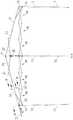
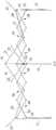
附图1是根据本发明的一种帐篷在展开状态时的示意图;Accompanying drawing 1 is the schematic diagram according to a kind of tent of the present invention when unfolding state;
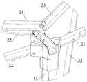
附图2是附图1中I处的局部放大图;Accompanying
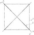
附图3是附图1所示帐篷的俯视图;Accompanying
附图4是附图3中A-A向的剖视图;Accompanying drawing 4 is the sectional view of A-A direction in accompanying
附图5是附图3中B-B向的剖视图;Accompanying drawing 5 is the sectional view of B-B direction in accompanying
附图6是附图3中C-C向的剖视图;Accompanying drawing 6 is the sectional view of C-C direction in accompanying
附图7是附图3中D-D向的剖视图;Accompanying drawing 7 is the sectional view of D-D direction in accompanying
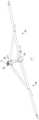
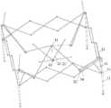
附图8是附图1所示的帐篷在折叠过程中的示意图;Accompanying drawing 8 is the schematic diagram of the tent shown in accompanying drawing 1 in the folding process;
附图9是附图8中I处的局部放大图;Accompanying drawing 9 is the partial enlarged view of I place among accompanying drawing 8;
附图10是附图8中II处的局部放大图;Accompanying drawing 10 is the partial enlarged view of II place among accompanying drawing 8;
附图11是附图8所示的帐篷的俯视图;Accompanying
附图12是附图11中A-A向的剖视图;Accompanying
附图13是附图8所示的帐篷进一步折叠后的示意图;Accompanying drawing 13 is the schematic diagram after the tent shown in accompanying drawing 8 is further folded;
附图14是附图1所示的帐篷在折叠状态时的示意图。Accompanying drawing 14 is a schematic diagram of the tent shown in accompanying drawing 1 in a folded state.
上述附图中,In the above drawings,
1、立柱组件;11、立柱上段;12、立柱下端;1. Column assembly; 11. Upper section of column; 12. Lower end of column;
2、顶杆组件;21、第一顶杆;22、第二顶杆;221、卡接部;23、挑檐杆;24、传动杆;241、卡接部;25、支撑杆;2. Push rod assembly; 21. First push rod; 22. Second push rod; 221. Clamping part; 23. Overhang rod; 24. Transmission rod; 241. Clamping part; 25. Support rod;
3、侧杆组件;30、十字撑杆件;31、第一连杆;32、第二连杆;3. Side bar assembly; 30. Cross brace; 31. First connecting rod; 32. Second connecting rod;
41、上中心连接件;42、下中心连接件;41. Upper center connector; 42. Lower center connector;
51、滑块;52、驱动杆。51, slide block; 52, driving rod.
具体实施方式detailed description
下面结合附图对本发明的较佳实施例进行详细阐述,以使本发明的优点和特征能更易于被本领域的技术人员理解。在此需要说明的是,对于这些实施方式的说明用于帮助理解本发明,但并不构成对本发明的限定。此外,下面所描述的本发明各个实施方式中所涉及到的技术特征只要彼此之间未构成冲突就可以互相结合。The preferred embodiments of the present invention will be described in detail below in conjunction with the accompanying drawings, so that the advantages and features of the present invention can be more easily understood by those skilled in the art. It should be noted here that the descriptions of these embodiments are used to help understand the present invention, but are not intended to limit the present invention. In addition, the technical features involved in the various embodiments of the present invention described below may be combined with each other as long as they do not constitute a conflict with each other.
本实施例提供一种带屋檐的可折叠帐篷,其具有较大的遮阳面积。参照附图1-14所示,可折叠帐篷,包括至少三个立柱组件1、与立柱组件1数量相同且一一对应的顶杆组件2,任意相邻两个立柱组件1的上端部之间分别连接有侧杆组件3。具体到本实施例中,立柱组件1的数量为四个,且等间隔排列而围绕形成立方体空间,立柱组件1大体沿竖直方向延伸以将帐篷支撑于地面上。顶杆组件2对应为四个,用于构成帐篷的顶架。侧杆组件3也对应为四个,分别位于帐篷的前后左右四周。This embodiment provides a foldable tent with eaves, which has a larger sunshade area. Referring to the accompanying drawings 1-14, the foldable tent includes at least three column assemblies 1, the same number of column assemblies 1 and one-to-one corresponding
参照附图2所示,各顶杆组件2分别包括自内至外依次设置的分别具有内端部和外端部的第一顶杆21、第二顶杆22以及挑檐杆23。本文中所定义的“内”、“外”等方位词都是以帐篷的竖直中心线为参照的,以离帐篷的竖直中心线较近为内,反之为外。四个顶杆组件2的四个第一顶杆21的内端部均通过枢轴可转动地连接于一上中心连接件41上,从而使得四个顶杆组件2构成分别沿帐篷顶架的对角线向帐篷的四个顶角延伸的十字形结构,且彼此可以相对转动。每个顶杆组件2中,第一顶杆21的外端部和第二顶杆22的内端部通过枢轴可转动地连接,第二顶杆22的外端部、挑檐杆23的内端部和对应立柱组件1的上端部两两相对转动地连接。换言之,第二顶杆22的外端部、挑檐杆23的内端部和对应立柱组件1的上端部三者可通过两个枢轴两两相接或通过同一枢轴转动连接,如,第二顶杆22的外端部和挑檐杆23的内端部通过一个枢轴转动连接,相对应的立柱组件1的上端部则通过另一个枢轴可第二顶杆22的外端部和挑檐杆23二者中的其中一个转动连接。具体到本实施例中,第二顶杆22的外端部、挑檐杆23的内端部通过同一个枢轴转动连接在对应的立柱组件1的上端部。Referring to FIG. 2 , each
每个顶杆组件2还分别包括连接于第一顶杆21和挑檐杆23之间的用于使挑檐杆23随第一顶杆21展开或折叠的传动件。典型地,传动件为可转动地连接于第一顶杆21和挑檐杆23之间的传动杆24,第一顶杆、第二顶杆、挑檐杆以及传动杆之间构成四连杆机构,四个杆联动而相互折叠和相对展开。传动杆24具有和第一顶杆21的外端部通过枢轴可转动地连接的内端部以及和挑檐杆23的内端部通过枢轴可转动地连接的外端部,其中,传动杆24和第一顶杆21的连接处C1位于第二顶杆22和第一顶杆21的连接处C2的外侧,传动杆24和挑檐杆23的连接处C3位于第二顶杆22和挑檐杆23的连接处的外侧,如附图2所示。Each
每个顶杆组件2还分别包括一个支撑杆25,支撑杆25通过枢轴可转动地设于第一顶杆21的内端部和外端部之间。四个顶杆组件2的支撑杆25的内端部均通过枢轴可转动地连接与一个下中心连接件42上,下中心连接件42位于上中心连接件41的正下方且二者的几何中心均位于帐篷的竖直中心线上。需要说明的是:同一顶杆组件2上的各枢轴的轴心线分别沿水平方向延伸且相互平行。Each
该帐篷具有展开状态和折叠状态,当帐篷在展开状态时,每个顶杆组件2的第一顶杆21、第二顶杆22以及挑檐杆23分别相对展开且挑檐杆23的外端部伸至对应立柱组件1的外侧;当帐篷在折叠状态时,每个顶杆组件2的第一顶杆21、第二顶杆22以及挑檐杆23分别相互靠拢。需要注意的是:当帐篷在展开状态时,每个顶杆组件2的第二顶杆22和传动杆24二者的中心线平行或构成小于10°的夹角。更为优选地,当帐篷在展开状态时,每个顶杆组件2的第一顶杆21、第二顶杆22、传动杆24和挑檐杆23四者的中心线平行,从而使得传动杆24可对第二顶杆22起到很好的加强作用,提高帐篷顶架的强度。更具体地,如附图2、5-7所示,每个顶杆组件2中,第一顶杆21和挑檐杆23的中心线共线,第二顶杆22和传动杆24分别位于所述第一顶杆21和挑檐杆23的中心线的相对两侧,连接较牢固且更稳定。此外,如附图5所示,除通过枢轴连接外,第二顶杆22上还固定设置或一体成形有U形的卡接部221,该卡接部221具有与第一顶杆21相配合的卡槽,第一顶杆21可卡在该卡槽内,从而使得展开状态下的帐篷更稳定;卡槽具有向上的槽口,第一顶杆21在转动时可脱离卡槽,而不会干涉帐篷的折叠。第一顶杆21与传动杆24之间也采用类似的连接方式,如附图6所示,传动杆24上也固定设置或一体成形有U形的卡接部241,该卡接部241具有与第一顶杆21相配合的卡槽,第一顶杆21可脱离地卡在该卡槽内。The tent has an unfolded state and a folded state. When the tent is in the unfolded state, the
各立柱组件1分别包括立柱上段11、可沿上下方向滑动地插设于立柱上段11内的立柱下段12。上述顶杆组件2的第二顶杆22、挑檐杆23分别转动连接于立柱上段11的上端部上。各立柱组件1的立柱上段11上分别套设有可沿上下方向滑动的滑块51。各顶杆组件2还分别包括具有上端部和下端部的驱动杆52,驱动杆52的上端部可转动地连接于传动杆24的内端部和外端部之间,驱动杆52的下端部可转动地连接于对应的滑块51,用于随滑块51移动而驱动传动杆24动作。Each column assembly 1 includes a column
侧杆组件3有一或多个依次相转动连接的十字撑杆件30构成,每个十字撑杆件30分别包括分别具有上端和下端的第一连杆31和第二连杆32,第一连杆31的中部和第二连杆32的中部通过枢轴相转动连接而交叉构成十字形结构。具体到本实施例中,每个侧杆组件3有三个十字撑杆件30构成,其中,第一连杆31的上端与一个立柱组件1的上端部或另一个十字撑杆件30的第二连杆32的上端相转动连接,第一连杆31的下端与另一个十字撑杆件30的第二连杆32的下端或另一个立柱组件1上的滑块51相转动连接,第二连杆32的下端与一个立柱组件1上的滑块51或另一个十字撑杆件30的第一连杆31的下端相转动连接,第二连杆32的上端与另一个十字撑杆件30的第一连杆31的上端或另一个立柱组件1的上端部相转动连接。The
当上述的帐篷在折叠时,先将设于上中心连接件41和/或各第一顶杆21之间的锁定机构解锁,该锁定机构可采用现有技术中已知的锁定方式,在此不做赘述;立柱组件1的立柱下段12收纳至立柱上段11内;将立柱组件1上的滑块51向下拉,带动驱动杆52转动,传动杆24随之转动,在传动杆24的作用下,第一顶杆21和第二顶杆22靠拢,挑檐杆23的外端部向上且向内转动;同时,随着顶杆组件2的收拢,立柱组件1之间也相互靠拢,从而侧杆组件3的各十字撑杆件30相互折叠靠拢;至滑块51移动至其最低位置时,各立柱组件1相互靠拢,各十字撑杆组件相互靠拢,各顶杆组件2相互收拢于立柱组件1之间,达到附图14所示的折叠状态。可以看出,折叠状态的帐篷整体结构紧凑,收折尺寸小;而且在折叠过程中,各杆件(包括挑檐杆23)都可在滑块51的带动下收折,不需要再单独折叠挑檐杆23,折叠操作方便。When the above-mentioned tent is being folded, the locking mechanism that is arranged between the upper central connecting
反之,当上述的帐篷在展开时,向上滑动滑块51,通过驱动杆52、传动杆24的彼此作用,各顶杆组件2的第一顶杆21、挑檐杆23相对第二顶杆22展开;立柱组件1、侧杆组件3随之被向四周撑开;至帐篷展开后,通过设于上中心连接件41和/或各第一顶杆21之间的锁定机构锁定使帐篷稳定处于如附图1所示的展开状态。在展开过程中,各杆件(包括挑檐杆23)都可在滑块51的带动下展开,不需要再单独展开挑檐杆23,展开方便;此外,在展开后,传动杆24对第二顶杆22有加强作用,使得顶杆组件2更稳定。Conversely, when the above-mentioned tent is unfolding, slide the
上述实施例只为说明本发明的技术构思及特点,是一种优选的实施例,其目的在于熟悉此项技术的人士能够了解本发明的内容并据以实施,并不能以此限定本发明的保护范围。凡根据本发明的原理所作的等效变换或修饰,都应涵盖在本发明的保护范围之内。The above-described embodiment is only to illustrate the technical concept and characteristics of the present invention. It is a preferred embodiment. Its purpose is that those familiar with this technology can understand the content of the present invention and implement it accordingly, and cannot limit the scope of the present invention. protected range. All equivalent changes or modifications made according to the principles of the present invention shall fall within the protection scope of the present invention.
Claims (10)
Priority Applications (7)
| Application Number | Priority Date | Filing Date | Title |
|---|---|---|---|
| CN201710679291.5ACN107476647B (en) | 2017-08-10 | 2017-08-10 | A collapsible tent |
| CN202211601366.5ACN116335471A (en) | 2017-08-10 | 2017-08-10 | Foldable tent |
| PCT/CN2017/100773WO2019028960A1 (en) | 2017-08-10 | 2017-09-06 | Foldable tent |
| JP2020506264AJP6913230B2 (en) | 2017-08-10 | 2017-09-06 | Foldable tent |
| US16/334,994US11230858B2 (en) | 2017-08-10 | 2017-09-06 | Foldable tent |
| EP17921021.6AEP3666995B1 (en) | 2017-08-10 | 2017-09-06 | Foldable tent |
| AU2017427137AAU2017427137B2 (en) | 2017-08-10 | 2017-09-06 | Foldable tent |
Applications Claiming Priority (1)
| Application Number | Priority Date | Filing Date | Title |
|---|---|---|---|
| CN201710679291.5ACN107476647B (en) | 2017-08-10 | 2017-08-10 | A collapsible tent |
Related Child Applications (1)
| Application Number | Title | Priority Date | Filing Date |
|---|---|---|---|
| CN202211601366.5ADivisionCN116335471A (en) | 2017-08-10 | 2017-08-10 | Foldable tent |
Publications (2)
| Publication Number | Publication Date |
|---|---|
| CN107476647A CN107476647A (en) | 2017-12-15 |
| CN107476647Btrue CN107476647B (en) | 2022-12-09 |
Family
ID=60599149
Family Applications (2)
| Application Number | Title | Priority Date | Filing Date |
|---|---|---|---|
| CN202211601366.5APendingCN116335471A (en) | 2017-08-10 | 2017-08-10 | Foldable tent |
| CN201710679291.5AActiveCN107476647B (en) | 2017-08-10 | 2017-08-10 | A collapsible tent |
Family Applications Before (1)
| Application Number | Title | Priority Date | Filing Date |
|---|---|---|---|
| CN202211601366.5APendingCN116335471A (en) | 2017-08-10 | 2017-08-10 | Foldable tent |
Country Status (6)
| Country | Link |
|---|---|
| US (1) | US11230858B2 (en) |
| EP (1) | EP3666995B1 (en) |
| JP (1) | JP6913230B2 (en) |
| CN (2) | CN116335471A (en) |
| AU (1) | AU2017427137B2 (en) |
| WO (1) | WO2019028960A1 (en) |
Families Citing this family (21)
| Publication number | Priority date | Publication date | Assignee | Title |
|---|---|---|---|---|
| US12084879B2 (en)* | 2016-07-26 | 2024-09-10 | Shengyong Yang | Collapsible canopy with reinforcement bars |
| US12037808B2 (en)* | 2018-05-29 | 2024-07-16 | Zhejiang Jiansheng Leisure Products Co., Ltd | Folding canopy with eave structure |
| CN108583939B (en)* | 2018-05-30 | 2021-04-20 | 南京航空航天大学 | Space unfolding mechanism applied to satellite solar wing |
| CN110593639A (en)* | 2018-11-12 | 2019-12-20 | 蔚孜电子商务(上海)有限公司 | Foldable tent with center lock and reinforced poles |
| CN109505454B (en)* | 2018-12-27 | 2024-04-26 | 浙江健盛休闲用品有限公司 | Folding tent with automatic cornice structure |
| AU2019101725A4 (en) | 2018-12-27 | 2020-04-16 | Zhejiang Jiansheng Leisure Products Co., Ltd | Folding tent with automatic cornice structure |
| CN114809793B (en)* | 2021-01-29 | 2025-07-29 | 临海市臻一工艺品有限公司 | Automatic cornice mechanism for folding tent |
| CN112922440B (en)* | 2021-02-02 | 2022-02-08 | 浙江健盛休闲用品有限公司 | Folding tent with layering tent roof |
| US11739557B2 (en)* | 2021-09-27 | 2023-08-29 | Ningbo Xinyuan Leisure Products Co. Ltd. | Easily extendable and retractable canopy mechanism |
| US12044028B2 (en)* | 2021-12-31 | 2024-07-23 | Zhejiang Hengfeng Top Leisure Co., Ltd. | Tent and tent pole thereof |
| USD970675S1 (en)* | 2022-01-26 | 2022-11-22 | Yongkang Chunkai Import & Export Co., Ltd | Tent |
| CN217841042U (en)* | 2022-03-17 | 2022-11-18 | 武义申华工贸股份有限公司 | Cornice awning connecting assembly |
| EP4536923A1 (en)* | 2022-06-10 | 2025-04-16 | GCI Outdoor LLC | Portable and collapsible canopy structure |
| US20240003486A1 (en)* | 2022-06-30 | 2024-01-04 | Sophia & William Brands Co., LTD | Semi-automatic overhanging plastic part for fixing and releasing an overhanging rod |
| US12139926B2 (en)* | 2022-07-19 | 2024-11-12 | Nengxiao LU | Folding tent eave automatically-overhanging structure applicable to eave overhanging rods in various lengths |
| USD1057388S1 (en)* | 2022-10-09 | 2025-01-14 | Ningbo Suntime Garden Furniture Co., Ltd. | Folding sunshade frame |
| USD1046051S1 (en)* | 2023-01-13 | 2024-10-08 | Wuyi Letu Leisure Products Co., Ltd | Folding tent frame with cantilevered roof |
| CN219672299U (en)* | 2023-02-08 | 2023-09-12 | 浙江永强集团股份有限公司 | A kind of anti-water accumulation folding awning |
| USD1069961S1 (en)* | 2024-11-12 | 2025-04-08 | Hui Zhou | Canopy |
| USD1069015S1 (en)* | 2024-11-12 | 2025-04-01 | Zhejiang Yatu E-commerce Co., Ltd | Canopy |
| USD1069014S1 (en)* | 2024-11-12 | 2025-04-01 | Hui Zhou | Canopy |
Citations (3)
| Publication number | Priority date | Publication date | Assignee | Title |
|---|---|---|---|---|
| CN202990554U (en)* | 2012-12-24 | 2013-06-12 | 杭州绿洲休闲用品有限公司 | Foldable tent |
| CN103590650A (en)* | 2013-09-18 | 2014-02-19 | 鹭谱达(厦门)户外用品有限公司 | Folding tent eave frame mechanism |
| CN207092685U (en)* | 2017-08-10 | 2018-03-13 | 蔚孜电子商务(上海)有限公司 | A kind of foldable tent |
Family Cites Families (16)
| Publication number | Priority date | Publication date | Assignee | Title |
|---|---|---|---|---|
| FR2438987A1 (en)* | 1978-10-17 | 1980-05-16 | Pitaud Bernard | Folding tent with permanently attached frame - consists of curved articulated poles joined at top to tensioning device via extending linkage |
| KR100429102B1 (en)* | 2002-03-28 | 2004-04-29 | 카라반인터내셔날 주식회사 | Loof formative structure for frame of folding tent |
| GB2397587B (en)* | 2003-01-23 | 2005-02-09 | Tony Tsai | A Tent structure |
| WO2008024565A2 (en)* | 2006-08-24 | 2008-02-28 | Hkd International (Hk) Limited | Mounting assembly for a collapsible canopy |
| CN201531150U (en)* | 2009-09-29 | 2010-07-21 | 厦门革新金属制造有限公司 | Eaves structure of tent |
| US8701692B2 (en)* | 2012-04-27 | 2014-04-22 | Pro Performance Sports, L.L.C. | Collapsible portable shelter |
| CN203547226U (en)* | 2013-09-13 | 2014-04-16 | 鹭谱达(厦门)户外用品有限公司 | Roof structure of folding tent |
| CN104358468B (en)* | 2014-11-05 | 2017-05-24 | 客贝利(厦门)休闲用品有限公司 | Water accumulation preventing high-top tent |
| CN204238639U (en)* | 2014-10-21 | 2015-04-01 | 鹭谱达(厦门)户外用品有限公司 | A kind of break camp eave frame mechanism |
| CN204370899U (en)* | 2014-12-05 | 2015-06-03 | 客贝利(厦门)休闲用品有限公司 | A kind of anistree eaves tent |
| US10246898B2 (en)* | 2015-06-01 | 2019-04-02 | Xiamen Innovation Metal Products Co., Ltd. | Centralized locking and unlocking mechanisms for tent frames and tent frames having same |
| CN206128828U (en)* | 2016-09-19 | 2017-04-26 | 客贝利(厦门)休闲用品有限公司 | Eaves structure of tent |
| CN206128833U (en)* | 2016-10-13 | 2017-04-26 | 客贝利(厦门)休闲用品有限公司 | Take tent structure of eave |
| CN206190220U (en)* | 2016-11-24 | 2017-05-24 | 成都保瑞特钻头有限公司 | Novel prevent mud drum PDC drill bit |
| CN206279870U (en)* | 2016-11-24 | 2017-06-27 | 客贝利(厦门)休闲用品有限公司 | A kind of tent frame rod with eaves |
| US10280645B1 (en)* | 2018-06-08 | 2019-05-07 | Zhejiang Hengfeng Top Leisure Co., Ltd. | Canopy frame with eave structure |
- 2017
- 2017-08-10CNCN202211601366.5Apatent/CN116335471A/enactivePending
- 2017-08-10CNCN201710679291.5Apatent/CN107476647B/enactiveActive
- 2017-09-06WOPCT/CN2017/100773patent/WO2019028960A1/ennot_activeCeased
- 2017-09-06EPEP17921021.6Apatent/EP3666995B1/enactiveActive
- 2017-09-06AUAU2017427137Apatent/AU2017427137B2/enactiveActive
- 2017-09-06JPJP2020506264Apatent/JP6913230B2/enactiveActive
- 2017-09-06USUS16/334,994patent/US11230858B2/enactiveActive
Patent Citations (3)
| Publication number | Priority date | Publication date | Assignee | Title |
|---|---|---|---|---|
| CN202990554U (en)* | 2012-12-24 | 2013-06-12 | 杭州绿洲休闲用品有限公司 | Foldable tent |
| CN103590650A (en)* | 2013-09-18 | 2014-02-19 | 鹭谱达(厦门)户外用品有限公司 | Folding tent eave frame mechanism |
| CN207092685U (en)* | 2017-08-10 | 2018-03-13 | 蔚孜电子商务(上海)有限公司 | A kind of foldable tent |
Also Published As
| Publication number | Publication date |
|---|---|
| AU2017427137B2 (en) | 2021-10-07 |
| JP6913230B2 (en) | 2021-08-04 |
| US11230858B2 (en) | 2022-01-25 |
| JP2020529542A (en) | 2020-10-08 |
| EP3666995A1 (en) | 2020-06-17 |
| CN107476647A (en) | 2017-12-15 |
| WO2019028960A1 (en) | 2019-02-14 |
| US20200157838A1 (en) | 2020-05-21 |
| EP3666995B1 (en) | 2023-06-07 |
| AU2017427137A1 (en) | 2020-03-19 |
| EP3666995A4 (en) | 2021-04-14 |
| CN116335471A (en) | 2023-06-27 |
Similar Documents
| Publication | Publication Date | Title |
|---|---|---|
| CN107476647B (en) | A collapsible tent | |
| CN207565662U (en) | Children trolley | |
| CN101463671A (en) | General type integral folding frame type tent frame | |
| US10227792B2 (en) | Tent having enhanced tent top | |
| CN112324238A (en) | Foldable tent | |
| CN110652138A (en) | Folding bed | |
| CN203987064U (en) | A kind of folding bed | |
| CN106037347A (en) | Foldable bed | |
| CN214424187U (en) | Foldable tent | |
| CN108477911A (en) | Travelling bed | |
| CN216861568U (en) | stroller | |
| CN107618558A (en) | Children trolley | |
| CN215485104U (en) | Foldable tent | |
| CN104326006B (en) | child umbrella handle vehicle | |
| US9546500B2 (en) | Tent frame | |
| CN209908071U (en) | Folding tent with automatic cornice structure | |
| CN219056343U (en) | a stroller for children | |
| CN211380493U (en) | a folding bed | |
| KR20190091059A (en) | Foldable gabled roof type canopy frame and canopy having the same | |
| CN207790804U (en) | A kind of children trolley | |
| CN209336784U (en) | Perambulator | |
| KR20200002155U (en) | Foldable gabled roof type canopy frame and canopy having the same | |
| CN219056338U (en) | stroller | |
| CN204236528U (en) | child umbrella handle vehicle | |
| CN206128836U (en) | Eaves structure of tent |
Legal Events
| Date | Code | Title | Description |
|---|---|---|---|
| PB01 | Publication | ||
| PB01 | Publication | ||
| SE01 | Entry into force of request for substantive examination | ||
| SE01 | Entry into force of request for substantive examination | ||
| GR01 | Patent grant | ||
| GR01 | Patent grant | ||
| CP03 | Change of name, title or address | ||
| CP03 | Change of name, title or address | Address after:Room 230A, Building 269, No. 3663 Zhongshan North Road, Putuo District, Shanghai, 200333 Patentee after:Weizi e-commerce (Shanghai) Co.,Ltd. Country or region after:China Address before:Room 214B, Building 358, No. 3663, North Zhongshan Road, Putuo District, Shanghai, 200062 Patentee before:Weizi e-commerce (Shanghai) Co.,Ltd. Country or region before:China |