CN107438983B - Compilers and methods for determining physical and virtual resources for software-defined networking, storage, and computing - Google Patents
Compilers and methods for determining physical and virtual resources for software-defined networking, storage, and computingDownload PDFInfo
- Publication number
- CN107438983B CN107438983BCN201580063364.7ACN201580063364ACN107438983BCN 107438983 BCN107438983 BCN 107438983BCN 201580063364 ACN201580063364 ACN 201580063364ACN 107438983 BCN107438983 BCN 107438983B
- Authority
- CN
- China
- Prior art keywords
- physical
- topology
- node
- map
- logical
- Prior art date
- Legal status (The legal status is an assumption and is not a legal conclusion. Google has not performed a legal analysis and makes no representation as to the accuracy of the status listed.)
- Active
Links
Images


Classifications
- H—ELECTRICITY
- H04—ELECTRIC COMMUNICATION TECHNIQUE
- H04L—TRANSMISSION OF DIGITAL INFORMATION, e.g. TELEGRAPHIC COMMUNICATION
- H04L45/00—Routing or path finding of packets in data switching networks
- H04L45/02—Topology update or discovery
- H—ELECTRICITY
- H04—ELECTRIC COMMUNICATION TECHNIQUE
- H04L—TRANSMISSION OF DIGITAL INFORMATION, e.g. TELEGRAPHIC COMMUNICATION
- H04L41/00—Arrangements for maintenance, administration or management of data switching networks, e.g. of packet switching networks
- H04L41/12—Discovery or management of network topologies
- H04L41/122—Discovery or management of network topologies of virtualised topologies, e.g. software-defined networks [SDN] or network function virtualisation [NFV]
- H—ELECTRICITY
- H04—ELECTRIC COMMUNICATION TECHNIQUE
- H04L—TRANSMISSION OF DIGITAL INFORMATION, e.g. TELEGRAPHIC COMMUNICATION
- H04L49/00—Packet switching elements
- H04L49/25—Routing or path finding in a switch fabric
- H04L49/252—Store and forward routing
- H—ELECTRICITY
- H04—ELECTRIC COMMUNICATION TECHNIQUE
- H04L—TRANSMISSION OF DIGITAL INFORMATION, e.g. TELEGRAPHIC COMMUNICATION
- H04L49/00—Packet switching elements
- H04L49/70—Virtual switches
Landscapes
- Engineering & Computer Science (AREA)
- Computer Networks & Wireless Communication (AREA)
- Signal Processing (AREA)
- Data Exchanges In Wide-Area Networks (AREA)
Abstract
Description
Translated fromChinese技术领域technical field
本发明涉及通信网络,存储设备和计算设备。网络可以是分组交换或电路交换。本发明特别涉及用于物理和虚拟网络里分组转发设备,计算设备,存储设备,虚拟交换机,虚拟机器和容器的配置方法。The present invention relates to communication networks, storage devices and computing devices. The network can be packet switched or circuit switched. The present invention particularly relates to configuration methods for packet forwarding devices, computing devices, storage devices, virtual switches, virtual machines and containers in physical and virtual networks.
背景资料Background information
分组交换网络(PSN)和计算领域的最新发展导致了软件定义网络(SDN)的概念。在本发明的内容里,我们把软件定义网络(SDN)当作为定义网络的高级规范(如,但不限于,高级编程语言或脚本语言)的能力和按此规范,通过一个自动过程指示相应的物理和虚拟网络,存储和计算资源。Recent developments in packet-switched networking (PSN) and computing have led to the concept of software-defined networking (SDN). In the context of this invention, we refer to software-defined networking (SDN) as the ability to define a high-level specification (such as, but not limited to, a high-level programming language or scripting language) of a network and to instruct the corresponding Physical and virtual network, storage and computing resources.
最近的发展可以在WO2010115060“管理虚拟交换机的方法和设备”,和WO2012082988“网络交换机的配置方法”里找到。Recent developments can be found in WO2010115060 "Method and apparatus for managing virtual switches", and WO2012082988 "Configuration method for network switches".
最近已经可能,使用一个开放式接口,通过一个标准化协议,根据所需要的转发行为,指示分组转发装置。目前领先的协议是OpenFlow,但本发明并不限制或约束于OpenFlow协议,而是本质上与其通用,并可以与提供给分组转发装置转发表的编程介入的未来协议共同工作。转发表包含的信息与传入分组和输入端口的信息匹配时,提供将分组转发出所需要的输出端口。Recently it has been possible to instruct the packet forwarding means according to the required forwarding behaviour by means of a standardized protocol using an open interface. The current leading protocol is OpenFlow, but the present invention is not limited or restricted to the OpenFlow protocol, but is generic in nature and can work with future protocols that provide programming intervention to the forwarding table of the packet forwarding device. When the information contained in the forwarding table matches that of the incoming packet and the input port, it provides the output port required to forward the packet out.
我们将称'分组转发设备'为'交换机'遍及本文档的其余部分,用于任何执行分组转发设备,不限于开放系统互连(OSI)的第2层。除了转发功能,交换机可能对分组提供额外的(多个)操作,例如,但不限于,在转发分组到它一个或多个输出端口前,进行监控和/或记录,和/或缓冲,和/或修改传入分组的包头和/或有效载荷。该交换机还可能不转发(阻止)分组。这些在除分组交换外,在分组上执行(多个)附加操作的器件,通常称为中间匣子,包括在本文档中使用的交换机定义。We will refer to a 'packet forwarding device' as a 'switch' throughout the remainder of this document for any device that performs packet forwarding, not limited to
最近,对在虚拟物理服务器上或容器里运行的虚似机里执行交换和中间匣子功能的兴趣在增长,典型地被称为网络功能虚拟化(NFV),允许更大的灵活性和敏捷性部署网络功能和降低成本的潜力。在本发明描述和专利要求的SDN编译器,应该有创建这些虚拟机或容器转发指令的能力。Recently, there has been a growing interest in performing switching and intermediate box functions in virtual machines running on virtualized physical servers or in containers, typically referred to as Network Functions Virtualization (NFV), allowing for greater flexibility and agility Potential to deploy network functions and reduce costs. The SDN compiler described in the present invention and claimed in the patent should have the ability to create these virtual machines or containers to forward instructions.
往交换机分布这些转发表,通常是由所谓的“SDN控制器'完成的。SDN控制器功能是在一个集中的地方(实施通常冗余),由此中央指定的转发表分布到,网络中的典型地理分布的交换机间。此外,在SDN控制器在其北行接口提供了物理和/或虚拟网络资源的集中视图,例如交换机在网络中,他们的拓扑结构,各个链接的状态。The distribution of these forwarding tables to the switches is usually done by a so-called 'SDN controller'. The SDN controller function is in a centralized place (implementation is usually redundant), whereby the centrally designated forwarding table is distributed to, Typically geographically distributed between switches. In addition, the SDN controller at its northbound interface provides a centralized view of physical and/or virtual network resources, such as switches in the network, their topology, and the status of individual links.
以上所述SDN和传统的网络之间的一个重要区别在于:对于在网络中的交换机的转发表是以集中的方式来计算的,而不是传统的网络以分布式方式操作,这是基于大量不同的网络控制协议。这允许SDN网络用户(用户在最广泛的意义上:例如,但不限于网络运营商,IT运营商,操作系统,应用程序,其他网络,其它SDN编译器)可以集中指定网络的期望行为,大大增强对网络的控制。此外,随着云计算的引入,计算,存储和网络资源之间的紧密集成和集中控制,已经成为一个强制性要求。An important difference between SDN and traditional networks described above is that the forwarding tables for switches in the network are computed in a centralized manner, as opposed to traditional networks that operate in a distributed manner, based on a number of different network control protocol. This allows SDN network users (users in the broadest sense: for example, but not limited to network operators, IT operators, operating systems, applications, other networks, other SDN compilers) to centrally specify the desired behavior of the network, greatly Enhance control over the network. Furthermore, with the introduction of cloud computing, tight integration and centralized control among computing, storage and network resources has become a mandatory requirement.
目前,网络产业的重点是编程介入分组转发设备的转发表。为了创建网络,存储和计算之间的紧密集成,也有必要为物理主机,虚拟主机和物理网络接口卡(NIC)提供指令。例如。一台主机可以被指令在其哪个接口发送分组到特定目的节点。例如,一台主机可以被指令接受哪个分组和丢弃哪个。例如。一个网络接口卡(NIC)可以被指令转发接受哪个分组和丢弃哪个。对软件定义网络,包括物理和虚拟网络,存储和计算资源需要一个全面的方法。At present, the focus of the network industry is to program the forwarding table of the packet forwarding device. In order to create tight integration between networking, storage and computing, it is also necessary to provide instructions for physical hosts, virtual hosts and physical network interface cards (NICs). E.g. A host can be instructed on which of its interfaces to send packets to a specific destination node. For example, a host can be instructed which packets to accept and which to drop. E.g. A network interface card (NIC) can be instructed to forward which packets to accept and which to drop. A comprehensive approach to software-defined networking, including physical and virtual networking, storage and computing resources, is required.
在计算领域已成为普遍的做法来虚拟物理服务器到一个或多个虚拟机,从而导致上述的云计算。服务器虚拟化过程中产生物理计算资源的逻辑抽象。鉴于当今的计算机和网络之间的紧密集成,有必要开发一种用于物理和虚拟网络资源的逻辑抽象。It has become common practice in the computing field to virtualize a physical server into one or more virtual machines, leading to the aforementioned cloud computing. The logical abstraction of physical computing resources generated during server virtualization. Given the tight integration between today's computers and networks, it is necessary to develop a logical abstraction for physical and virtual network resources.
US 2013/058215公开了一个虚拟器,用于管理通过一个网络转发数据的多个被管理的交换元件。虚拟器包括用于存储输入逻辑转发平面数据的一个第一组表和用于存储输出物理控制平面数据的一个第二组表。它还包括一个表映射引擎,用于通过在第一组表中的输入逻辑转发平面数据上执行一组数据库连接操作来将第一组表中的输入逻辑转发平面数据映射到第二组表中的物理控制平面数据。在一些实施例中,物理控制平面数据随后被转换成物理转发行为,其指导被管理的交换元件转发数据。在该现有技术文献中,被管理的交换机将该物理控制平面数据转换成物理转发平面数据指定被管理交换机的转发行为(参照[0197]),其缺点是对物理节点加于要求执行转换并在所述物理节点中使用资源。在US2013/044641提出的现有技术,是创建一个覆盖虚拟网络,在本申请中的术语一个逻辑网络,基于底层里的隧道,通常是基于IP的网络。这个方法的缺点是操作虚拟重叠网络和底层网络,使操作复杂。此外,现有技术的缺点,根据US2013/044641一个虚拟节点的模型,在本申请的术语一个逻辑节点,在一个物理节点之后,是基于网络元件的连续性配置操作和管理网络,而不是基于网络服务。US 2013/058215 discloses a virtualizer for managing multiple managed switching elements that forward data over a network. The virtualizer includes a first set of tables for storing incoming logical forwarding plane data and a second set of tables for storing outgoing physical control plane data. It also includes a table mapping engine for mapping input logical forwarding plane data in the first set of tables to the second set of tables by performing a set of database join operations on the input logical forwarding plane data in the first set of tables physical control plane data. In some embodiments, the physical control plane data is then translated into physical forwarding actions, which direct the managed switching elements to forward the data. In this prior art document, the managed switch converts this physical control plane data into physical forwarding plane data to specify the forwarding behavior of the managed switch (see [0197]), which has the disadvantage of imposing a requirement on the physical node to perform the conversion and Resources are used in the physical node. The prior art proposed in US2013/044641 is to create an overlay virtual network, termed a logical network in this application, based on tunnels in the underlying layer, usually an IP-based network. The disadvantage of this method is that the operation of the virtual overlay network and the underlying network complicates the operation. Furthermore, the disadvantages of the prior art, according to the model of a virtual node in US2013/044641, in this application the term a logical node, after a physical node, is based on the continuous configuration of network elements to operate and manage the network, not based on the network Serve.
发明概要Summary of Invention
本专利申请要求来自未预先公布的EP14185824.1,但已在2014年9月22日提出。This patent application claims from EP14185824.1 which was not pre-published, but was filed on September 22, 2014.
本专利申请要求来自未预先公布的EP14185828.2,但已在2014年9月22日提出。This patent application claims from EP14185828.2 which was not pre-published but was filed on September 22, 2014.
与本申请同一发明者未预先公开的专利申请PCT/EP2014/055640描述了用于上述计算和网络之间的紧密集成的方法和编译器,以及逻辑抽象物理和虚拟网络资源的需要。Patent application PCT/EP2014/055640, not prepublished by the same inventor as the present application, describes methods and compilers for the above-mentioned tight integration between computing and networking, and the need to logically abstract physical and virtual network resources.
因此,PCT/EP2014/055640描述了用于翻译或编译一个高层次的网络规范到一组指令用于适当的物理和/或虚拟网络和/或计算资源的方法。这些指令陈述对传入的分组要执行的操作,如转发,接收,丢弃传入分组,以及如何从源节点发送分组。Accordingly, PCT/EP2014/055640 describes a method for translating or compiling a high-level network specification into a set of instructions for appropriate physical and/or virtual network and/or computing resources. These instructions state what to do with incoming packets, such as forwarding, receiving, discarding incoming packets, and how to send the packets from the source node.
在PCT/EP2014/055640中所述的发明还涉及用于执行这个方法的SDN编译器的布置。The invention described in PCT/EP2014/055640 also relates to the arrangement of an SDN compiler for performing this method.
为了完成这一任务,SDN编译器保留了每个逻辑网络通过高层次的网络规范定义的模型。另外,在SDN编译保留了物理和/或虚拟网络和/或计算资源的模型。这两个模型以及它们之间的关系表示于一组关系,如矩阵。逻辑网络包括逻辑节点。每个逻辑源和逻辑目的节点之间的转发通路是通过执行于这些矩阵的操作,产生一个物理和虚拟资源附着点(Points-of-Attachments,PoA)列表,确定的,(例如,但不限于以太网媒体接入控制(MAC)地址))。上述相应的指令是从这些转发通路存储在矩阵导出的。上述方法允许在相同的物理和虚拟资源上定义和建立多个同时逻辑网络。To accomplish this task, the SDN compiler maintains a model of each logical network defined by a high-level network specification. Additionally, SDN compilation preserves a model of physical and/or virtual network and/or computing resources. The two models and the relationship between them are represented by a set of relationships, such as matrices. A logical network includes logical nodes. The forwarding path between each logical source and logical destination node is determined by performing operations on these matrices to generate a list of physical and virtual resource Points-of-Attachments (PoA), (for example, but not limited to Ethernet Media Access Control (MAC) address)). The corresponding instructions above are derived from these forwarding paths stored in the matrix. The above method allows multiple simultaneous logical networks to be defined and established on the same physical and virtual resources.
在PCT/EP2014/055640中描述的方法可以适用于目前可用的基于OpenFlow的产品,但并不限于OpenFlow,并可能与提供分组转发装置转发表介入编程访问未来协议共同使用。所描述的方法可以用于目前广泛使用的附着点(PoA)的识别符,如以太网MAC地址。所描述的方法可以用于IPv4和IPv6的命名和分组的格式。The method described in PCT/EP2014/055640 may be applicable to currently available OpenFlow based products, but is not limited to OpenFlow, and may be used in conjunction with future protocols providing forwarding table intervention for packet forwarding devices. The described method can be used for currently widely used Point of Attachment (PoA) identifiers such as Ethernet MAC addresses. The described method can be used for IPv4 and IPv6 naming and packet formats.
发明描述在PCT/EP2014/055640里,不需要任何物理节点转换,创建可直接用于对传入分组作出转发决定的转发项,允许实现较不复杂的转发硬件和软件转发。所描述的发明不需要底层网络,简化了操作,通过使用逻辑名称空间到物理网络资源编译逻辑网络。所描述的发明使用基于有向图的网络抽象,允许SDN编译器用户,基于声明性请求指定的网络服务,及容可一个实施和维护所述网络服务,简化操作,并允许指定,实施和维护复杂的网络服务的SDN编译器。The invention is described in PCT/EP2014/055640, without any physical node switching, creating forwarding entries that can be used directly to make forwarding decisions on incoming packets, allowing for less complex forwarding hardware and software forwarding. The described invention does not require an underlying network and simplifies the operation by compiling logical networks using logical namespaces to physical network resources. The described invention uses a directed graph-based network abstraction that allows SDN compiler users to specify network services based on declarative requests, and enables one to implement and maintain said network services, simplify operations, and allow specification, implementation, and maintenance. SDN compiler for complex web services.
一个基于云的IT(信息技术)环境中的目标是部署逻辑存储和逻辑计算,以及以对物理和/或虚拟资源的最佳方式和要求从逻辑存储和逻辑计算构建的应用程序。目前,网络是在这个过程中的瓶颈,而理想的逻辑网络是对物理和/或虚拟资源以最佳方式和需要的部署,并是与逻辑存储和逻辑计算结合的。The goal in a cloud-based IT (information technology) environment is to deploy logical storage and logical computing, and applications built from logical storage and logical computing in an optimal manner and requirement for physical and/or virtual resources. Currently, the network is the bottleneck in this process, and the ideal logical network is the deployment of physical and/or virtual resources in the best way and as needed, combined with logical storage and logical computing.
PCT/EP2014/055640描述了一个用于翻译或编译的高级别网络规范到一组指令用于适当的物理和/或虚拟网络和/或计算资源的方法。该方法中描述于PCT/EP2014/055640 describes a method for translating or compiling a high-level network specification into a set of instructions for appropriate physical and/or virtual network and/or computing resources. The method is described in
PCT/EP2014/055640可应用于一个整体网络,其中最高层的逻辑节点表示逻辑存储或逻辑计算,并其一个请求-拓扑-级别-通路表示一个逻辑消息-流。PCT/EP2014/055640 can be applied to an overall network in which the logical node at the highest level represents logical storage or logical computation, and a request-topology-level-path represents a logical message-flow.
本发明的一个目的是对于物理和/或虚拟资源以最佳方式编译逻辑计算,存储和网络,从而根据逻辑计算,存储和网络要求选择的物理和/或虚拟资源。It is an object of the present invention to optimally compile logical computing, storage and networking for physical and/or virtual resources, thereby selecting physical and/or virtual resources according to logical computing, storage and networking requirements.
为此目的,本发明提供了一个方法,即权利要求1。For this purpose, the present invention provides a method, namely
在PCT/EP2014/055640中描述的SDN编译方法扩展到,根据SDN编译器的用户指定的逻辑节点,逻辑拓扑映射和任选逻辑第一层-映射的要求,通过一个SDN编译器,确定深度映射,涉及不同的深度的节点。所述扩展允许SDN编译器的用户指定的逻辑节点,及逻辑节点,逻辑拓扑-映射的要求,和逻辑拓扑-映射,和任选逻辑层-映射和逻辑层-映射的要求,并且已经所述SDN编译确定物理和/或虚拟资源,包括物理节点和物理链路,针对所述逻辑规范可被编译,从而确定逻辑节点和物理节点之间的关系作为由深度-映射,物理拓扑-通路,以及任选物理表示层-映射。The SDN compilation method described in PCT/EP2014/055640 is extended to, through an SDN compiler, determine the depth mapping according to the requirements of the SDN compiler's user-specified logical nodes, logical topology mappings and optional logical first-layer-mappings , involving nodes of different depths. The extension allows user-specified logical nodes of the SDN compiler, and logical nodes, logical topology-mapping requirements, and logical topology-mapping requirements, and optional logical layer-mapping and logical layer-mapping requirements, and have been described SDN compilation determines physical and/or virtual resources, including physical nodes and physical links, for which logical specifications can be compiled to determine relationships between logical nodes and physical nodes as defined by depth-map, physical topology-path, and Optional physical presentation layer-mapping.
附图简述Brief Description of Drawings
本发明将参考一些附图详细地进行说明是仅旨在表明本发明的实施方案,而不是限制范围。本发明的范围在所附权利要求和其技术等同限定。即,本领域技术人员将理解的用于解释本发明的特征,部件,元件等,除非另有说明,可以用技术上的同等代替。此外,不同实施方案的单独的特征可以组合,即使在附图中没有明确表明或说明书中没有明确解释,除非这种组合在物理上是不可能的。The present invention will be described in detail with reference to some of the accompanying drawings, which are intended only to illustrate embodiments of the invention and not to limit the scope. The scope of the present invention is defined by the appended claims and their technical equivalents. That is, features, components, elements, etc., which are understood by those skilled in the art to explain the present invention, may be replaced by technical equivalents unless otherwise specified. Furthermore, individual features of different embodiments may be combined even if not explicitly indicated in the drawings or explicitly explained in the description, unless such combination is physically impossible.
附图示出:The attached figure shows:
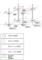
图1是一个软件定义网络的各种组件的描绘图Figure 1 is a depiction of the various components of a software-defined network
图2A是一个表示图示出了物理节点BA,BB,BC和BD功能Figure 2A is a representation diagram showing physical nodes BA, BB, BC and BD functions
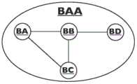
图2B是一个示出物理网络BAA功能的表示图,包括通过链路互连的物理节点BA,BB,BC和BD。Figure 2B is a representation showing the functionality of a physical network BAA, including physical nodes BA, BB, BC and BD interconnected by links.
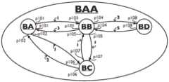
图2C是一个示出物理网络BAA功能的表示图,包括通过链路互连的物理节点BA,BB,BC和BD,其中一个物理节点和一个物理链路之间的互连是由一个物理附着点(PoA)来表示,p101至p108,其中示出了物理链路在每个方向上的物理通路的成本。Figure 2C is a diagram showing the function of a physical network BAA, including physical nodes BA, BB, BC and BD interconnected by links, wherein the interconnection between a physical node and a physical link is formed by a physical attachment Points (PoA) are indicated, p101 to p108, where the cost of the physical path of the physical link in each direction is shown.
图2D是一个图示出了一个加权有向图表示的物理网络BAA,包括由边互连的顶点(节点)BA,BB,BC和BD,其中一个顶点和一个边之间的互连是由一个物理附着点(PoA)表示的,p101至p108,其中示出了各个边的成本Figure 2D is a diagram showing a physical network BAA represented by a weighted directed graph, including vertices (nodes) BA, BB, BC and BD interconnected by edges, where the interconnection between a vertex and an edge is defined by Represented by a Physical Point of Attachment (PoA), p101 to p108, showing the cost of each edge
图3A是一个图示出了网络KA和KB和它们拓扑-映射的关系Figure 3A is a diagram showing networks KA and KB and their topology-mapping relationships
图3B是一个图示出了网络KA,KB,KC,KD和其映射的关系,为一个拓扑-映射或一个层-映射。FIG. 3B is a diagram showing the relationship of the networks KA, KB, KC, KD and their mappings as a topology-map or a layer-map.
图3C是示出网络KA,KB,KC,KD,LA,LB,LC,LD和其映射的关系,其为一个拓扑-映射,一个层-映射或一个深度-映射。FIG. 3C is a diagram showing the relationship of the networks KA, KB, KC, KD, LA, LB, LC, LD and their mappings, which are a topology-map, a layer-map or a depth-map.
图3D是一个图示出了在深度h的网络的KA,KB,KC,KD,LA,LB,LC,LD和它们的映射关系,以及在深度h+1的网络KAA,KCC,LAA,LCC。在(d,n,h+1)的网络KAA包含两个在(d,n,h)的网络KA和KB。在(d,n+1,h+1)的网络KCC包含两个在(d,n+1,h)的网络KC和KD。在(d+1,n+1,h+1)的网络LCC包含两个在(d+1,n+1,h)的网络LC和LD。在图3C中所示出的节点KA和KD,KB和KC,LA和LD,LB和LC之间的对角线层-映射在该图中被省略,以简化图。在图3C中所示出的节点KA和LA,KB和LA,KC和LD,KD和LC,KA和LC,KC和LA,KB和LD,KD和LB的对角线层-映射在该图中被省略,以简化图。Figure 3D is a diagram showing the KA, KB, KC, KD, LA, LB, LC, LD and their mapping relationships of the network at depth h, and the network KAA, KCC, LAA, LCC at
图4A是一个图示出了在(d,n,h+2)的NAAA网络包括在(d,n,h+1)的网络NAA,NCC和NEE。网络NAA包括在(d,n,h)的网络NA和NB。网络NCC包括在(d,n,h)的网络NC和ND。网络NEE包括在(d,n,h)的网络NE和NF。图4A还示出了在(d,n,h)的网络之间的拓扑-映射。Figure 4A is a diagram showing that the NAAA network at (d,n,h+2) includes the networks NAA, NCC and NEE at (d,n,h+1). The network NAA includes the networks NA and NB at (d,n,h). The network NCC includes the networks NC and ND at (d,n,h). The network NEE includes the networks NE and NF at (d,n,h). Figure 4A also shows the topology-mapping between the networks of (d,n,h).
图4B是一个图示出了在(d,n,h+2)的NAAA网络包括在(d,n,h+1)的网络NAA,NCC和NEE。网络NAA包括在(d,n,h)的网络NA和NB。网络NCC包括在(d,n,h)的网络NC和ND。网络NEE包括在(d,n,h)的网络NE和NF。图4B还示出了在(d,n,)的网络之间的层-映射以及在(d,n,h)的网络之间的拓扑-映射。Figure 4B is a diagram showing that the NAAA network at (d,n,h+2) includes the networks NAA, NCC and NEE at (d,n,h+1). The network NAA includes the networks NA and NB at (d,n,h). The network NCC includes the networks NC and ND at (d,n,h). The network NEE includes the networks NE and NF at (d,n,h). Figure 4B also shows the layer-mapping between the networks of (d,n,) and the topology-mapping between the networks of (d,n,h).
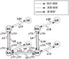
图5A是一个图示出了网络KA,KB,KC,KD,LA,LB,LC,LD和网络KA和网络KB之间的拓扑-映射,网络KA和网络KC之间的一个层-映射,网络的KB和网络KD之间的一个层-映射,网络KA和网络LA之间的一个深度-映射,网络KB和网络的LB之间的一个深度-映射,网络KC和网络的LC之间的一个深度-映射之间的一个深度-映射,以及网络KD和网络LD之间的一个深度-映射。另外,示出了拓扑-映射和层-映射的附着点(PoA)。Figure 5A is a diagram showing the topology-mapping between the network KA, KB, KC, KD, LA, LB, LC, LD and the network KA and the network KB, a layer-mapping between the network KA and the network KC, A layer-mapping between network KB and network KD, a depth-mapping between network KA and network LA, a depth-mapping between network KB and network LB, and a depth-mapping between network KC and network LC A depth-map between a depth-map, and a depth-map between the network KD and the network LD. Additionally, topology-map and layer-map Points of Attachment (PoAs) are shown.
图5B是一个图示出了网络KA,KB,KC,KD,LA,LB,LC,LD和拓扑-映射,层-映射和深度-映射的命名。另外,示出了拓扑-映射和层-映射的附着点(PoA)。Figure 5B is a diagram showing the names of networks KA, KB, KC, KD, LA, LB, LC, LD and topology-map, layer-map and depth-map. Additionally, topology-map and layer-map Points of Attachment (PoAs) are shown.
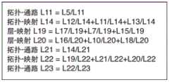
图5C是一个图示出了网络KA,KB,KC,KD,LA,LB,LC,LD和计算并存储从网络的LA到网络LB命名为L14的一个拓扑-映射为一个级联其由从网络LA到网络KA命名为L12的一个深度-映射,从网络KA到网络KB命名为L11的一个拓扑-映射,从网络KB到网络LB命名为L13的深度-映射所组成,命名为L11拓扑-通路是从网络KA到网络KB命名为L11的一个单个拓扑-映射Figure 5C is a diagram showing a topology of networks KA, KB, KC, KD, LA, LB, LC, LD and computing and storing from network LA to network LB named L14-mapped as a cascade which consists of A depth-mapping from network LA to network KA named L12, a topology-mapping from network KA to network KB named L11, consisting of a depth-mapping named L13 from network KB to network LB, named L11 topology- A path is a single topology-map named L11 from network KA to network KB
图5D是一个图示出了网络KA,KB,KC,KD,LA,LB,LC,LD和附加于图5C的是计算并存储从网络LC到网络LA命名为L19的一个层-映射为一个级联其由从网络LC到网络KC命名为L17的一个深度-映射,从网络KC和网络KA命名为L7的一个层-映射,以及从网络KA和网络LA命名为L15的一个深度-映射所组成和计算并存储从网络LB到网络LD命名为L20的一个层-映射为一个级联其由从网络LB到网络KB命名为L16的一个深度-映射,从网络KB和网络LD命名为L10的一个层-映射,以及从网络KD和网络LD命名为L18的一个深度-映射所组成。Figure 5D is a diagram showing the network KA, KB, KC, KD, LA, LB, LC, LD and attached to Figure 5C is a layer that computes and stores from the network LC to the network LA named L19-mapped to a The cascade consists of a depth-map named L17 from network LC to network KC, a layer-map named L7 from network KC and network KA, and a depth-map named L15 from network KA and network LA. Compose and compute and store a layer-map named L20 from Network LB to Network LD as a concatenation consisting of a depth-map from Network LB to Network KB named L16, from Network KB and Network LD named L10 A layer-map, and a depth-map named L18 from network KD and network LD.
图5E是一个图示出了网络KA,KB,KC,KD,LA,LB,LC,LD和附加于图5D的是计算并存储从网络LC到网络LD命名为L22的一个拓扑-映射为一个级联其由从网络LC到网络LA命名为L19的一个层-映射,从网络LA和网络LB命名为L21的一个拓扑-通路,以及从网络LB和网络LD命名为L20的一个层-映射所组成,命名为L21的拓扑-通路是从网络LA到网络LB命名为L14的一个单个拓扑-映射。Figure 5E is a diagram showing the network KA, KB, KC, KD, LA, LB, LC, LD and attached to Figure 5D is a topology that is computed and stored from the network LC to the network LD named L22 - mapped to a The cascade consists of a layer-map named L19 from network LC to network LA, a topology-path named L21 from network LA and network LB, and a layer-mapping named L20 from network LB and network LD. The constituent, topology-path named L21 is a single topology-map named L14 from network LA to network LB.
图5F是一个图示出了网络KA,KB,KC,KD,LA,LB,LC,LD和附加于图5E的是计算并存储从网络LC到网络LD命名为L22的一个拓扑-通路为从网络LC到网络LD命名为L22的一个单个拓扑-映射。Figure 5F is a diagram showing the network KA, KB, KC, KD, LA, LB, LC, LD and attached to Figure 5E is a topology that computes and stores from the network LC to the network LD named L22 - the path is from A single topology-map of network LC to network LD named L22.
图6A是一个图示出了用于从一个第一个网络到一个第二个网络的一个第一个映射-类型的一个第一个映射与一个第一个映射的命名的表示法。6A is a diagram illustrating a first-mapping-type representation of a first-mapping and a first-mapping naming for a first-mapping from a first network to a second network.
图6B是一个图示出了用于从一个第二个网络到一个第三个网络的一个第二个映射-类型的一个第二个映射与一个第二个映射的命名的表示法。Figure 6B is a diagram showing a second mapping from a second network to a third network - a second mapping of types and a named representation of a second mapping.
图6C是一个图示出了用于一个第三个边-类型的一个第三个边与一个第三个边的命名,其为一个级联其由一个第一个边与一个第一个边的命名和一个第一个边与一个第一个边的命名所组成的表示法。Figure 6C is a diagram showing the naming of a third edge and a third edge for a third edge-type, which is a concatenation consisting of a first edge and a first edge and a notation consisting of the name of the first edge and the name of the first edge.
图6D是一个图示出了用于一个第三个边-类型的一个第三个边与一个第三个边的命名,其为一个级联其由一个第一个映射与一个第一组边-关系和一个第二个映射与一个第二组边-关系所组成的表示法。Figure 6D is a diagram showing the naming of a third edge and a third edge for a third edge-type, which is a concatenation which consists of a first mapping with a first set of edges -Relation and a second map with a second set of edge-relationship notation.
图7A是一个图示出了拓扑-映射L5和L6,层-映射L7,L8,L9和L10以及深度-映射L12,L13,L15,L16,L17,L18,L24和L25。Figure 7A is a diagram showing topology-maps L5 and L6, layer-maps L7, L8, L9 and L10 and depth-maps L12, L13, L15, L16, L17, L18, L24 and L25.
图7B是一个图示出了拓扑-映射L14和L22,层-映射L19和L20和拓扑-通路L11,L21和L23。Figure 7B is a diagram showing topology-maps L14 and L22, layer-maps L19 and L20 and topology-paths L11, L21 and L23.
图7C是一个图示出了在步骤1中的从网络LC到网络LD命名为L23的拓扑-通路和在步骤6中从网络的LC到网络LD命名为L23的拓扑-通路的递归-通路,步骤2至步骤5是计算的中间步骤。Figure 7C is a diagram showing the recursive-path from the network LC to the network LD named L23 topology-path in
图8是一个图示出了在(d=1,n=0,h=2)的逻辑网络NAAA包含在(d=1,n=0,h=1)的逻辑网络NAA,NCC和NEE。逻辑网络NAA包含在(d=1,n=0,h=1)的逻辑网络NA和NB。网络NCC包含在(d=1,n=0,h=1)的逻辑网络NC和ND。逻辑网络NEE包含在(d=1,n=0,h=1)的网络NE和NF。图8还示出了在(d=0,n=0,h=0)的物理网络QA,QB,QC,QD,QE和QF。图8还示出了拓扑-映射,深度-映射,级-映射和网络之间的拓扑-通路,以及每个拓扑-映射的名称,平映射和拓扑-通路和边-关系。Figure 8 is a diagram showing that the logical network NAAA at (d=1, n=0, h=2) contains the logical networks NAA, NCC and NEE at (d=1, n=0, h=1). The logical network NAA contains logical networks NA and NB in (d=1, n=0, h=1). The network NCC contains logical networks NC and ND in (d=1, n=0, h=1). The logical network NEE contains the networks NE and NF in (d=1, n=0, h=1). Figure 8 also shows the physical networks QA, QB, QC, QD, QE and QF at (d=0, n=0, h=0). Figure 8 also shows topology-maps, depth-maps, level-maps and topology-paths between networks, as well as the name of each topology-map, flat-map and topology-paths and edge-relationships.
图9是一个图示出了SDN编译器装置的一个例子,包括一个数据库,一个事件处理程序和一个指令程序。图9还示出了一个用户和SDN控制器和一个SDN节点和51至61的消息流。FIG. 9 is a diagram illustrating an example of an SDN compiler apparatus including a database, an event handler and an instruction program. Figure 9 also shows the message flow of a subscriber and SDN controller and an SDN node and 51 to 61.
图10是计算机装置的概要Fig. 10 is an overview of a computer device
图11A是一个图示出了一个逻辑节点FE,一个逻辑节点FF和一个逻辑节点FG。图11A还示出了从逻辑节点FE到逻辑节点FF的拓扑-映射和从逻辑节点FF到逻辑节点FG的拓扑-映射,表示为一个图里的有向边。FIG. 11A is a diagram showing one logical node FE, one logical node FF and one logical node FG. Figure 11A also shows the topology-mapping from logical node FE to logical node FF and the topology-mapping from logical node FF to logical node FG, represented as directed edges in a graph.
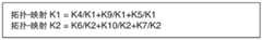
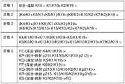
图11B是一个图示出了在(d=1,n=0,h=0)的一个逻辑节点的FE,在(d=1,n=0,h=0)的一个逻辑节点FF和在(d=1,n=0,h=0)的一个逻辑节点FG,在(d=0,n=0,h=0)的一个未知物理节点?X1,在(d=0,n=0,h=0)的一个未知物理节点?X2的和在(d=0,n=0,h=0)的一个未知物理节点?X3。图11B还示出了命名为K1和K2的拓扑-映射,命名为K3至K8的深度-映射,和命名为?K9和K10的未知物理拓扑-通路,在一个图里表示为有向边。在FIG. 11B is a diagram showing the FE of a logical node at (d=1, n=0, h=0), a logical node FF at (d=1, n=0, h=0) and the A logical node FG at (d=1,n=0,h=0), an unknown physical node at (d=0,n=0,h=0)? X1, an unknown physical node at (d=0,n=0,h=0)? The sum of X2 is at an unknown physical node at (d=0,n=0,h=0)? X3. Figure 11B also shows topology-maps named K1 and K2, depth-maps named K3 to K8, and ? The unknown physical topology of K9 and K10 - paths, represented as directed edges in a graph. exist
图11B的问号表示未知物理节点和未知物理拓扑-通路。The question marks of FIG. 11B represent unknown physical nodes and unknown physical topology-paths.
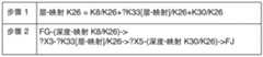
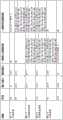
图11C是一个图示出了根据图6A的表示法,命名为K8至K3的深度-映射。Figure 11C is a diagram showing depth-maps named K8 to K3 according to the representation of Figure 6A.
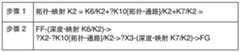
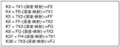
图11D是一个图示出了根据图6C的表示法,拓扑-映射K1和K2。在图11D“?K9[拓扑-通路]'表示K9是一个未知拓扑-通路,以及'?K10[拓扑-通路]'表示K10是一个未知拓扑-通路。Figure 11D is a diagram showing topology-maps K1 and K2 according to the representation of Figure 6C. In Figure 11D '?K9[topology-pathway]' indicates that K9 is an unknown topology-pathway, and '?K10[topology-pathway]' indicates that K10 is an unknown topology-pathway.
图11E是一个图示出了命名为K1拓扑-映射。Figure 11E is a diagram showing a topology-map named K1.
图11F是一个图示出了命名为K2的拓扑-映射。Figure 11F is a diagram showing the topology-map named K2.
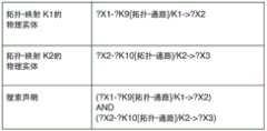
图11G是一个图示出了命名为K1的拓扑-映射的物理实体,命名为K2的拓扑-映射的物理实体图,和一个搜索声明。Figure 11G is a diagram illustrating a topology-mapped physical entity named K1, a topology-mapped physical entity named K2, and a search statement.
图11H是一个图示出了一个逻辑拓扑-映射的要求如何相关与一个未知物理拓扑-通路的要求。Figure 11H is a diagram showing how a logical topology-map requirement relates to an unknown physical topology-path requirement.
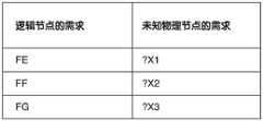
图11I是一个图示出了一个逻辑节点的要求如何相关与一个未知物理节点的要求。Figure 11I is a diagram showing how the requirements of a logical node relate to the requirements of an unknown physical node.
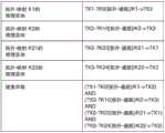
图12A是一个图示出了由物理节点KP表示的一个第一个计算设备,由物理节点KQ表示的一个第一个分组转发系统,由物理节点KR表示的一个第二个分组转发系统,由物理节点KS表示的一个第二个计算设备,和由物理节点KT表示的一个第三个计算设备,由拓扑-映射连接为物理链路。图12A还示出了P211至P218的附着点(PoA)。Figure 12A is a diagram showing a first computing device represented by physical node KP, a first packet forwarding system represented by physical node KQ, a second packet forwarding system represented by physical node KR, represented by A second computing device, represented by the physical node KS, and a third computing device, represented by the physical node KT, are connected as physical links by topology-map. Figure 12A also shows the point of attachment (PoA) of P211 to P218.
图12B是一个图示出了在(d=0,n=0,h=0)的一个物理节点KP,在(d=0,n=0,h=0)的一个物理节点KQ,在(d=0,n=0,h=0)的一个物理节点KS和在(d=0,n=0,h=0)的一个物理节点KT。图12B还示出了命名为K11至K18的拓扑-映射,表示为一个图里的有向边。Figure 12B is a diagram showing a physical node KP at (d=0, n=0, h=0), a physical node KQ at (d=0, n=0, h=0), at ( One physical node KS at d=0, n=0, h=0) and one physical node KT at (d=0, n=0, h=0). Figure 12B also shows topology-maps named K11 to K18, represented as directed edges in a graph.
图12C是一个图示出了根据图6A的表示法,命名为K11至K18的拓扑-映射。Figure 12C is a diagram showing topology-maps named K11 to K18 according to the representation of Figure 6A.
图12D是一个图示出了一个未知物理节点是如何相关与一个物理节点的。Figure 12D is a diagram showing how an unknown physical node is related to a physical node.
图12E是一个图示出了未知物理拓扑-通路是如何相关与一个物理拓扑-通路的。Figure 12E is a diagram showing how an unknown physical topology-path is related to a physical topology-path.
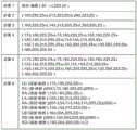
图12F是一个图示出了在(d=1,n=0,h=0)的一个逻辑节点FF,在(d=1,n=0,h=0)的一个逻辑节点FG,在(d=1,n=0,h=0)的一个物理节点KP,在(d=1,n=0,h=0)的一个物理节点KQ,在(d=1,n=0,h=0)的一个物理节点KR,在(d=1,n=0,h=0)的一个物理节点KS,和在(d=1,n=0,h=0)的一个物理节点KT。图12F还示出命名为K1,K2,K11至K18的拓扑-映射,还示出命名为K3至K8的深度-映射,命名为K9和K10的物理拓扑-通路,和命名为K19的一个逻辑拓扑-通路,表示为一个图里的有向边。Figure 12F is a diagram showing a logical node FF at (d=1, n=0, h=0), a logical node FG at (d=1, n=0, h=0), at ( A physical node KP at d=1, n=0, h=0), a physical node KQ at (d=1, n=0, h=0), at (d=1, n=0, h= 0), one physical node KS at (d=1, n=0, h=0), and one physical node KT at (d=1, n=0, h=0). Figure 12F also shows topology-maps named K1, K2, K11 to K18, also a depth-map named K3 to K8, physical topology-paths named K9 and K10, and a logical one named K19 Topology-paths, represented as directed edges in a graph.
图12G是一个图示出了根据图6A的表示法,命名为K3至K8的深度-映射。Figure 12G is a diagram showing depth-maps named K3 to K8 according to the representation of Figure 6A.
图12H是一个图示出了根据图6C的表示法,拓扑-映射K1和K2。Figure 12H is a diagram showing topology-maps K1 and K2 according to the representation of Figure 6C.
图12I是一个图示出了根据图6C的表示法,拓扑-通路K19。Fig. 12I is a diagram showing the topology-path K19 according to the representation of Fig. 6C.
图12J是一个图示出了在步骤1里从节点FE到节点FG命名为K19的拓扑-通路和步骤里命名为K19的拓扑-通路的递归-通路,步骤2至步骤4为计算的中间步骤。Figure 12J is a diagram showing a topology-path named K19 from node FE to node FG in
图12K是一个图示出了交换-标识符用于命名为K11至K19的边。Figure 12K is a diagram showing the exchange-identifiers used for the edges named K11 to K19.
图12L是一个图示出了在(d=0,h=0)的网络,其为物理节点KP,KQ,KR,KS和KT,是在递归-通路里从命名为K19的请求的拓扑-通路的转发指令计算出的,包含一个输入端口,一个输出端口,一组传入边-关系,以及一组传入边-关系里每个边的交换-标识符,和一组传出边-关系,以及一组传出边-关系里的每个边的交换-标识符。Figure 12L is a diagram showing the network at (d=0, h=0), which are the physical nodes KP, KQ, KR, KS and KT, in a recursive-path from a request named K19- The forwarding instruction of the path is calculated to contain an input port, an output port, a set of incoming edge-relations, and a set of exchange-identifiers for each edge in a set of incoming edge-relations, and a set of outgoing edges- relation, and a set of outgoing edges - the exchange-identifier for each edge in the relation.
图13A是一个图示出了一个逻辑节点的FE,一个逻辑节点FF,一个逻辑节点FG,和一个物理节点KP。图13A还示出了从逻辑节点FE到逻辑节点FF的一个拓扑-映射,从逻辑节点FF到逻辑节点FG的一个拓扑-映射,并从逻辑节点FE到物理节点KP的一个深度映射,表示为一个图里的有向边。FIG. 13A is a diagram showing an FE of a logical node, a logical node FF, a logical node FG, and a physical node KP. Figure 13A also shows a topology-mapping from logical node FE to logical node FF, a topology-mapping from logical node FF to logical node FG, and a depth mapping from logical node FE to physical node KP, denoted as A directed edge in a graph.
图13B是一个图示出了在(d=1,n=0,h=0)的一个逻辑节点FE,在(d=1,n=0,h=0)的一个逻辑节点FF和在(d=1,n=0,h=0)的一个逻辑节点FG,在(d=1,n=0,h=0)的一个物理节点KP,在(d=1,n=0,h=0)的一个未知物理节点?X2和在(d=1,n=0,h=0)的一个未知物理节点?X 3。图13B还示出了命名为K1和K2的拓扑-映射,命名为K4至K8的深度-映射和命名为?K9和K10的未知物理拓扑-通路,表示为一个图里的有向边。在图13B里问号表示未知物理节点和未知物理拓扑-通路。FIG. 13B is a diagram showing a logical node FE at (d=1, n=0, h=0), a logical node FF at (d=1, n=0, h=0) and a logical node at ( A logical node FG at d=1, n=0, h=0), a physical node KP at (d=1, n=0, h=0), at (d=1, n=0, h= 0) an unknown physical node? X2 and an unknown physical node at (d=1,n=0,h=0)? X3. Figure 13B also shows topology-maps named K1 and K2, depth-maps named K4 to K8 and named ? Unknown physical topology-paths of K9 and K10, represented as directed edges in a graph. Question marks in Figure 13B indicate unknown physical nodes and unknown physical topology-paths.
图13C是一个图示出了根据图6A的表示法,命名为K4至K8的深度-映射。Figure 13C is a diagram showing depth-maps named K4 to K8 according to the representation of Figure 6A.
图13D是一个图示出了命名为K1的拓扑-映射。Figure 13D is a diagram showing the topology-map named K1.
图13E是一个图示出了命名为K1的拓扑-映射的物理实体,命名为K2的拓扑-映射的物理实体图,和一个搜索声明。Figure 13E is a diagram illustrating a topology-mapped physical entity named K1, a topology-mapped physical entity named K2, and a search statement.
图14A是一个图示出了一个逻辑节点FE,一个逻辑节点FF,一个逻辑节点FG,和一个物理节点KP。图14A还示出逻辑节点FE到逻辑节点FF的一个拓扑-映射,逻辑节点FF到逻辑节点FE的一个拓扑-映射,逻辑节点FF到逻辑节点FG的一个拓扑-映射,逻辑节点FG到逻辑节点FF的一个拓扑-映射,表示为一个图里的有向边。FIG. 14A is a diagram showing one logical node FE, one logical node FF, one logical node FG, and one physical node KP. Fig. 14A also shows a topology-mapping of logical node FE to logical node FF, a topology-mapping of logical node FF to logical node FE, a topology-mapping of logical node FF to logical node FG, logical node FG to logical node A topology-map of FF, represented as directed edges in a graph.
图14B是一个图示出了在(d=1,n=0,h=0)的一个逻辑节点FE,在(d=1,n=0,h=0)的一个逻辑节点FF和在(d=1,n=0,h=0)的一个逻辑节点FG,在(d=0,n=0,h=0)的一个未知物理节点?X1,在(d=0,n=0,h=0)的一个未知物理节点?X2和在(d=0,n=0,h=0)的一个未知物理节点?X 3。图14B还示出了命名为K1,K2,K21和K22的映射-拓扑,命名为K3至K8的深度-映射,和命名为?K9,K10,K23和K24的未知物理拓扑-通路,表示为一个图里的有向边。在图14B里的问号表示未知物理节点和未知物理拓扑-通路。FIG. 14B is a diagram showing a logical node FE at (d=1, n=0, h=0), a logical node FF at (d=1, n=0, h=0) and a logical node at ( A logical node FG at d=1, n=0, h=0), an unknown physical node at (d=0, n=0, h=0)? X1, an unknown physical node at (d=0,n=0,h=0)? X2 and an unknown physical node at (d=0,n=0,h=0)? X3. Figure 14B also shows map-topology named K1, K2, K21 and K22, depth-map named K3 to K8, and named ? Unknown physical topology-paths of K9, K10, K23 and K24, represented as directed edges in a graph. The question marks in Figure 14B represent unknown physical nodes and unknown physical topology-paths.
图14C是一个图示出了根据图6C的表示法,拓扑-映射K21和K22。在图14C中“?K23[拓扑-通路]“表示K23是一个未知拓扑-通路,“?K24[拓扑-通路]”表示K24是一个未知拓扑-通路。Figure 14C is a diagram showing topology-maps K21 and K22 according to the representation of Figure 6C. In Fig. 14C "?K23[topology-path]" indicates that K23 is an unknown topology-path, and "?K24[topology-path]" indicates that K24 is an unknown topology-path.
图14D是一个图示出了命名为K21的一个拓扑-映射。Figure 14D is a diagram showing a topology-map named K21.
图14E是一个图示出了命名为K22的一个拓扑-映射。Figure 14E is a diagram showing a topology-map named K22.
图14F是一个图示出了命名为K1的拓扑-映射的物理实体,命名为K2的拓扑-映射的物理实体,命名为K21的拓扑-映射的物理实体,命名为K22的拓扑-映射的物理实体,和搜索声明。Figure 14F is a diagram showing a topology-mapped physical entity named K1, a topology-mapped physical entity named K2, a topology-mapped physical entity named K21, a topology-mapped physical entity named K22 entities, and search statements.
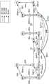
图15A是一个图示出了逻辑节点FE,FF,FG,FH和FJ,拓扑-映射,层-映射和拓扑-通路。Figure 15A is a diagram showing logical nodes FE, FF, FG, FH and FJ, topology-map, layer-map and topology-path.
图15B是一个图示出了在(d=1,n=0,h=0),的逻辑节点FE,FF和FG,和在(d=1,n=1,h=0)的逻辑节点FH和FJ,在(d=0,n=0,h=0)的一个未知物理节点?X1,在(d=0,n=0,h=0)的一个未知物理节点?X2,在(d=0,n=0,h=0)的一个未知物理节点?X 3,在(d=0,n=0,h=0)的一个未知物理节点?X4和在(d=0,n=0,h=0)的一个未知物理节点?X5。图15B还示出了命名为K1和K2的拓扑-映射,命名为K3至K8和K28至K31的深度-映射,命名为K25和K26的逻辑层-映射,命名为?K32和?K33的未知物理层-映射和命名为?K9和K10的未知物理拓扑-通路,表示为一个图里的有向边。在图15B里的问号表示未知物理节点,未知物理层-映射和未知物理拓扑-通路。Figure 15B is a diagram showing logical nodes FE, FF and FG at (d=1, n=0, h=0), and logical nodes at (d=1, n=1, h=0) FH and FJ, an unknown physical node at (d=0,n=0,h=0)? X1, an unknown physical node at (d=0,n=0,h=0)? X2, an unknown physical node at (d=0,n=0,h=0)?
图15C是一个图示出了根据图6A的表示法,命名为K3至K8,和K28至K31的深度-映射。Figure 15C is a diagram showing depth-maps named K3 to K8, and K28 to K31 according to the representation of Figure 6A.
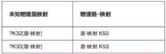
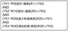
图15D是一个图示出了根据图6C的表示法,拓扑-映射K1,K2和K34,层-映射K25和K26,和拓扑-通路K27和K35。在图15D“?K9[拓扑-通路]'表示K9是一个未知拓扑-通路,“?K10[拓扑-通路]'表示K10是一个未知拓扑-通路,“?K32[层-映射]'表示?K32是一个未知层-映射,以及“?K33[层-映射]'表示?K33是一个未知层-映射。Figure 15D is a diagram showing topology-maps K1, K2 and K34, layer-maps K25 and K26, and topology-pathways K27 and K35 according to the representation of Figure 6C. In Figure 15D "?K9[Topology-Pathway]' indicates that K9 is an unknown Topology-Pathway, "? K10[topology-path]' indicates that K10 is an unknown topology-path, "?K32[layer-map]' indicates that ?K32 is an unknown layer-map, and "? K33[layer-map]' means? K33 is an unknown layer-map.
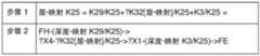
图15E是一个图示出了命名为K25的层-映射。Figure 15E is a diagram showing a layer-map named K25.
图15F是一个图示出了命名为K26的层-映射。Figure 15F is a diagram showing a layer-map named K26.
图15G是一个图示出了了一个命名为K1的拓扑-映射的物理实体,命名为K2的拓扑-映射的物理实体图,命名为K25的层-映射的物理实体,命名为K26的层-映射的物理实体,和一个搜索声明。Figure 15G is a diagram showing a topology-mapped physical entity named K1, a topology-mapped physical entity named K2, a layer named K25-mapped physical entity, a layer named K26- The mapped physical entity, and a search statement.
图16A是一个图示出了由物理节点KE和KK表示的一个第一个计算设备,由物理节点KF表示的一个第一个分组转发系统,由物理节点KH和KL表示的一个第二个计算设备和由物理节点KJ和KM表示的一个第三个计算设备,通过为物理链路的拓扑-映射和层-映射链接。图16A还示出了p211至p218和p221至p226附着点(PoA)。Figure 16A is a diagram showing a first computing device represented by physical nodes KE and KK, a first packet forwarding system represented by physical node KF, a second computing device represented by physical nodes KH and KL The device and a third computing device represented by physical nodes KJ and KM are linked by topology-map and layer-map for physical links. Figure 16A also shows the p211 to p218 and p221 to p226 points of attachment (PoAs).
图16B是一个图示出了在(d=0,n=0,h=0)的物理节点KE,KF,KG,KH和KJ,和在(d=0,n=1,h=0)的物理节点KK,KL和KM。图16B还示出了命名为K41至K48的拓扑-映射和K49至K54的层-映射,表示为一个图里的有向边。Figure 16B is a diagram showing physical nodes KE, KF, KG, KH and KJ at (d=0, n=0, h=0), and at (d=0, n=1, h=0) The physical nodes KK, KL and KM. Figure 16B also shows topology-maps named K41 to K48 and layer-maps K49 to K54, represented as directed edges in a graph.
图16C是一个图示出了根据图6A的表示法,命名为K41至K48的拓扑-映射,和命名为K49至K54的层-映射。Figure 16C is a diagram showing topology-maps named K41 to K48, and layer-maps named K49 to K54, according to the representation of Figure 6A.
图16D是一个图示出了一个未知物理节点是如何相关与一个物理节点。Figure 16D is a diagram showing how an unknown physical node is related to a physical node.
图16E是一个图示出了一个未知物理拓扑-通路是如何相关与一个物理拓扑-通路。Figure 16E is a diagram showing how an unknown physical topology-path is related to a physical topology-path.
图16F是一个图示出了一个未知物理层-映射是如何相关与一个物理层-映射。Figure 16F is a diagram showing how an unknown physical layer-mapping is related to a physical layer-mapping.
图16G是一个图示出了根据图6A的表示法,命名为K3至K8,和K28至31的深度映射。Figure 16G is a diagram showing depth maps named K3 to K8, and K28 to 31 according to the representation of Figure 6A.
图16H是一个图示出了根据图6C的表示法,拓扑-映射K1和K2和层-映射K25和K26。Figure 16H is a diagram showing topology-maps K1 and K2 and layer-maps K25 and K26 according to the representation of Figure 6C.
图16I是一个图示出了在d=1,n=0,h=0)的逻辑节点FE,FF和FGD,在(d=1,n=1,h=0)的逻辑节点FH和FJ,在(d=0,n=1,h=0)的物理节点KE,KF,KG,KH,KJ,和在(d=0,n=1,h=0)的物理节点KK,KL和KM。图16I还示出了命名为K1,K2,K41至K48的拓扑-映射,命名为K3至K8和K28至K31的深度-映射,命名为K25,K26和K49至K54的层-映射,和命名为K9和K10的物理拓扑-通路,表示为一个图里的有向边。Figure 16I is a diagram showing logical nodes FE, FF and FGD at d=1, n=0, h=0), and logical nodes FH and FJ at (d=1, n=1, h=0) , at (d=0, n=1, h=0) physical nodes KE, KF, KG, KH, KJ, and at (d=0, n=1, h=0) physical nodes KK, KL and KM. Figure 16I also shows topology-maps named K1, K2, K41 to K48, depth-maps named K3 to K8 and K28 to K31, layer-maps named K25, K26 and K49 to K54, and named is the physical topology-path of K9 and K10, represented as a directed edge in a graph.
图16J是一个图示出了在(d=1,n=0,h=0)的逻辑节点FE,FF和FG,在(d=1,n=1,h=0)的逻辑节点FH和FJ,在(d=0,n=0,h=0)的物理节点KE,KF,KG,KH,KJ,和在(d=0,n=1,h=0)的物理节点KK,KL和KM。图16J还示出了命名为K1,K2,K41至K48的拓扑-映射,命名为K3至K8和K28至h K31的深度-映射,命名为K25,K26和K49至K54的层-映射,和命名为K9,K10,K27和K35的拓扑-通路,表示为一个图里的有向边。Figure 16J is a diagram showing logical nodes FE, FF and FG at (d=1, n=0, h=0), logical nodes FH and FG at (d=1, n=1, h=0) FJ, physical nodes KE, KF, KG, KH, KJ at (d=0, n=0, h=0), and KK, KL at (d=0, n=1, h=0) and KM. Figure 16J also shows topology-maps named K1, K2, K41 to K48, depth-maps named K3 to K8 and K28 to h K31, layer-maps named K25, K26 and K49 to K54, and Topological-pathways named K9, K10, K27 and K35 are represented as directed edges in a graph.
图17A是一个图示出了示出在步骤1里的命名为K35的一个请求的拓扑-通路,并且在步骤6里的命名为K35请求的拓扑-通路中的递归-通路,步骤2至步骤5是计算的中间步骤。Figure 17A is a diagram showing a recursive-path in a topology-path named K35 requested in
图17B是一个图示出了从命名为K35的请求的拓扑-通路计算出在递归-通路里的物理节点KE,KF,KG,KJ,KK和KM的转发指令包括一个输入端口,一个输出端口,一组传入边-关系和一组传出边-关系。Figure 17B is a diagram showing that the forwarding instructions for physical nodes KE, KF, KG, KJ, KK and KM in the recursive-path calculated from the topology-path of the request named K35 include one input port, one output port , a set of incoming edge-relations and a set of outgoing edge-relations.
图17C是一个图示出了交换-标识符,用于命名为K41至K48,K27和K35的边。Figure 17C is a diagram showing exchange-identifiers for edges named K41 to K48, K27 and K35.
图17D是一个图示出了从命名为K35的请求的拓扑-通路计算出在递归-通路里的物理节点KE,KF,KG,KJ,KK和KM的转发指令包括一个输入端口,一个输出端口,一组传入边-关系和一组传入边-关系里的每个边的交换-标识符,以及一组传出边-关系和一组传出边-关系里的每个边的交换-标识符。Figure 17D is a diagram showing that the forwarding instructions for physical nodes KE, KF, KG, KJ, KK and KM in the recursive-path calculated from the topology-path of the request named K35 include one input port, one output port , a set of incoming edge-relations and an exchange-identifier for each edge in a set of incoming edge-relations, and a set of outgoing edge-relations and a set of outgoing edge-relationships for each edge in the relationship - Identifier.
图17E是一个图示出了交换-标识符,用于命名为K41至K48,K27和K35的边。Figure 17E is a diagram showing exchange-identifiers for edges named K41 to K48, K27 and K35.
图17F是一个图示出了是具有逻辑名URI-1的用户代理的逻辑节点FH,具有逻辑名URI-2的源服务器的逻辑节点FJ,命名为K34的拓扑-映射,和命名为K35的拓扑-映射表示“HTTP请求1“。Figure 17F is a diagram showing the logical node FH which is the user agent with the logical name URI-1, the logical node FJ which is the origin server with the logical name URI-2, the topology-map named K34, and the logical node named K35 Topology-map means "
图17G是一个图示出了物理节点KE,KF,KG,KH,KJ,KK,KL和KM,在递归-通路里从命名为K35的请求的拓扑-通路的转发指令计算出的,包含一个输入端口,一个输出端口,一组传入边-关系,以及一组传入边-关系里每个边的交换-标识符,和一组传出边-关系,以及一组传出边-关系里的每个边的交换-标识符。Figure 17G is a graph showing physical nodes KE, KF, KG, KH, KJ, KK, KL, and KM, computed from the forwarding instructions of the topology-path of the request named K35 in the recursive-path, including a An input port, an output port, a set of incoming edge-relations, and a set of exchange-identifiers for each edge in a set of incoming edge-relations, and a set of outgoing edge-relations, and a set of outgoing edge-relationships exchange-identifier for each edge in .
图18A是一个图示出了在(d=0,n=0,h=0)的物理节点KP,KQ,KR,KS,KT,命名为K11至K18的拓扑-映射,和命名为K55至K60的层-映射,表示为一个图里的有向边。FIG. 18A is a diagram showing the topology-maps of physical nodes KP, KQ, KR, KS, KT, named K11 to K18, and named K55 to K18 at (d=0, n=0, h=0) Layer-map of K60, represented as directed edges in a graph.
图18B是根据图6A的表示法,命名为K55至K60的层-映射的一个图。Figure 18B is a diagram of the layer-maps named K55 to K60 according to the representation of Figure 6A.
图18C是一个图示出了一个未知物理节点是如何相关与一个物理节点。Figure 18C is a diagram showing how an unknown physical node is related to a physical node.
图18D是一个图示出了一个未知物理拓扑-通路是如何相关与一个物理拓扑-通路。Figure 18D is a diagram showing how an unknown physical topology-path is related to a physical topology-path.
图18E是一个图示出了一个未知物理层-映射是如何相关与一个物理层-映射。Figure 18E is a diagram showing how an unknown physical layer-mapping is related to a physical layer-mapping.
图19A是一个图示出了在(d=1,n=0,h=0)的逻辑节点FE,FF和FG,在(d=1,n=1,h=0)的逻辑节点FH和FJ和在(d=0,n=0,h=0)的未知物理节点?X1,?X2,?X 3。图19A还示出了命名为K1和K2的拓扑-映射,命名为K3至K8,K37至K38的深度-映射,命名为K25K26的逻辑层-映射,命名为?K39和?K40的未知物理层-映射和命名为?K9和K10的未知物理拓扑-通路,表示为一个图里的有向边。在图19A里的问号表示未知物理节点,未知物理层-映射和未知物理拓扑-通路。Figure 19A is a diagram showing logical nodes FE, FF and FG at (d=1, n=0, h=0), and logical nodes FH and FG at (d=1, n=1, h=0) FJ and unknown physical node at (d=0,n=0,h=0)? X1, ? X2, ? X3. Figure 19A also shows topology-maps named K1 and K2, named K3 to K8, depth-maps of K37 to K38, named K25K26 logical layer-map named ? K39 and ? Unknown physical layer for K40 - mapped and named? Unknown physical topology-paths of K9 and K10, represented as directed edges in a graph. The question marks in Figure 19A represent unknown physical nodes, unknown physical layer-maps and unknown physical topology-paths.
图19B是一个图示出了根据图6A中的表示法,命名为K3至K8,和K37至K38的深度映射。Figure 19B is a diagram showing depth maps named K3 to K8, and K37 to K38 according to the representation in Figure 6A.
图19C是一个图示出了根据图6C的表示法,命名为K1和K2的拓扑-映射,命名为K25在层降低的一个层-映射,命名为K26在层增加的一个层-映射。Figure 19C is a diagram showing topology-maps named K1 and K2, a layer-mapping named K25 in layer-decreasing, and a layer-mapping named K26 in layer-increasing, according to the representation of Figure 6C.
图19D是一个图示出了命名为K25的层-映射。Figure 19D is a diagram showing a layer-map named K25.
图19E是一个图示出了命名为K26的层-映射。Figure 19E is a diagram showing a layer-map named K26.
图19F是一个图示出了一个搜索声明。Figure 19F is a diagram showing a search statement.
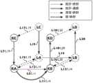
图20是一个图示出了网络KA,KB,KC,KD,LA,LB,LC,LD和命名为L5,L14和L22的拓扑-映射,命名为L12,L13,L15,L16,L17和L18的深度-映射,命名为L7,L10,L19和L20层-映射和命名为L11,L21和L23的拓扑-通路,和边-关系。Figure 20 is a diagram showing the topology-maps of networks KA, KB, KC, KD, LA, LB, LC, LD and named L5, L14 and L22, named L12, L13, L15, L16, L17 and L18 The depth-maps, named L7, L10, L19 and L20 layers-maps and named L11, L21 and L23 topology-paths, and edge-relations.
图21A是一个图示出了物理节点KX,KY和逻辑节点LA,LB,LC,LD和命名的拓扑-映射,层-映射和深度-映射。Figure 21A is a diagram showing the topology-map, layer-map and depth-map of physical nodes KX, KY and logical nodes LA, LB, LC, LD and naming.
图21B是一个图示出了物理节点KX,KY和逻辑节点LA,LB,LC,LD和命名的拓扑-映射,层-映射和深度-映射。Figure 21B is a diagram showing the topology-map, layer-map and depth-map of physical nodes KX, KY and logical nodes LA, LB, LC, LD and naming.
发明的优选实施例的详细描述DETAILED DESCRIPTION OF THE PREFERRED EMBODIMENTS OF THE INVENTION
非预公布的现有技术的PCT/EP2014/055640描述了一个软件定义网络(SDN)的编译器的方法。以下所述方法的主要元件的概要说明。然而,应该注意的是在PCT/EP2014/0055640已描述的所有特征也可在本发明中应用。还有PCT/EP2014/0055640里描述的特征/实施例的组合,没有在此被明确描述,也是在本发明的范围内可能的实施例。因此,PCT/EP2014/0055640的所有段落在下文通过参照的方式在本文件中并入。Non-pre-published prior art PCT/EP2014/055640 describes a software-defined networking (SDN) compiler approach. A summary description of the main elements of the method described below. However, it should be noted that all the features that have been described in PCT/EP2014/0055640 are also applicable in the present invention. Also combinations of features/embodiments described in PCT/EP2014/0055640, which are not explicitly described here, are also possible embodiments within the scope of the present invention. Accordingly, all paragraphs of PCT/EP2014/0055640 are hereby incorporated by reference in this document.
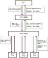
如在上面给出的介绍中SDN的定义,导致了本发明至一个系统包含以下组件如图1里描述(参照PCT/EP2014/055640图1,35页)。The definition of SDN, as in the introduction given above, leads to the invention into a system comprising the following components as described in Figure 1 (cf. PCT/EP2014/055640 Figure 1, page 35).
1.一个用户在一个高层次网络规范里定义一个网络。1. A user defines a network in a high-level network specification.
2.一个SDN编译器转换高层次网络规范成一组物理和虚拟网络以及计算资源的指令。2. An SDN compiler converts high-level network specifications into a set of physical and virtual network and computing resource instructions.
3.一个SDN控制器分配这组指令与物理和虚拟网络以及计算资源。3. An SDN controller distributes the set of instructions with physical and virtual network and computing resources.
4.物理和虚拟联网以及计算资源在一个传入分组上按照收到的一组指令执行行动。在图1中,它们用术语“SDN节点”被表示。4. Physical and virtual networking and computing resources perform actions on an incoming packet in accordance with a received set of instructions. In Figure 1, they are denoted by the term "SDN node".
在上面第1点提到的一个用户可能是,但不限于,一个人,一个网络管理系统,云计算管理系统,应用程序,另一个SDN编译器。这样,一个用户可以指“用户设备”,即,任何合适的计算机设备,如计算机工作站,可能是独立的或更大的网络的一部分。这样的计算机设备的一个例子示于图10和将在以下描述。A user mentioned in
在图1中,从底部到顶部的方向,各个部件在北向接口上报告已执行的特定任务以及报告变化,统计信息和差错。In Figure 1, from the bottom to the top direction, the various components report on the northbound interface specific tasks performed as well as changes, statistics and errors.
在第4点所提到的资源包括典型的组网和计算资源,但不限于:The resources mentioned in
·物理分组转发装置(如,但不限于,第2层交换机,第3层路由器,防火墙,深度分组检测设备,缓存节点,或其他类型的中间组件)。• Physical packet forwarding devices (such as, but not limited to,
·充当网络主机的物理设备,例如但不限于物理服务器,个人计算机,笔记本电脑,平板电脑,移动电话,A physical device that acts as a network host, such as, but not limited to, physical servers, personal computers, laptops, tablets, mobile phones,
·物理网络接口卡(NIC),a physical network interface card (NIC),
·虚拟物理服务器里的虚拟交换机,Virtual switches in virtual physical servers,
·虚拟物理服务器里的虚拟机,Virtual machines in virtual physical servers,
·虚拟网络接口卡(NIC),Virtual Network Interface Cards (NICs),
·支持IPv4的路由器,支持IPv6的路由器,MPLS-交换机[MPLS=多协议标签交换],应用程序过程提供的分组-交换,IPv4-capable routers, IPv6-capable routers, MPLS-switches [MPLS = Multiprotocol Label Switching], packet-switching provided by application processes,
·电路-交换节点作为一个例子,但不限于,光纤交叉-连接交叉连接光纤,远程光分/插多路复用器(ROADM)或光交叉连接交叉连接光波长,同步数字系列(SDH)多路复用器或同步光网络(SONET)多路复用交叉连接时隙,Circuit-switched nodes as an example, but not limited to, fiber optic cross-connect cross-connect fiber, remote optical add/drop multiplexer (ROADM) or optical cross-connect cross-connect optical wavelength, Synchronous Digital Hierarchy (SDH) and more Multiplexer or Synchronous Optical Network (SONET) multiplexing cross-connect time slots,
·OS(操作系统)内核,OS (operating system) kernel,
·应用过程,application process,
·物理或虚拟节点的输入缓冲器和输出缓冲器,input buffers and output buffers for physical or virtual nodes,
·存储设备,作为一个例子,但不限于,支持通过以太网的光纤通道(FCoE)支持通过IP的光纤通道(FCIP)的存储设备,Storage devices, as an example, but not limited to, storage devices that support Fibre Channel over Ethernet (FCoE) that support Fibre Channel over IP (FCIP),
·一个波分多路复用(WDM)的多路复用器,a wavelength division multiplexing (WDM) multiplexer,
在每个上述层次中的物理和/或虚拟节点是分组-交换或电路-交换节点,两者任一。对于这两者分组-交换节点以及电路-交换节点的一组指令是由SDN编译器创建的。在分组-交换节点的情况下,这些指令包括转发表项。在电路-交换节点的情况下,这些指令包括交叉连接的设置。The physical and/or virtual nodes in each of the aforementioned layers are packet-switched or circuit-switched nodes, either. A set of instructions for both packet-switched nodes and circuit-switched nodes is created by the SDN compiler. In the case of packet-switched nodes, these instructions include forwarding entries. In the case of circuit-switched nodes, these instructions include cross-connect settings.
注意,以上提到的资源包括物理设备的组件,例如但不限于一个物理网络接口卡(NIC)和整个物理设备,例如但不限于一个物理分组转发设备。因此,在第4点所指一组指令,可为一个物理设备的一个组件或为整个物理设备创建的。Note that the above-mentioned resources include components of a physical device, such as, but not limited to, a physical network interface card (NIC) and an entire physical device, such as, but not limited to, a physical packet forwarding device. Therefore, the set of instructions referred to in
注意,虚拟节点,代表虚拟资源诸如虚拟机在方法里表示为物理节点(参见PCT/EP2014/055640 186页)。Note that virtual nodes, representing virtual resources such as virtual machines, are represented in the method as physical nodes (see PCT/EP2014/055640 page 186).
一个逻辑网络抽象的规范是由用户输入的“高层次网络规范“,并在上述第1点提及。理想的是,这规范指定任意的逻辑网络,其中包括在任意拓扑里任意数量的逻辑节点,被映射到任意物理以及虚拟网络和计算资源的逻辑节点。多个逻辑网络可以被定义并在相同的物理以及虚拟网络和计算资源上同时创建。The specification of a logical network abstraction is the "high-level network specification" entered by the user and mentioned in
上述第2点指的是“高层次网络规范翻译成一组网络和计算资源的指令”。在一个分组转发交换机的情况下,这些指令是交换机根据转发分组的转发表项。在一台主机的情况下,这些指令是哪些分组应该被接受或丢弃根据的过滤表项和到哪个输出端口发送始发于该主机节点到特定目的节点的分组的指令。在一个网络接口卡(NIC)的情况下,这些指令是哪些分组应该被转发或丢弃根据的过滤器表项。上面提到的第2点提供了从一个高层次的网络规范到适当的物理和虚拟网络和计算资源的一组指令的翻译或编译。我们称这个过程为一个“SDN编译器“过程,类似计算中使用的编译器,翻译一个高层次的语言到层次指令。请注意,上述过程应当对两者物理以及虚拟网络和计算资源提供指令,而相比与所谓“重叠“虚拟网络(如提出的例如Nicira/VMWare),其基本上在物理网络之上创建一个虚拟隧道,除了在隧道入口和出口交换机外,没有配置物理交换机。所希望的SDN编译器的方法应该提供一个整体的方式既包括两者虚拟和物理资源,包括整个物理网络。此外,所希望的SDN编译方法还应该指示非交换网络设备,与上面提到的,所需的指令。此外,由于当前的OpenFlow的实现提供在软件(例如Open vSwitch提供在虚拟物理服务器中运行的虚拟交换机),以及在硬件(例如NEC ProgrammableFlow PF5240交换机),有必要确定跨越虚拟和物理网络和计算资源的前述指令。在一个实现中,“SDN编译器“的功能,或至少一部分功能,和“SDN控制器”的功能,或至少一部分功能,可以合并成一个单个的系统。
现在,我们首先将描述物理和虚拟资源,为其SDN编译器使用功能表示法创建相应的指令。图2A,2B,2C和2D(参照PCT/EP2014/055640 37页图2A,2B,2F,2G)描绘了一个物理网络的组成部分。物理节点的例子在图2A示出和其被认为在其上创建逻辑网络的物理资源。作为物理节点(在图2A BD至BA)的命名是只是用于识别物理资源,而不是用于在决策任何转发。如在图2B中所描述的,我们定义一个物理网络(在图2B标识为BAA)是物理节点的集合。物理节点通过物理链路(由实线表示)相互连接的。Now, we will first describe physical and virtual resources, creating corresponding instructions using functional notation for their SDN compiler. Figures 2A, 2B, 2C and 2D (see Figures 2A, 2B, 2F, 2G on page 37 of PCT/EP2014/055640) depict the components of a physical network. An example of a physical node is shown in Figure 2A and it is considered a physical resource on which a logical network is created. The nomenclature as physical nodes (BD to BA in Figure 2A) is only used to identify the physical resource, not to be used in making any forwarding decisions. As depicted in Figure 2B, we define a physical network (identified as BAA in Figure 2B) as a collection of physical nodes. The physical nodes are connected to each other by physical links (represented by solid lines).
一个物理链路是双向的情况下,一个物理链路在一对物理节点之间创建一对邻接,每个方向一个邻接。一个物理链路是单向的情况下,一个物理链路在一对物理节点之间创建一个邻接,一个方向的一个邻接。该物理链路可以是任何物理介质,包括但不限于,光纤电缆,铜电缆,空气。物理链路也可以是由其他的网络技术提供的通路,例如但不限于光波长,时分多路复用(TDM)电路,多协议标签交换(MPLS)。一组物理节点与一组物理链路的组合确定网络的物理拓扑。物理网络可以包含任意数量的节点,具有任意链路,导致于一个任意拓扑。When a physical link is bidirectional, a physical link creates a pair of adjacencies between a pair of physical nodes, one adjacency in each direction. In the case where a physical link is unidirectional, a physical link creates an adjacency between a pair of physical nodes, one adjacency in one direction. The physical link can be any physical medium including, but not limited to, fiber optic cable, copper cable, air. Physical links may also be pathways provided by other network technologies, such as, but not limited to, optical wavelengths, time division multiplexing (TDM) circuits, multiprotocol label switching (MPLS). The combination of a set of physical nodes and a set of physical links determines the physical topology of the network. A physical network can contain any number of nodes, with any link, resulting in an arbitrary topology.
一个典型的物理网络示出在图2C,示出了物理网络BAA以及BA至BD的物理节点。如在图2C中所描述,物理节点和物理链路之间的接口被称为物理附着点(POA),为p101至p108表示。一个典型的附着点(PoA)的标识符的例子是在目前部署的网络的以太网媒体接入控制(MAC)的地址,但我们的发明并不限于此。附着点(PoA)的标识符在SDN的控制下的网络集合里必须是独特的。附着点(PoA)识别两者,一个节点的“输入端口”当节点接收分组或信号时以及一个节点的“输出端口”当节点发送分组或信号时。如在图2C中所描绘的,每个物理链路具有一个或更多个成本类型和在每个方向的每个成本类型相关的(多个)成本值。在物理网络中使用的一个典型的成本类型是链路延迟,其中通常以毫秒表示的成本值,但任何类型的成本,可以使用表示所述链路的属性。每个双向物理链路具有两个成本值,每个方向一个。每个单向物理链路的成本类型具有一个成本值。在特定方向的物理链路的成本值示出了起源分组在那个特定方向最靠近的物理节点。例如,从BA至BB的链路有一个为1的成本值。从BB到B A的链路有一个为3的成本值。当一个物理链路表示一对物理节点之间的邻接-关系(多个),一个物理通路表示从一个物理源节点到一个物理目的节点,一个分组或信号的一个物理路线,这在单播网络的情况下。在多播或广播网络的情况下,单个的物理源节点和多个物理目的节点之间有一个物理-通路的关系。然后,一个物理节点通过一个深度-映射映射到多于一个的逻辑节点导致多播。物理-通路可以在每个方向有多个成本类型,通常一个成本值等于在特定的方向的物理-链路包括的特定成本类型的成本值的总和。一个物理-通路是分组从源节点到目的节点通过的物理附着点(PoA)的序列。“通路”另一选择术语是“流”,例如在OpenFlow的规范使用术语“流“(Flow)。A typical physical network is shown in Figure 2C, showing the physical network BAA and the physical nodes BA to BD. As depicted in Figure 2C, the interface between a physical node and a physical link is called a physical point of attachment (POA), denoted p101 to p108. An example of a typical Point of Attachment (PoA) identifier is the Ethernet Media Access Control (MAC) address in currently deployed networks, but our invention is not so limited. The identifier of the Point of Attachment (PoA) must be unique within the set of networks under the control of the SDN. The Point of Attachment (PoA) identifies both, a node's "input port" when the node receives packets or signals and a node's "output port" when the node sends packets or signals. As depicted in Figure 2C, each physical link has one or more cost types and cost value(s) associated with each cost type in each direction. A typical type of cost used in physical networks is link latency, where the cost value is usually expressed in milliseconds, but any type of cost can be represented using the attributes of the link. Each bidirectional physical link has two cost values, one for each direction. The cost type for each unidirectional physical link has a cost value. The cost value of a physical link in a particular direction shows the closest physical node that originated the packet in that particular direction. For example, the link from BA to BB has a cost value of 1. The link from BB to B A has a cost value of 3. When a physical link represents an adjacency-relationship (plurality) between a pair of physical nodes, a physical path represents a physical route from a physical source node to a physical destination node, a packet or signal, which in unicast networks in the case of. In the case of a multicast or broadcast network, there is a physical-path relationship between a single physical source node and multiple physical destination nodes. Then, a physical node is mapped to more than one logical node through a depth-map resulting in multicast. A physical-path can have multiple cost types in each direction, usually a cost value is equal to the sum of the cost values of a specific cost type included in a physical-link in a specific direction. A physical-path is a sequence of physical points of attachment (PoAs) through which packets travel from a source node to a destination node. Another alternative term for "path" is "flow", eg in the specification of OpenFlow the term "Flow" is used.
我们也可以用一个有向图作为网络代表。所述有向图可被加权。图2D给出网络BAA的有向图,示出顶点(节点)BA到BD与连接顶点的有向边。在图2D中,“边”,是用箭头连接一个顶点与另外一个顶点来表示,其中箭头方向表示数据流的方向。当作为一个有向图来表示,两个顶点之间的双向物理链路是由两个边来表示的。每个边对应于一个邻接。We can also use a directed graph as a network representation. The directed graph can be weighted. Figure 2D presents a directed graph of the network BAA, showing vertices (nodes) BA to BD with directed edges connecting the vertices. In Figure 2D, an "edge" is represented by an arrow connecting one vertex to another vertex, where the direction of the arrow indicates the direction of data flow. When represented as a directed graph, a bidirectional physical link between two vertices is represented by two edges. Each edge corresponds to an adjacency.
PCT/EP2014/055640(39,41,42页)根据术语通常用法描述了属性属于一个物理交换节点,一个物理主机节点,一个物理网络接口卡(NIC),一个虚拟交换节点和一个虚拟主机节点。一个例子是,但不限于,一个主节点是计算设备或一个存储设备(参照PCT/EP2014/055640 155和204页)。PCT/EP2014/055640 (pages 39, 41, 42) describes attributes belonging to a physical switch node, a physical host node, a physical network interface card (NIC), a virtual switch node and a virtual host node, according to common usage of the term. An example, but not limited to, is that a master node is a computing device or a storage device (cf. PCT/EP2014/055640 pages 155 and 204).
到现在为止,我们提供了物理和虚拟网络以及计算资源的功能模型。现在,以说明本发明,我们认为,一个高层次规范可以定义一个逻辑网络并且独立于物理和虚拟资源。Until now, we have provided functional models of physical and virtual networks and computing resources. Now, to illustrate the present invention, we consider that a high-level specification can define a logical network and is independent of physical and virtual resources.
逻辑网络是通过指定定义的:A logical network is defined by specifying:
1.逻辑网络的命名1. Naming of logical networks
2.其中逻辑网络包括的逻辑节点命名2. The logical nodes included in the logical network are named
3.逻辑节点之间的邻接3. Adjacency between logical nodes
4.逻辑网络中的一个或更多个成本类型4. One or more cost types in a logical network
5.逻辑节点之间的逻辑邻接的每个成本类型的成本(多数)5. Cost per cost type for logical adjacency between logical nodes (majority)
6.逻辑网络的转发策略6. Forwarding strategy of logical network
7.从物理和/或虚拟节点到逻辑节点的映射7. Mapping from physical and/or virtual nodes to logical nodes
成本类型和值表示链接的属性,并且可以被用为确定一个转发策略。The cost type and value represent attributes of the link and can be used to determine a forwarding strategy.
如上所述的物理和/或虚拟节点被映射到逻辑节点,使用一个1:1,1:N或N:1映射,如下:Physical and/or virtual nodes as described above are mapped to logical nodes using a 1:1, 1:N or N:1 mapping as follows:
‐1:1物理到逻辑映射‐1:1 physical to logical mapping
‐1:N物理到逻辑映射‐1:N physical to logical mapping
‐N:1物理到逻辑映射‐N: 1 physical to logical mapping
‐1:1虚拟到逻辑映射‐1:1 virtual to logical mapping
‐1:N虚拟逻辑映射‐1:N virtual logical map
‐N:1虚拟到逻辑映射‐N: 1 virtual to logical mapping
‐N:1物理和虚拟到逻辑映射‐N: 1 physical and virtual to logical mapping
如上所述,在这方法虚拟节点被表示为物理节点(参见PCT/EP2014/055640 186页),以减少上面的映射:As mentioned above, in this method virtual nodes are represented as physical nodes (see PCT/EP2014/055640 page 186) to reduce the above mapping:
‐1:1物理到逻辑映射‐1:1 physical to logical mapping
‐1:N物理到逻辑映射‐1:N physical to logical mapping
‐N:1物理到逻辑映射‐N: 1 physical to logical mapping
逻辑节点的功能表示为虚线圆圈,如图3C中描绘。一个物理/虚拟到逻辑映射可以具有一个可选成本值用于映射的每个方向。The functions of logical nodes are represented as dashed circles, as depicted in Figure 3C. A physical/virtual to logical mapping can have an optional cost value for each direction of the mapping.
SDN编译器的用户定义逻辑网络。用户可以是,但不限于,一个人,一个网络管理系统,一个云管理系统,一个应用程序,另一个SDN编译器。逻辑网络可以包含任意数量的逻辑节点,具有任意逻辑邻接,导致任意的逻辑拓扑。作为一个例子逻辑网络可以被指定为在一个高层次编程语言里的一个图,其中逻辑节点映射与物理和/或虚拟节点为每个逻辑节点的属性。User-defined logical network for the SDN compiler. A user can be, but is not limited to, a person, a network management system, a cloud management system, an application, another SDN compiler. A logical network can contain any number of logical nodes, with any logical adjacency, resulting in any logical topology. As an example a logical network can be specified as a graph in a high-level programming language, where logical nodes are mapped with physical and/or virtual nodes as attributes of each logical node.
对于逻辑节点,我们使用一个独立于物理和虚拟资源的命名空间的逻辑命名空间。逻辑网络现在可以被定义在逻辑节点方面,其可以以任何适当的形式的任何适当的数目的独特字符来表示,并根据需要被映射到相应的虚拟和物理资源。通过改变该映射,逻辑网络可以重新映射到其他虚拟和物理资源。For logical nodes, we use a logical namespace that is separate from the namespaces of physical and virtual resources. A logical network can now be defined in terms of logical nodes, which can be represented by any suitable number of unique characters in any suitable form, and mapped to corresponding virtual and physical resources as needed. By changing this mapping, logical networks can be remapped to other virtual and physical resources.
1:N物理到逻辑映射允许命名一个物理资源为多个逻辑命名。The 1:N physical-to-logical mapping allows naming one physical resource for multiple logical names.
1:N虚拟到逻辑映射允许命名一个虚拟资源与多个逻辑命名。请注意,逻辑网络是独立于物理网络和虚拟资源,当然具有物理和虚拟资源之间存在一个通路的约束,因此提供了物理网络和虚拟资源的抽象。1:N virtual to logical mapping allows naming a virtual resource with multiple logical names. Note that logical networks are independent of physical networks and virtual resources, and of course have the constraint that there is a path between physical and virtual resources, thus providing an abstraction of physical networks and virtual resources.
逻辑节点命名被使用于转发决定(参见PCT/EP2014/055640 47页)。请注意,逻辑节点是本身被命名,而不是它的接口。在与物理网络类比,我们定义一个逻辑网络是逻辑节点的集合。逻辑节点通过逻辑链接(由实线表示)相互连接的。在一个逻辑链路是双向的情况下,一个逻辑链路创建一对逻辑节点之间的一对邻接。在一个逻辑链路是单向的情况下,逻辑链路创建一对物理节点之间的单个邻接。一组逻辑节点与一组逻辑链路的组合确定网络的逻辑拓扑。在单播网络的情况下,当逻辑链路表示一对逻辑节点之间的邻接-关系(多个),一个逻辑通路表示一个分组跟随的从逻辑源节点到逻辑目的节点的逻辑路线。在多播或广播网络的情况下,单个的逻辑源节点和多个逻辑目的节点之间有一个逻辑通路的关系。一个逻辑通路是分组从逻辑源节点到逻辑目的节点通过的物理附着点(PoA)和/或虚似附着点(PoA)的一个序列。在这里,我们到达一个重要的关系:逻辑源和逻辑目的节点与用于在物理和虚拟附着点(PoA)方面描写的一个通路的关系。这将允许我们用逻辑节点命名定义一个网络和翻译(编译)所定义的网络到为物理和/或虚拟网络和/或计算资源的在物理和/或虚拟附着点(PoA)方面的指令。Logical node naming is used for forwarding decisions (see PCT/EP2014/055640 page 47). Note that the LN itself is named, not its interface. In analogy with a physical network, we define a logical network as a collection of logical nodes. Logical nodes are connected to each other by logical links (represented by solid lines). Where a logical link is bidirectional, a logical link creates a pair of adjacencies between a pair of logical nodes. Where a logical link is unidirectional, the logical link creates a single adjacency between a pair of physical nodes. The combination of a set of logical nodes and a set of logical links determines the logical topology of the network. In the case of a unicast network, when a logical link represents an adjacency-relationship(s) between a pair of logical nodes, a logical path represents a logical route followed by a packet from a logical source node to a logical destination node. In the case of a multicast or broadcast network, there is a logical path relationship between a single logical source node and multiple logical destination nodes. A logical path is a sequence of physical points of attachment (PoAs) and/or virtual points of attachment (PoAs) through which packets pass from a logical source node to a logical destination node. Here, we arrive at an important relationship: the relationship of logical source and logical destination nodes to a path for delineation in terms of physical and virtual points of attachment (PoAs). This will allow us to define a network with logical node names and translate (compile) the defined network to instructions in terms of physical and/or virtual points of attachment (PoAs) for physical and/or virtual networks and/or computing resources.
一个逻辑网络可以创建于一个物理网络,一个虚拟网络或一个物理/虚拟网络的组合(参照PCT/EP2014/055640 93页)。另外,一个逻辑网络可以创建于另一个逻辑网络。为了避免任何含糊,以下我们将指在深度d的一个网络是创建于在深度(d-1)的一个网络。我们指在一个特定深度为深度d,其中d是一个从0(零)开始的正整数。到目前为止,称深度d=0是等于一个物理或虚拟网络。到目前为止称深度d>=1等于一个逻辑网络。组合的物理和虚拟网络是由一个或更多个层组成(参照PCT/EP2014/055640 91页)。在每一层的节点可以通过物理和/或虚拟链路互连。物理链路可以是任何物理介质,包括但不限于,光纤电缆,铜电缆,空气。物理链路也可以是由其他的网络技术提供的通路,例如但不限于光波长,时分多路复用(TDM)电路,一个多协议标签交换(MPLS)。物理链路也可以是由其他的网络技术提供的一个隧道,例如但限于一个GRE隧道[GRE=通用路由封装],NVGRE-隧道[NVGRE=网络虚拟化使用通用路由封装],VXLAN隧道[VXLAN=虚拟可扩展局域网]。虚拟链路可以是一个虚拟连接,包括但不限于虚拟交换机和虚拟机之间的虚拟链路,虚拟机之间的虚拟链路,网络套接字之间的虚拟链路。一个层可能提供服务到一个更高层,并可能从一个低层消费服务。最低分组-交换层提供用于媒体-访问控制(MAC)。一个逻辑网络包括一个或更多个层。A logical network can be created from a physical network, a virtual network or a combination of physical/virtual networks (cf. PCT/EP2014/055640 page 93). Additionally, a logical network can be created from another logical network. To avoid any ambiguity, below we will refer to a network at depth d as a network created at depth (d-1). We refer to a particular depth as depth d, where d is a positive integer starting from 0 (zero). So far, the depth d=0 is said to be equal to a physical or virtual network. So far the depth d>=1 is said to be equal to a logical network. The combined physical and virtual network is composed of one or more layers (cf. PCT/EP2014/055640 page 91). Nodes at each layer can be interconnected by physical and/or virtual links. The physical link can be any physical medium including, but not limited to, fiber optic cable, copper cable, air. Physical links may also be pathways provided by other network technologies, such as but not limited to optical wavelengths, time division multiplexing (TDM) circuits, a multiprotocol label switching (MPLS). The physical link can also be a tunnel provided by other network technologies, such as but limited to a GRE tunnel [GRE=Generic Routing Encapsulation], NVGRE-tunnel [NVGRE=Network Virtualization Using Generic Routing Encapsulation], VXLAN Tunnel [VXLAN= Virtual Extensible Local Area Network]. A virtual link may be a virtual connection, including but not limited to a virtual link between a virtual switch and a virtual machine, a virtual link between virtual machines, and a virtual link between network sockets. A layer may provide services to a higher layer and may consume services from a lower layer. The lowest packet-switching layer is provided for Media-Access Control (MAC). A logical network consists of one or more layers.
我们指一个特定的层作为层n,其中n是一个从n_min开始的正整数并可具有0(零)值。我们指层n=n_min(d)为在深度d的“最低层”。(参照PCT/EP2014/055640 93页和141页)。层在当前的网络的实例是,但不限于,物理介质层,频率或波长-分割多路复用层,时分多路复用层,数据链路层,网络层,传输层,应用层。在一个整体网络内一个层n为层(n+1)提供服务和(n+1)消耗由层n所提供的服务。We refer to a particular layer as layer n, where n is a positive integer starting from n_min and may have a value of 0 (zero). We refer to layer n=n_min(d) as the "lowest layer" at depth d. (Refer to PCT/EP2014/055640 pages 93 and 141). Examples of layers in current networks are, but are not limited to, physical medium layer, frequency or wavelength-division multiplexing layer, time division multiplexing layer, data link layer, network layer, transport layer, application layer. Within an overall network a layer n serves layer (n+1) and (n+1) consumes the service provided by layer n.
每一层是由具有层次结构的任意数量级别的任意数量子网络组成的。一个网络可以被抽象为一个节点,以及可以成为另一个网络中的一个节点。作为一个例子,但不限于,网络BAA,如图2C中所示,可以被抽象到在一个网络的网络中的一个节点。为了避免任何混淆,此后我们将引用一个网络在级别h包括在级别(h-1)的网络,并考虑在深度d和层n的最低级别为h_min(d,n)(参照PCT/EP2014/055640 93页和146页)。一个在级别h_min(d,n)的网络是一个节点。这适用于物理网络和逻辑网络。使用此术语,在级别h的物理网络BAA,如图2D所示,由物理网络BA,BB,BC,BD在级别(h-1)组成。Each layer is composed of any number of sub-networks with any number of levels of the hierarchy. A network can be abstracted as a node, and can be a node in another network. As an example, but not limited to, a network BAA, as shown in Figure 2C, can be abstracted to a node in a network of networks. To avoid any confusion, hereafter we will refer to a network at level h including a network at level (h-1), and consider a minimum level h_min(d,n) at depth d and level n (cf. PCT/EP2014/055640 93 and 146). A network at level h_min(d,n) is a node. This applies to both physical and logical networks. Using this term, a physical network BAA at level h, as shown in Figure 2D, consists of physical networks BA, BB, BC, BD at level (h-1).
以上是在图3A至3D所示(参照PCT/EP2014/055640图33A,33B,33C,34A,94页)。图3A描绘了网络KA和网络KB是在同个级别h,并通过一个链路互连。如在图3A所示,网络KA和网络KB也可以相互连接到其他网络。网络之间的关系被称为映射。为了对将要被介绍的各种映射一致的命名,我们将参照一个拓扑-映射,而不是以下造型里的一个链接的一个邻接。在链路是双向的情况下,一个链接创建在一对网络之间的一对拓扑映射。在链接是单向的情况下,一个链接创建一对网络之间的单个拓扑-映射。拓扑-映射是从一个第一个网络到一个第二个网络的映射,第一个和第二个网络是在相同深度d和相同层n和相同级别h(参照PCT/EP2014/055640图49,179页)The above is shown in Figures 3A to 3D (refer to Figures 33A, 33B, 33C, 34A, pp. 94 of PCT/EP2014/055640). Figure 3A depicts that network KA and network KB are at the same level h and are interconnected by a link. As shown in Figure 3A, the network KA and the network KB may also be connected to each other to other networks. The relationships between networks are called mappings. For consistent naming of the various mappings that will be introduced, we will refer to a topology-map, rather than an adjacency of a link in the following modeling. Where the link is bidirectional, a link creates a pair of topological mappings between a pair of networks. Where the link is unidirectional, a link creates a single topology-map between a pair of networks. Topology-map is the mapping from a first network to a second network, the first and second networks are at the same depth d and the same layer n and the same level h (cf. PCT/EP2014/055640 Figure 49, 179 pages)
图3B描述了网络KA,KB,KC,KD处于相同级别h。网络KA和KB通过链路被互连,表示为一个拓扑-映射。网络KA和KC通过链路被互连,表示为一个层-映射。网络的KB和KC通过链路被互连,表示为一个层-映射。一个层-映射是从一个第一个网络到第二个网络的映射,第一个和第二个网络在不同的层n。Figure 3B depicts the networks KA, KB, KC, KD at the same level h. Networks KA and KB are interconnected by links, represented as a topology-map. The networks KA and KC are interconnected by links, represented as a layer-map. The KBs and KCs of the network are interconnected by links, represented as a layer-map. A layer-mapping is a mapping from a first network to a second network, where the first and second networks are at different layers n.
在图3C里网络KA、KB、KC、KD,LA、LB、LC、LD被示出。在这图中每个网络具有相同的级别h,假如层次结构级别在h=0开始,图3C中一个网络在h=0相当于到目前为止称的一个“节点”,假如h=1图3C中一个网络相当于一个“一个用户在一个高层”参见于下文,假如h=2图3中网络相当于一个“节点的网络的网络“参见于下文,等等。每个网络位于一个特定的深度d和层n。当网络KA和KB在深度d,层n,网络KC和KD在深度d层(n+1),网络LA和LB在深度(d+1),层n,网络LC和LD在深度(d+1)、层(n+1)。In Figure 3C the networks KA, KB, KC, KD, LA, LB, LC, LD are shown. In this figure each network has the same level h, assuming the hierarchy level starts at h = 0, a network in Figure 3C at h = 0 is equivalent to a "node" so far called if h = 1 Figure 3C In which a network is equivalent to a "one user at a high level" see below, if h=2, the network in Fig. 3 is equivalent to a "network of nodes" see below, and so on. Each network is located at a specific depth d and layer n. When networks KA and KB are at depth d, layer n, networks KC and KD are at depth d (n+1), networks LA and LB are at depth (d+1), and at layer n, networks LC and LD are at depth (d+ 1), layer (n+1).
一个用户在一个高层我们区分3个类型网络之间的映射(参见PCT/EP2014/05564094,128和129页):For a user at a high level we distinguish the mapping between 3 types of networks (see PCT/EP2014/05564094, pages 128 and 129):
‐拓扑-映射是具有相同深度d和层n网络之间的一个邻接。注意,邻接是一个映射。我们定义拓扑-映射为从在(d,n,h)的一个网络到在(d,n,h)的另一个网络的映射。图3A仅示出两个网络(KA和KB,KC和KD,LA和LB,LC和LD)之间的拓扑映射,因我们的例证限制在3-维。一般来说拓扑映射可以存在任意数量网络之间,并且通常呈现为2-维布局并被这里介绍的SDN编译方法支持。拓扑-映射被示为实线。物理到虚拟映射是物理和虚拟节点之间的一种特殊类型的拓扑映射。‐ Topology-map is an adjacency between networks with the same depth d and layer n. Note that adjacency is a map. We define a topology-map as a mapping from one network at (d,n,h) to another network at (d,n,h). Figure 3A only shows the topological mapping between two networks (KA and KB, KC and KD, LA and LB, LC and LD), as our illustration is limited to 3-dimensions. In general topology maps can exist between any number of networks, and are usually presented as a 2-dimensional layout and supported by the SDN compilation method presented here. Topology-maps are shown as solid lines. A physical-to-virtual mapping is a special type of topological mapping between physical and virtual nodes.
‐层-映射是在不同的层n和相同的深度d网络之间的关系。我们定义层-映射为从在(d,n,h)的一个网络到在(d,n-y,h)的另一个网络的映射,或从在(d,n-y,h)的一个网络到在(d,n,h)的另一个网络的映射,其中y是大于零和小于或等于n-n_min(d),n_min(d)作为在深度d处的最下层。层-映射被示出为条纹。‐Layer-map is the relationship between different layers n and the same deep d network. We define layer-maps as the mapping from one network at (d,n,h) to another at (d,n-y,h), or from one network at (d,n-y,h) to the other at (d,n-y,h) d,n,h), where y is greater than zero and less than or equal to n-n_min(d), with n_min(d) being the lowest layer at depth d. Layer-maps are shown as stripes.
‐深度-映射是在不同的深度d的网络之间的关系。我们定义一个深度-映射为从在(d,n1,h)的一个网络到在(d-x,n2,h)的另一个网络的映射,或从在(d-x,n1,h)的一个网络到在(d,n2,h)的另一个网络的映射,其中x是大于零和小于或等于d,其中n1可以等于n2。深度-映射被示出为虚线。‐ Depth-map is the relationship between networks at different depths d. We define a depth-map as a mapping from one network at (d,n1,h) to another at (d-x,n2,h), or from one network at (d-x,n1,h) to another at (d-x,n1,h) A map of another network of (d, n2, h) where x is greater than zero and less than or equal to d, where n1 can be equal to n2. Depth-maps are shown as dashed lines.
一个物理节点的功能的表示为带有实心圆的圆圈,如图3A所描绘。一个逻辑节点的功能的表示为虚线圆,如图3A所描绘。图3A中没有示出在网络KA和网络LD之间,网络的KB和网络的LC之间,网络KC和网络的LB之间,网络KD和网络的LA之间的深度-映射,以保持该图比较简单。图3A示出了只连接到一个网络KA,KB,KC,KD,LA,LB,LC或LD以及在另一端是与‘...‘为开放式的拓扑-,层-,深度-映射。这些层-映射说明了层-映射可以扩展到一个任意数字的层(次)。仅连接到单个网络的深度-映射说明深度-映射可以扩展到一个任意数字的深(处)。在级别h仅连接到单个网络的拓扑-映射描绘了在级别(h+1)的拓扑-映射,如将要在以下解释。The function of a physical node is represented as a circle with a solid circle, as depicted in Figure 3A. The functionality of a logical node is represented as a dashed circle, as depicted in Figure 3A. The depth-mapping between network KA and network LD, between network KB and network LC, between network KC and network LB, between network KD and network LA is not shown in FIG. 3A to maintain the The diagram is relatively simple. Figure 3A shows connections to only one network KA, KB, KC, KD, LA, LB, LC or LD and at the other end is with '...' as an open topology-, layer-, depth-map. These layer-maps illustrate that layer-maps can be extended to an arbitrary number of layer(s). Depth-maps connected only to a single network illustrate that depth-maps can be extended to an arbitrary number of depths. A topology-map connecting only to a single network at level h depicts the topology-map at level (h+1), as will be explained below.
在不同级别的网络之间我们认为级别-映射是:We consider the level-mapping between different levels of the network to be:
-级别-映射是在同一深度d和同一层n但不同级别的网络之间的关系。我们定义一个级别-映射为从在(d,n,h)的一个网络到在(d,n,h-z)的一个网络的映射或从在(d,n,h-z)的一个网络到在(d,n,h)的一个网络的映射,其中z大于零和小于或等于h-h_min(d,n),h_min(d,n)是在深度d和层n的最低级别。我们将参照在深度d=0,层n,级别h=h_min(d,n),为一个网络,而不是一个物理节点。我们将参照在深度d>=1,层n,级别h=h_min(d,n)为一个网络,而不是一个逻辑节点。A -level-map is the relationship between networks at the same depth d and at the same layer n but at different levels. We define a level-map as the mapping from a network at (d,n,h) to a network at (d,n,h-z) or from a network at (d,n,h-z) to a network at (d ,n,h), where z is greater than zero and less than or equal to h-h_min(d,n), where h_min(d,n) is the lowest level at depth d and layer n. We will refer to a network at depth d=0, layer n, level h=h_min(d,n), not a physical node. We will refer to a network at depth d>=1, level n, level h=h_min(d,n) rather than a logical node.
图3D示出了一个级别-映射。图3D示出了在级别h的网络KA,KB,KC,KD,LA,LB,LC,LD和它们的拓扑-映射,层-映射和深度-映射的关系。被示于图3C里节点KA和KD,KB和KC,LA和LD,LB和LC之间的对角线层-映射在此图中被省略,以简化该图。在图3C示出的节点KA和LA,KB和LA,KC和LD,KD和LC,KA和LC,KC和LA,KB和LD,KD和LB之间的对角线深度-映射在此图中被省略,以简化该图。图3D还示出了在级别(h+1)的网络KAA,KCC,LAA,LCC。在(d,n,h+1)的网络KAA包含两个都在(d,n,h)的网络KA和KB,换句话说,网络KAA是通过一个级别-映射映射到网络KA和KB的。在(d,n+1,h+1)的网络KCC中包含两个都在(d,n+1,h)的网络KC和KD,换句话说,KCC是通过级别-映射映射到网络KC和KD的。在(d+1,n,h+1)的网络LAA包含两个都在(d+1,n,h)的网络LA和LB,换句话说,网络LAA是通过级别-映射映射到网络LA和LB的,在(d+1,n+1,h+1)的网络LCC包含两个都在(d+1,n+1,h)的网络LC和LD的,换句话说,网络LCC是通过级别-映射映射到网络LC和LD的。Figure 3D shows a level-mapping. Figure 3D shows the networks KA, KB, KC, KD, LA, LB, LC, LD at level h and their topology-map, layer-map and depth-map relationships. The diagonal layer-mappings between nodes KA and KD, KB and KC, LA and LD, LB and LC shown in Figure 3C are omitted in this figure to simplify the figure. The diagonal depths between nodes KA and LA, KB and LA, KC and LD, KD and LC, KA and LC, KC and LA, KB and LD, KD and LB are shown in Figure 3C - mapped in this figure is omitted to simplify the figure. Figure 3D also shows the networks KAA, KCC, LAA, LCC at level (h+1). The network KAA at (d,n,h+1) contains two networks KA and KB both at (d,n,h), in other words, the network KAA is mapped to the networks KA and KB by a level-mapping . The network KCC at (d, n+1, h+1) contains two networks KC and KD both at (d, n+1, h), in other words, the KCC is mapped to the network KC by a level-mapping and KD's. The network LAA at (d+1,n,h+1) contains two networks LA and LB both at (d+1,n,h), in other words, the network LAA is mapped to the network LA by a level-mapping and LB's, the network LCC at (d+1,n+1,h+1) contains both the networks LC and LD's at (d+1,n+1,h), in other words, the network LCC are mapped to network LC and LD through level-mapping.
图4A示出了一个级别-映射(参照PCT/EP2014/055640图42A和42,146页)。图4A示出在(d,n,h+2)包括在(d,n,h+1)的网络NAA,NCC和NEE的网络NAAA。网络NAA包括在(d,n,h)的网络NA和NB。网络NCC包括在(d,n,h)的网络NC和ND。网络NEE包括在(d,n,h)的网络NE和NF。图4A还示出了在(d,n,h)的网络之间的拓扑-映射。图4B示出了图4A的网络NAAA,NAA,NCC,NEE,NA,NB,NC,ND,NE和NF通过在(d=1,n=0)的网络之间的级别映射为另一选择的表示。作为一个例子,在(d=1,n=0,h=2)的网络NAAA包括在(d=1,n=0,h=1)的网络NAA,NCC和NEE。因此,示出了一个网络NAAA和网络NAA之间的级别-映射,一个网络NAAA和网络NCC之间的级别-映射并且一个网络NAAA和网络NEE之间的级别-映射。注意,在这个方式里一个作为层次图的层次网,被表示为一个非层次图。从一个第一个网络到一个第二个网络的拓扑-映射,层-映射,深度-映射或级别-映射可以是1:1,1:N或N:1映射(第一网络:第二网络),(参照PCT/EP2014/055640 96页)。Figure 4A shows a level-mapping (cf. PCT/EP2014/055640 Figures 42A and 42, pp. 146). FIG. 4A shows the network NAA including the network NAA at (d,n,h+2), the NCC and the NEE at (d,n,h+1). The network NAA includes the networks NA and NB at (d,n,h). The network NCC includes the networks NC and ND at (d,n,h). The network NEE includes the networks NE and NF at (d,n,h). Figure 4A also shows the topology-mapping between the networks of (d,n,h). FIG. 4B shows the networks NAAA, NAA, NCC, NEE, NA, NB, NC, ND, NE and NF of FIG. 4A by level mapping between the networks of (d=1, n=0) as an alternative representation. As an example, the network NAAA at (d=1, n=0, h=2) includes the networks NAA, NCC and NEE at (d=1, n=0, h=1). Thus, a level-mapping between a network NAAA and a network NAA, a level-mapping between a network NAAA and a network NCC and a level-mapping between a network NAAA and a network NEE are shown. Note that in this way a hierarchical network as a hierarchical graph is represented as a non-hierarchical graph. Topology-map, layer-map, depth-map or level-map from a first network to a second network can be a 1:1, 1:N or N:1 mapping (first network: second network ), (refer to PCT/EP2014/055640 page 96).
为了使提出的方法可扩展,我们在网络和以下形式节点的逻辑命名引进层次(参照PCT/EP2014/055640 80页):To make the proposed method scalable, we introduce a hierarchy in the network and logical naming of nodes in the form of the following (cf. PCT/EP2014/055640 p. 80):
.....网络-的-网络-的-网络.网络-的-网络.网络.节点。“.”.....network-of-network-of-network.network-of-network.network.node. "."
符号分隔包括的不同元素的逻辑命名。我们指网络-的-网络-的-网络为NoNoN以及网络-的-网络为NoN。以上命名结构引入以递归方式的层次:The logical naming of the different elements included in the symbol separation. We refer to network-of-network-of-network as NoNoN and network-of-network as NoN. The above naming structure introduces the hierarchy in a recursive fashion:
‐一个网络是节点的一个集合‐ A network is a collection of nodes
‐一个NoN是网络的一个集合‐ A NoN is a collection of networks
‐一个NoNoN是NoN的一个集合‐ A NoNoN is a set of NoNs
‐等等,如由在以上“.....”定义的命名形式使用。‐ etc., as used by the nomenclature defined in "....." above.
这在网络中创建的层次等级是任意数量的,显然在部署是限于实际约束。This creates an arbitrary number of hierarchical levels in the network and is obviously limited to practical constraints in deployment.
使用上述结构的一个节点是由位于:A node using the above structure is located by:
.....网络-的-网络-的-网络.网络-的-网络.网络.节点.....network-of-network-of-network.network-of-network.network.node
同样,一个网络位于:Likewise, a network is located at:
.....网络-的-网络-的-网络.网络-的-网络.网络.....network-of-network-of-network.network-of-network.network
同样,NoNs位于由:Likewise, NoNs are located by:
.....网络-的-网络-的-网络.网络-的-网络(NoN).....network-of-network-of-network.network-of-network (NoN)
等等,为层次结构中各个层次。And so on, for each level in the hierarchy.
注意,每个点的符号“.”表示一个级别-映射(参照PCT/EP2014/055640119页),因此地址结构完全遵循一个网络的层次结构,按级别-映射的表示。Note that the symbol "." of each dot represents a level-mapping (see page PCT/EP2014/055640119), so the address structure fully follows a network hierarchy, represented by level-mapping.
注意,一个物理网络里可以使用层次命名。Note that hierarchical naming can be used within a physical network.
我们现在扩展地址到以下形式:We now expand the address to the following form:
.....网络-的-网络-的-网络.网络-的-网络.网络.节点.子-识别符1.子-识别符2..........net-of-net-of-net.net-of-net.net.node.child-identifier1.child-identifier2.....
“.....网络-的-网络-的-网络.网络-的-网络.网络”里的每个点符号“.”表示一个级别-映射和,“子-识别符1.子-识别符2.....”里的每个点符号“.”表示一个层-映射。在“网络-的-网络-的-网络”之前的“.....”识别了层次命名可扩展到任意数字的级别。在“子-识别符2“之后的“.....”识别了地址可包括到任意数字的层。一个子-标识符是一个节点。在层n的一个子-标识符提供一个服务到层(n+1)。一个例子,但不限于这样一个服务是一个多路复用的服务。使用这个方法各种层的逻辑命名可以组合成一个单个的逻辑地址空间。这使得有可能使用逻辑地址-空间跨越多个层实行转发。这提供了一个层次网络里通过它的地址定位节点的办法。此外,上述方法抽象每个网络到在命名层次里它特定的级别的一个节点。例如。一个NoN包括一个有网络与网络之间的邻接关系的网络的集合,以同样的方式,一个网络包含有节点之间邻接关系的节点的一个集合。Each dot symbol "." in ".....net-of-net-of-net.net-of-net.net" indicates a level-mapping sum, "sub-identifier 1.sub-identification Each dot symbol "." in the
一个拓扑-通路是拓扑-映射的一个级联(参见PCT/EP2014/055640 174页)。A topology-path is a cascade of topology-maps (see PCT/EP2014/055640 page 174).
一个第一个拓扑-通路可以包括一个第二个拓扑-通路,创建一个第一个拓扑-通路的嵌套和第二个拓扑-通路。一个拓扑-通路可以使用以下方法创建:创建并存储从在(d,n,h)的一个第一个网络到在(d,n,h)的一个第二个网路的拓扑-映射为一个级联其由在(d,n,h)的零或更多个拓扑-映射和在(d,n,h)的零或更多个拓扑-通路所组成,所述拓扑-映射的数量和所述拓扑-通路的数量是这样的,它们的总和至少是一。这个方法被称为计算拓扑-通路的方法,(参照PCT/EP2014/055640181,182页)。注意,一个级联其由一个拓扑-映射所组成是指一种情况,其中,所述从在(d,n,h)的一个第一个网络到在(d,n,h)的一个第二个网络的所述拓扑-通路包括一个单个的拓扑-映射。术语“一个级联其由一个所组成”用于避免或-声明以保持描述相对简单。我们定义一个级别-通路为一个级联其由级别-映射所组成(参照PCT/EP2014/055640 146页),一个第一个级别-通路可以包括一个第二个级别-通路,创建由第一个级别-通路和第二个级别-通路所组成的一个嵌套(参照PCT/EP2014/055640 174页)。以下方法可以使用创建级别-通路:计算并存储从在(d,n,h1)的一个第一个到在(d,n,h2)的一个第二个网络的级别-通路为一个级联其由在(d,n)的零或更多个级别-映射和在(d,n)的零或更多个级别-通路所组成,所述级别-映射的数量和所述级别-通路的数量的总和是至少一。这个方法被称为计算级别-通路的方法。我们指一个级别-通路为其转发项作为被一个用户请求的一个请求的级别-通路。A first topology-path can include a second topology-path, creating a nesting of the first topology-path and the second topology-path. A topology-path can be created by creating and storing a topology-map from a first network at (d,n,h) to a second network at (d,n,h) as a A cascade consisting of zero or more topology-maps at (d,n,h) and zero or more topology-paths at (d,n,h), the number of topology-maps and The topology-paths are such that their sum is at least one. This method is called the method of calculating topology-paths, (refer to PCT/EP2014/055640181, page 182). Note that a cascade consisting of a topology-map refers to a situation in which the transition from a first network at (d,n,h) to a first network at (d,n,h) The topology-paths of the two networks comprise a single topology-map. The term "a cascade consisting of one" is used to avoid or-statements to keep the description relatively simple. We define a level-pass as a cascade consisting of level-maps (refer to PCT/EP2014/055640 page 146), a first level-pass may include a second level-pass, created by the first level-pass A nest of level-passages and second level-passages (cf. PCT/EP2014/055640 page 174). The following method can be used to create level-paths: compute and store the level-paths from a first at (d,n,h1) to a second at (d,n,h2) consists of zero or more level-maps at (d,n) and zero or more level-passes at (d,n), the number of levels-maps and the number of levels-passes The sum of is at least one. This method is called the computational level-path method. We refer to a level-path for which it forwards items as a request by a user.
作为一个或更多个拓扑-通路和一个或更多个级别-通路可以级联,我们指一个从在(d,n,h1)的一个第一个到在(d,n,h2)的一个第二个网络的拓扑-级别-通路为一个级联其由在(d,n)的零或更多个拓扑-通路的和在(d,n)的零或更多个拓扑-级别-通路所组成,所述拓扑-通路的数量和所述的零或更多个拓扑-级别-通路的数量的总和是至少一。这种方法被称为计算拓扑-级别-通路的方法.注意,一个第一个拓扑-级别-通路可包含一个第二个拓扑-级别-通路,创建所述第一个拓扑-级别-通路的嵌套和第二个拓扑-级别-通路。注意,一个第一个拓扑-级别-通路可以是一个单个的拓扑-通路拓扑或一个单个的级别。As one or more topological-pathways and one or more level-pathways can be cascaded, we mean one from a first at (d,n,h1) to a first at (d,n,h2) The topology-level-path of the second network is a cascade consisting of zero or more topology-paths at (d,n) and zero or more topology-level-paths at (d,n) The sum of the number of topology-paths and the number of zero or more topology-level-paths is at least one. This method is called the method of computing topology-level-paths. Note that a first topology-level-path may contain a second topology-level-path, creating the first topology-level-path's Nesting and the second topology-level-pathway. Note that a first topology-level-path can be a single topology-path topology or a single level.
我们指的一个拓扑-通路,级别-通路和拓扑-级别-通路是为其请求的转发条目分别作为请求的拓扑-通路,请求的级别-通路和请求的拓扑-级别-通路(参照PCT/EP2014/055640 182页)。作为一个例子,但不限于,一个请求的拓扑-通路可能是由一个SDN控制器,一个物理节点,一个SDN编译的用户请求的。这样的要求可能是一个主动的通路-实例或一个反应的通路-实例。我们指一个拓扑-映射,深度-映射,层-映射,级别-映射,拓扑-通路,级别-通路和拓扑-级别-通路为边。We refer to a topology-path, level-path and topology-level-path for which the requested forwarding entry is referred to as the requested topology-path, the requested level-path and the requested topology-level-path (refer to PCT/EP2014 /055640 182 pages). As an example, but not limited to, a requested topology-path may be requested by an SDN controller, a physical node, and an SDN compiled user. Such a request may be an active pathway-instance or a reactive pathway-instance. We refer to a topology-map, depth-map, layer-map, level-map, topology-path, level-path and topology-level-path as edges.
注意,作为一个例子,但不限于,一个拓扑-级别-通路可以包括一个单个拓扑-通路,一个单个级别-通路,一个单个拓扑-映射或一个单个级别-映射。Note that, by way of example, but not limitation, a topology-level-path may include a single topology-path, a single level-path, a single topology-map or a single level-map.
一个1拓扑-映射可以使用下列任何方法创建:A 1-topology-map can be created using any of the following methods:
一个第一个用于计算一个拓扑-映射的方法,包括以下行动:A first method for computing a topology-map, including the following actions:
计算和存储从在(d,n1,h)的一个第一个网络到在(d,n1,h)的一个第二个网络的一个拓扑-映射为一个级联其由从所述第一个网络到在(d-x,n2,h)的一个第三个网络的一个深度-映射,从所述第三个网络到在(d-x,n2,h)的一个第四个网络的一个拓扑-级别-通路和从所述第四个网络到所述第二个网络的一个深度-映射所组成,其中x是大于零和小于或等于d,其中n1也许等于n2,Compute and store a topology from a first network at (d,n1,h) to a second network at (d,n1,h) - map as a concatenation composed from the first network A depth-mapping of networks to a third network at (d-x,n2,h), a topology-level- from said third network to a fourth network at (d-x,n2,h) path and a depth-map from the fourth network to the second network, where x is greater than zero and less than or equal to d, where n1 may be equal to n2,
一个第二个用于计算一个拓扑-映射的方法,包括以下行动:A second method for computing a topology-map, including the following actions:
计算和存储从在(d,n,h)的一个第一个网络到在(d,n,h)的一个第二个网络的一个拓扑-映射为一个级联其由从所述第一个网络到在(d,n-y,h)的一个第三个网络的一个层-映射,从所述第三个网络到在(d,n-y,h)的一个第四个网络的一个拓扑-级别-通路以及从所述第四个网络到所述第二个网络的一个层-映射所组成,其中y是大于零和小于或等于n-n_min(d),n_min(d)是在特定深度d的一个最低层和n_min(d)是=>0。Compute and store a topology from a first network at (d,n,h) to a second network at (d,n,h) - mapped as a cascade consisting of A layer-mapping of networks to a third network at (d,n-y,h), a topology-level- from said third network to a fourth network at (d,n-y,h) path and a layer-map from the fourth network to the second network, where y is greater than zero and less than or equal to n-n_min(d), n_min(d) at a particular depth d A lowest level and n_min(d) is =>0.
第三个用于计算一个拓扑-映射的方法,包括以下行动:The third method for computing a topology-map includes the following actions:
计算和存储从在(d,n,h)的一个第一个网络到在(d,n,h)的一个第二个网络的拓扑-映射为一个级联,由从第一个网络到在(d,n,h-z)一个第三个网络的一个或更多个级别降低的级别-映射,从第三个网络到在(d,n,h-z)的一个第四个网络的拓扑-通路以及从第四个网络到第二个网络的级别增高的一个或更多个级别-映射所组成,其中z是大于零和小于或等于h-h_min,h_min是在深度的和层n的最低级别。Compute and store the topology from a first network at (d,n,h) to a second network at (d,n,h) - map as a concatenation from the first network to the second network at (d,n,h) (d,n,h-z) one or more level-reduced level-mappings of a third network, topology-pathways from the third network to a fourth network at (d,n,h-z) and It consists of one or more level-maps of increasing levels from the fourth network to the second network, where z is greater than zero and less than or equal to h-h_min, h_min being the lowest level at depth and layer n.
第一个方法和第二个方法使用的拓扑-级别-通路用于计算一个拓扑-映射可以是一个拓扑-级别-通路,一个拓扑-通路或一个级别-通路,作为一个拓扑-级别-通路可以包括一个单个拓扑-通路和一个拓扑-级别-通路可以包括一个单个级别-通路。当创建一个拓扑-映射在计算拓扑-映射使用的拓扑-级别-通路可以是一个明确创建的拓扑-级别-通路或者可以是由拓扑-映射和级别-映射所组成的级联。The topology-level-path used by the first method and the second method is used to calculate a topology-map can be a topology-level-path, a topology-path or a level-path, as a topology-level-path can be Including a single topology-path and a topology-level-path may include a single level-path. The topology-level-path used when creating a topology-map in computing the topology-map can be an explicitly created topology-level-path or it can be a cascade of topology-maps and level-maps.
一个层-映射可以使用任何以下方法来创建:A layer-map can be created using any of the following methods:
一个第一个用于计算一个层-映射的方法,包括以下行动:A first method for computing a layer-map, consisting of the following actions:
计算和存储从在(d,n1,h)的一个第一个网络到在(d,n1-y,h)的一个第二个网络的一个层-映射为一个级联其由从所述第一个网络到在(d-x,n2,h)的一个第三个网络的一个深度-映射,从所述第三个网络到在(d=0,n2-y,h4)的一个第四个网络的零或更多个层-映射以及从所述第四个网络到所述第二个网络的一个深度-映射,其中x大于零和小于或等于d,其中y大于零和小于或等于n1-n1_min和小于或等于n2-n2_min和小于或等于n2-n2_min,n1_min是在深度d的最低层,Compute and store a layer from a first network at (d,n1,h) to a second network at (d,n1-y,h) - mapped as a concatenation consisting of A depth-mapping of a network to a third network at (d-x,n2,h), from the third network to a fourth network at (d=0,n2-y,h4) zero or more layer-maps of and one depth-map from the fourth network to the second network, where x is greater than zero and less than or equal to d, where y is greater than zero and less than or equal to n1- n1_min and less than or equal to n2-n2_min and less than or equal to n2-n2_min, n1_min is the lowest level at depth d,
n2_min是在深度d-x的最低层,n2_min is the lowest level at depth d-x,
第二个用于计算一个层-映射的方法,包括以下行动:The second method for computing a layer-map consists of the following actions:
计算和存储从在(d,n1,h)的一个第一个网络到在(d,n1+y,h)的一个第二个网络的一个层-映射为一个级联其由从所述第一个网络到在(d-x,n2,h)的一个第三个网络的一个深度-映射,从所述第三个网络到在(d-x,n2+y,h)的一个第四个网络的零或更多个层-映射以及从所述第四个网络到所述第二个网络的一个深度-映射所组成,其中x大于零和小于或等于d,其中y大于零和小于或等于n1_max-n1并且小于或等于n2_max-n2,n1_max是在深度d的最高层,n2_max是在深度d-x.的最高层,Compute and store a layer from a first network at (d,n1,h) to a second network at (d,n1+y,h) - maps as a concatenation consisting of A depth-mapping of a network to a third network at (d-x,n2,h), zeros from said third network to a fourth network at (d-x,n2+y,h) or more layer-maps and a depth-map from the fourth network to the second network, where x is greater than zero and less than or equal to d, where y is greater than zero and less than or equal to n1_max- n1 and less than or equal to n2_max-n2, n1_max is the highest layer at depth d, n2_max is the highest layer at depth d-x.,
注意,在计算层-映射的第一个方法里,在第三个和第四个网络可以是在(d-x,n2,h)或在(d-x,n2-y,h)的同一个网络。注意,在计算层-映射的第一个方法里,第三个和第四个网络可以是在(d-x,n2,h)或在(d-x,n2+y,h)的同一个网络。注意,从在层n的一个第一个节点到在层(n-1)的一个第二节点的层-映射其次是一个拓扑-映射的结果是一个多路复用行动,诸如例如但不限于在节点KA(参照PCT/EP2014/055640 236页)。因此,当提供在组件层次而不是设备层次的转发项时,SDN编译器应该注意物理节点的多路复用和解多路复用功能。作为一个例子,但不限于,多路复用和解多路复用功能可以由一个网元管理系统(EMS)提供给SDN编译器。Note that in the first method of computing layer-mapping, the third and fourth networks can be the same network at (d-x,n2,h) or at (d-x,n2-y,h). Note that in the first method of computing layer-mapping, the third and fourth networks can be the same network at (d-x,n2,h) or at (d-x,n2+y,h). Note that the layer-mapping from a first node at layer n to a second node at layer (n-1) is followed by a topology-mapping that results in a multiplexing action such as for example but not limited to At node KA (cf. PCT/EP2014/055640 page 236). Therefore, the SDN compiler should pay attention to the multiplexing and demultiplexing functions of physical nodes when providing forwarding terms at the component level rather than the device level. As an example, but not limited to, multiplexing and demultiplexing functions may be provided to the SDN compiler by an element management system (EMS).
我们命名每个边以及我们使用在图6A到6D所示表示法来表示映射和拓扑-级别-通路(参照PCT/EP2014/055640的图51A到51D,182页)。图6A示出了用于一个第一个映射的表示法是具有一个第一个边命名,第一个映射是一个第一个映射-类型,第一个映射-类型是一个从一个第一个网络到一个第二个网络的拓扑-映射,深度-映射,层-映射或级别-映射。在第一个附着点(PoA)的第一个网络和第一个映射接口,在第二个附着点(PoA)的第二个网络和第二个映射接口。所述第一个的附着点(PoA)和第二个的附着点(PoA)是可选的。符号'-()->“表示的映射的方向。We name each edge and we use the notation shown in Figures 6A to 6D to represent the mapping and topology-level-pathway (cf. Figures 51A to 51D of PCT/EP2014/055640, page 182). Figure 6A shows that the notation for a first-mapping is to have a first-edge named, the first-mapping is a first-mapping-type, and the first-mapping-type is a The topology-map, depth-map, layer-map or level-map of a network to a second network. The first network and the first mapped interface at the first point of attachment (PoA), the second network and the second mapped interface at the second point of attachment (PoA). The first point of attachment (PoA) and the second point of attachment (PoA) are optional. The notation '-()->" indicates the direction of the mapping.
我们用于图5A的例子描绘如以上图3C所示的边的命名和符号,其示出了网络KA,KB,KC,KD,LA,LB,LC,LD,网络KA和网络KB之间的拓扑-映射,网络KA和网络KC之间的层-映射以及网络KB和网络KD之间的层-映射。图5A也示出了p706至p701的附着点(PoA)。如网络KA,KB,KC和KD是物理网络,网络KA和网络的KB之间的拓扑-映射表示为一个物理链路,网络KA和网络KC之间的层-映射是表示为一个物理链路以及网络的KB和网络KD的层-映射是表示为一个物理链路。因为物理链路可以是单向或双向的,我们表示从一个第一个网络到一个第二个网络的一个拓扑-映射,深度-映射,层-映射,级别-映射,拓扑-通路,级别-通路或拓扑-级别-通路为一个图里的一个有向边。Our example for Figure 5A depicts the nomenclature and notation of edges as shown in Figure 3C above, which shows the connections between networks KA, KB, KC, KD, LA, LB, LC, LD, network KA and network KB Topology-mapping, layer-mapping between network KA and network KC and layer-mapping between network KB and network KD. Figure 5A also shows the point of attachment (PoA) of p706 to p701. Such as network KA, KB, KC and KD are physical networks, the topology-mapping between network KA and network KB is represented as a physical link, and the layer-mapping between network KA and network KC is represented as a physical link And the layer-map of network KB and network KD is represented as a physical link. Because physical links can be unidirectional or bidirectional, we denote a topology-map, depth-map, layer-map, level-map, topology-path, level-map from a first network to a second network A path or topology-level-path is a directed edge in a graph.
这示于图5B,其示出了网络KA,KB,KC,KD,LA,LB,LC,LD,拓扑映射,层-映射和深度-映射。图7A示出了图6A里的符号的映射的图5B。This is shown in Figure 5B, which shows the networks KA, KB, KC, KD, LA, LB, LC, LD, topology map, layer-map and depth-map. Figure 7A shows Figure 5B of the mapping of the symbols in Figure 6A.
作为一个例子,从网络KA到网络KB命名为L5的拓扑-映射由表示:L5=KA-(拓扑-映射P701::P702)->KB,其中“拓扑-映射”指的是“拓扑-映射”。同样地,”深度-映射“指的是“深度-映射”,“层-映射”指的是“层-映射”,“级别-映射”是指“级别-映射”,“拓扑-通路“指的是“拓扑-通路“和“级别-通路”指的是“级别-通路“使用在符号。可选地,一个深度-映射的方向,一个层-映射和一个级别-映射的方向可以被包括在映射类型里(参照PCT/EP2014/055640 180页)。As an example, a topology-map named L5 from network KA to network KB is represented by: L5=KA-(topology-map P701::P702)->KB, where "topology-map" refers to "topology-map" ". Likewise, "depth-mapping" refers to "depth-mapping", "layer-mapping" refers to "layer-mapping", "level-mapping" refers to "level-mapping", and "topology-path" refers to The "topology-pathway" and "level-pathway" refer to the "level-pathway" used in the notation. Optionally, a depth-mapped direction, a layer-mapped and a level-mapped direction can be included in the map type (cf. PCT/EP2014/055640 page 180).
使用根据图6A相同的表示法,图6B示出了一个第二个映射与一个第二个边命名,第二个映射是一个从第二个网络到一个第三个网络的一个第二个映射-类型。如在图5C中所示,通过应用第一个方法用于计算上述拓扑-映射,我们计算和存储一个从网络LA到网络LB命名为L14的拓扑-映射为一个级联其由从网络LA到网络KA命名为L12的一个深度-映射,从网络KA到网络KB命名为L11的一个拓扑-通路和从网络KB到网络LB命名为L13的一个深度-映射所组成,从网络KA到网络KB的拓扑-通路L11包括从网络KA到网络KB命名为L5的一个拓扑-通路。另一选择,创建命名为L11的拓扑-通路也可以被省略,并一个命名为L14的拓扑-映射可能直接从拓扑-映射L5被创建了。在图5C中,从网络KA到网络KB命名为L5拓扑-映射被标记为L5/L11表示拓扑-映射L5被用于计算拓扑-通路L11或换句话说该拓扑-通路L11被映射到拓扑-映射L5。Using the same notation according to Figure 6A, Figure 6B shows a second mapping with a second edge named, a second mapping is a second mapping from a second network to a third network -type. As shown in Figure 5C, by applying the first method for computing the above topology-map, we compute and store a topology-map named L14 from network LA to network LB as a cascade consisting of from network LA to network LB A depth-mapping of network KA named L12, consisting of a topological-pathway named L11 from network KA to network KB and a depth-mapping named L13 from network KB to network LB, from network KA to network KB Topology-path L11 includes a topology-path named L5 from network KA to network KB. Alternatively, creating a topology-path named L11 could also be omitted, and a topology-map named L14 could be created directly from topology-map L5. In Figure 5C, the topology from network KA to network KB is named L5 - the mapping is labeled L5/L11 to indicate topology- mapping L5 is used to calculate the topology-path L11 or in other words the topology-path L11 is mapped to the topology- Map L5.
我们指两个边之间的关系为一个边-关系,其中一个第二个边被多路复用或映射到一个第一个边,我们用“第一个边/第二个边”一个正斜杠符号表示“这样的边-关系。作为一个例子,我们指的L5/L11如图5C所示由边命名L5表示的一个拓扑-映射之间的一个边-关系和由边命名L11表示的一个拓扑-通路,其中命名为L11的拓扑-通路被映射到命名为L5的拓扑-映射,或换句话说,拓扑-映射L5被用于计算拓扑-通路L11。在图5C中在标记这种边时一个边的命名是以粗体示出的。We refer to the relationship between two edges as an edge-relation where a second edge is multiplexed or mapped to a first edge, we use "first edge/second edge" a positive The slash notation signifies "such an edge-relationship. As an example, we refer to L5/L11 as an edge-relationship between a topology-map denoted by the edge name L5 as shown in Figure 5C and an edge-relation denoted by the edge name L11. A topology-path where the topology-path named L11 is mapped to a topology-map named L5, or in other words, the topology-map L5 is used to compute the topology-path L11. In Figure 5C this is marked as The name of an edge is shown in bold.
图6C示出了一个第三个边与一个第三个边命名的符号,所述第三个边是第三边类型和作为由一个第一个边和一个第二个边所组成的级联,加号表示级联和正斜杠符号表示一个边-关系。如图7B所示的一个例子,创建一个命名为L14的拓扑-映射是“拓扑-映射L14=L12/L14+L11/L14+L13/L14”和一个命名为L11的拓扑-通路是“拓扑-通路L11=L5/L11”,使用图6C表示法。Figure 6C shows a third edge with a third edge named notation, the third edge is a third edge type and as a concatenation consisting of a first edge and a second edge , the plus sign indicates concatenation and the forward slash notation indicates an edge-relationship. As an example shown in Figure 7B, creating a topology-map named L14 is "Topology-Map L14=L12/L14+L11/L14+L13/L14" and a topology-path named L11 is "Topology- Path L11=L5/L11", using the representation of Fig. 6C.
如在图5D中所示,通过应用第一个方法和第二个方法,用于计算一个层-映射,我们计算和存储一个从网络LC到网络LA命名为L19的层-映射为一个级联其由从网络LC到网络KC命名为L17的一个深度-映射,一个从网络KC到网络KA命名为L7的层-映射和一个从网络KA到网络LA命名为L15的深度-映射所组成,以及我们计算和存储一个从网络LB到网络LD命名为L20的层-映射为一个级联其由从网络LB到网络KB命名为L16的一个深度-映射,一个从网络KB到网络KD命名为L10的层-映射和一个从网络KD到网络LD命名为L18的深度-映射所组成。As shown in Figure 5D, by applying the first method and the second method for computing a layer-map, we compute and store a layer-map named L19 from network LC to network LA as a cascade It consists of a depth-map named L17 from network LC to network KC, a layer-map named L7 from network KC to network KA and a depth-map named L15 from network KA to network LA, and We compute and store a layer-map named L20 from Network LB to Network LD as a concatenation consisting of a depth-map named L16 from Network LB to Network KB, and a depth-map from Network KB to Network KD named L10 Layer-map and a depth-map named L18 from network KD to network LD.
如图5E所示,通过应用第二个方法,用于计算一个拓扑-映射,我们计算和存储从网络LC到网络LD名为L22的一个拓扑-映射为一个级联其由从网络LC到网络LA命名为L19的一个层-映射,从网络LA到网络LB命名为L21的一个拓扑-通路和一个从网络LB到网络LD命名为L20的一个层-映射所组成,从网络LA到网络LB命名为L21的拓扑-通路包括从网络LA到网络LB命名为L14的一个单个拓扑-映射。As shown in Figure 5E, by applying the second method for computing a topology-map, we compute and store a topology-map named L22 from network LC to network LD as a cascade consisting of network LC to network A layer-mapping LA named L19, consisting of a topology-path named L21 from network LA to network LB and a layer-mapping named L20 from network LB to network LD, named from network LA to network LB The topology-path for L21 includes a single topology-map named L14 from network LA to network LB.
如图5F所示,我们计算和存储从网络LC到网络LD命名为L23的一个拓扑-映射为从网络LC到网络LD的命名为L22的一个单个拓扑-映射。As shown in Figure 5F, we compute and store a topology-map named L23 from network LC to network LD into a single topology-map named L22 from network LC to network LD.
图7B示出使用图6C的表示法创建的拓扑-通路L11,L21和L23,拓扑-映射L14和L22以及层-映射L19和L20。在图5F中所示的边-关系可以用于通过递归计算一个一组边-关系。在这里,“递归”术词指的是一个数学递归操作。所述一组边-关系包括嵌套的边边-关系。在这里,“嵌套的边-关系”中的“嵌套”这个词指的边有一个数学嵌套格式关系。Figure 7B shows topology-paths L11, L21 and L23, topology-maps L14 and L22, and layer-maps L19 and L20 created using the representation of Figure 6C. The edge-relations shown in Figure 5F can be used to recursively compute a set of edge-relations. Here, the term "recursion" refers to a mathematical recursive operation. The set of edge-relations includes nested edge-relations. Here, the word "nested" in "nested edge-relationship" refers to an edge that has a mathematical nesting format relationship.
作为例子但不限于,从网络KA到网络KB的拓扑-映射具有边-关系L5/L11,从网络KA到网络KB的拓扑-通路具有边-关系L11/L14,从网络LA到网络LB的拓扑-映射具有边-关系L14/L21,从网络LA到网络LB的拓扑-通路具有边-关系L21/L22,从网络LC到网络LD的拓扑-映射具有边-关系L22/L23和从网络LC到网络LD的拓扑-通路命名为L23,因此从网络KA到网络KB的拓扑映射L11有一个一组边-关系L5/L11/L14/L21/L22/L23的一个例子。我们指一个单个的边-关系和两个或更多个边的关系通过递归组合为一个一组边-关系。第一个例子,但不限于:一组命名为L5的拓扑-映射的边-关系的是L5/L11/L14/L21/L22/L23。第二个例子,但不限于,一个命名为L5的一组拓扑-映射的边-关系的是L5/L14/L23。By way of example and not limitation, the topology-map from network KA to network KB has edge-relation L5/L11, the topology-path from network KA to network KB has edge-relation L11/L14, the topology from network LA to network LB - Map has edge-relation L14/L21, topology from network LA to network LB - Path has edge-relation L21/L22, topology from network LC to network LD - Map has edge-relation L22/L23 and from network LC to The topology-path of network LD is named L23, so the topology map L11 from network KA to network KB has an instance of a set of edge-relations L5/L11/L14/L21/L22/L23. We refer to a single edge-relationship and two or more edge-relationships combined recursively into a set of edge-relationships. First example, but not limited to: a set of topology-mapped edge-relations named L5 are L5/L11/L14/L21/L22/L23. A second example, but not limited to, a set of topology-mapped edge-relations named L5 is L5/L14/L23.
注意,在一个一组边-关系里的第一个边命名是所述边的命名。我们通过递归计算所请求的拓扑-通路L23的递归-通路,并为每个边-关系在一个一组边-关系里存储嵌套的边-关系。这里,一个递归-通路被定义为一个使用递归作为一个数学技术计算出的通路。一个递归-通路的一个例子是在图5F的L23。Note that the first edge name in a set of edge-relationships is the name of the edge. We recursively compute the recursive-path of the requested topology-path L23 and store the nested edge-relations in a set of edge-relations for each edge-relation. Here, a recursion-path is defined as a path computed using recursion as a mathematical technique. An example of a recursive-path is L23 in Figure 5F.
图7C示出了从网络LC到网络LD名为L23的拓扑-通路的递归-通路的计算。如图5F中所示,上面我们计算和存储从网络LC到网络LD一个名为L23的拓扑-通路为从网络LC到网络LD名为L22的单-拓扑-映射,并表示在图7B为L23“拓扑-通路L23=L22/L23”的拓扑-通路,步骤1示出上述表示法。使用图7B示出的关系我们递归地计算出递归-通路和一个一组包括用于每个边的嵌套的边-关系,如图7C所示的步骤5。图7C步骤2到的4是计算的中间步骤。使用图6A,6B和6C的表示法,图6D示出了一个表示法用于一个拓扑-通路,级别-通路或拓扑-级-通路,图7C的步骤6通过7C的步骤5与图7A的组合,使用图6D的表示法示出了步骤5的递归-通路。Figure 7C shows the computation of a recursive-path from network LC to a topology-path named L23 in network LD. As shown in Figure 5F, above we compute and store a topology-path named L23 from network LC to network LD as a single-topology-map from network LC to network LD named L22, and denoted in Figure 7B as L23 The topology-path of "Topology-path L23=L22/L23",
我们现在包括一组层次网络里的边的命名。图8示出网络NAAA,NAA,NCC,NEE,NA,NB,NC,ND,NE,NF,QA,QB,QC,QD,QE,QF和在(d=0,n=0,h=0)的拓扑映射,在(d=1,n=0,h=0)的拓扑-映射和深度-映射,作为一个有向边的表示法用于图4A和4B中所示的网络。注意,图4B中的每个级别-映射是在级别h的一个第一个网络和一个在级别h+1的第二个网络之间的级别-映射,例如但不限于,网络NAA和网络NAAA之间的级别-映射被表示为一对有向边的级别-映射,例如但不限于,从网络NAA到网路NAAA的级别-映射和从网络NAAA到网路NAA的级别-映射。从网络NAA到网络NAAA的级别-映射被命名为J22并在图8中示出。从网络NAA到网络NAAA的级别-映射被命名为J47并在图8中示出。PCT/EP2014/055640(图53E)描述物理拓扑-映射,深度-映射和级别-映射,根据图6A的表示法。如在图8中所示,我们计算和存储一个从网络NAA到网络NCC命名J30的拓扑-映射作为一个级联其由从网络NAA到网络NB的级别-映射名命为J17,从网络NB到网络NC命名为J29的一个拓扑-通路,从网络NC到网络NCC命名为J18的一个级别-映射所组成,从网络NB到网络NC命名为J29的拓扑-通路包括从网络NB到网络NC命名为J25的一个单个拓扑-映射,以上描写了计算拓扑-映射采用的第三个方法。我们计算和存储一个从网络NCC到网络NEE命名为J31的拓扑-映射为一个级联其由从网络NCC到网络ND命名为J19的级别-映射,一个从网络ND网络NE称为J27的拓扑-映射和一个从网络NE到网络NEE称为J20级别-映射所组成,上述描写了用于计算拓扑-映射的第三个方法。通过创建一个命名为J30和J31拓扑-映射我们可以指定节点网络NAA,NCC和NEE之间的转发行为。如本领域技术人员将理解的,拓扑-映射的创建可以重复在任意数量结构层次。PCT/EP2014/055640(213页)描述了一个级别-通路如何更改为成拓扑-通路。We now include the naming of edges in a set of hierarchical networks. Figure 8 shows the networks NAAA, NAA, NCC, NEE, NA, NB, NC, ND, NE, NF, QA, QB, QC, QD, QE, QF and at (d=0, n=0, h=0 ), the topology-map and depth-map at (d=1, n=0, h=0), as a directed edge representation for the network shown in Figures 4A and 4B. Note that each level-mapping in Figure 4B is a level-mapping between a first network at level h and a second network at
为了允许在一个包括转发或分组交换节点的分组交换网络(PSN)里转发或交换分组或在非-分组-交换网络里中继或交换物理信号,上述我们分配零或一个交换-标识符与拓扑-映射,拓扑-通路,级别-通路和拓扑-级别-通路,(参照PCT/EP2014/055640 188页)。一个交换-标识符取决于一个创建的拓扑包括网络和拓扑-映射的深度d和层n。在一个特定的深度d和层n的网络是全分组-交换网络或全非-分组-交换网络,两者之一。在一个特定的深度d和层n的节点是全分组-交换节点或全非-分组-交换节点,两者之一。我们区分,但不限于,以下交换-标识符类型:To allow forwarding or switching of packets in a packet-switched network (PSN) including forwarding or packet-switched nodes or relaying or switching of physical signals in a non-packet-switched network, above we assign zero or one switch-identifier and topology - mapping, topology-path, level-path and topology-level-path, (cf. PCT/EP2014/055640 page 188). An exchange-identifier depends on a created topology including the depth d and level n of the network and topology-map. A network at a particular depth d and level n is either an all-packet-switched network or an all-non-packet-switched network, either. A node at a particular depth d and level n is either an all-packet-switched node or an all-non-packet-switched node. We distinguish, but are not limited to, the following exchange-identifier types:
i.在深度d=0和在任意层n包括一个物理信号的交换-标识符,在深度d和层n的节点是非-分组-交换节点。i. A switch-identifier comprising a physical signal at depth d=0 and at any level n, nodes at depth d and level n are non-packet-switched nodes.
ii.在深度d=0和一个执行媒体访问控制(MAC)的层的交换-标识符,在深度d和层n的节点是分组-交换节点。ii. Switch-identifier at depth d=0 and a layer that performs media access control (MAC), nodes at depth d and layer n are packet-switch nodes.
iii.在任意深度d和在任意层n的交换-标识符包括逻辑标识符,在深度d和层n的节点是分组-交换节点。iii. The switch-identifier at any depth d and at any level n includes a logical identifier, and nodes at depth d and level n are packet-switch nodes.
PCT/EP2014/055640(189页至192页)描述了交换-标识符类型i),类型ii)和类型iii)的例子。PCT/EP2014/055640 (pages 189 to 192) describes exchanges - examples of identifiers type i), type ii) and type iii).
之前或在创建在一个深度d,层n的一个第一个网络SDN编译器应该被用户指示,例如,但不限于一个网络管理员PCT/EP2014/055640页191):Before or after creating a first network SDN compiler at a depth d, layer n should be instructed by the user, for example, but not limited to a network administrator (PCT/EP2014/055640 page 191):
i.网络是否在所述深度d和所述层n的分组-交换网络或非-分组-交换网络i. Whether the network is a packet-switched network or a non-packet-switched network at said depth d and said layer n
ii.如何为所述深度d和所述层n构建交换-标识符。PCT/EP2014/055640(192页,201至203页),描写了如何构建交换-标识符的例子。ii. How to construct exchange-identifiers for said depth d and said layer n. PCT/EP2014/055640 (page 192, pages 201-203), describes an example of how to construct an exchange-identifier.
这是在所述深度d和所述层n的初始化完成的,,因为这是相同与在所述深度d和所述层n的每个网络的信息。这是在所述深度d和所述n层的初始化完成,因此一个SDN编译器的用户将不必指定这信息与所创建的每个网络。在上面i)的信息被SDN编译器用于选择创建一个物理分组-交换节点的转发项或一个物理非-分组-交换节点的转发项的方法。This is done at the depth d and the initialization of the layer n, since this is the same information as each network at the depth d and the layer n. This is done at the depth d and the initialization of the n layers, so a user of an SDN compiler will not have to specify this information with each network created. The information in i) above is used by the SDN compiler to select the method of creating a forwarding entry for a physical packet-switching node or a forwarding entry for a physical non-packet-switching node.
在该方法中,我们为一个请求的拓扑-级别-通路从所述循环-通路计算转发项。在d=0,h=h_min是一个物理节点时,递归-通路为每个节点包含以下信息(参照PCT/EP2014/055640 192页和193页):In this method, we compute forwarding terms from the loop-path for a requested topology-level-path. When d=0, h=h_min is a physical node, the recursive-path contains the following information for each node (see PCT/EP2014/055640 pages 192 and 193):
-作为物理或虚拟节点与一个拓扑-映射或一个层-映射之间的附着点(PoA)的一个输入端口,例外是在递归-通路的第一个节点不具有一个输入端口因为分组或信号是由在递归路径的第一个节点创建的。- an input port as a point of attachment (PoA) between a physical or virtual node and a topology-map or a layer-map, except that the first node in a recursive-path does not have an input port because the packet or signal is Created by the first node in the recursive path.
-作为物理或虚拟节点与拓扑-映射或一个层-映射之间的附着点(PoA)的一个输出端口,例外是在递归-通路的最后一个节点不具有一个输出端口因为分组或信号是被在递归-通路的最后一个节点接收的,- an output port as a point of attachment (PoA) between a physical or virtual node and a topology-map or a layer-map, except that the last node in a recursive-path does not have an output port because packets or signals are recursion - received by the last node of the path,
另外,当为每个边计算一组边时,递归-通路还包含:Additionally, when computing a set of edges for each edge, the recursion-path also contains:
-在输入拓扑-映射的一组输入边-关系或层-映射,例外是在递归-通路的第一个节点其不具有输入拓扑-映射或一个层-映射- a set of input edge-relations or layer-maps at the input topology-map, except at the first node of the recursive-path which does not have an input topology-map or a layer-map
-在传出拓扑-映射的一组传出边-关系或层-映射,例外是在递归-通路的最后一个节点其不具有传出拓扑-映射或一个层-映射- a set of outgoing edge-relations or layer-maps in an outgoing topology-map, except at the last node of a recursive-path which does not have an outgoing topology-map or a layer-map
上述输入端口,输出端口,一组输入边-关系,一组传出边=关系,以及导致物理节点的转发项,也被称为转发指令的交换-标识符的组合,将进一步在下面的例子里说明。每个在递归-通路的物理节点的转发项包括一个输入端口,一个输出端口,一组输入边-关系的交换-标识符和一组传出边-关系的交换-标识符。上述转发项,无论是直接或间接地,被发送到递归-通路的物理节点,例如,但不限于,通过一个SDN控制器。PCT/EP2014/055640(第197页)描述了对于一个节点,一组输入边-关系里的边数量或许可以通过确定相关的一组输入边-关系减少。对于一个节点,相关的一组输入边-关系是一组所述节点在深度,层和级别的一个输入拓扑-映射或一个输入深度-映射或一个输入层-映射的边-关系,以及递归-通路里在深度,层和级别的所有网络的通过一个或更多个深度-映射映射到所述节点。PCT/EP2014/055640(第197页)描述了对于一个节点,一组传出边-关系里的边数量或许可以通过确定相关的一组传出边-关系减少。对于一个节点,相关的一组传出边-关系是一组所述节点在深度,层和级别的一个传出拓扑-映射或一个传出深度-映射或一个传出层-映射的边-关系,以及递归-通路里在深度,层和级别的所有网络的通过一个或更多个深度-映射映射到所述节点。The above input ports, output ports, a set of input edges-relations, a set of outgoing edges=relations, and the exchange-identifier combination that results in a forwarding item of a physical node, also known as a forwarding instruction, will be further described in the examples below explained here. Each forwarding entry at a physical node in a recursive-path includes an input port, an output port, a set of exchange-identifiers for incoming edge-relationships, and a set of exchange-identifiers for outgoing edge-relationships. The aforementioned forwarding items, whether directly or indirectly, are sent to the physical nodes of the recursive-path, such as, but not limited to, through an SDN controller. PCT/EP2014/055640 (page 197) describes that for a node, the number of edges in a set of input edge-relationships may be reduced by identifying a related set of input edge-relationships. For a node, the associated set of input edge-relations is the set of edge-relationships of a set of said nodes at depth, layer and level of an input topology-map or an input depth-map or an input layer-map, and recursively- All networks at depth, layer and level in the path are mapped to the nodes by one or more depth-maps. PCT/EP2014/055640 (page 197) describes that for a node, the number of edges in a set of outgoing edge-relations may be reduced by identifying a related set of outgoing edge-relations. For a node, a related set of outgoing edge-relations is a set of edge-relationships at depth, layer and level of an outgoing topology-map or an outgoing depth-map or an outgoing layer-map of the node , and recursive-paths of all networks at depth, layer and level are mapped to the nodes by one or more depth-maps.
为了创间适当的转发指令我们区分一个分组-交换网络(PSN)的一个物理节点,和在一个非PSN的一个物理节点。一个在PSN的物理节点,称为物理分组-交换节点,执行转发和分组的统计多路复用。一个在非PSN的物理节点,称为物理非-分组-交换节点,执行中继和物理信号的多路复用。一个例子,但不限于,是非-PSN的一个电路-交换节点(CSN)。一个例子,但不限于,是非-PSN的是一个无线网络中执行多路复用物理信号的节点。PCT/EP2014/055640(193和194页)描述了物理分组交换节点的转发项的计算。PCT/EP2014/055640(195和196页)描述了物理非分组交换节点的转发项的计算。PCT/EP2014/055640(198至200页)描述了一个用于创建包括两个或更多个的物理节点的物理设备的一个单个转发项。In order to create proper forwarding instructions we distinguish between a physical node in a packet-switched network (PSN), and a physical node in a non-PSN. A physical node at the PSN, called a physical packet-switch node, performs forwarding and statistical multiplexing of packets. A physical node at a non-PSN, called a physical non-packet-switched node, performs relaying and multiplexing of physical signals. An example, but not limited to, is a circuit-switched node (CSN) of a non-PSN. An example, but not limited to, a non-PSN is a node in a wireless network that performs multiplexing of physical signals. PCT/EP2014/055640 (pages 193 and 194) describes the calculation of forwarding terms for physical packet switching nodes. PCT/EP2014/055640 (pages 195 and 196) describes the computation of forwarding terms for physical non-packet-switched nodes. PCT/EP2014/055640 (pages 198 to 200) describes a single forwarding entry for creating a physical device comprising two or more physical nodes.
当根据上述方法创建一个拓扑-映射,层-映射,拓扑-通路,级别-通路,或拓扑-级别-通路时,当创建一个拓扑-映射,层-映射,拓扑-通路,级别-通路,或拓扑-级别-通路时可选的一个或更多个要求被考虑在内(参照PCT/EP2014/055640 221页)。只有如果所述拓扑-映射,层-映射,拓扑-通路,级别-通路或拓扑-级别-通路与所述一个或更多个要求符合,所述拓扑-映射,层-映射,拓扑-通路,级别-通路或拓扑-级别-通路被创建。换言之,一个拓扑-映射,层-映射,拓扑-通路,级别-通路或拓扑-级别-通路只有被创建如果所述拓扑-映射,层-映射,拓扑-通路,级别-通路或拓扑-级别-通路的要求被计算的所述拓扑-映射,层-映射,拓扑-通路,级别-通路或拓扑-级别-通路满足。请求的拓扑-通路,级别-通路或拓扑-级别-通可以被认为是给一个用户的一个服务(参照PCT/EP2014/055640 222页)。一个例子,但不限于,所述用户的是一个人,一个组织,一个应用程序。通常情况下,所述服务的要求被存储在一个合同,作为所述用户和所述服务的提供者之间的服务级别-协议(SLA)。如将在本领域的技术人员可以理解,上述方法允许所述服务的所述的提供者的提供更丰富的服务,基于可以在建立所述服务时使用的更复杂的要求。边-关系被用于确定任何变化对一组网络的影响。作为一个例子,但不限于,如图50C所示从网络KA到网络KB命名为L5的拓扑-映射是与边-关系L5/L11的,因此,如果命名为L5第一个边被改变时,第二个边命名为L11将受到影响。在命名为L5的拓扑-映射被删除的情况下,例如但不限于,拓扑-映射L5是被切断的物理光纤链路,根据边-关系L5/L11影响了命名为L11的拓扑-映射,并且将要由SDN编译器重新计算。在拓扑-通路L23是一个请求的拓扑-通路和命名L23拓扑-通路不能被重新计算的情况下,如在图50F的例子中,所述请求的拓扑-通路的服务-级别-协议(SLA)被违反了。When creating a topology-map, layer-map, topology-path, level-path, or topology-level-path according to the above method, when creating a topology-map, layer-map, topology-path, level-path, or One or more optional requirements for topology-level-pathway are taken into account (cf. PCT/EP2014/055640 page 221). The topology-map, layer-map, topology-path, or topology-map, layer-map, topology-path, A level-path or topology-level-path is created. In other words, a topology-map, layer-map, topology-path, level-path or topology-level-path is only created if the topology-map, layer-map, topology-path, level-path or topology-level- The requirements of a path are satisfied by the topology-map, layer-map, topology-path, level-path or topology-level-path being computed. The requested topology-pass, level-pass or topology-level-pass may be considered as a service for a user (cf. PCT/EP2014/055640 page 222). An example, but not limited to, of the user is a person, an organization, an application. Typically, the requirements for the service are stored in a contract as a Service Level-Agreement (SLA) between the user and the provider of the service. As will be appreciated by those skilled in the art, the above approach allows the provider of the service to provide a richer service, based on more complex requirements that can be used in establishing the service. Edge-relationships are used to determine the effect of any change on a set of networks. As an example, but not limited to, the topology-mapping from network KA to network KB named L5 as shown in Figure 50C is with edge-relation L5/L11, so if the first edge named L5 is changed, The second edge named L11 will be affected. In the case where the topology-map named L5 is deleted, for example and without limitation, the topology-map L5 is a physical fiber link that is severed, affecting the topology-map named L11 according to the edge-relationship L5/L11, and Will be recalculated by the SDN compiler. In the case where topology-path L23 is a requested topology-path and the named L23 topology-path cannot be recalculated, as in the example of Figure 50F, the requested topology-path's Service-Level-Agreement (SLA) been violated.
注意,所描述的方法允许在一组网络里多层次的生存能力。另外,注意,所描述的方法允许对SLA的一个更深层次的分析。作为一个例子,但不限于,一个大量的故障情形可能由方法所存储的信息进行模拟以及可能确定对一个或更多个SLA的影响。作为一个例子,但并不限于,这允许用于检查违反SLA的概率与所述违反SLA所招致的处罚。注意,所描述的方法允许存储每个违反SLA,因此说述SLA建立一个记录。Note that the described method allows for multiple levels of survivability within a set of networks. Additionally, note that the described method allows for a deeper analysis of SLAs. As an example, but not limited to, a large number of failure scenarios may be simulated by the information stored by the method and the impact on one or more SLAs may be determined. As an example, but not by way of limitation, this allows for checking the probability of SLA violations and penalties incurred by said SLA violations. Note that the described method allows each SLA violation to be stored, thus stating that the SLA builds a record.
在非分组交换网的情况下也参考了转发项,由于SDN编译器提供了一个对两者统一的方法来创建分组-交换节点和非-分组-交换节点的指令。在非-分组-交换网络的情况下转发项是一个指定输入端口的输入信号,可选修改后,所述输入信号应如何中继到一个输出端口的指令。Forwarding terms are also referenced in the case of non-packet-switched networks, since the SDN compiler provides a unified method for both to create instructions for packet-switched and non-packet-switched nodes. In the case of non-packet-switched networks a forwarding term is an input signal specifying an input port, optionally modified, instructions on how the input signal should be relayed to an output port.
作为一个例子,但不限于,在一个WDM ROADM的情况下,SDN编译器创建一个指令指定在一个输入端口的输入波长应在所述输入波长可选修改,例如改变输入波长的频率之后,如何中继也被称为交叉连接,到一个输出端口。转发项,被无论是直接或间接地发送到递归-通路里的物理节点,例如,但不限于,通过一个SDN控制器。As an example, but not limited to, in the case of a WDM ROADM, the SDN compiler creates an instruction specifying that the input wavelength at an input port should be optionally modified at the input wavelength, eg after changing the frequency of the input wavelength, how in Following, also known as a cross-connect, to an output port. Forwarding items are sent either directly or indirectly to physical nodes in the recursive-path, such as, but not limited to, through an SDN controller.
以上描述的方法可使用一个图数据库来实现,其中网络,映射,拓扑-通路,级别-通路和拓扑-通路被存储在图数据库,其中一个网络是以顶点命名被存储在图数据库,其中一个拓扑-映射,深度-映射,层-映射或级别-映射的映射是以有向边以及其命名被存储在图数据库,其中所述网络的属性是以顶点属性被存储在所述图数据库,其中所述映射属性是以边属性被存储在所述图数据库,其中所述拓扑-通路,级别-通路或拓扑-级别-通路的属性是以边的属性被存储在所述图数据库(参照PCT/EP2014/055640图57,145和230页)。所述映射的类型和方向可以以边类型被存储在所述图数据库。作为拓扑-通路,级别-通路或拓扑-级别-通路的拓扑-级别-通路的类型可以以边的类型被存储在所述图数据库。一个所述映射的一个映射类型和一个方向的例子是一个递增的深度-映射。一个支持一个以上的边类型的图数据库通常被称为一个支持图的属性的图数据库。一个图数据库通常,但不限于,是基于一个图的属性的模型包含具有属性的顶点和具有属性的有向边。在SDN编译方法内的网络属性可以存储为顶点的属性。这样顶点属性,也称为顶点属性,可以包括上述的SDN编译方法的网络相关输入以及附加的网络信息,例如但不限于物理或虚拟节点的地理经度,物理节点或虚拟节点的地理纬度的和节点的正常运行时间。在SDN编译方法内的拓扑-映射,层-映射和深度-映射的属性可以存储为边属性。用于创建或重新计算一个映射或一个拓扑-通路,级别-通路或拓扑-级别-通路的计算一个拓扑-映射的第一个方法,计算一个拓扑-映射的第二个方法,计算一个拓扑-映射的第三个方法,计算一个层-映射的第一个方法,计算一个层-映射的第二个方法,计算一个拓扑-通路的方法,计算一个级别-通路的方法以及计算一个拓扑-级别-通路的方法,可被实现为在一个图数据库的一个查询。以上所述的附加要求可以包括在这样的查询。作为一个例子,但不限于,计算一个拓扑-通路的一个查询可以是一个从一个第一个节点到一个匹配与一个从所述第一个节点到一个第三个节点的在深度减少的深度=映射的第二个节点的通路的一个图数据库查询。可选的附加要求可以在所述查询里指定。The method described above can be implemented using a graph database where networks, maps, topology-paths, level-paths and topology-paths are stored in the graph database, where a network is stored in the graph database named after its vertices, where a topology -Maps, depth-maps, layer-maps or level-maps are stored in the graph database as directed edges and their names, wherein the attributes of the network are stored in the graph database as vertex attributes, where all The mapping attributes are stored in the graph database as edge attributes, wherein the topology-path, level-path or topology-level-path attributes are stored in the graph database as edge attributes (refer to PCT/EP2014 /055640 Figure 57, pages 145 and 230). The type and direction of the mapping may be stored in the graph database as an edge type. The type of topology-level-path as topology-path, level-path or topology-level-path may be stored in the graph database as edge type. An example of a map type and a direction of one such map is an incremental depth-map. A graph database that supports more than one edge type is often referred to as a graph database that supports graph properties. A graph database typically, but is not limited to, is a property-based model of a graph containing vertices with properties and directed edges with properties. Network attributes within the SDN compile method can be stored as attributes of vertices. Such vertex attributes, also referred to as vertex attributes, may include the network-related inputs of the SDN compilation method described above as well as additional network information such as, but not limited to, the geographic longitude of a physical or virtual node, the geographic latitude of a physical or virtual node, and the node of uptime. The topology-map, layer-map and depth-map properties within the SDN compilation method can be stored as edge properties. A first method for creating or recomputing a map or a topology-path, level-path or topology-level-path computation of a topology-map, a second method of computing a topology-map, computing a topology- The third method of mapping, the first method of computing a layer-mapping, the second method of computing a layer-mapping, the method of computing a topology-path, the method of computing a level-path, and the method of computing a topology-level - The path method can be implemented as a query on a graph database. The additional requirements described above may be included in such queries. As an example, but not limited to, a query to compute a topology-path may be a match from a first node to a match with a decrease in depth from the first node to a third node = A graph database query that maps the path of the second node. Optional additional requirements can be specified in the query.
我们现在考虑一个SDN编译器设备的例子,包括一个数据库,一个事件处理程序和一个指令程序,如图9所示(参照PCT/EP2014/055640图57,232页)。图9还示出了SDN编译器的用户(USER),一个或更多个SDN控制器和一个或更多个SDN物理节点。所有网络,拓扑-映射,深度-映射,层-映射,级别-映射,拓扑-通路,级别-通路,拓扑-级别-通路的信息被存储在数据库中。一个例子,但不限于,这样的数据库是一个图数据库。事件处理程序处理全部从用户(USER),从一个或更多个SDN控制器,并从数据库的输入事件。另外,该数据库可直接查询自己,但为了允许事件处理和优先从数据库的数据库请求,(数据库请求)流是通过事件处理程序。事件处理程序允许事件的优先并防护查询攻击数据库。We now consider an example of an SDN compiler device including a database, an event handler and an instruction program, as shown in Figure 9 (cf. PCT/EP2014/055640 Figure 57, page 232). Figure 9 also shows a user (USER) of the SDN compiler, one or more SDN controllers and one or more SDN physical nodes. All network, topology-map, depth-map, layer-map, level-map, topology-path, level-path, topology-level-path information is stored in the database. An example, but not limited to, such a database is a graph database. The event handler handles all input events from the user (USER), from one or more SDN controllers, and from the database. Alternatively, the database can query itself directly, but in order to allow event processing and prioritizing database requests from the database, (database requests) flow is through event handlers. Event handlers allow prioritization of events and protect against query attacks against the database.
指令程序(INSTRUCTOR)负责创建一个用户请求的拓扑-通路,级别-通路或拓扑-级别-通路的转发项,这是在这拓扑-通路,级别-通路或拓扑-级别-通路在数据库被创建之后。一个或更多个SDN控制器可以发送请求到事件处理程序(EVENT HANDLER)。另外,一个附加的显示器可以用来轮询一个或更多个SDN控制器。The instruction program (INSTRUCTOR) is responsible for creating a topology-path, level-path or topology-level-path forwarding item requested by the user, which is in this topology-path, level-path or topology-level-path after the database is created . One or more SDN controllers can send requests to event handlers (EVENT HANDLER). Additionally, an additional display can be used to poll one or more SDN controllers.
图9示出下面的消息流Figure 9 shows the following message flow
51用户(USER)到事件处理程序(EVENT HANDLER),例如,对于索取(GET)请求,脚本,命令接口,图形用户界面(GUI)。51 User (USER) to an event handler (EVENT HANDLER), eg, for a GET (GET) request, script, command interface, graphical user interface (GUI).
52SDN控制器(CONTROLLER)到事件处理程序(EVENT HANDLER)52SDN controller (CONTROLLER) to event handler (EVENT HANDLER)
53数据库(DATABASE)到事件处理程序(EVENT HANDLER),例如,对于违反要求触发重新计算和错误报告。53 Database (DATABASE) to event handler (EVENT HANDLER), for example, to trigger recalculation and error reporting for violation requirements.
54数据库(DATABASE)查询+行动(QUERY+ACTION)从事件处理程序(EVENTHANDLER)到数据库(DATABASE)54 Database (DATABASE) query + action (QUERY+ACTION) from event handler (EVENTHANDLER) to database (DATABASE)
55数据库(DATABASE)到指令程序(INSTRUCTOR),包括拓扑-通路,级别-通路或拓扑-级别-通路的信息55 Database (DATABASE) to instruction program (INSTRUCTOR), including topology-path, level-path or topology-level-path information
56指令程序(INSTRUCTOR)到控制器(CONTROLLER),包括转发指令56 instruction program (INSTRUCTOR) to controller (CONTROLLER), including forwarding instructions
57事件处理程序(EVENT HANDLER)到用户(USER),例如错误报告57 Event handler (EVENT HANDLER) to user (USER), such as error reporting
58数据库(DATABASE)到用户(USER),例如查看错误报告58 Database (DATABASE) to user (USER), such as viewing error reports
59指令程序(INSTRUCTOR)到用户(USER),例如错误报告,统计59 instruction program (INSTRUCTOR) to user (USER), such as error reporting, statistics
60节点(NODE)到控制器(CONTROLLER),例如错误报告,状态报告60 nodes (NODE) to controller (CONTROLLER), such as error reporting, status reporting
61SDN控制器(CONTROLLER)到节点(NODE),包括转发指令61SDN controller (CONTROLLER) to node (NODE), including forwarding instructions
注意,所述事件处理程序使用任何一个创建逻辑网络规范的方法,翻译一个SDN编译器的一个用户指定的逻辑网络规范成为一个数据库查询,例如但不限于创建拓扑-映射的第一个方法。Note that the event handler uses any method of creating a logical network specification to translate a user-specified logical network specification of an SDN compiler into a database query, such as but not limited to the first method of creating a topology-map.
在非分组交换网络的情况下,由于SDN编译器提供了为对两者分组交换节点以及非分组交换节点创建指令的一个统一方法,也参考了转发项,(参照PCT/EP2014/055640196页)。在非分组交换网的情况下的转发项是指定如何在输入端口的传入信号应所述传入信号的可选修改后中继到一个输出端口的指令。注意,在一个非分组交换网络,其中没有逻辑节点和网络存在,向其中上述方法适用,一个或更多个拓扑映射可以使用第二种方法来创建拓扑映射来创建转发表项可以使用计算的方法来计算用于非包交换节点的转发表项,边可以被重新计算,服务可以根据一组要求来请求。作为一个例子,但不限于,上述方法可以使用一个图数据库来实现。In the case of non-packet-switched networks, reference is also made to forwarding terms, since the SDN compiler provides a uniform method for creating instructions for both packet-switched nodes and non-packet-switched nodes (cf. page PCT/EP2014/055640196). A forwarding term in the case of a non-packet-switched network is an instruction specifying how an incoming signal at an input port should be relayed to an output port after optional modification of the incoming signal. Note that in a non-packet-switched network, where no logical nodes and networks exist, to which the above method applies, one or more topology maps can be created using the second method. The topology map can be created using the second method to create forwarding entries. To compute forwarding entries for non-packet-switched nodes, edges can be recomputed, and services can be requested according to a set of requirements. As an example, but not limited to, the above method can be implemented using a graph database.
PCT/EP2014/055640(207至211页,图52N)描述了作为创建逻辑节点的另一选择,一个逻辑命名可以被分配给一个物理节点和/或一个物理拓扑-映射和/或物理附着点(PoA)。PCT/EP2014/055640 (pp. 207-211, Figure 52N) describes that as an alternative to creating logical nodes, a logical name can be assigned to a physical node and/or a physical topology-map and/or physical attachment point ( PoA).
PCT/EP2014/055640(234至240页,图59B)描述了一个包括或不包括逻辑节点的非分组-交换网络的一个例子。PCT/EP2014/055640 (pages 234 to 240, Figure 59B) describes an example of a non-packet-switched network with or without logical nodes.
为了支持多租户,并提供每个租户自己的地址空间,隔离于其他租户,每个租户的命名空间的最高层次的网络应该是全球独特的,以确保隔离于其他租户。作为一个例子,但不限于,最高层次可以是IPv6流标签或可以重新利用的一个IPv4识别字段来表示一个租户。To support multi-tenancy, and to provide each tenant's own address space, isolated from other tenants, the highest-level network of each tenant's namespace should be globally unique to ensure isolation from other tenants. As an example, but not limited to, the highest level could be an IPv6 flow label or an IPv4 identification field that could be reused to represent a tenant.
如将被本领域的技术人员理解,比上面的例子中使用的用于描述SDN编译方法的比较简单的拓扑结构,更复杂的拓扑被SDN编译器支撑。如将被本领域的技术人员理解,上述的各种方法落本发明的范围内,如例但不限于,多播,隧道,标签-交换。As will be appreciated by those skilled in the art, more complex topologies are supported by the SDN compiler than the simpler topologies used in the above examples to describe the SDN compilation method. As will be appreciated by those skilled in the art, the various methods described above fall within the scope of the present invention, such as, but not limited to, multicast, tunneling, label-switching.
在PCT/EP2014/055640描述的SDN编译方法被扩展到,通过一个SDN编译器的一个用户指定的,基于逻辑节点,逻辑-拓扑-映射,以及可选的逻辑层-映射的要求的一个SDN编译器,确定深度-映射,相关在不同深度的节点。所述扩展允许一个SDN编译器的一个用户指定逻辑节点,逻辑节点的要求,逻辑拓扑-映射和逻辑拓扑-映射的要求,以及可选的逻辑层-映射和逻辑层-映射的要求,并使所述SDN编译器确定物理和/或虚拟资源,包括物理节点和物理链路,针对其所述逻辑规范可被编译,从而确定逻辑节点和物理节点之间的关系如被深度-映射,物理拓扑-通路,以及可选的物理层-映射所表示。The SDN compilation method described in PCT/EP2014/055640 is extended to, through a user-specified SDN compiler, an SDN compilation based on the requirements of logical nodes, logical-topology-maps, and optionally logical layer-maps , which determines the depth-map, which correlates nodes at different depths. The extensions allow a user of an SDN compiler to specify logical nodes, logical node requirements, logical topology-mapping and logical topology-mapping requirements, and optional logical layer-mapping and logical layer-mapping requirements, and make The SDN compiler determines physical and/or virtual resources, including physical nodes and physical links, for which the logical specification can be compiled to determine relationships between logical nodes and physical nodes such as depth-mapped, physical topology - Path, and optional physical layer - represented by the mapping.
作为一个例子,但不限于,一个SDN编译器的一个用户可以指定一个表示为逻辑计算的一个第一个逻辑节点和一个表示为逻辑计算的第二个逻辑节点以及从所述第一个逻辑节点到所述第二个逻辑节点的一个拓扑-映射,以及节点,在一个或更多个低层次的拓扑-映射和层-映射并使所述SDN编译器确定物理和/或虚拟资源,针对其所述逻辑规范可被编译,从而确定逻辑节点和物理节点之间的关系如被深度-映射,物理拓扑-通路,以及可选的物理层-映射所表示。As an example, but not by way of limitation, a user of an SDN compiler may specify a first logical node represented as a logical computation and a second logical node represented as a logical computation and from the first logical node a topology-map to the second logical node, and nodes, topology-maps and layer-maps at one or more lower levels and enable the SDN compiler to determine physical and/or virtual resources for which The logical specification can be compiled to determine the relationship between logical nodes and physical nodes as represented by depth-maps, physical topology-paths, and optionally physical layer-maps.
该方法是使用在一个第一个示例,在图11A至11I和图12A至12J里说明。注意,该方法可以应用于任意一个整体网络,并且不限于所呈现的例子。我们考虑命名三个逻辑节点为FE,FF和FG,如图11A所示。逻辑节点FE和FG是逻辑主机节点和逻辑节点FF是一个逻辑交换节点。图11A也示出了从逻辑节点FE到逻辑节点FF的一个拓扑-映射和从逻辑节点FF到逻辑节点FG,在一个图里表示为一个有向边的拓扑-映射。一个SDN编译器的一个用户将会指定在图11A中所示的逻辑节点FE,FF和FG以及拓扑-映射。The method is used in a first example, illustrated in Figures 11A to 11I and 12A to 12J. Note that the method can be applied to any overall network and is not limited to the examples presented. We consider naming the three logical nodes FE, FF and FG, as shown in Figure 11A. Logical nodes FE and FG are logical host nodes and logical node FF is a logical switching node. Figure 11A also shows a topology-map from logical node FE to logical node FF and from logical node FF to logical node FG, represented in a graph as a topology-map of directed edges. A user of an SDN compiler would specify the logical nodes FE, FF and FG and topology-maps shown in Figure 11A.
我们的目标是有一个SDN编译器确定物理和/或虚拟资源,包括物理节点和物理的链路,针对其在图11A所示的逻辑规范可被编译。Our goal is to have an SDN compiler that determines physical and/or virtual resources, including physical nodes and physical links, for which the logical specification shown in Figure 11A can be compiled.
要做到这一点,我们定义“已知物理节点”和“未知物理节点”。在网络模型,逻辑节点可通过深度-映射来映射到“已知”和/或“未知”物理节点。“已知物理节点”是“物理节点”,是现有的或要在在网络中设置的(虚拟)的节点和其物理节点命名被存储在一个或更多个,可以直接或间接地由编译器访问的数据库.以下,如果内容不需要“已知”的标签将不总是如此使用。术语“未知物理节点”是用来定义一个被逻辑节点可以通过深度-映射映射到的并且可以由一个网络的物理节点其命名被存储在所述(多个)数据库里更换的虚构物理节点。如将在以下更详细地解释,这种未知物理节点可以有利地被使用在云计算里建造网络模型的一个方法中。To do this, we define "known physical nodes" and "unknown physical nodes". In the network model, logical nodes can be mapped to "known" and/or "unknown" physical nodes by depth-mapping. A "known physical node" is a "physical node" that is an existing or to be set up (virtual) node in the network and its physical node name is stored in one or more, which can be compiled directly or indirectly by The database accessed by the browser. Below, if the content does not require "known" tags will not always be used. The term "unknown physical node" is used to define a fictitious physical node to which logical nodes can be mapped by depth-mapping and can be replaced by a network's physical nodes whose names are stored in the database(s). As will be explained in more detail below, such unknown physical nodes can be advantageously used in a method of modeling a network in cloud computing.
另外,我们定义“已知物理拓扑-通路”和“未知物理拓扑-通路”。“已知物理拓扑-通路”是“物理拓扑-通路”,它是网络里现有的或任然要设置的两个物理节点之间的拓扑-通路,其物理拓扑-通路的命名被存储在一个或更多个数据库,可以直接或间接被编译器访问。以下,如内容不需要“已知”的标签将不总是被使用。术语“未知物理拓扑-通路”是用来定义任两个“未知物理节点”之间或者一个“未知物理节点”和一个“已知物理节点”之间,两者任一,的一个虚构物理拓扑-通路。这样一个“未知物理拓扑-通路”是可以由网络的一个物理拓扑-通路,其命名被存储在所述(多个)数据库里而更换的,所述物理拓扑-通路是由一个或更多个现有的或还是要建立的物理拓扑-映射所组成的一个级联。如将在以下更详细地解释,这种未知物理层-映射可以有利地被使用在建造网络模型的一个方法中。Additionally, we define "known physical topology-paths" and "unknown physical topology-paths". "Known physical topology-path" is "physical topology-path", which is a topology-path between two physical nodes existing or still to be set in the network, and the name of its physical topology-path is stored in One or more databases that can be accessed directly or indirectly by the compiler. Below, if the content does not require "known" tags will not always be used. The term "unknown physical topology-path" is used to define an imaginary physical topology between any two "unknown physical nodes" or between an "unknown physical node" and a "known physical node", either -path. Such an "unknown physical topology-path" can be replaced by a physical topology-path of the network, the name of which is stored in the database(s), the physical topology-path is represented by one or more A cascade of existing or yet to be established physical topology-maps. As will be explained in more detail below, this unknown physical layer-mapping can advantageously be used in one method of building a network model.
另外,我们定义“已知物理层-映射”和“未知物理层-映射”。“已知物理层-映射”是“物理层-映射”,它是网络里现有的或任然要设置的两个物理节点之间的层-映射,其物理层-映射的命名被存储在一个或更多个数据库,可以直接或间接被编译器访问。以下,如内容不需要“已知”的标签将不总是被使用。术语“未知物理层-映射”用于定义两个“未知物理节点之间或者一个未知物理节点”和一个“已知物理节点之间的一个虚构的物理层-映射。这种一个“未知物理层“映射是(还)没有连接于一个物理层-映射为其物理层-映射命名被存储在所述(多个)数据库。这种未知物理层-映射可以有利地用在建造网络模型的方法中使用,如将在以下更详细地说明。Additionally, we define "known physical layer-mapping" and "unknown physical layer-mapping". "Known physical layer-mapping" is "physical layer-mapping", which is a layer-mapping between two physical nodes existing or still to be set in the network, and the name of its physical layer-mapping is stored in One or more databases that can be accessed directly or indirectly by the compiler. Below, if the content does not require "known" tags will not always be used. The term "unknown physical layer-mapping" is used to define an imaginary physical layer-mapping between two "unknown physical nodes or between an unknown physical node" and a "known physical node". Such an "unknown physical layer" "The mapping is not (yet) connected to a physical layer - the mapping for which the physical layer-mapping name is stored in the database(s). This unknown physical layer-mapping can be advantageously used in methods for building network models used, as will be described in more detail below.
据观察,为了提高效率起见,除了以上所定义的术语“物理节点”,“已知物理节点”,以及“未知物理节点”,使用术语“已知/未知物理节点”。这后一个术语指一组包含所有已知和未知物理节点和此组每个成员既可以是一个已知或一个未知物理节点。“已知/未知物理节点命名”是这些“已知/未知物理节点”的命名。It is observed that for the sake of efficiency, the term "known/unknown physical node" is used in addition to the terms "physical node", "known physical node", and "unknown physical node" as defined above. This latter term refers to a group containing all known and unknown physical nodes and each member of this group can be either a known or an unknown physical node. "Known/Unknown Physical Node Naming" is the naming of these "Known/Unknown Physical Nodes".
同样地,为了提高效率起见,除了以上所定义的术语“物理拓扑-通路”,“已知物理拓扑-通路”,以及“未知物理拓扑-通路“,使用术语“已知/未知物理拓扑-通路”。这后一个术语指一组包含所有已知和未知物理拓扑-通路和此组每个成员既可以是一个已知或一个未知物理拓扑-通路。“已知/未知物理拓扑-通路命名”是这些“已知/未知物理拓扑-通路“的命名。Likewise, for the sake of efficiency, in addition to the terms "physical topology-path", "known physical topology-path", and "unknown physical topology-path" as defined above, the term "known/unknown physical topology-path" is used ". This latter term refers to a set containing all known and unknown physical topology-paths and each member of this set can be either a known or an unknown physical topology-path. "Known/Unknown Physical Topology-Path Names" are the names of these "Known/Unknown Physical Topology-Paths".
执行以下操作:Do the following:
a)为每个通过一个或更多个深度-映射没有映射到一个已知物理节点的逻辑节点,创建至少一个未知物理节点以及存储所述未知物理节点的一个未知物理节点命名。这个行动是相关与权利要求1的行动b).a) For each logical node that is not mapped to a known physical node by one or more depth-maps, create at least one unknown physical node and name an unknown physical node that stores the unknown physical node. This action is related to action b) of claim 1).
b)为每个通过一个或更多个深度-映射没有映射到一个物理节点的逻辑节点,创建从所述没有映射到一个未知物理节点的逻辑节点到一个已知物理节点的一个深度-映射,以及创建从所述未知物理节点到所述没有映射到一个未知物理节点的逻辑节点的一个深度-映射,所述深度-映射是基于有向图表示法。这个行动是相关与权利要求1的行动c).b) for each logical node not mapped to a physical node by one or more depth-maps, creating a depth-map from said logical node not mapped to an unknown physical node to a known physical node, and creating a depth-map from the unknown physical node to the logical nodes not mapped to an unknown physical node, the depth-map is based on a directed graph representation. This action is related to action c) of claim 1).
c)创建和存储一个或更多个逻辑拓扑-映射,每个从一个第一个逻辑节点到一个第二个逻辑节点是一个有向图表示的逻辑拓扑-映射,被计算为一个级联其由从第一个逻辑节点到一个第一个已知/未知物理节点的一个第一个深度-映射,从第一个已知/未知物理节点到一个第二个已知/未知物理节点的一个已知/未知物理拓扑-通路和从第二个已知/未知物理节点到第二个逻辑节点的一个第二个深度-映射所组成,所述已知物理拓扑-通路是一个或更多个物理拓扑-映射的一个级联,未知所述物理拓扑-通路被创建并存储了。注意,所述一个或更多个逻辑拓扑-映射是使用第一个方法来计算拓扑-映射,这个行动相关与权利要求1的行动d).c) create and store one or more logical topology-maps, each from a first logical node to a second logical node is a logical topology-map represented by a directed graph, computed as a concatenation of its A first depth-map from a first logical node to a first known/unknown physical node, a first known/unknown physical node to a second known/unknown physical node A known/unknown physical topology-path consisting of a second depth-map from a second known/unknown physical node to a second logical node, the known physical topology-path being one or more A cascade of physical topology-maps, unknown which physical topology-paths are created and stored. Note that the one or more logical topology-maps are computed using the first method, this action being related to action d of claim 1).
d)通过执行一个搜索包括使每个未知物理拓扑-通路匹配与一组合适的物理拓扑-通路里之一,和使每个未知物理节点匹配与一组的合适的物理节点里之一,为每个未知物理节点确定在整体网络中的一个合适的物理节点和为每个未知物理拓扑-通路确定在整体网络中的一个合适的物理拓扑-通路,以及根据搜索结果更换和存储每个未知物理拓扑-通路与所述一组合适的物理拓扑-通路里所述之一,所述一组合适的物理拓扑-通路里之一是一个或更多个层-映射的级联,和更换和存储每个未知物理节点与所述一组合适的物理节点里所述之一。在这里,“物理节点”和“物理拓扑-通路”是分别可供使用的实体。它们可以是已存在或待按需建立:例如,一个节点可以由一个尚不存在的,但必要时可以被SDN编译器(或其他部件)请求设置的虚拟机来实施。这个行动相关与权利要求1)的行动e)。d) by performing a search including matching each unknown physical topology-path with one of a set of suitable physical topology-paths, and matching each unknown physical node with one of a set of suitable physical nodes, for Each unknown physical node determines an appropriate physical node in the overall network and determines an appropriate physical topology-path in the overall network for each unknown physical topology-path, and replaces and stores each unknown physical topology according to the search result topology-path and one of said set of suitable physical topology-paths, one of said set of suitable physical topology-paths is a concatenation of one or more layer-maps, and replacement and storage Each unknown physical node is associated with one of the set of suitable physical nodes. Here, "physical node" and "physical topology-path" are respectively available entities. They can be existing or to be established on demand: for example, a node can be implemented by a virtual machine that does not yet exist, but can be set up on request by the SDN compiler (or other component) if necessary. This action is related to action e) of claim 1).
图11B示出行动a),b)和c)。图11B示出在(d=1,n=0,h=0)的一个逻辑节点FE,在(d=1,n=0,h=0)的一个逻辑节点FF和在(d=1,n=0,h=0)的一个逻辑节点FG。所述逻辑节点FE,FF和FG由图11A示出.跟据上述行动a),由于逻辑节点FE没有映射到一个已知物理节点,我们创建了在(d=0,n=0,h=0)的一个未知物理节点?X1。在图11B里的“?X1“里在X1前的问号表示X1是一个未知物理节点。由于逻辑节点FF没有映射到一个已知物理节点,我们创建了在(d=0,n=0,h=0)的一个未知物理节点?X2.在图11B里的“?X2“里在X2前的问号表示X2是一个未知物理节点。由于逻辑节点FG没有映射到一个已知物理节点,我们创建了在(d=0,n=0,h=0)的一个未知物理节点?X3.在图11B里的“?X3“里在X3前的问号表示X3是一个未知物理节点。注意,在这个例子中未知物理节点是在d=0创建的并且与所述未知物理节点通过一个深度-映射映射到的逻辑节点在相同的层n,以及与所述未知物理节点通过一个深度-映射映射到的逻辑节点在相同的级别h.在一般情况下,为在(d,n1,h1)的一个逻辑节点,可以创建在(d-x,n2,h2)的一个未知物理节点,x是大于零和小于或等于d,其中n1可以等于n2和其中h1可以等于h2。根据以上行动b),命名为K3的一个深度-映射是创建于从未知物理节点?X1到逻辑节点FE,命名为K4的一个深度-映射是创建于从逻辑节点FE到未知物理节点?X1,命名为K5的一个深度-映射是创建于从到未知物理节点?X2到逻辑节点FF,命名为K6的一个深度-映射是创建于从逻辑节点FF到未知物理节点?X2,命名为K7的一个深度-映射是创建于从到未知物理节点?X3到逻辑节点FG,命名为K8的一个深度-映射是创建于从逻辑节点FG到未知物理节点?X3。图11B示出了命名为K3至K8的深度映射。图11C示出了,根据图6A的表示法命名为K3至K8的深度-映射。因此,行动a)和b)对上述的例子是:Figure 11B shows actions a), b) and c). FIG. 11B shows one logical node FE at (d=1, n=0, h=0), one logical node FF at (d=1, n=0, h=0) and at (d=1, h=0) n=0, h=0) a logical node FG. The logical nodes FE, FF and FG are shown in Fig. 11A. Following action a) above, since the logical node FE is not mapped to a known physical node, we create at (d=0, n=0, h= 0) an unknown physical node? X1. The question mark before X1 in "?X1" in Figure 11B indicates that X1 is an unknown physical node. Since logical node FF is not mapped to a known physical node, we create an unknown physical node at (d=0,n=0,h=0)? X2. The question mark before X2 in "?X2" in Figure 11B indicates that X2 is an unknown physical node. Since the logical node FG is not mapped to a known physical node, we create an unknown physical node at (d=0, n=0, h=0) ? X3. The question mark before X3 in "?X3" in Figure 11B indicates that X3 is an unknown physical node. Note that in this example the unknown physical node is created at d=0 and is at the same level n as the logical node to which the unknown physical node is mapped through a depth-map, and as the unknown physical node through a depth- The map maps to logical nodes at the same level h. In the general case, for a logical node at (d,n1,h1), an unknown physical node at (d-x,n2,h2) can be created, where x is greater than Zero and less than or equal to d, where n1 may be equal to n2 and where h1 may be equal to h2. According to action b) above, is a depth-map named K3 created from an unknown physical node? A deep-mapping of X1 to logical node FE, named K4, is created from logical node FE to unknown physical node? X1, a depth-map named K5 is created from to an unknown physical node? A deep-mapping of X2 to LN FF, named K6, is created from LN FF to an unknown physical node? X2, a depth-map named K7 is created from to an unknown physical node? A deep-mapping of X3 to LN FG, named K8, is created from LN FG to an unknown physical node? X3. Figure 11B shows the depth maps named K3 to K8. Figure 11C shows the depth-maps named K3 to K8 according to the representation of Figure 6A. Therefore, actions a) and b) for the above example are:
a)为每个不被通过一个或更多个深度-映射映射到一个已知物理节点的逻辑节点(FE;FF;FG)创建至少一个未知物理节点(?X1;?X2;?X3)和存储所述未知物理节点的未知-物理-节点的命名(参照图11B),a) create at least one unknown physical node (?X1; ?X2; ?X3) for each logical node (FE; FF; FG) that is not mapped to a known physical node by one or more depth-maps and storing the name of the unknown-physical-node of the unknown physical node (refer to FIG. 11B ),
b)为每个不被通过一个或更多个深度-映射映射到一个已知物理节点的逻辑节点创建从未映射到已知物理节点的所述逻辑节点(FE;FF;FG)到未知物理节点(?X1;?X2;?X3)的一个深度-映射(K4;K6;K8),和创建一个从所述未知物理节点(?X1;?X2;?X3)到未映射到已知物理节点的所述逻辑节点(FE;FF;FG)的一个深度-映射(K3;K5;K7),所述深度-映射是基于一个有向图表示法(参照图11B),b) For each logical node that is not mapped to a known physical node by one or more depth-maps, create said logical node (FE; FF; FG) that is not mapped to a known physical node to an unknown physical node a depth-map (K4; K6; K8) of nodes (?X1;?X2;?X3), and create a node (?X1;?X2;?X3) from the unknown physical node (?X1;?X2;?X3) to not mapped to known physical a depth-map (K3; K5; K7) of said logical nodes (FE; FF; FG) of nodes, said depth-map is based on a directed graph representation (cf. Fig. 11B),
根据以上行动c),如图11B所示,使用第一个方法计算拓扑-映射所创建的一个命名为K1的拓扑-映射,包括一个级联其由命名为K4的深度-映射,一个命名为?K9的未知拓扑-通路和命名为K5的深度-映射所组成。在图11B中在“?K9/K1”里的K9前的问号表示K9是一个未知物理拓扑-通路。注意,命名为?K9的未知物理拓扑-通路是在此步骤中被创建并储存。此外,使用第一个方法计算拓扑-映射所创建的一个命名为K2的拓扑-映射,包括一个级联其由命名为K6的深度-映射,一个命名为?K10的未知拓扑-通路和命名为K7的深度-映射所组成,如图11B所示。在图11B中在“?K10/K2”里的K10前的问号表示K10是一个未知物理拓扑-通路。注意,命名为?K10的未知物理拓扑-通路是在此步骤中被创建并储存。图11D示出了根据图6C的表示法,拓扑-映射K1和K2,如上所述。在图11D中标识的问号表示其边命名为?K9和?K10是未知拓扑-通路,而不是拓扑-通路。因此,对于上述的示例行动c)是:According to action c) above, as shown in FIG. 11B, a topology-map named K1 is created using the first method to compute the topology-map, including a cascade of depth-maps named K4, a topology-map named K4 ? It consists of an unknown topology-pathway of K9 and a depth-map named K5. The question mark before K9 in "?K9/K1" in Figure 11B indicates that K9 is an unknown physical topology-path. Note, named ? The unknown physical topology of K9-paths are created and stored in this step. Furthermore, computing the topology-map using the first method creates a topology-map named K2, including a cascade of depth-maps named K6, a named ? An unknown topology-pathway of K10 and a depth-map named K7 are shown in Figure 11B. The question mark before K10 in "?K10/K2" in Figure 11B indicates that K10 is an unknown physical topology-path. Note, named ? The unknown physical topology of K10-paths are created and stored in this step. Figure 11D shows topology-maps K1 and K2 according to the representation of Figure 6C, as described above. The question mark identified in Figure 11D indicates that its edges are named ? K9 and ? K10 is unknown topology-path, not topology-path. So for the example action c) above is:
c)创建和存储一个或更多个逻辑拓扑-映射(KL;K2),每个的逻辑拓扑-映射(KL;K2)是一个从一个第一个逻辑节点(FE;FF)到一个第二个逻辑节点(FF;FG)的有向图表示,被计算为一个级联其由从第一个逻辑节点(FE;FF)到一个第一个的已知/未知物理节点(?X1;?X 2)的一个第一个深度-映射(K4;K6),从第一个已知/未知物理节点(?X1;?X2)到一个第二个已知/未知物理节点(?X2;?X3)的一个已知/未知物理拓扑-通路(?K9;?K10),以及从第二个已知/未知物理节点(?X2;?X3)到第二个逻辑节点(FF;FG)的一个第二个深度-映射(K5;K7)所组成,所述已知物理拓扑-通路是一个或更多个物理拓扑-映射的一个级联,所述未知物理拓扑-通路(?K9;?K10)被创建和存储了。注意,所述一个或更多个逻辑拓扑-映射(KL;K2)是使用的第一个方法来计算一个拓扑-映射(参照图11B)。c) Create and store one or more logical topology-maps (KL; K2), each of which is a logical topology-map (KL; K2) from a first logical node (FE; FF) to a second logical node (FE; FF) A directed graph representation of logical nodes (FF; FG), computed as a concatenation consisting of from the first logical node (FE; FF) to a first known/unknown physical node (?X1;? A first depth-map (K4; K6) of X 2) from a first known/unknown physical node (?X1;?X2) to a second known/unknown physical node (?X2;? A known/unknown physical topology of X3) - path (?K9; ?K10), and from a second known/unknown physical node (?X2;?X3) to a second logical node (FF;FG) A second depth-map (K5; K7) consists of the known physical topology-path is a concatenation of one or more physical topology-maps, the unknown physical topology-path (?K9;? K10) is created and stored. Note that the one or more logical topology-maps (KL; K2) are the first method used to compute a topology-map (see Figure 11B).
如图11E和11F所示出,我们现在分别确定拓扑-映射K1和K2的物理实体,这将在行动的d)使用于一个搜索。图11E的步骤1)示出了一个根据图11D命名为K1的拓扑-映射。图11E的步骤2)里,图11E的步骤1)里命名为K4和K5的深度-映射的值被在图11C中所示命名为深度-映射K4和K5的定义更换。注意,命名为K1的拓扑-映射包含命名为FE和FF的逻辑节点,命名为K4和K5的深度-映射,零物理节点,两个命名为?X1和?X2的未知物理节点,一个命名为?K9的已知物理拓扑-通路,零物理拓扑-映射和零物理附着点(PoA)。图11F的步骤1)示出了一个根据图11D命名为K2的拓扑-映射。在图11F的步骤2),图11F的步骤1)中命名为K6和K71的深度-映射的值被在图11C里所示命名为深度-映射K6和K7的定义更换。注意,命名为K2的拓扑-映射包含命为FF和FG的逻辑节点,命名为K6和K7的深度-映射,零物理节点,两个命名为?X2和?X3的未知物理节点,命名为?K10的一个未知物理拓扑-通路,零物理拓扑-映射和零物理附着点(PoA)。As shown in Figures 11E and 11F, we now determine the topology-maps K1 and K2 of physical entities, respectively, which will be used in a search in action d). Step 1) of Fig. 11E shows a topology-map named K1 according to Fig. 11D. In step 2) of FIG. 11E, the values of the depth-maps named K4 and K5 in step 1) of FIG. 11E are replaced by the definitions named depth-maps K4 and K5 shown in FIG. 11C. Note that the topology-map named K1 contains logical nodes named FE and FF, a depth-map named K4 and K5, zero physical nodes, and two named ? X1 and ? Unknown physical node of X2, one named ? K9's known physical topology-paths, zero physical topology-maps, and zero physical points of attachment (PoAs). Step 1) of Fig. 11F shows a topology-map named K2 according to Fig. 11D. The values of the depth-maps named K6 and K71 in step 2) of FIG. 11F, step 1) of FIG. 11F are replaced by the definitions named depth-maps K6 and K7 shown in FIG. 11C. Note that the topology-map named K2 contains logical nodes named FF and FG, a depth-map named K6 and K7, zero physical nodes, and two named ? X2 and ? Unknown physical node of X3, named ? One unknown physical topology-path, zero physical topology-map and zero physical point of attachment (PoA) for K10.
根据以上行动d),我们通过执行一个搜索包括使每个未知物理拓扑-通路匹配与一组合适的物理拓扑–通路里之一,以及使每个未知物理节点匹配与一组合适的物理节点里之一,为每个未知物理拓扑-通路确定了一个合适的物理拓扑-通路,并为每个未知物理节点确定了一个合适的物理节点。如图11G里所示出,我们使用未知物理节点和未知物理拓扑-映射之间的相关命名为K1的拓扑-映射,以“?X1-?K9[拓扑-通路]/K1->?X2“作为一个第一个搜索声明,并且我们使用未知物理节点和未知物理拓扑-通路之间的相关命名为K2的拓扑-映射,以“?X2-?K10[拓扑-通路]/K2->?X3“作为一个第二个搜索声明。我们创建一个第三个搜索声明包括所述第一个搜索声明,一个逻辑AND,和所述第二个搜索声明:“(?X1-?K9[拓扑-通路]/K1->?X2)AND(?X2-?K10[拓扑-通路]/K2->?X3)“。所述第三个搜索声明被使用在所述搜索。According to action d) above, we perform a search consisting of matching each unknown physical topology-path with one of a set of suitable physical topology-paths, and matching each unknown physical node with a set of suitable physical nodes One, an appropriate physical topology-path is determined for each unknown physical topology-path, and an appropriate physical node is determined for each unknown physical node. As shown in Figure 11G, we named the topology-map of K1 using the correlation between the unknown physical node and the unknown physical topology-map, with "?X1-?K9[topology-path]/K1->?X2" As a first search statement, and we use the correlation between unknown physical nodes and unknown physical topology-paths to name K2's topology-map, starting with "?X2-?K10[topology-paths]/K2->?X3 "As a second search statement. We create a third search statement consisting of the first search statement, a logical AND, and the second search statement: "(?X1-?K9[topology-path]/K1->?X2)AND (?X2-?K10[topology-path]/K2->?X3)". The third search statement is used in the search.
注意,所述第三个搜索声明包括:所述第一个搜索声明和所述第二个搜索声明的一个“逻辑AND”是所述搜索目的,即根据所述SDN编译器的用户定义的逻辑节点和逻辑拓扑-映射,为每个未知物理节点确定一个物理节点,为每个未知物理拓扑-通路确定一个物理拓扑-通路。注意,所述的搜索声明包括物理实体包括节点和拓扑-通路其包含拓扑-映射,其为一个在单个方向上(包括无线链路)的链路和它们从多个递归通路的关系,在本例子里的未知物理节点?X1,?X2和?X3以及命名为?K9和?K10的未知物理拓扑-通路。所述搜索是针对一个物理网络布局,包括被物理拓扑-映射互联的物理节点,所述物理拓扑-映射是基于一个有向图表示法,如下所述。Note that the third search statement includes: a "logical AND" of the first search statement and the second search statement is the search purpose, ie a user-defined logic according to the SDN compiler Node and logical topology-mapping, one physical node is determined for each unknown physical node, and one physical topology-path is determined for each unknown physical topology-path. Note that the search statement includes physical entities including nodes and topology-paths that include topology-maps, which are links in a single direction (including wireless links) and their relationships from multiple recursive paths, in this Unknown physical node in the example? X1, ? X2 and ? X3 and named ? K9 and ? Unknown physical topology of K10 - access. The search is for a physical network topology, including physical nodes interconnected by a physical topology-map based on a directed graph representation, as described below.
PCT/EP2014/055640(230页)描述了计算一个拓扑-映射的第一个方法,计算一个拓扑-映射的第二个方法,计算一个拓扑-映射的第三个方法,计算一个拓扑-映射的第四个方法,计算一个拓扑-映射的第五个方法,计算一个层-映射的第一个方法,计算一个层-映射的第二个方法,计算一个拓扑-通路的方法,计算一个级别-通路的方法,和计算一个拓扑-级别-通路的方法,使用于创建或重新计算一个映射或一个拓扑-通路,级别-通路或拓扑-级别-通路,可以由一个图数据库的一个查询被实现。如上所述的附加要求可以包括在这样的查询。作为一个例子,但不限于,所述上述第三个搜索声明可以由一个图数据库的一个查询被实现。PCT/EP2014/055640 (page 230) describes a first method of computing a topology-map, a second method of computing a topology-map, a third method of computing a topology-map, a method of computing a topology-map The fourth method, which computes a topology-map, the fifth method, which computes a layer-map, the first method, which computes a layer-map, the second method, which computes a topology-path, which computes a level- The path method, and the method of computing a topology-level-path, for creating or recomputing a map or a topology-path, level-path or topology-level-path, can be implemented by a query of a graph database. Additional requirements as described above may be included in such queries. As an example, but not by way of limitation, the above-mentioned third search statement may be implemented by a query of a graph database.
在所述搜索里可以考虑可选要求。作为可选,在以上行动c)所述逻辑拓扑-映射的要求可能被存储。可选地,在行动d)每个所述逻辑拓扑-映射的所述要求可能被复制到用于计算所述未知逻辑拓扑-映射的所述未知物理拓扑-通路,以及每个所述未知物理拓扑-通路的所述要求可能匹配与在所述搜索里的一个物理拓扑-通路的属性,所述物理拓扑-通路的所述属性是通过物理拓扑-映射的属性,从其计算所述物理拓扑-通路,确定的。Optional requirements may be considered in the search. Optionally, the logical topology-mapping requirements described in action c) above may be stored. Optionally, in act d) said requirement of each said logical topology-map may be copied to said unknown physical topology-path used to compute said unknown logical topology-map, and each said unknown physical topology-path. The requirement of topology-path may match with a physical topology-path attribute in the search, the attribute of the physical topology-path is the attribute of the physical topology-map from which the physical topology is calculated - Access, sure.
作为一个例子,但不限于,我们考虑一个命名为K1的逻辑拓扑-映射的要求是‘要求A’和存储‘要求A’在以上行动c)为命名为K1的拓扑-映射的要求。在行动d)命名为K1的逻辑拓扑-映射的要求被复制到命名为?K9的未知物理拓扑-通路,按照在11D示出的边-关系‘?K9/K1’使用与逻辑拓扑-映射K1的计算,并且命名为?K9的未知物理拓扑-通路的要求是匹配与所述搜索里的一个物理拓扑-通路的属性。图11H示出了命名为K1的逻辑拓扑-映射的要求如何根据如图11D所示边-关系‘?K9/K1’相关与一个命名为?K9的未知物理拓扑-通路的要求。As an example, but not limitation, we consider a logical topology-mapped requirement named K1 as 'requirement A' and store 'requirement A' in action c) above as a topology-mapped requirement named K1. In action d) the logical topology named K1 - the mapping requirements are copied to the named ? The unknown physical topology-path of K9, according to the edge-relations shown in 11D'? K9/K1' uses the computation with the logical topology-map K1, and is named ? The requirement of K9's unknown physical topology-path is to match the properties of a physical topology-path in the search. Figure 11H shows how the requirements of the logical topology-map named K1 according to Figure 11D edge-relation '? K9/K1' is associated with a named ? Unknown physical topology of K9 - access requirements.
图11H还示出了命名为K2的逻辑拓扑-映射的要求如何根据如图11D所示边-关系‘?K10/K2’,相关与一个命名为?K10的未知物理拓扑-通路的要求。Figure 11H also shows how the requirement of the logical topology-map named K2 is based on the edge-relation '? K10/K2', related to a named ? Unknown physical topology of K10 - access requirements.
可选地,在以上行动b)一个或更多个逻辑节点的要求可能被存储。可选地,在权利要求1)的行动d)所述每个所述逻辑节点的所述要求可能被复制到所述未知物理节点通过一个或更多个深度-映射映射到所述逻辑节点,以及每个所述未知物理节点的所述要求在所述搜索里可能与所述物理节点的属性匹配。作为一个例子,但不限于,我们考虑逻辑节点FE的一个要求是‘主机类型’和在上述行动b)存储‘主机类型’作为命名为FE的逻辑节点的要求,因为逻辑节点FE是一个主机节点。如图11E所示,在行动d)逻辑节点FE的要求被复制到命名为?X1的未知物理节点通过命名为K1的拓扑-映射里命名为K4的深度-映射映射到逻辑节点FE,以及每个所述未知物理节点的所述要求在所述搜索里可能与所述物理节点的属性匹配。Optionally, the requirements of one or more logical nodes in action b) above may be stored. Optionally, in act d) of claim 1) said requirements of said each of said logical nodes may be replicated to said unknown physical nodes by one or more depth-maps mapped to said logical nodes, And the requirements of each of the unknown physical nodes may match the properties of the physical nodes in the search. As an example, but not limitation, we consider a requirement for LN FE to be 'host type' and in action b) above to store 'host type' as a requirement for a LN named FE, since LN FE is a host node . As shown in Figure 11E, in action d) the request of the LN FE is copied to the named ? The unknown physical node of X1 is mapped to the logical node FE by a depth-map named K4 in the topology-map named K1, and the requirement of each said unknown physical node may be related to the physical node in the search properties match.
图11I示出了命名为FE的逻辑节点的要求如何根据命名为K1的拓扑-映射里命名为K4的深度-映射,如图11E所示,与命名为?X1的一个未知物理节点的要求相关。图11I示出了命名为FF的逻辑节点的要求如何根据命名为K1的拓扑-映射里命名为K5的深度-映射,如图11E所示,以及根据命名为K2的拓扑-映射里命名为K6的深度-映射,如图11F所示与命名为?X2的一个未知物理节点的要求相关。图11I示出了命名为FG的逻辑节点的要求如何根据命名为K2的拓扑-映射里命名为K7的深度-映射,如图11F所示,与命名为?X3的一个未知物理节点的要求相关。Fig. 11I shows how the requirement of a logical node named FE is based on the depth-map named K4 in the topology-map named K1, as shown in Fig. 11E, and named ? A requirement of an unknown physical node for X1 is relevant. Figure 11I shows how the requirement of a logical node named FF is based on the depth-map named K5 in the topology-map named K1, as shown in Figure 11E, and according to the topology-map named K6 named K6 The depth-map as shown in Figure 11F with the name ? A requirement of an unknown physical node for X2 is related. Figure 11I shows how the requirement of a logical node named FG is based on a depth-map named K7 in a topology-map named K2, as shown in Figure 11F, with a depth-map named ? A requirement of an unknown physical node for X3 is related.
一个物理节点的典型属性包括,但不限于:Typical properties of a physical node include, but are not limited to:
‐所述物理节点的节点类型。作为一个例子,但不限于,一个节点是一个分组交换网络(PSN)内的一个分组-交换节点,或是一个非分组交换网络(non-PSN)内的一个非分组-交换节点。作为一个例子,但不限于,一个节点是一个主机类型节点,一个交换类型节点,一个多路复用类型的节点执行多路复用或者解多路复用。作为一个例子,但不限于,一个节点作为一个发送主机,一个接收主机,一个多路复用的多路复用器,一个解多路复用的多路复用器。- The node type of the physical node. As an example, but not limited to, a node is a packet-switched node within a packet-switched network (PSN), or a non-packet-switched node within a non-packet-switched network (non-PSN). As an example, but not limited to, a node is a host type node, a switch type node, and a multiplex type node performs multiplexing or demultiplexing. As an example, but not limited to, a node acts as a sending master, a receiving master, a multiplexing multiplexer, and a demultiplexing multiplexer.
‐所述物理节点的交换-特点。作为一个例子,但不限于,这样的交换-特点可以是如在IEEE 802.3定义的以太网交换,互联网协议第4版(IPv4)的路由,Internet协议版本6(IPv6)的路由,或Internet协议版本6(IPv6)基于3元组的路由,IPv6的源地址以及IPv6目标地址字段。如本领域技术人员将理解的交换-标识符可以从交换-特点导出。- the switching-characteristics of the physical node. As an example, but not limited to, such an exchange-feature may be an Ethernet exchange as defined in IEEE 802.3, Internet Protocol version 4 (IPv4) routing, Internet Protocol version 6 (IPv6) routing, or Internet Protocol version 6 (IPv6) routing 6 (IPv6) 3-tuple based routing, IPv6 source address and IPv6 destination address fields. The exchange-identifier can be derived from the exchange-feature as will be understood by those skilled in the art.
‐所述物理节点的容量。- the capacity of the physical node.
‐所述物理节点的延迟。- Latency of said physical node.
‐所述物理节点的可用性。- Availability of said physical node.
一个物理链路的典型属性包括,但不限于:Typical properties of a physical link include, but are not limited to:
‐所述物理链路在一个方向的容量,- the capacity of said physical link in one direction,
‐所述物理链路在一个方向的延迟,- the delay of said physical link in one direction,
‐所述物理链路在一个方向的可用性。- Availability of said physical link in one direction.
物理拓扑-映射的属性是在一个方向的物理链路的属性。如本领域技术人员将理解的一个物理拓扑-映射的所述属性确定一个物理拓扑-通路的属性,所述物理拓扑-通路是一个级联其由零或更多个物理拓扑-映射以及零或更多个物理拓扑-通路所组成,所述拓扑-映射的数量和所述的拓扑-通路的数量是它们的总和是至少一。Physical topology-mapped properties are properties of physical links in one direction. The properties of a physical topology-map, as those skilled in the art will understand, determine the properties of a physical topology-path, which is a concatenation of zero or more physical topology-maps and zero or It is composed of more physical topology-paths, and the number of said topology-maps and the number of said topology-paths is that their sum is at least one.
一个逻辑节点的典型要求包括,但不限于:Typical requirements for a logical node include, but are not limited to:
‐所述逻辑节点的类型,- the type of said logical node,
‐所述逻辑节点的交换-特点,- the switching-characteristics of the logical node,
‐所述逻辑节点的容量,- the capacity of said logical node,
‐所述逻辑节点的延迟,- the delay of said logical node,
‐所述逻辑节点的可用性,- the availability of said logical node,
一个逻辑拓扑-映射的典型属性包括,但不限于:Typical properties of a logical topology-map include, but are not limited to:
‐所述逻辑拓扑-映射的容量,- the logical topology - the capacity of the map,
‐所述逻辑拓扑-映射的延迟,- the logical topology - the delay of the mapping,
‐所述逻辑拓扑-映射的可用性,- the availability of the logical topology-mapping,
我们现在考虑执行所述搜索针对的一个物理网络的布局,如图12A所示,所述物理网络的布局,包括可使用的节点和链接。图12A示出了通过为拓扑映射的物理链路连接的,一个第一个计算设备,表示为物理节点KP,一个第一个分组转发系统,表示为物理节点KQ,一个第二个分组转发系统,表示为物理节点KR,一个第二个计算设备,表示为物理节点KS,一个第一个计算设备,表示为物理节点KT。图12A还示出了p218至p211的附着点(PoA)。We now consider the layout of a physical network against which the search is performed, as shown in Figure 12A, including the nodes and links that can be used. Figure 12A shows a first computing device, denoted as physical node KP, a first packet forwarding system, denoted as physical node KQ, a second packet forwarding system connected by physical links mapped for the topology , denoted as physical node KR, a second computing device, denoted as physical node KS, and a first computing device, denoted as physical node KT. Figure 12A also shows the point of attachment (PoA) of p218 to p211.
如图12B示出,我们表示拓扑-映射为一个图里的有向边。图12B示出了在(d=0,n=0,h=0)的所述物理节点KP,在(d=0,n=0,h=0)的所述物理节点KQ,在(d=0,n=0,h=0)的所述物理节点KR,在(d=0,n=0,h=0)的所述物理节点KS,并且在(d=0,n=0,h=0)的所述物理节点KT。图12B还示出命名为K11至K18的拓扑-映射,表示为一个图里的有向边。As shown in Figure 12B, we represent topology-maps as directed edges in a graph. Figure 12B shows the physical node KP at (d=0, n=0, h=0), the physical node KQ at (d=0, n=0, h=0), at (d =0,n=0,h=0) at the physical node KR, at (d=0,n=0,h=0) at the physical node KS, and at (d=0,n=0, The physical node KT of h=0). Figure 12B also shows topology-maps named K11 to K18, represented as directed edges in a graph.
图12C示出了根据图6A的表示法命名为K11至K18的拓扑-映射。作为一个例子,但不限于,如物理节点KP,KS和KT分别表示一个第一个,第二个和第三个计算设备,我们为节点KP,KS和KT“存储一个节点的类型属性的值为“主机”。作为一个例子,但不限于,如物理节点KQ和KR分别表示一个第一个和第二个分组转发系统,我们为节点KQ和KR“存储一个节点的类型属性的值为“交换机”。针对图12B所示的物理网络布局,我们执行一个搜索包括上述描写的第三个搜索声明“(?X1-?K9[拓扑-通路]/K1->?X2)AND(?X2-?K10[拓扑-通路]/K2->?X3)“,以及包括要求的逻辑节点的FE和FG是逻辑主机节点和逻辑节点FF是一个逻辑交换节点。如图11I所示和上述行动d)中所述,逻辑节点FE,FF,FG的要求分别被复制到命名为?X1,?X2,?X3的未知物理节点。我们不考虑命名为K1和K2的逻辑拓扑-映射的任何要求,因此搜索声明可以被减少到“(?X1-?K9[拓扑-通路]->?X2)AND(?X2-?K10[拓扑-通路]->?X3)“,省略了“/K1“和“/K2“。Figure 12C shows topology-maps named K11 to K18 according to the representation of Figure 6A. As an example, but not limited to, as physical nodes KP, KS and KT represent a first, second and third computing device respectively, we store the value of a node's type attribute for nodes KP, KS and KT' For "host". As an example, but not limited to, as physical nodes KQ and KR represent a first and second packet forwarding system, respectively, we for nodes KQ and KR "store a node's type attribute with a value of " switch". For the physical network layout shown in Figure 12B, we perform a search including the third search statement described above "(?X1-?K9[topology-path]/K1->?X2) AND (?X2-?K10[ topology-path]/K2->?X3)", and FE and FG including the required logical node is a logical host node and logical node FF is a logical switch node. As shown in Figure 11I and described in action d) above, the requirements for the logical nodes FE, FF, FG, respectively, are copied to the ? X1, ? X2, ? Unknown physical node of X3. We do not consider any requirement of the logical topology-map named K1 and K2, so the search statement can be reduced to "(?X1-?K9[topology-path]->?X2) AND (?X2-?K10[topology -path]->?X3)", omitting "/K1" and "/K2".
搜索声明包括要求,写为伪代码:The search statement includes requirements, written as pseudocode:
MATCH(?X1-?K9[拓扑-通路]->?X2)MATCH(?X1-?K9[topology-path]->?X2)
ANDAND
MATCH(?X2-?K10[拓扑-通路]->?X3)MATCH(?X2-?K10[Topology-Access]->?X3)
WHERE节点-类型?X1等于“主机”WHERE node - type? X1 equals "host"
AND节点-类型?X2等于“交换”AND node - type? X2 equals "swap"
AND节点类型?X3等于“主机”AND node type? X3 equals "host"
RETURN?X1,?X2,?X3,?K9,?K10RETURN? X1, ? X2, ? X3, ? K9, ? K10
上述搜索声明将返回一定数量的匹配包括图12D和12E所示的匹配。图12D示出了未知物理节点?X1是如何匹配与物理节点KP的,未知物理节点?X2是如何匹配与物理节点KQ的,以及未知物理节点?X3是如何匹配与物理节点KS的。图12E示出了命名为?K9的未知物理拓扑-通路匹配与一个物理拓扑-通路,为了一致性其被命名为K9,包括命名为K11的物理拓扑-映射,如图12E根据图6C的表示法所示。The above search statement will return a certain number of matches including the matches shown in Figures 12D and 12E. Figure 12D shows an unknown physical node? How does X1 match the physical node KP, unknown physical node? How does X2 match the physical node KQ, and the unknown physical node? How X3 matches the physical node KS. Figure 12E shows the named ? The unknown physical topology-path of K9 matches with a physical topology-path, which is named K9 for consistency, including the physical topology-mapping named K11, as shown in Figure 12E according to the representation of Figure 6C.
图12E示出了命名为?K10的未知物理拓扑-通路匹配与一个物理拓扑-通路,为了一致性其被命名为K10,包括命名为K13和K15的物理拓扑-映射,如图12E根据图6C的表示法所示。Figure 12E shows the named ? The unknown physical topology-path of K10 matches a physical topology-path, named K10 for consistency, including physical topology-maps named K13 and K15, as shown in Figure 12E according to the representation of Figure 6C.
根据以上行动d)我们更换并存储每个未知物理拓扑-通路与一个物理拓扑-通路,所述物理拓扑-通路为一个或更多个物理拓扑-映射的一个级联,以及我们按照所述搜索的结果更换每个未知物理节点与一个物理节点。在上述的例子中,我们更换并存储命名为?K9的未知物理拓扑-通路与命名为K9的物理拓扑-通路,所述命名为K9的物理拓扑-通路包括一个命名为K11物理拓扑-映射,以及我们更换和存储命名为?K10的未知物理拓扑-通路与命名为K10的物理拓扑-通路,所述命名为K10的物理拓扑-通路是一个级联其由命名为K13和K15物理拓扑-映射所组成,以及按照上述搜索的结果,我们分别更换未知物理节点?X1,?X2,?X3与物理节点KP,KQ,KS。如图12G所示,作为一个结果,命名为K3至K8的深度-映射分别成为逻辑节点FE,FF,FG和物理节点之间的深度映射KP,KQ,KR,相比与图11C,其中命名为K3至K8的深度-映射是逻辑节点FE,FF,FG映射和未知物理节点?X1,?X2,?X3之间的深度-映射。According to action d) above we replace and store each unknown physical topology-pass with a physical topology-pass that is a concatenation of one or more physical topology-maps, and we search as described The result is to replace each unknown physical node with a physical node. In the above example, we replace and store the name ? The unknown physical topology-path of K9 and the physical topology-path named K9, the physical topology-path named K9 includes a physical topology-path named K11, and we replace and store the named ? The unknown physical topology-path of K10 and the physical topology-path named K10, the physical topology-path named K10 is a cascade consisting of physical topology-maps named K13 and K15, and the searched according to the above As a result, we replace unknown physical nodes separately? X1, ? X2, ? X3 with physical nodes KP, KQ, KS. As shown in Figure 12G, as a result, the depth-maps named K3 to K8 become the depth-maps KP, KQ, KR between logical nodes FE, FF, FG and physical nodes, respectively, compared to Figure 11C, where named Depth-map for K3 to K8 - are logical nodes FE, FF, FG mapped and unknown physical nodes? X1, ? X2, ? Depth-mapping between X3.
如图12H所示,作为一个结果,拓扑-映射K1和K2分别成为“拓扑-映射K1=As shown in Figure 12H, as a result, topology-maps K1 and K2 become "topology-map K1 =
K4/K1+K9/K1+K5/K1“和”拓扑-映射K2=K6/K2+K10/K2+K7/K2“,相比与图11D,其中拓扑-映射K1和K2分别为““拓扑-映射K1=K4/K1+?K9[未知拓扑-通路]/K1+K5/K1”和“拓扑-映射K2=K6/K2+?K10[未知拓扑-通路]/K2+K7/K2”。这在图12F中所示。K4/K1+K9/K1+K5/K1" and "topology-map K2=K6/K2+K10/K2+K7/K2", compared with Fig. 11D, where topology-map K1 and K2 are respectively ""topology - map K1=K4/K1+?K9[unknown topology-path]/K1+K5/K1" and "topology-map K2=K6/K2+?K10[unknown topology-path]/K2+K7/K2". This is shown in Figure 12F.
图12F示出了在(d=1,n=0,h=0)的一个逻辑节点FE,在(d=1,n=0,h=0)的一个逻辑节点FF,在(d=1,n=0,h=0)的一个逻辑节点FG,在(d=0,n=0,h=0)的一个物理节点KP,在(d=0,n=0,h=0)的一个物理节点KQ,在(d=0,n=0,h=0)的一个物理节点KR,在(d=0,n=0,h=0)的一个物理节点KS,并且在(d=0,n=0,h=0)的一个物理节点KT。图12F还示出了命名为K1,K2,K11至K18的拓扑-映射,命名为K3至K8的深度-映射,命名为K9和K10的物理拓扑-通路,以及命名为K19的一个逻辑拓扑-通路,表示为一个图里的有向边。因此,上述例子的行动d)为:Figure 12F shows one logical node FE at (d=1, n=0, h=0), one logical node FF at (d=1, n=0, h=0), at (d=1 , a logical node FG of n=0, h=0), a physical node KP of (d=0, n=0, h=0), a physical node KP of (d=0, n=0, h=0) A physical node KQ, a physical node KR at (d=0, n=0, h=0), a physical node KS at (d=0, n=0, h=0), and a physical node KS at (d=0, n=0, h=0) 0, n=0, h=0) a physical node KT. Figure 12F also shows topology-maps named K1, K2, K11 to K18, a depth-map named K3 to K8, physical topology-paths named K9 and K10, and a logical topology named K19- Paths, represented as directed edges in a graph. Therefore, action d) of the above example is:
d)通过执行一个搜索包括使每个未知物理拓扑-通路(?K9;?K10)匹配与一组合适的物理拓扑-通路里之一,和使每个未知物理节点匹配与一组的合适的物理节点(KP;KQ;KS)里之一,为每个未知物理节点(?X1;?X2;?X3)确定在整体网络中的一个合适的物理节点(KP;KQ;KS)和为每个未知物理拓扑-通路(?K9;?K10)确定在整体网络中的一个合适的物理拓扑-通路(K9;K10),,以及根据搜索结果更换和存储每个未知物理拓扑-通路(?K9;?K10)与所述一组合适的物理拓扑-通路里所述之一(K9;K10),所述的一个合适的物理拓扑-通路(K9;K10)是一个或更多个物理拓扑-映射(K11;K13,K15)的一个级联,并更换每个未知物理节点(?X1;?X2;?X3)与一组的合适的物理节点(KP;KQ;KS)里所属之一。(参照图12F)。d) By performing a search including matching each unknown physical topology-path (?K9; ?K10) with one of a set of suitable physical topology-paths, and matching each unknown physical node with a set of suitable One of the physical nodes (KP; KQ; KS), for each unknown physical node (?X1; ?X2; ?X3), determine a suitable physical node (KP; KQ; KS) in the overall network and for each determine a suitable physical topology-path (K9; K10) in the overall network, and replace and store each unknown physical topology-path (?K9) according to the search result ; K10) and said one (K9; K10) in said set of suitable physical topology-paths, said one suitable physical topology-path (K9; K10) is one or more physical topology- Map a cascade of (K11; K13, K15) and replace each unknown physical node (?X1;?X2;?X3) with one of the set of suitable physical nodes (KP;KQ;KS) it belongs to. (See Fig. 12F).
作为一个例子,但不限于,如图12F所示和图12I所示,我们根据图6C的表示法,为拓扑-映射K1和K2的一个级联,创建命名为K19的一个请求的拓扑-通路。As an example, but not limited to, as shown in Figure 12F and Figure 12I, we create a requested topology-path named K19 for a cascade of topology-maps K1 and K2 according to the representation of Figure 6C .
我们计算如上所述命名为K19的拓扑-通路的递归-通路。命名为K19的拓扑-通路的递归-通路示于图12J的步骤5中,步骤2至步骤4是计算的中间步骤。命名为K19的拓扑-通路的递归-通路为每个在所述递归-通路的物理网络,其为物理节点KP,KQ,KR和KS包括了以下信息:We calculated the recursive-pathway of the topology-pathway named K19 as described above. The recursive-path of topology-path named K19 is shown in step 5 of Fig. 12J,
‐一个输入端口,‐ an input port,
‐一个输出端口,‐ one output port,
‐一组传入边-关系,‐ a set of incoming edge-relations,
‐一组传出边-关系。‐ A set of outgoing edge-relations.
注意,以上输入端口,输出端口,一个一组传入边-关系,和一个一组传出边-关系是包含在名为K11,K13和K15的拓扑-映射的信息。上述输入端口,输出端口,一个一组传入边-关系,一个一组传出边-关系,以及一组传入边-关系的交换-标识符和以及一组传出边-关系的交换-标识符的组合的结果是物理节点KP,KQ,KR和KS的转发项。边K11至K19的交换-标识符在图12K示出。边K11至K18的交换-标识符表示在数据链路层执行媒体访问控制(MAC)的物理附着点(PoA)。名为K19边交换-标识符是“源FE,目的FG”,使用拓扑-通路K19的源节点的命名FE作为源,并使用拓扑-通路K19的目的节点的命名FG作为目的。图12L示出了用于是在(d=0,h=0)的网络里在递归-通路的物理节点KP,KQ,KR,KS和KT,计算于命名为K19请求的拓扑-通路转发指令包括一个输入端口,一个输出端口,一组传入边-关系和每个在所述一组传入边-关系里的边的交换-标识符,以及一组传出边-关系和每个在所述一组传出边-关系里的边的交换-标识符。Note that the above input ports, output ports, a set of incoming edge-relations, and a set of outgoing edge-relations are the information contained in the topology-maps named K11, K13 and K15. The above input ports, output ports, a set of incoming edge-relations, a set of outgoing edge-relations, and a set of incoming edge-relation exchange-identifier sums and a set of outgoing edge-relation exchanges- The result of the combination of identifiers is the forwarding entry for physical nodes KP, KQ, KR and KS. The exchange-identifiers of edges K11 to K19 are shown in Figure 12K. The exchange-identifiers of the edges K11 to K18 represent the physical point of attachment (PoA) at the data link layer performing medium access control (MAC). The named K19 edge exchange - the identifier is "source FE, destination FG", uses the name FE of the source node of topology-path K19 as the source and the name FG of the destination node of the topology-path K19 as the destination. Figure 12L shows that for physical nodes KP, KQ, KR, KS and KT in a recursive-path in a network of (d=0, h=0), the topology-path forwarding instructions computed on the request named K19 include An input port, an output port, a set of incoming edge-relations and exchange-identifiers for each edge in said set of incoming edge-relations, and a set of outgoing edge-relations and each Describes the exchange-identifier of an edge in a set of outgoing edge-relationships.
图11A所示例子里的图和以上所述一个逻辑节点和物理节点之间没有深度-映射被指定。如将被本领域的技术人员所理解的,一个SDN编译器的一个用户可能指定一个逻辑节点和一个物理节点之间的一个或更多个深度-映射,这将导致一个搜索声明其可能包括所述物理节点被使用在上述行动d)的搜索里。No depth-mapping is specified between the graph in the example shown in FIG. 11A and the one described above between a logical node and a physical node. As will be understood by those skilled in the art, a user of an SDN compiler may specify one or more depth-mappings between a logical node and a physical node, which will result in a search statement that may include all The physical node is used in the search for action d) above.
作为一个例子,但不限于,当一个已知物理节点提供到其他网络的连接,也称为一个网关,一个逻辑节点可能通过一个深度-映射映射到所述物理节点。图13A至13E示出应用于上述方法及从一个逻辑节点到一个已知物理节点的一个单个深度-映射。As an example, but not limited to, when a known physical node provides connectivity to other networks, also referred to as a gateway, a logical node may be mapped to the physical node through a depth-map. Figures 13A to 13E illustrate a single depth-mapping applied to the above method and from a logical node to a known physical node.
图13A示出了按照图11A的逻辑节点FE,逻辑节点FF,逻辑节点FG。图13A也示出了按照图11A一个从逻辑节点FE逻辑节点FF的一个拓扑-映射,一个从逻辑节点FF逻辑节点FG的一个拓扑-映射,按照图11A。图13A也示出了一个物理节点KP和一个从逻辑节点FE到物理节点KP的一个深度-映射,在图中表示为一个有向边。Fig. 13A shows logical node FE, logical node FF, logical node FG according to Fig. 11A. FIG. 13A also shows a topology-mapping of a slave logical node FE to a logical node FF according to FIG. 11A , a topology-mapping of a slave logical node FF to a logical node FG according to FIG. 11A . Figure 13A also shows a physical node KP and a depth-map from logical node FE to physical node KP, represented in the graph as a directed edge.
图13B示出在(d=1,n=0,h=0)的一个逻辑节点FE,在(d=1,n=0,h=0)的一个逻辑节点FF和在(d=1,n=0,h=0)的一个逻辑节点FG并在(d=0,n=0,h=0)的一个物理节点KP.根据上述行动a),作为逻辑节点FE被映射到物理节点KP,而没有为通过一个或更多个深度-映射映射到逻辑节点FE创建未知物理节点。Figure 13B shows one logical node FE at (d=1, n=0, h=0), one logical node FF at (d=1, n=0, h=0) and at (d=1, h=0) n=0, h=0) a logical node FG and at (d=0, n=0, h=0) a physical node KP. According to action a) above, as logical node FE is mapped to physical node KP , without creating an unknown physical node for mapping to logical node FE through one or more depth-maps.
根据上述行动a),由于逻辑节点FF未映射到一个物理节点,我们创建在(d=0,n=0,h=0)的未知物理节点?X2。图13B里的“?X2“里在X2在之前的问号表示X2是一个未知物理节点。由于逻辑节点FG没有映射到一个物理节点,我们在(d=0,n=0,h=0)创建未知物理节点?X3。图13B里的“?X3“里在X3在之前的问号表示X3是一个未知物理节点。According to action a) above, since logical node FF is not mapped to a physical node, we create an unknown physical node at (d=0, n=0, h=0) ? X2. The question mark before X2 in "?X2" in Figure 13B indicates that X2 is an unknown physical node. Since the logical node FG is not mapped to a physical node, we create an unknown physical node at (d=0, n=0, h=0)? X3. The question mark before X3 in "?X3" in Figure 13B indicates that X3 is an unknown physical node.
根据以上行动b),一个命名为K5的深度-映射是创建于从未知物理节点?X2到逻辑节点FF,一个命名为K6的深度-映射是创建于从逻辑节点FF到未知物理节点?X2,一个命名为K7的深度-映射是创建于从未知物理节点?X3到逻辑节点FG,一个命名为K8的深度-映射是创建于从逻辑节点FG到未知物理节点?X3。图13B示出了命名名为K4至K8的深度-映射。图13C示出了,根据图6A的表示法,命名为K4至K8的深度-映射。According to action b) above, a depth-map named K5 is created from an unknown physical node? X2 to logical node FF, a depth-map named K6 is created from logical node FF to unknown physical node? X2, a depth-map named K7 is created from an unknown physical node? X3 to logical node FG, a depth-map named K8 is created from logical node FG to unknown physical node? X3. Figure 13B shows the depth-maps named K4 to K8. Figure 13C shows depth-maps named K4 to K8 according to the representation of Figure 6A.
根据以上行动c),命名为K1的拓扑-映射的创建是用第一个方法计算的一个拓扑-映射,包括一个级联其由命名为K4的深度-映射,命名为?K9的未知拓扑-通路和命名为K5的深度-映射所组成,如图13B所示。在图13B“?K9/K1”里K9之前的问号中表示K9是一个未知物理拓扑-通路。注意,命名为?K9的未知物理拓扑-通路在此步骤中被创建并被储存。此外,创建命名为K2的拓扑-映射,是使用第一个方法来计算拓扑-映射,包括一个级联其由命名为K6的深度-映射,命名为K10的未知拓扑-通路和命名为K7的未知深度-映射所组成,如图11B所示。在图11B在“?K10/K2”里K10之前的问号表示K10是一个未知物理拓扑路。注意,命名为K10未知物理拓扑-通路是在此步骤中创建并存储的。图11D根据如上所述6C的表示法示出了拓扑-映射K1和K2。According to action c) above, the creation of a topology-map named K1 is a topology-map computed with the first method, including a cascade of depth-maps named K4, named ? An unknown topology-pathway of K9 and a depth-map named K5 are shown in Figure 13B. The question mark before K9 in "?K9/K1" in Figure 13B indicates that K9 is an unknown physical topology-path. Note, named ? The unknown physical topology of K9-paths are created and stored in this step. In addition, a topology-map named K2 was created using the first method to compute the topology-map, including a cascade consisting of a depth-map named K6, an unknown topology-path named K10 and an unknown topology-path named K7 consisting of unknown depth-maps, as shown in Figure 11B. The question mark before K10 in "?K10/K2" in Fig. 11B indicates that K10 is an unknown physical topology circuit. Note, named K10 Unknown Physical Topology - Pathway is created and stored in this step. Figure 11D shows topology-maps K1 and K2 according to the representation of 6C as described above.
如图13D和11F所示我们现在分别确定拓扑-映射K1和K2的物理实体,这将被在一个搜索方式d)中使用。图13D的步骤1)示出了根据图11D一个命名为K1的拓扑-映射。在图13D的步骤2)中,图13D步骤1)中命名K4和K5的深度-映射的值被更换与在图13C所示命名为K4和K5的深度-映射的定义。拓扑-映射K2,如图11F所示,是如上所述的。As shown in Figures 13D and 11F we now determine the topology-maps K1 and K2 physical entities, respectively, which will be used in a search approach d). Step 1) of Fig. 13D shows a topology-map named K1 according to Fig. 11D. In step 2) of FIG. 13D, the values of the depth-maps named K4 and K5 in step 1) of FIG. 13D are replaced with the definitions of the depth-maps named K4 and K5 shown in FIG. 13C. The topology-map K2, shown in Figure 11F, is as described above.
根据以上行动d),我们为每个未知物理节点确定一个合适的物理节点,并通过执行一个包括匹配每个未知物理拓扑-通路与一组合适的物理拓扑-通路中的一个物理拓扑-通路的搜索,为每个未知物理拓扑-通路确定一个合适的物理拓扑-通路,以及匹配每个未知物理节点与一组合适的物理节点中的一个合适的物理。如图13E所示,我们使用未知物理节点和拓扑-映射的未知物理拓扑-通路之间,为“KP-?K9[拓扑-通路]/K1->?X2“命名为K1的关系,作为一个第一个搜索声明,并且我们使用未知物理节点和拓扑-映射的未知物理拓扑-通路之间为”?X2-?K10[拓扑-通路]/K2->?X3“命名为K2的关系,作为一个第二个搜索声明,创建一个第三个搜索声明”(?X1-?K9[拓扑-通路]/K1->?X2)AND(?X2-?K10[拓扑-通路]/K2->?X3)“。所述第三个搜索声明在所述搜索中使用,如上所述。注意,所述搜索声明包括未知物理节点?X2和?X3和未知物理拓扑-通路命名为?K9和K10。所述搜索是针对物理网络布局包括被物理拓扑-映射互连的物理节点执行的,所述物理拓扑-映射是基于有向图表示法。According to action d) above, we determine a suitable physical node for each unknown physical node, and perform a process consisting of matching each unknown physical topology-path with one of a set of suitable physical topology-paths. A search is performed to determine a suitable physical topology-pass for each unknown physical topology-pass, and to match each unknown physical node with a suitable one of a set of suitable physical nodes. As shown in Figure 13E, we use the relationship between unknown physical nodes and topology-mapped unknown physical topology-paths, named K1 as "KP-?K9[topology-paths]/K1->?X2", as a The first search statement, and we use the relation between unknown physical node and topology-mapped unknown physical topology-path is "?X2-?K10[topology-path]/K2->?X3" named K2, as A second search statement, creating a third search statement "(?X1-?K9[topology-path]/K1->?X2) AND (?X2-?K10[topology-path]/K2->? X3)". The third search statement is used in the search, as described above. Notice that the search statement includes unknown physical nodes? X2 and ? X3 and unknown physical topology - path named? K9 and K10. The search is performed against a physical network layout including physical nodes interconnected by a physical topology-map based on a directed graph representation.
如上所述在所述搜索可以考虑可选要求。作为一个例子,但不限于,所述搜索可针对物理网络布局来执行,如上所述在图12B中所示。所述搜索将返回一些匹配,包括未知物理节点?X2与物理节点KQ的匹配,未知物理节点?X3与物理节点KS的匹配,命名为?K9的未知物理拓扑-通路针对与一个命名为K9的物理拓扑-通路,其包括命名为K11的物理拓扑-映射,的匹配,如图12E根据图6C的表示法所示出的,以及命名为K10的未知物理拓扑-通路针对与命名为K10的一个物理拓扑-通路,其包括一个级联其由命名为K13和K15的物理拓扑-映射所组成,的匹配,如图12E根据图6C的表示法所示出的。Optional requirements may be considered in the search as described above. As an example, but not by way of limitation, the search may be performed against a physical network layout, as described above in Figure 12B. Said search will return some matches, including unknown physical nodes? X2 matches with physical node KQ, unknown physical node? The matching of X3 with the physical node KS, named? The unknown physical topology-path of K9 targets a match with a physical topology-path named K9, which includes a physical topology-map named K11, as shown in Figure 12E according to the representation of Figure 6C, and named as The unknown physical topology-path of K10 targets a match with a physical topology-path named K10, which includes a cascade consisting of physical topology-maps named K13 and K15, as shown in Figure 12E according to the representation of Figure 6C shown by the law.
根据以上行动d),我们更换和存储命名为?K9未知物理拓扑-通路由命名为K9的物理拓扑-通路,所述命名为K9的物理拓扑-通路包括命名为K11的物理拓扑-映射,并且我们更换和存储一个命名为K10的未知物理拓扑-通路有命名为K10未知物理拓扑-通路,所述命名为K10的物理拓扑-通路是一个级联其由命名为K13K15的物理拓扑-映射所组成,以及我们分别更换未知物理节点?X2和?X3由物理节点KQ和KS,按照上述搜索的一个结果。作为一个结果,命名为K5的深度-映射已成为从物理节点KQ至逻辑节点FF的一个深度-映射,命名为K6深度-映射已成为从逻辑节点FF到物理节点KQ的深度-映射,命名为K7的深度-映射已成为从物理节点KS到逻辑节点FG的一个深度-映射,并且命名为K8的深度-映射已成为从逻辑节点FG到物理节点KS的一个深度-映射。作为结果,拓扑-映射K1和K2分别成为“拓扑-映射K1=K4/K 1+K9/K1+K5/K1”和“拓扑-映射K2=K6/K2+K10/K2+K7/K2”,如图12H所示,如图12F所示和如上所述。According to action d) above, we replace and store named ? K9 unknown physical topology-path consists of a physical topology-path named K9, which includes a physical topology-path named K11, and we replace and store an unknown physical topology named K10- The path has an unknown physical topology-path named K10, the physical topology-path named K10 is a cascade which consists of a physical topology-map named K13K15, and we replace the unknown physical nodes respectively? X2 and ? X3 consists of physical nodes KQ and KS, according to a result of the above search. As a result, the depth-map named K5 has become a depth-map from physical node KQ to logical node FF, named K6 depth-map has become a depth-map from logical node FF to physical node KQ, named The depth-map of K7 has become a depth-map from physical node KS to logical node FG, and the depth-map named K8 has become a depth-map from logical node FG to physical node KS. As a result, topology-maps K1 and K2 become "topology-map K1=K4/K1+K9/K1+K5/K1" and "topology-map K2=K6/K2+K10/K2+K7/K2", respectively, As shown in Figure 12H, as shown in Figure 12F and as described above.
作为一个例子,但不限于,我们创建一个命名为K19请求的拓扑-通路作为拓扑-映射K1和K2的一个级联,如图12F所示,以及如图12I根据图6C的表示法所示。如上所述,我们计算命名为K19的拓扑-通路的递归-通路。命名为K19的拓扑-通路的递归-通路在图12J的步骤5示出,从其可以如上所述创建转发项。As an example, but not by way of limitation, we create a topology-path named K19 request as a cascade of topology-maps K1 and K2, as shown in Figure 12F, and as shown in Figure 12I according to the representation of Figure 6C. As described above, we calculated the recursive-pathway of the topology-pathway named K19. The recursive-path of topology-path named K19 is shown in step 5 of Figure 12J, from which forwarding entries can be created as described above.
在图11A中所示例子以及如以上所述逻辑节点FE到逻辑节点FF的拓扑-映射和从逻辑节点FF到逻辑节点FG的拓扑-映射是被考虑的。如将被本领域技术人员所理解的,一个SDN编译器的一个用户将通常指定从一个第一个逻辑节点的方向到一个第而个逻辑节点在两个方向的拓扑-映射:,从一个第一逻辑节点到一个第二逻辑节点的方向和从一个第二逻辑节点到一个第一逻辑节点的方向。图14A至14F示出一个上述的方法被应用的例子以及其中逻辑节点之间的拓扑-映射在两个方向被指定。The example shown in FIG. 11A and topology-mapping of logical node FE to logical node FF and topology-mapping from logical node FF to logical node FG as described above are considered. As will be understood by those skilled in the art, a user of an SDN compiler will typically specify topology-mappings in both directions from a first logical node direction to a second logical node: , from a first logical node A direction from a logical node to a second logical node and a direction from a second logical node to a first logical node. 14A to 14F show an example in which the above-described method is applied and in which topology-mappings between logical nodes are specified in both directions.
图14A示出了逻辑节点FE,逻辑节点FF,逻辑节点FG。图14A还示出了一个从逻辑节点FE到逻辑节点FF的拓扑-映射,一个从逻辑节点FF到逻辑节点FE的拓扑-映射,并从逻辑节点FF到逻辑节点FG的拓扑-映射,一个从逻辑节点FG到逻辑节点FF的拓扑-映射,被表示为在一个图里的有向边。FIG. 14A shows logical nodes FE, logical nodes FF, and logical nodes FG. Figure 14A also shows a topology-mapping from logical node FE to logical node FF, a topology-mapping from logical node FF to logical node FE, and a topology-mapping from logical node FF to logical node FG, a topology-mapping from logical node FF to logical node FG The topology-map of logical nodes FG to logical nodes FF, represented as directed edges in a graph.
图14B示出了在(d=1,n=0,h=0)的逻辑节点FE,在(d=1,n=0,h=0)的逻辑节点FF,在(d=1,n=0,h=0)的逻辑节点FG,在(d=0,n=0,h=0)的未知物理节点?X1在(d=0,n=0,h=0)的未知物理节点?X2和在(d=0,n=0,h=0)的未知物理节点?X3。图14B还示出命名为K1,K2,K21和K22的拓扑-映射,命名为K3至K8的深度-映射,和命名为?K9,?K10,?K23和?K24的未知物理拓扑-通路,表示为一个图里有向边。在图14B里问号表示未知物理节点和未知物理拓扑-通路。Figure 14B shows logical node FE at (d=1, n=0, h=0), logical node FF at (d=1, n=0, h=0), at (d=1, n =0,h=0) logical node FG, unknown physical node at (d=0,n=0,h=0)? X1 is at an unknown physical node of (d=0,n=0,h=0)? X2 and unknown physical node at (d=0,n=0,h=0)? X3. Figure 14B also shows topology-maps named K1, K2, K21 and K22, depth-maps named K3 to K8, and ? K9, ? K10, ? K23 and ? The unknown physical topology-path of K24, represented as a directed edge in a graph. In Figure 14B question marks represent unknown physical nodes and unknown physical topology-paths.
行动a),b)和c)如图14B描述,与如上所述的图11B相比具有以下差别。Actions a), b) and c) are described in Figure 14B with the following differences compared to Figure 11B as described above.
根据以上行动c),命名为K1,K2,K21和K22的拓扑-映射是使用第一个方法来计算一个拓扑-映射创建的。命名为K21的拓扑映射包含一个级联其由命名为K6的深度-映射的一个级联,一个命名为?K23的未知拓扑-通路和命名为K3的深度-映射所组成,如图14B和14C所示。图14B“?K23/K21”里在K23之前的问号表示K23是一个未知物理拓扑-通路。命名为K22的拓扑-映射包含一个级联其由命名为K8深度-映射,一个命名为?K24的未知拓扑-通路和命名为K5的深度-映射所组成,如图14B和14C所示。图14B“?K24/K22”里在K24之前的问号表示K24是一个未知物理拓扑-通路。According to action c) above, topology-maps named K1, K2, K21 and K22 are created using the first method to compute a topology-map. The topological map named K21 contains a cascade of depth-maps named K6, a cascade named ? An unknown topology-pathway of K23 and a depth-map named K3 are shown in Figures 14B and 14C. The question mark before K23 in Figure 14B "?K23/K21" indicates that K23 is an unknown physical topology-path. A topology-map named K22 contains a cascade of depth-maps named K8, a named ? An unknown topology-pathway of K24 and a depth-map named K5 are shown in Figures 14B and 14C. The question mark before K24 in Figure 14B "?K24/K22" indicates that K24 is an unknown physical topology-path.
如图11E,11F,14D和14E所示,我们现在分别确定拓扑-映射K1,K2和K21K22的物理实体,这将在行动d)的一个搜索中使用的。根据以上行动d),我们为每个未知物理节点确定一个合适的物理节点,以及为每个未知物理拓扑-通路通过执行一个包括匹配每个未知物理拓扑-通路与一组合适的物理拓扑-通路的搜索,确定一个合适的物理拓扑-通路,并匹配每个未知物理与一组合适的物理节点里的一个物理节点。如图14F所示,我们使用未知物理节点和命名为K1的拓扑-映射的未知物理拓扑-通路之间的关系“?X1-?K9[拓扑-通路]/K1->?X2“作为一个第一个搜索声明,我们使用未知物理节点和命名为K2的拓扑-映射的未知物理拓扑-通路之间的关系“?X2-?K10[拓扑-通路]/K2->?X3“作为一个第二个搜索声明,我们使用未知物理节点和命名为K21的拓扑-映射的未知物理拓扑-通路之间的关系”?X2-?K23[拓扑-通路]/K21->?X1“作为一个第三个搜索声明,以及我们使用未知物理节点和命名为K22的拓扑-映射的未知物理拓扑-通路之间的关系”?X3-?K24[拓扑-通路]/K22->?X2“作为一个第四个搜索声明,创建一个第五个搜索声明”(?X1-?K9[拓扑-通路]/K1->?X2)AND(?X2-?K10[拓扑-通路]/K2->?X3)AND(?X2-?K23[拓扑-通路]/K21->?XL)AND第(?X3-?K24[拓扑-通路]/K22->?X2)“。所述第五个搜索声明在所述搜索中使用。注意,所述搜索声明包含未知物理节点?X1,?X2和?X3和命名为?K9,?K10,?K23和?K24未知物理拓扑-通路。As shown in Figures 11E, 11F, 14D and 14E, we now determine the topology-maps K1, K2 and K21 physical entities of K22, respectively, which will be used in a search in action d). According to action d) above, we determine a suitable physical node for each unknown physical node, and for each unknown physical topology-path by performing a process consisting of matching each unknown physical topology-path with a set of suitable physical topology-paths search, determine a suitable physical topology-path, and match each unknown physical with a physical node in a set of suitable physical nodes. As shown in Figure 14F, we use the relationship between unknown physical nodes and topology-mapped unknown physical topology-paths named K1 "?X1-?K9[topology-paths]/K1->?X2" as a first A search statement, we use the relationship between unknown physical nodes and topology-mapped unknown physical topology-paths named K2 "?X2-?K10[topology-paths]/K2->?X3" as a second A search statement, we use the relationship between the unknown physical node and the topology-mapped unknown physical topology-path named K21 "?X2-?K23[topology-path]/K21->?X1" as a third Search for the statement, and the relation between the unknown physical node and the topology-map named K22 we use the unknown physical topology-path "?X3-?K24[topology-path]/K22->?X2" as a fourth Search statement, create a fifth search statement "(?X1-?K9[topology-path]/K1->?X2) AND (?X2-?K10[topology-path]/K2->?X3) AND ( ?X2-?K23[Topology-Access]/K21->?XL) AND Section (?X3-?K24[Topology-Access]/K22->?X2)". The fifth search statement is used in the search. Notice that the search statement contains an unknown physical node? X1, ? X2 and ? X3 and named ? K9, ? K10, ? K23 and ? K24 Unknown physical topology - access.
所述搜索是针对一个物理网络的布局包括通过所述物理拓扑-映射,基于有向图表示法所述物理拓扑-映射互联的物理节点执行的。如上所述在所述搜索可选的要求可以被考虑。作为一个例子,但不限于,所述搜索可针对上述图12B中所示的物理网络布局来执行。所述搜索将返回一些匹配包括与未知物理节点的?X1匹配的物理节点KP,与未知物理节点?X2匹配的物理节点KQ,与未知物理节点?X3匹配的物理节点KS,与命名为?K9的未知物理拓扑-通路匹配的一个命名为K9的物理拓扑-通路,包括命名为K11的物理拓扑-映射,以及与命名为?K10的未知物理拓扑-通路匹配的一个命名为K10的物理拓扑-通路,包括命名为K13和K15的物理拓扑-映射的一个级联,与命名为?K23的未知物理拓扑-通路匹配的一个命名为K23的物理拓扑-通路,包括命名为K12的物理拓扑-映射,与命名为?K24的未知物理拓扑-通路匹配的一个命名为K24的物理拓扑-通路,包括命名为K16和K14的物理拓扑-映射的一个级联组成的匹配。The search is performed for a physical network layout including physical nodes interconnected by the physical topology-map based on a directed graph representation of the physical topology-map. Optional requirements can be considered in the search as described above. As an example, but not by way of limitation, the search may be performed for the physical network layout shown above in Figure 12B. The search will return some matches including those with unknown physical nodes? Physical node KP matching X1, with unknown physical node? Physical node KQ matched by X2, and unknown physical node? X3 matches the physical node KS, named with ? K9's unknown physical topology-path matching a physical topology-path named K9, including a physical topology-map named K11, and a physical topology-path named ? The unknown physical topology-path of K10 matches a physical topology-path named K10, including a cascade of physical topology-maps named K13 and K15, with the named ? The unknown physical topology-path of K23 matches a physical topology-path named K23, including the physical topology-map named K12, with the named ? The unknown physical topology-path of K24 matches a physical topology-path named K24, including a match consisting of a cascade of physical topology-maps named K16 and K14.
根据以上行动d),我们更换和存储命名?K9的未知物理拓扑-通路由一个命名为K9的物理拓扑-通路,我们更换和存储命名?K10的未知物理拓扑-通路由一个命名为K10的物理拓扑-通路,我们更换和存储命名?K23的未知物理拓扑-通路由一个命名为K23的物理拓扑-通路,我们更换和存储命名?K24的未知物理拓扑-通路由一个命名为K24的物理拓扑-通路,以及我们分别更换未知物理节点?X1,?X2和?X3由物理节点KP,KQ和KS按照与上述一个搜索的结果。According to action d) above, we replace and store the naming? K9's unknown physical topology-path is named K9's physical topology-path, we replace and store the naming? K10's unknown physical topology-path is named K10 by a physical topology-path, we replace and store the naming? K23's unknown physical topology-path is named K23 by a physical topology-path, we replace and store the naming? K24's unknown physical topology-path consists of a physical topology-path named K24, and we replace the unknown physical node separately? X1, ? X2 and ? X3 consists of physical nodes KP, KQ and KS in accordance with the results of the above one search.
作为结果,深度-映射命名K3至K8分别已成为逻辑节点FE,FF FG和物理节点KP,KQ,KR如在图12G中所示。作为结果,拓扑-映射K1和K2分别成为“拓扑-映射K1=K4/K 1+K9/K1+K5/K1”,“拓扑-映射K2=K6/K2+K10/K2+K7/K2”,“拓扑-映射K21=K6/K21+K23/K21+K3/K21“和”拓扑-映射K22=K8/K22+K24/K22+K5/K22“。As a result, depth-mapped names K3 to K8 have become logical nodes FE, FF FG and physical nodes KP, KQ, KR, respectively, as shown in Figure 12G. As a result, topology-maps K1 and K2 become "topology-map K1=K4/K1+K9/K1+K5/K1", "topology-map K2=K6/K2+K10/K2+K7/K2", respectively, "Topology-Mapping K21=K6/K21+K23/K21+K3/K21" and "Topology-Mapping K22=K8/K22+K24/K22+K5/K22".
我们现在将上述方法扩展到一个包括多个层次的网络布局:We now extend the above approach to a network layout that includes multiple layers:
e)创建和存储一个或更多个逻辑层-映射,每个逻辑层-映射是从一个第三个逻辑节点到到第四个逻辑节点的一个有向图的表示,被计算为一个级联其由从第三个逻辑节点到一个第三个已知/未知物理节点的一个第三个深度-映射,从所述第三个已知/未知物理节点到一个第四个已知/未知物理节点的一个第一个已知/未知物理层-映射,以及从第四个已知/未知物理节点到第四个逻辑节点的一个第四个深度-映射所组成。e) create and store one or more logical layer-maps, each logical layer-map is a representation of a directed graph from a third logical node to a fourth logical node, computed as a cascade It consists of a third depth-map from a third logical node to a third known/unknown physical node, from the third known/unknown physical node to a fourth known/unknown physical node A first known/unknown physical layer-map of nodes, and a fourth depth-map from a fourth known/unknown physical node to a fourth logical node.
注意,所述一个或更多个逻辑层-映射是使用第一个或第二个方法计算出一个层-映射。Note that the one or more logical layer-maps are one layer-map computed using the first or second method.
所述逻辑层-映射可以用于创建和存储一个或更多个第二个逻辑拓扑-映射,使用第二个方法来计算一个拓扑-映射,每个从一个第五个逻辑节点到一个第二个第六个逻辑节点是一个有向图表示的第二个逻辑拓扑-映射,被计算为一个级联其由从第五个逻辑节点到一个第七个逻辑节点的在层次里增加的第二个层-映射,从第七个逻辑节点到一个第八个逻辑节点的一个第一个逻辑拓扑-通路以及从第八个逻辑节点到第六个逻辑节点的在层次里增加的一个第三个层-映射所组成,所述第一个逻辑拓扑-通路是一个或更多个第三个逻辑拓扑-映射的一个级联。The logical layer-map can be used to create and store one or more second logical topology-maps, using the second method to compute a topology-map, each from a fifth logical node to a second The sixth logical node is a directed graph representing the second logical topology-map, computed as a concatenation consisting of increasing second in the hierarchy from the fifth logical node to a seventh logical node Layer-map, a first logical topology-path from the seventh logical node to an eighth logical node and a third added in the hierarchy from the eighth logical node to the sixth logical node Layer-maps, the first logical topology-path is a concatenation of one or more third logical topology-maps.
据观察,为了提高效率起见,除了术语“物理层-映射”,“已知物理层-映射”,以及“未知物理层-映射”,如上所定义的,术语“已知/未知物理层-映射”被使用。这后一个术语指的是一个一组包括所有已知和未知物理层-映射和这组每个成员可以是一个已知或未知物理层-映射。“已知/未知物理层-映射的·命名”是这些“已知/未知物理层-映射”的命名。It is observed that, for the sake of efficiency, in addition to the terms "physical layer-mapping", "known physical layer-mapping", and "unknown physical layer-mapping", as defined above, the term "known/unknown physical layer-mapping" "used. This latter term refers to a set that includes all known and unknown physical layer-maps and that each member of this set can be a known or unknown physical layer-map. "Name of Known/Unknown Physical Layer-Map" is the nomenclature of these "Known/Unknown Physical Layer-Map".
在行动d)中的搜索,现在通过包括层-映射被扩展:The search in action d) is now extended by including layer-map:
d)(扩展)[通过执行一个搜索包括使每个未知物理拓扑-通路匹配与一组合适的物理拓扑-通路里之一,使每个未知物理层-映射匹配与一组合适的物理层-映射里之一,每个未知物理节点匹配与一组合适的物理节点里之一,为每个未知物理节点在整体网络中确定了一个合适的物理节点和为每个未知物理拓扑-通路在整体网络中确定了一个合适的物理拓扑-通路和为每个未知物理层-映射在整体网络中确定了一个合适的物理层-映射,以及根据所述搜索的一个结果更换和存储每个未知物理拓扑-通路与所述一组合适的物理拓扑-通路里所述之一,所述一个合适的物理拓扑-通路是一个或更多个物理拓扑-映射的一个级联,更换和存储每个未知物理层-映射与所述一组合适的物理层-映射里所述之一,更换和存储每个未知物理节点在整体网络中与所述一组合适的物理节点里所述之一。在这里,“物理节点”和“物理拓扑-通路”和“物理层-映射”是分别可供使用的实体。它们可以是已存在或待按需建立:例如,一个节点可以由一个尚不存在的,但必要时可以被SDN编译器(或其他部件)请求设置的虚拟机来实施。这个行动相关与权利要求1)的行动d]和权利要求11]。d) (extended) [matching each unknown physical layer-map with a suitable set of physical layer- One of the mappings, each unknown physical node matches one of a set of suitable physical nodes, a suitable physical node is determined in the overall network for each unknown physical node and a topology-path in the overall network is determined for each unknown physical node. A suitable physical layer-map is determined in the network and for each unknown physical layer-map is determined in the overall network, and each unknown physical topology is replaced and stored according to a result of said search - a path is one of the set of suitable physical topologies - a path is one of said one suitable physical topology - a path is a concatenation of one or more physical topologies - mapping, replacing and storing each unknown physical The layer-map corresponds to one of the set of suitable physical layer-maps, and each unknown physical node is replaced and stored in the overall network with one of the set of suitable physical nodes. Here, "Physical Node" and "Physical Topology-Path" and "Physical Layer-Map" are respectively available entities. They can be existing or to be established on demand: for example, a node can be implemented by a virtual machine that does not yet exist, but can be set up on request by the SDN compiler (or other component) if necessary. This action is related to action d] of claim 1) and claim 11].
图15A至16J示出了应用上述附加行动的例子。注意,该方法可以适用于一个任意的整体网络,并不限于所呈现的实施例。我们考虑一个逻辑网络规范,如图15所示出。图15A示出了命名为FE,FF,FG,FH和FJ的逻辑节点。逻辑节点FE,FF和FG是在一个深度d=1,一个第一个层n=0和级别h=0,逻辑节点FH和FJ是在深度d=1,一个第二个层n=1和级别h=0,所述第二个层比所述第一个层更高。图15A还示出了表示为一个图里的有向边的从逻辑节点FE到逻辑节点FF命名为K1的一个拓扑-映射,从逻辑节点FF到逻辑节点FG命名为K2的一个拓扑-映射,从逻辑节点FH到逻辑节点FJ命名为K34的一个拓扑映射,从逻辑节点FH到逻辑节点FE命名为K25的层-映射,从逻辑节点FG到逻辑节点FJ命名为K26的一个层-映射,从逻辑节点FE到逻辑节点FG命名为K27的一个拓扑-通路,以及从逻辑节点FH到逻辑节点FJ命名为K35的一个拓扑-通路,表示为一个图里的有向边。一个SDN编译器的一个用户将指定如图15A所示的逻辑节点FE,FF和FG和拓扑-映射,层-映射和拓扑-通路。15A to 16J show examples of applying the above-described additional actions. Note that the method can be applied to an arbitrary overall network and is not limited to the embodiments presented. We consider a logical network specification as shown in Figure 15. Figure 15A shows logical nodes named FE, FF, FG, FH and FJ. Logical nodes FE, FF and FG are at a depth d=1, a first level n=0 and level h=0, logical nodes FH and FJ are at a depth d=1, a second level n=1 and Level h=0, the second layer is higher than the first layer. Figure 15A also shows a topology-map from logical node FE to logical node FF named K1, a topology-map from logical node FF to logical node FG named K2, represented as directed edges in a graph, A topology map named K34 from logical node FH to logical node FJ, a layer-mapping named K25 from logical node FH to logical node FE, a layer-mapping named K26 from logical node FG to logical node FJ, from logical node FG to logical node FJ named K26 A topology-path named K27 from logical node FE to logical node FG, and a topology-path named K35 from logical node FH to logical node FJ, are represented as directed edges in a graph. A user of an SDN compiler will specify logical nodes FE, FF and FG and topology-map, layer-map and topology-path as shown in Figure 15A.
逻辑节点FH和FJ是逻辑主机节点,逻辑节点FF是一个逻辑交换机节点。如将被本领域的技术人员所理解的,命名为K25在层次里减少的层-映射其次是命名为K27的拓扑-通路,包括命名为K1和K2的拓扑-映射,结果是一个在逻辑节点的FE的多路复用的行动,因此,逻辑节点FE是一个多路复用的多路复用器节点。命名为K27的一个拓扑-通路,包括命名为K1和K2拓扑-映射,其次是命名为K26在层次里增加的一个层-映射结果是在逻辑节点FG的一个解多路复用行动,因此逻辑节点FG是一个解多路复用多路复用转换器节点。作为一个多路复用转换器节点通常提供多路复用和解多路复用,我们指的是逻辑节点FE和FG作为多路复用节点。这是我们的目标有一个SDN编译器确定物理和/或虚拟资源,包括物理节点和物理链路,针对其在图15A所示的逻辑规范的可被编译。Logical nodes FH and FJ are logical host nodes, and logical node FF is a logical switch node. As will be understood by those skilled in the art, a reduced layer-map in the hierarchy named K25 is followed by a topology-path named K27, including topology-maps named K1 and K2, resulting in a The multiplexing action of the FE, therefore, the logical node FE is a multiplexing multiplexer node. A topology-path named K27, consisting of topology-maps named K1 and K2, followed by a layer-map named K26 added in the hierarchy results in a demultiplexing action at the logical node FG, so the logical Node FG is a demultiplexing multiplexer node. As a multiplexer node usually provides multiplexing and demultiplexing, we refer to the logical nodes FE and FG as multiplexing nodes. It is our goal to have an SDN compiler determine physical and/or virtual resources, including physical nodes and physical links, for which the logical specification shown in Figure 15A can be compiled.
我们应用行动a)和用于每个不通过一个或更多个深度的映射映射到物理节点的逻辑节点,我们创建一个未知物理节点和存储所述未知物理节点的物理节点命名。如图15B中所示,我们创建了命名?X1,?X2,?X3,?X4和?X5的未知物理节点作为逻辑节点FE,FF,FG,FH和FJ分别不通过一个或更多个深度-映射映射到的物理节点。We apply action a) and for each logical node that is not mapped to a physical node by a mapping of one or more depths, we create an unknown physical node and store the physical node name of the unknown physical node. As shown in Figure 15B, we created named ? X1, ? X2, ? X3, ? X4 and ? The unknown physical nodes of X5 are physical nodes to which logical nodes FE, FF, FG, FH and FJ are not mapped by one or more depth-maps, respectively.
我们应用行动b)并为每-个通过一个或更多个深度的映射未映射到一个物理节点的逻辑节点我们创建从所述未映射到物理节点的一个逻辑节点到所述未知物理节点的一个深度-映射,和创建从所述未知物理节点到所述未映射到物理节点的逻辑节点的一个深度-映射。如图15B和15C所示,命名为K3至K8和K28至K31的深度-映射被创建。图15C示出了根据图6A的表示法,命名为K3至K8和K28至K31的深度-映射.。We apply action b) and for each logical node that is not mapped to a physical node by mapping one or more depths we create a logical node from the unmapped physical node to the unknown physical node depth-map, and create a depth-map from the unknown physical node to the logical node that is not mapped to a physical node. As shown in Figures 15B and 15C, depth-maps named K3 to K8 and K28 to K31 are created. Figure 15C shows depth-maps named K3 to K8 and K28 to K31 according to the representation of Figure 6A.
我们应用行动c),并创建和存储命名为K1和K2拓扑-映射,使用第一个方法计算一个拓扑-映射,如示于图15B和15D,以及解释以上。在图15D“?K9[拓扑-通路]'是表示K9是一个未知拓扑-通路“?K10[拓扑-通路]'是表示K10是一个未知拓扑-通路。We apply action c), and create and store topology-maps named K1 and K2, using the first method to compute a topology-map, as shown in Figures 15B and 15D, and explained above. In Figure 15D "?K9[Topology-Pathway]' means K9 is an unknown Topology-Pathway"? K10[topology-path]' means that K10 is an unknown topology-path.
如上所述,在行动e)我们附加创建和存储命名为K25和K26逻辑层-映射。命名为K25是一个有向图表示的从逻辑节点FH到逻辑节点FE的逻辑层-映射并是使用第一个方法计算出的,是计算一个层-映射为一个级联由从逻辑节点FH到未知物理节点?X4命名为K29的一个深度-映射,从未知物理节点?X4到未知物理节点?X1命名为?K32的一个未知物理层-映射和从未知物理节点?X1到逻辑节点FE命名为K3的深度-映射由所组成,以及创建和存储命名为?K32的所述未知物理层-映射。命名为K26是一个有向图表示的从逻辑节点FG到逻辑节点FJ的逻辑层-映射并是使用第二个方法计算出的,是计算一个层-映射为一个级联由从逻辑节点FG到未知物理节点?X3命名为K8的一个深度-映射,从未知物理节点?X3到未知物理节点?X5命名为?K33的一个未知物理层-映射和从未知物理节点?X5到逻辑节点FJ命名为K30的深度-映射由所组成,以及创建和存储命名为?K33的所述未知物理层-映射。命名为K25和K26的逻辑层-映射分别示出于图15B和15D。As mentioned above, in action e) we additionally create and store logical layer-maps named K25 and K26. Named K25 is a directed graph representing the logical layer-mapping from logical node FH to logical node FE and is computed using the first method, which computes a layer-map as a cascade from logical node FH to Unknown physical node? A depth-map of X4 named K29, from unknown physical node? X4 to unknown physical node? X1 named? An unknown physical layer for K32 - mapping to and from an unknown physical node? The depth-map of X1 to LN FE named K3 consists of, and created and stored named ? The unknown physical layer-mapping of K32. Named K26 is a directed graph representing the logical layer-map from logical node FG to logical node FJ and is computed using the second method, which is to compute a layer-map as a cascade from logical node FG to Unknown physical node? A depth-map of X3 named K8, from unknown physical node? X3 to unknown physical node? X5 named? An unknown physical layer for K33 - mapping to and from an unknown physical node? The depth-map of X5 to logical node FJ named K30 consists of, and created and stored named ? The unknown physical layer-mapping of K33. Logical layer-maps named K25 and K26 are shown in Figures 15B and 15D, respectively.
在图15D“?K32[层-映射]“表示?K32是一个未知层-映射,以及“?K33[层-映射]“表示?K33是一个未知层-映射。In Figure 15D "?K32[layer-map]" represents ? K32 is an unknown layer-map, and "?K33[layer-map]" means ? K33 is an unknown layer-map.
如图11E,11F,15E和15F所示出,我们现在分别确定拓扑-映射K1和K2和层-映射K25和K26的物理实体,其将在在行动d)的一个搜索中使用。图15E的步骤1)示出了根据图15D命名为K25的层-映射。图15E的步骤2)里,图15E的步骤1)的命名K3和K29的深度-映射的值已被更换为在图15C中所示的命名为K3和K29的深度-映射的定义。图15F的步骤1)示出了根据图15D命名为K26的层-映射。在图15F的步骤2)里,图15F的步骤1)的命名K8和K30的深度-映射的值已被更换为在图15C中所示的命名为K8和K30的深度-映射的定义。As shown in Figures 11E, 11F, 15E and 15F, we now determine topology-maps K1 and K2 and layer-maps K25 and K26 of physical entities, respectively, which will be used in a search in action d). Step 1) of Fig. 15E shows a layer-mapping named K25 according to Fig. 15D. In step 2) of FIG. 15E, the values of the depth-maps named K3 and K29 of step 1) of FIG. 15E have been replaced with the definitions of the depth-maps named K3 and K29 shown in FIG. 15C. Step 1) of Figure 15F shows a layer-mapping named K26 according to Figure 15D. In step 2) of FIG. 15F, the depth-mapped values named K8 and K30 of step 1) of FIG. 15F have been replaced with the depth-mapped definitions named K8 and K30 shown in FIG. 15C.
根据行动d),我们为每个未知物理节点确定一个合适的物理节点,为每个未知物理拓扑-通路确定一个合适的物理拓扑-通路并为每个未知物理层-映射,通过执行一个搜索包括使每个未知物理层-映射匹配与一组合适的物理层-映射里的一个物理层-映射确定一个合适的物理层-映射,以及使每个未知物理节点匹配与一组合适的物理节点里的一个物理节点。According to action d), we determine a suitable physical node for each unknown physical node, a suitable physical topology-path for each unknown physical topology-path and for each unknown physical layer-map, by performing a search including Matching each unknown physical layer-map to one of a set of suitable physical layer-maps determines a suitable physical layer-map, and matching each unknown physical node to a set of suitable physical nodes of a physical node.
如图15G所示出,我们使用未知物理节点与命名为K1的拓扑-映射的未知物理拓扑-通路之间的关系?X1-?K9[拓扑-通路]/K1->?X2“作为一个第一个搜索声明,我们使用未知物理节点与命名为K2的拓扑-映射的未知物理拓扑-通路之间的关系”?X2-?K10[拓扑-通路]/K2->?X3“作为一个第二个搜索声明中,我们使用未知物理节点与命名为K25的层-映射的未知物理层-映射的关系”?X4-?K32[层-映射]/K25->?X1“作为一个第三个搜索声明,以及我们使用未知物理节点与命名为K26的层-映射的未知物理层-映射之间的关系”?X3-?K33[层-映射]/K26->?X5“作为一个第四个搜索声明,创建一个第五个搜索声明”(?X1-?K9[拓扑-通路]/K1->?X2)AND(?X2-?K10[拓扑-通路]/K2->?X3)AND(?X4-?K32[层-映射]/K25->?X1)AND(?X3-?K33[层-映射]/K26->?X5)“。所述第五个搜索声明在所述搜索中使用。注意,所述搜索声明包含未知物理节点?X1,?X2,?X3,?X4和?X5和命名为?K9,?K10的未知物理拓扑-通路和命名为?K32和?K33未知物理层-映射。所述搜索是针对一个物理网络布局包括被物理拓扑-映射互连的物理节点,所述物理拓扑-映射是基于一个有向图的表示。在所述搜索里如上所述可选要求可被考虑。As shown in Figure 15G, we use the relationship between the unknown physical node and the unknown physical topology-path of the topology-map named K1? X1-? K9[topology-path]/K1->? X2 "As a first search statement, we use the relationship between the unknown physical node and the topology-mapped unknown physical topology-path named K2"? X2-? K10[topology-path]/K2->? X3 "As a second search statement, we use an unknown physical layer-mapped relationship with a layer-map named K25"? X4-? K32[layer-map]/K25->? X1 "as a third search statement and the relationship between our use of unknown physical nodes and an unknown physical layer-map named K26"? X3-? K33[layer-map]/K26->? X5 "As a fourth search statement, create a fifth search statement" (?X1-?K9[topology-path]/K1->?X2) AND (?X2-?K10[topology-path]/K2 ->?X3)AND(?X4-?K32[layer-map]/K25->?X1)AND(?X3-?K33[layer-map]/K26->?X5)". The fifth A search statement is used in the search. Note that the search statement contains unknown physical nodes ?X1, ?X2, ?X3, ?X4 and ?X5 and unknown physical topology-paths named ?K9, ?K10 and named ?K9, ?K10 ?K32 and ?K33 unknown physical layer-map. The search is for a physical network layout including physical nodes interconnected by a physical topology-map that is based on a directed graph representation. In the Optional requirements as described above in the search may be considered.
可选地,以下行动可能应用与在权利要求1)的行动d)之后和在权利要求1)的行动e)之前:Optionally, the following actions may apply after action d) of claim 1) and before action e) of claim 1):
-为每个在最高层n=n_max的一个或更多个逻辑拓扑-映射通过递归计算并存储一个递归-通路。- For each one or more logical topology-maps at the highest level n=n_max, one recursive-path is computed recursively and stored.
作为例子但不限于,我们使用图15D所示的关系,计算命名为K34的拓扑-映射的递归-通路,导致:As an example and not limitation, we use the relationship shown in Figure 15D to compute a recursive-path of topology-map named K34, resulting in:
“K29/K25/K34/K35+?K32[层-映射]/K25/K34/K35+K3/K25/K34/K35+K4/K1/K27/K3 4/K35+?K9[拓扑-通路]/K1/K27/K34/K35+K5/K1/K27/K34/K35+K6/K2/K27/K34/K35+?K10[拓扑-通路]/K2/K27/K34/K35+K7/K2/K27/K34/K35+K8/K26/K34/K35+?K33[层-映射]/K26/K34/K35+K30/K26/K34/K35“"K29/K25/K34/K35+? K32[layer-map]/K25/K34/K35+K3/K25/K34/K35+K4/K1/K27/
根据如上所述我们现在确定物理实体,其将使用在权利要求1行动e)的一个搜索声明,从而从命名为K34的拓扑-映射的递归-通路删除深度-映射,导致:From the above we now determine the physical entity, which will use a search statement in
“?X4-?K32[层-映射]/K25/K34/K35->"?X4-?K32[layer-map]/K25/K34/K35->
?X1-?K9[拓扑-通路]/K1/K27/K34/K35->? X1-? K9[topology-path]/K1/K27/K34/K35->
?X2-?K10[拓扑-通路]/K2/K27/K34/K35->? X2-? K10[Topology-Channel]/K2/K27/K34/K35->
?X3-?K33[层-映射]/K26/K34/K35->?X5“? X3-? K33[layer-map]/K26/K34/K35->? X5"
注意,这个搜索声明是于图15G中所示的搜索声明相同。Note that this search statement is the same as the search statement shown in Figure 15G.
作为一个例子,但不限于,所述搜索可以针对图16A示出的物理网络布局执行。图16A示出了由物理节点KE和KK表示的一个第一个计算设备,由物理节点KF表示的一个第一个分组转发系统,由物理节点KG表示的一个第二个分组转发系统,由物理节点KH和KL表示的一个第二个计算设备,由物理节点KJ和KM表示的一个第三个计算设备,由为物理链路的拓扑-映射和层-映射连接。图16A还示出了p211至p226和p218至p221的附着点(PoA)。As an example, but not by way of limitation, the search may be performed against the physical network layout shown in Figure 16A. Figure 16A shows a first computing device represented by physical nodes KE and KK, a first packet forwarding system represented by physical node KF, a second packet forwarding system represented by physical node KG, A second computing device, represented by nodes KH and KL, and a third computing device, represented by physical nodes KJ and KM, are connected by topology-maps and layer-maps that are physical links. Figure 16A also shows the point of attachment (PoA) of p211 to p226 and p218 to p221.
如图16B所示,我们表示拓扑-映射和层-映射为一个图里的有向边。图16B示出在(d=0,n=0,h=0)的物理节点KE,KF,KG,KH和KJ和在(d=0,n=1,h=0)的物理节点KK,KL和KM。图16B还示出命名为K41至K48的拓扑-映射和K49至K54层-映射,表示为一个图里的有向边。As shown in Figure 16B, we represent topology-maps and layer-maps as directed edges in a graph. Figure 16B shows physical nodes KE, KF, KG, KH and KJ at (d=0, n=0, h=0) and physical node KK at (d=0, n=1, h=0), KL and KM. Figure 16B also shows topology-maps named K41 to K48 and K49 to K54 layer-maps, represented as directed edges in a graph.
如将被本领域的技术人员所理解,一个信号在一个节点可被交换,多路复用,解多路复用,发送或接收,这取决于一个所述节点的传入边的类型和一个所述节点传出边的类型的组合如下(参照图16J):As will be understood by those skilled in the art, a signal may be switched, multiplexed, demultiplexed, transmitted or received at a node, depending on the type of incoming edge of a said node and a The combinations of types of outgoing edges of the nodes are as follows (see Figure 16J):
-IF一个节点(KG;FF)的传入边(K43;K1)是一个拓扑-映射AND所述节点的传出边(K45;K2)是一个拓扑-映射,执行一个交换操作,-IF the incoming edge (K43;K1) of a node (KG;FF) is a topology-map AND the outgoing edge (K45;K2) of said node is a topology-map, performing a swap operation,
-IF一个节点的传入边是一个在层次里增加的层-映射AND所述节点的一个传出边是一个在层次里减少的层-映射,执行一个交换操作,-if an incoming edge of a node is a layer-map that increases in the hierarchy AND an outgoing edge of said node is a layer-map that decreases in the hierarchy, perform a swap operation,
-IF一个节点的传入边是一个拓扑-映射AND所述节点的一个传出边是一个在层次里减少的层-映射,执行一个交换操作,-IF an incoming edge of a node is a topological-map AND an outgoing edge of said node is a layer-map reduced in a hierarchy, perform a swap operation,
-IF一个节点的一个传入边是一个在层次里增加的层-映射AND所述节点的一个传出边是一个拓扑-映射,执行一个交换操作,-IF an incoming edge of a node is a layer added in the hierarchy-map AND an outgoing edge of said node is a topology-map, performing a swap operation,
-IF一个节点(KE;FE)的传入边(K50;K25)是一个层-映射AND所述节点的传出边(K41;K1)是一个拓扑-映射,执行一个多路复用操作,- IF the incoming edge (K50; K25) of a node (KE; FE) is a layer-map AND the outgoing edge (K41; K1) of said node is a topology-map that performs a multiplexing operation,
-IF一个节点的传入边是一个在层次里减少的层-映射AND所述节点的一个传出边是一个在层次里减少的层-映射,执行一个多路复用操作,-IF a node's incoming edge is a layer-reduced layer-map AND an outgoing edge of said node is a layer-reduced layer-map in the hierarchy, perform a multiplexing operation,
-IF一个节点(KJ;FG)的传入边(K47;K2)是一个拓扑-映射AND所述节点的一个传出边(K53;K26)是一个在层次里增加的层-映射,执行一个解多路复用操作,-IF an incoming edge (K47;K2) of a node (KJ;FG) is a topology-map AND an outgoing edge (K53;K26) of said node is a layer-map added in the hierarchy, performing a demultiplexing operations,
-IF一个节点的一个传入边是一个在层次里增加的层-映射AND所述节点的一个传出边是一个在层次里增加的层-映射,执行一个解多路复用操作,-if an incoming edge of a node is a layer-map added in the hierarchy AND an outgoing edge of said node is a layer-map added in the hierarchy, perform a demultiplexing operation,
-IF一个节点没有传入边AND所述节点(KK;FH)的传出边(K50;K25)是一个拓扑-映射OR一个在层次里减少的层-映射(K50;K25),执行一个发送操作,- IF a node has no incoming edges AND the outgoing edge (K50; K25) of said node (KK; FH) is a topology-map OR a layer-reduced-map (K50; K25) in the hierarchy, perform a send operate,
-IF一个节点(KM;FJ)的传入边(K53;K26)是一个拓扑-映射OR一个在层次里增加的层-映射(K53;K26)AND所述节点没有传出边,执行一个接收操作,- IF a node's (KM; FJ) incoming edge (K53; K26) is a topology-map OR a layer-map added in the hierarchy (K53; K26) AND said node has no outgoing edge, perform a receive operate,
我们指交换操作,多路复用操作,解多路复用操作,发送操作和接收操作为“网络操作”。由一个物理节点在一个递归-通路里执行的一个网络操作可以通过从所述递归-通路删除深度-映射,并使用上述的IF声明,确定通过所述物理节点执行的一个网络操作。We refer to switching operations, multiplexing operations, demultiplexing operations, sending operations and receiving operations as "network operations". A network operation performed by a physical node in a recursive-path can be determined by removing the depth-map from the recursive-path and using the IF statement above to determine a network operation performed by the physical node.
一个逻辑节点执行的一个网络操作可以使用上述IF-声明确定所述逻辑节点所执行的一个网络操作。一个或更多个所述网络操作,其为交换操作,多路复用操作,解多路复用操作中,发送操作和接收操作,可以被存储为在上述方法的一个物理节点的一个能力。一个或一个以上的所述网络操作,作为交换操作,多路复用操作,解多路复用操作中,发送操作和接收操作,可以被存储为一个逻辑节点的一个要求,并且可以被包括作为在上述方法的一个搜索声明的一个要求。我们指执行发射和/或接收的操作的一个节点作为一个“主机”节点。我们指执行交换操作的节点作为一个“交换”节点。我们指执行多路复用和/或解多路复用操作的节点作为一个“多路复用”节点。A network operation performed by a logical node can use the above IF-statement to determine a network operation performed by the logical node. One or more of the network operations, which are switching operations, multiplexing operations, demultiplexing operations, transmit operations and receive operations, may be stored as a capability of a physical node in the above method. One or more of the described network operations, such as switching operations, multiplexing operations, demultiplexing operations, transmit operations and receive operations, may be stored as a requirement of a logical node, and may be included as A requirement for a search statement in the above method. We refer to a node that performs transmit and/or receive operations as a "host" node. We refer to the node performing the swap operation as a "swap" node. We refer to a node that performs multiplexing and/or demultiplexing operations as a "multiplexing" node.
图16C示出了根据图6A的表示法命名为K41至K48的拓扑-映射,和命名为K49至K54的层-映射。作为一个例子,但不限于,如物理节点KK,KL和KM分别是在第一个,第二个和第三个计算设备的最高层,我们为节点KK,KL和KM”存储一个节点类型的属性的值为“主机“。作为一个例子,但不限于,如物理节点KE,KH和KJ分别都不在第一个,第二个和第三个计算设备的最高层,我们为节点KE,KH和KJ存储一个节点类型的属性的值为“多路复用器”。作为一个例子,但不限于,如物理节点的KF和KG分别表示一个第一个和第二个分组转发系统,我们为节点KF和KG存储节点类型的属性的值为'交换机'。Figure 16C shows topology-maps named K41 to K48 according to the representation of Figure 6A, and layer-maps named K49 to K54. As an example, but not limited to, if physical nodes KK, KL and KM are at the top level of the first, second and third computing devices respectively, we store a node type for nodes KK, KL and KM' The value of the attribute is "host". As an example, but not limited to, if the physical nodes KE, KH and KJ are not at the top level of the first, second and third computing devices respectively, we refer to the nodes KE, KH and KJ store a node type attribute with the value "multiplexer". As an example, but not limited to, as physical nodes KF and KG represent a first and second packet forwarding system, respectively, we give The node KF and KG store the node type attribute with the value 'switch'.
我们执行一个搜索包括上述描述的第五个搜索声明“(?X1-?K9[拓扑-通路]/K1->?X2)AND(?X2-?K10[拓扑-通路]/K2->?X3)AND(?X4-?K32[层-映射]/K25->?X1)AND(?X3-?K33[层-映射]/K26->?X5)“针对在图16B中示出的物理网络布局,并且包括要求该逻辑节点FH和FJ是逻辑主机节点,逻辑节点FF为一个逻辑交换机节点,逻辑节点的FE和FG是多路复用器节点。We perform a search including the fifth search statement described above "(?X1-?K9[Topology-Pathways]/K1->?X2) AND (?X2-?K10[Topology-Pathways]/K2->?X3 )AND(?X4-?K32[layer-map]/K25->?X1)AND(?X3-?K33[layer-map]/K26->?X5)" for the physical network shown in Figure 16B The layout and includes requirements that the logical nodes FH and FJ are logical host nodes, the logical node FF is a logical switch node, and the logical nodes FE and FG are multiplexer nodes.
如在以上行动d)中所述,逻辑节点的FE,FF,FG.FH,FJ的要求被分别复制到命名为?X1,?X2,?X3,?X4,?X5的未知物理节点。我们不考虑命名为K1和K2的逻辑拓扑-映射的任何要求,我们不考虑命名为K25和K26逻辑层-映射的任何要求,因此,搜索声明可以降少到“(?X1-?K9[拓扑-通路]->?X2)AND(?X2-?K10[拓扑-通路]->?X3)AND(?X4-?K32[层-映射]->?X1)AND(?X3-?K33[层-映射]->?X5)“,省略了”/K1“和”/K2“和”/K25“和”/K26“。搜索声明包括要求,写成伪代码:As mentioned in action d) above, the requirements for FE, FF, FG.FH, FJ of LNs are copied to the LNs named ? X1, ? X2, ? X3, ? X4, ? Unknown physical node for X5. We do not consider any requirements for logical topologies-maps named K1 and K2, we do not consider any requirements for logical layers-maps named K25 and K26, so the search statement can be reduced to "(?X1-?K9[topology -path]->?X2)AND(?X2-?K10[topology-pathway]->?X3)AND(?X4-?K32[layer-map]->?X1)AND(?X3-?K33[ layer-mapping]->?X5)", omitting "/K1" and "/K2" and "/K25" and "/K26". The search statement includes requirements, written in pseudocode:
MATCH(?X1-?K9[拓扑-通路]->?X2)MATCH(?X1-?K9[topology-path]->?X2)
ANDAND
MATCH(?X2-?K10[拓扑-通路]->?X3)MATCH(?X2-?K10[Topology-Access]->?X3)
ANDAND
MATCH(?X4-?K32[层-映射]->?X1)MATCH(?X4-?K32[layer-map]->?X1)
ANDAND
MATCH(?X3-?K33[层-映射]->?X5)MATCH(?X3-?K33[layer-map]->?X5)
WHERE节点类型?X1等于“多路”WHERE node type? X1 equals "multiplex"
AND节点类型?X2等于“开关”AND node type? X2 equals "switch"
AND节点类型?X3等于“多路”AND node type? X3 equals "multiplex"
AND节点类型?X4等于“主机”AND node type? X4 equals "host"
AND节点类型?X5等于“主机”AND node type? X5 equals "host"
RETURN?X1,?X2,?X3,?X4,?X5,?K9,?K10,?K32,?RETURN? X1, ? X2, ? X3, ? X4, ? X5, ? K9, ? K10, ? K32, ?
K33K33
注意,上述的未知物理节点?X1至?X5的节点类型可以通过上述的IF-声明确定的由所述未知物理节点执行的网络操作确定的。作为例子但不限于,未知物理节点?X4没有传入边AND所述未知物理节点(?X4)的一个传出边(?K32)是一个拓扑-映射OR在层次里减少的层-映射(?K32)因此一个发送操作是未知物理节点?X4执行的,并因此未知物理节点?X4具有节点-类型“主机”。Notice, the aforementioned unknown physical node? X1 to ? The node type of X5 may be determined by the network operation performed by the unknown physical node determined by the above-mentioned IF-statement. As an example and not limitation, unknown physical node? X4 has no incoming edge AND an outgoing edge (?K32) of the unknown physical node (?X4) is a topology-map OR layer-mapping (?K32) reduced in the hierarchy so a send operation is an unknown physical node ? X4 implemented and thus unknown physical node? X4 has node-type "host".
以上搜索声明将返回一些匹配包括图16D,16E,16F的所示的匹配。图16D示出了未知物理节点?X1,?X2,?X3,?X4,?X5是如何分别针对物理节点KE,KG,KJ,KK,KM匹配的。图16E示出了命名为?K9的未知物理拓扑-通路匹配与一个物理拓扑-通路,为一致性其被命名K9,包括命名为K41和K43的物理拓扑-映射的一个级联。图16E示出了命名为?K10的未知物理拓扑-通路匹配与一个物理拓扑-通路,为一致性其被命名K10,包括命名为K47的物理拓扑-映射。图16F示出命名为?K32和?K33未知物理层-映射如何分别匹配与命名为K50和K53物理层-映射。The above search statement will return some matches including those shown in Figures 16D, 16E, 16F. Figure 16D shows an unknown physical node? X1, ? X2, ? X3, ? X4, ? How does X5 match the physical nodes KE, KG, KJ, KK, and KM respectively. FIG. 16E shows the named ? The unknown physical topology-path of K9 matches a physical topology-path, which is named K9 for consistency, including a cascade of physical topology-maps named K41 and K43. FIG. 16E shows the named ? The unknown physical topology-path of K10 matches a physical topology-path, named K10 for consistency, including a physical topology-map named K47. FIG. 16F shows the named ? K32 and ? K33 unknown physical layer-mapping how to match and named K50 and K53 physical layer-mapping respectively.
根据以上行动d)(扩展)根据所述搜索结果,我们更换并存储每个未知物理拓扑-通路由一个物理拓扑-通路,所述物理拓扑-通路是一个或更多个物理拓扑-映射的级联,以及我们更换并存储每个未知物理层-映射由一个物理层-映射,以及我们更换并存储每个未知物理节点由一个物理节点。在上述的例子中,我们更换并存储命名为?K9的未知物理拓扑-通路由命名为K9的物理拓扑-通路,我们更换和存储命名为?K10的未知物理拓扑-通路由命名为K10物理拓扑-通路,我们更换和存储命名为?K32未知物理-层-映射由命名为K50的物理层-映射,我们更换和存储命名为?K33的未知物理层-映射由命名为K53的物理层-映射,和我们分别更换未知物理节点?X1,?X2,?X3,?X4,?X5由物理节点KE,KG,KJ,KK,KM按照与上述搜索的结果。According to action d) (extended) above, based on the search results, we replace and store each unknown physical topology-path by a physical topology-path, which is a level of one or more physical topology-maps Linked, and we replace and store each unknown physical layer-map by one physical layer-map, and we replace and store each unknown physical node by one physical node. In the above example, we replace and store the name ? K9's unknown physical topology-path is named K9's physical topology-path, which we replace and store named ? K10's unknown physical topology-path is named by K10 physical-topology-path, we replace and store named ? K32 Unknown Phy-Layer-Map is named by K50 Phy-Layer-Map, which we replace and store named ? K33's unknown PHY-map is named K53's PHY-map, and we replace the unknown PHY node separately? X1, ? X2, ? X3, ? X4, ? X5 consists of physical nodes KE, KG, KJ, KK, KM in accordance with the results of the above search.
其一个结果是,命名为K3至K8和K28至K31的深度-映射分别成为逻辑节点FE,FF,FG,FH,FJ和物理节点KE,KG,KJ,KK,KM之间的深度-映射如图16G所示,比较于图15C,其中命名为K3至K8和K28至K31的深度-映射分别是逻辑节点的FE,FF,FG,FH,FJ和未知物理节点?X1,?X2,?X3,?X4,?X5之间的深度-映射。其结果是,拓扑-映射K1和K2分别成为“拓扑-映射K1=K4/K 1+K9/K1+K5/K1”和“拓扑-映射K2=K6/K2+K10/K2+K7/K2“如图16H所示,比较于图15D“。As a result, the depth-maps named K3 to K8 and K28 to K31 become the depth-maps between logical nodes FE, FF, FG, FH, FJ and physical nodes KE, KG, KJ, KK, KM respectively as As shown in Figure 16G, compare to Figure 15C, where the depth-maps named K3 to K8 and K28 to K31 are FE, FF, FG, FH, FJ of logical nodes and unknown physical nodes, respectively? X1, ? X2, ? X3, ? X4, ? Depth-mapping between X5. As a result, topology-map K1 and K2 become "topology-map K1=K4/K1+K9/K1+K5/K1" and "topology-map K2=K6/K2+K10/K2+K7/K2" respectively As shown in Figure 16H, compare to Figure 15D".
其一个结果是,该层-映射K25和K26分别成为“层-映射K25=As a result, the layer-maps K25 and K26 respectively become "layer-map K25=
K29/K25+K50/K25+K3/K25“和”层-映射K26=K8/K26+K53/K26+K30/K26“如图16H所示,比较于图15D。这图16I中示出。图16I示出了在(d=1,n=0,h=0)的逻辑节点FE,FF和FG,在(d=1,n=1,h=0)的逻辑节点FH和FJ,在(d=0,n=0,h=0)的物理节点KE,KF,KG,KH,KJ,和在(d=0,n=1,h=0)的物理节点KK,KL和KM。图16I还示出了命名为K1,K2,K41至K48的拓扑-映射,命名为K3至K8和K28至K31的深度-映射,命名为K25,K26和K49至K54的层-映射,和命名为K9和K10的物理拓扑-通路,表示为一个图里的有向边。K29/K25+K50/K25+K3/K25"and"layer-map K26=K8/K26+K53/K26+K30/K26" as shown in Figure 16H, compared to Figure 15D. This is shown in Figure 16I. Figure 16I shows logical nodes FE, FF and FG at (d=1, n=0, h=0), logical nodes FH and FJ at (d=1, n=1, h=0), at ( Physical nodes KE, KF, KG, KH, KJ at d=0, n=0, h=0), and physical nodes KK, KL and KM at (d=0, n=1, h=0). Fig. 16I also shows topology-maps named K1, K2, K41 to K48, depth-maps named K3 to K8 and K28 to K31, layer-maps named K25, K26 and K49 to K54, and layer-maps named K25, K26 and K49 to K54 The physical topology-paths of K9 and K10, represented as directed edges in a graph.
PCT/EP2014/055640(175页)描述了一个用于计算一个拓扑-映射的第二个方法,,包括以下行动(稍微修改的措词):PCT/EP2014/055640 (page 175) describes a second method for computing a topology-map, consisting of the following actions (with slightly modified wording):
计算与存储从在(d,n,h1)的一个第一个网络到在(d,n,h1)的一个第二个网络的拓扑-映射为一个级联其由从所述第一个网络到在(d,n-y,h2)的一个第三个网络的一个第一个层-映射,从所述第三个网络到在(d,n-y,h2)的一个第四个网络的一个拓扑-通路和从第四个网络到所述第二个网络的一个第二个层-映射所组成,其中y大于零和小于或等于n-n_min(d),n_min(d)作为在特定的深度d的一个最低层以及n_min(d)是=>0,所述拓扑-通路是一个或更多个第二个拓扑-映射的一个级联,Compute and store the topology from a first network at (d,n,h1) to a second network at (d,n,h1) - map as a concatenation composed from the first network A first layer-mapping to a third network at (d,n-y,h2), a topology from said third network to a fourth network at (d,n-y,h2)- path and a second layer-mapping from the fourth network to the second network, where y is greater than zero and less than or equal to n-n_min(d), n_min(d) as at a particular depth d a lowest level of and n_min(d) is => 0, the topology-path is a concatenation of one or more second topology-maps,
可选地存储所述拓扑-映射的边-关系包括一个第一个边-关系其为第一个层-映射与所述第一个拓扑-映射之间的一个关系,一个或更多个第二个边-关系其为在所述拓扑-通路里的所述一个或更多个第二个拓扑-映射里的一个与所述第一个拓扑-映射的一个关系或一个第二个边-关系其为所述拓扑-通路与所述第一个拓扑-映射之间的一个关系以及一个或更多个第四个边-关系其为一个或更多个第二个拓扑-映射里的一个与所述拓扑-通路之间的一个关系,以及一个第三个边-关系其为第二个层-映射与所述第一个拓扑-映射之间的一个关系,The edge-relations that optionally store the topology-map include a first edge-relation that is a relationship between the first layer-map and the first topology-map, one or more first edge-relationships. Two edge-relations which are one of the one or more second topology-maps in the topology-path with a relationship of the first topology-map or a second edge- relationship which is a relationship between said topology-path and said first topology-map and one or more fourth edge-relations which is one of one or more second topology-maps a relationship with the topology-path, and a third edge-relation that is a relationship between the second layer-map and the first topology-map,
注意,在以上的描述中所述第二个方法为计算一个拓扑-映射使用了一个拓扑-通路而不是一个拓扑-级别-通路,以帮助解释。所描述的方法也可以应用于当第二个方法计算一个一个拓扑-映射使用一个拓扑-级别-通路。Note that the second method described in the above description uses a topology-path rather than a topology-level-path for computing a topology-map to aid in explanation. The described method can also be applied when the second method computes a topology-map using a topology-level-path.
如上所述,我们另外创建和存储命名为K34的一个逻辑拓扑-映射,根据图15A中所示的逻辑网络,使用第二个方法来计算的拓扑-映射,命名为K34的拓扑-映射被计算为一个级联其由命名为K25的一个层-映射,命名为K27的一个拓扑-通路和命名为K26的一个层-映射所组成的。命名为K27的拓扑-通路包括一个级联有命名K1和K2的拓扑-映射所组成的,如示于图15A,15D和16J。图15D使用了图6C的表示法。As described above, we additionally create and store a logical topology-map named K34, according to the logical network shown in Figure 15A, using the second method to calculate the topology-map, a topology-map named K34 is computed For a cascade it consists of a layer-map named K25, a topology-path named K27 and a layer-map named K26. The topology-pathway named K27 consists of a cascade of topology-maps named K1 and K2, as shown in Figures 15A, 15D and 16J. Figure 15D uses the representation of Figure 6C.
根据图15A所示的逻辑网络,我们考虑一个拓扑-通路K35,成为一个请求的拓扑-通路为其要创建转发项。如上所述,我们计算命名为K35的请求的拓扑-通路的递归-通路。采用边K1,K2,K25,K6,在图16H里所示,边K27,K34,K35,在图15D里所示,和边K9和K10,在图16E里所示,我们递归地计算所述递归-通路和一个一组边-关系,包括每个边-关系的嵌套的边-关系,如图17A所示。PCT/EP2014/055640(197页)描述了如仅使用交换-标识符的一个子集时,不是所有的嵌套的边-关系必须被计算。According to the logical network shown in Fig. 15A, we consider a topology-path K35, which becomes a requested topology-path for which forwarding items are to be created. As described above, we compute the recursive-path topology-path for the request named K35. Using edges K1, K2, K25, K6, shown in Figure 16H, edges K27, K34, K35, shown in Figure 15D, and edges K9 and K10, shown in Figure 16E, we recursively compute the A recursive-path and a set of edge-relations, including nested edge-relations for each edge-relation, are shown in Figure 17A. PCT/EP2014/055640 (page 197) describes that not all nested edge-relations have to be computed as only a subset of exchange-identifiers are used.
在该方法中,我们为一个请求的拓扑-级别-通路从所述递归-通路计算转发项。递归-通路包含在d=0,h=h_min是一个物理节点的每个节点以下信息(参照PCT/EP2014/055640 192和193页):In this method, we compute forwarding terms from the recursive-path for a requested topology-level-path. The recursive-path contains the following information for each node where d=0, h=h_min is a physical node (refer to PCT/EP2014/055640 pages 192 and 193):
-一个输入端口,作为物理或虚拟节点与拓扑-映射或一个层-映射之间的附着点(PoA),除了在递归-通路里的第一个节点,其为没有一个输入端口因为分组或信号是递归-通路里的第一个节点创建的。- an input port as a point of attachment (PoA) between a physical or virtual node and a topology-map or a layer-map, except for the first node in a recursive-path, which does not have an input port due to packets or signals is created by the first node in the recursion-path.
-一个输出端口,作为物理或虚拟节点与拓扑-映射或一个层-映射之间的附着点(PoA),除了在递归-通路里的最后一个节点,其为没有一个输出端口因为分组或信号是递归-通路里的最后一个节点接收的。- an output port as a point of attachment (PoA) between a physical or virtual node and a topology-map or a layer-map, except for the last node in a recursive-path, which is not an output port because the packet or signal is Recursive - received by the last node in the path.
此外,当为每个边的一组边-关系已被计算时,递归-通路还包括:Furthermore, when a set of edge-relations for each edge has been computed, the recursive-path also includes:
‐在传入拓扑-映射的一组传入边-关系或层-映射除了在递归-通路的第一个节点其不具有一个传入拓扑-映射或一个层-映射- a set of incoming edge-relations or layer-maps in an incoming topology-map which does not have an incoming topology-map or a layer-map except at the first node of the recursive-path
‐在传出拓扑-映射的一组传出边-关系或层-映射除了在递归-通路的最后一个节点其不具有一个传出拓扑-映射或一个层-映射。- A set of outgoing edge-relations or layer-maps in an outgoing topology-map which does not have an outgoing topology-map or a layer-map except at the last node of a recursive-path.
通过确定一个相关的一组传入和/或传出边-关系,如上所述,一组传入和/或传出边-关系里的边数量可能被减少。(参照PCT/EP2014/055640,197页)。By determining a related set of incoming and/or outgoing edge-relations, as described above, the number of edges in a set of incoming and/or outgoing edge-relations may be reduced. (Refer to PCT/EP2014/055640, page 197).
上述输入端口,输出端口,一组传入边-关系,一组传出边-关系,和一组传入边-关系的交换-标识符和一组传出边-关系的交换-的标识符的组合的结果是物理节点KE,KF,KG,KJ,KK,KM的转发项。作为例子但不限于,图17C所示的边K27,K35和K41至K48的交换-标识符也许被使用。The above input ports, output ports, a set of incoming edge-relationships, a set of outgoing edge-relationships, and a set of incoming edge-relational exchange-identifiers and a set of outgoing edge-relational exchange-identifiers The result of the combination is the forwarding items of physical nodes KE, KF, KG, KJ, KK, KM. By way of example and not limitation, the exchange-identifiers of edges K27, K35 and K41 to K48 shown in Figure 17C may be used.
我们提出在另一选择方法里创建转发项,其中,递归计算和存储的嵌套边-关系的数量减少了。如本领域技术人员将理解的,典型地不同的层使用不同的识别符和转发或交换是基于所述层的所述标识符来执行的。我们执行下列操作:We propose to create forwarding terms in an alternative approach, in which the number of nested edge-relations recursively computed and stored is reduced. As will be understood by those skilled in the art, typically different layers use different identifiers and forwarding or switching is performed based on the identifiers of the layers. We do the following:
a)为请求的-拓扑-通路(K35),通过递归计算和存储一个递归-通路,计算和存储嵌套的边-关系,除了所述第二个边-关系(K27/K34)为计算拓扑-映射,以及任何随后的边-关系(K34/35)的计算使用第二个方法。」a) for the requested-topology-path (K35), by recursively computing and storing a recursive-path, computing and storing nested edge-relations, except for the second edge-relation (K27/K34) for computing topology - The mapping, and any subsequent edge-relation (K34/35) computations use the second method. "
注意,第一个边-关系的任何随后的第二个边-关系表示任何第二个边-关系多路复用或映射到所述第一个边-关系。例如,但不限于,在边的关系”x/y/z”里,边-关系“y/z”是边-关系“x/y”的随后的边-关系。Note that any subsequent second edge-relations of the first edge-relation represent any second edge-relation multiplexing or mapping to the first edge-relation. For example, but not limited to, in the edge relationship "x/y/z", the edge-relation "y/z" is the subsequent edge-relation of the edge-relation "x/y".
这在图15D和图17A示出。在图15D,命名为K34的拓扑-映射是使用用于计算拓扑-映射的第二个方法计算的。如在图17A步骤2所示,在命名为K35请求的-拓扑-通路的一个递归-通路的计算里,为拓扑-映射K34是使用计算拓扑-映射的第二个方法计算的,没有计算和存储嵌套的命名为K27的拓扑-通路和任何进一步的边-关系,表示为划掉“/K34/K35”。注意,拓扑-级别-通路可以是一个单个拓扑-通路,或者可以是一个单个级别-同路。注意,当创建一个拓扑-映射时,在拓扑-映射的计算中使用的拓扑-级别-通路可以是一个被特别明确地创建的拓扑-级别-通路,或者可以是一个拓扑-映射和级映射的级联。注意,使用上述方法减少了递归计算和存储的嵌套的边-关系的数量,具有加快计算过程的优点。图17A的步骤6是图17A的步骤5与图16C和16G的边的组合的结果。This is shown in Figures 15D and 17A. In Figure 15D, the topology-map named K34 is computed using the second method for computing the topology-map. As shown in
图17B示出了从命名为K35请求拓扑-通路计算的,在递归-通路里的每个物理节点的一个输入端口,一个输出端口,一组传入边-关系和一组传出边-关系。Figure 17B shows one input port, one output port, a set of incoming edge-relations and a set of outgoing edge-relationships for each physical node in the recursive-path computed from a topology-path named K35 .
我们执行以下操作:We do the following:
b)计算请求的-通路的一个递归-通路后,从在所述递归-通路里的所有物理节点的所有在层次里减少的传入层-映射的一组传入边-关系删除所述第一个使用用于计算拓扑-映射的第二个的方法计算出的边-关系,以及任何随后的边-关系。b) After computing a recursive-path of the requested-path, delete the first set of incoming edge-relations from all hierarchically reduced incoming layer-maps of all physical nodes in the recursive-path An edge-relationship computed using the second method used to compute the topology-map, and any subsequent edge-relationships.
c)计算请求的-通路的一个递归-通路后,从在所述递归-通路里的所有物理节点的所有在层次里增加的传出层-映射的一组传出边-关系删除所述第三个使用计算拓扑-映射的第二个的方法计算出的边-关系,以及任何随后的边-关系。c) After computing a recursive-path of the requested-path, delete the first-order outgoing edge-relations from all the outgoing layer-maps added in the hierarchy of all physical nodes in the recursive-path Three edge-relationships computed using the second method of computing topology-maps, and any subsequent edge-relationships.
这在图17B里示出。This is shown in Figure 17B.
根据行动b)在物理节点KE从命名为K50在层次里减少的传入层-映射的一个一组传入边-关系里删除使用计算拓扑-映射“K25/K34”的第二个的方法计算出的边-关系,以及任何随后如“K34/K35“表示的边-关系,通过划线删除“/K34/K35”。According to action b) at the physical node KE is removed from the incoming layer named K50 in the hierarchy a set of incoming edges-mappings are removed from a set of incoming edges-relationships calculated using the second method of calculating topology-mapping "K25/K34" Outgoing edge-relationships, and any subsequent edge-relationships denoted as "K34/K35", delete "/K34/K35" by dashing.
根据行动c)在物理节点KJ从命名为K53在层次里增加的传入层-映射的一组传入边-关系里删除使用计算拓扑-映射“K26/K34”的第二个的方法计算出的嵌套的边-关系,如图17B第六行所示,以及任何随后如“K34/K35”,表示的边-关系,通过划线删除“/K34/K35”。According to action c) at physical node KJ from the set of incoming edges-relations added in the hierarchy named K53 the incoming layer-mapping is calculated using the second method of calculating topology-mapping "K26/K34" The nested edge-relationships, as shown in the sixth row of Figure 17B, and any subsequent edge-relationships, such as "K34/K35", are denoted by dashing out "/K34/K35".
图17B里的边,为其存在交换-标识符,根据17C,17B的,以粗体示出。作为一个第一个例子,但不限于,我们考虑命名为KE,KF,KG,KH,KJ的物理节点具有物理数据链路层(OSI第2层)的媒体访问控制(MAC)和网络层(OSI层3)功能。另外,我们考虑一个SDN编译器的一个用户指定,结合与在图15A中所示的逻辑网络图的规范,在特定深度d>0和层n应用的交换特性。作为一个例子,但不限于,这样的交换-特性可能是考虑到的在特定深度d>0,层n的一个网络层(OSI第3层),转发于IPv4源和IPv6目的地址。作为一个例子,但不限于,这样的交换-特性可能是考虑到的特定深度d>0,层n的一个网络层(OSI第3层),使用一个IPv6源地址的3元组,一个IPv6目的地址和一个IPv6的一个流标签,提供IPv6的流量分类。作为一个例子,但不限于,这样的交换-特性可能是考虑到的特定深度d>0,层n是传输层协议(OSI第4层)使用一个协议号码。作为一个例子,但不限于,这样的交换-可能是考虑到的特定深度d>0,层n是一个传输层(OSI第4层)和应用层(OSI第7层)的组合,使用的一个协议号码,一个众所周知的源的端口和一个众所周知的目的的端口。如将被本领域的技术人员所理解的,所述交换-特征应用于在特定的深度d>0和层n的所有的节点和网络。说交换-特征可能包括命名和地址,一个分组的格式和预期的转发行为。如本领域技术人员将理解的,交换-标识符是通过应用交换-特性于特定网络和节点来确定的。作为一个例子,交换-特征在一个特定的深度d>0,层n是一个使用IPv4源和IPv6目的地址转发的网络层(OSI层3)的情况下,一个第一个IPv4地址也许例如但不限于由一个动态主机控制协议(DHCP)的服务器被分配于一个第一个节点,和一个第二个IPv4地址也许例如但不限于由一个DHCP的服务器被分配于一个第二个节点。现在,例如但不限于从所述第一节点到所述第二节点的一个拓扑-通路的一个交换-标识符现在可以包括所述第一个地址作为源节点和所述第二个地址作为目的节点。The edges in Figure 17B, for which there is an exchange-identifier, according to 17C, 17B, are shown in bold. As a first example, but not limited to, we consider physical nodes named KE, KF, KG, KH, KJ with physical data link layer (OSI layer 2) media access control (MAC) and network layer ( OSI layer 3) function. Additionally, we consider a user specification of an SDN compiler, combined with the specification of the logical network diagram shown in Figure 15A, to apply switching properties at a particular depth d>0 and level n. As an example, but not by way of limitation, such switching-characteristics may be considered at a particular depth d>0, a network layer of layer n (OSI layer 3), forwarding to IPv4 source and IPv6 destination addresses. As an example, but not limited to, such an exchange-feature might be considered a specific depth d > 0, a network layer at layer n (OSI layer 3), a 3-tuple using an IPv6 source address, an IPv6 destination An address and a flow label for an IPv6, providing IPv6 traffic classification. As an example, but not limited to, such an exchange-property may be considered for a specific depth d>0, layer n is a transport layer protocol (OSI layer 4) using a protocol number. As an example, but not limited to, such an exchange - possibly considering a specific depth d>0, layer n is a combination of transport layer (OSI layer 4) and application layer (OSI layer 7), using a The protocol number, a well-known source port and a well-known destination port. As will be understood by those skilled in the art, the swap-feature applies to all nodes and networks at a particular depth d>0 and level n. Speaking of switching - characteristics may include naming and addressing, the format of a packet and expected forwarding behavior. As will be understood by those skilled in the art, the exchange-identifier is determined by applying the exchange-property to a particular network and node. As an example, switching-features at a particular depth d > 0, where layer n is a network layer (OSI layer 3) forwarding using IPv4 source and IPv6 destination addresses, a first IPv4 address might eg but not It is limited to being assigned to a first node by a Dynamic Host Control Protocol (DHCP) server, and a second IPv4 address may be assigned to a second node by, for example, but not limited to, a DHCP server. Now, for example but not limited to an exchange-identifier of a topology-path from the first node to the second node may now include the first address as source node and the second address as destination node.
如上所述,逻辑节点的要求可以复制到,通过一个或更多个深度-映射映射到所述逻辑节点一个未知物理节点。所述要求可能包括交换-特点。As described above, the requirements of a logical node can be replicated to an unknown physical node that maps to the logical node through one or more depth-maps. The requirements may include exchange-features.
作为一个第一个例子,但不限于,我们考虑命名为KK和KM的物理节点具有传输层(OSI第4层)和应用层(OSI第7层)的功能。我们考虑在(d=1,n=0,h=0)的节点来表示网络层在(OSI层3)的逻辑节点。以及考虑在(d=1,n=1,h=0)的节点来表示传输层在(OSI第4层)和应用层(OSI第7层)的逻辑节点。图17C示出了作为一个例子,但不限于,边K41至K48,K27和K35的交换-标识符。在(d=0,n=0,h=0)的边K41的交换-标识符是“源P211,目的P212',表示在数据链路层的物理附着点(PoA),执行媒体访问控制(MAC)。如本领域技术人员将理解的,在一个实施里一个以太网MAC地址可被用为附着点(PoA),而不是在本例中使用的p211至P212的PoA。边K42至K48的交换-标识符也表示在数据链路层的物理PoA,执行MAC。在(d=1,n=0,h=0)我们使用一个IPv6源地址的3元组,一个IPv6的目的地址和IPv6的流标签的,提供IPv6流的分类。我们使用一个IPv6地址表示一个的附着点(PoA),其作为逻辑节点FE与命名为K1具有值‘1:2:3:4:11:11:11:10’的拓扑-映射的一个接口。我们使用IPv6地址表示一个附着点(PoA),其作为逻辑节点FG与命名为K2具有值‘1:2:3:5:11:11:11:13’的拓扑-映射的一个接口。边K27的交换-标识符为‘源1:2:3:4:11:11:11:10,目的1:2:3:5:11:11:11:13,FLOW-LABEL 100’,如图17C所示。注意,在源的和目标IPv6地址的表示里前导零被省略了。一个值'100'是用于IPv6的流标签。可更换地,如在PCT/EP2014/055640(245页)中所述,在IPv6地址中的IPv6地址的接口标识符可用于识别逻辑节点,而该地址的剩余部分,包括不是节点的网络,可以通过IPv6的(Global Routing Prefix)全局路由前缀(Global Routing Prefix)的子网和/或子网标识符的地址来表示。As a first example, but not limited to, we consider that physical nodes named KK and KM have transport layer (OSI layer 4) and application layer (OSI layer 7) functions. We consider the nodes at (d=1, n=0, h=0) to represent the logical nodes of the network layer at (OSI layer 3). And consider nodes at (d=1, n=1, h=0) to represent logical nodes at the transport layer (OSI layer 4) and application layer (OSI layer 7). Figure 17C shows, by way of example, but not limitation, the exchange-identifiers of edges K41 to K48, K27 and K35. The exchange-identifier at edge K41 of (d=0, n=0, h=0) is "source P211, destination P212', indicating the physical point of attachment (PoA) at the data link layer, performing medium access control ( MAC). As those skilled in the art will appreciate, an Ethernet MAC address may be used as a Point of Attachment (PoA) in one implementation, rather than the PoA of p211 to P212 used in this example. Edges K42 to K48 The exchange-identifier also represents the physical PoA at the data link layer, where MAC is performed. At (d=1,n=0,h=0) we use a 3-tuple of IPv6 source address, an IPv6 destination address and IPv6 A flow label that provides classification of IPv6 flows. We use an IPv6 address to represent a Point of Attachment (PoA) which acts as a logical node FE with a name K1 with the value '1:2:3:4:11:11:11 :10' topology-map of an interface. We use an IPv6 address to represent a Point of Attachment (PoA) which acts as a logical node FG with a name K2 with the value '1:2:3:5:11:11:11:13 'Topology-mapped an interface.Exchange of edge K27-identifier is'source 1:2:3:4:11:11:11:10,destination 1:2:3:5:11:11:11: 13. FLOW-LABEL 100', as shown in Figure 17C. Note that leading zeros are omitted in the representation of source and destination IPv6 addresses. A value of '100' is the flow label for IPv6. Alternatively, as in As described in PCT/EP2014/055640 (page 245), the interface identifier of an IPv6 address in an IPv6 address can be used to identify a logical node, while the remainder of the address, including networks that are not nodes, can be accessed through IPv6's (Global Routing Prefix) is represented by the address of the subnet and/or subnet identifier of the Global Routing Prefix.
为了允许移动性,一般而言,一个第一个物理节点与一个第二个物理节点之间的一个第一个拓扑-映射被删除以及所述第二个物理节点和一个第三个物理节点之间的一个第二个拓扑-映射被创建导致所述第二个物理节点的移动性。例如,一个节点作为其IPv6地址可用一个IPv6接口标识符标识节点和一个特殊的值表示“未指定”作为IPv6的全局路由前缀或子网标识符。换句话说,地址唯一指定节点,而不是节点在于的网络。因此,高层次的协议,例如但不限于,TCP以及应用程序不被节点迁移到另一个网络的情况下手影响。另外,如在PCT/EP2014/055640(250页)中描述,一个IPv6地址可用于识别一个节点和一个IPv6地址可用于识别不是一个节点的一个网络,允许了移动性。在(d=1,n=1,h=0)我们使用了一个协议的3元组(即一个传输标识符),一个源端口和一个目的端口。边K35的交换-标识符是“TCP,源端口80,目的端口80'的3元组表示的”传输控制协议“和众所周知的HTTP使用的端口80,作为源和目标,的组合。另外,'PROTOCOL=6'是用来替代“TCP”,表示TCP协议。To allow mobility, in general, a first topology-mapping between a first physical node and a second physical node is removed and the relationship between the second physical node and a third physical node A second topology-mapping between is created resulting in the mobility of the second physical node. For example, a node may identify the node as its IPv6 address with an IPv6 interface identifier and a special value representing "unspecified" as the IPv6 global routing prefix or subnet identifier. In other words, an address uniquely specifies a node, not the network in which the node resides. Therefore, high-level protocols such as, but not limited to, TCP and applications are not affected by the migration of nodes to another network. Additionally, as described in PCT/EP2014/055640 (page 250), an IPv6 address can be used to identify a node and an IPv6 address can be used to identify a network that is not a node, allowing mobility. At (d=1, n=1, h=0) we use a protocol 3-tuple (ie a transport identifier), a source port and a destination port. The exchange-identifier for edge K35 is a combination of 'TCP, source port 80, destination port 80' representing the 3-tuple of "Transmission Control Protocol" and the well-known port 80 used by HTTP, as source and destination. Also,' PROTOCOL=6' is used in place of "TCP", indicating the TCP protocol.
注意,边除了边K41至K48,K27和K35,其它没有分配一个交换-标识符。Note that edges other than edges K41 to K48, K27 and K35 are not assigned an exchange-identifier.
所得的转发项示出在图17D。图17D示出了为递归-通路里的每个物理节点KE,KF,KG,KJ,KK,KM从命名为K35的请求的拓扑-通路计算了一个输入端口,一个输出端口,一组传入边-关系与交换-标识符和一组传出边-关系与交换-标识符。注意,根据图17C,只有一组传入组边-关系的边和一组传出边-关系的边被示出并具有一个分配的交换-标识符。The resulting forwarding entry is shown in Figure 17D. Figure 17D shows that for each physical node KE, KF, KG, KJ, KK, KM in the recursive-path one input port, one output port, a set of incoming ports are computed from the requested topology-path named K35 An edge-relation-exchange-identifier and a set of outgoing edge-relation-exchange-identifiers. Note that, according to Figure 17C, only a set of edges of incoming group edge-relations and a set of edges of outgoing edge-relations are shown with an assigned exchange-identifier.
注意,作为上述行动a)的替代,以下操作可以被执行,所有嵌套的边的关系可被计算和存储,并且以下行动可以被操作:Note that as an alternative to action a) above, the following operations can be performed, the relationships of all nested edges can be computed and stored, and the following actions can be performed:
a)在一个请求-通路的递归-通路的计算之后,从所有一组边-关系含有使用用于计算所有在递归-通路(KE;KF;KG;KJ;KK;KM)的物理节点的拓扑-映射的所述第二个方法计算出的所述第二个边-关系第二个边-关系删除所述第二个边-关系(K27/K34)以及任何随后的边-关系(K34/K35),a) After a recursive-path computation of a request-path, from all set of edge-relations contains the topology used to compute all physical nodes in recursive-path (KE; KF; KG; KJ; KK; KM) - mapping the second edge-relationship calculated by the second method to the second edge-relationship deleting the second edge-relationship (K27/K34) and any subsequent edge-relationships (K34/ K35),
我们提出一个方法用于计算在一个分组-交换网络(PSN)里一个物理节点的转发指令,并用于计算在一个非-PSN里一个物理节点的转发指令。我们区分一个在分组-交换网络(PSN)里的物理节点和一个在-PSN里的物理节点。在一个PSN的一个物理节点,称为一个物理分组-交换节点,执行分组的转发和统计多路复用。在一个非PSN的一个物理节点,称为物理非-分组-交换节点,执行物理信号的中继和多路复用。一个,但不限于,非-PSN的例子是电路-交换节点(CSN)。一个,但不限于,非PSN的例子是在无线网络中执行物理信号多路复用的节点。通过执行以下方法,包括以下行动,为一个在一个请求的拓扑-通路里的递归-通路,级别-通路或拓扑-级别-通路的物理分组-交换节点,在以下方法称为节点计算了转发项:We propose a method for computing forwarding instructions for a physical node in a packet-switched network (PSN) and for computing forwarding instructions for a physical node in a non-PSN. We distinguish between a physical node in a packet-switched network (PSN) and a physical node in a -PSN. At one physical node of a PSN, referred to as a physical packet-switching node, forwarding and statistical multiplexing of packets is performed. At a physical node that is not a PSN, called a physical non-packet-switching node, relaying and multiplexing of physical signals is performed. One, but not limited, example of a non-PSN is a circuit-switched node (CSN). One, but not limited, example of a non-PSN is a node that performs physical signal multiplexing in a wireless network. By performing the following method, including the following actions, for a recursive-path, level-path or topology-level-path physical packet-switching node in a requested topology-path, in the following method referred to as the node computes the forwarding term :
i.如果一个递归-通路为所述物理分组-交换节点不包含一个传入拓扑-映射或一个传入层-映射,以及所述物理分组-交换节点是通过一个或更多个深度-映射被映射到递归通路的一个源网络,则为在所述递归通路的所述物理分组交换节点的每个传出拓扑-映射和每个传出层-映射创建一个转发项指令所述物理分组交换节点创建一个分组带有一个分组开销包含传出拓扑-映射或传出层-映射的一组传出边-关系的交换标识符并发送所述分组出于一个输出端口,所述输出端口是所述物理分组交换节点和传出拓扑-映射或传出层-映射之间的一个附着点(PoA),i. if a recursive-path for the physical packet-switch node does not contain an incoming topology-map or an incoming layer-map, and the physical packet-switch node is accessed through one or more depth-maps mapping to a source network of the recursive path, then for each outgoing topology-map and each outgoing layer-map of the physical packet switching node in the recursive path create a forwarding entry instructing the physical packet switching node Creates a packet with a packet cost that contains a set of outgoing edge-relation exchange identifiers for the outgoing topology-map or outgoing layer-map and sends the packet out an output port that is the a point of attachment (PoA) between the physical packet switching node and the outgoing topology-map or outgoing layer-map,
ii.否则,如果一个递归-通路为所述节点不包含一个传入拓扑-映射或一个传入层-映射,以及所述物理分组-交换节点是通过一个或更多个深度-映射被映射到递归通路的一个目的网络,则为在所述递归通路的所述节点的每个传入拓扑-映射和每个传入层-映射创建一个转发项指令所述节点,根据所述传入拓扑-映射或所述传入层-映射的一组传入边-关系的交换标识符,在一个输入端口接收一个分组,所述输入端口是所述节点和所述传入拓扑-映射或所述传入层-映射之间的一个附着点(PoA),ii. Otherwise, if a recursive-path for the node does not contain an incoming topology-map or an incoming layer-map, and the physical packet-switch node is mapped to by one or more depth-maps A destination network of the recursive path, then for each incoming topology-map and each incoming layer-map of the node in the recursive path create a forwarding entry instructing the node, according to the incoming topology- A set of incoming edge-relation exchange identifiers for a map or the incoming layer-map, receiving a packet at an input port that is the node and the incoming topology-map or the pass-through. A point of attachment (PoA) between the incoming layer-map,
iii.否则,如果一个递归-通路为所述节点包含一个传入拓扑-映射或一个传入层-映射,以及递归通路为所述节点包含一个或更多个传出拓扑-映射或传出层-映射,则为在所述递归通路的所述节点的每个传出拓扑-映射和每个传出层-映射创建一个转发项指令所述节点在一个输入端口接收一个分组,所述输入端口是所述节点和递归-通路指定的所述传入拓扑-映射或所述传入层-映射之间的一个附着点(PoA),所述分组根据所述传入拓扑-映射或所述传入层-映射的一组传入边-关系的交换-标识符,以及根据所述传出拓扑-映射或所述传出层-映射的一组传出边-关系的交换-标识符修改所述分组,并转发所述分组出于一个输出端口,所述输出端口是所述节点和传出拓扑-映射或传出层-映射之间的一个附着点(PoA)。iii. Otherwise, if a recursive-path contains one incoming topology-map or one incoming layer-map for the node, and a recursive-path contains one or more outgoing topology-maps or outgoing layers for the node -map, then create a forwarding entry for each outgoing topology-map and each outgoing layer-map of said node in said recursive path instructs said node to receive a packet at an input port, said input port is a point of attachment (PoA) between the node and the incoming topology-map or the incoming layer-map specified by the recursive-path, and the packet is based on the incoming topology-map or the incoming layer-map. A set of incoming edge-relation exchange-identifiers of the incoming layer-map, and the exchange-identifiers of the set of outgoing edge-relationships of the outgoing layer-map are modified according to the outgoing topology-map or the outgoing layer-map. The packet is forwarded out of an output port, which is a point of attachment (PoA) between the node and the outgoing topology-map or outgoing layer-map.
我们指一个物理分组交换-节点在以上行动i)作为一个发送主机节点。我们指一个物理分组-交换节点在以上行动ii)作为一个接收主机节点。我们指一个物理分组-交换节点在以上行动iii)作为一个交换节点。对于一个从一个第一个网络到一个第二个网络的拓扑-映射,我们指的所述拓扑-映射为一个第一个网络的一个传出拓扑-映射和我们是指所述拓扑-映射为一个第二个网络的传入拓扑-映射。对于一个从第一个网络到一个第二个网络的层-映射,我们指所述层-映射为第一个网络的传出层-映射和我们是指所述层-映射为第二个网络的传入层-映射。We refer to a physical packet-switched-node in action i) above as a sending host node. We refer to a physical packet-switching node in action ii) above as a receiving host node. We refer to a physical packet-switching node in action iii) above as a switching node. For a topology-map from a first network to a second network, we refer to the topology-map as an outgoing topology-map of a first network and we refer to the topology-map as An incoming topology-map of a second network. For a layer-mapping from a first network to a second network, we refer to the layer-mapping as the outgoing layer-mapping of the first network and we refer to the layer-mapping for the second network The incoming layer-map.
通过执行以下方法,包括以下行动,为一个在一个请求的拓扑-通路里的递归-通路,级别-通路或拓扑-级别-通路的一个非-物理-分组-交换节点,在以下方法称为节点计算了转发项:By performing the following method, including the following actions, for a recursive-path, level-path or topology-level-path in a requested topology-path, a non-physical-packet-switching node, referred to in the following method as a node Forwarded terms are calculated:
i.如果一个递归-通路为所述节点不包含一个传入拓扑-映射或一个传入层-映射,以及所述物理非-分组-交换节点是通过一个或更多个深度-映射被映射到递归通路的一个源网络,则为在所述递归通路的节点的每个传出拓扑-映射和每个传出层-映射创建一个转发项指令所述节点创建一个信号,根据传出拓扑-映射或传出层-映射的一组传出边-关系的交换-标识符并发送所述信号出于一个输出端口,所述输出端口是所述节点和传出拓扑-映射或传出层-映射之间的一个附着点(PoA),i. If a recursive-path for the node does not contain an incoming topology-map or an incoming layer-map, and the physical non-packet-switched node is mapped to via one or more depth-maps A source network of a recursive path, then for each outgoing topology-map and for each outgoing layer-map at the nodes of the recursive path create a forwarding entry instructing the node to create a signal according to the outgoing topology-map or outgoing layer-map exchange-identifier of a set of outgoing edge-relationships and send the signal out an output port which is the node and outgoing topology-map or outgoing layer-map a point of attachment (PoA) between
ii.否则,如果一个递归-通路为所述节点不包含一个传入拓扑-映射或一个传入层-映射,以及所述节点是通过一个或更多个深度-映射被映射到递归通路的一个目的网络,则为在所述递归通路的节点的每个传出拓扑-映射和每个传出层-映射创建一个转发项指令所述节点在一个输入端口接收一个信号,根据所述传入拓扑-映射或所述传入层-映射的一组传入边-关系的交换-标识符,所述输入端口是所述节点和所述传入拓扑-映射或所述传入层-映射之间的一个附着点(PoA),ii. Otherwise, if a recursive-path is one that the node does not contain an incoming topology-map or an incoming layer-map, and the node is mapped to the recursive path by one or more depth-maps destination network, then create a forwarding entry for each outgoing topology-map and each outgoing layer-map of nodes in the recursive path instructing the node to receive a signal at an input port, according to the incoming topology - a set of incoming edges of a map or said incoming layer-map - an exchange-identifier of a relationship, said input port is between said node and said incoming topology-map or said incoming layer-map a point of attachment (PoA) of ,
iii.否则如果一个递归-通路为所述节点包含一个传入拓扑-映射或一个传入层-映射,以及递归通路为所述节点包含一个或更多个传出拓扑-映射或传出层-映射,则为在所述递归通路的所述节点的每个传出拓扑-映射和每个传出层-映射,创建一个转发项指令所述节点在一个输入端口接收一个信号,根据所述传入拓扑-映射或所述传入层-映射的一组传入边-关系的交换-标识符,所述输入端口是所述节点和由递归-通路指定的所述传入拓扑-映射或所述传入层-映射之间的一个附着点(PoA),以及根据传出拓扑-映射或传出层-映射的一组传出边-关系的交换-标识符修改所述信号,并转发所述信号出于一个输出端口,所述输出端口是所述节点和所述传出拓扑-映射或所述传出层-映射之间的一个附着点(PoA)。iii. Otherwise if a recursive-path contains one incoming topology-map or one incoming layer-map for the node, and a recursive-path contains one or more outgoing topology-maps or outgoing layer- mapping, then for each outgoing topology-map and each outgoing layer-mapping of the node in the recursive path, a forwarding entry is created to instruct the node to receive a signal at an input port, according to the transmission Incoming topology-map or exchange-identifier of a set of incoming edge-relations of said incoming layer-map, said input port is said node and said incoming topology-map or all specified by recursion-path a point of attachment (PoA) between the incoming layer-map, and modify the signal according to the exchange-identifier of a set of outgoing edge-relationships of the outgoing topology-map or outgoing layer-map, and forward all The signal comes out of an output port, which is a point of attachment (PoA) between the node and the outgoing topology-map or the outgoing layer-map.
在非-分组-交换网络的情况下也参考了转发项,因为SDN编译器提供一个统一的方法来为分组-交换节点和非-分组-交换节点创建指令。在非-分组-交换网络的情况下的转发项是一个指令指定如何将一个输入端口处的一个传入信号,在可选地修改所述传入信号之后,中继到一个输出端口。Forwarding terms are also referenced in the case of non-packet-switched networks, since the SDN compiler provides a unified method to create instructions for packet-switched and non-packet-switched nodes. A forwarding term in the case of non-packet-switched networks is an instruction specifying how to relay an incoming signal at an input port, after optionally modifying the incoming signal, to an output port.
作为一个例子,但不限于,在WDM ROADM的情况下,在SDN编译器创建一个指令指定在一个输入端口的一个传入波长应该如何被中继,也被称为交叉连接,可选修改所述传入波长后,例如改变传入波长的频率,到一个输出端口的。As an example, but not limited to, in the case of a WDM ROADM, the SDN compiler creates an instruction specifying how an incoming wavelength at an input port should be relayed, also known as a cross-connect, optionally modifying the After the incoming wavelength, eg changing the frequency of the incoming wavelength, to an output port.
注意,在行动iii)和多于一个的输出端口的情况下,传入信号被复制和发送出到一个以上的输出端口。在上述为一个物理非分组交换节点创建转发项的方法的步骤i)和步骤iii)里,在两个或更多个传出拓扑-映射或传出层-映射的情况下,为每个传出拓扑-映射或传出层-映射创建了一个指令。如将被本领域的技术人员可以理解的,另外,一个单个指令可以被创建指定输出端口和两个或更多个传出拓扑-映射或传出层-映射的交换-标识符。Note that in the case of action iii) and more than one output port, the incoming signal is copied and sent out to more than one output port. In steps i) and iii) of the above method for creating a forwarding entry for a physical non-packet switching node, in the case of two or more outgoing topology-maps or outgoing layer-maps, for each Outgoing topology-map or outgoing layer-map creates a directive. As will be appreciated by those skilled in the art, in addition, a single instruction may be created to specify the output port and the exchange-identifier for two or more outgoing topology-maps or outgoing layer-maps.
如图17D所示,我们为创建所示的到物理节点的KE,KF,KG,KJ,KK和KM的一个物理分组的交换转发表项应用上述方法。上述转发项无论是直接或间接地,被发送到在递归-通路里的物理节点,例如,但不限于,通过一个SDN控制器。As shown in Figure 17D, we apply the above method for creating a physical packet switching forwarding table entry to the physical node's KE, KF, KG, KJ, KK and KM as shown. The above forwarding items, whether directly or indirectly, are sent to the physical nodes in the recursive-path, such as, but not limited to, through an SDN controller.
在目前IT(信息技术)部署有一方面的联网,以及另一方面的存储和计算之间的松耦合。作为结果,网络对应用具有有限的可见性和应用对网络具有有限的可见性,导致IT资源的次优性能。还有,网络运营商对应用具有有限的可见性以及他们的要求和应用程序开发人员对网络功能具有有限的可见性,导致次优的软件开发,以及应用程序和网络操作。PCT/EP2014/055640描述了SDN编译器的方法。通过所述SDN编译器的方法用于一个整体网络,其中一个最高层的一个逻辑节点表示逻辑存储或逻辑计算,并且其中一个请求的拓扑级别-通路表示一个逻辑消息流,将创建网络,存储和计算之间的更紧密的耦合。注意,所述最高层是包括逻辑节点表示逻辑存储或逻辑计算,而不是(OSI层7)'应用层“。In current IT (Information Technology) deployments there is networking on the one hand, and loose coupling between storage and computing on the other. As a result, the network has limited visibility to applications and applications have limited visibility to the network, resulting in sub-optimal performance of IT resources. Also, network operators have limited visibility into applications and their requirements and application developers have limited visibility into network functions, resulting in sub-optimal software development, as well as application and network operations. PCT/EP2014/055640 describes a method for an SDN compiler. The method by the SDN compiler is used for an overall network, where a logical node at the highest level represents logical storage or logical computation, and where a requested topology level-path represents a logical message flow that will create the network, storage and Tighter coupling between computations. Note that the highest layer includes logical nodes representing logical storage or logical computation, not the (OSI layer 7) 'application layer'.
在PCT/EP2014/055640中描述的方法被应用到一个整体网络其中一个最高层的一个逻辑节点表示逻辑存储或逻辑计算和其中一个请求的-拓扑-级别-通路表示一个逻辑消息流。这在图20示出。图20示出了网络KA,KB,KC,KD,LA,LB,LC,LD和命名为L5,L14和L22的拓扑-映射,命名为L12,L13,L15,L16,L17和L18的深度-映射,命名为L7,L10,L19和L20的层-映射,命名为L11,L21和L23的拓扑-通路和边-关系。注意,除了以下词句,图20是与图5F相同。图20示出了表示一个逻辑消息流的一个命名为L23的拓扑-通路。如本领域技术人员将理解的,一个逻辑消息流是创建于从一个第一个物理存储或计算资源的一个第一个逻辑抽象,到一个第二个物理存储或计算资源的一个第二个逻辑抽象。图20中的例子,但不限于,所述第一个物理存储或计算资源的所述第一个逻辑抽象是逻辑节点LC,所述第二个物理存储或计算资源的所述第二个逻辑抽象是逻辑节点LD,所述第一个物理存储或计算资源是物理节点KC,并且所述第二个物理存储或计算资源是物理节点KD。如本领域技术人员将理解的,通过所述消息流所交换的消息是由表示存储或计算的一个第一个逻辑节点创建的和由表示存储或计算的一个第二个逻辑节点在其采取行动的。由表示存储或计算的一个逻辑节点在一个消息采取行动的例子包括,但不限于,存储(部分)所述消息,回应所述消息,执行一个功能The method described in PCT/EP2014/055640 is applied to an overall network where a logical node at a top level represents logical storage or logical computation and where a requested-topology-level-path represents a logical message flow. This is shown in Figure 20. Figure 20 shows the topology-maps of networks KA, KB, KC, KD, LA, LB, LC, LD and named L5, L14 and L22, named L12, L13, L15, L16, L17 and L18 depth- Maps, named L7, L10, L19, and L20 Layer-maps, named L11, L21, and L23 Topology-path and edge-relationships. Note that Figure 20 is the same as Figure 5F except for the following wording. Figure 20 shows a topology-path named L23 representing a logical message flow. As those skilled in the art will understand, a logical message flow is created from a first logical abstraction from a first physical storage or computing resource, to a second logical abstraction of a second physical storage or computing resource abstract. In the example of Figure 20, but not limited to, the first logical abstraction of the first physical storage or computing resource is a logical node LC, and the second logical abstraction of the second physical storage or computing resource The abstraction is the logical node LD, the first physical storage or computing resource is the physical node KC, and the second physical storage or computing resource is the physical node KD. As will be understood by those skilled in the art, the messages exchanged through the message flow are created by a first logical node representing storage or computation and acted upon by a second logical node representing storage or computation of. Examples of actions taken by a logical node representing storage or computation on a message include, but are not limited to, storing (part of) the message, responding to the message, performing a function
(计算)基于(部分)所述消息,并在本地存储计算结果,执行一个功能(compute) perform a function based on (part of) the message and store the result of the computation locally
(计算)基于(部分)所述消息,并将计算结果发送到发送者,可选的修改和转发(部分)所述消息时,执行一个功能(计算)基于(部分)所述消息,并将计算结果转发到不是该消息的发送者的表示存储或计算的另一个逻辑节点。一个例子,但不限于,存储(部分)所述消息是一个RESTful HTTP PUT的方法[REST=代表传输状态],[HTTP=HyperText TransferProtocol]。一个例子,但不限于,回应所述消息,是一个HTTP的回应,回应于一个HTTP请求。一个例子,但不限于,执行功能(计算)基于(部分)所述消息,并发送回所述的结果计算给发件人是一个SOAP RPC[SOAP=Simple Object Access Protocol],[RPC=REMOTEPROCEDURE CALL]。一个例子,但不限于,执行功能(计算)基于(部分)所述消息,并发送所述计算的结果到一个逻辑节点表示的存储或计算,所述逻辑节点不是所述消息的发送者是一个分布式计算。在图20中,命名为L23的拓扑-通路,表示一个逻辑消息-流,是一个的请求的拓扑-通路导致了物理网络的转发指令,根据SDN编译方法的计算和存储资源,描写在PCT/EP2014/055640。图20示出了是一个逻辑分组流的命名为L21的拓扑-通路。是一个逻辑消息流的命名为L23的拓扑-通路,被多路复用到命名为L21的一个逻辑分组流。一个消息-流是典型地被运载在分组流的分组的有效载荷里。图20示出了命名为L11的拓扑-通路是一个使用从物理节点KA到物理节点KB的方向里的命名为L5的拓扑-映射表示的物理链路的一个物理分组流。(compute) based on (part of) the message and send the result of the computation to the sender, optionally modifying and forwarding (part of) the message, perform a function (compute) based on (part of) the message and send The result of the computation is forwarded to another logical node representing storage or computation that is not the sender of the message. An example, but not limited to, a method of storing (part of) the message is a RESTful HTTP PUT [REST=representative transfer status], [HTTP=HyperText TransferProtocol]. An example, but not limited to, responding to the message is an HTTP response, in response to an HTTP request. An example, but not limited to, performing a function (computation) based on (part of) the message, and sending back the result of the computation to the sender is a SOAP RPC [SOAP=Simple Object Access Protocol], [RPC=REMOTEPROCEDURE CALL ]. An example, but not limited to, performs a function (computation) based on (part of) the message, and sends the result of the computation to a storage or computation represented by a logical node that is not the sender of the message is a Distributed Computing. In Figure 20, the topology-path named L23, representing a logical message-flow, is a requested topology-path leading to forwarding instructions of the physical network, computing and storage resources according to the SDN compilation method, described in PCT/ EP2014/055640. Figure 20 shows a topology-path named L21 which is a logical packet flow. is a topology-path named L23 of a logical message flow, multiplexed into a logical packet flow named L21. A message-stream is typically carried in the packet payload of a packet stream. Figure 20 shows that a topology-path named L11 is a physical packet flow of a physical link represented using a topology-map named L5 in the direction from physical node KA to physical node KB.
通过应用上述方法与一个整体网络,其中在一个最高层的逻辑节点表示逻辑存储或逻辑计算和其中所请求的拓扑-级别-通路表示逻辑消息-流,创建了网络,存储和计算之间的更紧密的耦合。作为一个例子,但不限于,我们考虑在(d=0,n=1,h=0)的物理节点KK和KM表示物理存储或计算,并考虑在(d=1,n=1,h=0)的逻辑节点FH和FJ表示逻辑存储或计算。如图17F里所示,命名为K35的请求拓扑-通路现在表示为“HTTP请求1”的一个HTTP请求,从逻辑节点FH,作为一个用户代理,到逻辑节点FJ,作为一个原始服务器。我们考虑在(d=1,n=0,h=0)的逻辑节点FE,FF和FG转发到一个IPv4源地址的一个5元组,一个IPv4目的地址,一个协议,一个源端口和一个目的端口。如本领域技术人员将理解的,典型地,这样的5元组会在一个以上的层分布,但我们的例子在(d=1,n=0,h=0)使用一个5元组服务器。边K41至K48的,K27和K35的交换-标识符在图17E里示出。我们应用上述方法导致一些匹配包括在图16D,16E和16F中所示的匹配。如上所述,转发指令是从命名为K35请求拓扑-通路计算的,在递归-通路里的每个物理节点的一个输入端口,一个输出端口,一组传入边-关系和一组传出边-关系,如图17B所示,以及交换-标识符的组合,如图17E所示。导致的转发指令示于图17G。By applying the method described above with an overall network in which logical nodes at one highest level represent logical storage or logical computations and in which the requested topology-level-pathway represents logical message-flows, a network, storage and computation are created more tight coupling. As an example, but not limitation, we consider physical nodes KK and KM at (d=0, n=1, h=0) to represent physical storage or computation, and consider at (d=1, n=1, h= The logical nodes FH and FJ of 0) represent logical storage or computation. As shown in Figure 17F, the request topology-path named K35 now represents an HTTP request for "
如本领域技术人员将理解的,命名为K27的交换-标识符确定一个分组的报头,而命名为K35的交换-标识符确定一个分组的有效负载。注意,所请求的拓扑-级别-通路可以是一个单个消息-流,如在图17F里所示单个HTTP请求“HTTP请求“。更实际的,一个请求的拓扑-级别-通路可以是一组消息-流,诸如多个HTTP请求。注意,在SDN编译器的用户定义,或请求,一个请求的拓扑-级别-通路表示的消息-流可以是一个人,例如,但不限于,软件开发人员,IT架构师,IT运营商。注意,SDN编译器的用户定义,或请求,一个请求的拓扑-级别-通路表示的消息-流可以是一个程序,诸如例如但不限于一个编译器或一个云编排系统。注意,拓扑-级别-通路可以包括一个单个拓扑-通路。注意,在这个例子命名为K35拓扑-通路的交换-标识符是“源IP地址,目的IP地址,TCP源端口80,目的端口80的5元组。如本领域技术人员将理解的,用于的所谓的端口80是“公知的TCP端口”,表示的HTTP。除了使用公知的端口,可以使用公知的端口范围之外的一个端口的号码,按上述方法产生的指令包括在应用层标识符之间的关系(OSI层7),在这个例子中“源端口80,目的端口80“和消息-流的识别符,在该实施例”的HTTP请求1“。注意,代替应用程序和由公知的端口提供的应用程序层(OSI层7)之间的松耦合,应用程序和应用层之间的更紧密的耦合是利用上述的方法产生的。此外,当前的做法是使用公知的TCP端口80(HTTP)用于许多应用,使得不可能基于应用层的标识符在这些应用之间进行区分。在多个应用使用相同的IPv4或IPv6地址和相同的公知的端口(例如公知的TCP端口80),这并不罕见,这是不可能根据分组的报头信息,在所述应用之间进行区分,导致在分组的有效载荷的检查更耗费资源。使用公知的端口范围外的端口号码允许对使用在基于IP的网络相同的IPv4或IPv6地址的应用的区别。注意,以上描述中提到了“转发项”也在主机节点的情况下,用作物理设备指令的单个术语。如本领域技术人员将理解的,一个主机节点不转发,而只发送和接收分组或信号。As those skilled in the art will appreciate, the exchange-identifier designated K27 determines the header of a packet, while the exchange-identifier designated K35 determines the payload of a packet. Note that the requested topology-level-path may be a single message-flow, such as a single HTTP request "HTTP request" as shown in Figure 17F. More practically, the topology-level-path of a request can be a set of message-flows, such as multiple HTTP requests. Note that in the SDN compiler's user-defined, or request, topology-level-path representation of a request message-flow can be a person such as, but not limited to, a software developer, an IT architect, an IT operator. Note that a user-defined, or requested, message-flow of a requested topology-level-path representation of an SDN compiler may be a program such as, but not limited to, a compiler or a cloud orchestration system. Note that a topology-level-path can include a single topology-path. Note that the switch-identifier named K35 topology-path in this example is a 5-tuple of "source IP address, destination IP address, TCP source port 80, destination port 80. As will be understood by those skilled in the art, for The so-called port 80 is the "well-known TCP port", which means HTTP. In addition to using a well-known port, you can use a port number outside the well-known port range, and the instructions generated by the above method are included in the application layer identifier. The relationship between (OSI layer 7), in this example "source port 80, destination port 80" and the message-flow identifier, in this example "
PCT/EP2014/055640(222页)描述了可以被认为是对一个用户的一个服务的一个请求的拓扑-通路,级别-通路或拓扑-级别-通路。一个例子,但不限于,所述用户的是一个人,一个组织,或一个应用程序。通常,所述服务的要求被存储在合同,作为所述用户和所述服务提供者之间的服务-级别-协议(SLA)。当一个请求的拓扑-级别-通路,其包括通过定义的一个拓扑-通路和包括通过定义的一个级别-通路,是一个消息-流,作为SDN编译器一个SLA可以在应用程序和所述服务的提供者之间创建。PCT/EP2014/055640 (page 222) describes a topology-path, level-path or topology-level-path that can be considered as a request for a service for a user. An example, but not limited to, of the user is a person, an organization, or an application. Typically, the requirements for the service are stored in a contract as a service-level-agreement (SLA) between the user and the service provider. When a requested topology-level-path, which includes a topology-path defined by and includes a level-path defined by, is a message-flow, as an SDN compiler an SLA can be used in the application and the service's created between providers.
PCT/EP2014/055640(222页)描述了SDN编译器的方法使用边-关系用于确定任何变化对一组网络的影响,并将重新计算边以保持所请求的拓扑-级别-通路表示的服务。当所请求的拓扑-级别-通路是一个消息-流时,SLA现在可以由SDN编译器保持。如描述在PCT/EP2014/055640(153页)拓扑-通路特性的典型要求包括,但不限于,容量(吞吐量),延迟,抖动,分组丢失,可用性和分组序列保存,是用于一个消息流的重要特征。PCT/EP2014/055640 (page 222) describes an SDN compiler approach using edge-relations for determining the impact of any change on a set of networks, and will recompute the edges to maintain the requested topology-level-path representation of the service . The SLA can now be maintained by the SDN compiler when the requested topology-level-path is a message-flow. Typical requirements for topology-path characteristics as described in PCT/EP2014/055640 (page 153) include, but are not limited to, capacity (throughput), delay, jitter, packet loss, availability and packet sequence preservation, are for a message flow important features.
PCT/EP2014/055640(221页)描述了根据上述方法创建一个拓扑-映射,层-映射,拓扑-通路,级别-通路或拓扑-级别-通路时,可选的一个或更多个要求被考虑到创建所述拓扑-映射,层-映射,拓扑-通路,级别-通路或拓扑-级别-通路。如本领域技术人员将理解的,通过存储网络属性和边,通过使用该信息在创建拓扑-映射,层-映射,拓扑-通路,级别-通路或创建,通过具有在任何时间计算递归-通路的能力,通过具有集中存储此信息,可以创建比当前的网络实施更复杂的要求。当一个所请求的拓扑-级别-通路是一个消息流,创建所述拓扑-级别-通路时一个或更多个要求可被考虑。PCT/EP2014/055640 (page 221) describes that when creating a topology-map, layer-map, topology-path, level-path or topology-level-path according to the above method, one or more optional requirements are considered To create the topology-map, layer-map, topology-path, level-path or topology-level-path. As will be understood by those skilled in the art, by storing network properties and edges, by using this information in creating topology-maps, layer-maps, topology-paths, level-paths or creating, by having recursive-paths that are computed at any time The ability, by having to centrally store this information, can create more complex requirements than current network implementations. When a requested topology-level-path is a message flow, one or more requirements may be considered when creating the topology-level-path.
如将被本领域技术人员所理解的,应用上面的方法于一个整体的网络其中在最高层的一个逻辑节点表示逻辑存储或逻辑计算的和其中所请求的拓扑-级别-通路表示逻辑消息-流是有利于一个面向服务的架构(Service Oriented Architecture,SOA)的例子。一个SOA的例子是基于SOAP的Web服务。As will be understood by those skilled in the art, the above method is applied to an overall network in which a logical node at the highest level represents logical storage or logical computation and in which the requested topology-level-path represents logical message-flow is an example of a Service Oriented Architecture (SOA) in favor of a Service Oriented Architecture (SOA). An example of SOA is SOAP-based Web services.
PCT/EP2014/055640(222页)描述了SDN编译器的方法使用边-关系用于确定任何变化对一组网络的影响,并将重新计算边以保持所请求的拓扑-级别-通路表示的服务。在不可能重新计算一个或更多个边的情况下,上述方法可用于根据权利要求1)行动e)对的一个(部分)的整体网络执行一个搜索。PCT/EP2014/055640 (page 222) describes an SDN compiler approach using edge-relations for determining the impact of any change on a set of networks, and will recompute the edges to maintain the requested topology-level-path representation of the service . In the case where it is not possible to recompute one or more edges, the above method can be used to perform a search on a (part) of the overall network according to claim 1) action e).
如本领域技术人员将理解的,上述方法可以通过确定新的合适的物理节点,合适的物理拓扑-通路和多层网络的情况下,合适的物理层-映射,使用于逻辑存储,逻辑计算和逻辑网络资源的流动性。“新”是比较与目前的物理节点,物理拓扑-通路和物理层-映射。As will be understood by those skilled in the art, the above method can be used for logical storage, logical computation and The mobility of logical network resources. "New" is compared to the current physical node, physical topology-path and physical layer-mapping.
PCT/EP2014/055640(39,42,245页)描述了一个可选地由物理或虚拟节点对分组执行(多个)操作的方法,例如但不限于传入分组的监测和/或记录和/或缓冲剂和/或转发分组到一个或更多个输出端口之前修改传入分组的包头和/或有效载荷,或阻止传入分组。所述附加的可选的操作可以由SDN编译器的用户来指定。所述附加的操作可以在一个虚拟节点来执行,例如但不限于一个虚拟机,从而导致网络功能虚拟化(NFV),其中一个虚拟节点执行可选的操作,例如但不限于传入分组的监测和/或记录和/或缓冲剂和/或转发分组到一个或更多个输出端口之前修改传入分组的包头和/或有效载荷,或阻止传入分组。PCT/EP2014/055640 (pages 39, 42, 245) describes a method for optionally performing operation(s) on packets by physical or virtual nodes, such as but not limited to monitoring and/or logging of incoming packets and/or or buffer and/or modify the header and/or payload of the incoming packet, or block the incoming packet before forwarding the packet to one or more output ports. The additional optional operations may be specified by the user of the SDN compiler. The additional operations may be performed on a virtual node, such as but not limited to a virtual machine, resulting in Network Function Virtualization (NFV), where a virtual node performs optional operations such as, but not limited to, monitoring of incoming packets and/or logging and/or buffering and/or modifying the header and/or payload of incoming packets, or blocking incoming packets before forwarding the packets to one or more output ports.
如果一个递归-通路包含所述物理节点到一个逻辑节点的一个第一个深度-映射其次直接是从逻辑节点到所述物理节点一个第二深度-映射,换一种说法,如果一个逻辑节点的一个执行附加操作的要求匹配与一个物理节点执行所述附加操作的能力在一个分组上的附加操作可能由一个物理节点执行。因此,一个物理节点的一个属性可包括一个或更多个可通过所述物理节点来执行的附加操作。因此,一个逻辑节点的要求可能包括一个或多更个要被执行的附加操作。所述附加操作可以在传入分组或传入信号上来执行。If a recursive-path contains a first depth-mapping of the physical node to a logical node followed by a second depth-mapping directly from the logical node to the physical node, in other words, if a logical node's A requirement to perform an additional operation that matches a physical node's ability to perform the additional operation on a packet may be performed by a physical node. Thus, an attribute of a physical node may include one or more additional operations that may be performed by the physical node. Thus, the requirements of a logical node may include one or more additional operations to be performed. The additional operations may be performed on incoming packets or incoming signals.
注意,上述方法允许一个用户定义一个逻辑存储,计算和网络规范与一组要求并使用一个SDN编译器针对物理或虚拟资源编译所述规范,包括确定哪些物理或虚拟资源是合适的规范。作为一个例子,但不限于,一个用户可以是软件开发者指定逻辑存储和逻辑计算,并与特定的存储,计算和网络要求,并使一个SDN编译器确定哪些物理或虚拟资源是合适的。在一个物理位置的一个要求是无关紧要的情况下,一个软件开发者可以不在这样的规范包括任何物理位置的要求。注意,所述方法可以使用在创建分布式逻辑存储和计算资源的逻辑规范,从而构建分布式应用程序。Note that the above approach allows a user to define a logical storage, computing and networking specification with a set of requirements and use an SDN compiler to compile the specification for physical or virtual resources, including determining which physical or virtual resources are suitable specifications. As an example, but not limited to, a user may be a software developer specifying logical storage and logical computing, and with specific storage, computing and network requirements, and having an SDN compiler determine which physical or virtual resources are appropriate. A software developer may not include any physical location requirements in such a specification in cases where a physical location requirement is immaterial. Note that the described methods can use logical specifications in creating distributed logical storage and computing resources to build distributed applications.
如将被本领域的技术人员所理解的,一个SDN编译器的一个用户可能指定一个逻辑节点和一个物理节点之间的一个或更多个深度-映射,这将导致一个搜索声明其可能包括在以上行动d)的搜索里使用的所述物理节点,如在图13A至图13E所示的例子。As will be understood by those skilled in the art, a user of an SDN compiler may specify one or more depth-maps between a logical node and a physical node, which will result in a search statement that may be included in The physical nodes used in the search of the above action d) are as shown in the examples shown in Figs. 13A to 13E.
如将被本领域的技术人员所理解的,当执行一个搜索确定物理节点和物理拓扑-通路,物理资源可能可用,但不为SDN编译器可见,因为它们可能必须作为虚拟资源,诸如例如,但不限于一个虚拟机(VM)或一个容器。因此,这将是有利于SDN编译器有看到可能的虚拟资源的能力,并有请求另一个设备启动所述虚拟资源的能力,或具有本身启动虚拟资源的能力。其结果是SDN编器译成为基础设施管理器确定虚拟资源的启动或停机。As will be understood by those skilled in the art, when performing a search to determine physical nodes and physical topology-paths, physical resources may be available, but not visible to the SDN compiler, as they may have to be virtual resources, such as, for example, but Not limited to one virtual machine (VM) or one container. Therefore, it would be beneficial for the SDN compiler to have the ability to see possible virtual resources, and to request another device to start said virtual resources, or to have the ability to start the virtual resources itself. The result is that the SDN compiler translates into an infrastructure manager that determines the startup or shutdown of virtual resources.
如将被本领域的技术人员所理解的,由一个单个物理节点来表示一个物理设备,而不是由多个物理节点来表示一个物理设备可以是有益的,由于转移指令是通常被发送到一个物理设备的,而不是到所述物理设备的各个组件。当多个物理节点来表示一个物理设备,以及一个物理设备需要为它的整体转移指令用于所述物理设备,而不是为它的组件,多个转移指令将必须被SDN编译器相结合,如在PCT/EP2014/055640(198页)里描述,需要在计算里的一个附加步骤。As will be understood by those skilled in the art, it may be beneficial to represent a physical device by a single physical node, rather than multiple physical nodes, since branch instructions are typically sent to a physical device of the device, not to the individual components of the physical device. When multiple physical nodes are used to represent a physical device, and a physical device needs branch instructions for the physical device as a whole, not for its components, multiple branch instructions will have to be combined by the SDN compiler, as in As described in PCT/EP2014/055640 (page 198), an additional step in the calculation is required.
此外,当通过一个单个的物理节点表示一个物理设备时,减少了例如在但不限于数据库里所存储的物理节点的数量。通过多个物理节点表示一个物理设备允许SDN编译器的用户对物理系统的子组件进行控制,并且可能降低硬件复杂性,因为创建了用于各个组件的指令。可以使用以下方法将多个物理组件表示为一个单个的物理节点。图5B示出了物理节点KA,KB,KC和KD。我们认为物理节点KA和KC为一个第一个物理设备的物理组件。如图21A所示,我们重新命名物理组件KA和KC到KX。我们认为物理节点KB和KD成为一个第二个物理设备的物理组件。我们重新命名物理组件KB和KD到KY。我们现在减少在图21A里的命名为KX的两个物理节点成为命名为KX的一个单个物理节点在图21B所示,从而命名为L7的层里的层-映射和命名为L8的层里的层-映射现在成为从物理节点KX到物理节点KX的层-映射,并且也许可被省略(参照PCT/EP2014/055640图33C和60B)。我们现在减少在图21A命名为KY的两个物理节点名成为命名为KY的单个物理节点,在图21B所示,从而命名为L9的层里的层-映射和命名为L10的层里的层-映射现在成为从物理节点KY到物理节点KY的层-映射并且也许可被省略。我们在图18A里使用这方法于物理节点KP,代表一个第一个计算设备,物理节点KS,代表一个第二个计算设备,以及物理节点KT,代表一个第三个计算设备。Furthermore, when a physical device is represented by a single physical node, the number of physical nodes stored, for example, but not limited to, in a database is reduced. Representing a physical device by multiple physical nodes allows the user of the SDN compiler to exercise control over sub-components of the physical system and potentially reduce hardware complexity as instructions are created for each component. Multiple physical components can be represented as a single physical node using the following methods. Figure 5B shows physical nodes KA, KB, KC and KD. We consider physical nodes KA and KC as physical components of a first physical device. As shown in Figure 21A, we rename the physical components KA and KC to KX. We consider physical nodes KB and KD to become physical components of a second physical device. We renamed the physical components KB and KD to KY. We now reduce the two physical nodes named KX in Figure 21A to a single physical node named KX as shown in Figure 21B, resulting in a layer-map in a layer named L7 and a layer in a layer named L8 The layer-mapping now becomes the layer-mapping from physical node KX to physical node KX, and may be omitted (cf. PCT/EP2014/055640 Figures 33C and 60B). We now reduce the two physical node names named KY in Figure 21A to a single physical node named KY, as shown in Figure 21B, resulting in a layer-map in a layer named L9 and a layer in a layer named L10 - The mapping is now a layer-mapping from physical node KY to physical node KY and may be omitted. We use this method in Figure 18A for physical node KP, representing a first computing device, physical node KS, representing a second computing device, and physical node KT, representing a third computing device.
我们考虑在图12A中所示的物理资源,如上所述,包括一个第一个计算设备,有物理节点KP表示,一个第一个分组转发系统,由物理节点KQ表示,一个第二个分组转发系统,由物理节点KR表示,一个第二个计算设备,由物理节点KS表示,以及一个第三个计算设备,由物理节点KT表示,由为物理链路的拓扑-映射相连。图12B示出了在(d=0,n=0,h=0)的物理节点KP,KQ,KR,KS,KT和命名为K11至K18的拓扑-映射,表示为一个图里的有向边,如上所述。可选地,我们添加从物理节点KP到物理节点KP命名为K55在层次里减少的一个物理层-映射,从物理节点KP到物理节点KP命名为K56在层次增加里的一个物理层-映射,从物理节点KS到物理节点KS命名为K57在层次里减少的一个物理层-映射,从物理节点KS到物理节点KS命名为K58在层次增加里的一个物理层-映射,从物理节点KT到物理节点KT命名为K59在层次里减少的一个物理层-映射,从物理节点KT到物理节点KT命名为K60在层次增加里的一个物理层-映射,如图18A所示。图18A示出了在(d=0,n=0,h=0)的物理节点KP,KQ,KR,KS,KT,命名为K11至K18的拓扑-映射,和命名为K55至K60的层-映射,表示为一个图里的有向边。图18B示出了根据图6A的表示法命名为K55至K60的层-映射。We consider the physical resources shown in Figure 12A, as described above, comprising a first computing device, represented by physical node KP, a first packet forwarding system, represented by physical node KQ, a second packet forwarding The system, represented by physical node KR, a second computing device, represented by physical node KS, and a third computing device, represented by physical node KT, are connected by topology-maps for physical links. Figure 12B shows the physical nodes KP, KQ, KR, KS, KT at (d=0, n=0, h=0) and topology-maps named K11 to K18, represented as directed in a graph side, as described above. Optionally, we add a physical layer-mapping from physical node KP to physical node KP named K55 in the hierarchy decreasing, and from physical node KP to physical node KP named K56 in the hierarchy increasing a physical layer-mapping, A physical layer-mapping from physical node KS to physical node KS named K57 decreasing in the hierarchy, from physical node KS to physical node KS named K58 A physical layer-mapping in hierarchy increasing, from physical node KT to physical Node KT named K59 is a physical layer-mapping decreasing in the hierarchy, and a physical layer-mapping in hierarchy increasing from physical node KT to physical node KT named K60, as shown in FIG. 18A. Figure 18A shows physical nodes KP, KQ, KR, KS, KT at (d=0, n=0, h=0), topology-maps named K11 to K18, and layers named K55 to K60 - Maps, represented as directed edges in a graph. Figure 18B shows the layer-maps named K55 to K60 according to the representation of Figure 6A.
我们考虑图15A所示以上描述的逻辑网络图以及图15G所示以上描述的搜索声明。我们不考虑命名为K1和K2的逻辑拓扑-映射的任何要求,我们不考虑命名为K25和K26的逻辑层-映射的任何要求,因此,搜索声明可以减少到“(?X1-?K9[拓扑-通路]->?X2)AND(?X2-?K10[拓扑-通路]->?X3)AND(?X4-?K32[层-映射]->?X1)AND(?X3-?K33[层-映射]->?X5)“,省略了”/K1“和”/K2“和”/K25“和”/26“。假如,我们考虑命名为K1和K2的逻辑拓扑-映射的任何要求,搜索声明包括要求,写成伪代码:We consider the above-described logical network diagram shown in Figure 15A and the above-described search statement shown in Figure 15G. We do not consider any requirement of the logical topological-mapping named K1 and K2, we do not consider any requirement of the logical layer-mapping named K25 and K26, so the search statement can be reduced to "(?X1-?K9[topology -path]->?X2)AND(?X2-?K10[topology-pathway]->?X3)AND(?X4-?K32[layer-map]->?X1)AND(?X3-?K33[ layer-mapping]->?X5)", omitting "/K1" and "/K2" and "/K25" and "/26". Suppose, we consider any requirement for a logical topology-map named K1 and K2, and the search statement includes the requirement, written in pseudocode:
MATCH(?X1-?K9[拓扑-通路]->?X2)MATCH(?X1-?K9[topology-path]->?X2)
ANDAND
MATCH(?X2-?K10[拓扑-通路]->?X3)MATCH(?X2-?K10[Topology-Access]->?X3)
ANDAND
MATCH(?X4-?K32[层-映射]->?X1)MATCH(?X4-?K32[layer-map]->?X1)
ANDAND
MATCH(?X3-?K33[层-映射]->?X5)MATCH(?X3-?K33[layer-map]->?X5)
WHERE“?K9“的要求”等于”K1的要求“WHERE "Requirements for "?K9" is equal to "Requirements for K1"
AND“?K10“的要求”等于”K2的要求“AND "Requirements for K10" is equal to "Requirements for K2"
RETURN?X1,?X2,?X3,?X4,?X5,?K9,?K10,?K32,?K33RETURN? X1, ? X2, ? X3, ? X4, ? X5, ? K9, ? K10, ? K32, ? K33
图15G所示的搜索声明将返回一些匹配,包括图18C,18D和18E所示的匹配。图18C示出了未知物理节点?X1是如何匹配与物理节点KP,未知物理节点?X2是如何匹配与物理节点KR,未知物理节点?X3是如何匹配与物理节点KT。图18D示出了命名为?K9的未知物理拓扑-通路是如何匹配与一个物理拓扑-通路,为一致性它被命名为K9,包括名为K11和K13的物理拓扑-映射的级联。图18D示出了命名为?K10的未知物理拓扑-通路是如何匹配与一个物理拓扑-通路,为一致性命名为K10,包括命名为K17的物理拓扑-映射。图18E示出了命名为?K32的未知物理层-映射是如何匹配与命名为K55的物理层-映射,以及命名为?K33的未知物理层-映射是如何与匹配与命名为K60的物理层-映射。The search statement shown in Figure 15G will return some matches, including the matches shown in Figures 18C, 18D and 18E. Figure 18C shows an unknown physical node? How does X1 match with physical node KP, unknown physical node? How does X2 match with physical node KR, unknown physical node? How X3 is matched with physical node KT. FIG. 18D shows the named ? The unknown physical topology-path of K9 is how it matches with a physical topology-path, which is named K9 for consistency, and includes a cascade of physical topology-maps named K11 and K13. FIG. 18D shows the named ? The unknown physical topology-path of K10 is how it matches with a physical topology-path, named K10 for consistency, including a physical topology-map named K17. FIG. 18E shows the named ? How does the unknown physical layer-mapping of K32 match the physical layer-mapping named K55, and named? How the unknown physical layer-mapping of K33 matches with the physical layer-mapping named K60.
引入一个逻辑设备类似物理设备是有利的。我们将逻辑设备定义为:It is advantageous to introduce a logical device that resembles a physical device. We define logical devices as:
‐通过一个第一个层-映射未连接到一个第二个逻辑节点的一个单个第一逻辑节点(FF)‐ a single first logical node (FF) not connected to a second logical node is mapped via a first layer
‐一组第三个逻辑节点(FE,FH;FG,FJ),所述第三个逻辑节点(FE,FH;FG,FJ)是通过一个或更多个第二个层-映射(K25;K26)连接的。- a set of third logical nodes (FE, FH; FG, FJ) which are created by one or more second layer-maps (K25; K26) connected.
在图15A里所示的逻辑网络图,根据上述定义,一个第一个逻辑设备包括逻辑节点FE和FH,作为逻辑节点FE和FH是通过层-映射K25连接的,一个第二个逻辑设备包括逻辑节点FF,作为一个逻辑节点FF未通过层-映射连接到另一个逻辑节点,一个第三个逻辑设备包括逻辑节点FG和FJ,作为逻辑节点FG和FJ是通过层-映射K26连接的。In the logical network diagram shown in FIG. 15A, according to the above definition, a first logical device includes logical nodes FE and FH, as logical nodes FE and FH are connected through layer-map K25, and a second logical device includes logical nodes FE and FH. The logical node FF, as one logical node FF is not connected to another logical node by layer-mapping, a third logical device including logical nodes FG and FJ, as logical nodes FG and FJ are connected by layer-mapping K26.
根据上述逻辑设备的定义可能来搜索一个数据库,从一组逻辑节点确定一个或更多个逻辑设备。From the above definition of logical devices it is possible to search a database to determine one or more logical devices from a set of logical nodes.
一个SDN编译器可能被指示编译在一个逻辑设备里的x个逻辑节点的到在一个物理设备里的y物理节点,其中x>0,其中y>0和其中y<x,从而减少了搜索选项的数量,加快搜索过程。An SDN compiler may be instructed to compile x logical nodes in a logical device to y physical nodes in a physical device, where x > 0, where y > 0 and where y < x, thus reducing search options number to speed up the search process.
在执行一个搜索之前,一个SDN编译器的一个用户可能知道在两个或更多层的两个或更多个逻辑节点应该匹配与相同的已知物理节点。例如但不限于,一个SDN编译器的一个用户可以指定在层n的一个第一个逻辑节点作为数据链路层,以及层(n+1)一个第二个逻辑节点是网络层,并且期待第一个逻辑节点以及第二个逻辑节点将要编译与单个物理节点表示的单个物理设备。Before performing a search, a user of an SDN compiler may know that two or more logical nodes at two or more layers should match the same known physical node. For example and without limitation, a user of an SDN compiler may specify that a first logical node at layer n is the data link layer, and a second logical node at layer (n+1) is the network layer, and expects the first logical node to be the data link layer. One logical node as well as a second logical node will be compiled with a single physical node representing a single physical device.
在所述第一个逻辑节点是通过一个第一个深度-映射映射与一个第一个未知物理节点并且所述第二个逻辑节点是通过第二个深度-映射映射与第二未知物理节点的情况下,一个SDN编译器的一个用户可以在执行搜索之前知道两个或更多个未知物理节点要与相同的已知物理节点匹配。例如但不限于,一个SDN编译器的一个用户可以知道未知物理节点?X1和未知物理节点?X4应该匹配与一个第一个已知物理节点,换句话说,未知物理节点?X1和未知物理节点物理节点?X4相同的。一个SDN编译器的一个用户可以将该认识输入到SDN编译器中,从而通过限制“?X1等于?X4”的搜索来限制搜索,从而减少搜索选项的数量并加快搜索过程。where the first logical node is mapped to a first unknown physical node via a first depth-map and the second logical node is mapped to a second unknown physical node via a second depth-map In this case, a user of an SDN compiler can know that two or more unknown physical nodes are to be matched with the same known physical node before performing a search. For example and without limitation, can a user of an SDN compiler know about unknown physical nodes? X1 and unknown physical node? Should X4 match with a first known physical node, i.e. an unknown physical node? X1 and unknown physical node physical node? Same for X4. A user of an SDN compiler can input this knowledge into the SDN compiler to limit the search by limiting the search for "?X1 equals ?X4", thereby reducing the number of search options and speeding up the search process.
可选地,上述逻辑设备的定义可被用于确定执行一个搜索之前,在两个或更多个层中的两个或更多个逻辑节点应该匹配与同一个已知物理节点,并且所述两个或更多个逻辑节点可针对被映射到单个未知物理节点,如图由但不限于,在19F在图19A所示的例子。我们考虑在图15A所示的一个逻辑网络图,如上所述。根据上述定义,在图15A中所示的逻辑网络图,一个第一个逻辑设备包括逻辑节点FE和FH,作为逻辑节点FE和FH是通过层-映射K25连接的,一个第二个逻辑设备包括逻辑节点FF的作为一个逻辑节点FF未通过层-映射连接到另一个逻辑节点,一个第三个逻辑设备包括逻辑节点FG和FJ,作为逻辑节点FG和FJ通过层-映射K26连接。Optionally, the above definition of a logical device can be used to determine that two or more logical nodes in two or more layers should match the same known physical node before performing a search, and the Two or more logical nodes may be directed to be mapped to a single unknown physical node, as shown by, but not limited to, the example shown in Figure 19A at 19F. We consider a logical network diagram shown in Figure 15A, as described above. According to the above definition, in the logical network diagram shown in FIG. 15A, a first logical device includes logical nodes FE and FH, as logical nodes FE and FH are connected through layer-map K25, and a second logical device includes The logical node FF as a logical node FF is not connected to another logical node through the layer-mapping, and a third logical device includes the logical nodes FG and FJ as the logical nodes FG and FJ are connected through the layer-mapping K26.
我们执行一个方法,包括以下操作:We execute a method that includes the following actions:
a)创建和存储一个或更多个逻辑设备的命名(第一个逻辑设备;第二个逻辑设备;第三个逻辑设备),每个逻辑设备的命名(第一个逻辑设备;第二个逻辑设备;第三个逻辑设备)是一组一个或更多个逻辑节点(FE,FH;FF;FG,FJ)的一个独特的标识符,所述一个或更多的逻辑节点(FE,FH;FF;FG,FJ)是通过零个或更多个层-映射(;无K25;无;K26)连接的,a) Create and store the naming of one or more logical devices (first logical device; second logical device; third logical device), the naming of each logical device (first logical device; second logical device) logical device; third logical device) is a unique identifier for a group of one or more logical nodes (FE, FH; FF; FG, FJ), said one or more logical nodes (FE, FH) ; FF; FG, FJ) are connected by zero or more layer-maps (;None K25;None;K26),
b)为每个逻辑设备的命名(第一个逻辑设备;第二个逻辑设备;第三逻辑设备)创建并存储一个或更多个未知物理节点命名(?X1;?X2;?X3),每个未知物理节点命名(?X1;?X2;?X3)是一个未知物理节点的一个独特的标识符,b) create and store one or more unknown physical node names (?X1; ?X2; ?X3) for each logical device's naming (first logical device; second logical device; third logical device), Each unknown physical node named (?X1; ?X2; ?X3) is a unique identifier of an unknown physical node,
c)存储至少一个在所述一个或更多个所述一组所述逻辑节点(FE,FH;FF;FG,FJ)里的每个所述逻辑节点(FE,FH;FF;FG,FJ)之间的深度-映射(K3,K4,K37;K5,K6;K7,K8,K38)识别与所述逻辑设备的命名(第一个逻辑设备;第二个逻辑设备;第三个逻辑设备))以及所述一个或更多个未知物理节点命名(?X1;?X2;?X3)。c) storing at least one of each of said logical nodes (FE, FH; FF; FG, FJ) in said one or more of said set of said logical nodes (FE, FH; FF; FG, FJ) ) between the depth-mappings (K3, K4, K37; K5, K6; K7, K8, K38) identification with the naming of the logical device (first logical device; second logical device; third logical device )) and the one or more unknown physical node names (?X1;?X2;?X3).
如图19A所示,根据要求1)行动b),我们创建了命名为?X1的一个未知物理节点为所述第一个逻辑设备,其中包括逻辑节点FE和FH,我们创建一个命名为?X2的一个未知物理节点为所述第二个逻辑设备,其中包括逻辑节点FF,我们创建命名为?X3的一个未知物理节点为所述第三个逻辑设备,其中包括逻辑节点FG和FJ。如图19A和19B所示,根据权利要求1)的行动c),命名为K3至K8,K37和K38深度-映射被创建。请注意,可选地,一个深度映射可能从名命为?X1的未知物理节点到命名为FH的逻辑节点被创建,并且可选地,一个深度-映射可能从命名为FJ的逻辑节点到命名为?X3的未知物理节点被创建。图19B示出了根据图6A的表示法命名为K3至K8,K37和K38的深度映射。我们应用权利要求1)的行动d),并使用第一个方法计算一个拓扑-映射和创建并存储命名为K1和K2的拓扑-映射,,如图19A和19C所示,并在以上说明。权利要求1)的动作d)表示“所述物理拓扑-通路是一个或更多个物理拓扑-映射的一个级联”。注意,“一个的一个级联”是指这样的情况,其中所述物理拓扑-通路包括单个物理拓扑-映射。因此,“所述物理拓扑-通路是一个或多个物理拓扑映射的级联”被读取为“所述物理拓扑路径是单个物理拓扑映射或两个或更多个物理拓扑映射的一个级联”。术语“一个的一个级联”用于避免或-声明,以便使描述相对简单。As shown in Fig. 19A, according to requirement 1) action b), we created a named ? An unknown physical node of X1 is the first logical device, which includes logical nodes FE and FH, we create a named ? An unknown physical node of X2 is the second logical device, which includes the logical node FF, which we created named? An unknown physical node of X3 is the third logical device, which includes logical nodes FG and FJ. 19A and 19B, according to act c) of claim 1), named K3 to K8, K37 and K38 depth-maps are created. Note that, optionally, a depth map may be named from ? An unknown physical node of X1 to a logical node named FH is created, and optionally, a depth-mapping may be created from a logical node named FJ to a logical node named ? An unknown physical node for X3 is created. Figure 19B shows depth maps named K3 to K8, K37 and K38 according to the notation of Figure 6A. We apply action d) of claim 1) and use the first method to compute a topology-map and create and store topology-maps named K1 and K2, as shown in Figures 19A and 19C and described above. Action d) of claim 1) means "the physical topology-path is a concatenation of one or more physical topology-maps". Note that "a cascade of one" refers to the case where the physical topology-path includes a single physical topology-map. Thus, "the physical topology-path is a concatenation of one or more physical topology maps" is read as "the physical topology path is a single physical topology map or a concatenation of two or more physical topology maps ". The term "a concatenation of one" is used to avoid or-statements in order to keep the description relatively simple.
如上所述,另外我们创建和存储命名为K25和K26的逻辑层-映射。命名为K25在层次里减少的逻辑层-映射是用从逻辑节点FH到逻辑节点FE的有向图表示的,并且是使用计算层-映射的方法(参照权利要求9)计算出的,作为一个级联其由从逻辑节点FH到未知物理节点?X1命名为K37的一个深度-映射,从未知物理节点?X1到未知物理节点?X1命名为?K39在层次里减少的一个未知物理层-映射,和从未知物理节点?X1到逻辑节点FE名命为K3的一个深度映射所组成的,以及创建和存储命名为?K39的所述未知物理层-映射。从逻辑节点FG到逻辑节点FJ命名为K26的逻辑层-映射是以一个有向图表示的和是使用第二个方法来计算的层-映射(参照权利要求10)为一个级联其由从逻辑节点FG到未知物理节点?X3命名为K8的深度-映射,从未知物理节点?X3到未知物理节点?X3命名为?K40在层次里增加的一个未知物理层-映射和从未知物理节点?X3到逻辑节点FJ命名为K38的一个深度-映射所组成,以及创建和存储命名为?K40所述未知物理层-映射。命名为K25和K26的逻辑层-映射示于图19A和19C里。As mentioned above, additionally we create and store logical layer-maps named K25 and K26. The reduced logical layer-mapping in the hierarchy named K25 is represented by a directed graph from logical node FH to logical node FE, and is computed using the computational layer-mapping method (refer to claim 9), as a Cascading it from logical node FH to unknown physical node? A depth-map of X1 named K37, from unknown physical node? X1 to unknown physical node? X1 named? K39 An unknown physical layer reduced in the hierarchy-map, and from an unknown physical node? It consists of a depth map from X1 to logical node FE named K3, and created and stored named? The unknown physical layer-mapping of K39. The logical layer-map named K26 from the logical node FG to the logical node FJ is represented by a directed graph and is calculated using the second method. The layer-map (refer to claim 10) is a cascade consisting of Logical node FG to unknown physical node? X3 named K8 depth-map, from unknown physical node? X3 to unknown physical node? X3 named? K40 adds an unknown physical layer in the hierarchy - mapping and from unknown physical nodes? X3 to logical node FJ named K38 is composed of a depth-map, and created and stored named ? Unknown physical layer-mapping described in K40. The logical layer-maps named K25 and K26 are shown in Figures 19A and 19C.
如图11E,11F,19D和19E所示,我们现在分别确定拓扑-映射K1和K2和层-映射K25和K26的物理实体,这将在权利要求1)的行动e)的搜索中使用。图19D的步骤1)示出了根据图19C命名为K25的层-映射。在图19D的步骤2)里,图19D步骤1)里命名为K3和K37的深度-映射的值已被更换为在图19B中所示的命名K3和K37的深度-映射的定义。图19E的步骤1)示出了根据图19C命名为K26的层-映射。图19E的步骤2)里,图19E步骤1里命名为K8和K38的深度-映射的值被更换为在图19B中所示的命名为K8和K38的深度-映射的定义。As shown in Figures 11E, 11F, 19D and 19E, we now determine the topology-maps K1 and K2 and layer-maps K25 and K26 of physical entities, respectively, which will be used in the search of action e) of claim 1). Step 1) of Figure 19D shows a layer-mapping named K25 according to Figure 19C. In step 2) of FIG. 19D, the values of the depth-maps named K3 and K37 in step 1) of FIG. 19D have been replaced with the definitions of the depth-maps named K3 and K37 shown in FIG. 19B. Step 1) of Figure 19E shows a layer-mapping named K26 according to Figure 19C. In step 2) of FIG. 19E, the values of the depth-maps named K8 and K38 in
根据权利要求1)的行动e),我们为每个未知物理节点确定一个合适的物理节点,并为每个未知物理拓扑-通路和确定一个合适的物理拓扑-通路和根据权利要求11)可选地为每个未知物理拓扑-通路确定一个合适的物理层-映射通过执行一个搜索,包括将每个未知物理拓扑-通路与一组合适的物理拓扑-通路中的一个匹配,并且可选地使每个未知物理层-映射与一组合适的物理层-映射匹配,并且匹配每个未知物理节点与一组合适的物理节点里的一个。According to action e) of claim 1), we determine a suitable physical node for each unknown physical node, and for each unknown physical topology-path sum determine a suitable physical topology-path and optional according to claim 11) Determining a suitable physical layer-mapping for each unknown physical topology-path is performed by performing a search including matching each unknown physical topology-path with one of a set of suitable physical topology-paths, and optionally making Each unknown physical layer-map is matched with a set of suitable physical layer-maps, and each unknown physical node is matched with one of a set of suitable physical nodes.
我们使用未知物理节点与未知物理拓扑-通路之间的关系命名为K1的“?X1-?K9[拓扑-通路]/K1->?X2“,在图11E里所示,作为一个第一个搜索声明,我们使用未知物理节点与命名为K2的拓扑-映射的未知物理拓扑-通路之间的关系”?X2-?K10[拓扑-通路]/K2->?X3“,在图11F里所示,作为第二个搜索声明,我们使用未知物理节点和命名为K25的层-映射的未知物理层-映射之间的关系”?X1-?K39[层-映射减少]/K25->?X1“作为第三个搜索声明,和我们使用未知物理节点与命名为K26的层-映射的未知物理层-映射之间的关系”?X3-?K40[层-映射增加]/K26->?X3“作为第四个搜索声明,创建图19F所示的第五个搜索声明。所述第五个的搜索声明被使用于在所述搜索里。注意,所述搜索声明包含未知物理节点?X1,?X2,?X3和命名为?K9,?K10的未知物理拓扑-通路和命名为?K39和?K40的未知物理层-映射。作为一个例子,但不限于,可针对在图18A中所示的物理网络布局,如上所述来执行搜索。图19F所示的搜索声明将返回一些匹配,包括未知物理节点?X1与物理节点KP的匹配,未知物理节点?X2与物理节点KR的匹配,未知物理节点?X3与物理节点KT的匹配,未知物理层-映射?K39映射与物理层-映射K55,未知的物理层-映射?K40映射与物理层-映射K60,命名为?K9的未知物理拓扑-通路与一个物理拓扑-通路匹配,为一致性其名命为K9,,包括命名为K11和K13的物理拓扑-映射的一个级联,以及命名为?K10的未知物理拓扑-通路与一个物理拓扑-通路匹配,为一致性其名命为K10,包括命名为K17的物理拓扑-映射。We use the relationship between the unknown physical node and the unknown physical topology-path named "?X1-?K9[topology-path]/K1->?X2" of K1, shown in Figure 11E, as a first The search states that we use the relationship between the unknown physical node and the topology-mapped unknown physical topology-path named K2 "?X2-?K10[topology-path]/K2->?X3", as shown in Figure 11F As the second search statement, we use the relation between unknown physical node and unknown physical layer-map named K25 for layer-map "?X1-?K39[layer-map reduction]/K25->?X1 "As a third search statement, and the relationship between the unknown physical layer-map we use with the unknown physical node and the layer-map named K26"?X3-?K40[layer-map increase]/K26->?X3 "As the fourth search statement, create the fifth search statement shown in Figure 19F. The fifth search statement is used in the search. Notice that the search statement contains an unknown physical node? X1, ? X2, ? X3 and named ? K9, ? Unknown physical topology of K10 - access and naming? K39 and ? Unknown physical layer-mapping for K40. As an example, but not by way of limitation, the search may be performed as described above for the physical network layout shown in Figure 18A. The search statement shown in Figure 19F will return some matches, including unknown physical nodes? X1 matches with physical node KP, unknown physical node? X2 matches physical node KR, unknown physical node? Matching of X3 with physical node KT, unknown physical layer - mapping? K39 mapping with physical layer - mapping K55, unknown physical layer - mapping? K40 Mapping with Physical Layer - Mapping K60, named ? The unknown physical topology-path of K9 matches a physical topology-path, named K9 for consistency, including a cascade of physical topology-maps named K11 and K13, and named ? The unknown physical topology-path of K10 matches a physical topology-path, named K10 for consistency, including a physical topology-map named K17.
如上所述,一个或更多个逻辑节点的可选的要求可以被存储。可选的每个逻辑节点的所述要求可能被复制到未知物理节点通过一个或更多个深度-映射映射到逻辑节点,和每个所述未知物理节点的所述要求在说述搜索里可能与所述物理节点的属性的匹配。作为例子但不限于:每个所述逻辑节点(FE,FH;FG,FJ)的要求可能被复制到所述未知物理节点(?X1;?X3)通过一个或更多个深度-映射(K3,K37;K8,K38)映射到所述逻辑节点(FE,FH;K8,K38),和每个所述未知物理节点(?X1;?X3)的所述要求在所属搜索可能与所述物理节点(KP;KT)的属性匹配。As described above, optional requirements for one or more logical nodes may be stored. Optionally the requirements of each logical node may be copied to unknown physical nodes through one or more depth-maps to logical nodes, and the requirements of each of the unknown physical nodes may be in the description search A match with the properties of the physical node. By way of example and not limitation: the requirements of each of the logical nodes (FE, FH; FG, FJ) may be replicated to the unknown physical nodes (?X1;?X3) via one or more depth-maps (K3 , K37; K8, K38) are mapped to the logical nodes (FE, FH; K8, K38), and the requirements of each of the unknown physical nodes (?X1; ?X3) may be related to the physical Attributes of nodes (KP; KT) are matched.
注意,在物理节点表示的物理或虚拟设备内部的内部链接和/或其功能不相关的情况下,搜索声明中的层-映射是可选的,因为它们被抽象出而存在设备内部,并且可能被忽略。作为示例,但不限于,命名为?K39在层次里减少的一个未知层-映射(如图19A所示)在一个搜索声明中可能被省略,如一个内部链路由命名为K55(如图18A所示)在层次里减少的层-映射来表示,在一个第一个计算设备里由物理节点KP来表示是不相关的并且可以被忽略。作为一个例子,但不限于,命名为?K40在层次里增加的一个层-映射可能在一个搜索声明被省略的情况下,在一个由命名为K60在层次里增加的层-映射表示的内部链路,其在一个物理节点KT表示的一个第三个计算设备是不相关的,并且可以被忽略。其结果是,在图19F所示和以上所述的搜索声明被减小到搜索声明:Note that layer-maps in the search declaration are optional in cases where the internal linkage and/or their functions are not relevant inside the physical or virtual device represented by the physical node, as they are abstracted away to exist inside the device and may be ignored. As an example, but not limited to, named ? An unknown level in the hierarchy reduced by K39-mapping (as shown in Figure 19A) may be omitted in a search statement, such as an internal link by a layer named K55 (as shown in Figure 18A) reduced in the hierarchy- The mapping represented by the physical node KP in a first computing device is irrelevant and can be ignored. As an example, but not limited to, named ? A layer-map added in the hierarchy by K40 may in the case where a search statement is omitted, in an internal link represented by a layer-map named K60 added in the hierarchy, which is represented by a physical node KT The third computing device is irrelevant and can be ignored. As a result, the search statement shown in Figure 19F and described above is reduced to the search statement:
“(?X1-?K9[拓扑-通路]/K1->?X2)AND(?X2-?K10[拓扑-通路]/K2->?X3)“。"(?X1-?K9[topology-path]/K1->?X2) AND (?X2-?K10[topology-path]/K2->?X3)".
注意,层-映射可能被省略当在由物理节点表示的物理或虚拟设备内的内部链路不相关的情况下表示物理或虚拟设备时,因为它们被抽象化了被内部的设备。作为一个例子,但不限于名为K55和K56表示由一个物理节点表示的一个第一个计算设备内的内部链路KP可能不相关,因为它们被抽象化了被内部的装置中,层-映射,并且可以被忽略。作为一个例子,但不限于,命名为K57和K58的层-映射表示的由一个物理节点KS所表示的第二个计算设备里的内部链路可能不相关,因为它们被抽象化了其为设备的内部,并且也许被忽略。作为一个例子,但不限于名,命名为K59和K60的层-映射表示的由一个物理节点KT所表示的第三个计算设备里的内部链路可能不相关,因为它们被抽象化了其为设备的内部,并且也许被忽略,如图12B所示。Note that layer-mappings may be omitted when representing physical or virtual devices in cases where the internal links within the physical or virtual devices represented by physical nodes are not relevant, as they abstract the devices being internalized. As an example, but not limited to, the names K55 and K56 represent internal links within a first computing device represented by a physical node KP may not be relevant because they are abstracted by internal means, layer-mapped , and can be ignored. As an example, but not limited to, the layer-maps named K57 and K58 represent internal links in a second computing device represented by a physical node KS that may not be relevant because they are abstracted as devices internal, and may be ignored. As an example, but not limited to names, the layer-maps named K59 and K60 represent internal links in a third computing device represented by a physical node KT that may not be relevant because they are abstracted as internal to the device, and perhaps ignored, as shown in Figure 12B.
注意,当层-映射表示一个未知物理节点时若未知物理节点里的内部链路是不相关的并且可能被忽略,可能被省略。作为一个例子,但不限于,表示未知物理节点?X1里内部链路命名为?K39(图19A所示)的未知层-映射可能被省略。作为一个例子,但不限于,表示未知物理节点?X3里内部链路命名为?K40的未知层-映射可能被省略。Note that internal links in the unknown physical node are irrelevant and may be ignored when the layer-map represents an unknown physical node, and may be omitted. As an example, but not limited to, representing an unknown physical node? What is the name of the internal link in X1? The unknown layer-mapping of K39 (shown in Figure 19A) may be omitted. As an example, but not limited to, representing an unknown physical node? What is the name of the internal link in X3? Unknown layer-mapping for K40 may be omitted.
PCT/EP2014/055640(178页)描述了用于计算层-映射的第一个方法,第三个和第四个网络可以是在(d-x,n2,h)或在(d-x,n2-y,h)的相同网络。命名为K25的层-映射被计算为一个级联其由命名为K37的深度-映射和命名为K3的深度-映射所组成的,使用第一个方法来计算一个与第三个和第四网络相同的未知物理节点的层-映射?X1。根据图6C的表示法,命名为K25的层-映射是“层-映射减少K25=K37/K25+K3/K25”。命名为K26的层-映射被计算为一个级联其由命名为K8的深度-映射和命名为K38的深度-映射所组成,使用第二个方法来计算与第三个和第四个网络相同的未知物理节点的层-映射?X3。根据图6C的表示法,命名为K26的层-映射是“层-映射K26=K8/K26+K38/K26”。应用上述方法将产生以下搜索声明:PCT/EP2014/055640 (page 178) describes the first method for computing layer-mapping, the third and fourth networks can be at (d-x,n2,h) or at (d-x,n2-y, h) of the same network. A layer-map named K25 is computed as a cascade consisting of a depth-map named K37 and a depth-map named K3, using the first method to compute a network with the third and fourth Layer-mapping of the same unknown physical node? X1. According to the representation of Figure 6C, the layer-map named K25 is "layer-map reduction K25=K37/K25+K3/K25". The layer-map named K26 is computed as a cascade consisting of a depth-map named K8 and a depth-map named K38, using the second method to compute the same as the third and fourth networks Layer-mapping of unknown physical nodes? X3. According to the representation of Fig. 6C, the layer-map named K26 is "layer-map K26=K8/K26+K38/K26". Applying the above method will yield the following search statement:
“(?X1-?K9[拓扑-通路]/K1->?X2)AND(?X2-?K10[拓扑-通路]/K2->?X3)“."(?X1-?K9[topology-path]/K1->?X2) AND (?X2-?K10[topology-path]/K2->?X3)".
如上所述,可选地,一个或更多个逻辑节点的要求可能被存储。可选地,每个所述逻辑节点的所述要求可能被复制到通过一个或更多个深度-映射映射到所述逻辑节点的所述未知物理节点,并且在所述搜索里,每个所述未知物理节点的所述要求可能与所述物理节点的属性匹配。作为一个例子,但不限于,在图19A所示的例子中,每个所述逻辑节点(FE,FH;FG,FJ)的要求可以被复制到映射到所述逻辑的所述未知物理节点(?X1;?X3)通过一个或多个深度-映射(K3,K37;K8,K38)的逻辑节点(FE,FH;FG,FJ)和每个所述未知物理节点(?X1;?X3)的所述要求在所述搜索里可能与所述物理节点(KP;KT)的属性匹配。Optionally, the requirements of one or more logical nodes may be stored, as described above. Optionally, the requirements of each of the logical nodes may be replicated to the unknown physical nodes mapped to the logical nodes by one or more depth-maps, and in the search, each of the The requirements of the unknown physical node may match the properties of the physical node. As an example, but not limited to, in the example shown in FIG. 19A, the requirements of each of the logical nodes (FE, FH; FG, FJ) may be replicated to the unknown physical nodes ( ?X1; ?X3) through one or more depth-mapped (K3, K37; K8, K38) logical nodes (FE, FH; FG, FJ) and each of said unknown physical nodes (?X1; ?X3) The requirements of may match the properties of the physical nodes (KP; KT) in the search.
注意,若边被给了一个可用于转发的命名,交换-标识符可以被省略,并且可以直接从所述边的命名创建转发表项。在一个实现中,典型的边使用了不同的命名空间而不是用于转发的命名空间存储。Note that if an edge is given a name that can be used for forwarding, the exchange-identifier can be omitted and forwarding entries can be created directly from the name of the edge. In one implementation, typical edges use a different namespace than the namespace storage for forwarding.
据观察,本申请的内容,包括其权利要求,可以与EP14185825.8的教义(代理人文件P6053230EP)组合,其是未预先公布的,但已在2014年9月22日提交。It is observed that the content of this application, including its claims, can be combined with the teachings of EP14185825.8 (Attorney Document P6053230EP), which is not pre-published but filed on September 22, 2014.
据观察,本申请的内容,包括其权利要求,可以与EP14186045.2的教义(代理人文件P6053233EP)组合,其是未预先公布的,但已在2014年9月23日提交。It is observed that the content of this application, including its claims, can be combined with the teachings of EP14186045.2 (Attorney Document P6053233EP), which is not pre-published but filed on September 23, 2014.
据观察,本申请的内容,包括其权利要求,可以与EP14196330.6的教义(代理人文件P6054266EP)组合,其是未预先公布的,但已在2014年12月4日提交。It is observed that the content of this application, including its claims, can be combined with the teachings of EP14196330.6 (Attorney Document P6054266EP), which is not pre-published but filed on 4 December 2014.
在上述规范里,参考了许多不同种类的单元,如控制器,编译器,节点,虚拟机,网络接口卡(NIC)等(参照PCT/EP2014/055640 89页)。如本领域技术人员显而易见的,这样的单元的功能是由至少一个硬件和软件的处理单元上运行执行的。这样的硬件可以是任何已知类型的硬件(在现在和将来)的配置来执行所要求的权利的功能。图10示出了可以执行这样的功能的计算机布置的示意图。图10示出了一种“完全”的图象:这将是明显的是,一些组件(如打印机)可能不被用于许多本文档中指定的单元。In the above specification, reference is made to many different kinds of units, such as controllers, compilers, nodes, virtual machines, network interface cards (NICs), etc. (cf. PCT/EP2014/055640 page 89). As will be apparent to those skilled in the art, the functions of such units are performed by at least one hardware and software processing unit running on it. Such hardware may be any known type of hardware (both now and in the future) configured to perform the claimed functions. Figure 10 shows a schematic diagram of a computer arrangement that can perform such functions. Figure 10 shows a "full" image: it will be apparent that some components (eg printers) may not be used for many of the units specified in this document.
在图10中所示的布置包括用于实施算术运算的处理器1。The arrangement shown in Figure 10 comprises a
处理器1被连接到多个存储组件,包括硬盘5,只读存储器(ROM)7,电可擦除可编程只读存储器(EEPROM)9,和随机存取存储器(RAM)11。不是所有这些存储器类型的一定需要提供。此外,这些存储器组件不需要物理位于接近的处理器1,但也可以在远程处理器1的位置。处理器1还连接到单元,用于由用户输入指令,数据等,如键盘13和鼠标15。其他输入单元,诸如触摸屏,跟踪球和/或语音转换器,公知的本领域的技术人员的可以提供。The
一个连接到处理器1的读取单元17被提供。读取单元17被布置为读取数据和可能写在数据载体上软盘19或CDROM 21的数据。其它数据载体可以是磁带,DVD,蓝光光盘,紧凑型闪存(CF),安全数字(SD),Mini SD,MicroSD,,极端数码(xD),和记忆棒(Memory Sticks)等已知为本领域技术人员。数据载体可能是由一个计算机程序产品提供,包括指令和数据的布置将由处理器1读取,并且被读出后,允许处理器1执行根据本发明的一个方法。这样一个计算机程序产品可能随后装载于存储器组件5,7,9,11之一。然而,这样的计算机程序产品可能另外地,经过电信网络27下载。A
处理器1可被连接到一个打印机23在纸张上打印输出数据,以及一个显示器3,例如,显示器或LCD(液晶显示器)屏幕,等离子显示面板,有机发光二极管(OLED)的有源矩阵OLED(AMOLED)或本领域的技术人员已知任何其它类型的显示器。处理器1可由I/O装置单元25连接到通信网络27,例如公共交换电话网(PSTN),局域网(LAN),广域网(WAN),因特网(Internet)等。处理器1可以被布置为通过网络27与其它通信布置通信。The
处理器1可以被实施为独立系统,或作为多个并行操作的处理器每个布置为执行一个更大的计算机程序里的子任务,或者作为一个或更多个主处理器与若干子处理器。本发明的部分功甚至可能通过网络27与处理器1进行通信的远程处理器实施。The
应当理解,这发明仅仅受所附权利要求及其技术同等的限制.在本文件及其权利要求中,动词“包括”及其变形是在其非限制性意义使用,意味着以下的单词项都包括在内,但不排除未特别提及的名目。另外,参照由不定冠词一个元素“一”或“一个”并不该元件的一个以上的存在时,除非上下文清楚地要求有且仅有的元素之一排除这种可能性。不定冠词“一”或“一个”因此通常是指“至少一个”。It should be understood that this invention is limited only by the appended claims and their technical equivalents. In this document and its claims, the verb "comprise" and its conjugations are used in their non-limiting sense, meaning that the following word items are Items not specifically mentioned are included, but not excluded. In addition, reference to an element "a" or "an" by the indefinite article does not imply the presence of more than one of the element, unless the context clearly requires that one and only one of the elements exclude such possibility. The indefinite articles "a" or "an" thus generally mean "at least one".
据观察,在权利要求中,为了提高效率起见,除了术语“物理节点”和“未知物理节点”如上述所定义的,术语“已知/未知物理节点”一词。这后一种术语指的是一组包括所有已知和未知物理节点,这组每个成员既可以已知或未知物理节点。“已知/未知物理节点命名”这些“已知/未知物理节点”的命名。It is observed that in the claims, for the sake of efficiency, the term "known/unknown physical node" is used in addition to the terms "physical node" and "unknown physical node" as defined above. This latter term refers to a group comprising all known and unknown physical nodes, each member of the group being either a known or unknown physical node. "Known/Unknown Physical Node Naming" The naming of these "Known/Unknown Physical Nodes".
同样地,为了提高效率起见,除了术语“物理拓扑-通路”,并如上述定义的“未知物理拓扑-通路“,“已知/未知物理拓扑-通路”一词在权利要求中使用。这后一种术语指包含一组所有已知和未知物理拓扑-通路和此组每个成员既可以一个已知或未知物理拓扑-通路。“已知/未知物理拓扑-通路命名”是这些“已知/未知物理拓扑-通路”的命名。Likewise, for the sake of efficiency, in addition to the term "physical topology-path" and "unknown physical topology-path" as defined above, the term "known/unknown physical topology-path" is used in the claims. This latter term refers to a set containing all known and unknown physical topology-paths and each member of this set can be either a known or unknown physical topology-path. "Known/Unknown Physical Topology-Path Nomenclature" is the nomenclature of these "Known/Unknown Physical Topology-Pathway".
据观察,为了提高效率起见,除了术语“物理层-映射”和“未知物理层-映射”如上所定义,术语“已知/未知物理层-映射”在权利要求中使用。这后一个术语指的是包括一组所有已知和未知物理层-映射和这组每个成员既可以已知或未知物理层-映射。“已知/未知物理层-映射命名”是“已知/未知物理层-映射”的命名。It is observed that, for the sake of efficiency, the term "known/unknown physical layer-mapping" is used in the claims in addition to the terms "physical layer-mapping" and "unknown physical layer-mapping" as defined above. This latter term is meant to include a set of all known and unknown physical layer-maps and each member of this set can be either a known or unknown physical layer-map. "Known/Unknown PHY-Mapping Naming" is the naming of "Known/Unknown PHY-Mapping".
Claims (29)
Applications Claiming Priority (5)
| Application Number | Priority Date | Filing Date | Title |
|---|---|---|---|
| EP14185828 | 2014-09-22 | ||
| EP14185828.2 | 2014-09-22 | ||
| EP14185824.1 | 2014-09-22 | ||
| EP14185824 | 2014-09-22 | ||
| PCT/NL2015/050657WO2016048143A1 (en) | 2014-09-22 | 2015-09-21 | Compiler for and method of software defined networking, storage and compute determining physical and virtual resources |
Publications (2)
| Publication Number | Publication Date |
|---|---|
| CN107438983A CN107438983A (en) | 2017-12-05 |
| CN107438983Btrue CN107438983B (en) | 2020-09-29 |
Family
ID=54478933
Family Applications (1)
| Application Number | Title | Priority Date | Filing Date |
|---|---|---|---|
| CN201580063364.7AActiveCN107438983B (en) | 2014-09-22 | 2015-09-21 | Compilers and methods for determining physical and virtual resources for software-defined networking, storage, and computing |
Country Status (5)
| Country | Link |
|---|---|
| US (1) | US10411989B2 (en) |
| EP (1) | EP3198798B1 (en) |
| JP (1) | JP2017529796A (en) |
| CN (1) | CN107438983B (en) |
| WO (1) | WO2016048143A1 (en) |
Families Citing this family (27)
| Publication number | Priority date | Publication date | Assignee | Title |
|---|---|---|---|---|
| WO2016003420A1 (en)* | 2014-06-30 | 2016-01-07 | Hewlett-Packard Development Company, L.P. | Determination of a network cloud containing an uncontrolled network device based on link data of controlled network devices |
| US10091093B2 (en)* | 2016-06-30 | 2018-10-02 | Futurewei Technologies, Inc. | Multi-controller control traffic balancing in software defined networks |
| US10776714B2 (en)* | 2016-11-04 | 2020-09-15 | Google Llc | Constructing and processing computational graphs for dynamically structured machine learning models |
| US11521276B2 (en)* | 2017-01-24 | 2022-12-06 | International Business Machines Corporation | Decentralized computing with auditability and taxability |
| US11429410B2 (en)* | 2017-05-09 | 2022-08-30 | Vmware, Inc. | Tag based firewall implementation in software defined networks |
| CN107104896A (en)* | 2017-05-26 | 2017-08-29 | 南京元融信息技术有限公司 | The sensitive SDN controllers of High Availabitity high-performance and SDN switch framework |
| US10686665B2 (en)* | 2017-08-11 | 2020-06-16 | Avaya Inc. | Discovery and configuration of an open networking adapter in a fabric network |
| EP3673372A1 (en)* | 2017-08-22 | 2020-07-01 | Convida Wireless, LLC | Overlay resource trees in a communications network |
| FR3076142A1 (en)* | 2017-12-21 | 2019-06-28 | Bull Sas | METHOD AND SERVER OF TOPOLOGICAL ADDRESS ALLOCATION TO NETWORK SWITCHES, COMPUTER PROGRAM AND CLUSTER OF CORRESPONDING SERVERS |
| US10826770B2 (en)* | 2018-07-26 | 2020-11-03 | Cisco Technology, Inc. | Synthesis of models for networks using automated boolean learning |
| US10868728B2 (en) | 2018-08-22 | 2020-12-15 | Hewlett Packard Enterprise Development Lp | Graph-based network management |
| CN111327537B (en)* | 2018-12-14 | 2022-08-02 | 中国电信股份有限公司 | Flow forwarding method and system, SDN controller and computer readable storage medium |
| JP7243364B2 (en)* | 2019-03-26 | 2023-03-22 | 日本電信電話株式会社 | Optical add-drop multiplexer and optical transmission system using optical add-drop multiplexer |
| CN110247795B (en)* | 2019-05-30 | 2020-09-25 | 北京邮电大学 | Intent-based cloud network resource service chain arranging method and system |
| US11283699B2 (en) | 2020-01-17 | 2022-03-22 | Vmware, Inc. | Practical overlay network latency measurement in datacenter |
| US12222207B2 (en) | 2020-03-24 | 2025-02-11 | Mitsubishi Electric Corporation | Map matching apparatus and map matching method |
| CN111581446B (en)* | 2020-05-09 | 2023-02-03 | 北京金山云网络技术有限公司 | Graph relation generation method, device, system, equipment and storage medium |
| US11418441B2 (en)* | 2020-07-20 | 2022-08-16 | Juniper Networks, Inc. | High-level definition language for configuring internal forwarding paths of network devices |
| US11570090B2 (en) | 2020-07-29 | 2023-01-31 | Vmware, Inc. | Flow tracing operation in container cluster |
| US11336533B1 (en)* | 2021-01-08 | 2022-05-17 | Vmware, Inc. | Network visualization of correlations between logical elements and associated physical elements |
| US11711278B2 (en) | 2021-07-24 | 2023-07-25 | Vmware, Inc. | Visualization of flow trace operation across multiple sites |
| US11706109B2 (en) | 2021-09-17 | 2023-07-18 | Vmware, Inc. | Performance of traffic monitoring actions |
| CN115150281B (en)* | 2022-06-22 | 2024-06-18 | 京东科技信息技术有限公司 | Network construction method and device for data center |
| CN115460039B (en)* | 2022-08-17 | 2023-07-11 | 珠海高凌信息科技股份有限公司 | High-capacity TDM switching system and method based on logic network and storage medium |
| CN115550189B (en)* | 2022-09-05 | 2025-08-01 | 中国电信股份有限公司 | Network topology construction method and device, electronic equipment and storage medium |
| CN115883490B (en)* | 2022-11-29 | 2024-09-13 | 电子科技大学 | SDN-based distributed computing communication integrated scheduling method and related components |
| CN119182672A (en)* | 2023-06-21 | 2024-12-24 | 中兴通讯股份有限公司 | Topology matching method, computer device and storage medium |
Citations (3)
| Publication number | Priority date | Publication date | Assignee | Title |
|---|---|---|---|---|
| CN1985525A (en)* | 2004-04-26 | 2007-06-20 | 摩托罗拉公司(在特拉华州注册的公司) | Mobile station mobility in a wireless LAN |
| CN102405418A (en)* | 2009-04-22 | 2012-04-04 | 真实定位公司 | Network autonomous wireless location system |
| CN103703845A (en)* | 2011-07-22 | 2014-04-02 | 交互数字专利控股公司 | Managing multicast traffic |
Family Cites Families (16)
| Publication number | Priority date | Publication date | Assignee | Title |
|---|---|---|---|---|
| SE9402059D0 (en)* | 1994-06-13 | 1994-06-13 | Ellemtel Utvecklings Ab | Methods and apparatus for telecommunications |
| US6901429B2 (en)* | 2000-10-27 | 2005-05-31 | Eric Morgan Dowling | Negotiated wireless peripheral security systems |
| US6965914B2 (en)* | 2000-10-27 | 2005-11-15 | Eric Morgan Dowling | Negotiated wireless peripheral systems |
| US8924524B2 (en) | 2009-07-27 | 2014-12-30 | Vmware, Inc. | Automated network configuration of virtual machines in a virtual lab data environment |
| US7701940B2 (en) | 2007-03-09 | 2010-04-20 | Cisco Technology, Inc. | Inter-domain point-to-multipoint path computation in a computer network |
| US7907596B2 (en)* | 2007-11-30 | 2011-03-15 | International Business Machines Corporation | Valley-free shortest path method |
| US20090147723A1 (en)* | 2007-12-07 | 2009-06-11 | Hong Kong Applied Science and Technology Research Institute Company Limited | Method and Device for Data Routing and Bandwidth Reservation in Small Scale Distributed Networks |
| US9379946B2 (en)* | 2009-11-12 | 2016-06-28 | Microsoft Technology Licensing, Llc | Model-based virtual networking |
| US8837493B2 (en) | 2010-07-06 | 2014-09-16 | Nicira, Inc. | Distributed network control apparatus and method |
| WO2012090996A1 (en) | 2010-12-28 | 2012-07-05 | 日本電気株式会社 | Information system, control device, virtual network provision method and program |
| JP2012199644A (en)* | 2011-03-18 | 2012-10-18 | Nec Corp | Virtual network management system, virtual network management method, and program for managing virtual network |
| US9137052B2 (en) | 2011-08-17 | 2015-09-15 | Nicira, Inc. | Federating interconnection switching element network to two or more levels |
| US8867403B2 (en)* | 2011-08-18 | 2014-10-21 | International Business Machines Corporation | Virtual network overlays |
| US8711860B2 (en)* | 2011-12-22 | 2014-04-29 | Telefonaktiebolaget L M Ericsson (Publ) | Controller for flexible and extensible flow processing in software-defined networks |
| JP2013157855A (en)* | 2012-01-31 | 2013-08-15 | Nec Corp | Method of connecting virtual network, virtual network connection device, and program |
| EP2784998B1 (en)* | 2013-03-29 | 2018-10-17 | Mitsubishi Electric R&D Centre Europe B.V. | Method and device for allocating resources in a mesh communications network for setting up a data stream transmission |
- 2015
- 2015-09-21CNCN201580063364.7Apatent/CN107438983B/enactiveActive
- 2015-09-21JPJP2017515703Apatent/JP2017529796A/enactivePending
- 2015-09-21USUS15/512,892patent/US10411989B2/enactiveActive
- 2015-09-21EPEP15791787.3Apatent/EP3198798B1/enactiveActive
- 2015-09-21WOPCT/NL2015/050657patent/WO2016048143A1/enactiveApplication Filing
Patent Citations (3)
| Publication number | Priority date | Publication date | Assignee | Title |
|---|---|---|---|---|
| CN1985525A (en)* | 2004-04-26 | 2007-06-20 | 摩托罗拉公司(在特拉华州注册的公司) | Mobile station mobility in a wireless LAN |
| CN102405418A (en)* | 2009-04-22 | 2012-04-04 | 真实定位公司 | Network autonomous wireless location system |
| CN103703845A (en)* | 2011-07-22 | 2014-04-02 | 交互数字专利控股公司 | Managing multicast traffic |
Also Published As
| Publication number | Publication date |
|---|---|
| US20170310574A1 (en) | 2017-10-26 |
| EP3198798A1 (en) | 2017-08-02 |
| CN107438983A (en) | 2017-12-05 |
| US10411989B2 (en) | 2019-09-10 |
| JP2017529796A (en) | 2017-10-05 |
| WO2016048143A1 (en) | 2016-03-31 |
| EP3198798B1 (en) | 2019-03-27 |
Similar Documents
| Publication | Publication Date | Title |
|---|---|---|
| CN107438983B (en) | Compilers and methods for determining physical and virtual resources for software-defined networking, storage, and computing | |
| CN107005482B (en) | Compilers and methods for software-defined networking, storage, and computing execution | |
| US10374878B2 (en) | Forwarding tables for virtual networking devices | |
| CN113079089B (en) | Fault protection method, device, equipment, system and storage medium for service chain | |
| US11909668B2 (en) | Programmable packet data processing system | |
| US10320664B2 (en) | Cloud overlay for operations administration and management | |
| US10263848B2 (en) | Compiler for and method for software defined networks | |
| KR101615691B1 (en) | Chassis controllers for converting universal flows | |
| US9231882B2 (en) | Maintaining quality of service in shared forwarding elements managed by a network control system | |
| US10270681B2 (en) | Method for scalable computer network partitioning | |
| WO2016210207A1 (en) | Source imposition of network routes in computing networks | |
| CN111698113B (en) | Use constraints to determine and implement optimized network plans | |
| WO2022088685A1 (en) | Semantic name acquisition method and apparatus, device, and storage medium | |
| Gonuguntla et al. | A technology case study on integrating open stack with SDN for internet connectivity using BGP | |
| Das et al. | Software-Defined Networking and OpenFlow | |
| Das et al. | Handbook of Fiber Optic Data Communication: Chapter 17. Software-Defined Networking and OpenFlow | |
| Vaezi et al. | Software-Defined Networks Principles and Use Case Scenarios | |
| Whitlock | Network Virtualization in the Data Center |
Legal Events
| Date | Code | Title | Description |
|---|---|---|---|
| PB01 | Publication | ||
| PB01 | Publication | ||
| SE01 | Entry into force of request for substantive examination | ||
| SE01 | Entry into force of request for substantive examination | ||
| GR01 | Patent grant | ||
| GR01 | Patent grant |