CN107438956B - Multiple-input multiple-output distributed antenna system architecture - Google Patents
Multiple-input multiple-output distributed antenna system architectureDownload PDFInfo
- Publication number
- CN107438956B CN107438956BCN201680021590.3ACN201680021590ACN107438956BCN 107438956 BCN107438956 BCN 107438956BCN 201680021590 ACN201680021590 ACN 201680021590ACN 107438956 BCN107438956 BCN 107438956B
- Authority
- CN
- China
- Prior art keywords
- digital
- uplink
- signals
- coupled
- uplink signal
- Prior art date
- Legal status (The legal status is an assumption and is not a legal conclusion. Google has not performed a legal analysis and makes no representation as to the accuracy of the status listed.)
- Expired - Fee Related
Links
Images


Classifications
- H—ELECTRICITY
- H04—ELECTRIC COMMUNICATION TECHNIQUE
- H04B—TRANSMISSION
- H04B7/00—Radio transmission systems, i.e. using radiation field
- H04B7/02—Diversity systems; Multi-antenna system, i.e. transmission or reception using multiple antennas
- H04B7/04—Diversity systems; Multi-antenna system, i.e. transmission or reception using multiple antennas using two or more spaced independent antennas
- H04B7/0413—MIMO systems
- H—ELECTRICITY
- H04—ELECTRIC COMMUNICATION TECHNIQUE
- H04B—TRANSMISSION
- H04B1/00—Details of transmission systems, not covered by a single one of groups H04B3/00 - H04B13/00; Details of transmission systems not characterised by the medium used for transmission
- H—ELECTRICITY
- H04—ELECTRIC COMMUNICATION TECHNIQUE
- H04B—TRANSMISSION
- H04B1/00—Details of transmission systems, not covered by a single one of groups H04B3/00 - H04B13/00; Details of transmission systems not characterised by the medium used for transmission
- H04B1/005—Details of transmission systems, not covered by a single one of groups H04B3/00 - H04B13/00; Details of transmission systems not characterised by the medium used for transmission adapting radio receivers, transmitters andtransceivers for operation on two or more bands, i.e. frequency ranges
- H04B1/0064—Details of transmission systems, not covered by a single one of groups H04B3/00 - H04B13/00; Details of transmission systems not characterised by the medium used for transmission adapting radio receivers, transmitters andtransceivers for operation on two or more bands, i.e. frequency ranges with separate antennas for the more than one band
- H—ELECTRICITY
- H04—ELECTRIC COMMUNICATION TECHNIQUE
- H04B—TRANSMISSION
- H04B1/00—Details of transmission systems, not covered by a single one of groups H04B3/00 - H04B13/00; Details of transmission systems not characterised by the medium used for transmission
- H04B1/06—Receivers
- H04B1/16—Circuits
- H04B1/26—Circuits for superheterodyne receivers
- H—ELECTRICITY
- H04—ELECTRIC COMMUNICATION TECHNIQUE
- H04B—TRANSMISSION
- H04B7/00—Radio transmission systems, i.e. using radiation field
- H04B7/02—Diversity systems; Multi-antenna system, i.e. transmission or reception using multiple antennas
- H04B7/04—Diversity systems; Multi-antenna system, i.e. transmission or reception using multiple antennas using two or more spaced independent antennas
- H04B7/06—Diversity systems; Multi-antenna system, i.e. transmission or reception using multiple antennas using two or more spaced independent antennas at the transmitting station
- H04B7/0613—Diversity systems; Multi-antenna system, i.e. transmission or reception using multiple antennas using two or more spaced independent antennas at the transmitting station using simultaneous transmission
- H04B7/0615—Diversity systems; Multi-antenna system, i.e. transmission or reception using multiple antennas using two or more spaced independent antennas at the transmitting station using simultaneous transmission of weighted versions of same signal
- H04B7/0617—Diversity systems; Multi-antenna system, i.e. transmission or reception using multiple antennas using two or more spaced independent antennas at the transmitting station using simultaneous transmission of weighted versions of same signal for beam forming
- H—ELECTRICITY
- H04—ELECTRIC COMMUNICATION TECHNIQUE
- H04L—TRANSMISSION OF DIGITAL INFORMATION, e.g. TELEGRAPHIC COMMUNICATION
- H04L25/00—Baseband systems
- H04L25/02—Details ; arrangements for supplying electrical power along data transmission lines
- H—ELECTRICITY
- H04—ELECTRIC COMMUNICATION TECHNIQUE
- H04L—TRANSMISSION OF DIGITAL INFORMATION, e.g. TELEGRAPHIC COMMUNICATION
- H04L25/00—Baseband systems
- H04L25/02—Details ; arrangements for supplying electrical power along data transmission lines
- H04L25/0264—Arrangements for coupling to transmission lines
- H04L25/0292—Arrangements specific to the receiver end
- H—ELECTRICITY
- H04—ELECTRIC COMMUNICATION TECHNIQUE
- H04L—TRANSMISSION OF DIGITAL INFORMATION, e.g. TELEGRAPHIC COMMUNICATION
- H04L25/00—Baseband systems
- H04L25/02—Details ; arrangements for supplying electrical power along data transmission lines
- H04L25/03—Shaping networks in transmitter or receiver, e.g. adaptive shaping networks
- H—ELECTRICITY
- H04—ELECTRIC COMMUNICATION TECHNIQUE
- H04W—WIRELESS COMMUNICATION NETWORKS
- H04W88/00—Devices specially adapted for wireless communication networks, e.g. terminals, base stations or access point devices
- H04W88/08—Access point devices
- H04W88/085—Access point devices with remote components
Landscapes
- Engineering & Computer Science (AREA)
- Computer Networks & Wireless Communication (AREA)
- Signal Processing (AREA)
- Power Engineering (AREA)
- Mobile Radio Communication Systems (AREA)
- Transceivers (AREA)
- Variable-Direction Aerials And Aerial Arrays (AREA)
- Radio Transmission System (AREA)
Abstract
Description
Translated fromChinese相关申请的交叉引用CROSS-REFERENCE TO RELATED APPLICATIONS
本申请要求于2015年5月1日提交的美国临时专利申请序列No.62/155,574的权益,该申请通过引用被结合于此。This application claims the benefit of US Provisional Patent Application Serial No. 62/155,574, filed May 1, 2015, which is incorporated herein by reference.
背景技术Background technique
本公开涉及用于多输入多输出(“MIMO”)分布式天线系统的体系架构,更具体而言,涉及分布式天线系统体系架构中高动态范围模数转换器和数模转换器的使用。The present disclosure relates to architectures for multiple-input multiple-output ("MIMO") distributed antenna systems, and more particularly, to the use of high dynamic range analog-to-digital converters and digital-to-analog converters in distributed antenna system architectures.
发明内容SUMMARY OF THE INVENTION
一个实施例针对包括多个信号路径的多输入多输出电信系统。该系统还包括位于多个信号路径中的混频器,该混频器耦接到振荡器,用于产生占据非重叠频带并表示无线信号的多个信号。该系统还包括耦接到多个信号路径的用于对多个信号求和以形成求和信号的求和器。该系统还包括用于将求和信号转换成数字信号的共享模数转换器。One embodiment is directed to a multiple-input multiple-output telecommunications system that includes multiple signal paths. The system also includes a mixer in the plurality of signal paths coupled to the oscillator for generating a plurality of signals occupying non-overlapping frequency bands and representing the wireless signal. The system also includes a summer coupled to the plurality of signal paths for summing the plurality of signals to form a summation signal. The system also includes a shared analog-to-digital converter for converting the summed signal to a digital signal.
附图说明Description of drawings
图1是根据本公开中描述的一个实施例的示例电信系统的框图。1 is a block diagram of an example telecommunications system according to one embodiment described in this disclosure.
图2是用于分布式天线系统的示例常规体系架构的示意图。2 is a schematic diagram of an example conventional architecture for a distributed antenna system.
图3是根据本公开中描述的一个实施例的用于分布式天线系统的常规体系架构的替代体系架构的示例的示意图。3 is a schematic diagram of an example of an alternative architecture to a conventional architecture for a distributed antenna system, according to one embodiment described in this disclosure.
图4是根据本公开中描述的一个实施例的用于分布式天线系统的常规体系架构的替代体系架构的另一个示例的示意图。4 is a schematic diagram of another example of an alternative architecture to the conventional architecture for a distributed antenna system, according to one embodiment described in this disclosure.
图5是根据本公开中描述的一个实施例的用于被耦接到SISO基站的MIMO DAS的示例体系架构的示意图。5 is a schematic diagram of an example architecture for a MIMO DAS coupled to a SISO base station, according to one embodiment described in this disclosure.
图6是根据本公开中描述的一个实施例的用于被耦接到SISO基站的MIMO DAS的示例替代体系架构的示意图。6 is a schematic diagram of an example alternative architecture for a MIMO DAS coupled to a SISO base station, according to one embodiment described in this disclosure.
具体实施方式Detailed ways
用于具有MIMO的数字分布式天线系统(“DAS”)的体系架构可以使用专用路径用于去往和来自远程单元处的天线和基站处的天线端口的每个信号。可以使用非常高动态范围的模数(“A/D”)转换器和数模(“D/A”)转换器来允许用于DAS系统的替代的和改进的体系架构。An architecture for a digital distributed antenna system ("DAS") with MIMO may use dedicated paths for each signal to and from the antenna at the remote unit and the antenna port at the base station. Very high dynamic range analog-to-digital ("A/D") converters and digital-to-analog ("D/A") converters can be used to allow alternative and improved architectures for DAS systems.
MIMO系统中的远程单元可以包括多个信号路径(例如,两个输入信号路径和两个输出信号路径)。信号路径可以包括耦接到振荡器的混频器。混频器和振荡器可以处理在信号路径中接收到的无线信号,使得无线信号的频带不重叠。非重叠信号可以被施加到耦接到信号路径的求和器,以组合或求和来自多个信号路径的非重叠信号。在上行链路方向上,可以使用非常高动态范围的A/D转换器来数字化组合信号。在下行链路方向上,可以使用非常高动态范围的D/A转换器来从组合信号重新创建模拟信号。A/D转换器和D/A转换器可以具有足以数字化或重新创建包含多个信号信道的模拟信号的采样率或模拟带宽。A remote unit in a MIMO system may include multiple signal paths (eg, two input signal paths and two output signal paths). The signal path may include a mixer coupled to the oscillator. The mixers and oscillators can process the wireless signals received in the signal path so that the frequency bands of the wireless signals do not overlap. The non-overlapping signals may be applied to a summer coupled to the signal paths to combine or sum the non-overlapping signals from the multiple signal paths. In the uplink direction, a very high dynamic range A/D converter can be used to digitize the combined signal. In the downlink direction, a very high dynamic range D/A converter can be used to recreate the analog signal from the combined signal. A/D converters and D/A converters may have a sampling rate or analog bandwidth sufficient to digitize or recreate analog signals containing multiple signal channels.
图1示出了可以用于实现本公开的方面的电信系统的示例。1 illustrates an example of a telecommunications system that may be used to implement aspects of the present disclosure.
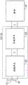
电信系统可以包括具有多个输入信道和多个输出信道的DAS 100(例如,MIMODAS)。基站101可以经由DAS 100中的头端单元102在通信上耦接到DAS 100。DAS 100包括在通信上耦接到头端单元102的远程单元103。远程单元可以包括接收天线端口104和发送天线端口105。在一些方面中,接收天线端口104可以表示多个接收天线,并且发送天线端口105可以表示多个发送天线。为了说明的目的,图1中绘出了一个头端单元和一个远程单元。但是,DAS 100中可以包括任何数量的头端单元和远程单元。A telecommunications system may include a DAS 100 (eg, MIMODAS) having multiple input channels and multiple output channels.
在一些方面中,头端单元102可以是可以与一个或多个基站或同DAS 100通信的其它收发器设备通信的主单元或其它合适的单元。头端单元102可以包括例如将光信号发送到远程单元103的光收发器。头端单元102或其它合适的单元可以与DAS 100的不同覆盖区域中的远程单元通信。In some aspects,
DAS 100可以经由头端单元102和服务于一个或多个覆盖区域的远程单元103向移动站或其它终端设备传送信号,以及传送来自移动站或其它终端设备的信号。头端单元102可以以任何合适的方式与基站101和远程单元103在通信上耦接。在DAS 100或其它电信系统中在通信上耦接设备可以涉及建立、维护或以其它方式使用通信链路(例如,电缆、光纤、无线链路等)以在设备之间传送信息。可以使用任何合适类型的通信链路。合适的通信链路可以是有线连接或无线连接。有线连接的类型可以包括例如经由铜缆、光纤或另一种合适的通信介质的连接。基站101和头端单元102之间的通信链路的类型可以与头端单元102和远程单元103之间的通信链路的类型相同或不同。DAS 100 may transmit signals to and from mobile stations or other terminal devices via
头端102单元可以将来自基站101的下行链路信号提供给远程单元103,并从远程单元103接收要提供给基站101的上行链路信号。下行链路信号可以包括从基站101提供并由远程单位103发送到覆盖区域的信号。上行链路信号可以包括由移动站或其它终端设备发送并由远程单元103接收的信号。下行链路信号和上行链路信号可以包括MIMO信号。The headend 102 unit may provide downlink signals from the
远程单元103可以在一个或多个覆盖区域中提供信号覆盖。在覆盖区域中提供信号覆盖可以包括将从头端单元102接收到的下行链路信号无线地发送到覆盖区域中的移动站或其它终端设备。在覆盖区域中提供信号覆盖也可以包括从覆盖区域中的移动通信设备或其它移动站或其它终端设备无线地接收上行链路信号。远程单元103可以将上行链路信号发送到头端单元102。头端单元102可以将上行链路信号发送到基站101。
虽然图1绘出了头端单元102和远程单元103之间的直接链路,但是其它实现方式也是可能的。在一些方面中,头端单元102可以经由一个或多个扩展单元或其它中间设备在通信上耦接到远程单元103。Although FIG. 1 depicts a direct link between
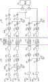
图2示出了根据一个方面的用于图1中的具有两个输入信道和两个输出信道(2x2)的DAS 100的示例常规体系架构的示意图。基站101包括经由头端单元102在通信上耦接到DAS 100的多个天线端口。头端单元102经由包含滤波部件的数字滤波和输送(“DFT”)单元200在通信上耦接到远程单元103。对于每个信道,该体系架构包括使用单独的A/D转换器和D/A转换器的专用信号路径。DAS 100包括具有两个上行链路路径201a、201b和两个下行链路路径202a、202b的四个信道。虽然示出了2x2MIMO DAS体系架构,但是在不脱离本公开的范围的情况下,该体系架构可以支持附加的信道(例如,4x4等)。2 shows a schematic diagram of an example conventional architecture for the DAS 100 of FIG. 1 with two input channels and two output channels (2x2), according to one aspect.
在上行链路方向上,上行链路路径201a、201b分别耦接到天线203a、203b。在远程单元103中,上行链路路径201a包括低噪声放大器204、混频器205、放大器206、抗混叠滤波器207、放大器208和A/D转换器209。远程单元在通信上耦接到DFT单元200,DFT单元200在上行链路路径201a中包括数字中频(“IF”)滤波器210。DFT单元200在通信上耦接到头端单元102,头端单元102包括D/A转换器211、模拟滤波器212、混频器213、放大器214和可变衰减器215。头端单元在通信上耦接到基站101。上行链路路径201b类似地包括在远程单元103中的低噪声放大器216、混频器217、放大器218、抗混叠滤波器219、放大器220和A/D转换器220,远程单元103在通信上耦接到DFT单元200中的数字IF滤波器222。在头端单元102中,上行链路路径201b包括D/A转换器223、模拟滤波器224、混频器225、放大器226和可变衰减器227。上行链路路径201a中的混频器205和上行链路路径201b中的混频器217耦接到振荡器228。上行链路路径201a中的混频器213和上行链路路径201b中的混频器225耦接到振荡器229。In the uplink direction,
在下行链路方向上,下行链路路径202a包括在头端单元102中的混频器230、抗混叠滤波器231和A/D转换器232,头端单元102耦接到DFT单元200中的数字IF滤波器233。下行链路路径202a包括在远处单元103中的D/A转换器234、模拟滤波器235、混频器236和功率放大器237。下行链路路径202b包括在头端单元102中的混频器238、抗混叠滤波器239和A/D转换器240,头端单元102耦接到DFT单元200中的数字IF滤波器241。下行链路路径202b包括在远程单元103中的D/A转换器242、模拟滤波器243、混频器244和功率放大器245。下行链路路径202a中的混频器230和下行链路路径202b中的混频器238耦接到振荡器246。下行链路路径202a中的混频器236以及混频器244耦接到振荡器247。下行链路路径202a、202b中的信号由远端单元103分别经由天线248a、248b发送。In the downlink direction, the
每个路径(上行链路路径201a、201b和下行链路路径202a、202b)包括单独的A/D转换器和D/A转换器,以用于转换每个路径中的信号,这是因为A/D转换器和D/A转换器不具有用于多于一个路径的足够带宽。Each path (
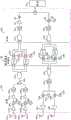
图3示出了根据一个方面的图2所示的常规体系架构的替代体系架构的示例的示意图,该替代体系架构的示例使用共享宽带A/D转换器。该体系架构包括两个上行链路路径300a、300b和两个下行链路路径301a、301b。上行链路路径300a、300b分别耦接到用于接收上行链路信号的天线302a、302b。上行链路路径300a、300b分别包括在远程单元310中的低噪声放大器303a、303b,分别耦接到振荡器305a、305b的混频器304a、304b,放大器306a、306b,抗混叠滤波器307a、307b,求和器308和共享宽带A/D转换器309。可以使用混频器304a、304b和振荡器305a、305b来混合上行链路路径300a、300b中的每个上行链路路径的上行链路信号,使得从混频器304a、304b输出的信号占据非重叠频带。混合信号使得它们占据非重叠频带可能导致信号之间的正交性,从而允许信号在由求和器308组合之后是可分离的。可以使用求和器308对信号求和并施加到共享宽带A/D转换器309以数字化输出信号。在DFT单元311中,经数字化的输出信号由可以限制输出信号的带宽的数字IF滤波器311a、311b单独滤波。可以使用混频器313a、313b将信号变换回适当的重叠中频,混频器313a、313b分别耦接到数字数控振荡器314a、314b。在头端单元316中,信号可以被施加到D/A转换器316a、316b。上行链路路径300a、300b分别包括模拟滤波器317a、317b,耦接到振荡器319的混频器318a、318b,放大器320a、320b以及可变衰减器321a、321b,以将信号变换成用于发送到基站322的适当的RF。3 shows a schematic diagram of an example of an alternative architecture to the conventional architecture shown in FIG. 2 using a shared wideband A/D converter, according to one aspect. The architecture includes two
下行链路路径301a、301b中的下行链路信号在它们经由头端单元315和DFT单元311从基站322发送到远程单元310可以经历相似的处理。在头端单元315中,下行链路信号是行进通过分别耦接到振荡器324a、324b的混频器323a、323b,抗混叠滤波器325a、325b,求和器326和共享宽带A/D转换器327。类似于远程单元310中的上行链路信号,头端单元315中的下行链路信号可以使用混频器323a、323b和振荡器324a、324b来混合,使得输出的下行链路信号占据非重叠频带。下行链路信号可以由共享宽带A/D转换器327进行滤波和数字化。经数字化的下行链路信号可以由数字IF滤波器328a、328b分离和滤波,数字IF滤波器328a、328b可以限制经数字化的下行链路信号的带宽。可以由混频器329a、329b将下行链路信号变换回适当的重叠中频,混频器329a、329b分别耦接到DFT单元311中的数字数控振荡器330a、330b。在远程单元310中,下行链路路径301a、301b包括单独的D/A转换器331a、331b,模拟滤波器332a、332b,耦接到振荡器334的混频器333a、333b以及功率放大器335a、335b。下行链路路径301a、301b中的下行链路信号由远程单元310分别经由天线336a、336b发送。The downlink signals in the
图4示出了根据一个方面的图2所示的常规体系架构的替代体系架构的另一个示例的示意图,该替代体系架构的另一个示例使用共享宽带A/D转换器和共享宽带D/A转换器。在上行链路路径400a、400b或下行链路路径401a、401b中的信号可以如图3中那样被变换到非重叠频带并被数字化。但是,不是像图3中那样将它们数字地变换回重叠的中频,而是可以将非重叠信号施加到共享宽带D/A转换器。从共享宽带D/A转换器输出的非重叠信号可以被变换回公共RF频率,并被施加到基站402处的单独端口(对于上行链路路径400a、400b中的上行链路信号)或远程单元404处的天线403a、403b(分别对于下行链路路径401a、401b中的下行链路信号)。4 shows a schematic diagram of another example of an alternative architecture to the conventional architecture shown in FIG. 2 using a shared wideband A/D converter and a shared wideband D/A, according to one aspect converter. The signals in the
在上行链路方向上,上行链路路径400a、400b分别耦接到天线432a、432b。在上行链路方向上,上行链路路径400a、400b分别包括在远程单元404中的低噪声放大器405a、405b,分别耦接到振荡器407a、407b的混频器406a、406b,放大器408a、408b,抗混叠滤波器409a、409b,求和器410和共享宽带A/D转换器411。远程单元404耦接到包括数字IF滤波器413a、413b的DFT单元412。DFT单元412耦接到头端单元414,头端单元414包括共享宽带D/A转换器415,模拟滤波器416,分别耦接到振荡器418a、418b的混频器417a、417b,放大器419a、419b以及可变衰减器420a、420b。In the uplink direction,
在下行链路方向上,头端单元414包括分别耦接到振荡器422a、422b的混频器421a、421b,抗混叠滤波器423a、423b,求和器424和共享宽带A/D转换器425。头端单元414耦接到包括数字IF滤波器426a、426b的DFT单元412。DFT单元412耦接到远程单元404。下行链路路径401a、401b包括共享宽带D/A转换器427,模拟滤波器428和分别耦接到振荡器430a、430b的混频器429a、429b,以及放大器431a、431b。In the downlink direction,
在一些方面中,MIMO DAS可以耦接到单输入单输出(“SISO”)基站。图5示出了用于被耦接到SISO基站并使用宽带A/D转换器和D/A转换器的MIMO DAS的示例体系架构的示意图。该体系架构包括经由DFT单元502和头端单元503耦接到SISO基站501的远程单元500。在上行链路方向上,上行链路路径504a、504b中的上行链路信号可以如图3中那样分别从天线505a、505b接收、变换到非重叠频率、并被数字化。在远程单元500中,上行链路路径504a、504b分别包括低噪声放大器506a、506b,分别耦接到振荡器508a、508b的混频器507a、507b,放大器509a、509b,抗混叠滤波器510a、510b,求和器511和共享宽带A/D转换器512。远程单元500中的上行链路信号可以使用混频器507a、507b和振荡器508a、508b变换到非重叠频带、由共享宽带A/D转换器512数字化并且被发送到DFT单元502。In some aspects, the MIMO DAS may be coupled to a single-input single-output ("SISO") base station. 5 shows a schematic diagram of an example architecture for a MIMO DAS coupled to a SISO base station and using wideband A/D converters and D/A converters. The architecture includes a
在DFT单元502中,非重叠上行链路信号可以分别施加到可变数字滤波器H1、H2,并且分别使用耦接到数字数控振荡器514a、514b的混频器513a、513b变换成重叠的RF或中频。可变数字滤波器H1、H2可以被调整以引导(steer)天线505a、505b的天线图案。在头端单元503中,上行链路信号可以使用共享宽带D/A转换器515转换成模拟信号、变换回RF、并且被发送到基站501处的信号端口。在头端单元503中,上行链路信号可以被施加到共享宽带D/A转换器515、模拟滤波器516、放大器517和可变衰减器518。In
类似地,在下行链路方向上,来自基站501的下行链路信号可以被数字化并被分开到下行链路路径519a、519b中。头端单元503可以包括耦接到振荡器521的混频器520、抗混叠滤波器522以及共享宽带A/D转换器523,用于将下行链路信号变换到非重叠频带并且数字化非重叠下行链路信号。下行链路信号可以被发送到DFT单元502,以便由可变数字滤波器H3、H4进行滤波。下行链路信号可以从DFT单元502发送到远程单元500。在远程单元500中,下行链路信号可以被施加到单独的D/A转换器524a、524b,使用模拟滤波器525a、525b、耦接到振荡器527的混频器526a,526b、以及功率放大器528a、528b单独地变换回RF,以用于由远程单元500经由天线529a、529b发送。类似于可变数字滤波器H1、H2,可变数字滤波器H3、H4可以被调整以引导天线529a、529b的天线图案。Similarly, in the downlink direction, the downlink signal from
图6示出了图5所示体系架构的示例替代的示意图,该示例替代在下行链路方向上使用共享宽带D/A转换器。头端单元503可以经由DFT单元601而耦接到远程单元600。在上行链路方向上,远程单元600和DFT 601包括与图5中的远程单元500和DFT 502相同的体系架构。具体而言,远程单元600分别包括耦接到天线603a、603b的上行链路路径602a、602b。远程单元600中的上行链路路径602a、602b包括低噪声放大器604a、604b,分别耦接到振荡器606a、606b的混频器605a、605b,放大器607a、607b,抗混叠滤波器608a、608b,求和器609和宽带A/D转换器610。DFT单元601包括可变数字滤波器H5、H6和分别耦接到数字数控振荡器612a、612b的混频器611a、611b。Figure 6 shows a schematic diagram of an example alternative to the architecture shown in Figure 5, the example alternative using a shared wideband D/A converter in the downlink direction.
在DFT 601中,来自头端单元503的下行链路数字信号可以由可变数字滤波器H7、H8单独地滤波,并且使用耦接到数控振荡器614a、614b的混频器613a、613b变换到非重叠频带。信号可以被发送到远程单元600。下行链路信号可以被施加到远程单元600中的共享宽带D/A转换器614和模拟滤波器615。来自模拟滤波器615的非重叠模拟输出可以使用分别耦接到振荡器617a、617b的模拟混频器616a、616b变换到适当的RF频率,由功率放大器618放大,并且由远程单元600经由天线619a、619b发送。In
虽然图5和图6示出了SISO基站的单个信号端口,但是本公开可以用MIMO基站的多个端口来实现。取决于DAS的安装,有可能获得可用MIMO基站实现方式以及DAS远程单元的天线波束引导实现的吞吐量增益。Although Figures 5 and 6 show a single signal port of a SISO base station, the present disclosure may be implemented with multiple ports of a MIMO base station. Depending on the DAS installation, it is possible to obtain throughput gains that can be achieved with MIMO base station implementations and antenna beam steering of the DAS remote units.
示例实施例Example embodiment
示例1包括多输入和多输出电信系统,该系统包括:多个信号路径;位于该多个信号路径中的混频器,这些混频器耦接到振荡器,以用于产生占据非重叠频带并表示无线信号的多个信号;耦接到该多个信号路径的求和器,用于对该多个信号求和以形成求和信号;以及用于将求和信号转换成数字信号的共享模数转换器。Example 1 includes a multiple-input and multiple-output telecommunications system comprising: a plurality of signal paths; mixers in the plurality of signal paths, the mixers being coupled to oscillators for generating frequencies occupying non-overlapping frequency bands and represents a plurality of signals of a wireless signal; a summer coupled to the plurality of signal paths for summing the plurality of signals to form a summation signal; and a share for converting the summation signal into a digital signal analog-to-digital converter.
示例2包括示例1的多输入和多输出电信系统,其中共享模数转换器在多个信号路径间共享,以用于将多个信号转换成多个数字信号。Example 2 includes the multiple-input and multiple-output telecommunications system of example 1, wherein the shared analog-to-digital converter is shared among the multiple signal paths for converting the multiple signals to the multiple digital signals.
示例3包括示例1-2中任何一项的多输入和多输出电信系统,其中振荡器包括用于产生彼此正交的多个信号的可变频率。Example 3 includes the multiple-input and multiple-output telecommunications system of any of Examples 1-2, wherein the oscillator includes a variable frequency for generating a plurality of signals that are orthogonal to each other.
示例4包括示例1-3中任何一项的多输入和多输出电信系统,该系统还包括:用于将数字信号转换成模拟信号的共享数模转换器。Example 4 includes the multiple-input and multiple-output telecommunications system of any of Examples 1-3, the system further comprising: a shared digital-to-analog converter for converting the digital signal to an analog signal.
示例5包括示例1-4中任何一项的多输入和多输出电信系统,该系统还包括:耦接到共享模数转换器用于限制数字信号的带宽的数字中频滤波器。Example 5 includes the multiple-input and multiple-output telecommunications system of any of Examples 1-4, further comprising: a digital intermediate frequency filter coupled to the shared analog-to-digital converter for limiting the bandwidth of the digital signal.
示例6包括示例1-5中任何一项的多输入和多输出电信系统,该系统还包括耦接到共享模数转换器的用于引导远程单元天线图案的可变数字滤波器。Example 6 includes the multiple-input and multiple-output telecommunications system of any of Examples 1-5, the system further comprising a variable digital filter coupled to the shared analog-to-digital converter for directing the remote unit antenna pattern.
示例7包括示例1-6中任何一项的多输入和多输出电信系统,其中该系统是分布式天线系统。Example 7 includes the multiple-input and multiple-output telecommunications system of any of Examples 1-6, wherein the system is a distributed antenna system.
示例8包括示例7的多输入和多输出电信系统,其中混频器、振荡器、求和器和共享模数转换器位于分布式天线系统的上行链路信号路径中。Example 8 includes the multiple-input and multiple-output telecommunications system of example 7, wherein the mixer, oscillator, summer, and shared analog-to-digital converter are located in the uplink signal path of the distributed antenna system.
示例9包括示例7-8中任何一项的多输入和多输出电信系统,其中混频器、振荡器、求和器和共享模数转换器位于分布式天线系统的下行链路信号路径中。Example 9 includes the multiple-input and multiple-output telecommunications system of any of Examples 7-8, wherein the mixer, oscillator, summer, and shared analog-to-digital converter are located in the downlink signal path of the distributed antenna system.
示例10包括在多输入和多输出电信系统中执行的方法,该方法包括:使用耦接到振荡器的混频器对在多个信号路径中接收到的信号进行频移,以产生占据非重叠频带并表示无线信号的多个信号;使用求和器对该多个信号进行求和以形成求和信号;以及使用宽带模数转换器将求和信号转换成数字信号。Example 10 includes a method performed in a multiple-input and multiple-output telecommunications system, the method comprising frequency shifting a signal received in a plurality of signal paths using a mixer coupled to an oscillator to produce occupancy non-overlapping frequency bands and multiple signals representing a wireless signal; summing the multiple signals using a summer to form a summed signal; and converting the summed signal to a digital signal using a wideband analog-to-digital converter.
示例11包括示例10的方法,其中宽带模数转换器在多个信号路径间共享,该方法还包括将该多个信号转换成多个数字信号。Example 11 includes the method of example 10, wherein the wideband analog-to-digital converter is shared among the plurality of signal paths, the method further comprising converting the plurality of signals to the plurality of digital signals.
示例12包括示例10-11中任何一项的方法,其中振荡器包括用于产生彼此正交的所述多个信号的可变频率。Example 12 includes the method of any of Examples 10-11, wherein the oscillator includes a variable frequency for generating the plurality of signals that are orthogonal to each other.
示例13包括示例10-12中任何一项的方法,该方法还包括使用宽带数模转换器将数字信号转换成模拟信号。Example 13 includes the method of any of Examples 10-12, further comprising converting the digital signal to an analog signal using a wideband digital-to-analog converter.
示例14包括示例10-13中任何一项的方法,该方法还包括使用耦接到宽带模数转换器的数字中频滤波器限制数字信号的带宽。Example 14 includes the method of any of Examples 10-13, further comprising limiting the bandwidth of the digital signal using a digital intermediate frequency filter coupled to the wideband analog-to-digital converter.
示例15包括示例10-14中任何一项的方法,该方法还包括使用耦接到宽带模数转换器的可变数字滤波器来引导远程单元天线图案。Example 15 includes the method of any of Examples 10-14, further comprising directing the remote unit antenna pattern using a variable digital filter coupled to the wideband analog-to-digital converter.
示例16包括示例10-15中任何一项的方法,其中该系统是分布式天线系统。Example 16 includes the method of any of Examples 10-15, wherein the system is a distributed antenna system.
示例17包括示例16的方法,其中混频器、振荡器、求和器和宽带模数转换器位于分布式天线系统的上行链路信号路径中。Example 17 includes the method of example 16, wherein the mixer, the oscillator, the summer, and the wideband analog-to-digital converter are located in the uplink signal path of the distributed antenna system.
示例18包括示例16-17中任何一项的方法,其中混频器、振荡器、求和器和宽带模数转换器位于分布式天线系统的下行链路信号路径中。Example 18 includes the method of any of Examples 16-17, wherein the mixer, oscillator, summer, and wideband analog-to-digital converter are located in the downlink signal path of the distributed antenna system.
对示例(包括图示示例)的前述描述仅仅是为了说明和描述的目的而呈现,并不旨在穷举或将主题限制为所公开的精确形式。在不脱离本公开的范围的情况下,其许多修改、适配和使用对本领域技术人员将是明显的。给出上述说明性示例是为了向读者介绍本文所讨论的一般主题,并不旨在限制所公开的概念的范围。The foregoing description of examples, including illustrated examples, has been presented for purposes of illustration and description only, and is not intended to be exhaustive or to limit the subject matter to the precise form disclosed. Numerous modifications, adaptations and uses thereof will be apparent to those skilled in the art without departing from the scope of this disclosure. The above illustrative examples are presented to introduce the reader to the general subject matter discussed herein, and are not intended to limit the scope of the disclosed concepts.
Claims (12)
Applications Claiming Priority (3)
| Application Number | Priority Date | Filing Date | Title |
|---|---|---|---|
| US201562155574P | 2015-05-01 | 2015-05-01 | |
| US62/155,574 | 2015-05-01 | ||
| PCT/US2016/030208WO2016179021A1 (en) | 2015-05-01 | 2016-04-29 | Multiple input multiple output distributed antenna system architectures |
Publications (2)
| Publication Number | Publication Date |
|---|---|
| CN107438956A CN107438956A (en) | 2017-12-05 |
| CN107438956Btrue CN107438956B (en) | 2020-11-03 |
Family
ID=57217774
Family Applications (1)
| Application Number | Title | Priority Date | Filing Date |
|---|---|---|---|
| CN201680021590.3AExpired - Fee RelatedCN107438956B (en) | 2015-05-01 | 2016-04-29 | Multiple-input multiple-output distributed antenna system architecture |
Country Status (4)
| Country | Link |
|---|---|
| US (2) | US10355754B2 (en) |
| EP (2) | EP3860066A1 (en) |
| CN (1) | CN107438956B (en) |
| WO (1) | WO2016179021A1 (en) |
Families Citing this family (10)
| Publication number | Priority date | Publication date | Assignee | Title |
|---|---|---|---|---|
| US6704545B1 (en)* | 2000-07-19 | 2004-03-09 | Adc Telecommunications, Inc. | Point-to-multipoint digital radio frequency transport |
| US8958789B2 (en) | 2002-12-03 | 2015-02-17 | Adc Telecommunications, Inc. | Distributed digital antenna system |
| KR20160081122A (en)* | 2014-12-30 | 2016-07-08 | 주식회사 쏠리드 | Distributed antenna system for multiple-input multiple-output signal |
| CN107438956B (en) | 2015-05-01 | 2020-11-03 | 安德鲁无线系统有限公司 | Multiple-input multiple-output distributed antenna system architecture |
| CN109660997B (en)* | 2018-11-26 | 2022-07-08 | 京信网络系统股份有限公司 | Configuration method and device of converter, computer equipment and storage medium |
| US10756786B1 (en)* | 2019-04-30 | 2020-08-25 | Corning Research & Development Corporation | Systems and methods for providing isolation for antennas in a wireless communication system |
| US12081247B2 (en)* | 2019-09-26 | 2024-09-03 | Altera Corporation | Systems and methods for electronically scanned array antennas |
| US12237858B2 (en)* | 2021-03-25 | 2025-02-25 | Skyworks Solutions, Inc. | Mobile devices with dual conversion of multiple frequency bands using a shared intermediate frequency |
| US12101108B2 (en)* | 2021-03-30 | 2024-09-24 | Skyworks Solutions, Inc. | Mobile devices with merged frequency range one and intermediate frequency signal path |
| US20240106466A1 (en)* | 2022-09-22 | 2024-03-28 | Qualcomm Incorporated | Transmitter hardware sharing |
Citations (2)
| Publication number | Priority date | Publication date | Assignee | Title |
|---|---|---|---|---|
| CN102668483A (en)* | 2009-12-21 | 2012-09-12 | 瑞典爱立信有限公司 | Iq-imbalance estimation for non-symmetrical pilot symbols |
| WO2014203249A1 (en)* | 2013-06-17 | 2014-12-24 | Elta Systems Ltd. | A system and method for receiving and processing array antenna signals |
Family Cites Families (27)
| Publication number | Priority date | Publication date | Assignee | Title |
|---|---|---|---|---|
| US5649287A (en)* | 1995-03-29 | 1997-07-15 | Telefonaktiebolaget Lm Ericsson | Orthogonalizing methods for antenna pattern nullfilling |
| US7548787B2 (en)* | 2005-08-03 | 2009-06-16 | Kamilo Feher | Medical diagnostic and communication system |
| AU2002309223A1 (en)* | 2002-05-30 | 2003-12-19 | Xtend Networks Ltd. | System and method to expand catv transmission spectrum using high frequency spectrum overlays |
| US7702049B2 (en)* | 2003-09-30 | 2010-04-20 | Intel Corporation | Signal conversion apparatus, systems, and methods |
| US7885178B2 (en)* | 2003-12-29 | 2011-02-08 | Intel Corporation | Quasi-parallel multichannel receivers for wideband orthogonal frequency division multiplexed communications and associated methods |
| US7590396B2 (en)* | 2005-10-06 | 2009-09-15 | Broadcom Corporation | Multimode communication device with shared signal path programmable filter |
| US8537745B2 (en)* | 2008-06-02 | 2013-09-17 | Qualcomm Incorporated | Multiplexing arrangements for multiple receive antennas |
| US8542616B2 (en)* | 2008-10-14 | 2013-09-24 | Texas Instruments Incorporated | Simultaneous multiple signal reception and transmission using frequency multiplexing and shared processing |
| CN102292949B (en) | 2009-01-13 | 2015-07-15 | Adc长途电讯有限公司 | Systems and methods for improved digital RF transmission in distributed antenna systems |
| US8412142B2 (en)* | 2009-04-09 | 2013-04-02 | Broadcom Corporation | Multiple frequency band information signal universal front end with adjustable ADC(s) |
| US8576768B2 (en)* | 2009-04-16 | 2013-11-05 | Qualcomm Incorporated | Hybrid multi-band receiver |
| US8346091B2 (en)* | 2009-04-29 | 2013-01-01 | Andrew Llc | Distributed antenna system for wireless network systems |
| US9144012B2 (en)* | 2010-09-23 | 2015-09-22 | Samsung Electronics Co., Ltd. | Method and system of MIMO and beamforming transmitter and receiver architecture |
| EP3843285A1 (en) | 2011-06-13 | 2021-06-30 | CommScope Technologies LLC | Distributed antenna system architectures |
| US8798103B2 (en) | 2011-11-03 | 2014-08-05 | Motorola Solutions, Inc. | Method and apparatus for a multi-antenna device that uses a single baseband filter and analog-to-digital converter |
| US9369171B2 (en)* | 2013-04-19 | 2016-06-14 | Key2mobile LLC | Multi-standard in building mobile radio access network |
| US9673842B2 (en) | 2012-04-25 | 2017-06-06 | Qualcomm Incorporated | Combining multiple desired signals into a single baseband signal |
| US9614629B2 (en)* | 2012-08-15 | 2017-04-04 | Commscope Technologies Llc | Telecommunication system using multiple Nyquist zone operations |
| US9955361B2 (en)* | 2013-02-26 | 2018-04-24 | Dali Systems Co., Ltd. | Method and system for WI-FI data transmission |
| BR112015021322A2 (en) | 2013-03-02 | 2017-07-18 | Cellular Specialties Inc | distributed antenna system having high near-far performance |
| US8874063B2 (en) | 2013-03-08 | 2014-10-28 | Qualcomm Incorporated | Simultaneous signal receiver with interspersed frequency allocation |
| KR101975830B1 (en)* | 2013-04-02 | 2019-05-09 | 한국전자통신연구원 | Beam forming device and method for forming beam thereof |
| US8884800B1 (en)* | 2013-07-31 | 2014-11-11 | Sony Corporation | Method and apparatus for performing analog-to-digital conversion on multiple input signals |
| WO2015122946A1 (en)* | 2014-02-13 | 2015-08-20 | Commscope Technologies Llc | Narrowband signal transport sub-system for distributed antenna system |
| US9705609B2 (en)* | 2014-04-15 | 2017-07-11 | Commscope Technologies Llc | Wideband remote unit for distributed antenna system |
| US9614662B2 (en)* | 2015-03-23 | 2017-04-04 | Broadcom Corporation | Multi-input wireless receiver based on RF sampling techniques |
| CN107438956B (en) | 2015-05-01 | 2020-11-03 | 安德鲁无线系统有限公司 | Multiple-input multiple-output distributed antenna system architecture |
- 2016
- 2016-04-29CNCN201680021590.3Apatent/CN107438956B/ennot_activeExpired - Fee Related
- 2016-04-29USUS15/571,239patent/US10355754B2/enactiveActive
- 2016-04-29EPEP20201572.3Apatent/EP3860066A1/ennot_activeWithdrawn
- 2016-04-29EPEP16789849.3Apatent/EP3289738B1/enactiveActive
- 2016-04-29WOPCT/US2016/030208patent/WO2016179021A1/ennot_activeCeased
- 2019
- 2019-07-15USUS16/511,253patent/US10715220B2/enactiveActive
Patent Citations (2)
| Publication number | Priority date | Publication date | Assignee | Title |
|---|---|---|---|---|
| CN102668483A (en)* | 2009-12-21 | 2012-09-12 | 瑞典爱立信有限公司 | Iq-imbalance estimation for non-symmetrical pilot symbols |
| WO2014203249A1 (en)* | 2013-06-17 | 2014-12-24 | Elta Systems Ltd. | A system and method for receiving and processing array antenna signals |
Also Published As
| Publication number | Publication date |
|---|---|
| CN107438956A (en) | 2017-12-05 |
| US10715220B2 (en) | 2020-07-14 |
| WO2016179021A1 (en) | 2016-11-10 |
| US10355754B2 (en) | 2019-07-16 |
| EP3289738A1 (en) | 2018-03-07 |
| EP3289738B1 (en) | 2020-12-02 |
| US20190341971A1 (en) | 2019-11-07 |
| US20180278299A1 (en) | 2018-09-27 |
| EP3289738A4 (en) | 2018-12-19 |
| EP3860066A1 (en) | 2021-08-04 |
Similar Documents
| Publication | Publication Date | Title |
|---|---|---|
| CN107438956B (en) | Multiple-input multiple-output distributed antenna system architecture | |
| KR101503324B1 (en) | Systems and methods for improved digital rf transport in distributed antenna systems | |
| US10090902B2 (en) | Distributed antenna system with uplink bandwidth for signal analysis | |
| CN1175609C (en) | Multi-carrier software defined radio transceiver and method for improving smart antenna performance | |
| US8509130B2 (en) | Techniques for flexible and efficient beamforming | |
| CN1735998A (en) | Frequency Selective Beamforming | |
| JP2019118117A (en) | Multiple-input multiple-output communication system | |
| CN112332892B (en) | Transceiver, receiving method and transmitting method | |
| CN1860645A (en) | Antenna system and method of configuring a radiation pattern | |
| US12224837B2 (en) | Systems and methods for reconfigurable repeaters for wireless telecommunications | |
| WO2016098101A1 (en) | Distributing digital communications signals in analog distributed antenna systems (dass) using programmable head-end units | |
| CN1454404A (en) | Fixed beam antenna array, base station and method for transmitting signals via a fixed beam antenna array | |
| CN102089933A (en) | Device for transmitting and preferably receiving signals, in particular mobile radio signals | |
| CN102763446A (en) | Method for receiving and transmitting signals, transmitter, receiver and system thereof | |
| US11804881B2 (en) | Radio base station and reception method at radio base station | |
| CN102804504B (en) | A transceiver module, antenna, base station and signal receiving method | |
| JP7087021B2 (en) | Signal processing methods and related devices | |
| CN1455972A (en) | Method for generating directional antenna beams and radio transmitter | |
| EP1784893A1 (en) | Transmitting and receiving radio frequency signals using an active electronically scanned array | |
| WO2019065158A1 (en) | Beam forming antenna | |
| CN111200451B (en) | Base station and its operation method and communication system | |
| EP3091668A1 (en) | Receiver arrangement for use in a digital repeater system | |
| WO2021052209A1 (en) | Radio remote apparatus, active antenna, and base station system | |
| WO2025119491A1 (en) | Analog beam squint suppression technique | |
| TW202234836A (en) | Multiband fdd (frequency division duplex) radio configuration for reduction in transmit and receive path resources |
Legal Events
| Date | Code | Title | Description |
|---|---|---|---|
| PB01 | Publication | ||
| PB01 | Publication | ||
| SE01 | Entry into force of request for substantive examination | ||
| SE01 | Entry into force of request for substantive examination | ||
| TA01 | Transfer of patent application right | ||
| TA01 | Transfer of patent application right | Effective date of registration:20200330 Address after:Buchdorf, Germany Applicant after:Andrew Wireless Systems GmbH Address before:North Carolina, USA Applicant before:CommScope Technologies LLC | |
| GR01 | Patent grant | ||
| GR01 | Patent grant | ||
| CF01 | Termination of patent right due to non-payment of annual fee | ||
| CF01 | Termination of patent right due to non-payment of annual fee | Granted publication date:20201103 |