CN107429683B - Positive displacement pump - Google Patents
Positive displacement pumpDownload PDFInfo
- Publication number
- CN107429683B CN107429683BCN201580077502.7ACN201580077502ACN107429683BCN 107429683 BCN107429683 BCN 107429683BCN 201580077502 ACN201580077502 ACN 201580077502ACN 107429683 BCN107429683 BCN 107429683B
- Authority
- CN
- China
- Prior art keywords
- valve
- valve body
- pump
- discharge
- valve seat
- Prior art date
- Legal status (The legal status is an assumption and is not a legal conclusion. Google has not performed a legal analysis and makes no representation as to the accuracy of the status listed.)
- Expired - Fee Related
Links
Images


Classifications
- F—MECHANICAL ENGINEERING; LIGHTING; HEATING; WEAPONS; BLASTING
- F04—POSITIVE - DISPLACEMENT MACHINES FOR LIQUIDS; PUMPS FOR LIQUIDS OR ELASTIC FLUIDS
- F04B—POSITIVE-DISPLACEMENT MACHINES FOR LIQUIDS; PUMPS
- F04B53/00—Component parts, details or accessories not provided for in, or of interest apart from, groups F04B1/00 - F04B23/00 or F04B39/00 - F04B47/00
- F04B53/10—Valves; Arrangement of valves
- F04B53/1037—Flap valves
- F04B53/1047—Flap valves the valve being formed by one or more flexible elements
- F04B53/106—Flap valves the valve being formed by one or more flexible elements the valve being a membrane
- F04B53/1065—Flap valves the valve being formed by one or more flexible elements the valve being a membrane fixed at its centre
- F—MECHANICAL ENGINEERING; LIGHTING; HEATING; WEAPONS; BLASTING
- F04—POSITIVE - DISPLACEMENT MACHINES FOR LIQUIDS; PUMPS FOR LIQUIDS OR ELASTIC FLUIDS
- F04B—POSITIVE-DISPLACEMENT MACHINES FOR LIQUIDS; PUMPS
- F04B43/00—Machines, pumps, or pumping installations having flexible working members
- F04B43/08—Machines, pumps, or pumping installations having flexible working members having tubular flexible members
- F04B43/10—Pumps having fluid drive
- F04B43/113—Pumps having fluid drive the actuating fluid being controlled by at least one valve
- F04B43/1136—Pumps having fluid drive the actuating fluid being controlled by at least one valve with two or more pumping chambers in parallel
- F—MECHANICAL ENGINEERING; LIGHTING; HEATING; WEAPONS; BLASTING
- F04—POSITIVE - DISPLACEMENT MACHINES FOR LIQUIDS; PUMPS FOR LIQUIDS OR ELASTIC FLUIDS
- F04B—POSITIVE-DISPLACEMENT MACHINES FOR LIQUIDS; PUMPS
- F04B45/00—Pumps or pumping installations having flexible working members and specially adapted for elastic fluids
- F04B45/02—Pumps or pumping installations having flexible working members and specially adapted for elastic fluids having bellows
- F—MECHANICAL ENGINEERING; LIGHTING; HEATING; WEAPONS; BLASTING
- F04—POSITIVE - DISPLACEMENT MACHINES FOR LIQUIDS; PUMPS FOR LIQUIDS OR ELASTIC FLUIDS
- F04B—POSITIVE-DISPLACEMENT MACHINES FOR LIQUIDS; PUMPS
- F04B53/00—Component parts, details or accessories not provided for in, or of interest apart from, groups F04B1/00 - F04B23/00 or F04B39/00 - F04B47/00
- F04B53/10—Valves; Arrangement of valves
- F—MECHANICAL ENGINEERING; LIGHTING; HEATING; WEAPONS; BLASTING
- F16—ENGINEERING ELEMENTS AND UNITS; GENERAL MEASURES FOR PRODUCING AND MAINTAINING EFFECTIVE FUNCTIONING OF MACHINES OR INSTALLATIONS; THERMAL INSULATION IN GENERAL
- F16K—VALVES; TAPS; COCKS; ACTUATING-FLOATS; DEVICES FOR VENTING OR AERATING
- F16K15/00—Check valves
- F16K15/14—Check valves with flexible valve members
- F16K15/148—Check valves with flexible valve members the closure elements being fixed in their centre
Landscapes
- Engineering & Computer Science (AREA)
- General Engineering & Computer Science (AREA)
- Mechanical Engineering (AREA)
- Reciprocating Pumps (AREA)
- Details Of Reciprocating Pumps (AREA)
- Check Valves (AREA)
Abstract
Description
Translated fromChinese技术领域technical field
本发明有关于容积泵,其为通过以蛇腹管、伸缩管等的可变形的构件来使泵室内的容积改变而将移送流体作移送的容积泵。The present invention relates to a volumetric pump that transfers a fluid to be transferred by changing the volume in a pump chamber with a deformable member such as a bellows or a telescopic tube.
背景技术Background technique
通过以蛇腹管、伸缩管等的可变形的构件来使泵室内的容积改变而将移送流体作移送的容积泵是众所周知的。在此种容积泵中,在泵的吸入口和泵室之间被设置有吸入阀,在泵的吐出口和泵室之间被设置有吐出阀。于此,例如,在下述专利文献1中揭示有一种容积泵,其具备具有圆筒状的阀座和沿着此圆筒状的阀座的内壁而滑动的阀体的吸入阀以及吐出阀。又,在下述专利文献2中揭示有一种容积泵,其具备具有圆筒状的阀座和沿着此圆筒状的阀座的内壁而滑动的球状的阀体的吸入阀以及吐出阀。A volumetric pump that transfers a transfer fluid by changing the volume in a pump chamber with a deformable member such as a bellows or an expansion tube is known. In this type of positive displacement pump, a suction valve is provided between the suction port of the pump and the pump chamber, and a discharge valve is provided between the discharge port of the pump and the pump chamber. Here, for example,
[先行技术文献][Prior Art Literature]
[专利文献][Patent Document]
专利文献1:日本特开2012-211512号公报Patent Document 1: Japanese Patent Laid-Open No. 2012-211512
专利文献2:日本特开2006-200429号公报Patent Document 2: Japanese Patent Laid-Open No. 2006-200429
发明内容Contents of the invention
发明要解决的问题The problem to be solved by the invention
在上述的专利文献1以及2中,均同样的,吸入阀以及吐出阀具有滑动部分,在此部分处所产生的粒子会有被混合于流体中的情形。In both of the
本发明有鉴于此课题而进行,目的为提供一种能够防止从滑动部分所产生的粒子混入至流体中的容积泵。The present invention has been made in view of this problem, and an object of the present invention is to provide a positive displacement pump capable of preventing particles generated from a sliding portion from being mixed into a fluid.
用于解决问题的方案solutions to problems
本发明的一种形态的容积泵为通过使蛇腹管伸缩来将移送流体作移送的容积泵。此容积泵具备:被可伸缩地配置并于内部形成泵室的、有底圆筒状的蛇腹管;和被设置于泵室的吸入侧并将移送流体引导至泵室中的吸入阀;和被设置于泵室的吐出侧并将移送流体从泵室吐出的吐出阀。又,吸入阀以及吐出阀分别具备阀座和阀体。阀体由可挠性的材质所成,并具备:与阀座间的位置关系为被作了固定的固定部;和在从固定部起而朝向阀座的方向以及移送流体所移动的方向之间的特定的方向上而延伸的阀部。A positive displacement pump according to one aspect of the present invention is a positive displacement pump that transfers a transfer fluid by expanding and contracting a bellows. This positive displacement pump is provided with: a bottomed cylindrical bellows that is telescopically arranged to form a pump chamber inside; and a suction valve that is provided on the suction side of the pump chamber and guides the transfer fluid into the pump chamber; and The discharge valve is installed on the discharge side of the pump chamber and discharges the transfer fluid from the pump chamber. Also, the suction valve and the discharge valve each include a valve seat and a valve body. The valve body is made of a flexible material, and has: a fixed part whose positional relationship with the valve seat is fixed; A valve portion extending in a specific direction between them.
亦即是,在此种容积泵中,吸入阀以及吐出阀的阀体由可挠性的材质所构成,并且,阀座与阀部的固定部分间的位置关系被作了固定,进而,阀部的可动部分在从阀体而朝向阀座延伸的方向以及流体所移动的方向之间的特定的方向上而延伸。故而,能够通过使阀座和阀体作推压接触来将流路堵塞,而能够防止阀座和阀体间的滑动。故而,通过在并未于泵室中具备滑动部分的蛇腹管泵等的容积泵中利用此种吸入阀以及吐出阀,能够防止从滑动部分所产生的粒子混入至流体中的情况。That is, in this positive displacement pump, the valve bodies of the suction valve and the discharge valve are made of flexible materials, and the positional relationship between the valve seat and the fixed part of the valve portion is fixed, and the valve The movable portion of the valve body extends in a specific direction between the direction extending from the valve body toward the valve seat and the direction in which the fluid moves. Therefore, the flow path can be blocked by bringing the valve seat and the valve body into contact with each other, thereby preventing slippage between the valve seat and the valve body. Therefore, by using such a suction valve and a discharge valve in a positive displacement pump such as a bellows pump that does not have a sliding portion in the pump chamber, it is possible to prevent particles generated from the sliding portion from being mixed into the fluid.
又,在本发明的其中一种形态的容积泵中,吸入阀的阀座被形成为朝向泵室而突出的圆筒状,阀部被形成为沿着移送流体所移动的方向而半径逐渐变大的大致圆锥状。In addition, in one aspect of the positive displacement pump of the present invention, the valve seat of the suction valve is formed in a cylindrical shape protruding toward the pump chamber, and the valve portion is formed so that the radius gradually changes along the direction in which the transfer fluid moves. Large roughly conical.
又,在本发明的其中一种形态的容积泵中,吐出阀的阀座被形成为朝向泵室而突出的圆筒状,阀部被形成为沿着移送流体所移动的方向而半径逐渐变大的大致圆锥状。Also, in the positive displacement pump according to one aspect of the present invention, the valve seat of the discharge valve is formed in a cylindrical shape protruding toward the pump chamber, and the valve portion is formed such that the radius gradually changes along the direction in which the transfer fluid moves. Large roughly conical.
当将吐出阀如此这般地来构成的情况时,例如,吐出阀亦可还具备将阀座和阀体间的位置关系作固定的阀体固定构件。又,阀体固定构件,亦可被形成为轴的位置为与阀座相互一致的大致圆柱状,并朝向泵室突出,且在突出于泵室中的端部的外周部分处,具备被与阀体作固定的部分。另外,于此之所谓“被与阀体作固定的部分”,例如,为公螺纹。When the discharge valve is configured in this way, for example, the discharge valve may further include a valve body fixing member that fixes the positional relationship between the valve seat and the valve body. In addition, the valve body fixing member may also be formed such that the position of the shaft is substantially cylindrical with the valve seat and protrudes toward the pump chamber, and at the outer peripheral portion of the end protruding from the pump chamber, a The valve body is used as a fixed part. In addition, the so-called "portion fixed to the valve body" here is, for example, a male thread.
又,于此情况,进而,吐出阀的阀体亦可还具备:被形成为轴的位置为与阀座相互一致的环状,并且于内周部分处具备被与阀体固定构件作固定的部分的环状部,阀部被与此环状体一体性地形成,并从环状部起而朝向前述特定的方向延伸。于此所谓“被与阀体固定构件作固定的部分”,例如,为母螺纹。于此情况,例如通过将阀体固定构件以相较于阀部而刚性为较高的材料来构成,能够防止起因于在流路中所产生的漩涡等而导致阀体固定构件的轴产生弯曲的情形,而能够降低阀体和阀座相互滑动的可能性。Also, in this case, furthermore, the valve body of the discharge valve may further include: the position of the shaft is formed in an annular shape that coincides with the valve seat, and a valve body fixed to the valve body fixing member is provided at the inner peripheral portion. Part of the annular portion, the valve portion is integrally formed with the annular body, and extends from the annular portion toward the aforementioned specific direction. Here, the "portion fixed to the valve body fixing member" is, for example, a female thread. In this case, for example, by configuring the valve body fixing member with a material that is more rigid than the valve portion, it is possible to prevent the shaft of the valve body fixing member from being bent due to eddies or the like generated in the flow path. The situation of the valve can reduce the possibility of the valve body and the valve seat sliding against each other.
又,当将吐出阀的阀座形成为朝向泵室而突出的圆筒状,并将阀部形成为沿着移送流体所移动的方向而半径逐渐变大的大致圆锥状的情况时,例如,吐出阀亦可还具备将阀座和阀体间的位置关系作固定的阀体固定构件。进而,阀体亦可具备朝向阀体固定构件而突出的突出部,并在突出部的外周部分处,具备被与阀体固定构件作固定的部分。Also, when the valve seat of the discharge valve is formed in a cylindrical shape protruding toward the pump chamber, and the valve portion is formed in a substantially conical shape with a gradually increasing radius along the direction in which the transferred fluid moves, for example, The discharge valve may further include a valve body fixing member that fixes the positional relationship between the valve seat and the valve body. Furthermore, the valve body may have a protruding portion protruding toward the valve body fixing member, and may have a portion fixed to the valve body fixing member at an outer peripheral portion of the protruding portion.
本发明的其中一种形态的容积泵,为通过以可变形的构件来使泵室内部的容积改变来将移送流体作移送的容积泵。此容积泵,具备:被设置于泵室的吸入侧并将移送流体引导至泵室中的吸入阀;和被设置于泵室的吐出侧并将前述移送流体从前述泵室吐出的吐出阀。吸入阀以及吐出阀,分别具备阀座和阀体。阀体由可挠性的材质所成,并具备:与阀座间的位置关系为被作了固定的固定部;和在从固定部起而朝向阀座的方向以及移送流体所移动的方向之间的特定的方向上而延伸的阀部。A displacement pump according to one aspect of the present invention is a displacement pump that transfers a transfer fluid by changing the volume inside the pump chamber with a deformable member. This positive displacement pump includes: a suction valve provided on the suction side of the pump chamber to guide the transfer fluid into the pump chamber; and a discharge valve provided on the discharge side of the pump chamber to discharge the transfer fluid from the pump chamber. The suction valve and the discharge valve each have a valve seat and a valve body. The valve body is made of a flexible material, and has: a fixed part whose positional relationship with the valve seat is fixed; A valve portion extending in a specific direction between them.
附图说明Description of drawings
图1为本发明的第1实施形态的容积泵的剖面图。Fig. 1 is a sectional view of a positive displacement pump according to a first embodiment of the present invention.
图2为对于该容积泵的吸入阀的构成例作展示的剖面图。Fig. 2 is a sectional view showing a configuration example of a suction valve of the positive displacement pump.
图3为对于该容积泵的吐出阀的构成例作展示的剖面图。Fig. 3 is a sectional view showing a configuration example of a discharge valve of the positive displacement pump.
图4为对于该容积泵的吐出阀的其他构成例作展示的剖面图。Fig. 4 is a sectional view showing another configuration example of the discharge valve of the positive displacement pump.
图5为对于其他构成例的容积泵的吸入阀的构成例作展示的剖面图。Fig. 5 is a cross-sectional view showing a configuration example of a suction valve of a positive displacement pump in another configuration example.
图6为对于该容积泵的吐出阀的构成例作展示的剖面图。Fig. 6 is a sectional view showing a configuration example of a discharge valve of the positive displacement pump.
具体实施方式Detailed ways
以下,针对本发明的实施形态的容积泵,一边参考图面一边作详细说明。Hereinafter, a positive displacement pump according to an embodiment of the present invention will be described in detail with reference to the drawings.
[第1实施形态][First Embodiment]
图1为本发明的一个实施形态的蛇腹管泵的剖面图及对于其周边机构作展示的图。另外,作为本实施形态的蛇腹管泵,虽列举出往返运动泵构造的所谓的双体型为例来作说明,但是,就算是身为所谓的单体型的蛇腹管泵,亦可作适用。Fig. 1 is a sectional view of a bellows pump according to an embodiment of the present invention and a view showing its peripheral mechanisms. In addition, as the bellows pump of the present embodiment, a so-called two-body type with a reciprocating pump structure is used as an example for explanation, but a so-called single-body type bellows pump is also applicable.
蛇腹管泵是如同下述一般而构成。在配置于中央部处的泵头1的两侧处,同轴配置有身为壳体构件的有底圆筒状的汽缸2a、2b,并在汽缸2a、2b的内部形成一对空间。在此些空间内,分别被同轴配置着有底圆筒状的蛇腹管3a、3b。The bellows pump is constructed as follows. Bottomed
蛇腹管3a、3b的开口端被固定在泵头1处,于泵头1的底部被固定有轴固定板4a、4b。蛇腹管3a、3b例如由氟树脂所成,并以将内侧作为泵室5a、5b且将外侧作为动作室6a、6b的方式来对汽缸2a、2b的内部空间作区隔。又,蛇腹管3a、3b具备沿着轴方向而被交互地形成的峰部12a以及谷部12b。Open ends of the
在轴固定板4a、4b处被固定有同轴地作延伸的轴7a、7b的其中一端。轴7a、7b的另外一端分别将汽缸2a、2b的底部中心隔着密封构件8而气密地作贯通,并一直延伸至汽缸2a、2b的外侧。在此轴7a、7b的另外一端处,通过螺帽10而被固定有连结板9a、9b。One end of the
连结板9a、9b在汽缸2a、2b的上下的位置处通过链接轴11a、11b而被作连结。各连结轴11a、11b通过螺杆15而被固定在连结板9a、9b处。The
在泵头1处,于面临泵的侧面的位置处被设置有移送流体的吸入口16和吐出口17。并且,在泵头1处,在从吸入口16起而至泵室5a、5b的位置处,被设置有吸入阀18a、18b,并在从泵室5a、5b起直到吐出口17的路径中,设置有吐出阀19a、19b。In the
另一方面,从未图示的空气压缩机等的动作流体源而来的动作流体、例如空气,通过调整器26而分别被限制为特定的压力并被供给至电磁阀27处。On the other hand, the operating fluid, such as air, from an operating fluid source such as an air compressor not shown is regulated to a specific pressure by the
假设动作室6a为排气状态,而动作室6b为空气导入状态,泵室5a进行膨胀工序,而泵室5b进行收缩工序。此时,由于吸入阀18a以及突出阀19b成为开状态,而吸入阀18b以及吐出阀19b成为闭状态,因此,应进行移送的液体从吸入口16而被导入至泵室5a中并从泵室5b经由吐出口17而被吐出。Assuming that the
接着,参考图2,针对吸入阀18b作更详细的说明。图2为吸入阀18b的剖面图。另外,在图2中,虽对于吸入阀18b作例示,但是,吸入阀18a亦被设为与吸入阀18b相同的构成。Next, referring to FIG. 2, the
如同图2中所示一般,吸入阀18b被螺合于泵头1处,并具备从泵头1而突出于泵室5b中的阀座21以及阀体22。阀座21,作为其中一例,被形成为圆筒状。又,在阀座21的其中一端的外周部分处,被形成有螺合部(公螺纹)211,并通过此螺合部211而被螺合于泵头1的母螺纹处。As shown in FIG. 2 , the
阀体22由氟树脂等的可挠性的材质所构成,作为其中一例,被形成为使轴的位置与阀座21相互一致的大致圆柱状。在阀体22的其中一端的外周部分处,被形成有螺合部(公螺纹)221,阀体22的其中一端通过此螺合部221而被螺合于泵头1的母螺纹处。又,阀体22的另外一端具备被形成为若是越远离泵头1的部分则半径会变得越大的大致圆锥状(号角形状)的阀部222。换言之,阀部222,具备沿着移送流体所移动的方向而半径逐渐变大的大致圆锥状的形状。亦即是,如同图2中所示一般,阀部222与被形成为圆柱状的阀体22的本体22A(固定部)相结合,其圆锥形状部被形成为以从本体22A起逐渐朝向阀座21的内壁而扩展的方式来延伸,并使其前端与内壁作推压接触。进而,在阀体22处,被形成有将泵头1的吸入口16和阀座21以及阀体22间的空间23作通连的吸入流路223。The
当泵室5b为进行膨胀工序的情况时,从吸入口16导入了的流体16,经由吸入流路223而被导入至空间23中,阀部222被流体推压。于此,阀体22由可挠性的材质所构成。又,阀部222与被形成为圆柱状的阀体22的本体相结合,并被形成为以从本体22A起逐渐朝向阀座21的内壁而扩展的方式来延伸且使其前端与内壁作推压接触。故而,若是阀部222被空间23内的流体所推压,则阀部222与流体一同地而被推压流动并变形,阀部222的前端部分224与阀座21的内壁部分相互分离。通过此,空间23与泵室5b相通连,流体被导入至泵室5b中。When the
另一方面,当泵室5b为进行收缩工序的情况时,通过泵室5b内的流体,阀部22被作推压。于此,阀体22由可挠性的材质所构成。又,阀部222与被形成为圆柱状的阀体22的本体相结合,并被形成为以从本体22A起逐渐朝向阀座21的内壁而扩展的方式来延伸且使其前端与内壁作推压接触。故而,若是阀部222被泵室5b内的流体所推压,则阀部222被朝向阀座21的内壁部分推压并扩展,阀部222的前端部分和阀座21的内壁部分相互接触。通过此,空间23与泵室5b被作区隔,而防止流体被从泵室5b导入至空间23中。On the other hand, when the
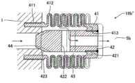
接着,参考图3,针对吐出阀19b作更详细的说明。图3为吐出阀19b的剖面图。另外,在图3中,虽是对于吐出阀19b作例示,但是,吐出阀19a亦被设为与吐出阀19b相同的构成。Next, the
如同图3中所示一般,吐出阀19b被螺合于泵头1处,并具备从泵头1而突出于泵室5b中的阀座31以及阀体固定构件32,还有与此阀体固定构件32作结合的阀体33。阀座31,作为其中一例,被形成为圆筒状。又,在阀座31的其中一端的外周部分处,被形成有螺合部(公螺纹)311,并通过此螺合部311而被螺合于泵头1的母螺纹处。As shown in FIG. 3, the
阀体固定构件32,作为其中一例,被形成为使轴的位置与阀座31相互一致的大致圆柱状。在阀体固定构件32的其中一端的外周部分处,被形成有螺合部(公螺纹)321,阀体固定构件32通过此螺合部321而被螺合于泵头1的母螺纹处。又,在阀体固定构件32的另外一端的外周部分处,被形成有螺合部(公螺纹)322,阀体固定构件32通过此螺合部322而被螺合于阀体33处。进而,在阀体固定构件32处,被形成有将泵头1的吸出口17和阀座31以及阀体固定构件32间的空间34作通连的吐出流路323。As one example, the valve
阀体33由氟树脂等的可挠性的材质所构成。又,阀体33,作为其中一例,具备被形成为使轴的位置与阀座31相互一致的环状并且于内周部分处被形成有与阀体固定构件32的螺合部322相螺合的螺合部(母螺纹)332(固定部)的环状部335。亦即是,阀体33通过此螺合部332而被螺合于阀体固定构件32处。又,阀体33构成被与此环状部335一体性地形成并且被形成为若是越接近泵头1则半径会变得越大的大致圆锥状(号角形状)的阀部331。换言之,阀部331具备沿着移送流体所移动的方向而半径逐渐变大的大致圆锥状的形状。亦即是,如同图3中所示一般,阀部331被形成为以从阀体固定构件322起逐渐朝向阀座31的内壁而扩展的方式来延伸,并使其前端与内壁作推压接触。The
当泵室5b为进行膨胀工序的情况时,泵室5b内成为减压状态,阀体33被朝向泵室5b内作拉张。于此,阀体33由可挠性的材质所构成。又,阀部331与被形成为圆柱状的阀体固定构件32相结合,并被形成为以从阀体固定构件322起逐渐朝向阀座31的内壁而扩展的方式来延伸且使其前端与内壁作推压接触。故而,若是阀体33被朝向泵室5b内拉张,则阀部331被朝向阀座31的内壁部分推压并扩展,阀部331的前端部分333和阀座31的内壁部分相互接触。通过此,空间34与泵室5b被作区隔,而防止流体被从空间34导入至泵室5b中。When the
另一方面,当泵室5b为进行收缩工序的情况时,通过泵室5b内的流体,阀部331被作推压。于此,阀体33由可挠性的材质所构成。又,阀部331与阀体固定构件32相结合,并被形成为以从阀体固定构件322起逐渐朝向阀座31的内壁而扩展的方式来延伸且使其前端与内壁作推压接触。故而,若是阀部331被泵室5b内的流体所推压,则阀部331的前端部分333与流体一同地而被推压流动,阀部331的前端部分333与阀座31的内壁部分相互分离。通过此,空间34与泵室5b相通连,流体从泵室5b而被排出至吐出口17处。On the other hand, when the
亦即是,在本实施形态的容积泵中,阀体由可挠性的材质所构成,并且阀座与阀部的固定部分间的位置关系被作了固定,进而,阀部的可动部分在从阀体而朝向阀座延伸的方向以及流体所移动的方向之间的特定的方向上而延伸。故而,能够通过使阀座和阀体作推压接触来将流路堵塞,而能够防止阀座和阀体间的滑动。故而,通过在并未于泵室中具备滑动部分的蛇腹管泵或伸缩管泵等的容积泵中利用本实施形态的吸入阀以及吐出阀,能够防止从滑动部分所产生的粒子混入至流体中的情况。That is, in the positive displacement pump of this embodiment, the valve body is made of a flexible material, and the positional relationship between the valve seat and the fixed portion of the valve portion is fixed, and furthermore, the movable portion of the valve portion It extends in a specific direction between the direction extending from the valve body toward the valve seat and the direction in which the fluid moves. Therefore, the flow path can be blocked by bringing the valve seat and the valve body into contact with each other, thereby preventing slippage between the valve seat and the valve body. Therefore, by using the suction valve and the discharge valve of the present embodiment in a positive displacement pump such as a bellows pump or a bellows pump that does not have a sliding portion in the pump chamber, it is possible to prevent particles generated from the sliding portion from being mixed into the fluid. Case.
又,在本实施形态的吐出阀19b中,如同图3中所示一般,阀体固定构件32被形成为圆柱状,在其端部的外周部分处,被形成有螺合部322。又,在本实施形态中,阀体33具备被形成为使轴的位置与阀座31相互一致的环状并且于内周部分处被形成有与阀体固定构件32的螺合部322相螺合的螺合部(母螺纹)332的环状部335。又,阀部331被与此环状部335一体性地形成,并从此环状部335起而朝向上述特定的方向延伸。故而,例如通过将阀体固定构件32以某种程度以上的刚性为高的材料来构成,能够防止起因于在流路中所产生的漩涡等而导致阀体固定构件32的轴产生弯曲的情形,而能够降低阀体33和阀座31相互滑动的可能性。于此,被使用在阀体固定部32处的材料的刚性至少较在阀体33处所使用的材料的刚性而更大。Moreover, in the
[其他构成例][Other configuration examples]
在图3所示的例中,将阀体固定构件32的螺合部322设为公螺纹,并将阀体33的螺合部332设为母螺纹。然而,例如,亦可如同在图4中所示一般,将阀体固定构件32'的螺合部322'设为公螺纹,并将阀体33'的螺合部332'(固定部)设为母螺纹。另外,在图4中所示的吐出阀19b',在其他构成上,被设为与图3中所示的吐出阀19b相同的构成。In the example shown in FIG. 3, the threaded
又,在防止阀座和阀体间的滑动的观点上,亦可考虑将吸入阀以及吐出阀分别如同在图5以及图6中所示一般地来构成。图5为其他的构成例的吸入阀18b"的剖面图。图6为其他的构成例的吐出阀19b"的剖面图。另外,在图5以及图6中所示的例,亦同样的,吸入阀以及吐出阀以外的构成被设为与参考图1所作了说明的构成相同的构成。In addition, from the viewpoint of preventing sliding between the valve seat and the valve body, it is conceivable to configure the suction valve and the discharge valve as shown in FIGS. 5 and 6 , respectively. Fig. 5 is a cross-sectional view of a
如同图5中所示一般,其他的构成例的吸入阀18b",具备将泵头1作为阀座而起作用的阀体42、和由可挠性的材料所成并将阀体42的一部分相对于泵头1而可移动地作保持的阀体保持构件41。阀体保持构件41被形成为大致圆筒状,于其中一端的外周部分处具备与泵头1之间的连结部(公螺纹)411,于另外一端的内周部分处具备与阀体42间的连结部(母螺纹)413,于此些的连结部之间的部分处具备蛇腹部412。As shown in FIG. 5, the
又,如同图5中所示一般,阀体42被形成为从阀体保持构件41的连结部413起朝向泵头1而延伸的大致圆柱状。又,阀体42于其中一端的外周部分处具备与阀体保持构件41间的连结部(公螺纹)421,并于另外一端处具备与泵头1间的抵接部分423。如图5中所示一般,阀体42的半径在与泵头1之间的抵接部分423处,朝向与流路逆行的方向而逐渐减少。又,在阀体42处,被形成有将阀体保持构件41和阀体42间的空间33与泵室5b作通连的流路422。Also, as shown in FIG. 5 , the
如同图6中所示一般,其他的构成例的吐出阀19b"被螺合于泵头1处,并具备从泵头1而突出于泵室5b中的阀座51、和通过泵头1以及阀座51而被作卡止并且在通过阀座51以及泵头1所区隔出的空间53中突出的阀体52。阀座51被形成为大致有底圆筒状。又,在阀座51的其中一端的外周部分处,被形成有螺合部(公螺纹)511,并通过此螺合部511而被螺合于泵头1的母螺纹处。进而,在阀体51的底部处被形成有将通过阀座51以及泵头1所区隔出的空间53和泵室5b作通连的流路512。进而,在阀座51处被设置有与阀体52之间的抵接部分513。此抵接部分513位于在流路512和阀座51的底部间的边界部分处。As shown in FIG. 6, the
如图6中所示一般,阀体52由可挠性的材质所构成,并被形成为使轴的位置与阀座51相互一致的大致有底圆筒状。又,阀体52于其中一端具备通过泵头1以及阀座51而被作卡止的被卡止部521,并在位置于另外一端的底部523处而具备与阀座51相抵接的抵接部525。又,阀体52在被卡止部521以及抵接部525之间的部分处,具备蛇腹部522。在阀体52的底部523处被形成有将阀体52内的空间54和通过阀座51以及泵头1所区隔出的空间53作通连的流路524。又,底部523的半径在与阀座51之间的抵接部525处,朝向与流路逆行的方向而逐渐减少。Generally, as shown in FIG. 6 , the valve body 52 is made of a flexible material, and is formed in a substantially bottomed cylindrical shape in which the position of the shaft coincides with that of the valve seat 51 . Also, the valve body 52 has a locked portion 521 at one end thereof that is locked by the
又,本发明只要是并未于泵室中具备滑动部分的容积泵,则亦可适用在蛇腹管泵以外的泵中。作为此种容积泵,例如可列举出伸缩管泵。In addition, the present invention can also be applied to pumps other than bellows pumps as long as they are positive displacement pumps that do not include a sliding portion in the pump chamber. As such a positive displacement pump, for example, a bellows pump is mentioned.
[符号说明][Symbol Description]
1:泵头;2a、2b:汽缸;3a、3b:蛇腹管;5a、5b:泵室;6a、6b:动作室;11a、11b:连接轴;16:吸入口;17:吐出口;18a、18b:吸入阀;19a、19b:吐出阀;21、31:阀座;22、33:阀体;222、331:阀部。1: pump head; 2a, 2b: cylinder; 3a, 3b: bellows; 5a, 5b: pump chamber; 6a, 6b: action chamber; 11a, 11b: connecting shaft; 16: suction port; 17: discharge port; 18a , 18b: suction valve; 19a, 19b: discharge valve; 21, 31: valve seat; 22, 33: valve body; 222, 331: valve part.
Claims (7)
Translated fromChineseApplications Claiming Priority (1)
| Application Number | Priority Date | Filing Date | Title |
|---|---|---|---|
| PCT/JP2015/056940WO2016143057A1 (en) | 2015-03-10 | 2015-03-10 | Positive displacement pump |
Publications (2)
| Publication Number | Publication Date |
|---|---|
| CN107429683A CN107429683A (en) | 2017-12-01 |
| CN107429683Btrue CN107429683B (en) | 2019-10-15 |
Family
ID=56878825
Family Applications (1)
| Application Number | Title | Priority Date | Filing Date |
|---|---|---|---|
| CN201580077502.7AExpired - Fee RelatedCN107429683B (en) | 2015-03-10 | 2015-03-10 | Positive displacement pump |
Country Status (6)
| Country | Link |
|---|---|
| US (1) | US10704547B2 (en) |
| JP (1) | JP6046856B1 (en) |
| KR (1) | KR102199145B1 (en) |
| CN (1) | CN107429683B (en) |
| TW (1) | TWI675148B (en) |
| WO (1) | WO2016143057A1 (en) |
Families Citing this family (5)
| Publication number | Priority date | Publication date | Assignee | Title |
|---|---|---|---|---|
| CN106640581B (en)* | 2016-12-26 | 2020-07-03 | 常州瑞择微电子科技有限公司 | Air sac pump with good sealing performance |
| JP6912004B2 (en)* | 2018-05-31 | 2021-07-28 | 株式会社村田製作所 | Fluid control device |
| CN115605667A (en) | 2020-04-02 | 2023-01-13 | 艺达思健康与科学有限责任公司(Us) | Precision displacement pump with bellows seal |
| CN112302915B (en)* | 2020-10-27 | 2021-08-31 | 浙江大学 | A bellows pump with built-in damper |
| CN112412731A (en)* | 2020-11-18 | 2021-02-26 | 崔海龙 | Air sac pump |
Citations (4)
| Publication number | Priority date | Publication date | Assignee | Title |
|---|---|---|---|---|
| CN2306334Y (en)* | 1997-06-02 | 1999-02-03 | 上海贺众饮水设备有限公司 | Water pump for drinking water machine |
| CN202327259U (en)* | 2011-11-17 | 2012-07-11 | 黄山市必利精密塑业科技有限公司 | Check valve |
| JP2014051950A (en)* | 2012-09-10 | 2014-03-20 | Nippon Pillar Packing Co Ltd | Bellows pump |
| CN104066986A (en)* | 2012-01-19 | 2014-09-24 | 韦纽斯有限公司 | A tube pump |
Family Cites Families (23)
| Publication number | Priority date | Publication date | Assignee | Title |
|---|---|---|---|---|
| US2859771A (en)* | 1954-06-28 | 1958-11-11 | Jersey Prod Res Co | Valve |
| US2833306A (en)* | 1955-06-10 | 1958-05-06 | Otis Eng Co | Check valve |
| JPS4533003Y1 (en) | 1965-04-07 | 1970-12-16 | ||
| US3473561A (en)* | 1966-03-29 | 1969-10-21 | Bert N Svenson | Check valve with supported closure member |
| JPS5249844B2 (en) | 1973-09-05 | 1977-12-20 | ||
| US4090818A (en) | 1976-05-25 | 1978-05-23 | Hope Henry F | Adjustable metering pump |
| US4609006A (en)* | 1984-11-29 | 1986-09-02 | American Standard Inc. | Diverter |
| JPH031667Y2 (en) | 1986-07-30 | 1991-01-18 | ||
| DE69107728D1 (en)* | 1990-08-15 | 1995-04-06 | Horstine Farmery Ltd | Agricultural Chemical Dispenser. |
| US5975360A (en)* | 1991-05-20 | 1999-11-02 | Ophardt; Heiner | Capped piston pump |
| FR2679620B1 (en)* | 1991-07-25 | 1993-10-29 | Oreal | ADJUSTABLE VALVE. |
| US5893707A (en)* | 1994-03-03 | 1999-04-13 | Simmons; John M. | Pneumatically shifted reciprocating pump |
| JPH11201045A (en) | 1998-01-07 | 1999-07-27 | Copal Co Ltd | Bellows pump |
| JP3574641B2 (en)* | 2002-04-19 | 2004-10-06 | 株式会社イワキ | Pump system |
| JP3989334B2 (en)* | 2002-08-23 | 2007-10-10 | 株式会社イワキ | Double reciprocating bellows pump |
| JP2006200429A (en) | 2005-01-20 | 2006-08-03 | Iwaki Co Ltd | Bellows pump |
| US8579605B2 (en) | 2006-03-17 | 2013-11-12 | Jackey Chiou | DC-AC frequency converter type mucus suction device |
| WO2009113804A2 (en) | 2008-03-12 | 2009-09-17 | 피에스피 주식회사 | Fluid pump |
| JP2009250363A (en)* | 2008-04-08 | 2009-10-29 | Alps Electric Co Ltd | Check valve |
| JP5720888B2 (en) | 2011-03-30 | 2015-05-20 | 株式会社イワキ | Bellows pump |
| WO2013135883A1 (en) | 2012-03-16 | 2013-09-19 | Meadwestvaco Calmar Netherlands B.V. | Venting pump device |
| CA2772507C (en)* | 2012-03-20 | 2018-12-18 | Gotohti.Com Inc. | Adaptive preload pump |
| JP5912849B2 (en) | 2012-05-21 | 2016-04-27 | 日本ピラー工業株式会社 | Horizontal bellows pump |
- 2015
- 2015-03-10USUS15/553,553patent/US10704547B2/ennot_activeExpired - Fee Related
- 2015-03-10WOPCT/JP2015/056940patent/WO2016143057A1/ennot_activeCeased
- 2015-03-10KRKR1020177023802Apatent/KR102199145B1/ennot_activeExpired - Fee Related
- 2015-03-10JPJP2016501469Apatent/JP6046856B1/ennot_activeExpired - Fee Related
- 2015-03-10CNCN201580077502.7Apatent/CN107429683B/ennot_activeExpired - Fee Related
- 2015-03-23TWTW104109184Apatent/TWI675148B/ennot_activeIP Right Cessation
Patent Citations (4)
| Publication number | Priority date | Publication date | Assignee | Title |
|---|---|---|---|---|
| CN2306334Y (en)* | 1997-06-02 | 1999-02-03 | 上海贺众饮水设备有限公司 | Water pump for drinking water machine |
| CN202327259U (en)* | 2011-11-17 | 2012-07-11 | 黄山市必利精密塑业科技有限公司 | Check valve |
| CN104066986A (en)* | 2012-01-19 | 2014-09-24 | 韦纽斯有限公司 | A tube pump |
| JP2014051950A (en)* | 2012-09-10 | 2014-03-20 | Nippon Pillar Packing Co Ltd | Bellows pump |
Also Published As
| Publication number | Publication date |
|---|---|
| KR102199145B1 (en) | 2021-01-06 |
| JPWO2016143057A1 (en) | 2017-04-27 |
| JP6046856B1 (en) | 2016-12-21 |
| US20180051692A1 (en) | 2018-02-22 |
| TW201632732A (en) | 2016-09-16 |
| KR20170127426A (en) | 2017-11-21 |
| US10704547B2 (en) | 2020-07-07 |
| TWI675148B (en) | 2019-10-21 |
| CN107429683A (en) | 2017-12-01 |
| WO2016143057A1 (en) | 2016-09-15 |
Similar Documents
| Publication | Publication Date | Title |
|---|---|---|
| CN107429683B (en) | Positive displacement pump | |
| CN103477074B (en) | bellows pump | |
| US7806668B2 (en) | Flexible tube for supplying chemical liquid | |
| EP2706235A1 (en) | Bellows pump | |
| JP2010077976A (en) | Bellows pump and method of operating the same | |
| US7758321B2 (en) | Pump apparatus | |
| TWI630337B (en) | Fluid control valve | |
| WO2016006043A1 (en) | Coil-spring fixing structure and duplex reciprocating pump | |
| WO2008076817A1 (en) | Pipette seal | |
| CN105745446A (en) | fluid equipment | |
| JP6228830B2 (en) | Valve and bellows pump using the valve | |
| JP6423496B1 (en) | Diaphragm pump | |
| WO2020238825A1 (en) | Scroll compressor | |
| JP7455332B2 (en) | diaphragm pump | |
| CN119907889A (en) | Bellows pump | |
| JP2004251198A (en) | Bellows and bellows pump | |
| CN120273990A (en) | Linkage shaft structure and reciprocating pump with same | |
| JP2017150401A (en) | Bellows pump | |
| JP2023007123A (en) | diaphragm pump | |
| WO2018135156A1 (en) | Bellows pump | |
| CN114439801A (en) | Valve core assembly with cavitation-resistant function |
Legal Events
| Date | Code | Title | Description |
|---|---|---|---|
| PB01 | Publication | ||
| PB01 | Publication | ||
| SE01 | Entry into force of request for substantive examination | ||
| SE01 | Entry into force of request for substantive examination | ||
| GR01 | Patent grant | ||
| GR01 | Patent grant | ||
| CF01 | Termination of patent right due to non-payment of annual fee | Granted publication date:20191015 | |
| CF01 | Termination of patent right due to non-payment of annual fee |