CN107405055B - One-piece bending neck for articulating ultrasound probe - Google Patents
One-piece bending neck for articulating ultrasound probeDownload PDFInfo
- Publication number
- CN107405055B CN107405055BCN201680013261.4ACN201680013261ACN107405055BCN 107405055 BCN107405055 BCN 107405055BCN 201680013261 ACN201680013261 ACN 201680013261ACN 107405055 BCN107405055 BCN 107405055B
- Authority
- CN
- China
- Prior art keywords
- tube
- neck
- pair
- segment
- links
- Prior art date
- Legal status (The legal status is an assumption and is not a legal conclusion. Google has not performed a legal analysis and makes no representation as to the accuracy of the status listed.)
- Active
Links
- 239000000523sampleSubstances0.000titleclaimsdescription25
- 238000002604ultrasonographyMethods0.000titleclaimsdescription9
- 238000005452bendingMethods0.000titleabstractdescription8
- 238000003754machiningMethods0.000claimsabstractdescription5
- 238000000034methodMethods0.000claimsdescription13
- 238000004873anchoringMethods0.000claims2
- 210000003739neckAnatomy0.000description61
- 238000013175transesophageal echocardiographyMethods0.000description3
- 238000003384imaging methodMethods0.000description2
- 239000000463materialSubstances0.000description2
- 238000013459approachMethods0.000description1
- 230000000295complement effectEffects0.000description1
- 238000003780insertionMethods0.000description1
- 230000037431insertionEffects0.000description1
- 238000003698laser cuttingMethods0.000description1
- 238000004519manufacturing processMethods0.000description1
- 239000002184metalSubstances0.000description1
- 229910001220stainless steelInorganic materials0.000description1
- 239000010935stainless steelSubstances0.000description1
- 238000012285ultrasound imagingMethods0.000description1
Images


Classifications
- A—HUMAN NECESSITIES
- A61—MEDICAL OR VETERINARY SCIENCE; HYGIENE
- A61B—DIAGNOSIS; SURGERY; IDENTIFICATION
- A61B1/00—Instruments for performing medical examinations of the interior of cavities or tubes of the body by visual or photographical inspection, e.g. endoscopes; Illuminating arrangements therefor
- A61B1/005—Flexible endoscopes
- A61B1/008—Articulations
- A—HUMAN NECESSITIES
- A61—MEDICAL OR VETERINARY SCIENCE; HYGIENE
- A61B—DIAGNOSIS; SURGERY; IDENTIFICATION
- A61B1/00—Instruments for performing medical examinations of the interior of cavities or tubes of the body by visual or photographical inspection, e.g. endoscopes; Illuminating arrangements therefor
- A61B1/00064—Constructional details of the endoscope body
- A61B1/0011—Manufacturing of endoscope parts
- A—HUMAN NECESSITIES
- A61—MEDICAL OR VETERINARY SCIENCE; HYGIENE
- A61B—DIAGNOSIS; SURGERY; IDENTIFICATION
- A61B1/00—Instruments for performing medical examinations of the interior of cavities or tubes of the body by visual or photographical inspection, e.g. endoscopes; Illuminating arrangements therefor
- A61B1/005—Flexible endoscopes
- A61B1/0051—Flexible endoscopes with controlled bending of insertion part
- A61B1/0055—Constructional details of insertion parts, e.g. vertebral elements
- A—HUMAN NECESSITIES
- A61—MEDICAL OR VETERINARY SCIENCE; HYGIENE
- A61B—DIAGNOSIS; SURGERY; IDENTIFICATION
- A61B1/00—Instruments for performing medical examinations of the interior of cavities or tubes of the body by visual or photographical inspection, e.g. endoscopes; Illuminating arrangements therefor
- A61B1/005—Flexible endoscopes
- A61B1/0051—Flexible endoscopes with controlled bending of insertion part
- A61B1/0057—Constructional details of force transmission elements, e.g. control wires
- A—HUMAN NECESSITIES
- A61—MEDICAL OR VETERINARY SCIENCE; HYGIENE
- A61B—DIAGNOSIS; SURGERY; IDENTIFICATION
- A61B8/00—Diagnosis using ultrasonic, sonic or infrasonic waves
- A61B8/12—Diagnosis using ultrasonic, sonic or infrasonic waves in body cavities or body tracts, e.g. by using catheters
- A—HUMAN NECESSITIES
- A61—MEDICAL OR VETERINARY SCIENCE; HYGIENE
- A61B—DIAGNOSIS; SURGERY; IDENTIFICATION
- A61B8/00—Diagnosis using ultrasonic, sonic or infrasonic waves
- A61B8/44—Constructional features of the ultrasonic, sonic or infrasonic diagnostic device
- A61B8/4444—Constructional features of the ultrasonic, sonic or infrasonic diagnostic device related to the probe
- A61B8/445—Details of catheter construction
- A—HUMAN NECESSITIES
- A61—MEDICAL OR VETERINARY SCIENCE; HYGIENE
- A61M—DEVICES FOR INTRODUCING MEDIA INTO, OR ONTO, THE BODY; DEVICES FOR TRANSDUCING BODY MEDIA OR FOR TAKING MEDIA FROM THE BODY; DEVICES FOR PRODUCING OR ENDING SLEEP OR STUPOR
- A61M25/00—Catheters; Hollow probes
- A61M25/01—Introducing, guiding, advancing, emplacing or holding catheters
- A61M25/0105—Steering means as part of the catheter or advancing means; Markers for positioning
- A61M25/0133—Tip steering devices
- A61M25/0138—Tip steering devices having flexible regions as a result of weakened outer material, e.g. slots, slits, cuts, joints or coils
- A—HUMAN NECESSITIES
- A61—MEDICAL OR VETERINARY SCIENCE; HYGIENE
- A61M—DEVICES FOR INTRODUCING MEDIA INTO, OR ONTO, THE BODY; DEVICES FOR TRANSDUCING BODY MEDIA OR FOR TAKING MEDIA FROM THE BODY; DEVICES FOR PRODUCING OR ENDING SLEEP OR STUPOR
- A61M25/00—Catheters; Hollow probes
- A61M25/01—Introducing, guiding, advancing, emplacing or holding catheters
- A61M25/0105—Steering means as part of the catheter or advancing means; Markers for positioning
- A61M25/0133—Tip steering devices
- A61M25/0147—Tip steering devices with movable mechanical means, e.g. pull wires
- A—HUMAN NECESSITIES
- A61—MEDICAL OR VETERINARY SCIENCE; HYGIENE
- A61B—DIAGNOSIS; SURGERY; IDENTIFICATION
- A61B1/00—Instruments for performing medical examinations of the interior of cavities or tubes of the body by visual or photographical inspection, e.g. endoscopes; Illuminating arrangements therefor
- A61B1/00064—Constructional details of the endoscope body
- A61B1/00071—Insertion part of the endoscope body
- A61B1/00078—Insertion part of the endoscope body with stiffening means
- A—HUMAN NECESSITIES
- A61—MEDICAL OR VETERINARY SCIENCE; HYGIENE
- A61B—DIAGNOSIS; SURGERY; IDENTIFICATION
- A61B17/00—Surgical instruments, devices or methods
- A61B17/00234—Surgical instruments, devices or methods for minimally invasive surgery
- A61B2017/00292—Surgical instruments, devices or methods for minimally invasive surgery mounted on or guided by flexible, e.g. catheter-like, means
- A61B2017/003—Steerable
- A61B2017/00305—Constructional details of the flexible means
- A61B2017/00314—Separate linked members
- A—HUMAN NECESSITIES
- A61—MEDICAL OR VETERINARY SCIENCE; HYGIENE
- A61B—DIAGNOSIS; SURGERY; IDENTIFICATION
- A61B17/00—Surgical instruments, devices or methods
- A61B17/00234—Surgical instruments, devices or methods for minimally invasive surgery
- A61B2017/00292—Surgical instruments, devices or methods for minimally invasive surgery mounted on or guided by flexible, e.g. catheter-like, means
- A61B2017/003—Steerable
- A61B2017/00318—Steering mechanisms
- A61B2017/00323—Cables or rods
- A61B2017/00327—Cables or rods with actuating members moving in opposite directions
- A—HUMAN NECESSITIES
- A61—MEDICAL OR VETERINARY SCIENCE; HYGIENE
- A61M—DEVICES FOR INTRODUCING MEDIA INTO, OR ONTO, THE BODY; DEVICES FOR TRANSDUCING BODY MEDIA OR FOR TAKING MEDIA FROM THE BODY; DEVICES FOR PRODUCING OR ENDING SLEEP OR STUPOR
- A61M25/00—Catheters; Hollow probes
- A61M25/01—Introducing, guiding, advancing, emplacing or holding catheters
- A61M25/0105—Steering means as part of the catheter or advancing means; Markers for positioning
- A61M25/0133—Tip steering devices
- A61M2025/0161—Tip steering devices wherein the distal tips have two or more deflection regions
Landscapes
- Health & Medical Sciences (AREA)
- Life Sciences & Earth Sciences (AREA)
- Surgery (AREA)
- Engineering & Computer Science (AREA)
- Heart & Thoracic Surgery (AREA)
- Biophysics (AREA)
- Veterinary Medicine (AREA)
- Public Health (AREA)
- General Health & Medical Sciences (AREA)
- Animal Behavior & Ethology (AREA)
- Biomedical Technology (AREA)
- Medical Informatics (AREA)
- Physics & Mathematics (AREA)
- Molecular Biology (AREA)
- Radiology & Medical Imaging (AREA)
- Pathology (AREA)
- Nuclear Medicine, Radiotherapy & Molecular Imaging (AREA)
- Optics & Photonics (AREA)
- Hematology (AREA)
- Pulmonology (AREA)
- Anesthesiology (AREA)
- Manufacturing & Machinery (AREA)
- Rehabilitation Therapy (AREA)
- Mechanical Engineering (AREA)
- Endoscopes (AREA)
- Instruments For Viewing The Inside Of Hollow Bodies (AREA)
- Ultra Sonic Daignosis Equipment (AREA)
Abstract
Description
Translated fromChinese技术领域technical field
本发明涉及超声成像探头,并且尤其涉及用于铰接式超声探头的弯曲颈部。The present invention relates to ultrasound imaging probes, and in particular to curved necks for articulating ultrasound probes.
背景技术Background technique
一些超声探头被设计成用于从体内成像,包括导管探头和经食管超声心动图(TEE)探头。在这些探头中,成像换能器位于探头的末端,该末端通常被设计为由操作员铰接以获得期望的视图。铰接探头末端的优选方式,特别是在TEE探头的情况下,是借助于导管或胃镜的称为弯曲颈部的远侧节段。弯曲颈部由一系列彼此枢转地连接的链接件形成。这使得每个链接件能够相对于其邻接的链接件稍微移动并且因此可以使得整个节段的链接件在较大的弯曲角度上可控制地铰接。铰接的控制是通过穿过探头和弯曲颈部延伸的缆线来完成的,这些缆线在探头近侧端部处围绕控制单元中的控制旋钮或马达的轴或滑轮缠绕。当操作员转动旋钮或致动马达时,拉动期望的缆线,这使探头的铰接式颈部节段弯曲。通常,链接件之间的枢转轴线从一链接件到另一链接件交替相差90°,使得一些轴线可以在0°-180°的方向上弯曲,而其他轴线可以在90°-270°的方向上弯曲。用于这两个轴线方向的两个控制装置和控制缆线的使用使得操作员能够在这些方向中的任一方向上或这些方向之间的任何方向上铰接弯曲颈部。链接件以及因此弯曲颈部是中空的,这使得用于位于远侧末端处的换能器的接线以及诸如导丝和外科手术工具的其它物品能够穿过探头以用于在探头的末端处或穿过探头的末端进行操作。Some ultrasound probes are designed for imaging from within the body, including catheter probes and transesophageal echocardiography (TEE) probes. In these probes, the imaging transducer is located at the tip of the probe, which is typically designed to be articulated by the operator to obtain the desired view. The preferred way of articulating the probe tip, especially in the case of TEE probes, is by means of a catheter or a gastroscope in a distal segment called the curved neck. The curved neck is formed by a series of links pivotally connected to each other. This enables each link to move slightly relative to its adjoining link and thus allows the links of the entire segment to controllably articulate over large bending angles. Control of the articulation is accomplished by cables running through the probe and the curved neck, which are wound at the proximal end of the probe around a control knob in the control unit or the shaft or pulley of the motor. When the operator turns the knob or actuates the motor, the desired cable is pulled, which bends the articulated neck segment of the probe. Typically, the pivot axes between the links are alternately 90° apart from one link to the other, so that some axes may bend in the direction of 0°-180°, while others may be bent in the direction of 90°-270° Bend in the direction. The use of two control devices and control cables for these two axial directions enables the operator to articulate the curved neck in either or any of these directions. The link and therefore the curved neck are hollow, which enables wiring for the transducer at the distal tip and other items such as guide wires and surgical tools to pass through the probe for use at the tip of the probe or Work through the end of the probe.
用于铰接式探头的弯曲颈部的制造和组装可能是费力且昂贵的。颈部的每个链接件必须单独形成,然后通过销钉或铆钉将链接件接合起来,使得这些链接件将相对于彼此枢转。期望有一种更容易且更便宜的方式来构造弯曲颈部,但仍然具有用户需求的铰接及铰接控制的宽范围。Manufacturing and assembly of curved necks for articulating probes can be laborious and expensive. Each link of the neck must be formed individually and then joined by pins or rivets so that the links will pivot relative to each other. It would be desirable to have an easier and less expensive way to construct the curved neck, but still have the wide range of articulation and articulation control that the user needs.
发明内容SUMMARY OF THE INVENTION
根据本发明的原理,提供了一种用于可控的铰接式超声探头的弯曲颈部,该弯曲颈部由单个管或嵌套管组形成。对管进行蚀刻或加工以形成单独的枢转链接件。形成在嵌套管组的管中的一个中的沟槽或形成在单个管中的凹口提供了控制缆线通道。弯曲颈部的曲率被形成为可变的,如通过使用可移动弯曲点、多个控制缆线锚固点、变化的枢转轴线间距以及多硬度颈部护套。In accordance with the principles of the present invention, there is provided a curved neck for a controllable articulating ultrasound probe, the curved neck being formed from a single tube or sets of nested tubes. The tubes are etched or machined to form individual pivot links. A groove formed in one of the tubes of the nested tube set or a notch formed in a single tube provides a control cable passage. The curvature of the curved neck is made variable, such as through the use of movable bending points, multiple control cable anchorage points, varying pivot axis spacing, and a multi-stiffness neck sheath.
附图说明Description of drawings
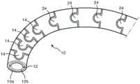
图1和1A示出了由具有两个管的单个嵌套组所形成的弯曲颈部的节段。Figures 1 and 1A show a segment of a curved neck formed by a single nested set of two tubes.
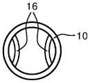
图2和2A示出了包括集成的控制缆线通道的由单个管所形成的弯曲颈部的节段。Figures 2 and 2A show a segment of a curved neck formed from a single tube including an integrated control cable channel.
图3示出了具有可变弯曲偏转点的本发明的弯曲颈部。Figure 3 shows a curved neck of the present invention with a variable curved deflection point.
图4示出了具有变化的链接件间距以提供可变铰接的弯曲颈部。Figure 4 shows a curved neck with varying link spacing to provide variable articulation.
图5是用于确定本发明的弯曲颈部的链接件到链接件的铰接角度的技术的详细视图。5 is a detailed view of a technique for determining the link-to-link hinge angle of the curved neck of the present invention.
图6示出了为本发明的弯曲颈部提供可变弯曲的可变硬度护套。Figure 6 shows a variable durometer sheath providing variable bending to the curved neck of the present invention.
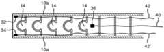
图7和图8示出了使用多个控制缆线锚固点来可控地改变本发明的弯曲颈部的弯曲。Figures 7 and 8 illustrate the use of multiple control cable anchorage points to controllably vary the curvature of the curved neck of the present invention.
图9示出了可以通过使用不同地锚固的控制缆线而在两个不同的平面中可控地弯曲的弯曲颈部。Figure 9 shows a curved neck that can be controllably flexed in two different planes by using differently anchored control cables.
图10a和10b示出了由一个平面中的两个弯曲节段可控铰接的可变铰接式弯曲颈部。Figures 10a and 10b show a variable articulating flex neck controllably articulated by two flex segments in one plane.
图11a和11b示出了由两个平面中的两个弯曲节段可控铰接的可变铰接式弯曲颈部。Figures 11a and 11b show a variably articulated curved neck that is controllably articulated by two curved segments in two planes.
具体实施方式Detailed ways
首先参照图1,示出了用于铰接式超声探头的单件弯曲颈部10,其由通常由诸如不锈钢的金属制成的两个同心管形成。内管10b紧密地装配在外管10a内。在插入之前,两个纵向沟槽12沿着管10b的外部长度形成在相对两侧上。这些沟槽形成用于控制缆线的通道,如下所述,这些控制缆线控制弯曲颈部的铰接。在图1A的横截面视图中清楚地示出了沟槽12。随着两个管同心定位,然后通过朝向管的纵向轴线的激光切割或通过另一种加工技术将这两个管切割成分开的链接件11。链接件被形成为例如通过从一个链接件延伸到下一个链接件并且位于链接件的相对两侧上的凸出部(lobe)14来保持彼此可移动地连接。在通过加工过程所形成的链接件之间的这些凸出部和间距使得相邻的链接件能够相对于彼此围绕穿过位于链接件的相对两侧上的相对的凸出部延伸的轴线而移动且枢转。虽然每个链接件只能相对于其邻接的链接件枢转较小的角度,但形成弯曲颈部的多个连续的链接件可以在相当大的曲线中一起弯曲。这是所期望的铰接,该铰接足以能够将探头的远侧端部定位在需要的位置上,但在任何铰接点处都不够急剧而以致约束穿过弯曲颈部的中央管腔的丝、工具及其它物品。Referring first to Figure 1, there is shown a single piece
图2示出了单件弯曲颈部的第二实施方式,此时仅使用单个管10。如上所述,将管10加工成分开的连接的链接件,在该附图中示出了分开的链接件之间的沟槽15。由于在该单个管实施方式中不存在用于控制缆线沟槽的内管,因此在管的相对两侧上形成一系列环状凹口16,以穿过弯曲颈部传送控制缆线。穿过管壁形成两个平行的切口,然后将切口之间的区域向内按压,形成如图2A的横截面图中清楚地示出的凹口。这些凹口形成在从枢转凸出部14形成的直线围绕管成90°的管侧上,这些凸出部位于顶部和底部上并且在图2的视图中不可见。由于在将控制缆线锚固在弯曲颈部的远侧端部之后,拉动穿过位于管的相对两侧上的凹口的控制缆线,所以这些控制缆线将分别导致颈部弯曲进入和出离图2的附图平面。Figure 2 shows a second embodiment of a one-piece curved neck, where only a
存在控制和调节本发明的弯曲颈部的弯曲的多种方式。一种控制技术是控制弯曲发生的偏转点。图3示出了一种技术,在该技术中刚性构件18位于弯曲颈部中并且该刚性构件的远侧端部位于所期望的偏转点处。在这种情况下,刚性构件是管18,并且该部分剖视图示出了管18的左侧的链接件,这些链接件可围绕其枢转凸出部自由枢转,而管所定位穿过的链接件被固定化而不能枢转。偏转点的位置可以通过调整刚性构件18伸入或伸出弯曲颈部的延伸部来调整。There are various ways of controlling and adjusting the curvature of the curved neck of the present invention. One control technique is to control the deflection point at which bending occurs. Figure 3 shows a technique in which the
如图4的弯曲颈部10所示,可以通过选择性地确定单独的链接件的长度来设定由弯曲颈部的节段的曲率所对应的角度。在该实施方式中,具有枢转凸出部14的左侧链接件相对较短并且这些链接件的长度可以以相对更短的曲率半径弯曲。具有枢转凸出部24的右侧较大的链接件将以相对更大的曲率半径最大地弯曲。另外,不同尺寸的链接件具有不同的力矩,这决定了当共同控制时,哪一组链接件将首先弯曲。具有较小力矩的枢转凸出部14的较小的链接件将首先弯曲。例如,当正控制着处于较小链接件的远侧末端(附图的左侧)的换能器的放置时,这是有用的。通过相对强力地持续拉动沟槽12中的控制缆线并且从而导致两个节段弯曲,将弯曲颈部的两个节段的铰接设置在大致所期望的位置。随着换能器靠近其所期望的位置,缆线的轻微拉动用于仅使较小链接件的远侧节段移动,以精细调整换能器的最终所期望的位置。As shown in the
相邻链接件之间的枢转程度是穿过管加工以形成分开的链接件的沟槽的函数。图5是弯曲颈部的一部分的部分侧视图,其中通过穿过管来加工沟槽15而已经形成分开的链接件11。两个链接件可以围绕枢转凸出部14以沟槽15的宽度枢转,这在枢转凸出部的轴线的每一侧上以90°打开和关闭沟槽。如果期望更大的枢转,则可以以在枢转凸出部上方和下方具有最大开口角度θ的锥形宽度来加工沟槽。因此相邻链接件的相对枢转由此增加到角度θ的尺度。The degree of pivoting between adjacent links is a function of the grooves machined through the tube to form the separate links. Figure 5 is a partial side view of a portion of the curved neck where the
用于提供弯曲颈部的可变弯曲的另一种技术是将弯曲颈部包裹在具有可变硬度的护套中。图6示出了覆于弯曲颈部上的护套20,该护套从弯曲颈部的左侧的远侧端部到近侧端部具有可变硬度。护套右侧相对较硬(硬度较高),而朝向护套的远侧端部则变得较软。当致动控制缆线以使弯曲颈部弯曲时,远侧端部将首先弯曲且比弯曲颈部的较高硬度的近侧节段更容易弯曲。硬度可以通过选择沿着护套的长度所使用的材料来设定。实现相同结果的另一种方式是沿着护套的长度改变护套材料的厚度。图6中的虚线22表示护套20朝向护套近侧(右侧)端部比朝向远侧端部和远侧端部处更厚。实现相同结果的另一种方式是通过将护套贴固在弯曲颈部上的方式。在图6的示例中,护套20沿着弯曲颈部的近侧部分在紧密间隔点26处固联到弯曲颈部,并且沿着弯曲颈部的远侧部分在更宽间隔点28处固联到弯曲颈部。这将导致弯曲颈部的远侧部分比近侧部分更容易且更轻易地弯曲。Another technique for providing variable bending of the curved neck is to wrap the curved neck in a sheath with variable stiffness. Figure 6 shows a
在一些实施方式中,在某些时候可能期望将弯曲颈部的节段可控地弯曲,并且在其它时候则期望将该节段锁定在不弯曲的构型中。图7示出了使用图4的实施例的该特征的实现方式。在这种情况下,存在穿过控制缆线通道12延伸的两组控制缆线40-40'和42-42'。如图8中的锚固点32和34所示,缆线42-42'的端部通过附接到弯曲颈部10的远侧链接件(最左侧)而锚固。在图8中,为了示出清楚而移除内管10b。如锚固点36和38所示,另一组缆线40-40'的端部锚固到链接件11',紧随具有枢转凸出部24的链接件的第一链接件。当以互补的方式拉动和松弛每对缆线时,弯曲颈部的对应节段在附图的平面中弯曲,缆线组42-42'控制远侧(小链接件)节段且缆线组40-40'控制近侧(较大链接件)节段。但是当一致地拉动两个缆线40-40'时,近侧节段的链接件被拉到一起并锁定为如图7所示的笔直的构型。弯曲颈部的远侧节段仍然可以通过使用缆线42-42'而可控地铰接。当一致地拉动缆线42和42'时,整个弯曲颈部锁定在笔直的构型中。因此,通过使用多个控制缆线和选定的锚固点,可以锁定或铰接弯曲颈部的不同节段。In some embodiments, it may be desirable at certain times to controllably bend the segment of the curved neck, and at other times it may be desirable to lock the segment in an unbent configuration. FIG. 7 shows an implementation of this feature using the embodiment of FIG. 4 . In this case, there are two sets of control cables 40 - 40 ′ and 42 - 42 ′ extending through the
在图7的实施方式中,枢转凸出部全都位于弯曲颈部的前部和后部,这允许两个铰接节段在相同的平面,即附图的平面中弯曲。单组控制缆线通道12容置用于该铰接的两组缆线。图9示出了其中枢转凸出部14形成在管的前侧和后侧并且因此其枢转轴线全部垂直于附图的平面的实施方式。然而,弯曲颈部的近侧节段的枢转凸出部24形成在管的顶部和底部上并且其枢转轴线平行于附图的平面。这意味着具有枢转凸出部14的远侧节段可以在附图的平面中弯曲,而链接件的近侧节段可以正交地弯曲进入或出离附图的平面。为了控制这些不同的动作,使用不同组的控制缆线。缆线42和42'穿过缆线通道12延伸并且在锚固点32和34处锚固在端部。这些缆线控制弯曲颈部的远侧(最左侧)节段的铰接。用于弯曲颈部的近侧节段的控制缆线40和40'从缆线42和42'围绕管的周向定向成90°。这些控制缆线必须穿过相对于通道12定向成90°的缆线自有的不同定位的控制缆线通道。如在图9的剖视图中由锚固在锚固点36上的缆线40所示,这些控制缆线40和40'锚固在它们控制的链接件的节段的远侧端部。(在该视图中,缆线40'及其锚固点被切除。)当拉动缆线42-42'时,链接件的远侧节段被铰接或锁定,并且当拉动缆线40-40'时,链接件的近侧节段被控制。In the embodiment of Figure 7, the pivoting lugs are all located at the front and rear of the curved neck, which allows the two articulation segments to bend in the same plane, the plane of the drawing. A single set of
图10a-10b是本发明的铰接式超声探头的透视图。该探头具有两个直的非铰接节段60和62以及两个铰接节段70和72。类似于图7的实现方式,铰接节段70和72铰接在相同平面内,即附图的水平平面H。在图10a中,短铰接节段70通过控制锚固在节段70的远侧端部处的缆线而弯曲。在图10b中,锚固在节段72的远侧端部处的缆线组已经用于铰接节段72。由于所有铰接位于相同的平面上,两个节段的枢转凸出部都位于节段的同一侧上,并且对于两个节段的控制缆线而言,仅需要单对缆线通道。10a-10b are perspective views of the articulating ultrasound probe of the present invention. The probe has two straight
图11a-11b是本发明的另一个铰接式超声探头的透视图,如图9的情况,该实施方式将铰接实施在两个平面上。类似图9,图11a的铰接节段72具有其枢转凸出部、枢转轴线以及控制缆线通道,该枢转凸出部、枢转轴线以及控制缆线通道与铰接节段70的枢转凸出部、枢转轴线以及控制缆线通道相比围绕管的周向定向成90°。如图11a和11b所示,远侧节段72可以在竖直(V)方向上可控地上下铰接。Figures 11a-11b are perspective views of another articulating ultrasound probe of the present invention, as in the case of Figure 9, this embodiment implements the articulation in two planes. Similar to FIG. 9 , the
对于本领域的技术人员而言,上述概念的其它变化可以轻易地实现。枢转凸出部可以形成为其他形状和尺寸,并且可以通过其他更复杂的销钉或铆钉配置来提供链接件之间的枢转。然而,本文所示的实施方式具有由单个或同心成对的管完全形成的优点。代替相同定向的链接件的节段,铰接节段可以穿插设有相对于彼此以90°枢转的链接件,从而赋予铰接节段能够在几乎任何方向上弯曲的能力。Other variations of the above-described concepts can readily be implemented by those skilled in the art. The pivoting projections can be formed in other shapes and sizes, and the pivoting between the links can be provided by other more complex pin or rivet arrangements. However, the embodiments shown herein have the advantage of being fully formed from a single or concentric pair of tubes. Instead of segments of identically oriented links, the hinged segments may be interspersed with links that pivot at 90° relative to each other, thereby giving the hinged segments the ability to bend in almost any direction.
Claims (11)
Translated fromChineseApplications Claiming Priority (3)
| Application Number | Priority Date | Filing Date | Title |
|---|---|---|---|
| US201562126752P | 2015-03-02 | 2015-03-02 | |
| US62/126,752 | 2015-03-02 | ||
| PCT/IB2016/050952WO2016139550A1 (en) | 2015-03-02 | 2016-02-23 | Single piece bending neck for an articulating ultrasound probe |
Publications (2)
| Publication Number | Publication Date |
|---|---|
| CN107405055A CN107405055A (en) | 2017-11-28 |
| CN107405055Btrue CN107405055B (en) | 2020-08-28 |
Family
ID=55524401
Family Applications (1)
| Application Number | Title | Priority Date | Filing Date |
|---|---|---|---|
| CN201680013261.4AActiveCN107405055B (en) | 2015-03-02 | 2016-02-23 | One-piece bending neck for articulating ultrasound probe |
Country Status (5)
| Country | Link |
|---|---|
| US (1) | US11707184B2 (en) |
| EP (2) | EP4417141A3 (en) |
| JP (1) | JP6785783B2 (en) |
| CN (1) | CN107405055B (en) |
| WO (1) | WO2016139550A1 (en) |
Families Citing this family (14)
| Publication number | Priority date | Publication date | Assignee | Title |
|---|---|---|---|---|
| JP6440860B2 (en)* | 2015-03-02 | 2018-12-19 | コーニンクレッカ フィリップス エヌ ヴェKoninklijke Philips N.V. | Variable configuration bending neck for articulating ultrasonic probes |
| CA3055378A1 (en)* | 2017-03-10 | 2018-09-13 | Georgia Tech Research Corporation | Systems and methods for steering guidewires |
| US10918268B2 (en)* | 2017-08-29 | 2021-02-16 | Opcom Inc. | Insert tube and endoscope using the same |
| CN108553070B (en)* | 2018-05-17 | 2020-09-18 | 黄琴 | Controllable bent pipe structure |
| GB2575675A (en)* | 2018-07-19 | 2020-01-22 | Imperial College Sci Tech & Medicine | A device |
| WO2020070851A1 (en)* | 2018-10-04 | 2020-04-09 | オリンパス株式会社 | Flexion part of endoscope |
| US11213309B2 (en)* | 2019-05-23 | 2022-01-04 | Biosense Webster (Israel) Ltd. | Medical probe having improved maneuverability |
| CA3149483A1 (en) | 2019-08-02 | 2021-02-11 | Vizaramed, Inc. | Steerable sheath |
| USD1039141S1 (en) | 2020-04-27 | 2024-08-13 | Acclarent, Inc. | Flex section in shaft for ENT instrument |
| CN113967032B (en)* | 2020-07-24 | 2025-03-04 | 深圳迈瑞生物医疗电子股份有限公司 | Floating device of ultrasonic equipment and ultrasonic equipment |
| CN113559395B (en)* | 2021-07-27 | 2023-04-25 | 西藏自治区人民政府驻成都办事处医院 | Balloon catheter special for BRTO and application method |
| CN115054805B (en)* | 2022-07-05 | 2025-07-25 | 深圳市库珀科技发展有限公司 | Bendable guiding sheath tube and guiding device |
| EP4302677A1 (en)* | 2022-07-08 | 2024-01-10 | Ambu A/S | A bending section for an endoscope |
| CN117860385B (en)* | 2023-02-03 | 2024-10-11 | 广州巧捷力医疗科技有限公司 | Steerable surgical arm with single cord for two curved segments and method of producing the same |
Family Cites Families (34)
| Publication number | Priority date | Publication date | Assignee | Title |
|---|---|---|---|---|
| DE3829603A1 (en)* | 1988-09-01 | 1990-03-15 | Kontron Holding Ag | ULTRASONIC DOSCOPE DEVICE |
| JP3143166B2 (en) | 1991-10-22 | 2001-03-07 | オリンパス光学工業株式会社 | Endoscope |
| JP3818693B2 (en)* | 1996-04-22 | 2006-09-06 | オリンパス株式会社 | Endoscope bending tube |
| US6887235B2 (en)* | 1999-03-24 | 2005-05-03 | Micrus Corporation | Variable stiffness heating catheter |
| JP2002177199A (en)* | 2000-10-02 | 2002-06-25 | Olympus Optical Co Ltd | Endoscope |
| US7250027B2 (en)* | 2002-05-30 | 2007-07-31 | Karl Storz Endovision, Inc. | Articulating vertebrae with asymmetrical and variable radius of curvature |
| JP2004105289A (en)* | 2002-09-13 | 2004-04-08 | Olympus Corp | Ultrasonic endoscope |
| US7410483B2 (en) | 2003-05-23 | 2008-08-12 | Novare Surgical Systems, Inc. | Hand-actuated device for remote manipulation of a grasping tool |
| JP2005040293A (en)* | 2003-07-28 | 2005-02-17 | Olympus Corp | Endoscope |
| CN1870930A (en) | 2003-08-20 | 2006-11-29 | 新引导系统公司 | Activated polymer articulated instruments and methods of insertion |
| WO2005113057A1 (en)* | 2004-05-17 | 2005-12-01 | C. R. Bard, Inc. | Articulated catheter |
| JP2005334050A (en) | 2004-05-24 | 2005-12-08 | Fujinon Corp | Angle section of endoscope |
| DE102004027850A1 (en) | 2004-06-08 | 2006-01-05 | Henke-Sass Wolf Gmbh | Bendable section of an introducer tube of an endoscope and method for its manufacture |
| JP4477519B2 (en) | 2005-02-14 | 2010-06-09 | オリンパス株式会社 | Endoscope |
| US8052597B2 (en)* | 2005-08-30 | 2011-11-08 | Boston Scientific Scimed, Inc. | Method for forming an endoscope articulation joint |
| JP2007236751A (en)* | 2006-03-10 | 2007-09-20 | Olympus Corp | Endoscope insertion section |
| JP2009528910A (en) | 2006-03-06 | 2009-08-13 | イマコー・エルエルシー | Transesophageal ultrasound probe with adjustable bending section |
| US8172758B2 (en) | 2006-03-06 | 2012-05-08 | Imacor Inc. | Transesophageal ultrasound probe with an adaptive bending section |
| JP2007307068A (en)* | 2006-05-17 | 2007-11-29 | Olympus Corp | Joint ring connecting body for insertion portion of endoscope and method for producing the same |
| JP2008259634A (en) | 2007-04-11 | 2008-10-30 | Olympus Corp | Connection structure of flexible tube for endoscope and annular connection member |
| JP2008295773A (en)* | 2007-05-31 | 2008-12-11 | Olympus Corp | Curved tube of endoscope, endoscope, and method for producing curved tube of endoscope |
| DE102009017175B4 (en)* | 2009-04-09 | 2011-05-05 | Richard Wolf Gmbh | Method for producing a bendable tube |
| JP5404154B2 (en)* | 2009-04-21 | 2014-01-29 | オリンパス株式会社 | Endoscope bending section and manufacturing method of bending tube |
| US9254123B2 (en) | 2009-04-29 | 2016-02-09 | Hansen Medical, Inc. | Flexible and steerable elongate instruments with shape control and support elements |
| DE102009042488A1 (en) | 2009-05-29 | 2010-12-02 | Aesculap Ag | Control device for use in endoscope, has proximal and distal end sections and center section, where proximal and distal end sections have articulated zone |
| US20100312056A1 (en)* | 2009-06-03 | 2010-12-09 | Gyrus, ACMI, Inc. | Endoscope shaft |
| JP2011067423A (en)* | 2009-09-25 | 2011-04-07 | Olympus Corp | Endoscope insertion part and manufacturing method of the same |
| US9474540B2 (en)* | 2009-10-08 | 2016-10-25 | Ethicon-Endo-Surgery, Inc. | Laparoscopic device with compound angulation |
| CN102413863A (en)* | 2009-10-14 | 2012-04-11 | 奥林巴斯医疗株式会社 | Flexible medical tube and insertion part of medical instrument |
| EP2732751A4 (en)* | 2011-12-06 | 2015-04-08 | Olympus Medical Systems Corp | FLEXIBLE JOINT |
| JP6082237B2 (en) | 2011-12-09 | 2017-02-15 | 株式会社トクヤマ | Manufacturing method of silicon substrate having texture structure |
| WO2013106444A1 (en)* | 2012-01-10 | 2013-07-18 | Boston Scientific Scimed, Inc. | A steerable medical device having an imaging system |
| US8967204B2 (en)* | 2012-08-24 | 2015-03-03 | Olympus Medical Systems Corporation | Curved pipe for endoscopes |
| EP3593700A1 (en) | 2014-12-05 | 2020-01-15 | Fortimedix Surgical B.V. | Method for manufacturing a steerable instrument and such steerable instrument |
- 2016
- 2016-02-23CNCN201680013261.4Apatent/CN107405055B/enactiveActive
- 2016-02-23EPEP24179860.2Apatent/EP4417141A3/enactivePending
- 2016-02-23WOPCT/IB2016/050952patent/WO2016139550A1/ennot_activeCeased
- 2016-02-23EPEP16709591.8Apatent/EP3264968B1/enactiveActive
- 2016-02-23USUS15/552,319patent/US11707184B2/enactiveActive
- 2016-02-23JPJP2017544963Apatent/JP6785783B2/enactiveActive
Also Published As
| Publication number | Publication date |
|---|---|
| EP4417141A2 (en) | 2024-08-21 |
| CN107405055A (en) | 2017-11-28 |
| EP4417141A3 (en) | 2024-12-18 |
| US11707184B2 (en) | 2023-07-25 |
| JP2018507053A (en) | 2018-03-15 |
| WO2016139550A1 (en) | 2016-09-09 |
| JP6785783B2 (en) | 2020-11-18 |
| EP3264968B1 (en) | 2024-09-25 |
| EP3264968A1 (en) | 2018-01-10 |
| US20180042451A1 (en) | 2018-02-15 |
Similar Documents
| Publication | Publication Date | Title |
|---|---|---|
| CN107405055B (en) | One-piece bending neck for articulating ultrasound probe | |
| US11452501B2 (en) | Variable configuration bending neck for an articulating ultrasound probe | |
| JP7692348B2 (en) | joint | |
| CN110913745B (en) | Curved section for endoscopes | |
| EP2874532B1 (en) | Elongate medical device with articulating portion | |
| EP1849396B1 (en) | Endoscope flexible tube, and endoscope device | |
| US20050209557A1 (en) | Defined deflection structure | |
| JP2012527918A (en) | Surgical instruments | |
| GB2456165A (en) | Slotted, flexible shaft for an endoscopic instrument | |
| TWI819471B (en) | A steerable arm for use in endoscopic surgical procedures | |
| JP6180679B2 (en) | Endoscope | |
| US20210321857A1 (en) | Articulated Segmented Instrument | |
| CN118178075A (en) | Cutting tube, sheath tube and conveying system | |
| EP3506839B1 (en) | Articulated meniscal repair instrument | |
| CN120788744A (en) | Steerable arm with sections curved in different planes |
Legal Events
| Date | Code | Title | Description |
|---|---|---|---|
| PB01 | Publication | ||
| PB01 | Publication | ||
| SE01 | Entry into force of request for substantive examination | ||
| SE01 | Entry into force of request for substantive examination | ||
| GR01 | Patent grant | ||
| GR01 | Patent grant |