CN107401979B - Vehicle body vibration displacement compensation device and method for catenary detection - Google Patents
Vehicle body vibration displacement compensation device and method for catenary detectionDownload PDFInfo
- Publication number
- CN107401979B CN107401979BCN201710645089.0ACN201710645089ACN107401979BCN 107401979 BCN107401979 BCN 107401979BCN 201710645089 ACN201710645089 ACN 201710645089ACN 107401979 BCN107401979 BCN 107401979B
- Authority
- CN
- China
- Prior art keywords
- displacement
- vehicle body
- rail
- laser
- relative
- Prior art date
- Legal status (The legal status is an assumption and is not a legal conclusion. Google has not performed a legal analysis and makes no representation as to the accuracy of the status listed.)
- Active
Links
- 238000006073displacement reactionMethods0.000titleclaimsabstractdescription170
- 238000001514detection methodMethods0.000titleclaimsabstractdescription76
- 238000000034methodMethods0.000titleclaimsabstractdescription24
- 238000005259measurementMethods0.000claimsabstractdescription90
- 238000007689inspectionMethods0.000claimsdescription14
- 238000003384imaging methodMethods0.000claimsdescription13
- 238000009434installationMethods0.000claimsdescription8
- 230000003287optical effectEffects0.000claimsdescription7
- 238000004364calculation methodMethods0.000claimsdescription5
- 238000012360testing methodMethods0.000claimsdescription4
- 230000009466transformationEffects0.000claimsdescription4
- 229910000831SteelInorganic materials0.000claimsdescription2
- 239000010959steelSubstances0.000claimsdescription2
- 230000001131transforming effectEffects0.000claims1
- 238000012423maintenanceMethods0.000description14
- 238000010586diagramMethods0.000description13
- 238000004590computer programMethods0.000description7
- 238000005516engineering processMethods0.000description7
- 238000012545processingMethods0.000description7
- 238000004458analytical methodMethods0.000description5
- 230000006870functionEffects0.000description4
- 238000010276constructionMethods0.000description3
- 230000008569processEffects0.000description3
- 238000007405data analysisMethods0.000description2
- 239000000284extractSubstances0.000description2
- 230000006872improvementEffects0.000description2
- 230000003993interactionEffects0.000description2
- 238000000691measurement methodMethods0.000description2
- 238000012986modificationMethods0.000description2
- 230000004048modificationEffects0.000description2
- 238000011160researchMethods0.000description2
- 230000003068static effectEffects0.000description2
- 241000271559DromaiidaeSpecies0.000description1
- 230000009286beneficial effectEffects0.000description1
- 230000008602contractionEffects0.000description1
- 238000013461designMethods0.000description1
- 238000011161developmentMethods0.000description1
- 238000003745diagnosisMethods0.000description1
- 230000007613environmental effectEffects0.000description1
- 230000003137locomotive effectEffects0.000description1
- 238000004519manufacturing processMethods0.000description1
- 238000013178mathematical modelMethods0.000description1
- 239000000725suspensionSubstances0.000description1
- 230000002194synthesizing effectEffects0.000description1
Images


Classifications
- G—PHYSICS
- G01—MEASURING; TESTING
- G01B—MEASURING LENGTH, THICKNESS OR SIMILAR LINEAR DIMENSIONS; MEASURING ANGLES; MEASURING AREAS; MEASURING IRREGULARITIES OF SURFACES OR CONTOURS
- G01B11/00—Measuring arrangements characterised by the use of optical techniques
- G01B11/02—Measuring arrangements characterised by the use of optical techniques for measuring length, width or thickness
- G01B11/022—Measuring arrangements characterised by the use of optical techniques for measuring length, width or thickness by means of tv-camera scanning
Landscapes
- Physics & Mathematics (AREA)
- General Physics & Mathematics (AREA)
- Length Measuring Devices By Optical Means (AREA)
Abstract
Translated fromChinese
Description
Translated fromChinese技术领域technical field
本发明涉及车辆检测领域,尤指一种用于接触网检测的车体振动位移补偿装置及方法。The invention relates to the field of vehicle detection, in particular to a vehicle body vibration displacement compensation device and method for catenary detection.
背景技术Background technique
随着铁路交通运输网络和城市轨道交通网络规模的不断扩大和日趋完善,铁路和城市轨道交通的相关运营维护部门的接触网检修任务也日益繁重。为有效提升铁路运输能力和运输效率,铁路运营维护部门必须在控制检修时间的同时有效提高检修作业的质量和效率,这就要求铁路运营维护部门采用更先进的检测技术和更科学的分析方法,从检测技术、检测精度等方面提高日常检修的效率,满足既有线路日常维护保养工作和新建线路的施工验收接管工作的需要。With the continuous expansion and improvement of the scale of the railway transportation network and the urban rail transit network, the maintenance tasks of the catenary of the relevant operation and maintenance departments of the railway and urban rail transit are also increasingly arduous. In order to effectively improve the railway transportation capacity and transportation efficiency, the railway operation and maintenance department must effectively improve the quality and efficiency of the maintenance operation while controlling the maintenance time. This requires the railway operation and maintenance department to adopt more advanced detection technology and more scientific analysis methods. Improve the efficiency of daily maintenance from the aspects of detection technology and detection accuracy, and meet the needs of daily maintenance of existing lines and construction acceptance of new lines.
接触网是电气化铁路和轨道交通的牵引供电系统的重要设备。电力机车通过受电弓与接触线滑动接触并获得电能。要保证电气化铁路和轨道交通的安全运营、保证弓网的良好接触和可靠取流,除了在接触网设计、施工和运营方面达到一定的规范要求外,还必须定期对接触网进行检测,以便及时发现并消除隐患。拉出值、导高等接触网几何参数是接触网检测的重要项目,需要定期进行检测以确认接触网技术状态。The catenary is an important equipment for the traction power supply system of electrified railway and rail transit. The electric locomotive is in sliding contact with the contact line through the pantograph and obtains electric energy. To ensure the safe operation of electrified railways and rail transit, and to ensure good contact and reliable flow of pantograph and catenary, in addition to meeting certain specification requirements in the design, construction and operation of the catenary, the catenary must also be inspected regularly to ensure timely Identify and eliminate hidden dangers. The geometric parameters of the catenary such as pull-out value and lead are important items of catenary inspection, and regular inspection is required to confirm the technical status of the catenary.
采用装备了接触网几何参数检测系统的专用车辆进行自动检测的方式具有测量精度和效率高、安全性好、不占用维修天窗、可等速测量以检测列车真实运行状态下的接触网技术状态等无可比拟的优势,代表着接触网检测技术的发展方向。接触网几何参数检测系统测量接触线的拉出值、导高和双支接触线相互位置等几何参数,既可运用于新建接触网工程联调联试,也可运用运营接触网设施周期性动态检测,是接触网检测系统的重要组成部分。由于拉出值和导高等几何参数以轨道顶平面作为测量基准,车载检测系统需进行车辆振动位移补偿测量,即测量车辆在动态运行过程中相对于轨道顶平面的空间姿态,实现将车辆坐标系下的几何参数测量结果还原至轨道坐标系下的测量结果。The automatic detection method using a special vehicle equipped with a catenary geometric parameter detection system has the advantages of high measurement accuracy and efficiency, good safety, no maintenance of the sunroof, and constant velocity measurement to detect the technical state of the catenary under the actual running state of the train, etc. Unparalleled advantages represent the development direction of catenary detection technology. The catenary geometric parameter detection system measures geometric parameters such as the pull-out value of the contact line, the lead height and the mutual position of the double contact lines. Detection is an important part of the catenary detection system. Since the geometric parameters such as pull-out value and lead are based on the top plane of the track, the on-board detection system needs to perform vehicle vibration displacement compensation measurement, that is, to measure the spatial attitude of the vehicle relative to the top plane of the track during dynamic operation, and realize the transformation of the vehicle coordinate system. The measurement results of the geometric parameters under the system are restored to the measurement results under the orbital coordinate system.
国内外相关科研机构和公司开展了车辆振动位移补偿技术的研究,发展了拉弦位移传感器、激光测距传感器等车体振动位移测量技术,并且建立了相应的车辆振动位移补偿数学模型。然而,从实际应用情况看,现有的车辆振动位移测量技术仍存在车载检测设备测量结果与现场测量结果存在一定偏差、拉弦位移传感器机械可靠性不高、安装于轴箱的机械装置存在一定安全隐患等不足。Relevant scientific research institutions and companies at home and abroad have carried out research on vehicle vibration displacement compensation technology, developed vehicle vibration displacement measurement technologies such as string displacement sensors and laser ranging sensors, and established corresponding vehicle vibration displacement compensation mathematical models. However, from the perspective of practical application, the existing vehicle vibration displacement measurement technology still has certain deviations between the measurement results of the on-board detection equipment and the on-site measurement results, the mechanical reliability of the string displacement sensor is not high, and the mechanical devices installed in the axle box have certain problems. Insufficient safety hazards, etc.
发明内容SUMMARY OF THE INVENTION
本发明目的在于提供一种能够在动态运行环境下实时准确测量车辆相对于轨平面的空间姿态,实现将车辆坐标系下的几何参数测量结果还原至轨道坐标系下的测量结果,提高接触网几何参数的测量精度,满足接触网施工质量检验和接触网运营状态技术诊断的需要的用于接触网检测的车体振动位移补偿装置。The purpose of the present invention is to provide a real-time and accurate measurement of the spatial attitude of the vehicle relative to the rail plane in a dynamic operating environment, so as to restore the measurement results of the geometric parameters in the vehicle coordinate system to the measurement results in the rail coordinate system, and improve the geometry of the catenary. The measurement accuracy of the parameters meets the needs of the catenary construction quality inspection and the technical diagnosis of the catenary operating state.
为达上述目的,本发明所提供的用于接触网检测的车体振动位移补偿装置,以检测车为搭载平台,具体包含:激光测量单元、位置确定模块、补偿参数确定模块、几何参数确定模块;所述激光测量单元安装于检测车的车底,用于获取检测车左右钢轨的二维位移数据;所述位置确定模块、所述补偿参数确定模块、所述几何参数确定模块安装于检测车内部,其中,所述位置确定模块用于根据所述二维位移数据计算获得所述左右钢轨相对所述激光测量单元的垂向位移和横向位移;所述补偿参数确定模块用于根据所述垂向位移和横向位移计算获得检测车相对于所述左右钢轨的车体振动位移补偿参数;所述几何参数确定模块用于获取的接触网几何参数测量值,并根据所述接触网几何参数测量值与车体振动位移补偿参数测量值,计算获得检测车相对于轨平面的接触网几何参数测量值。In order to achieve the above purpose, the vehicle body vibration displacement compensation device for catenary detection provided by the present invention takes the detection vehicle as a loading platform, and specifically includes: a laser measurement unit, a position determination module, a compensation parameter determination module, and a geometric parameter determination module. The laser measuring unit is installed on the bottom of the inspection vehicle to obtain the two-dimensional displacement data of the left and right rails of the inspection vehicle; the position determination module, the compensation parameter determination module, and the geometric parameter determination module are installed on the inspection vehicle Inside, wherein, the position determination module is used to calculate and obtain the vertical displacement and lateral displacement of the left and right rails relative to the laser measurement unit according to the two-dimensional displacement data; the compensation parameter determination module is used to Calculate the displacement and lateral displacement to obtain the vehicle body vibration displacement compensation parameters of the detection vehicle relative to the left and right rails; the geometric parameter determination module is used to obtain the measured values of the geometric parameters of the catenary, and according to the measured values of the geometric parameters of the catenary Combined with the measured values of the vibration and displacement compensation parameters of the vehicle body, the measured values of the geometric parameters of the catenary of the detection vehicle relative to the rail plane are obtained by calculation.
在上述用于接触网检测的车体振动位移补偿装置中,优选的,所述激光测量单元包含至少两个激光测量模块,所述激光测量模块包含线激光器和二维成像元件。In the above vehicle body vibration displacement compensation device for catenary detection, preferably, the laser measurement unit includes at least two laser measurement modules, and the laser measurement modules include a line laser and a two-dimensional imaging element.
在上述用于接触网检测的车体振动位移补偿装置中,优选的,所述激光测量模块位于左、右钢轨内侧上方并与垂直方向呈预定夹角。In the above vehicle body vibration displacement compensation device for catenary detection, preferably, the laser measurement module is located above the inner side of the left and right rails and forms a predetermined angle with the vertical direction.
在上述用于接触网检测的车体振动位移补偿装置中,优选的,所述激光测量模块的线激光器与二维成像元件沿线路纵向中心线前后布置,并且所述激光测量模块的线激光器产生的线激光位于与线路纵向中心线垂直的同一平面。In the above-mentioned vehicle body vibration displacement compensation device for catenary detection, preferably, the line laser of the laser measurement module and the two-dimensional imaging element are arranged back and forth along the longitudinal center line of the line, and the line laser of the laser measurement module generates The line laser is located in the same plane perpendicular to the longitudinal centerline of the line.
在上述用于接触网检测的车体振动位移补偿装置中,优选的,所述激光测量单元还包含遮光罩,所述遮光罩设置于钢轨上方并固定于车体底部,用于减少或阻止太阳光照射钢轨对激光测量造成干扰。In the above-mentioned vehicle body vibration displacement compensation device for catenary detection, preferably, the laser measurement unit further includes a light shield, and the light shield is arranged above the steel rail and fixed at the bottom of the vehicle body for reducing or preventing sunlight. Light shining on the rail interferes with the laser measurement.
在上述用于接触网检测的车体振动位移补偿装置中,优选的,所述激光测量单元和所述遮光罩位于与线路纵向中心线垂直的同一断面,且固定于检测车底或固定于检测车底与线路纵向中心线垂直的一根水平布置的检测梁。In the above-mentioned vehicle body vibration displacement compensation device for catenary detection, preferably, the laser measuring unit and the light shield are located in the same section perpendicular to the longitudinal centerline of the line, and are fixed on the bottom of the detection vehicle or fixed on the detection A horizontally arranged detection beam with the bottom of the vehicle perpendicular to the longitudinal centerline of the line.
在上述用于接触网检测的车体振动位移补偿装置中,优选的,所述位置确定模块包括旋转变换单元和特征识别单元;所述旋转变换单元根据激光测量模块相对于垂直方向的安装倾角将二维位移数据旋转变换为相对车底安装平面的二维位移数据;所述特征识别单元根据钢轨轮廓特征依次确定钢轨轨顶面位置、轨距点位置和轨顶点位置,并根据所述钢轨轨顶面位置、轨距点位置和轨顶点位置获得钢轨相对激光测量模块的垂向位移和横向位移。In the above-mentioned vehicle body vibration displacement compensation device for catenary detection, preferably, the position determination module includes a rotation transformation unit and a feature identification unit; The two-dimensional displacement data is rotated and transformed into two-dimensional displacement data relative to the installation plane of the vehicle bottom; the feature identification unit sequentially determines the top surface position of the rail rail, the position of the gauge point and the position of the rail vertex according to the profile features of the rail, and according to the rail rail The vertical and lateral displacements of the rail relative to the laser measurement module are obtained from the position of the top surface, the position of the gauge point and the position of the rail vertex.
本发明还提供一种用于接触网检测的车体振动位移补偿方法,所述方法具体包含:获取检测车左右钢轨的二维位移数据;根据所述二维位移数据计算获得所述左右钢轨相对所述激光测量单元的垂向位移和横向位移;根据所述垂向位移和横向位移计算获得检测车相对于所述左右钢轨的车体振动位移补偿参数;获取的接触网几何参数测量值,并根据所述接触网几何参数测量值与车体振动位移补偿参数测量值,计算获得检测车相对于轨平面的接触网几何参数测量值。The present invention also provides a vehicle body vibration displacement compensation method for catenary detection, the method specifically includes: acquiring two-dimensional displacement data of the left and right rails of the detection vehicle; The vertical displacement and lateral displacement of the laser measuring unit; according to the vertical displacement and lateral displacement, the compensation parameters of the vehicle body vibration displacement of the detection vehicle relative to the left and right rails are obtained; the obtained measurement values of the geometric parameters of the catenary are obtained and According to the measured value of the geometrical parameter of the catenary and the measured value of the vibration displacement compensation parameter of the vehicle body, the measured value of the geometrical parameter of the catenary of the detection vehicle relative to the rail plane is obtained by calculation.
在上述用于接触网检测的车体振动位移补偿方法中,优选的,所述车体振动位移补偿参数包括车体侧倾角度、车体相对轨平面的横向位移和垂向位移。In the above vehicle body vibration displacement compensation method for catenary detection, preferably, the vehicle body vibration displacement compensation parameters include vehicle body roll angle, lateral displacement and vertical displacement of the vehicle body relative to the rail plane.
在上述用于接触网检测的车体振动位移补偿方法中,优选的,所述车体侧倾角度和车体相对轨平面的垂向位移还包含:根据激光测量单元分别相对左、右钢轨的垂向位移获得车体侧倾角度和车体相对轨平面的垂向位移。In the above-mentioned vehicle body vibration displacement compensation method for catenary detection, preferably, the vehicle body roll angle and the vertical displacement of the vehicle body relative to the rail plane further include: The vertical displacement obtains the roll angle of the car body and the vertical displacement of the car body relative to the rail plane.
在上述用于接触网检测的车体振动位移补偿方法中,优选的,所述车体相对轨平面的横向位移还包含:根据激光测量单元分别相对左、右钢轨的横向位移获得车体相对轨平面的横向位移。In the above-mentioned vehicle body vibration displacement compensation method for catenary detection, preferably, the lateral displacement of the vehicle body relative to the rail plane further comprises: obtaining the relative rail of the vehicle body according to the lateral displacement of the laser measuring unit relative to the left and right rails respectively. Lateral displacement of the plane.
本发明的测量装置不受车辆运行速度的限制,既可以对新建线路接触网进行低速静态检测,也可以对包括高速铁路在内的运营线路接触网进行与线路运营速度一致的等速测量以检验列车真实运行状态下的接触网技术状态,检测结果准确,检测效率高,不占用维修天窗时间,为接触网几何参数测量提供了一种可靠的车体振动位移补偿手段,提升了供电设备检查和维护的工作效率。The measuring device of the present invention is not limited by the running speed of the vehicle, and can not only perform low-speed static detection on the catenary of newly-built lines, but also perform constant-speed measurement on the catenary of operating lines including high-speed railways that is consistent with the operating speed of the line to check The technical status of the catenary under the actual running state of the train, the detection results are accurate, the detection efficiency is high, and the maintenance skylight time is not occupied. It provides a reliable vehicle body vibration displacement compensation method for the measurement of the geometric parameters of the catenary, and improves the inspection and maintenance of the power supply equipment. Maintenance work efficiency.
为让本发明的上述和其他目的、特征和优点能更明显易懂,下文特举较佳实施例,并配合所附图式,作详细说明如下。In order to make the above-mentioned and other objects, features and advantages of the present invention more obvious and easy to understand, the preferred embodiments are exemplified below, and are described in detail as follows in conjunction with the accompanying drawings.
附图说明Description of drawings
为了更清楚地说明本发明实施例或现有技术中的技术方案,下面将对实施例或现有技术描述中所需要使用的附图作简单地介绍,显而易见地,下面描述中的附图仅仅是本发明的一些实施例,对于本领域普通技术人员来讲,在不付出创造性劳动的前提下,还可以根据这些附图获得其他的附图;In order to explain the embodiments of the present invention or the technical solutions in the prior art more clearly, the following briefly introduces the accompanying drawings that need to be used in the description of the embodiments or the prior art. Obviously, the accompanying drawings in the following description are only These are some embodiments of the present invention. For those of ordinary skill in the art, other drawings can also be obtained from these drawings without creative work;
图1为本发明提供的一种用于接触网检测的车体振动位移补偿装置的框图;1 is a block diagram of a vehicle body vibration displacement compensation device for catenary detection provided by the present invention;
图2为本发明实施例中的装置结构示意图;2 is a schematic structural diagram of an apparatus in an embodiment of the present invention;
图3为本发明实施例中的车体振动位移补偿装置的框图;3 is a block diagram of a vehicle body vibration displacement compensation device in an embodiment of the present invention;
图4为本发明实施例中的激光测量单元的原理示意图;4 is a schematic diagram of the principle of a laser measurement unit in an embodiment of the present invention;
图5为本发明实施例中的一种用于接触网检测的车体振动位移补偿方法流程示意图;5 is a schematic flowchart of a vehicle body vibration displacement compensation method for catenary detection according to an embodiment of the present invention;
图6为本发明实施例中的车体振动位移补偿检测软件流程示意图;6 is a schematic flowchart of a vehicle body vibration and displacement compensation detection software in an embodiment of the present invention;
图7为本发明实施例中的车体振动位移补偿检测软件模块示意图。FIG. 7 is a schematic diagram of a software module of vehicle body vibration and displacement compensation detection in an embodiment of the present invention.
具体实施方式Detailed ways
为使本发明实施例的目的、技术方案和优点更加清楚明白,下面结合实施例和附图,对本发明做进一步详细说明。在此,本发明的示意性实施例及其说明用于解释本发明,但并不作为对本发明的限定。In order to make the purposes, technical solutions and advantages of the embodiments of the present invention more clear, the present invention will be further described in detail below with reference to the embodiments and the accompanying drawings. Here, the exemplary embodiments of the present invention and their descriptions are used to explain the present invention, but not to limit the present invention.
本发明提供一种用于接触网检测的车体振动位移补偿装置,如图1所示,该装置以检测车为搭载平台;该装置包括:激光测量单元1、位置确定模块2、补偿参数确定模块3、几何参数确定模块4;激光测量单元1安装于检测车的车底;位置确定模块2、补偿参数确定模块3、几何参数确定模块4安装于检测车内部;The present invention provides a vehicle body vibration displacement compensation device for catenary detection. As shown in FIG. 1 , the device uses a detection vehicle as a mounting platform; the device includes: a
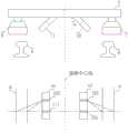
其中,如图2所示,激光测量单元1用于:包括至少两台激光测量模块11、12分别固定于车辆底部左右两侧,分别获取左、右钢轨8、9的二维位移数据;Wherein, as shown in FIG. 2 , the
位置确定模块2用于:分别对左、右钢轨8、9的二维位移数据进行数据分析提取钢轨相对激光传感器11、12的垂向位移和横向位移;The
补偿参数确定模块3用于:根据两台激光测量单元11、12分别相对左、右钢轨8、9的垂向、横向位移确定车辆相对于两轨轨平面的车体振动位移补偿参数;The compensation
几何参数确定模块4用于:将车顶传感器获取的接触网几何参数测量值与车体振动位移补偿参数测量值合成计算获取相对于轨平面的接触网几何参数测量值。The geometric
如图2所示,激光测量单元1包括左、右两个激光测量模块11、12,左激光测量模块11由线激光器111和二维成像元件112组成,右激光测量模块12由线激光器121和二维成像元件122组成。As shown in FIG. 2 , the
左、右两个激光测量模块11、12位于左、右钢轨8、9内侧上方并与垂直方向呈一定夹角θ,通常激光测量模块与垂直方向的夹角θ设置为45°或30°。The left and right
如图2所示,激光测量模块11、12的线激光器111、121与二维成像元件112、122沿线路纵向中心线前后布置,并且两台激光测量模块11、12的线激光器111、121产生的线激光位于与线路纵向中心线垂直的同一平面,从而保证在同一个空间断面内测量车体相对钢轨轨平面的空间姿态参数。As shown in FIG. 2 , the
为了有效减少或阻止太阳光照射钢轨对激光测量造成干扰,每个激光测量模块11、12分别采用一个遮光罩6、7,将遮光罩固定于车体底部并位于左、右钢轨8、9上方,有效保证了各种环境条件下进行可靠的光学测量。In order to effectively reduce or prevent the interference of sunlight on the rails to the laser measurement, each
进一步的,如图2所示,两台激光测量模块11、12和两个遮光罩6、7位于与线路纵向中心线垂直的同一断面,可分别固定于车体底部或统一固定于与线路纵向中心线垂直的一根水平布置的检测梁5。本实施例中采用检测梁5作为两台激光测量模块11、12和两个遮光罩6、7的安装基准,易于实现保证线激光器111、121产生的线激光位于与线路纵向中心线垂直的同一平面的测量要求。光学梁5通过顶部的机械组件和紧固件与车底进行机械连接,可以适用于动车组、单节接触网检测车、接触网作业车等各种车辆。Further, as shown in Figure 2, the two
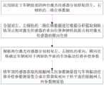
本实施例的用于接触网检测的车体振动位移补偿装置的详细框图如图3所示。首先,两台激光测量模块11、12分别获取左、右钢轨8、9的二维位移数据,其原理如图4所示。以右侧激光测量模块12获取钢轨9的二维位移数据为例,右侧激光测量模块12的线激光器121将投射出垂直于线路纵向中心线的一束线结构光至右侧钢轨9的上表面和内侧面,线结构光为一窄的激光平面,其与右侧钢轨9表面相交时便在右侧钢轨9表面产生一亮的光条,该光条由被测物体即右侧钢轨9表面形状所调制,从而形成了右侧钢轨9的光条三维图像。该三维图像被沿线路纵向中心线方向与线激光器121呈前后布置、并与线激光器121相距一定距离的二维成像元件122所探测,从而获得光条的二维畸变图像。光条的畸变成图取决于线激光器121和二维成像组件122之间的相对位置和右侧钢轨9表面形廓。当线激光器121和二维成像组件122之间的相对位置一定并且线激光器121垂直于右侧钢轨9表面投射时,通过光学标定可由二维光条图像获得右侧钢轨9相对线激光器121的二维位移数据。A detailed block diagram of the vehicle body vibration and displacement compensation device for catenary detection in this embodiment is shown in FIG. 3 . First, the two
如图3所示,两台激光测量模块11、12分别获取左、右钢轨8、9的二维位移数据,经位置确定模块2的数据采集卡21采集并传输至旋转变换单元22,旋转变换单元22根据激光测量模块11、12相对于垂直方向的安装倾角θ将左、右钢轨8、9的二维位移数据旋转变换为相对车底安装平面的二维位移数据。特征识别单元23对旋转后的二维位移数据进行分析,根据钢轨轮廓特征依次确定钢轨轨顶面位置、轨距点位置和轨顶点位置,提取左、右钢轨8、9相对激光测量模块11、12的垂向位移和横向位移。As shown in FIG. 3 , the two
补偿参数确定模块3根据位置确定模块2输出的垂向位移和横向位移确定车辆相对于两轨轨平面的车体振动位移补偿参数包括车体侧倾角度、车体相对轨平面的横向位移和垂向位移。其中,根据两台激光测量模块分别相对左、右钢轨的垂向位移获得车体相对轨平面的侧倾角度和垂向位移;根据两台激光测量模块分别相对左、右钢轨的横向位移获得车体相对轨平面的横向位移。The compensation
几何参数确定模块4根据补偿参数确定模块3输出的车辆振动位移补偿数据和车顶传感器10获取的接触网几何参数测量值进行合成计算,获取相对于轨平面的接触网几何参数测量值。The geometric
本发明还提供一种用于接触网检测的车体振动位移补偿方法,所述方法具体包含:获取检测车左右钢轨的二维位移数据;根据所述二维位移数据计算获得所述左右钢轨相对所述激光测量单元的垂向位移和横向位移;根据所述垂向位移和横向位移计算获得检测车相对于所述左右钢轨的车体振动位移补偿参数;获取的接触网几何参数测量值,并根据所述接触网几何参数测量值与车体振动位移补偿参数测量值,计算获得检测车相对于轨平面的接触网几何参数测量值。其中,所述车体振动位移补偿参数包括车体侧倾角度、车体相对轨平面的横向位移和垂向位移,根据激光测量单元分别相对左、右钢轨的垂向位移获得车体相对轨平面的侧倾角度和垂向位移;根据激光测量单元分别相对左、右钢轨的横向位移获得车体相对轨平面的横向位移。The present invention also provides a vehicle body vibration displacement compensation method for catenary detection, the method specifically includes: acquiring two-dimensional displacement data of the left and right rails of the detection vehicle; The vertical displacement and lateral displacement of the laser measuring unit; according to the vertical displacement and lateral displacement, the compensation parameters of the vehicle body vibration displacement of the detection vehicle relative to the left and right rails are obtained; the obtained measurement values of the geometric parameters of the catenary are obtained and According to the measured value of the geometrical parameter of the catenary and the measured value of the vibration displacement compensation parameter of the vehicle body, the measured value of the geometrical parameter of the catenary of the detection vehicle relative to the rail plane is obtained by calculation. The vehicle body vibration displacement compensation parameters include the vehicle body roll angle, the lateral displacement and vertical displacement of the vehicle body relative to the rail plane, and the relative rail plane of the vehicle body is obtained according to the vertical displacement of the laser measurement unit relative to the left and right rails respectively. The lateral displacement of the car body relative to the rail plane is obtained according to the lateral displacement of the laser measuring unit relative to the left and right rails, respectively.
上述实施例的具体实施流程请参考图5所示:Please refer to Figure 5 for the specific implementation process of the above embodiment:
(1)运用固定于车辆底部的两台激光传感器分别获取的左、右钢轨的二维位移数据;(1) The two-dimensional displacement data of the left and right rails respectively obtained by two laser sensors fixed at the bottom of the vehicle;
(2)分别对左、右钢轨的二维位移数据进行数据分析提取钢轨轨顶点相对激光传感器的垂向位移和钢轨轨距点相对激光传感器的横向位移;(2) Perform data analysis on the two-dimensional displacement data of the left and right rails to extract the vertical displacement of the rail vertex relative to the laser sensor and the lateral displacement of the rail gauge point relative to the laser sensor;
(3)根据两台激光传感器分别相对左、右钢轨的垂向、横向位移确定车辆相对于两轨轨平面的车体振动位移补偿参数;(3) According to the vertical and lateral displacements of the two laser sensors relative to the left and right rails, respectively, determine the vehicle body vibration displacement compensation parameters relative to the two rail planes;
(4)将车顶传感器获取的接触网几何参数测量值与车体振动位移补偿参数测量值合成计算获取相对于轨平面的接触网几何参数测量值。(4) The measured values of the catenary geometric parameters obtained by the roof sensor and the measured values of the vehicle body vibration displacement compensation parameters are synthesized and calculated to obtain the measured values of the catenary geometric parameters relative to the rail plane.
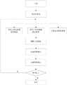
本实施例的车体振动位移补偿参数检测流程如图6所示,图7为本实施例的车体振动位移补偿参数检测软件模块示意图。The process of detecting the vehicle body vibration and displacement compensation parameters in this embodiment is shown in FIG. 6 , and FIG. 7 is a schematic diagram of the software module for detecting the vehicle body vibration and displacement compensation parameters in this embodiment.
在图6中,首先初始化所述车体振动位移补偿装置内数据,然后采集左激光测量模块、右激光测量模块和速度里程数据,根据上述三组数据确定钢轨的位置,根据钢轨位置进一步确定补偿参数和几何参数,判断当前补偿工作中数据有效性,如有效,停止采集数据并通过补偿参数和几何参数进行车体振动位移补偿。In Fig. 6, first initialize the data in the vehicle body vibration displacement compensation device, then collect the left laser measurement module, right laser measurement module and speed mileage data, determine the position of the rail according to the above three sets of data, and further determine the compensation according to the position of the rail Parameters and geometric parameters, judge the validity of the data in the current compensation work, if it is valid, stop collecting data and perform vehicle body vibration displacement compensation through compensation parameters and geometric parameters.
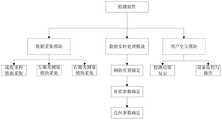
在图7中利用检测元件控制数据采集模块、数据实时处理模块和用户交互模块配合执行车体振动位移补偿,其中数据采集模块主要控制左激光测量模块、右激光测量模块和速度里程数据的采集,其后将采集到的数据传输至数据实时处理模块,数据实时处理模块再进行钢轨位置分析、补偿参数分析和几何参数分析,最后再利用用户交互模块,例如显示屏等设备将分析获得的车体振动位移补偿数据显示输出,供用户进行设备监控或操作。In Fig. 7, the detection element is used to control the data acquisition module, the data real-time processing module and the user interaction module to perform the vehicle body vibration and displacement compensation. The data acquisition module mainly controls the left laser measurement module, the right laser measurement module and the collection of speed and mileage data. Then, the collected data is transmitted to the data real-time processing module, and the data real-time processing module then performs rail position analysis, compensation parameter analysis and geometric parameter analysis, and finally uses the user interaction module, such as the display screen and other equipment to analyze the obtained car body. Vibration displacement compensation data display output for users to monitor or operate the equipment.
本实施例的用于接触网检测的车体振动位移补偿装置,利用激光测量技术进行光学非接触式的空间位移测量。传统的拉弦式位移传感器测量方式以轮轨紧密接触为前提,通过测量车体相对轴箱偏移来间接反映车体相对钢轨的位移,与之相比,本发明的测量方式直接获取车体在运用过程中相对轨道出现的侧滚、横摆、沉浮而产生的水平方向和垂直方向的位移量,测量直接准确,避免了车辆运行时的轮轨游间变化对测量结果的影响。本发明的测量装置不包含车下机械可动部件,避免了传统的拉弦式位移传感器拉弦反复伸缩发生断裂等失效风险,避免了对车辆轴箱结构进行改造以安装拉弦位移传感器的悬挂点,降低了行车安全风险。本发明的测量装置直接获取钢轨部分轮廓的连续二维位移数据,通过分析可准确提取钢轨相对激光传感器的垂向位移和横向位移,克服了传统的点式激光测距传感器无法准确定位钢轨特征点并获取准确位移信息的不足。The vehicle body vibration displacement compensation device for catenary detection in this embodiment uses laser measurement technology to perform optical non-contact spatial displacement measurement. The traditional measurement method of the string-pulling displacement sensor is based on the premise that the wheel and rail are in close contact, and the displacement of the vehicle body relative to the rail is indirectly reflected by measuring the offset of the vehicle body relative to the axle box. Compared with this, the measurement method of the present invention directly obtains the vehicle body. The displacement in the horizontal and vertical directions caused by the roll, yaw, and ups and downs of the track during operation can be measured directly and accurately, avoiding the influence of wheel-rail travel changes during vehicle operation on the measurement results. The measuring device of the present invention does not include mechanical movable parts under the vehicle, avoids the failure risks of the traditional string-pulling displacement sensor, such as the repeated expansion and contraction of the string, and avoids the modification of the vehicle axle box structure to install the suspension of the string-pulling displacement sensor. point, reducing the risk of driving safety. The measuring device of the invention directly obtains the continuous two-dimensional displacement data of the profile of the rail part, and can accurately extract the vertical displacement and lateral displacement of the rail relative to the laser sensor through analysis, and overcomes the inability of the traditional point-type laser ranging sensor to accurately locate the characteristic points of the rail And the insufficiency of obtaining accurate displacement information.
本实施例的测量装置不受车辆运行速度的限制,既可以对新建线路接触网进行低速静态检测,也可以对包括高速铁路在内的运营线路接触网进行与线路运营速度一致的等速测量以检验列车真实运行状态下的接触网技术状态,检测结果准确,检测效率高,不占用维修天窗时间,为接触网几何参数测量提供了一种可靠的车体振动位移补偿手段,提升了供电设备检查和维护的工作效率。The measuring device of this embodiment is not limited by the running speed of the vehicle. It can perform low-speed static detection on the catenary of the newly-built line, and can measure the catenary of the operating line, including the high-speed railway, at a constant speed consistent with the operating speed of the line. Test the technical status of the catenary under the actual running state of the train, the detection results are accurate, the detection efficiency is high, and the maintenance skylight time is not occupied. It provides a reliable vehicle body vibration displacement compensation method for the measurement of the geometric parameters of the catenary, and improves the inspection of power supply equipment. and maintenance efficiency.
本领域内的技术人员应明白,本发明的实施例可提供为方法、系统、或计算机程序产品。因此,本发明可采用完全硬件实施例、完全软件实施例、或结合软件和硬件方面的实施例的形式。而且,本发明可采用在一个或多个其中包含有计算机可用程序代码的计算机可用存储介质(包括但不限于磁盘存储器、CD-ROM、光学存储器等)上实施的计算机程序产品的形式。As will be appreciated by one skilled in the art, embodiments of the present invention may be provided as a method, system, or computer program product. Accordingly, the present invention may take the form of an entirely hardware embodiment, an entirely software embodiment, or an embodiment combining software and hardware aspects. Furthermore, the present invention may take the form of a computer program product embodied on one or more computer-usable storage media (including, but not limited to, disk storage, CD-ROM, optical storage, etc.) having computer-usable program code embodied therein.
本发明是参照根据本发明实施例的方法、设备(系统)、和计算机程序产品的流程图和/或方框图来描述的。应理解可由计算机程序指令实现流程图和/或方框图中的每一流程和/或方框、以及流程图和/或方框图中的流程和/或方框的结合。可提供这些计算机程序指令到通用计算机、专用计算机、嵌入式处理机或其他可编程数据处理设备的处理器以产生一个机器,使得通过计算机或其他可编程数据处理设备的处理器执行的指令产生用于实现在流程图一个流程或多个流程和/或方框图一个方框或多个方框中指定的功能的装置。The present invention is described with reference to flowchart illustrations and/or block diagrams of methods, apparatus (systems), and computer program products according to embodiments of the invention. It will be understood that each flow and/or block in the flowchart illustrations and/or block diagrams, and combinations of flows and/or blocks in the flowchart illustrations and/or block diagrams, can be implemented by computer program instructions. These computer program instructions may be provided to the processor of a general purpose computer, special purpose computer, embedded processor or other programmable data processing device to produce a machine such that the instructions executed by the processor of the computer or other programmable data processing device produce Means for implementing the functions specified in a flow or flow of a flowchart and/or a block or blocks of a block diagram.
这些计算机程序指令也可存储在能引导计算机或其他可编程数据处理设备以特定方式工作的计算机可读存储器中,使得存储在该计算机可读存储器中的指令产生包括指令装置的制造品,该指令装置实现在流程图一个流程或多个流程和/或方框图一个方框或多个方框中指定的功能。These computer program instructions may also be stored in a computer-readable memory capable of directing a computer or other programmable data processing apparatus to function in a particular manner, such that the instructions stored in the computer-readable memory result in an article of manufacture comprising instruction means, the instructions The apparatus implements the functions specified in the flow or flow of the flowcharts and/or the block or blocks of the block diagrams.
这些计算机程序指令也可装载到计算机或其他可编程数据处理设备上,使得在计算机或其他可编程设备上执行一系列操作步骤以产生计算机实现的处理,从而在计算机或其他可编程设备上执行的指令提供用于实现在流程图一个流程或多个流程和/或方框图一个方框或多个方框中指定的功能的步骤。These computer program instructions can also be loaded on a computer or other programmable data processing device to cause a series of operational steps to be performed on the computer or other programmable device to produce a computer-implemented process such that The instructions provide steps for implementing the functions specified in the flow or blocks of the flowcharts and/or the block or blocks of the block diagrams.
以上所述的具体实施例,对本发明的目的、技术方案和有益效果进行了进一步详细说明,所应理解的是,以上所述仅为本发明的具体实施例而已,并不用于限定本发明的保护范围,凡在本发明的精神和原则之内,所做的任何修改、等同替换、改进等,均应包含在本发明的保护范围之内。The specific embodiments described above further describe the purpose, technical solutions and beneficial effects of the present invention in detail. It should be understood that the above-mentioned specific embodiments are only specific embodiments of the present invention, and are not intended to limit the scope of the present invention. Any modification, equivalent replacement, improvement, etc. made within the spirit and principle of the present invention shall be included within the protection scope of the present invention.
Claims (9)
Translated fromChinesePriority Applications (1)
| Application Number | Priority Date | Filing Date | Title |
|---|---|---|---|
| CN201710645089.0ACN107401979B (en) | 2017-08-01 | 2017-08-01 | Vehicle body vibration displacement compensation device and method for catenary detection |
Applications Claiming Priority (1)
| Application Number | Priority Date | Filing Date | Title |
|---|---|---|---|
| CN201710645089.0ACN107401979B (en) | 2017-08-01 | 2017-08-01 | Vehicle body vibration displacement compensation device and method for catenary detection |
Publications (2)
| Publication Number | Publication Date |
|---|---|
| CN107401979A CN107401979A (en) | 2017-11-28 |
| CN107401979Btrue CN107401979B (en) | 2020-06-05 |
Family
ID=60402639
Family Applications (1)
| Application Number | Title | Priority Date | Filing Date |
|---|---|---|---|
| CN201710645089.0AActiveCN107401979B (en) | 2017-08-01 | 2017-08-01 | Vehicle body vibration displacement compensation device and method for catenary detection |
Country Status (1)
| Country | Link |
|---|---|
| CN (1) | CN107401979B (en) |
Families Citing this family (10)
| Publication number | Priority date | Publication date | Assignee | Title |
|---|---|---|---|---|
| CN108827204A (en)* | 2018-08-09 | 2018-11-16 | 东莞市诺丽电子科技有限公司 | A kind of contact net geometric parameter method for compensating vibration |
| CN109238149B (en)* | 2018-09-25 | 2019-12-13 | 北京华开领航科技有限责任公司 | Vehicle body attitude detection device and contact line dynamic offset detection system |
| CN109341573A (en)* | 2018-09-30 | 2019-02-15 | 中国铁建重工集团有限公司 | A kind of tunnel-liner profile Clearance Detection |
| CN112843633A (en)* | 2021-01-09 | 2021-05-28 | 吉首大学 | Body training balance ball and control method thereof |
| CN113009456B (en)* | 2021-02-22 | 2023-12-05 | 中国铁道科学研究院集团有限公司 | Vehicle-mounted laser radar data calibration method, device and system |
| CN114088434A (en)* | 2021-11-18 | 2022-02-25 | 南京铁道职业技术学院 | System and method for detecting wheel axle vibration of urban rail vehicle based on laser ranging |
| CN114862950A (en)* | 2022-04-26 | 2022-08-05 | 成都唐源电气股份有限公司 | Vehicle body vibration compensation parameter detection method and system based on plane rectangular coordinate system |
| CN115236682B (en)* | 2022-07-09 | 2024-04-26 | 江苏新绿能科技有限公司 | Improved overhead line system vehicle-mounted limit measurement method based on machine vision |
| CN116147489B (en)* | 2023-04-04 | 2023-07-04 | 成都弓网科技有限责任公司 | Detachable self-compensating line intrusion detection method and device |
| CN119123987B (en)* | 2024-11-14 | 2025-01-28 | 东莞市诺丽科技股份有限公司 | Contact net-track cooperative comprehensive inspection system and method thereof |
Citations (7)
| Publication number | Priority date | Publication date | Assignee | Title |
|---|---|---|---|---|
| JPH08327336A (en)* | 1995-06-02 | 1996-12-13 | Technol Res Assoc Of Medical & Welfare Apparatus | Three dimensional shape-measuring apparatus |
| CN1754667A (en)* | 2004-09-28 | 2006-04-05 | 株式会社三协精机制作所 | Programme,tape box,location tester for instructing robot, and robot woring method |
| CN104296682A (en)* | 2014-10-28 | 2015-01-21 | 电子科技大学 | Contour registration method used in train guide rail contour measurement based on machine vision |
| CN106080661A (en)* | 2016-05-27 | 2016-11-09 | 电子科技大学 | Train guide rail profile undulatory wear measuring method |
| JP6027480B2 (en)* | 2013-03-29 | 2016-11-16 | 株式会社日立ハイテクノロジーズ | Trajectory inspection method and apparatus |
| CN106643545A (en)* | 2016-10-09 | 2017-05-10 | 湖南大学 | Calibration method for steel rail profile measured by adopting laser displacement technology |
| CN107187464A (en)* | 2017-05-18 | 2017-09-22 | 武汉汉宁轨道交通技术有限公司 | Track plates detection car, system and method |
Family Cites Families (3)
| Publication number | Priority date | Publication date | Assignee | Title |
|---|---|---|---|---|
| JP2006137294A (en)* | 2004-11-12 | 2006-06-01 | Hitachi Ltd | Railway vehicle vibration control device |
| CN102175219B (en)* | 2011-01-31 | 2013-01-23 | 中国铁道科学研究院基础设施检测研究所 | High-speed contact network locator gradient detection method and apparatus thereof based on video analysis |
| CN106114553B (en)* | 2016-06-28 | 2018-01-30 | 中国人民解放军国防科学技术大学 | The photoelectricity dynamic measurement method that a kind of railway detection car platform rocks |
- 2017
- 2017-08-01CNCN201710645089.0Apatent/CN107401979B/enactiveActive
Patent Citations (7)
| Publication number | Priority date | Publication date | Assignee | Title |
|---|---|---|---|---|
| JPH08327336A (en)* | 1995-06-02 | 1996-12-13 | Technol Res Assoc Of Medical & Welfare Apparatus | Three dimensional shape-measuring apparatus |
| CN1754667A (en)* | 2004-09-28 | 2006-04-05 | 株式会社三协精机制作所 | Programme,tape box,location tester for instructing robot, and robot woring method |
| JP6027480B2 (en)* | 2013-03-29 | 2016-11-16 | 株式会社日立ハイテクノロジーズ | Trajectory inspection method and apparatus |
| CN104296682A (en)* | 2014-10-28 | 2015-01-21 | 电子科技大学 | Contour registration method used in train guide rail contour measurement based on machine vision |
| CN106080661A (en)* | 2016-05-27 | 2016-11-09 | 电子科技大学 | Train guide rail profile undulatory wear measuring method |
| CN106643545A (en)* | 2016-10-09 | 2017-05-10 | 湖南大学 | Calibration method for steel rail profile measured by adopting laser displacement technology |
| CN107187464A (en)* | 2017-05-18 | 2017-09-22 | 武汉汉宁轨道交通技术有限公司 | Track plates detection car, system and method |
Also Published As
| Publication number | Publication date |
|---|---|
| CN107401979A (en) | 2017-11-28 |
Similar Documents
| Publication | Publication Date | Title |
|---|---|---|
| CN107401979B (en) | Vehicle body vibration displacement compensation device and method for catenary detection | |
| CN101666716B (en) | Railway locomotive running attitude measuring method | |
| CN101580071B (en) | Railway locomotive and vehicle operating attitude measurement system | |
| CN104359983B (en) | The center support system and method for a kind of steel rail flaw detection device | |
| CN102607439A (en) | System and method for carrying out on-line monitoring on railway wheel-rail contact relationship on basis of structured light | |
| CN206781779U (en) | Laser scanning rail gauge measuring apparatus under a kind of track checking car | |
| CN204286406U (en) | Use the portable railway Geometrical Parameter Testing system of MEMS gyro instrument | |
| CN107421445A (en) | A kind of device and method for detecting the elastic state of rail fastener | |
| CN108819980B (en) | Device and method for online dynamic measurement of geometric parameters of train wheels | |
| TWI694022B (en) | Rail three-dimensional detection system | |
| Liu et al. | A real-time posture monitoring method for rail vehicle bodies based on machine vision | |
| CN201746752U (en) | Track detection device | |
| CN114132358B (en) | Multi-platform intelligent track comprehensive detection system | |
| CN102252627A (en) | Gauge detection device and detection method for high-speed railway track | |
| CN115219251A (en) | A Dynamic Performance Monitoring System of Railway Vehicles Based on Wheelset Running Attitude | |
| CN110926417A (en) | Vehicle-mounted railway tunnel detection system based on machine vision | |
| CN206787495U (en) | Multi-angle two dimensional laser scanning gage measurement instrument under track checking car | |
| CN109668515A (en) | Detector for train wheel pair size dynamic detection system and detection method | |
| Zhang et al. | An efficient method for dynamic measurement of wheelset geometric parameters | |
| CN108020162B (en) | Rail gauge based on two-dimensional laser scanning and triangle principle and use method thereof | |
| CN202400107U (en) | Detection device for dynamically detecting abrasion of lateral sides of steel railway rails | |
| CN119663696A (en) | Track direction and height detection method and track detection device | |
| Dong et al. | Algorithms and instrument for rapid detection of rail surface defects and vertical short-wave irregularities based on fog and odometer | |
| CN109238149B (en) | Vehicle body attitude detection device and contact line dynamic offset detection system | |
| RU65501U1 (en) | DEVICE FOR MONITORING RAILWAY PARAMETERS |
Legal Events
| Date | Code | Title | Description |
|---|---|---|---|
| PB01 | Publication | ||
| PB01 | Publication | ||
| SE01 | Entry into force of request for substantive examination | ||
| SE01 | Entry into force of request for substantive examination | ||
| CB02 | Change of applicant information | Address after:No. 2, Da Liu Shu Road, Haidian District, Beijing Applicant after:CHINA ACADEMY OF RAILWAY SCIENCES Corp.,Ltd. Applicant after:Infrastructure Inspection Institute of China Railway Science Research Institute Group Co.,Ltd. Applicant after:BEIJING IMAP TECHNOLOGY Co.,Ltd. Address before:No. 2, Da Liu Shu Road, Haidian District, Beijing Applicant before:China Academy of Railway Sciences Applicant before:INFRASTRUCTURE INSPECTION Research Institute CHINA ACADEMY OF RAILWAY SCIENCES Applicant before:BEIJING IMAP TECHNOLOGY Co.,Ltd. | |
| CB02 | Change of applicant information | ||
| GR01 | Patent grant | ||
| GR01 | Patent grant | ||
| CB03 | Change of inventor or designer information | Inventor after:Zhou Wei Inventor after:Wang Tongjun Inventor after:Wang Haiying Inventor after:Zhang Wenxuan Inventor after:Xue Xiantang Inventor after:Zhang Yi Inventor before:Zhou Wei Inventor before:Wang Haiying Inventor before:Zhang Wenxuan Inventor before:Xue Xiantang Inventor before:Zhang Yi | |
| CB03 | Change of inventor or designer information |