CN107389316B - Display panel testing device and display panel testing method - Google Patents
Display panel testing device and display panel testing methodDownload PDFInfo
- Publication number
- CN107389316B CN107389316BCN201710591713.3ACN201710591713ACN107389316BCN 107389316 BCN107389316 BCN 107389316BCN 201710591713 ACN201710591713 ACN 201710591713ACN 107389316 BCN107389316 BCN 107389316B
- Authority
- CN
- China
- Prior art keywords
- distance
- point
- display panel
- line segment
- vertex
- Prior art date
- Legal status (The legal status is an assumption and is not a legal conclusion. Google has not performed a legal analysis and makes no representation as to the accuracy of the status listed.)
- Expired - Fee Related
Links
Images


Classifications
- G—PHYSICS
- G01—MEASURING; TESTING
- G01M—TESTING STATIC OR DYNAMIC BALANCE OF MACHINES OR STRUCTURES; TESTING OF STRUCTURES OR APPARATUS, NOT OTHERWISE PROVIDED FOR
- G01M11/00—Testing of optical apparatus; Testing structures by optical methods not otherwise provided for
- G—PHYSICS
- G01—MEASURING; TESTING
- G01J—MEASUREMENT OF INTENSITY, VELOCITY, SPECTRAL CONTENT, POLARISATION, PHASE OR PULSE CHARACTERISTICS OF INFRARED, VISIBLE OR ULTRAVIOLET LIGHT; COLORIMETRY; RADIATION PYROMETRY
- G01J3/00—Spectrometry; Spectrophotometry; Monochromators; Measuring colours
- G01J3/46—Measurement of colour; Colour measuring devices, e.g. colorimeters
- G01J3/50—Measurement of colour; Colour measuring devices, e.g. colorimeters using electric radiation detectors
- G01J3/506—Measurement of colour; Colour measuring devices, e.g. colorimeters using electric radiation detectors measuring the colour produced by screens, monitors, displays or CRTs
- G—PHYSICS
- G01—MEASURING; TESTING
- G01B—MEASURING LENGTH, THICKNESS OR SIMILAR LINEAR DIMENSIONS; MEASURING ANGLES; MEASURING AREAS; MEASURING IRREGULARITIES OF SURFACES OR CONTOURS
- G01B21/00—Measuring arrangements or details thereof, where the measuring technique is not covered by the other groups of this subclass, unspecified or not relevant
- G01B21/16—Measuring arrangements or details thereof, where the measuring technique is not covered by the other groups of this subclass, unspecified or not relevant for measuring distance of clearance between spaced objects
- G—PHYSICS
- G01—MEASURING; TESTING
- G01B—MEASURING LENGTH, THICKNESS OR SIMILAR LINEAR DIMENSIONS; MEASURING ANGLES; MEASURING AREAS; MEASURING IRREGULARITIES OF SURFACES OR CONTOURS
- G01B21/00—Measuring arrangements or details thereof, where the measuring technique is not covered by the other groups of this subclass, unspecified or not relevant
- G01B21/20—Measuring arrangements or details thereof, where the measuring technique is not covered by the other groups of this subclass, unspecified or not relevant for measuring contours or curvatures, e.g. determining profile
- G—PHYSICS
- G01—MEASURING; TESTING
- G01B—MEASURING LENGTH, THICKNESS OR SIMILAR LINEAR DIMENSIONS; MEASURING ANGLES; MEASURING AREAS; MEASURING IRREGULARITIES OF SURFACES OR CONTOURS
- G01B21/00—Measuring arrangements or details thereof, where the measuring technique is not covered by the other groups of this subclass, unspecified or not relevant
- G01B21/22—Measuring arrangements or details thereof, where the measuring technique is not covered by the other groups of this subclass, unspecified or not relevant for measuring angles or tapers; for testing the alignment of axes
- G—PHYSICS
- G01—MEASURING; TESTING
- G01J—MEASUREMENT OF INTENSITY, VELOCITY, SPECTRAL CONTENT, POLARISATION, PHASE OR PULSE CHARACTERISTICS OF INFRARED, VISIBLE OR ULTRAVIOLET LIGHT; COLORIMETRY; RADIATION PYROMETRY
- G01J3/00—Spectrometry; Spectrophotometry; Monochromators; Measuring colours
- G01J3/02—Details
- G01J3/0202—Mechanical elements; Supports for optical elements
- G—PHYSICS
- G06—COMPUTING OR CALCULATING; COUNTING
- G06T—IMAGE DATA PROCESSING OR GENERATION, IN GENERAL
- G06T7/00—Image analysis
- G06T7/0002—Inspection of images, e.g. flaw detection
- G06T7/0004—Industrial image inspection
- G—PHYSICS
- G06—COMPUTING OR CALCULATING; COUNTING
- G06T—IMAGE DATA PROCESSING OR GENERATION, IN GENERAL
- G06T2207/00—Indexing scheme for image analysis or image enhancement
- G06T2207/10—Image acquisition modality
- G06T2207/10024—Color image
- G—PHYSICS
- G06—COMPUTING OR CALCULATING; COUNTING
- G06T—IMAGE DATA PROCESSING OR GENERATION, IN GENERAL
- G06T2207/00—Indexing scheme for image analysis or image enhancement
- G06T2207/30—Subject of image; Context of image processing
- G06T2207/30108—Industrial image inspection
- G06T2207/30121—CRT, LCD or plasma display
- G—PHYSICS
- G06—COMPUTING OR CALCULATING; COUNTING
- G06T—IMAGE DATA PROCESSING OR GENERATION, IN GENERAL
- G06T7/00—Image analysis
- G06T7/90—Determination of colour characteristics
Landscapes
- Physics & Mathematics (AREA)
- General Physics & Mathematics (AREA)
- Spectroscopy & Molecular Physics (AREA)
- Engineering & Computer Science (AREA)
- Quality & Reliability (AREA)
- Computer Vision & Pattern Recognition (AREA)
- Theoretical Computer Science (AREA)
- Chemical & Material Sciences (AREA)
- Analytical Chemistry (AREA)
- Length Measuring Devices By Optical Means (AREA)
Abstract
Translated fromChinese
Description
Translated fromChinese技术领域technical field
本发明涉及显示面板制造领域,特别涉及一种显示面板测试装置和显示面板测试方法。The invention relates to the field of display panel manufacturing, in particular to a display panel testing device and a display panel testing method.
背景技术Background technique
目前,为了检测显示面板的显示效果,通常会对同一型号的每个显示面板上,同样位置的待检测点的光学特性进行测试。例如,待检测点为中心点,则可以对同一型号的每个显示面板的中心点的光学特征进行测试,以检测每个显示面板的显示效果。At present, in order to detect the display effect of the display panel, the optical characteristics of the to-be-detected points at the same position on each display panel of the same model are usually tested. For example, if the point to be detected is the center point, the optical characteristics of the center point of each display panel of the same model can be tested to detect the display effect of each display panel.
相关技术中,首先使显示面板显示预先设置的棋盘格,然后测试人员在该棋盘格的辅助下确定待检测点的位置,再通过目测来将彩色分析仪(Colour Analyser,CA)的测量探头放置在显示面板出光面的待检测点,并测试该待检测点的光学特性。In the related art, the display panel firstly displays a preset checkerboard, and then the tester determines the position of the point to be detected with the aid of the checkerboard, and then places the measuring probe of the color analyzer (Colour Analyser, CA) by visual inspection. Test the optical properties of the to-be-detected point on the light-emitting surface of the display panel.
但是,测试人员通过目测来将CA的测量探头放置在待检测点的误差较大,通过上述方法难以精确地在显示面板中确定待检测点。However, there is a large error in placing the measuring probe of the CA on the to-be-detected point by the tester by visual inspection, and it is difficult to accurately determine the to-be-detected point in the display panel by the above method.
发明内容SUMMARY OF THE INVENTION
为了解决现有技术的问题,本发明实施例提供了一种显示面板测试装置和显示面板测试方法。所述技术方案如下:In order to solve the problems in the prior art, embodiments of the present invention provide a display panel testing device and a display panel testing method. The technical solution is as follows:
第一方面,提供了一种显示面板测试装置,所述装置包括:In a first aspect, a display panel testing device is provided, the device comprising:
位置确定组件和彩色分析仪;Position determination components and color analyzers;
所述彩色分析仪包括主机和测量探头,所述测量探头用于获取所述显示面板出光面的位置点的光学信息,所述位置点为所述显示面板出光面上所述测量探头所对准的点,所述主机用于根据所述光学信息确定所述位置点的光学特征;The color analyzer includes a host and a measurement probe, the measurement probe is used to obtain optical information of a position point on the light-emitting surface of the display panel, and the position point is the alignment of the measurement probe on the light-emitting surface of the display panel. the point, the host is used to determine the optical feature of the position point according to the optical information;
所述位置确定组件用于确定所述位置点在所述显示面板出光面上的位置标识,所述位置标识用于指示所述位置点在所述显示面板出光面上的相对位置。The position determination component is used for determining the position identification of the position point on the light-emitting surface of the display panel, and the position identification is used to indicate the relative position of the position point on the light-emitting surface of the display panel.
可选的,所述测量探头包括测量杆和探头,所述探头设置在所述测量杆的一端,所述位置确定组件包括处理组件和角度测量器,所述显示面板出光面呈具有至少三个顶点的形状;Optionally, the measurement probe includes a measurement rod and a probe, the probe is arranged at one end of the measurement rod, the position determination component includes a processing component and an angle measurer, and the light emitting surface of the display panel has at least three the shape of the vertex;
所述角度测量器设置在所述测量杆的标定点,所述标定点和所述位置点所确定的直线与所述显示面板出光面垂直;The angle measuring device is arranged at the calibration point of the measuring rod, and the straight line determined by the calibration point and the position point is perpendicular to the light-emitting surface of the display panel;
所述角度测量器用于测量第一线段与第二线段所成的第一夹角,所述第一线段为所述标定点与所述显示面板出光面的第一顶点连成的线段,所述第二线段为所述标定点与所述位置点连成的线段,所述角度测量器还用于测量第三线段与所述第二线段所成的第二夹角,所述第三线段为所述标定点与所述显示面板出光面的第二顶点连成的线段,所述第一顶点和所述第二顶点为所述显示面板出光面任意两个相邻的顶点;The angle measurer is used to measure the first angle formed by the first line segment and the second line segment, and the first line segment is the line segment formed by the calibration point and the first vertex of the light-emitting surface of the display panel, The second line segment is a line segment formed by connecting the calibration point and the position point, and the angle measurer is also used to measure the second angle formed by the third line segment and the second line segment. The line segment is a line segment formed by the calibration point and the second vertex of the light-emitting surface of the display panel, and the first vertex and the second vertex are any two adjacent vertexes of the light-emitting surface of the display panel;
所述处理组件用于根据所述第一夹角以及所述第二线段的长度确定所述位置点与所述第一顶点之间的第一距离,根据所述第二夹角以及所述第二线段的长度确定所述位置点与所述第二顶点之间的第二距离,所述第一距离和所述第二距离组成所述位置标识。The processing component is configured to determine a first distance between the position point and the first vertex according to the first included angle and the length of the second line segment, and according to the second included angle and the first The lengths of the two line segments determine a second distance between the location point and the second vertex, and the first distance and the second distance constitute the location identifier.
可选的,所述测量探头包括测量杆和探头,所述探头设置在所述测量杆的一端,所述位置确定组件包括处理组件和距离测量器,所述显示面板出光面呈具有至少三个顶点的形状;Optionally, the measurement probe includes a measurement rod and a probe, the probe is arranged at one end of the measurement rod, the position determination component includes a processing component and a distance measurer, and the light emitting surface of the display panel has at least three the shape of the vertex;
所述距离测量器设置在所述测量杆的标定点,所述标定点与所述位置点所确定的直线与所述显示面板出光面垂直;The distance measuring device is arranged at the calibration point of the measuring rod, and the straight line determined by the calibration point and the position point is perpendicular to the light-emitting surface of the display panel;
所述距离测量器用于测量所述标定点与所述显示面板出光面的两个相邻的顶点之间的待测距离;The distance measuring device is used to measure the distance to be measured between the calibration point and two adjacent vertices of the light-emitting surface of the display panel;
所述处理组件用于根据所述标定点与所述位置点之间的距离以及所述待测距离确定所述位置点与所述两个相邻的顶点的距离,所述位置点与所述两个相邻的顶点的距离为所述位置标识。The processing component is configured to determine the distance between the position point and the two adjacent vertices according to the distance between the calibration point and the position point and the to-be-measured distance, the position point and the The distance between two adjacent vertices is the position marker.
可选的,所述测量探头包括测量杆和探头,所述探头设置在所述测量杆的一端,所述位置确定组件包括处理组件、距离测量器和角度测量器,所述距离测量器和所述角度测量器设置在所述测量杆的标定点,所述显示面板出光面呈具有至少三个顶点的形状;Optionally, the measurement probe includes a measurement rod and a probe, the probe is arranged at one end of the measurement rod, the position determination component includes a processing component, a distance measurer and an angle measurer, the distance measurer and the The angle measuring device is arranged at the calibration point of the measuring rod, and the light-emitting surface of the display panel has a shape with at least three vertices;
所述距离测量器用于测量所述标定点与第一顶点之间的第一待测距离以及所述标定点与第二顶点之间的第二待测距离,所述第一顶点和所述第二顶点为所述显示面板出光面相邻的两个顶点;The distance measuring device is used to measure the first distance to be measured between the calibration point and the first vertex and the second distance to be measured between the calibration point and the second vertex, the first vertex and the first vertex. The two vertices are the two adjacent vertices of the light-emitting surface of the display panel;
所述角度测量器用于测量第一线段与第二线段所成的第一夹角,所述角度测量器还用于测量第三线段与所述第二线段所成的第二夹角,所述第一线段为所述标定点与所述第一顶点连成的线段,所述第二线段为所述标定点与所述位置点连成的线段,所述第三线段为所述标定点与所述第二顶点连成的线段;The angle measurer is used to measure the first angle formed by the first line segment and the second line segment, and the angle measurer is also used to measure the second angle formed by the third line segment and the second line segment, so The first line segment is the line segment formed by the calibration point and the first vertex, the second line segment is the line segment formed by the calibration point and the position point, and the third line segment is the calibration point. a line segment formed by the fixed point and the second vertex;
所述处理组件用于根据所述第二线段的长度、所述第一待测距离以及所述第一夹角确定所述标定点与所述第一顶点之间的第一距离,根据所述第二线段的长度、所述第二待测距离以及所述第二夹角确定所述标定点与所述第二顶点之间的第二距离,所述第一距离和所述第二距离为所述位置标识。The processing component is configured to determine the first distance between the calibration point and the first vertex according to the length of the second line segment, the first distance to be measured, and the first included angle, according to the The length of the second line segment, the second distance to be measured, and the second included angle determine a second distance between the calibration point and the second vertex, and the first distance and the second distance are the location identifier.
可选的,所述探头具有测试面,所述测试面能够贴合在所述位置点并获取所述位置点的光学信息,所述标定点与所述位置点所确定的直线与所述测试面垂直;Optionally, the probe has a test surface, the test surface can be attached to the position point and obtain the optical information of the position point, and the line determined by the calibration point and the position point is the same as the test surface. vertical;
所述处理组件还用于根据所述第一夹角、第一待测距离以及所述第二线段的长度确定所述显示面板出光面是否平整,所述第一待测距离为所述标定点与所述第一顶点的距离;The processing component is further configured to determine whether the light-emitting surface of the display panel is flat according to the first included angle, the first distance to be measured and the length of the second line segment, and the first distance to be measured is the calibration point the distance from the first vertex;
和/或,所述处理组件用于根据所述第二夹角、第二待测距离以及所述第二线段的长度确定所述显示面板出光面是否平整,所述第二待测距离为所述标定点与所述第二顶点的距离。And/or, the processing component is configured to determine whether the light-emitting surface of the display panel is flat according to the second included angle, the second distance to be measured, and the length of the second line segment, and the second distance to be measured is the The distance between the calibration point and the second vertex.
可选的,所述距离测量器为红外测距传感器、激光测距传感器、超声波测距传感器和雷达测距传感器中的任意一种。Optionally, the distance measuring device is any one of an infrared ranging sensor, a laser ranging sensor, an ultrasonic ranging sensor and a radar ranging sensor.
可选的,所述测量杆和所述位置确定组件转动连接,所述位置确定组件能够以所述测量杆的轴线为轴转动。Optionally, the measuring rod and the position determining assembly are rotatably connected, and the position determining assembly can rotate around the axis of the measuring rod.
第二方面,提供了一种显示面板测试方法,所述方法用于第一方面所述的显示面板测试装置,所述显示面板测试装置包括位置确定组件和彩色分析仪,所述彩色分析仪包括主机和测量探头,所述方法包括:In a second aspect, a method for testing a display panel is provided. The method is used in the display panel testing device described in the first aspect. The display panel testing device includes a position determination component and a color analyzer, and the color analyzer includes A host and a measurement probe, the method includes:
通过所述位置确定组件确定所述测量探头在显示面板出光面所对准的初始位置点的位置标识;Determine the position identification of the initial position point aligned with the measuring probe on the light-emitting surface of the display panel by the position determining component;
根据所述初始位置点的位置标识以及预设的待检测点的位置标识将所述测量探头移动至所述待检测点;moving the measuring probe to the to-be-detected point according to the position identification of the initial position point and the preset position identification of the to-be-detected point;
在所述待检测点进行测试。Test at the point to be tested.
可选的,所述测量探头包括测量杆和探头,所述探头设置在所述测量杆的一端,所述位置确定组件包括处理组件和角度测量器,Optionally, the measurement probe includes a measurement rod and a probe, the probe is arranged at one end of the measurement rod, and the position determination component includes a processing component and an angle measurer,
所述角度测量器设置在所述测量杆的标定点,所述标定点与所述位置点所确定的直线与所述显示面板出光面垂直,所述显示面板出光面呈具有至少三个顶点的形状,The angle measuring device is arranged at the calibration point of the measuring rod, and the straight line determined by the calibration point and the position point is perpendicular to the light-emitting surface of the display panel, and the light-emitting surface of the display panel is in the shape of at least three vertices. shape,
所述通过所述位置确定组件确定所述测量探头在显示面板出光面所对准的初始位置点的位置标识,包括:The determining the position identification of the initial position point at which the measuring probe is aligned on the light-emitting surface of the display panel by the position determining component includes:
通过所述角度测量器测量第一线段与第二线段所成的第一夹角,所述第一线段为所述标定点与所述显示面板出光面的第一顶点连成的线段,所述第二线段为所述标定点与所述位置点连成的线段,所述角度测量器还用于测量第三线段与所述第二线段所成的第二夹角,所述第三线段为所述标定点与所述显示面板出光面的第二顶点连成的线段,所述第一顶点和所述第二顶点为所述显示面板出光面上任意两个相邻的顶点;The first angle formed by the first line segment and the second line segment is measured by the angle measurer, and the first line segment is the line segment formed by the calibration point and the first vertex of the light-emitting surface of the display panel, The second line segment is a line segment formed by connecting the calibration point and the position point, and the angle measurer is also used to measure the second angle formed by the third line segment and the second line segment. The line segment is a line segment formed by the calibration point and the second vertex of the light-emitting surface of the display panel, and the first vertex and the second vertex are any two adjacent vertexes on the light-emitting surface of the display panel;
通过所述处理组件根据所述第一夹角以及所述第二线段的长度确定所述位置点与所述第一顶点之间的第一距离,根据所述第二夹角以及所述第二线段的长度确定所述位置点与所述第二顶点之间的第二距离,所述第一距离和所述第二距离为所述位置标识。The first distance between the position point and the first vertex is determined by the processing component according to the first included angle and the length of the second line segment, and according to the second included angle and the second The length of the line segment determines a second distance between the location point and the second vertex, and the first distance and the second distance are the location identifier.
可选的,所述测量探头包括测量杆和探头,所述探头设置在所述测量杆的一端,所述位置确定组件包括处理组件和距离测量器,Optionally, the measurement probe includes a measurement rod and a probe, the probe is arranged at one end of the measurement rod, and the position determination component includes a processing component and a distance measurer,
所述距离测量器设置在所述测量杆的标定点,所述标定点与所述位置点所确定的直线与所述显示面板出光面垂直,所述显示面板出光面呈具有至少三个顶点的形状,The distance measuring device is arranged at the calibration point of the measuring rod, and the straight line determined by the calibration point and the position point is perpendicular to the light-emitting surface of the display panel, and the light-emitting surface of the display panel is in the shape of at least three vertices. shape,
所述通过所述位置确定组件确定所述测量探头在显示面板出光面所对准的初始位置点的位置标识,包括:The determining the position identification of the initial position point at which the measuring probe is aligned on the light-emitting surface of the display panel by the position determining component includes:
通过所述距离测量器测量所述标定点与所述显示面板出光面的两个相邻的顶点之间的待测距离;Measure the distance to be measured between the calibration point and two adjacent vertices of the light-emitting surface of the display panel by using the distance measuring device;
通过所述处理组件根据所述标定点与所述位置点之间的距离以及所述待测距离确定所述位置点与所述两个相邻的顶点的距离,所述位置点与所述两个相邻的顶点的距离为所述位置标识。The processing component determines the distance between the position point and the two adjacent vertices according to the distance between the calibration point and the position point and the to-be-measured distance, and the position point and the two adjacent vertices determine the distance between the position point and the two adjacent vertices. The distance between two adjacent vertices is the position identifier.
可选的,所述测量探头包括测量杆和探头,所述探头设置在所述测量杆的一端,所述位置确定组件包括处理组件、距离测量器和角度测量器,所述距离测量器和所述角度测量器设置在所述测量杆的标定点,所述显示面板出光面呈具有至少三个顶点的形状,Optionally, the measurement probe includes a measurement rod and a probe, the probe is arranged at one end of the measurement rod, the position determination component includes a processing component, a distance measurer and an angle measurer, the distance measurer and the The angle measuring device is arranged at the calibration point of the measuring rod, and the light-emitting surface of the display panel is in a shape with at least three vertices,
所述通过所述位置确定组件确定所述测量探头在显示面板出光面所对准的初始位置点的位置标识,包括:The determining the position identification of the initial position point at which the measuring probe is aligned on the light-emitting surface of the display panel by the position determining component includes:
通过所述距离测量器测量所述标定点与第一顶点之间的第一待测距离以及所述标定点与第二顶点之间的第二待测距离,所述第一顶点和所述第二顶点为所述显示面板出光面相邻的两个顶点;The first to-be-measured distance between the calibration point and the first vertex and the second to-be-measured distance between the calibration point and the second vertex are measured by the distance measuring device, and the first vertex and the first vertex are The two vertices are the two adjacent vertices of the light-emitting surface of the display panel;
通过所述角度测量器测量第一线段与第二线段所成的第一夹角,以及第三线段与所述第二线段所成的第二夹角,所述第一线段为所述标定点与所述第一顶点连成的线段,所述第二线段为所述标定点与所述位置点连成的线段,所述第三线段为所述标定点与所述第二顶点连成的线段;The angle measurer measures the first angle formed by the first line segment and the second line segment, and the second angle formed by the third line segment and the second line segment, and the first line segment is the The line segment that connects the calibration point and the first vertex, the second line segment is the line segment that connects the calibration point and the position point, and the third line segment is the line segment that connects the calibration point and the second vertex. formed line segment;
通过所述处理组件根据所述第二线段的长度、所述第一待测距离以及所述第一夹角确定所述标定点与所述第一顶点之间的第一距离,根据所述第二线段的长度、所述第二待测距离以及所述第二夹角确定所述标定点与所述第二顶点之间的第二距离,所述第一距离和所述第二距离为所述位置标识。The first distance between the calibration point and the first vertex is determined by the processing component according to the length of the second line segment, the first distance to be measured and the first included angle, and according to the first distance The length of the two line segments, the second distance to be measured and the second included angle determine a second distance between the calibration point and the second vertex, and the first distance and the second distance are the location identifier.
可选的,所述通过所述处理组件根据所述第二线段的长度、所述第一待测距离以及所述第一夹角确定所述标定点与所述第一顶点之间的第一距离,根据所述第二线段的长度、所述第二待测距离以及所述第二夹角确定所述标定点与所述第二顶点之间的第二距离,包括:Optionally, determining, by the processing component, a first distance between the calibration point and the first vertex according to the length of the second line segment, the first distance to be measured, and the first included angle. distance, the second distance between the calibration point and the second vertex is determined according to the length of the second line segment, the second distance to be measured and the second included angle, including:
通过所述处理组件根据第一预设公式确定所述标定点与所述第一顶点之间的第一距离,所述第一预设公式为
通过所述处理组件根据第二预设公式确定所述标定点与所述第二顶点之间的第二距离,所述第二预设公式为
可选的,所述探头包括有测试面,所述测试面用于贴合在所述位置点并获取所述位置点的光学信息,所述标定点与所述位置点所确定的直线与所述测试面垂直,Optionally, the probe includes a test surface, the test surface is used to fit on the position point and obtain the optical information of the position point, the calibration point and the straight line determined by the position point and the position point. The test surface is vertical,
所述通过所述处理组件根据所述第二线段的长度、所述第一待测距离以及所述第一夹角确定所述标定点与所述第一顶点之间的第一距离,根据所述第二线段的长度、所述第二待测距离以及所述第二夹角确定所述标定点与所述第二顶点之间的第二距离之前,所述方法还包括:The first distance between the calibration point and the first vertex is determined by the processing component according to the length of the second line segment, the first distance to be measured and the first included angle, and according to the Before the length of the second line segment, the second distance to be measured and the second included angle determine the second distance between the calibration point and the second vertex, the method further includes:
通过所述处理组件根据所述第一夹角、第一待测距离以及所述第二线段的长度确定所述显示面板出光面是否平整,所述第一待测距离为所述标定点与所述第一顶点的距离,和/或,通过所述处理组件根据所述第二夹角、第二待测距离以及所述第二线段的长度确定所述显示面板出光面是否平整,所述第二待测距离为所述标定点与所述第二顶点的距离;Whether the light-emitting surface of the display panel is flat is determined by the processing component according to the first included angle, the first distance to be measured and the length of the second line segment, and the first distance to be measured is the distance between the calibration point and the the distance from the first vertex, and/or the processing component determines whether the light-emitting surface of the display panel is flat according to the second included angle, the second distance to be measured, and the length of the second line segment, and the first The distance to be measured is the distance between the calibration point and the second vertex;
在所述显示面板出光面不平整时,执行所述通过所述处理组件根据所述第二线段的长度、所述第一待测距离以及所述第一夹角确定所述标定点与所述第一顶点之间的第一距离,根据所述第二线段的长度、所述第二待测距离以及所述第二夹角确定所述标定点与所述第二顶点之间的第二距离的步骤。When the light emitting surface of the display panel is not flat, performing the determining, by the processing component, the calibration point and the The first distance between the first vertices, the second distance between the calibration point and the second vertex is determined according to the length of the second line segment, the second distance to be measured, and the second included angle A step of.
本发明实施例提供的技术方案带来的有益效果是:The beneficial effects brought by the technical solutions provided in the embodiments of the present invention are:
能够通过位置确定组件确定测量探头所对准的位置点在显示面板出光面的位置标识,并根据该位置点的位置标识以及预设的待检测点的位置标识来将测量探头对准待检测点,再通过彩色分析仪获取待检测点的光学特征,无需通过目测将测量探头放置在待检测点,提高了确定的待检测点的精度。解决了相关技术中,通过目测来将彩色分析仪的测量探头放置在待检测点的误差较大的问题。达到了能够精确地确定待检测点在显示面板上的位置并分析其光学特征的效果。The position identification component can be used to determine the position mark on the light-emitting surface of the display panel where the measuring probe is aligned, and the measuring probe can be aligned with the to-be-detected point according to the position mark of the position point and the preset position mark of the to-be-detected point. , and then obtain the optical characteristics of the point to be detected by the color analyzer, without placing the measuring probe on the point to be detected by visual inspection, which improves the accuracy of the determined point to be detected. The problem in the related art that the measurement probe of the color analyzer is placed at the to-be-detected point by visual inspection is relatively large, and the problem is solved. The effect of being able to accurately determine the position of the point to be detected on the display panel and analyze its optical characteristics is achieved.
附图说明Description of drawings
为了更清楚地说明本发明实施例中的技术方案,下面将对实施例描述中所需要使用的附图作简单地介绍,显而易见地,下面描述中的附图仅仅是本发明的一些实施例,对于本领域普通技术人员来讲,在不付出创造性劳动的前提下,还可以根据这些附图获得其他的附图。In order to illustrate the technical solutions in the embodiments of the present invention more clearly, the following briefly introduces the accompanying drawings used in the description of the embodiments. Obviously, the accompanying drawings in the following description are only some embodiments of the present invention. For those of ordinary skill in the art, other drawings can also be obtained from these drawings without creative effort.
图1是本发明实施例提供的一种显示面板测试装置的结构示意图;FIG. 1 is a schematic structural diagram of a display panel testing device provided by an embodiment of the present invention;
图2-1是本发明实施例提供的另一种显示面板测试装置的结构示意图;2-1 is a schematic structural diagram of another display panel testing device provided by an embodiment of the present invention;
图2-2是本发明实施例提供的另一种显示面板测试装置的结构示意图;2-2 is a schematic structural diagram of another display panel testing device provided by an embodiment of the present invention;
图2-3是本发明实施例提供的另一种显示面板测试装置的结构示意图;2-3 are schematic structural diagrams of another display panel testing device provided by an embodiment of the present invention;
图2-4是本发明实施例提供的另一种显示面板测试装置的结构示意图;2-4 are schematic structural diagrams of another display panel testing device provided by an embodiment of the present invention;
图2-5是本发明实施例中根据位置标识确定显示面板出光面的点的示意图;2-5 are schematic diagrams of determining a point on a light-emitting surface of a display panel according to a position marker in an embodiment of the present invention;
图2-6是本发明实施例中另一种根据位置标识确定显示面板出光面的点的示意图;2-6 are schematic diagrams of determining a point on a light-emitting surface of a display panel according to a position marker in another embodiment of the present invention;
图3是本发明实施例提供的一种显示面板测试方法的流程图;3 is a flowchart of a display panel testing method provided by an embodiment of the present invention;
图4是本发明实施例提供的另一种显示面板测试方法的流程图;4 is a flowchart of another display panel testing method provided by an embodiment of the present invention;
图5是本发明实施例提供的另一种显示面板测试方法的流程图;5 is a flowchart of another display panel testing method provided by an embodiment of the present invention;
图6是本发明实施例提供的另一种显示面板测试方法的流程图。FIG. 6 is a flowchart of another display panel testing method provided by an embodiment of the present invention.
具体实施方式Detailed ways
为使本发明的目的、技术方案和优点更加清楚,下面将结合附图对本发明实施方式作进一步地详细描述。In order to make the objectives, technical solutions and advantages of the present invention clearer, the embodiments of the present invention will be further described in detail below with reference to the accompanying drawings.
测试人员为了检测显示面板的显示效果,通常需要对同一型号的每个显示面板上同样位置的待检测点的光学特性进行测试,测量探头在该待检测点进行检测时,实际会获取一小块区域(待检测点位于该区域中)中多个像素点的光学信息。传统技术中,测试人员通过目测的方式将彩色分析仪的测量探头放置在显示面板出光面(显示面板出光面通常呈规则形状)的待检测点上,并测试该待检测点的光学特性。In order to test the display effect of the display panel, the tester usually needs to test the optical characteristics of the point to be tested at the same position on each display panel of the same model. When the measuring probe detects the point to be tested, a small piece will actually be obtained. Optical information of a plurality of pixels in an area in which the point to be detected is located. In the traditional technology, the tester visually places the measuring probe of the color analyzer on the point to be tested on the light-emitting surface of the display panel (the light-emitting surface of the display panel is usually in a regular shape), and tests the optical characteristics of the to-be-tested point.
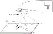
由于通过目测来将彩色分析仪的测量探头放置在待检测点的误差较大,为了解决这一问题,如图1所示,本发明实施例提供一种显示面板测试装置10,该显示面板测试装置10包括:Due to the large error of placing the measurement probe of the color analyzer at the point to be detected by visual inspection, in order to solve this problem, as shown in FIG. 1, an embodiment of the present invention provides a display
位置确定组件101和彩色分析仪102。
该彩色分析仪102包括主机1021和测量探头1022,测量探头1022用于获取显示面板出光面00的位置点的光学信息,该位置点为显示面板出光面00上测量探头1022所对准的点,主机1021用于根据光学信息确定该位置点的光学特征。The
位置确定组件101用于确定位置点在显示面板出光面00上的位置标识,该位置标识用于指示位置点在显示面板出光面00上的相对位置。The
在使用本发明实施例提供的显示面板测试装置10时,可以根据位置确定组件101确定的测量探头1022在初始位置点的位置标识以及预设的待检测点的位置标识来移动测量探头1022,使测量探头1022对准待检测点,并获取该待检测点的光学信息,再由主机1021通过该光学信息获取该待检测点的光学特征。When using the display
综上所述,本发明实施例提供的显示面板测试装置,能够通过位置确定组件确定测量探头所对准的位置点在显示面板出光面的位置标识,并根据该位置点的位置标识以及预设的待检测点的位置标识来将测量探头对准待检测点,再通过彩色分析仪获取待检测点的光学特征,无需通过目测将测量探头放置在待检测点,提高了确定的待检测点的精度。解决了相关技术中,通过目测来将彩色分析仪的测量探头放置在待检测点的误差较大的问题。达到了能够精确地确定待检测点在显示面板上的位置并分析其光学特征的效果。To sum up, the display panel testing device provided by the embodiment of the present invention can determine the position mark on the light-emitting surface of the display panel where the position point that the measuring probe is aimed at can be determined by the position determination component, and according to the position mark of the position point and the preset position mark. The position identification of the point to be detected can be used to align the measurement probe with the point to be detected, and then the optical characteristics of the point to be detected can be obtained through the color analyzer. precision. The problem in the related art that the measurement probe of the color analyzer is placed at the to-be-detected point by visual inspection is relatively large, and the problem is solved. The effect of being able to accurately determine the position of the point to be detected on the display panel and analyze its optical characteristics is achieved.
进一步的,请参考图2-1,其示出了本发明实施例提供的另一种显示面板测试装置的结构示意图,该显示面板测试装置在图1所示的显示面板测试装置的基础上增加了一些部件。Further, please refer to FIG. 2-1 , which shows a schematic structural diagram of another display panel testing apparatus provided by an embodiment of the present invention. The display panel testing apparatus is added on the basis of the display panel testing apparatus shown in FIG. 1 . some parts.
可选的,测量探头1022包括测量杆10221和探头10222,该探头10222设置在测量杆10221的一端并且该探头10222具有测试面d。测量探头10222所对准的点为位置点B(该位置点B可以为测试面d的中心所对准的点),该测试面d能够贴合在显示面板出光面00上的位置点B并获取该位置点B的光学信息。Optionally, the
位置确定组件101设置在该测量杆10221的标定点A,可选的,标定点A与位置点B所确定的直线与测试面d垂直,因而在测试面d贴合在显示面板出光面00上时,标定点A与位置点B所确定的直线也与显示面板出光面00垂直。The
可选的,主机1021和测量探头1022可以通过有线或无线的方式连接。Optionally, the
如图2-1所示,位置确定组件101可以通过一个旋转环103与测量杆10221转动连接,该旋转环103固定在测量杆10221上且能够以测量杆10221的轴线x为轴进行转动。此外,位置确定组件101还可以通过其他组件与测量杆10221转动连接,例如,在测量杆10221未设置有探头10222的一端可以设置有转轴,位置确定组件101可以通过该转轴与测量杆10221转动连接,本发明实施例不作出限制。As shown in FIG. 2-1 , the
根据位置确定组件的不同,本发明实施例提供的显示面板测试装置的具体结构可以有多种形式,本发明实施例以以下面三种为例进行说明。According to different position determining components, the specific structure of the display panel testing apparatus provided by the embodiment of the present invention may have various forms, and the embodiment of the present invention is described by taking the following three as examples.
第一种,如图2-2所示,该显示面板测试装置中的位置确定组件101包括处理组件1011和角度测量器1012。First, as shown in FIGS. 2-2 , the
该角度测量器1012设置在测量杆10221的标定点A,该标定点A和位置点B所确定的直线与显示面板出光面00垂直,该显示面板出光面00呈具有至少三个顶点的形状,例如图2-2所示,该显示面板出光面00为具有四个顶点的矩形。The
该角度测量器1012用于测量第一线段m与第二线段h所成的第一夹角a,The
该第一线段m为标定点A与显示面板出光面00的第一顶点P连成的线段,该第二线段h为标定点A与位置点B连成的线段,角度测量器1012还用于测量第三线段n与第二线段h所成的第二夹角b,第三线段n为标定点A与显示面板出光面00的第二顶点Q连成的线段,第一顶点P和第二顶点Q为显示面板出光面00任意两个相邻的顶点。其中,第二线段h的长度为已知量,可以由测试人员设置。The first line segment m is the line segment formed by the calibration point A and the first vertex P of the light-emitting
处理组件1011用于根据第一夹角a以及第二线段h的长度确定位置点B与第一顶点P之间的第一距离ρ1,根据第二夹角b以及第二线段h的长度确定位置点B与第二顶点Q之间的第二距离ρ2,第一距离ρ1和第二距离ρ2组成位置标识。第一距离ρ1和第二距离ρ2的确定方法可以参考本发明后续提供的方法实施例,在此不再赘述。The
图2-2中其他标记的含义可以参考图2-1,在此不再赘述。The meanings of other symbols in Figure 2-2 can be referred to in Figure 2-1, which will not be repeated here.
第二种,如图2-3所示,该显示面板测试装置的位置确定组件101包括处理组件1011和距离测量器1013。In the second type, as shown in FIGS. 2-3 , the
该距离测量器1013设置在测量杆10221的标定点A,该标定点A与位置点B所确定的直线与显示面板出光面00垂直。该显示面板出光面00呈具有至少三个顶点的形状,例如图2-3所示,该显示面板出光面00为具有四个顶点的矩形。The
该距离测量器1013用于测量标定点A与显示面板出光面00的顶点P之间的第一待测距离(即第一线段m的长度)以及测量标定点A与显示面板出光面00的顶点Q之间的第二待测距离(即第二线段h的长度)。The
处理组件1011用于根据标定点A与位置点B之间的第二线段h的长度以及第一待测距离确定位置点B与第一顶点P的第一距离ρ1,根据标定点A与位置点B之间的第二线段h的长度以及第二待测距离确定位置点B与第二顶点Q的第二距离ρ2,第一距离ρ1和第一距离ρ2组成位置标识。第一距离ρ1和第二距离ρ2的确定方法可以参考本发明后续提供的方法实施例,在此不再赘述。The
图2-3中其他标记的含义可以参考图2-1,在此不再赘述。The meanings of other symbols in Figure 2-3 can be referred to in Figure 2-1, and will not be repeated here.
第三种,如图2-4所示,该显示面板测试装置的位置确定组件101包括处理组件1011、距离测量器1013和角度测量器1012。The third type, as shown in FIGS. 2-4 , the
该距离测量器1013和该角度测量器1012设置在测量杆10221的标定点A,该标定点A和位置点B所确定的直线与显示面板出光面00垂直,该显示面板出光面00呈具有至少三个顶点的形状,例如图2-4所示,该显示面板出光面00为具有四个顶点的矩形。The
该距离测量器1013用于测量标定点A与显示面板出光面00的第一顶点P之间的第一待测距离以及测量标定点A与显示面板出光面00的第二顶点Q之间的第二待测距离。The
该角度测量器1012用于测量第一线段m与第二线段h所成的第一夹角a,该第一线段m为标定点A与显示面板出光面的第一顶点P连成的线段,该第二线段h为标定点A与位置点B连成的线段,角度测量器1012还用于测量第三线段n与第二线段h所成的第二夹角b,第三线段n为A标定点与显示面板出光面的第二顶点Q连成的线段,第一顶点P和第二顶点Q为显示面板出光面00任意两个相邻的顶点。The
该处理组件1011用于根据第二线段h的长度、第一待测距离以及第一夹角a确定标定点A与第一顶点P之间的第一距离ρ1,根据第二线段h的长度、第二待测距离以及第二夹角b确定标定点B与第二顶点Q之间的第二距离ρ2,该第一距离ρ1和该第二距离ρ2为位置标识,其中,第二线段h的长度为已知量,可以由测试人员设置。第一距离ρ1和第二距离ρ2的确定方法可以参考本发明后续提供的方法实施例,在此不再赘述。The
可选的,处理组件1011还用于根据第一夹角a、第一待测距离以及第二线段h的长度确定显示面板出光面00是否平整,第一待测距离为标定点A与第一顶点P的距离;和/或,处理组件1011用于根据第二夹角b、第二待测距离以及第二线段h的长度确定显示面板出光面00是否平整,第二待测距离为标定点A与第二顶点Q的距离。Optionally, the
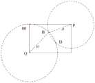
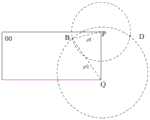
根据位置标识ρ1和ρ2可以在显示面板出光面00唯一确定一个点,上述三个显示面板测试装置获取的位置标识由显示面板出光面00上的点与两个顶点的距离唯一确定,也即是,位置标识所指示的点为两个以ρ1和ρ2的长度为半径的圆在显示面板出光面00中的交点。其中,如图2-5所示,当第一顶点P和第二顶点Q为显示面板出光面00上的对角线上的两个点时,以ρ1和ρ2的长度为半径的圆在显示面板出光面00中有两个交点(即图2-5中的B点和D点),因此位置标识不能够被唯一确定。所以,第一顶点P和第二顶点Q可以为显示面板出光面00上相邻的两个顶点,如图2-6所示,在第一顶点P和第二顶点Q为显示面板出光面00上相邻的两个顶点时,以ρ1和ρ2的长度为半径的圆在显示面板出光面00中有且仅有一个交点(即图2-6中的B点),另一个交点(即图2-6中的D点)不在显示面板出光面00上,因此可被忽略。According to the position marks ρ1 and ρ2 , a point can be uniquely determined on the light-emitting
可选的,距离测量器为红外测距传感器、激光测距传感器、超声波测距传感器和雷达测距传感器中的任意一种。例如,距离测量器为激光测距传感器,那么可以将激光测距传感器发出的激光对准显示面板出光面的顶点来测量距离测量器和该顶点之间的距离。Optionally, the distance measuring device is any one of an infrared ranging sensor, a laser ranging sensor, an ultrasonic ranging sensor and a radar ranging sensor. For example, if the distance measuring device is a laser distance measuring sensor, then the laser light emitted by the laser distance measuring sensor can be aimed at the vertex of the light-emitting surface of the display panel to measure the distance between the distance measuring device and the vertex.
综上所述,本发明实施例提供的显示面板测试装置,能够通过位置确定组件确定测量探头所对准的位置点在显示面板出光面的位置标识,并根据该位置点的位置标识以及预设的待检测点的位置标识来将测量探头对准待检测点,再通过彩色分析仪获取待检测点的光学特征,无需通过目测将测量探头放置在待检测点,提高了确定的待检测点的精度。解决了相关技术中,通过目测来将彩色分析仪的测量探头放置在待检测点的误差较大的问题。达到了能够精确地确定待检测点在显示面板上的位置并分析其光学特征的效果。To sum up, the display panel testing device provided by the embodiment of the present invention can determine the position mark on the light-emitting surface of the display panel where the position point that the measuring probe is aimed at can be determined by the position determination component, and according to the position mark of the position point and the preset position mark. The position identification of the point to be detected can be used to align the measurement probe with the point to be detected, and then the optical characteristics of the point to be detected can be obtained through the color analyzer. precision. The problem in the related art that the measurement probe of the color analyzer is placed at the to-be-detected point by visual inspection is relatively large, and the problem is solved. The effect of being able to accurately determine the position of the point to be detected on the display panel and analyze its optical characteristics is achieved.
图3是根据一示例性实施例示出的一种显示面板测试方法的流程图,该方法可以用于图1、图2-1、图2-2、图2-3、图2-4或图2-5所提供的显示面板测试装置,该显示面板测试装置包括位置确定组件和彩色分析仪,该彩色分析仪包括主机和测量探头,该方法包括:FIG. 3 is a flowchart illustrating a method for testing a display panel according to an exemplary embodiment, and the method can be used in FIG. 1 , FIG. 2-1 , FIG. 2-2 , FIG. 2-3 , FIG. 2-4 or FIG. 2-5 The display panel test device provided, the display panel test device includes a position determination component and a color analyzer, the color analyzer includes a host and a measurement probe, and the method includes:
步骤301、通过位置确定组件确定测量探头在显示面板出光面所对准的初始位置点的位置标识。Step 301: Determine the position identifier of the initial position point at which the measuring probe is aligned on the light-emitting surface of the display panel by the position determining component.
步骤302、根据初始位置点的位置标识以及预设的待检测点的位置标识将测量探头移动至待检测点。
步骤303、在待检测点进行测试。
综上所述,本发明实施例提供的显示面板测试装置,能够通过位置确定组件确定测量探头所对准的位置点在显示面板出光面的位置标识,并根据该位置点的位置标识以及预设的待检测点的位置标识来将测量探头对准待检测点,再通过彩色分析仪获取待检测点的光学特征,无需通过目测将测量探头放置在待检测点,提高了确定的待检测点的精度。解决了相关技术中,通过目测来将彩色分析仪的测量探头放置在待检测点的误差较大的问题。达到了能够精确地确定待检测点在显示面板上的位置并分析其光学特征的效果。To sum up, the display panel testing device provided by the embodiment of the present invention can determine the position mark on the light-emitting surface of the display panel where the position point that the measuring probe is aimed at can be determined by the position determination component, and according to the position mark of the position point and the preset position mark. The position identification of the point to be detected can be used to align the measurement probe with the point to be detected, and then the optical characteristics of the point to be detected can be obtained through the color analyzer. precision. The problem in the related art that the measurement probe of the color analyzer is placed at the to-be-detected point by visual inspection is relatively large, and the problem is solved. The effect of being able to accurately determine the position of the point to be detected on the display panel and analyze its optical characteristics is achieved.
图4是根据一示例性实施例示出的另一种显示面板测试方法的流程图,用于上述图2-2所示的显示面板测试装置,该显示面板测试方法可以包括下面几个步骤:FIG. 4 is a flowchart showing another display panel testing method according to an exemplary embodiment, which is used in the display panel testing apparatus shown in FIG. 2-2 above. The display panel testing method may include the following steps:
步骤401、将该显示面板测试装置中的测量探头移动到初始位置点。
如图2-2所示,在将测量探头10222移动到初始位置点后,测试面d与显示面板出光面00贴合。As shown in Fig. 2-2, after the
初始位置点可以是显示面板出光面上任意一个点,也可以是操作人员根据经验将测量探头放置在显示面板出光面上后,测量探头所对准的点,该初始位置点可以不是一个固定的点,每次进行光学特征的测试时,该初始位置点的位置可以不同。The initial position point can be any point on the light-emitting surface of the display panel, or it can be the point at which the measuring probe is aligned after the operator places the measuring probe on the light-emitting surface of the display panel according to experience. The initial position point may not be a fixed point. The position of the initial position point can be different each time the optical feature is tested.
步骤402、通过角度测量器测量第一线段与第二线段所成的第一夹角。
如图2-2所示,第一线段为标定点A与显示面板出光面00的第一顶点P连成的线段m,第二线段为标定点A与位置点B连成的线段h。可以通过角度测量器1012测量第一线段m与第二线段h所成的第一夹角a。As shown in Figure 2-2, the first line segment is the line segment m connecting the calibration point A and the first vertex P of the light-emitting
步骤403、通过角度测量器测量第三线段与第二线段所成的第二夹角。
如图2-2所示,第三线段n为标定点A与显示面板出光面00的第二顶点Q连成的线段。可以通过角度测量器1012测量第三线段n与第二线段h所成的第二夹角b。As shown in FIG. 2-2 , the third line segment n is a line segment formed by connecting the calibration point A and the second vertex Q of the light-emitting
其中,在步骤402和步骤403中,第一顶点P和第二顶点Q为显示面板出光面00上任意两个相邻的顶点。Wherein, in
此外,步骤403还可以在步骤402之前执行,或者,步骤403还可以与步骤402同时执行,本发明实施例不作出限制。In addition,
步骤404、通过处理组件确定第一距离和第二距离。Step 404: Determine the first distance and the second distance through the processing component.
如图2-2所示,可以通过处理组件1011根据第一夹角a以及第二线段h的长度确定位置点B与第一顶点P之间的第一距离ρ1,根据第二夹角b以及第二线段h的长度确定位置点B与第二顶点Q之间的第二距离ρ2。该第一距离ρ1和该第二距离ρ2可以组成位置标识。根据该位置标识能够在显示面板出光面唯一确定一个点,确定方法可以参考图2-5,在此不再赘述。As shown in FIG. 2-2 , the
可选的,由于标定点A与位置点B所连成的线段测试面d垂直,因而当测试面d贴合在显示面板出光面00上时,标定点A与位置点B所连成的线段与显示面板出光面00垂直。此时,标定点A、位置点B和第一顶点P构成直角三角形,标定点A、位置点B和第二顶点Q也构成直角三角形,则处理组件可以根据公式:ρ1=h1tana以及公式:ρ2=h1tanb计算得到ρ1和ρ2的值,其中,h1为第二线段h的长度,且h1为已知量,可以由测试人员设置。Optionally, since the line segment test surface d formed by the calibration point A and the position point B is perpendicular, when the test surface d is attached to the light-emitting
步骤405、根据初始位置点的位置标识以及预设的待检测点的位置标识将测量探头移动至待检测点。
在确定了初始位置点的位置标识后,可以根据该初始位置点的位置标识与预设的待检测点的位置标识的相对位置来移动测量探头,并在移动的过程中通过位置确定组件确定测量探头在显示面板出光面所对准的位置点的位置标识,直至测量探头对准的位置点的位置标识为预设的待检测点的位置标识时停止移动测量探头。After the position identification of the initial position point is determined, the measuring probe can be moved according to the relative position between the position identification of the initial position point and the preset position identification of the point to be detected, and the measurement probe can be determined by the position determination component during the movement process. The probe displays the position identification of the position point aligned with the light-emitting surface of the panel, and stops moving the measurement probe until the position identification of the position point aligned with the measuring probe is the preset position identification of the point to be detected.
预设的待检测点的位置标识可以在测试之前确定,实际应用中可以设置一个或多个待检测点,本发明实施例不作出限制。The preset position identifiers of the points to be detected may be determined before the test. In practical applications, one or more points to be detected may be set, which is not limited in this embodiment of the present invention.
步骤406、在待检测点进行测试。
在将测量探头移动到预设的待检测点后,可以通过测量探头获取待检测点的图像信息,再通过主机分析该图像信息,以获取待检测点的光学特征。After the measuring probe is moved to the preset to-be-detected point, the image information of the to-be-detected point can be acquired by the measuring probe, and then the image information can be analyzed by the host to obtain the optical characteristics of the to-be-detected point.
测试人员可以通过步骤401至步骤406的方式测试同一型号的每一个显示面板出光面上的待检测点的光学特征,且能够保证测试的每个显示面板出光面上的待检测点的位置基本相同。The tester can test the optical characteristics of the points to be detected on the light-emitting surface of each display panel of the same model by means of
综上所述,本发明实施例提供的显示面板测试方法,能够通过位置确定组件确定测量探头所对准的位置点在显示面板出光面的位置标识,并根据该位置点的位置标识以及预设的待检测点的位置标识来将测量探头对准待检测点,再通过彩色分析仪获取待检测点的光学特征,无需通过目测将测量探头放置在待检测点,提高了确定的待检测点的精度。解决了相关技术中,通过目测来将彩色分析仪的测量探头放置在待检测点的误差较大的问题。达到了能够精确地确定待检测点在显示面板上的位置并分析其光学特征的效果。To sum up, the display panel testing method provided by the embodiment of the present invention can determine the position mark on the light-emitting surface of the display panel of the position point aligned by the measuring probe through the position determination component, and according to the position mark of the position point and the preset position mark. The position identification of the point to be detected can be used to align the measurement probe with the point to be detected, and then the optical characteristics of the point to be detected can be obtained through the color analyzer. precision. The problem in the related art that the measurement probe of the color analyzer is placed at the to-be-detected point by visual inspection is relatively large, and the problem is solved. The effect of being able to accurately determine the position of the point to be detected on the display panel and analyze its optical characteristics is achieved.
图5是根据一示例性实施例示出的另一种显示面板测试方法的流程图,用于上述图2-3所描述的装置,该显示面板测试方法可以包括下面几个步骤:FIG. 5 is a flow chart of another display panel testing method according to an exemplary embodiment, which is used in the apparatus described in FIGS. 2-3 above. The display panel testing method may include the following steps:
步骤501、将显示面板测试装置中的测量探头移动到初始位置点。
本步骤可以参考图4所示实施例中的步骤401,在此不再赘述。For this step, reference may be made to step 401 in the embodiment shown in FIG. 4 , and details are not repeated here.
步骤502、通过距离测量器测量标定点与显示面板出光面的第一顶点之间的第一待测距离。
如图2-3所示,第一待测距离为标定点A与第一顶点P连成的线段m的长度。As shown in Figure 2-3, the first distance to be measured is the length of the line segment m connecting the calibration point A and the first vertex P.
步骤503、通过距离测量器测量标定点与显示面板出光面的第二顶点之间的第二待测距离。
如图2-3所示,第二待测距离为标定点A与第二顶点Q连成的线段n的长度。As shown in Figure 2-3, the second distance to be measured is the length of the line segment n formed by the calibration point A and the second vertex Q.
步骤502和步骤503中,第一顶点P和第二顶点Q为显示面板出光面上任意两个相邻的顶点。In
此外,步骤503还可以在步骤502之前执行,或者,步骤503还可以与步骤502同时执行,本发明实施例不作出限制。In addition,
步骤504、通过处理组件确定第一距离和第二距离。Step 504: Determine the first distance and the second distance through the processing component.
如图2-3所示,可以通过处理组件1011根据第一待测距离以及第二线段h的长度确定位置点B与P第一顶点之间的第一距离ρ1,根据第二待测距离以及第二线段h的长度确定位置点B与第二顶点Q之间的第二距离ρ2。该第一距离ρ1和第二距离ρ2可以组成位置标识。根据该位置标识能够在显示面板出光面唯一确定一个点,确定方法可以参考图2-5,在此不再赘述。As shown in FIG. 2-3 , the
可选的,由于标定点A与位置点B所连成的线段测试面d垂直,因而当测试面d贴合在显示面板出光面00上时,标定点A与位置点B所连成的线段与显示面板出光面00垂直。此时,标定点A、位置点B和第一顶点P构成直角三角形,标定点A、位置点B和第二顶点Q也构成直角三角形,则处理组件根据公式:

步骤505、根据初始位置点的位置标识以及预设的待检测点的位置标识将测量探头移动至待检测点。
本步骤可以参考图4所示的实施例中的步骤405,在此不再赘述。For this step, reference may be made to step 405 in the embodiment shown in FIG. 4 , and details are not repeated here.
步骤506、在待检测点进行测试。
在将测量探头移动到预设的待检测点后,可以通过测量探头获取待检测点的图像信息,再通过主机分析该图像信息,以获取待检测点的光学特征。After the measuring probe is moved to the preset to-be-detected point, the image information of the to-be-detected point can be acquired by the measuring probe, and then the image information can be analyzed by the host to obtain the optical characteristics of the to-be-detected point.
测试人员可以通过步骤501至步骤506的方式测试同一型号的每一个显示面板出光面上的待检测点的光学特征,且能够保证测试的每个显示面板出光面上的待检测点的位置基本相同。The tester can test the optical characteristics of the points to be detected on the light-emitting surface of each display panel of the same model by means of
综上所述,本发明实施例提供的显示面板测试方法,能够通过位置确定组件确定测量探头所对准的位置点在显示面板出光面的位置标识,并根据该位置点的位置标识以及预设的待检测点的位置标识来将测量探头对准待检测点,再通过彩色分析仪获取待检测点的光学特征,无需通过目测将测量探头放置在待检测点,提高了确定的待检测点的精度。解决了相关技术中,通过目测来将彩色分析仪的测量探头放置在待检测点的误差较大的问题。达到了能够精确地确定待检测点在显示面板上的位置并分析其光学特征的效果。To sum up, the display panel testing method provided by the embodiment of the present invention can determine the position mark on the light-emitting surface of the display panel of the position point aligned by the measuring probe through the position determination component, and according to the position mark of the position point and the preset position mark. The position identification of the point to be detected can be used to align the measurement probe with the point to be detected, and then the optical characteristics of the point to be detected can be obtained through the color analyzer. precision. The problem in the related art that the measurement probe of the color analyzer is placed at the to-be-detected point by visual inspection is relatively large, and the problem is solved. The effect of being able to accurately determine the position of the point to be detected on the display panel and analyze its optical characteristics is achieved.
图6是根据一示例性实施例示出的另一种显示面板测试方法的流程图,用于上述图2-4所描述的装置,该显示面板测试方法可以包括下面几个步骤:FIG. 6 is a flow chart of another display panel testing method according to an exemplary embodiment, which is used in the apparatus described in FIGS. 2-4 above. The display panel testing method may include the following steps:
步骤601、通过处理组件确定显示面板出光面是否平整。Step 601: Determine whether the light-emitting surface of the display panel is flat by the processing component.
在显示面板出光面平整时,执行步骤602;在显示面板出光面不平整时,执行步骤603。When the light-emitting surface of the display panel is flat,
处理组件根据第一夹角a、第一待测距离以及第二线段h的长度确定显示面板出光面是否平整,和/或,处理组件根据第二夹角b、第二待测距离以及第二线段h的长度确定显示面板出光面是否平整,其中,第一待测距离为标定点A与第一顶点P连成的线段m的长度,第二待测距离为标定点A与第二顶点Q连成的线段n的长度。The processing component determines whether the light-emitting surface of the display panel is flat according to the first included angle a, the first distance to be measured, and the length of the second line segment h, and/or the processing component determines whether the light-emitting surface of the display panel is flat according to the second included angle b, the second distance to be measured, and the second The length of the line segment h determines whether the light-emitting surface of the display panel is flat, wherein the first distance to be measured is the length of the line segment m formed by the calibration point A and the first vertex P, and the second distance to be measured is the calibration point A and the second vertex Q. The length of the connected line segment n.
处理组件可以在cosa等于h1/m1,和/或,cosb等于h1/n1时,确定显示面板出光面平整,并在其他情况时确定显示面板出光面不平整。其中,h1为第二线段h的长度,m1为第一待测距离,n1为第二待测距离。The processing component may determine that the light-emitting surface of the display panel is flat when cosa is equal to h1 /m1 , and/or cosb is equal to h1 /n1 , and determine that the light-emitting surface of the display panel is uneven in other cases. Wherein, h1 is the length of the second line segment h, m1 is the first distance to be measured, and n1 is the second distance to be measured.
此外,cosa和h1/m1之间的差值小于预设的第一阈值时,可以认为cosa和h1/m1相等,cosb和h1/n1之间的差值小于预设的第二阈值时,可以认为cosb和h1/n1相等,第一阈值和第二阈值可以是具体的值,也可以是百分比(该百分比可以为cosa、cosb、h1/m1或h1/n1等的百分比),且第一阈值和第二阈值可以相等也可以不相等,第一阈值和第二阈值可以根据显示面板常规的平整程度设置。In addition, when the difference between cosa and h1 /m1 is smaller than the preset first threshold, it can be considered that cosa and h1 /m1 are equal, and the difference between cosb and h1 /n1 is smaller than the preset first threshold When the second threshold is used, cosb and h1 /n1 can be considered equal, and the first threshold and the second threshold can be specific values or percentages (the percentages can be cosa, cosb, h1 /m1 or h1 /n1 , etc.), and the first threshold and the second threshold may or may not be equal, and the first threshold and the second threshold may be set according to the conventional flatness of the display panel.
步骤602、通过角度测量器或距离测量器确定测量探头在显示面板出光面所对准的初始位置点的位置标识。执行步骤607。Step 602: Determine the position identifier of the initial position point at which the measuring probe is aligned on the light-emitting surface of the display panel by using an angle measurer or a distance measurer. Step 607 is executed.
在显示面板出光面平整时,可以参考上述图4所示实施例中的步骤401至步骤404,通过角度测量器确定测量探头在显示面板出光面所对准的初始位置点的位置标识,或者可以参考上述图5所示实施例中的步骤501至步骤504,通过距离测量器确定测量探头在显示面板出光面所对准的初始位置点的位置标识,在此不做赘述。When the light-emitting surface of the display panel is flat, you can refer to
步骤603、通过距离测量器分别获取标定点到第一顶点的第一待测距离,以及标定点到第二顶点的第二待测距离。执行步骤604。Step 603: Obtain a first distance to be measured from the calibration point to the first vertex, and a second distance to be measured from the calibration point to the second vertex, respectively, through a distance measurer. Step 604 is performed.
在显示面板不平整时,如图2-4所示,可以通过距离测量器1013分别获取标定点A到第一顶点P的第一待测距离,以及标定点A到第二顶点Q的第二待测距离。When the display panel is not flat, as shown in Figures 2-4, the
步骤604、通过角度测量器获取第一线段与第二线段所成的第一夹角,以及第三线段与第二线段所成的第二夹角。执行步骤605。
如图2-4所示,可以通过角度测量器1012获取第一线段m与第二线段h所成的第一夹角a,以及第三线段n与第二线段h所成的第二夹角b。As shown in FIG. 2-4 , the first angle a formed by the first line segment m and the second line segment h, and the second angle formed by the third line segment n and the second line segment h can be obtained through the
此外,步骤604还可以在步骤603之前执行,或者,步骤604还可以与步骤603同时执行,本发明实施例不作出限制。In addition,
步骤605、通过处理组件根据第一预设公式确定标定点与第一顶点之间的第一距离。执行步骤606。Step 605: Determine the first distance between the calibration point and the first vertex by the processing component according to the first preset formula. Step 606 is performed.
第一预设公式为
步骤606、通过处理组件根据第二预设公式确定标定点与第二顶点之间的第二距离。执行步骤607。Step 606: Determine the second distance between the calibration point and the second vertex by the processing component according to the second preset formula. Step 607 is executed.
第二预设公式为
通过步骤605和步骤606能够确定ρ1和ρ2,ρ1和ρ2可以组成初始位置点的位置标识。根据该位置标识能够在显示面板出光面唯一确定一个点,确定方法可以参考图2-5,在此不再赘述。其中,第二线段h的长度h1为已知量,可以由测试人员设置。ρ1 and ρ2 can be determined through
另外,步骤606还可以在步骤605之前执行,或者步骤606还可以与步骤605同时执行,本发明实施例不作出限制。In addition,
需要说明的是,在显示面板平整时,同样可以采用步骤603至步骤606的方法来确定初始位置点的位置标识。It should be noted that, when the display panel is flat, the methods of
步骤607、根据初始位置点的位置标识以及预设的待检测点的位置标识将测量探头移动至待检测点。执行步骤608。
本步骤可以参考图4所示实施例中的步骤405,在此不再赘述。For this step, reference may be made to step 405 in the embodiment shown in FIG. 4 , and details are not repeated here.
步骤608、在待检测点进行测试。
在将测量探头移动到预设的待检测点后,可以通过测量探头获取待检测点的图像信息,再通过主机分析该图像信息,以获取待检测点的光学特征。After the measuring probe is moved to the preset to-be-detected point, the image information of the to-be-detected point can be acquired by the measuring probe, and then the image information can be analyzed by the host to obtain the optical characteristics of the to-be-detected point.
测试人员可以通过步骤601至步骤608的方式测试同一型号的每一个显示面板出光面上的待检测点的光学特征,且能够保证测试的每个显示面板出光面上的待检测点的位置基本相同。The tester can test the optical characteristics of the points to be detected on the light-emitting surface of each display panel of the same model by means of
综上所述,本发明实施例提供的显示面板测试装置,能够通过位置确定组件确定测量探头所对准的位置点在显示面板出光面的位置标识,并根据该位置点的位置标识以及预设的待检测点的位置标识来将测量探头对准待检测点,再通过彩色分析仪获取待检测点的光学特征,无需通过目测将测量探头放置在待检测点,提高了确定的待检测点的精度。解决了相关技术中,通过目测来将彩色分析仪的测量探头放置在待检测点的误差较大的问题。达到了能够精确地确定待检测点在显示面板上的位置并分析其光学特征的效果。To sum up, the display panel testing device provided by the embodiment of the present invention can determine the position mark on the light-emitting surface of the display panel where the position point that the measuring probe is aimed at can be determined by the position determination component, and according to the position mark of the position point and the preset position mark. The position identification of the point to be detected can be used to align the measurement probe with the point to be detected, and then the optical characteristics of the point to be detected can be obtained through the color analyzer. precision. The problem in the related art that the measurement probe of the color analyzer is placed at the to-be-detected point by visual inspection is relatively large, and the problem is solved. The effect of being able to accurately determine the position of the point to be detected on the display panel and analyze its optical characteristics is achieved.
本发明实施例中术语“和/或”,仅仅是一种描述关联对象的关联关系,表示可以存在三种关系,例如,A和/或B,可以表示:单独存在A,同时存在A和B,单独存在B这三种情况。另外,本文中字符“/”,一般表示前后关联对象是一种“或”的关系。The term "and/or" in this embodiment of the present invention is only an association relationship for describing associated objects, indicating that three relationships may exist, for example, A and/or B may indicate that A exists alone, and A and B exist simultaneously , there are three cases of B alone. In addition, the character "/" in this document generally indicates that the related objects are an "or" relationship.
上述所有可选技术方案,可以采用任意结合形成本发明的可选实施例,在此不再一一赘述。All the above-mentioned optional technical solutions can be combined arbitrarily to form optional embodiments of the present invention, which will not be repeated here.
需要说明的是:上述实施例提供的显示面板测试装置在测试显示面板的光学特性时,仅以上述各功能组件的划分进行举例说明,实际应用中,可以根据需要而将上述功能分配由不同的功能组件完成,即将装置的内部结构划分成不同的功能组件,以完成以上描述的全部或者部分功能。另外,上述实施例提供的显示面板测试装置和显示面板测试方法实施例属于同一构思,其具体实现过程详见方法实施例,这里不再赘述。It should be noted that when the display panel testing device provided in the above embodiment tests the optical characteristics of the display panel, only the division of the above functional components is used as an example for illustration. In practical applications, the above functions can be allocated by different Completion of functional components means dividing the internal structure of the device into different functional components to complete all or part of the functions described above. In addition, the embodiments of the display panel testing apparatus and the display panel testing method provided by the above embodiments belong to the same concept, and the specific implementation process thereof is detailed in the method embodiments, which will not be repeated here.
以上所述仅为本发明的较佳实施例,并不用以限制本发明,凡在本发明的精神和原则之内,所作的任何修改、等同替换、改进等,均应包含在本发明的保护范围之内。The above are only preferred embodiments of the present invention and are not intended to limit the present invention. Any modifications, equivalent replacements, improvements, etc. made within the spirit and principles of the present invention shall be included in the protection of the present invention. within the range.
Claims (12)
Translated fromChinese

Priority Applications (2)
| Application Number | Priority Date | Filing Date | Title |
|---|---|---|---|
| CN201710591713.3ACN107389316B (en) | 2017-07-19 | 2017-07-19 | Display panel testing device and display panel testing method |
| US15/960,887US10551250B2 (en) | 2017-07-19 | 2018-04-24 | Device and method for testing display panel |
Applications Claiming Priority (1)
| Application Number | Priority Date | Filing Date | Title |
|---|---|---|---|
| CN201710591713.3ACN107389316B (en) | 2017-07-19 | 2017-07-19 | Display panel testing device and display panel testing method |
Publications (2)
| Publication Number | Publication Date |
|---|---|
| CN107389316A CN107389316A (en) | 2017-11-24 |
| CN107389316Btrue CN107389316B (en) | 2020-11-10 |
Family
ID=60335800
Family Applications (1)
| Application Number | Title | Priority Date | Filing Date |
|---|---|---|---|
| CN201710591713.3AExpired - Fee RelatedCN107389316B (en) | 2017-07-19 | 2017-07-19 | Display panel testing device and display panel testing method |
Country Status (2)
| Country | Link |
|---|---|
| US (1) | US10551250B2 (en) |
| CN (1) | CN107389316B (en) |
Families Citing this family (5)
| Publication number | Priority date | Publication date | Assignee | Title |
|---|---|---|---|---|
| CN109238151B (en)* | 2018-06-29 | 2020-06-05 | 苏州富强科技有限公司 | Detection device positioning method |
| CN109286815A (en)* | 2018-11-30 | 2019-01-29 | 福建捷联电子有限公司 | A kind of positioning of display equipment picture center and automatic testing method |
| CN110879135B (en)* | 2019-11-29 | 2021-08-10 | 昆山国显光电有限公司 | Optical testing device and optical testing method |
| CN111912609B (en)* | 2020-08-11 | 2022-08-26 | 京东方科技集团股份有限公司 | Measuring device and measuring method |
| CN114414973A (en)* | 2021-12-22 | 2022-04-29 | 南京泊纳莱电子科技有限公司 | A kind of electronic device detection method, device and electronic equipment |
Citations (7)
| Publication number | Priority date | Publication date | Assignee | Title |
|---|---|---|---|---|
| CN101118719A (en)* | 2007-08-29 | 2008-02-06 | 浙江大学 | Gantry-type four-dimensional automatic measuring platform for testing the light and color performance of display screens |
| CN101324481A (en)* | 2008-07-30 | 2008-12-17 | 京东方科技集团股份有限公司 | Optical property detection method and system, optical property detection control equipment |
| CN101398999A (en)* | 2007-09-28 | 2009-04-01 | 鹏智科技(深圳)有限公司 | Display equipment test device and method |
| CN101806963A (en)* | 2009-02-17 | 2010-08-18 | 日本麦可罗尼克斯股份有限公司 | Method and device for inspecting liquid crystal display panel |
| TW201201079A (en)* | 2010-06-23 | 2012-01-01 | Pixart Imaging Inc | Optical touch monitor |
| CN104677314A (en)* | 2015-03-02 | 2015-06-03 | 合肥京东方光电科技有限公司 | Device and method for detecting surface flatness of display panel |
| US9223441B1 (en)* | 2014-08-07 | 2015-12-29 | Microsoft Technology Licensing, Llc | Detection surface for a computing device |
Family Cites Families (14)
| Publication number | Priority date | Publication date | Assignee | Title |
|---|---|---|---|---|
| GB2344649B (en)* | 1998-12-09 | 2001-01-03 | Acer Technologies Sdn Bhd | Color testing system for testing color output of a display device |
| JP3314747B2 (en)* | 1999-01-29 | 2002-08-12 | ミノルタ株式会社 | LCD panel optical measuring device |
| TW200828210A (en)* | 2006-12-18 | 2008-07-01 | Wistron Corp | Method and device of rapidly building a gray-level and brightness curve of displayer |
| TWI408354B (en)* | 2009-07-24 | 2013-09-11 | Wistron Corp | Apparatus for assisting inspection of a display, a display inspecting module, and a display inspecting method |
| CN101710486B (en)* | 2009-11-15 | 2012-03-14 | 苏州佳世达电通有限公司 | Automatic alignment system and method thereof, and test system of display device and method thereof |
| KR101831400B1 (en)* | 2011-06-16 | 2018-02-26 | 삼성전자주식회사 | Display apparatus and calibration method thereof |
| EP2698602A1 (en)* | 2012-08-16 | 2014-02-19 | Leica Geosystems AG | Hand-held distance measuring device with angle calculation unit |
| TWI512277B (en)* | 2013-01-04 | 2015-12-11 | Taiwan Power Testing Technology Co Ltd | Monitor inspection equipment |
| US8993953B2 (en)* | 2013-01-09 | 2015-03-31 | Shenzhen China Star Optoelectronics Technology Co., Ltd | Apparatus and system for measuring flicker of display panel |
| CN104006949A (en)* | 2013-02-26 | 2014-08-27 | 北京京东方光电科技有限公司 | Transmittance detection device |
| TWI498580B (en)* | 2013-11-29 | 2015-09-01 | Wistron Corp | Length measuring method and length measuring apparatus |
| TWI566579B (en)* | 2015-12-04 | 2017-01-11 | 瑞軒科技股份有限公司 | Detecting device for display and detecting method thereof |
| US9989415B1 (en)* | 2017-01-23 | 2018-06-05 | IEI Intergration Corp. | Method for creating uniformity compensation look-up table |
| CN106969707B (en)* | 2017-04-07 | 2019-06-28 | 京东方科技集团股份有限公司 | A kind of detection device and its control method |
- 2017
- 2017-07-19CNCN201710591713.3Apatent/CN107389316B/ennot_activeExpired - Fee Related
- 2018
- 2018-04-24USUS15/960,887patent/US10551250B2/ennot_activeExpired - Fee Related
Patent Citations (7)
| Publication number | Priority date | Publication date | Assignee | Title |
|---|---|---|---|---|
| CN101118719A (en)* | 2007-08-29 | 2008-02-06 | 浙江大学 | Gantry-type four-dimensional automatic measuring platform for testing the light and color performance of display screens |
| CN101398999A (en)* | 2007-09-28 | 2009-04-01 | 鹏智科技(深圳)有限公司 | Display equipment test device and method |
| CN101324481A (en)* | 2008-07-30 | 2008-12-17 | 京东方科技集团股份有限公司 | Optical property detection method and system, optical property detection control equipment |
| CN101806963A (en)* | 2009-02-17 | 2010-08-18 | 日本麦可罗尼克斯股份有限公司 | Method and device for inspecting liquid crystal display panel |
| TW201201079A (en)* | 2010-06-23 | 2012-01-01 | Pixart Imaging Inc | Optical touch monitor |
| US9223441B1 (en)* | 2014-08-07 | 2015-12-29 | Microsoft Technology Licensing, Llc | Detection surface for a computing device |
| CN104677314A (en)* | 2015-03-02 | 2015-06-03 | 合肥京东方光电科技有限公司 | Device and method for detecting surface flatness of display panel |
Also Published As
| Publication number | Publication date |
|---|---|
| US20190025126A1 (en) | 2019-01-24 |
| US10551250B2 (en) | 2020-02-04 |
| CN107389316A (en) | 2017-11-24 |
Similar Documents
| Publication | Publication Date | Title |
|---|---|---|
| CN107389316B (en) | Display panel testing device and display panel testing method | |
| CN103438824B (en) | A kind of large-scale wallboard class Components Digital quality determining method | |
| CN102183524B (en) | Double-CCD (Charge Coupled Device) detecting method and system for apparent defect assessment of civil engineering structure | |
| CN104568781A (en) | Method for automatically detecting and evaluating color of laser beam emitting paper and quality of laser beams | |
| CN104422406A (en) | Planeness measurement system and method | |
| CN107388995B (en) | Handheld plane straightness detection device and plane straightness detection method | |
| TWI636234B (en) | Shape measuring method, shape measuring device and deformation detecting device | |
| Dury et al. | Characterising 3D optical scanner measurement performance for precision engineering | |
| CN103758017A (en) | Detection method and detection system for three-dimensional pavement elevation grid numerical value | |
| KR101032788B1 (en) | Egg freshness checking device | |
| CN117109481A (en) | Method for detecting and evaluating overall flatness and overcurrent capacity of concrete with overcurrent surface | |
| CN104391390B (en) | Substrate checking device and method | |
| CN106940175A (en) | Sphere ring gauge and gauge head lengthy calibration method for endoporus parameter measuring apparatus gauge head lengthy calibration | |
| CN107392899B (en) | An automatic detection method for the horizontal angle of the wear scar of a steel ball wear scar image | |
| CN114136972A (en) | Blue light scanning part integrated detection tool and part quality evaluation method | |
| CN108253912B (en) | Method for checking interrelation of measuring pins of three-coordinate measuring machine | |
| CN108663376A (en) | A kind of seamless steel pipe quality detection device and detection method | |
| CN204373781U (en) | A kind of light beam laser paper color and light beam quality automatic checkout system | |
| Zhu et al. | Image quality evaluation method for surface crack detection based on standard test chart | |
| CN207456361U (en) | A kind of quick detection angles cubing | |
| CN110567345A (en) | Non-contact type pipe wall thickness measuring method and system based on machine vision | |
| CN115451816A (en) | Three-dimensional scanning-based detection method for size of complex casting mold | |
| CN106969707A (en) | A kind of detection means and its control method | |
| CN114777607A (en) | Device and method for detecting coaxiality error of a rotating body | |
| CN115420762A (en) | Method for evaluating capability of detecting internal micro defects of metal parts by industrial CT |
Legal Events
| Date | Code | Title | Description |
|---|---|---|---|
| PB01 | Publication | ||
| PB01 | Publication | ||
| SE01 | Entry into force of request for substantive examination | ||
| SE01 | Entry into force of request for substantive examination | ||
| GR01 | Patent grant | ||
| GR01 | Patent grant | ||
| CF01 | Termination of patent right due to non-payment of annual fee | Granted publication date:20201110 | |
| CF01 | Termination of patent right due to non-payment of annual fee |