CN107342321B - SOI LIGBT with controllable collector electrode slot - Google Patents
SOI LIGBT with controllable collector electrode slotDownload PDFInfo
- Publication number
- CN107342321B CN107342321BCN201710768209.6ACN201710768209ACN107342321BCN 107342321 BCN107342321 BCN 107342321BCN 201710768209 ACN201710768209 ACN 201710768209ACN 107342321 BCN107342321 BCN 107342321B
- Authority
- CN
- China
- Prior art keywords
- collector
- region
- groove
- gate
- dielectric layer
- Prior art date
- Legal status (The legal status is an assumption and is not a legal conclusion. Google has not performed a legal analysis and makes no representation as to the accuracy of the status listed.)
- Active
Links
Images


Classifications
- H—ELECTRICITY
- H10—SEMICONDUCTOR DEVICES; ELECTRIC SOLID-STATE DEVICES NOT OTHERWISE PROVIDED FOR
- H10D—INORGANIC ELECTRIC SEMICONDUCTOR DEVICES
- H10D12/00—Bipolar devices controlled by the field effect, e.g. insulated-gate bipolar transistors [IGBT]
- H10D12/411—Insulated-gate bipolar transistors [IGBT]
- H10D12/421—Insulated-gate bipolar transistors [IGBT] on insulating layers or insulating substrates, e.g. thin-film IGBTs
- H—ELECTRICITY
- H10—SEMICONDUCTOR DEVICES; ELECTRIC SOLID-STATE DEVICES NOT OTHERWISE PROVIDED FOR
- H10D—INORGANIC ELECTRIC SEMICONDUCTOR DEVICES
- H10D62/00—Semiconductor bodies, or regions thereof, of devices having potential barriers
- H10D62/10—Shapes, relative sizes or dispositions of the regions of the semiconductor bodies; Shapes of the semiconductor bodies
- H10D62/13—Semiconductor regions connected to electrodes carrying current to be rectified, amplified or switched, e.g. source or drain regions
- H10D62/137—Collector regions of BJTs
Landscapes
- Thin Film Transistor (AREA)
Abstract
Translated fromChinese
Description
Translated fromChinese技术领域technical field
本发明属于功率半导体技术领域,涉及一种具有可控集电极槽的SOI LIGBT(Lateral Insulated Gate Bipolar Transistor,横向绝缘栅双极型晶体管)。The invention belongs to the technical field of power semiconductors, and relates to a SOI LIGBT (Lateral Insulated Gate Bipolar Transistor, lateral insulated gate bipolar transistor) with a controllable collector groove.
背景技术Background technique
绝缘栅双极型晶体管(IGBT)是一种MOSFET场效应和双极型晶体管(Bipolarjunction transistor,BJT)等效复合的新型电力电子器件。它兼具了MOSFET输入阻抗高和驱动简单的优点,以及BJT器件电流密度高和低导通压降的优势,已成为现代电力电子电路应用中的核心电子元器件之一。因其在高压大电流领域内独特的优势,IGBT器件广泛应用于交通运输、智能电网、家用电器、工业、医学、航空航天等众多领域。Insulated gate bipolar transistor (IGBT) is a new type of power electronic device that is equivalently combined with MOSFET field effect and bipolar junction transistor (BJT). It has both the advantages of high input impedance and simple driving of MOSFET, as well as the advantages of high current density and low conduction voltage drop of BJT devices, and has become one of the core electronic components in modern power electronic circuit applications. Because of its unique advantages in the field of high voltage and high current, IGBT devices are widely used in transportation, smart grid, household appliances, industry, medicine, aerospace and many other fields.
LIGBT由于可以与COMS工艺良好兼容,且SOI技术具有泄漏电流小,便于隔离等优势,因此,SOI LIGBT是单片功率集成芯片的核心元器件。导通状态下,LIGBT器件漂移区内存在电导调制效应,因此漂移区内储存有高浓度的电子空穴对;器件关断过程中,空穴可以通过发射极端的体接触区流出,而电子在集电极端没有泄放通道,电子消失主要靠与空穴的复合,这使器件拖尾电流变长、关断速度变慢和关断损耗变大。Because LIGBT is well compatible with COMS technology, and SOI technology has the advantages of small leakage current and easy isolation, SOI LIGBT is the core component of monolithic power integrated chips. In the on state, there is a conductance modulation effect in the drift region of the LIGBT device, so there is a high concentration of electron-hole pairs stored in the drift region; during the device off process, the holes can flow out through the body contact region of the emitter terminal, and the electrons in the drift region There is no discharge channel at the collector terminal, and the disappearance of electrons mainly depends on the recombination with holes, which makes the tail current of the device longer, the turn-off speed slower and the turn-off loss larger.
为了解决LIGBT长拖尾电流问题,研究者们提出了短路阳极LIGBT(SA-LIGBT,Shorted Anode LIGBT),即在器件阳极端的P+集电区附近增加一个N+集电区,这样电子就可以通过N+集电区高速抽取出,器件关断速度被大大的加快。但是SA-LIGBT带来的一个严重的问题就是Snapback效应。一般的解决办法都是通过增大MOS模式下电子电流路径上P+集电区与N+集电区之间的电阻来克服Snapback效应。文献Juti-Hoon Chum,Dae-SeokByeon,Jae-Keun Oh.,Min-Koo Han and Ysaln-lk Choi,【A Fast-Switching SOI SA-LIGBT without NDR region】提出的SSA-LIGBT就是利用P+集电区和N+集电区中间高电阻率漂移区来产生足够高的压降,使P+集电区/N缓冲区二极管在较低的电压下就发生电导调制效应,有效抑制Snapback效应。但SSA-LIGBT结构中P+集电区和N+集电区之间需要足够长的漂移区才能有效消除Snapback效应,这极大的增加芯片面积和限制器件的电流密度,如图1所示。文献Long Zhang,Jing Zhu,Weifeng Sun,Yicheng Du,Hui Yu,,Keqin Huangand Longxing Shi,【A High Current Density SOI-LIGBT with Segmented Trenches inthe Anode Region for Suppressing Negative Differential Resistance Regime】在SSA-LIGBT的P+集电区和N+集电区之间插入一个留缝隙的隔离槽,从而增加电子路径上的电阻,有效的缩短了P+集电区和N+集电区之间的距离,如图2所示。该方法可消除Snapback效应,但是深槽制作会增加工艺难度和成本。此外,深槽处于集电极端,热载流子注入比较严重,将影响器件的稳定性和可靠性。Kun Zhou,Tao Sun,Qing Liu,Bo Zhang,Zhaoji Li,and Xiaorong Luo,【A Snapback-free Shorted-anode SOI LIGBT with Multi-SegmentAnode】设计出多分离段阳极(Multi-segment anode,MSA)LIGBT,通过引入多段高浓度的P型埋层,并折叠P+集电区的分布路径,有效增加电子电流路径长度,从而在小尺寸元胞下有效抑制snapback效应,如图3所示。In order to solve the problem of long trailing current in LIGBT, researchers proposed short-circuit anode LIGBT (SA-LIGBT, Shorted Anode LIGBT), that is, to add an N+ collector region near the P+ collector region at the anode end of the device, so that electrons can pass through The N+ collector area is extracted at high speed, and the turn-off speed of the device is greatly accelerated. But a serious problem brought by SA-LIGBT is the Snapback effect. The general solution is to overcome the Snapback effect by increasing the resistance between the P+ collector region and the N+ collector region on the electron current path in MOS mode. The SSA-LIGBT proposed by Juti-Hoon Chum, Dae-SeokByeon, Jae-Keun Oh., Min-Koo Han and Ysaln-lk Choi, [A Fast-Switching SOI SA-LIGBT without NDR region] uses the P+ collector region The high-resistivity drift region in the middle of the N+ collector region produces a sufficiently high voltage drop, so that the conductance modulation effect of the P+ collector region/N buffer diode occurs at a lower voltage, effectively suppressing the Snapback effect. However, in the SSA-LIGBT structure, a sufficiently long drift region is required between the P+ collector region and the N+ collector region to effectively eliminate the Snapback effect, which greatly increases the chip area and limits the current density of the device, as shown in Figure 1. Literature Long Zhang, Jing Zhu, Weifeng Sun, Yicheng Du, Hui Yu, Keqin Huang and Longxing Shi, [A High Current Density SOI-LIGBT with Segmented Trenches in the Anode Region for Suppressing Negative Differential Resistance Regime] in the P+ set of SSA-LIGBT An isolation slot with a gap is inserted between the electrical region and the N+ collector region, thereby increasing the resistance on the electronic path and effectively shortening the distance between the P+ collector region and the N+ collector region, as shown in Figure 2. This method can eliminate the Snapback effect, but the fabrication of deep grooves will increase the difficulty and cost of the process. In addition, the deep groove is at the collector end, and hot carrier injection is relatively serious, which will affect the stability and reliability of the device. Kun Zhou, Tao Sun, Qing Liu, Bo Zhang, Zhaoji Li, and Xiaorong Luo, [A Snapback-free Shorted-anode SOI LIGBT with Multi-SegmentAnode] designed a multi-segment anode (Multi-segment anode, MSA) LIGBT, By introducing multiple high-concentration P-type buried layers and folding the distribution path of the P+ collector region, the length of the electronic current path is effectively increased, thereby effectively suppressing the snapback effect in small-sized cells, as shown in Figure 3.
发明内容Contents of the invention
本发明的目的,就是针对上述问题,提出一种具有可控集电极槽的SOI LIGBT。The object of the present invention is to propose an SOI LIGBT with controllable collector slots to solve the above problems.
本发明的技术方案是:一种具有可控集电极槽的SOI LIGBT,包括自下而上的衬底层1、绝缘介质层2和N型漂移区3;所述N型漂移区3一端包括发射极结构和栅极结构,另一端包括集电极结构和集电极槽结构;The technical solution of the present invention is: a SOI LIGBT with a controllable collector groove, including a bottom-up
所述的发射极结构包括P阱区4、P+体接触区5和N+发射区6,所述P+体接触区5和所述N+发射区6位于所述P阱区4上表面,且所述N+发射区6位于所述P+体接触区5两侧,所述P+体接触区5和N+发射区6的共同引出端为发射极;The emitter structure includes a
其特征包括:所述的栅极结构包括平面栅结构和多个槽栅结构,所述的槽栅结构包括:位于P阱区4远离N型漂移区3一侧的第一槽栅介质层72和所述第一槽栅介质层72中的第一槽栅多晶硅层82,且所述第一槽栅介质层72与N+发射区6和P阱区4接触;位于P阱区4靠近N型漂移区3一侧的分段式槽栅,所述分段式槽栅为沿器件同时与水平面和垂直面垂直的第三维方向具有分段结构,每一段槽栅包含第二槽栅介质层73和所述第二槽栅介质层73中的第二槽栅多晶硅层83,且所述第二槽栅介质层73一侧与N+发射区6和P阱区4接触,另一侧与N型漂移区3接触;所述的槽栅结构的结深大于所述的P阱区4的结深;所述的平面栅结构包括栅介质层71和所述栅介质层71之上的栅多晶硅层81,所述栅介质层71位于所述P阱区4之上且与所述N+发射区6有部分交叠;所述平面栅结构覆盖分段式第二槽栅介质层73之间的N型漂移区3;所述栅多晶硅层81、第一槽栅多晶硅层82与第二槽栅多晶硅层83的共同引出端为栅极;Its features include: the gate structure includes a planar gate structure and multiple groove gate structures, and the groove gate structure includes: a first groove gate
所述集电极结构包括P+集电区9和N+集电区10,所述P+集电区9位于所述N型漂移区3上表面,所述N+集电区10位于所述P+集电区9上表面;所述P+集电区9和所述N+集电区10的共同引出端为集电极;The collector structure includes a
所述集电极槽结构横向穿过所述N+集电区10和P+集电区9,并延伸到所述N型漂移区3中,集电极槽结构的纵向深度大于P+集电区9;所述集电极槽结构包括槽介质层12和槽多晶硅层13,所述槽多晶硅层13的引出端为槽集电极;所述的槽集电极与集电极之间存在偏置电压:器件导通时槽集电极相对于集电极的电压为负值,器件关断时槽集电极相对于集电极的电压为正值。The collector groove structure traverses through the
进一步的,所述的集电极结构端引入N型缓冲层11。所述所述N型缓冲层11位于所述N型漂移区3上表面,集电极机结构位于所述N型缓冲层11上表面;所述集电极槽结构横向穿过所述N+集电区10、P+集电区9和N型缓冲层11,并延伸到所述N型漂移区3中,其纵向深度大于N型缓冲层11。Further, the N-
进一步的,所述的集电极槽结构中的槽介质层12下表面与绝缘介质层2的上表面相连接。Further, the lower surface of the trench
进一步的,所述半导体材料包括但不限于Si、SiC、SiGe、GaAs或GaN。Further, the semiconductor material includes but not limited to Si, SiC, SiGe, GaAs or GaN.
本发明的有益效果为,相对于传统的结构,本发明不仅能有效消除snapback现象,还能增强器件集电极端空穴注入效率,并且新器件结构具有更快的关断速度。The beneficial effect of the invention is that, compared with the traditional structure, the invention can not only effectively eliminate the snapback phenomenon, but also enhance the hole injection efficiency at the collector terminal of the device, and the new device structure has a faster turn-off speed.
附图说明Description of drawings
图1为传统的SSA-LIGBT结构示意图;Figure 1 is a schematic diagram of a traditional SSA-LIGBT structure;
图2为在SSA-LIGBT的P+集电区和N+集电区之间插入分段隔离槽的结构示意图;Figure 2 is a schematic structural diagram of inserting a segmented isolation slot between the P+ collector region and the N+ collector region of the SSA-LIGBT;
图3为MSA LIGBT结构示意图;Figure 3 is a schematic diagram of the MSA LIGBT structure;
图4为实施例1的结构示意图;Fig. 4 is the structural representation of
图5为实施例2的结构示意图;Fig. 5 is the structural representation of
图6为实施例3的结构示意图;Fig. 6 is the structural representation of
具体实施方式Detailed ways
下面结合附图和实施例,详细描述本发明的技术方案:Below in conjunction with accompanying drawing and embodiment, describe technical solution of the present invention in detail:
实施例1Example 1
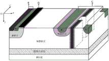
如图4所示,本例的具有可控集电极槽的SOI LIGBT,包括自下而上的衬底层1、绝缘介质层2和N型漂移区3;所述N型漂移区3一端包括发射极结构和栅极结构,另一端包括集电极结构和集电极槽结构。As shown in Figure 4, the SOI LIGBT with a controllable collector groove in this example includes a bottom-up
所述的发射极结构包括P阱区4、P+体接触区5和N+发射区6,所述P+体接触区5和所述N+发射区6位于所述P阱区4上表面,且所述N+发射区6位于所述P+体接触区5两侧,所述P+体接触区5和N+发射区6的共同引出端为发射极;其特征包括:所述的栅极结构包括平面栅结构和多个槽栅结构,所述的槽栅结构包括:位于P阱区4远离N型漂移区3的一侧的第一槽栅介质层72和所述第一槽栅介质层72中的第一槽栅多晶硅层82,且所述第一槽栅介质层72与N+发射区6和P阱区4接触;位于P阱区4靠近N型漂移区3一侧的分段式槽栅,包含第二槽栅介质层73和所述第二槽栅介质层73中的第二槽栅多晶硅层83,且所述第二槽栅介质层73一侧与N+发射区6和P阱区4接触,另一侧与N型漂移区3接触;所述的槽栅结构的结深大于所述的P阱区4的结深;所述的平面栅结构包括栅介质层71和所述栅介质层71之上的栅多晶硅层81,所述栅介质层71位于所述P阱区4之上且与所述N+发射区6有部分交叠;所述平面栅结构覆盖分段式第二槽栅介质层73之间的N型漂移区3;所述栅多晶硅层81、第一槽栅多晶硅层82与第二槽栅多晶硅层83的共同引出端为栅极;The emitter structure includes a
所述集电极结构包括P+集电区9和N+集电区10,所述P+集电区9位于所述N型漂移区3上表面,所述N+集电区10位于所述P+集电区9上表面;所述P+集电区9和所述N+集电区10的共同引出端为集电极;其特征在于:所述集电极槽结构横向穿过所述N+集电区10和P+集电区9,并延伸到所述N型漂移区3中,纵向深度大于P+集电区9;所述集电极槽结构包括槽介质层12和槽多晶硅层13组成,所述槽多晶硅层13的引出端为槽集电极。所述的槽集电极与集电极之间存在偏置电压:器件导通时槽集电极相对于集电极的电压为负值,器件关断时槽集电极相对于集电极的电压为正值。The collector structure includes a
本例的工作原理为:This example works as follows:
新器件正向导通时,槽集电极相对于集电极的偏置电压为负值,集电极槽侧壁形成高浓度的P型反型层,折叠的集电极槽结构增加了空穴注入面积,从而增强器件空穴注入效率,而且集电极一侧的分段式槽栅结构起到空穴阻挡层作用;因此,器件漂移区内空穴-电子浓度得到有效提高,从而降低器件正向导通压降;同时,由于N+集电区位于P+集电区上表面,未与N型漂移区接触,因此新器件没有电压折回效应。新器件关断时,槽集电极相对于集电极的偏置电压为正值,集电极槽侧壁形成高浓度的N型积累层,使得N+集电区与N型漂移区短接,形成电子的快速抽取路径,有利迅速抽取漂移区内电子;而且由于N+集电区与N型漂移区短接,P+集电区与N型漂移区之间几乎等电位,从而抑制集电极端空穴注入,提高器件关断速度;同时,集电极槽与槽壁形成的N型积累层一起作为等效的N型缓冲层,使得器件能承受高耐压。在工艺制备方面,新器件的槽集电极结构与槽栅结构可以采用相同的工艺步骤同时完成。When the new device is forward-conducting, the bias voltage of the groove collector relative to the collector is negative, and a high-concentration P-type inversion layer is formed on the side wall of the collector groove, and the folded collector groove structure increases the hole injection area. In this way, the hole injection efficiency of the device is enhanced, and the segmented groove gate structure on the collector side acts as a hole blocking layer; therefore, the hole-electron concentration in the drift region of the device is effectively increased, thereby reducing the forward voltage of the device At the same time, since the N+ collector region is located on the upper surface of the P+ collector region and is not in contact with the N-type drift region, the new device has no voltage foldback effect. When the new device is turned off, the bias voltage of the trough collector relative to the collector is positive, and a high-concentration N-type accumulation layer is formed on the side wall of the collector trough, so that the N+ collector region and the N-type drift region are short-circuited to form electrons. The fast extraction path is beneficial to quickly extract electrons in the drift region; and because the N+ collector region and the N-type drift region are short-circuited, the P+ collector region and the N-type drift region are almost equipotential, thereby suppressing hole injection at the collector terminal , improve the turn-off speed of the device; at the same time, the N-type accumulation layer formed by the collector groove and the groove wall acts as an equivalent N-type buffer layer, so that the device can withstand high withstand voltage. In terms of process preparation, the trench collector structure and the trench gate structure of the new device can be completed simultaneously using the same process steps.
本发明的有益效果为,相对于传统短路阳极-LIGBT结构,本发明具有更快的关断速度与更低的正向导通压降,而且没有电压折回效应。The beneficial effect of the present invention is that, compared with the traditional short-circuited anode-LIGBT structure, the present invention has faster turn-off speed and lower forward conduction voltage drop, and has no voltage foldback effect.
实施例2Example 2
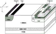
如图5所示,本例与实施例1的区别在于,本例中集电极结构端引入了N型缓冲层11,且集电极槽结构横向穿过N+集电区10、P+集电区9和N型缓冲层11,并延伸到所述N型漂移区3中,纵向深度大于N型缓冲层11。器件正向导通时,其工作机理与实施例1中一致;新器件关断时,槽集电极相对于集电极的偏置电压为正电位,集电极槽侧壁形成高浓度的N型积累层,此时集电极槽、槽壁N型积累层与N型缓冲层11一起起到电场截止作用,使得器件能承受高耐压。与实施例1相比,本例中新器件能获得更稳健的耐压特性。As shown in Figure 5, the difference between this example and Example 1 is that an N-
实施例3Example 3
如图6所示,本例与实施例2的区别在于,本例中集电极槽结构中槽介质层12下表面与绝缘介质层2的上表面连接。与实施例2相比,本例中新器件能获得更高的空穴注入效率与更低的正向导通压降。As shown in FIG. 6 , the difference between this example and Example 2 is that in this example, the lower surface of the trench
Claims (4)
Translated fromChinesePriority Applications (1)
| Application Number | Priority Date | Filing Date | Title |
|---|---|---|---|
| CN201710768209.6ACN107342321B (en) | 2017-08-31 | 2017-08-31 | SOI LIGBT with controllable collector electrode slot |
Applications Claiming Priority (1)
| Application Number | Priority Date | Filing Date | Title |
|---|---|---|---|
| CN201710768209.6ACN107342321B (en) | 2017-08-31 | 2017-08-31 | SOI LIGBT with controllable collector electrode slot |
Publications (2)
| Publication Number | Publication Date |
|---|---|
| CN107342321A CN107342321A (en) | 2017-11-10 |
| CN107342321Btrue CN107342321B (en) | 2023-03-31 |
Family
ID=60214832
Family Applications (1)
| Application Number | Title | Priority Date | Filing Date |
|---|---|---|---|
| CN201710768209.6AActiveCN107342321B (en) | 2017-08-31 | 2017-08-31 | SOI LIGBT with controllable collector electrode slot |
Country Status (1)
| Country | Link |
|---|---|
| CN (1) | CN107342321B (en) |
Families Citing this family (8)
| Publication number | Priority date | Publication date | Assignee | Title |
|---|---|---|---|---|
| CN108389900B (en)* | 2018-03-19 | 2020-05-26 | 电子科技大学 | A trench gate short-circuit anode SOI LIGBT |
| CN110504307B (en)* | 2019-08-28 | 2023-03-14 | 重庆邮电大学 | SA-LIGBT device with grid-controlled collector |
| CN110504309B (en)* | 2019-08-29 | 2020-09-29 | 电子科技大学 | High-speed low-power-consumption high-voltage power device |
| CN110504168B (en)* | 2019-08-29 | 2020-08-28 | 电子科技大学 | Manufacturing method of multi-groove-grid transverse high-voltage power device |
| CN111969049B (en)* | 2020-08-28 | 2022-08-23 | 电子科技大学 | SOI transverse insulated gate bipolar transistor |
| CN113066862B (en)* | 2021-03-25 | 2022-04-22 | 电子科技大学 | An Integrated MOS Adaptive Control SOI LIGBT |
| CN115832036B (en)* | 2022-11-21 | 2025-04-18 | 电子科技大学 | An adaptive high-voltage and low-loss power device |
| CN118888579B (en)* | 2024-09-27 | 2025-03-07 | 湖南杰楚微半导体科技有限公司 | Lateral insulated gate bipolar transistor device and preparation method thereof |
Citations (10)
| Publication number | Priority date | Publication date | Assignee | Title |
|---|---|---|---|---|
| US5796125A (en)* | 1994-09-16 | 1998-08-18 | Kabushiki Kaisha Toshiba | High breakdown voltage semiconductor device using trench grooves |
| JP2005217202A (en)* | 2004-01-29 | 2005-08-11 | Fuji Electric Holdings Co Ltd | Trench lateral semiconductor device and manufacturing method thereof |
| CN101553932A (en)* | 2006-11-30 | 2009-10-07 | 飞兆半导体公司 | Integrated latch-up free insulated gate bipolar transistor |
| CN101694850A (en)* | 2009-10-16 | 2010-04-14 | 电子科技大学 | Carrier-storing grooved gate IGBT with P-type floating layer |
| CN103531619A (en)* | 2012-07-06 | 2014-01-22 | 台湾积体电路制造股份有限公司 | Lateral insulated gate bipolar transistor structure with low parasitic bjt gain and stable threshold voltage |
| CN104465379A (en)* | 2013-09-18 | 2015-03-25 | 中芯国际集成电路制造(上海)有限公司 | Semiconductor device and forming method thereof |
| CN105826367A (en)* | 2016-03-18 | 2016-08-03 | 东南大学 | Large-current silicon on insulator lateral insulated gate bipolar transistor device |
| CN106847888A (en)* | 2017-03-19 | 2017-06-13 | 北京工业大学 | A kind of colelctor electrode IGBT with vertical field plate structure |
| CN106920842A (en)* | 2017-05-11 | 2017-07-04 | 电子科技大学 | A kind of groove profile SOI LIGBT with carrier accumulation layer |
| CN207233738U (en)* | 2017-08-31 | 2018-04-13 | 电子科技大学 | A kind of SOI LIGBT with controllable collector groove |
- 2017
- 2017-08-31CNCN201710768209.6Apatent/CN107342321B/enactiveActive
Patent Citations (10)
| Publication number | Priority date | Publication date | Assignee | Title |
|---|---|---|---|---|
| US5796125A (en)* | 1994-09-16 | 1998-08-18 | Kabushiki Kaisha Toshiba | High breakdown voltage semiconductor device using trench grooves |
| JP2005217202A (en)* | 2004-01-29 | 2005-08-11 | Fuji Electric Holdings Co Ltd | Trench lateral semiconductor device and manufacturing method thereof |
| CN101553932A (en)* | 2006-11-30 | 2009-10-07 | 飞兆半导体公司 | Integrated latch-up free insulated gate bipolar transistor |
| CN101694850A (en)* | 2009-10-16 | 2010-04-14 | 电子科技大学 | Carrier-storing grooved gate IGBT with P-type floating layer |
| CN103531619A (en)* | 2012-07-06 | 2014-01-22 | 台湾积体电路制造股份有限公司 | Lateral insulated gate bipolar transistor structure with low parasitic bjt gain and stable threshold voltage |
| CN104465379A (en)* | 2013-09-18 | 2015-03-25 | 中芯国际集成电路制造(上海)有限公司 | Semiconductor device and forming method thereof |
| CN105826367A (en)* | 2016-03-18 | 2016-08-03 | 东南大学 | Large-current silicon on insulator lateral insulated gate bipolar transistor device |
| CN106847888A (en)* | 2017-03-19 | 2017-06-13 | 北京工业大学 | A kind of colelctor electrode IGBT with vertical field plate structure |
| CN106920842A (en)* | 2017-05-11 | 2017-07-04 | 电子科技大学 | A kind of groove profile SOI LIGBT with carrier accumulation layer |
| CN207233738U (en)* | 2017-08-31 | 2018-04-13 | 电子科技大学 | A kind of SOI LIGBT with controllable collector groove |
Non-Patent Citations (4)
| Title |
|---|
| Dual-channel SOI LIGBT with improved latch-up and forward voltage drop characteristics;Woo-Beom Choi,etc;《Device Research Conference. Conference Digest》;Institute of Electrical and Electronics Engineers;20020807;全文* |
| Trench Emitter IGBT with Lateral;Young-Su Kang,etc;《2002 23rd International Conference on Microelectronics. Proceedings 》;nstitute of Electrical and Electronics Engineers;20020807;全文* |
| 双槽栅SOI LDMOS器件结构及其制造方法研究;许生根等;《科技通报》;20110315(第02期);全文* |
| 漂移区均匀掺杂SOILIGBT通态电阻模型;徐文杰等;《杭州电子科技大学学报》;20070415(第02期);全文* |
Also Published As
| Publication number | Publication date |
|---|---|
| CN107342321A (en) | 2017-11-10 |
Similar Documents
| Publication | Publication Date | Title |
|---|---|---|
| CN107342321B (en) | SOI LIGBT with controllable collector electrode slot | |
| CN108321195B (en) | A short-circuit anode SOI LIGBT with anode pinch-off groove | |
| CN110504308B (en) | High-speed low-loss multi-groove-gate high-voltage power device | |
| CN110491937B (en) | An IGBT with a self-biased split gate structure | |
| CN108389900A (en) | A kind of slot grid short circuit anode SOI LIGBT | |
| CN105932055B (en) | A kind of planar gate IGBT and preparation method thereof | |
| CN108321194B (en) | A SOI LIGBT with fast turn-off characteristics | |
| CN106298900A (en) | A kind of high speed SOI LIGBT | |
| CN108122963B (en) | Potential control rapid transverse insulated gate bipolar transistor | |
| CN111816699A (en) | An adaptive SOI LIGBT device | |
| CN114823863B (en) | Low-power-consumption transverse power device with anode groove | |
| CN111816698B (en) | Power device integrated with Zener diode and collector PMOS structure | |
| CN107464842A (en) | A kind of superjunction with colelctor electrode groove is against conductivity type IGBT | |
| CN106920842A (en) | A kind of groove profile SOI LIGBT with carrier accumulation layer | |
| CN108493241A (en) | A kind of IGBT device with built-in JFET structures | |
| CN105870181A (en) | Plane gate IGBT (insulated gate bipolar translator) and manufacturing method thereof | |
| US9263560B2 (en) | Power semiconductor device having reduced gate-collector capacitance | |
| CN105489644B (en) | IGBT device and preparation method thereof | |
| CN105789291A (en) | Double split trench gate charge storage type insulated gate bipolar transistor (IGBT) and manufacturing method thereof | |
| CN116454127A (en) | A SOI LIGBT with low turn-off loss | |
| CN113066862B (en) | An Integrated MOS Adaptive Control SOI LIGBT | |
| CN207233738U (en) | A kind of SOI LIGBT with controllable collector groove | |
| CN111834450A (en) | A SOI LIGBT device with integrated Zener diode | |
| CN114883395B (en) | IGBT with partial P-type drift region | |
| CN108767001B (en) | Trench IGBT device with shielding gate |
Legal Events
| Date | Code | Title | Description |
|---|---|---|---|
| PB01 | Publication | ||
| PB01 | Publication | ||
| SE01 | Entry into force of request for substantive examination | ||
| SE01 | Entry into force of request for substantive examination | ||
| GR01 | Patent grant | ||
| GR01 | Patent grant |