CN107340923B - Sensor device, input device, electronic device, and information processing method - Google Patents
Sensor device, input device, electronic device, and information processing methodDownload PDFInfo
- Publication number
- CN107340923B CN107340923BCN201710571512.7ACN201710571512ACN107340923BCN 107340923 BCN107340923 BCN 107340923BCN 201710571512 ACN201710571512 ACN 201710571512ACN 107340923 BCN107340923 BCN 107340923B
- Authority
- CN
- China
- Prior art keywords
- state
- input
- input device
- capacitive element
- electrode
- Prior art date
- Legal status (The legal status is an assumption and is not a legal conclusion. Google has not performed a legal analysis and makes no representation as to the accuracy of the status listed.)
- Expired - Fee Related
Links
Images


Classifications
- G—PHYSICS
- G06—COMPUTING OR CALCULATING; COUNTING
- G06F—ELECTRIC DIGITAL DATA PROCESSING
- G06F3/00—Input arrangements for transferring data to be processed into a form capable of being handled by the computer; Output arrangements for transferring data from processing unit to output unit, e.g. interface arrangements
- G06F3/01—Input arrangements or combined input and output arrangements for interaction between user and computer
- G06F3/03—Arrangements for converting the position or the displacement of a member into a coded form
- G06F3/041—Digitisers, e.g. for touch screens or touch pads, characterised by the transducing means
- G06F3/0416—Control or interface arrangements specially adapted for digitisers
- G—PHYSICS
- G06—COMPUTING OR CALCULATING; COUNTING
- G06F—ELECTRIC DIGITAL DATA PROCESSING
- G06F3/00—Input arrangements for transferring data to be processed into a form capable of being handled by the computer; Output arrangements for transferring data from processing unit to output unit, e.g. interface arrangements
- G06F3/01—Input arrangements or combined input and output arrangements for interaction between user and computer
- G06F3/03—Arrangements for converting the position or the displacement of a member into a coded form
- G06F3/041—Digitisers, e.g. for touch screens or touch pads, characterised by the transducing means
- G06F3/044—Digitisers, e.g. for touch screens or touch pads, characterised by the transducing means by capacitive means
- G06F3/0445—Digitisers, e.g. for touch screens or touch pads, characterised by the transducing means by capacitive means using two or more layers of sensing electrodes, e.g. using two layers of electrodes separated by a dielectric layer
- G—PHYSICS
- G06—COMPUTING OR CALCULATING; COUNTING
- G06F—ELECTRIC DIGITAL DATA PROCESSING
- G06F3/00—Input arrangements for transferring data to be processed into a form capable of being handled by the computer; Output arrangements for transferring data from processing unit to output unit, e.g. interface arrangements
- G06F3/01—Input arrangements or combined input and output arrangements for interaction between user and computer
- G06F3/03—Arrangements for converting the position or the displacement of a member into a coded form
- G06F3/041—Digitisers, e.g. for touch screens or touch pads, characterised by the transducing means
- G06F3/044—Digitisers, e.g. for touch screens or touch pads, characterised by the transducing means by capacitive means
- G06F3/0446—Digitisers, e.g. for touch screens or touch pads, characterised by the transducing means by capacitive means using a grid-like structure of electrodes in at least two directions, e.g. using row and column electrodes
- G—PHYSICS
- G06—COMPUTING OR CALCULATING; COUNTING
- G06F—ELECTRIC DIGITAL DATA PROCESSING
- G06F3/00—Input arrangements for transferring data to be processed into a form capable of being handled by the computer; Output arrangements for transferring data from processing unit to output unit, e.g. interface arrangements
- G06F3/01—Input arrangements or combined input and output arrangements for interaction between user and computer
- G06F3/03—Arrangements for converting the position or the displacement of a member into a coded form
- G06F3/041—Digitisers, e.g. for touch screens or touch pads, characterised by the transducing means
- G06F3/044—Digitisers, e.g. for touch screens or touch pads, characterised by the transducing means by capacitive means
- G06F3/0448—Details of the electrode shape, e.g. for enhancing the detection of touches, for generating specific electric field shapes, for enhancing display quality
Landscapes
- Engineering & Computer Science (AREA)
- General Engineering & Computer Science (AREA)
- Theoretical Computer Science (AREA)
- Human Computer Interaction (AREA)
- Physics & Mathematics (AREA)
- General Physics & Mathematics (AREA)
- Switches That Are Operated By Magnetic Or Electric Fields (AREA)
- Position Input By Displaying (AREA)
- Input From Keyboards Or The Like (AREA)
Abstract
Translated fromChinese
Description
Translated fromChinese本申请是申请日2013年01月18日、申请号为201310019716.1、发明名称为“传感器装置、输入装置、电子设备及信息处理方法”的申请的分案申请。This application is a divisional application of the application dated January 18, 2013, the application number is 201310019716.1, and the invention title is "sensor device, input device, electronic device and information processing method".
技术领域technical field
本公开涉及包括电容元件的传感器装置、输入装置、电子设备以及信息处理方法。The present disclosure relates to a sensor device, an input device, an electronic device, and an information processing method including a capacitive element.
背景技术Background technique
众所周知,包括电容元件的触摸型输入装置是用于电子设备的输入装置。例如,日本专利申请公开第2011-197991号公开了不仅能够检测操作元件的触摸操作还可以检测其按压操作的输入装置。As is well known, a touch-type input device including a capacitive element is an input device for electronic equipment. For example, Japanese Patent Application Laid-Open No. 2011-197991 discloses an input device capable of detecting not only a touch operation of an operating element but also a pressing operation thereof.
发明内容SUMMARY OF THE INVENTION
然而,在日本专利申请公开第2011-197991号中所公开的技术中,所采用的检测操作元件的按压操作的配置独立于检测是否进行了操作元件的触摸操作的配置。因此,在上面的技术中,输入装置的整体配置很复杂。However, in the technique disclosed in Japanese Patent Application Laid-Open No. 2011-197991, a configuration for detecting a pressing operation of an operating element is adopted independently of a configuration for detecting whether a touch operation of the operating element is performed. Therefore, in the above technique, the overall configuration of the input device is complicated.
考虑到如上所述的情况,最好提供一种具有简单配置并能够检测操作元件的触摸操作和按压操作的传感器装置、输入装置和电子设备。In view of the situation as described above, it is desirable to provide a sensor device, an input device, and an electronic device that have a simple configuration and can detect a touch operation and a pressing operation of an operating element.
根据本公开的实施方式,提出了一种包括电容元件和输入操作单元的传感器装置。According to an embodiment of the present disclosure, a sensor device including a capacitive element and an input operation unit is proposed.
电容元件具有第一表面并被配置为通过将操作元件接近第一表面来改变其电容。输入操作单元布置在第一表面上。输入操作单元具有在其上接收操作元件的操作的第二表面,并被配置为允许与第二表面接触的操作元件向第一表面移动。The capacitive element has a first surface and is configured to change its capacitance by bringing the operating element close to the first surface. The input operation unit is arranged on the first surface. The input operation unit has a second surface on which the operation of the operation element is received, and is configured to allow the operation element in contact with the second surface to move toward the first surface.
用这种配置,传感器装置使得电容元件在操作元件在输入操作单元上所作出的触摸操作和按压操作之间具有不同的电容变化量。With this configuration, the sensor device causes the capacitive element to have a different amount of capacitance change between the touch operation and the pressing operation made by the operating element on the input operation unit.
第二表面可包括多个凹部。The second surface may include a plurality of recesses.
用这种配置,由于在输入操作单元上用操作元件所进行的按压操作,操作元件弹性变形并进入凹部,从而接近电容元件。With this configuration, due to the pressing operation with the operating element on the input operating unit, the operating element is elastically deformed and enters the concave portion, thereby approaching the capacitive element.
第二表面可由弹性材料形成。The second surface may be formed of an elastic material.
用这种配置,由于在输入操作单元上用操作元件所进行的按压操作,操作元件弹性变形并进入凹部,并且弹性材料变形。因此,操作元件接近电容元件。With this configuration, due to the pressing operation with the operating element on the input operating unit, the operating element is elastically deformed and enters the recess, and the elastic material is deformed. Therefore, the operating element is close to the capacitive element.
输入操作单元可包括形成第二表面的弹性体。The input operation unit may include an elastic body forming the second surface.
用这种配置,由于在输入操作单元上用操作元件所进行的按压操作,弹性体变形。因此,操作元件接近电容元件。With this configuration, the elastic body is deformed due to the pressing operation with the operating element on the input operating unit. Therefore, the operating element is close to the capacitive element.
输入操作单元可被布置在第一表面和第二表面之间,并还包括被配置为以弹性可变形的方式支持弹性体的支持部。The input operation unit may be disposed between the first surface and the second surface, and further include a support portion configured to support the elastic body in an elastically deformable manner.
用这种配置,由于在输入操作单元上用操作元件所进行的按压操作,弹性体变形。因此,操作元件接近电容元件。With this configuration, the elastic body is deformed due to the pressing operation with the operating element on the input operating unit. Therefore, the operating element is close to the capacitive element.
根据本公开的另一个实施方式,提出了一种至少包括一个传感器和控制器的输入装置。According to another embodiment of the present disclosure, an input device including at least one sensor and a controller is provided.
该至少一个传感器包括电容元件和输入操作单元。电容元件具有第一表面并被配置为通过将操作元件接近第一表面改变其电容。输入操作单元被布置在所述第一表面上。输入操作单元具有在其上接收操作元件的操作的第二表面,并被配置为允许与第二表面接触的操作元件向第一表面移动。控制器包括:判定单元,被配置为基于所述电容元件的电容的改变,判定第一状态以及从第一状态向第二状态的改变,第一状态是操作元件与第二表面接触的状态,第二状态是操作元件按压第二表面的状态。The at least one sensor includes a capacitive element and an input manipulation unit. The capacitive element has a first surface and is configured to change its capacitance by bringing the operating element close to the first surface. An input operation unit is arranged on the first surface. The input operation unit has a second surface on which the operation of the operation element is received, and is configured to allow the operation element in contact with the second surface to move toward the first surface. The controller includes a determination unit configured to determine a first state and a change from the first state to a second state based on a change in capacitance of the capacitive element, the first state being a state in which the operating element is in contact with the second surface, The second state is a state in which the operating element presses the second surface.
用这种配置,在输入装置中,控制器的判定单元能基于电容元件的电容的变化量判定用操作元件在输入操作单元所进行的触摸操作和按压操作。With this configuration, in the input device, the determination unit of the controller can determine the touch operation and the pressing operation performed at the input operation unit with the operation element based on the amount of change in the capacitance of the capacitive element.
判定单元可被配置为当电容元件的电容变化量等于或大于第一阈值时判定为第一状态,而当电容变化量等于或大于第二阈值时判定为第二状态,第二阈值大于第一阈值。The determination unit may be configured to determine the first state when the capacitance change amount of the capacitive element is equal to or greater than a first threshold value, and determine the second state when the capacitance change amount is equal to or greater than a second threshold value greater than the first threshold value threshold.
用这种配置,判定单元可利用第一阈值和第二阈值容易地区分操作元件的触摸操作和按压操作。With this configuration, the determination unit can easily distinguish the touch operation and the pressing operation of the operating element using the first threshold value and the second threshold value.
该至少一个传感器可包括多个传感器,并且所述多个传感器可包括分别具有不同的第二阈值的多个传感器。The at least one sensor may include a plurality of sensors, and the plurality of sensors may include a plurality of sensors each having a different second threshold value.
用这种配置,对于每个传感器,可改变在按压操作时的所谓的“按键权重(keyweight)”。With this configuration, a so-called "keyweight" at the time of the pressing operation can be changed for each sensor.
输入装置可进一步包括被配置为存储对于至少一个传感器来说唯一的第一阈值和第二阈值的数据的存储器。控制器可被配置为控制存储器以能够响应外部的指令而改变存储于存储器中的数据。The input device may further include a memory configured to store data for the first and second thresholds unique to the at least one sensor. The controller may be configured to control the memory to be able to change data stored in the memory in response to external instructions.
用这种配置,每个传感器关于触摸操作和按压操作的检测灵敏度可被改变。With this configuration, the detection sensitivity of each sensor with respect to the touch operation and the pressing operation can be changed.
控制器可进一步包括:信号生成单元,被配置为生成在第一状态和第二状态之间不同的操作信号。The controller may further include: a signal generating unit configured to generate an operation signal that is different between the first state and the second state.
用这种配置,控制器可使输出装置进行在输入操作单元上用操作元件所进行的触摸操作和按压操作间不同的动作。With this configuration, the controller can make the output device perform different actions between a touch operation and a pressing operation performed with the operating element on the input operation unit.
该至少一个传感器可包括多个传感器,多个传感器可包括关于操作元件的接近分别具有不同电容元件检测灵敏度的多个传感器。The at least one sensor may include a plurality of sensors, and the plurality of sensors may include a plurality of sensors each having different detection sensitivities of the capacitive element with respect to the approach of the operating element.
进一步地,所述多个传感器可包括分别具有不同数量的电容元件的多个传感器。Further, the plurality of sensors may include a plurality of sensors each having a different number of capacitive elements.
用这种配置,多个传感器中的每一个传感器可基于在输入装置上的传感器的布置等来调整关于操作元件的触摸和按压操作的检测灵敏度。With this configuration, each of the plurality of sensors can adjust the detection sensitivity with respect to the touch and pressing operation of the operating element based on the arrangement of the sensors on the input device and the like.
根据本公开的另一个实施方式,提出了一种电子设备,包括至少一个传感器、控制器、处理装置和输出装置。According to another embodiment of the present disclosure, an electronic device is proposed, including at least one sensor, a controller, a processing device, and an output device.
该至少一个传感器包括电容元件和输入操作单元。电容元件具有第一表面并被配置为通过操作元件接近第一表面来改变其电容。输入操作单元被布置在第一表面上。输入操作单元具有其上接收操作元件的操作的第二表面并被配置为允许与第二表面接触的操作元件向第一表面移动。控制器包括判定单元和信号生成单元。判定单元被配置为基于电容元件电容的改变判定第一状态以及从第一状态到第二状态的改变,第一状态是其中操作元件与第二表面接触的状态,第二状态是其中操作元件按压第二表面的状态。信号生成单元被配置为生成在第一状态和第二状态之间不同的操作信号。处理装置被配置为基于操作信号生成命令信号。输出装置被配置为基于命令信号进行输出。The at least one sensor includes a capacitive element and an input manipulation unit. The capacitive element has a first surface and is configured to vary its capacitance by manipulating the element's proximity to the first surface. The input operation unit is arranged on the first surface. The input operation unit has a second surface on which an operation of the operating element is received and is configured to allow the operating element in contact with the second surface to move toward the first surface. The controller includes a determination unit and a signal generation unit. The determination unit is configured to determine a first state in which the operating element is in contact with the second surface and a change from the first state to a second state in which the operating element is pressed based on a change in capacitance of the capacitive element The state of the second surface. The signal generating unit is configured to generate operating signals that differ between the first state and the second state. The processing device is configured to generate the command signal based on the operating signal. The output device is configured to output based on the command signal.
用这种配置,在输入装置中,使得输出装置可以进行在用操作元件在输入操作单元上所进行的触摸操作和按压操作之间的不同的动作。With this configuration, in the input device, the output device is allowed to perform a different action between a touch operation and a pressing operation performed on the input operation unit with the operating element.
输出装置可包括被配置为基于命令信号显示图像的显示装置。The output device may include a display device configured to display an image based on the command signal.
用这种配置,电子设备可使得输入装置生成操作信号并通过操作信号使得显示装置显示基于命令信号的图像。With this configuration, the electronic device can cause the input device to generate the operation signal and cause the display device to display the image based on the command signal through the operation signal.
控制器可被配置为当电容元件的电容变化量等于或大于第一阈值并小于第二阈值时,判定为第一状态;当电容变化量等于或大于第二阈值时,判定为第二状态。The controller may be configured to determine the first state when the capacitance change of the capacitive element is equal to or greater than the first threshold and less than the second threshold; and determine the second state when the capacitance change is equal to or greater than the second threshold.
用这种配置,可判定每个传感器处于第一状态还是处于第二状态。With this configuration, it can be determined whether each sensor is in the first state or in the second state.
在电子装置中,所述至少一个传感器可包括多个传感器。电子设备还可包括:存储器,被配置为存储关于第一阈值和第二阈值的数据,第一阈值和第二阈值对于多个传感器中的每一个是唯一的。控制器可被配置为控制存储器以能够响应来自外部的指令而改变存储在存储器内的数据。In the electronic device, the at least one sensor may include a plurality of sensors. The electronic device may also include a memory configured to store data regarding the first threshold and the second threshold, the first and second thresholds being unique to each of the plurality of sensors. The controller may be configured to control the memory to be able to change data stored in the memory in response to instructions from the outside.
根据本公开的另一实施方式,提出了一种使用包括至少一个传感器的电子设备的信息处理方法,其中至少一个传感器包括具有第一表面并被配置为通过操作元件接近第一表面来改变其电容的电容元件,输入操作单元被布置在第一表面,输入操作单元具有其上接收操作元件操作的第二表面,并被配置为允许接触第二表面的操作元件向第一表面移动,信息处理方法包括:当电容变化量等于或大于第一阈值时,判定为其中操作元件接触第二表面的第一状态;当电容变化量等于或大于比第一阈值大的第二阈值时,判定为其中操作元件按压第二表面的第二状态。According to another embodiment of the present disclosure, an information processing method using an electronic device including at least one sensor is proposed, wherein the at least one sensor includes a first surface and is configured to change its capacitance by approaching the first surface by an operating element the capacitive element, the input operation unit is arranged on the first surface, the input operation unit has a second surface on which the operation of the operation element is received, and is configured to allow the operation element contacting the second surface to move toward the first surface, information processing method Including: when the capacitance change amount is equal to or greater than the first threshold, it is determined that the operating element is in a first state in which the operating element is in contact with the second surface; when the capacitance change amount is equal to or greater than a second threshold value greater than the first threshold value, it is determined that the operation is in which A second state in which the element is pressed against the second surface.
信息处理方法可进一步包括:基于用户的操作,从判定第一状态和第二状态的输入操作模式切换到改变第二阈值的改变模式。The information processing method may further include switching from an input operation mode of determining the first state and the second state to a change mode of changing the second threshold value based on a user's operation.
此外,至少一个传感器可包括多个传感器,切换到改变模式可包括将一部分传感器的第二阈值改变为不同于其他传感器的第二阈值的值。Additionally, the at least one sensor may include a plurality of sensors, and switching to the change mode may include changing the second threshold of a portion of the sensors to a value different from the second threshold of other sensors.
此外,改变第二阈值可包括接收一部分传感器的第二阈值的输入并基于输入指令值改变第二阈值。Further, changing the second threshold may include receiving an input of the second threshold of a portion of the sensors and changing the second threshold based on the input command value.
如上文所述,根据本公开,可以提供具有简单配置并包括能够检测操作元件的触摸和按压的电容元件的传感器装置、输入装置和电子设备,并提供信息处理方法。As described above, according to the present disclosure, it is possible to provide a sensor device, an input device, and an electronic device having a simple configuration and including a capacitive element capable of detecting touch and pressing of an operation element, and an information processing method.
根据以下对如附图所示的具体实施方式的详述,本公开的这些和其他目标、特征和优点将更加明显。These and other objects, features and advantages of the present disclosure will be more apparent from the following detailed description of specific embodiments as illustrated in the accompanying drawings.
附图说明Description of drawings
图1是根据本公开第一实施方式的输入装置的透视图;1 is a perspective view of an input device according to a first embodiment of the present disclosure;
图2A到图2C是输入装置沿图1所示的A-A`线的截面图;2A to 2C are cross-sectional views of the input device taken along the line A-A' shown in FIG. 1;
图3是包括图1所示的输入装置的电子设备的框图;3 is a block diagram of an electronic device including the input device shown in FIG. 1;
图4A到图4E是示出图1所示的输入操作单元的变形例的图;4A to 4E are diagrams showing modifications of the input operation unit shown in FIG. 1;
图5A到图5J是示出图1中所示的输入操作单元的变形例的图;5A to 5J are diagrams showing modifications of the input operation unit shown in FIG. 1;
图6A到图6C是示出图1中所示的制造输入操作单元的方法的图;6A to 6C are diagrams showing a method of manufacturing the input operation unit shown in FIG. 1;
图7A到图7C是示出制造输入操作单元的方法的变形例的图;7A to 7C are diagrams showing a modification of the method of manufacturing the input operation unit;
图8A到图8C是示出制造输入操作单元的方法的变形例的图;8A to 8C are diagrams showing a modification of the method of manufacturing the input operation unit;
图9是示出图1所示的输入装置的电极配置的图;FIG. 9 is a diagram showing an electrode configuration of the input device shown in FIG. 1;
图10是示出输入装置的电极配置的变形例的图;10 is a diagram showing a modification of the electrode arrangement of the input device;
图11是示出图1中所示的输入装置的输出信号的示例的图;FIG. 11 is a diagram showing an example of an output signal of the input device shown in FIG. 1;
图12是图1所示的输入装置的电容变化速度的说明图;12 is an explanatory diagram of a capacitance change rate of the input device shown in FIG. 1;
图13是示出图1所示的输入装置示例的平面图;13 is a plan view showing an example of the input device shown in FIG. 1;
图14是示出输入装置的电极配置的变形例的图;14 is a diagram showing a modification of the electrode arrangement of the input device;
图15是示出了包括图1所示输入装置的个人计算机的配置的示意图;15 is a schematic diagram showing a configuration of a personal computer including the input device shown in FIG. 1;
图16是示出了图15所示的个人计算机的配置的示意图;Fig. 16 is a schematic diagram showing the configuration of the personal computer shown in Fig. 15;
图17是示出了图15所示的个人计算机的配置的示意图;17 is a schematic diagram showing the configuration of the personal computer shown in FIG. 15;
图18是示出了图15所示的个人计算机的配置的示意图;FIG. 18 is a schematic diagram showing the configuration of the personal computer shown in FIG. 15;
图19A和图19B是分别示出包括图1所示的输入装置的便携终端设备的配置的示意图;19A and 19B are schematic diagrams each showing a configuration of a portable terminal device including the input device shown in FIG. 1;
图20是示出包括图1所示的输入装置的成像设备的配置的示意图;20 is a schematic diagram showing a configuration of an imaging apparatus including the input device shown in FIG. 1;
图21A和图21B是分别示出包括图1中所示的输入装置的便携音乐播放器配置的示意图;21A and 21B are schematic diagrams respectively showing the configuration of a portable music player including the input device shown in FIG. 1;
图22A和图22B是分别示出包括图1中所示的输入装置的远程控制器的配置的示意图;22A and 22B are schematic diagrams each showing a configuration of a remote controller including the input device shown in FIG. 1;
图23A和图23B是分别示出包括图1中的输入装置的头载显示器的配置的示意图,并示出其中用户的手指未接近输入操作单元的初始状态;23A and 23B are schematic diagrams each showing a configuration of a head-mounted display including the input device in FIG. 1, and show an initial state in which the user's finger is not approaching the input operation unit;
图24A和图24B是分别示出包括图1中所示的输入装置的头载显示器的配置,并示出其中用户进行触摸操作的状态的示意图;24A and 24B are schematic diagrams showing a configuration of a head-mounted display including the input device shown in FIG. 1, respectively, and showing a state in which a user performs a touch operation;
图25A和图25B是分别示出包括图1所示的输入装置的头载显示器的配置,并示出其中用户进行按压操作的状态的示意图;25A and 25B are schematic diagrams showing a configuration of a head-mounted display including the input device shown in FIG. 1, respectively, and showing a state in which a user performs a pressing operation;
图26A到图26C是根据本公开第二实施方式的输入装置的截面图;26A to 26C are cross-sectional views of an input device according to a second embodiment of the present disclosure;
图27A到图27B是图26A到图26C所示的输入操作单元的放大截面图;27A to 27B are enlarged cross-sectional views of the input operation unit shown in FIGS. 26A to 26C;
图28A到图28C是根据本公开的第三实施方式的输入装置的截面图;28A to 28C are cross-sectional views of an input device according to a third embodiment of the present disclosure;
图29A到图29C是根据本公开第四实施方式的输入装置的截面图;29A to 29C are cross-sectional views of an input device according to a fourth embodiment of the present disclosure;
图30是根据本公开第五实施方式的输入装置的框图;30 is a block diagram of an input device according to a fifth embodiment of the present disclosure;
图31是图30所示的输入装置的部分截面图;Figure 31 is a partial cross-sectional view of the input device shown in Figure 30;
图32是示出图30所示的电容元件的制造示例的示意截面图;Fig. 32 is a schematic cross-sectional view showing a manufacturing example of the capacitive element shown in Fig. 30;
图33是示出图30的所示的电容元件制造示例的示意截面图;33 is a schematic cross-sectional view showing a manufacturing example of the capacitive element shown in FIG. 30;
图34是示出图30所示的输入操作单元的制造示例的示意性截面图;34 is a schematic cross-sectional view showing a manufacturing example of the input operation unit shown in FIG. 30;
图35是图30所示的输入装置的平面图,仅示出电容元件的配线图案;Fig. 35 is a plan view of the input device shown in Fig. 30, showing only the wiring pattern of the capacitive element;
图36是示出图30所示的第一电极的配置的平面图;Fig. 36 is a plan view showing the configuration of the first electrode shown in Fig. 30;
图37是示出图30所示的第二电极的配置的平面图;Fig. 37 is a plan view showing the configuration of the second electrode shown in Fig. 30;
图38A和图38B是用于描述图36和图37所示的第一和第二电极的作用的图,其示出根据第五实施方式的第一和第二电极的配置示例。38A and 38B are diagrams for describing the actions of the first and second electrodes shown in FIGS. 36 and 37 , which show a configuration example of the first and second electrodes according to the fifth embodiment.
图39A和图39B是用于描述图36和图37所示的第一和第二电极的作用的图,其示出了根据相关技术的第一和第二电极的配置示例;39A and 39B are diagrams for describing the actions of the first and second electrodes shown in FIGS. 36 and 37 , which show configuration examples of the first and second electrodes according to the related art;
图40A到图40P是分别示出图36所示的第一电极的变形例的图;40A to 40P are diagrams each showing a modification of the first electrode shown in FIG. 36;
图41是图30所示的输入装置的操作示例的流程图;Fig. 41 is a flowchart of an example of the operation of the input device shown in Fig. 30;
图42是图30所示传感器中的包括两个电容元件的传感器的示意性俯视图;Figure 42 is a schematic top view of a sensor including two capacitive elements in the sensor shown in Figure 30;
图43是根据本公开的第六实施方式的输入装置的框图;43 is a block diagram of an input device according to a sixth embodiment of the present disclosure;
图44是示出图43所示的传感器配置的示意截面图;Fig. 44 is a schematic cross-sectional view showing the sensor configuration shown in Fig. 43;
图45是其上放置金属板的传感器的示意截面图,用于说明检测图43所示的电容元件的电容变化的灵敏度的方法。FIG. 45 is a schematic cross-sectional view of a sensor on which a metal plate is placed, for explaining a method of detecting the sensitivity of the capacitance change of the capacitive element shown in FIG. 43 .
图46是示出图43所示的电容元件的电容变化量的表格的示例;FIG. 46 is an example of a table showing the capacitance change amount of the capacitive element shown in FIG. 43;
图47是示出其中图43所示的传感器包括四个电容元件的情况中电容元件的布置的示意平面图;47 is a schematic plan view showing the arrangement of capacitive elements in the case where the sensor shown in FIG. 43 includes four capacitive elements;
图48是示出图47中所示的相关电容元件的阈值设定的数据示例的图;FIG. 48 is a diagram showing an example of data of threshold value setting of the relevant capacitive element shown in FIG. 47;
图49A和图49B是输入装置的示意截面图,用于描述阈值数据的设定示例;49A and 49B are schematic cross-sectional views of an input device for describing a setting example of threshold value data;
图50A和图50B是分别示出图49A和49B中所示的传感器的电容元件的灵敏度评价值的数据示例的图,该灵敏度评价值基于由初始电容的电容变化量。FIGS. 50A and 50B are diagrams showing data examples of sensitivity evaluation values of the capacitive elements of the sensors shown in FIGS. 49A and 49B , which are based on the capacitance change amount by the initial capacitance, respectively.
图51是根据本公开的第七实施方式的电子设备的框图;51 is a block diagram of an electronic device according to a seventh embodiment of the present disclosure;
图52是示出在图51中所示的电子设备的监视器上显示的阈值设定图像的示例的图;52 is a diagram showing an example of a threshold value setting image displayed on a monitor of the electronic device shown in FIG. 51;
图53是示出图52中所示的阈值设定图像的示例的图,其中改变前的灵敏度评价值被显示在预定的单元格(cell)中;53 is a diagram showing an example of the threshold value setting image shown in FIG. 52, in which the sensitivity evaluation value before change is displayed in a predetermined cell;
图54示出了图52中所示的阈值设定图像的示例,其中,改变后的灵敏度评价值被显示在预定的单元格中;Fig. 54 shows an example of the threshold value setting image shown in Fig. 52 in which the changed sensitivity evaluation value is displayed in a predetermined cell;
图55是示出用作图51所示的电子设备的输入装置和平板终端的配置示例示意图;55 is a schematic diagram showing a configuration example of an input device and a tablet terminal used as the electronic apparatus shown in FIG. 51;
图56是示出用作图51所示的电子设备的输入装置和平板终端的配置示例示意图;56 is a schematic diagram showing a configuration example of an input device and a tablet terminal used as the electronic apparatus shown in FIG. 51;
图57是示出用作图51所示的电子设备的输入装置和平板终端的配置示例示意图;57 is a schematic diagram showing a configuration example of an input device and a tablet terminal used as the electronic apparatus shown in FIG. 51;
图58A和图58B是分别示出图30所示的输入装置的变形例的图,其示出了第一电极的配置示例;以及58A and 58B are diagrams each showing a modification of the input device shown in FIG. 30 , showing a configuration example of the first electrode; and
图59A到图59C是分别示出图30所示的输入装置的变形例的图,其示出了第二电极的配置示例。59A to 59C are diagrams each showing a modification of the input device shown in FIG. 30 , which shows a configuration example of the second electrode.
具体实施方式Detailed ways
下文中,将参照附图描述本公开的实施方式。附图示出了彼此正交的X轴、Y轴和Z轴。这些轴在下面的实施方式中是共同的。Hereinafter, embodiments of the present disclosure will be described with reference to the accompanying drawings. The figures show the X-axis, Y-axis and Z-axis which are orthogonal to each other. These axes are common to the following embodiments.
(第一实施方式)(first embodiment)
(整体配置)(overall configuration)
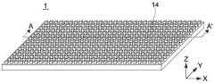
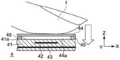
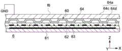
图1是根据本公开的第一实施方式的输入装置1的透视图。图2A到2C是输入装置1沿图1所示的A-A`线的局部截面图。图3是包括输入装置1的电子设备z的框图。FIG. 1 is a perspective view of an
输入装置1被形成为具有平板形并包括电容元件11和输入操作单元14。电容元件11和输入操作单元14组成了互电容系统中的电容传感器装置。输入操作单元14接收诸如手指这样的操作元件(operating element)的操作。下文中,手指被用作操作元件的示例。电容元件11的电容由于手指的接近而变化,其与用手指在输入操作单元14上所作出的触摸操作和按压操作相关。The
输入装置1包括控制器c,并且控制器c包括判定单元c1和信号生成单元c2。判定单元c1基于根据参照电容的电容元件11的电容变化量判定在输入操作单元14上进行了什么操作。信号生成单元c2基于判定单元c1的判定生成操作信号。The
图3所示的电子设备z包括处理装置p和输出装置o。处理装置p基于输入装置1的信号生成单元c2所生成的操作信号进行处理。输出装置o通过处理装置p进行操作。The electronic device z shown in FIG. 3 includes a processing device p and an output device o. The processing device p performs processing based on the operation signal generated by the signal generating unit c2 of the
(输入装置)(input device)
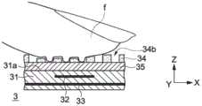
如图2A到2C所示,电容元件11具有其上形成输入操作单元14的第一表面11a、X电极12、以及Y电极13。X电极12被布置得比Y电极13更靠近第一表面11a(在Z轴方向的上侧)。As shown in FIGS. 2A to 2C , the
电容元件11具有多个基材的叠层结构,多个基材包括形成X电极12的基板和形成Y电极13的基板。形成基材的材料的例子包括PET(聚对苯二甲酸乙二醇酯)、PEN(聚萘二甲酸乙二醇酯)、PI(聚酰亚胺)、PC(聚碳酸酯)等构成的塑料材料。The
输入操作单元14由均匀厚度的片材形成并被弯折以具有预定的图案。输入操作单元14具有位于电容元件11的第一表面11a的相反侧的第二表面并接收手指f的操作。输入操作单元14的第二表面由凹部14b和凸部14c组成。凹部14b均相对于突出部14c形成高度差(difference in level),在Z轴方向上朝向电容元件11形成该高度差。The
形成输入操作单元14的凹部14b的部分与电容元件11的第一表面11a接触。同时,形成输入操作元件14的凸部14c的部分中的每一个均在电容元件11的第一表面11a与每个凸部14c之间形成空间14a。The portion forming the
输入操作单元14由即使当接收到手指f操作时仍不轻易变形的绝缘材料形成。这种材料的例子包括聚对苯二甲酸乙二醇酯、硅树脂、聚乙烯、聚丙烯、压克力(acrylic)、聚碳酸酯和橡胶材料。输入操作单元14由例如膜、模塑体、或由上述材料制成的织物形成。The
图2B示出了输入操作单元14接收到手指f的触摸操作的触摸状态(第一状态)。在触摸状态中,手指f在输入操作单元14上并不充分地用力。应注意触摸状态包括手指f在输入操作单元14上用少量的力的状态以及手指f接近输入操作单元14的状态。由于作为导体的手指f的影响,在图2B所示的触摸状态中的电容元件11的电容被减少为低于在图2A中所示的手指f没有影响的状态下的电容元件11的电容。FIG. 2B shows a touch state (first state) in which the
图2C示出了输入操作单元14接收到手指f按压操作的按压状态(第二状态)。在图2C所示的按压状态中,手指f在Z轴方向从图2B所示的触摸状态按压向输入操作单元14,并在之后变形以进入凹部14b。具体地,在按压状态中的手指f比在触摸状态中更接近于电容元件11。因此,图2C中所示的在按压状态下的电容元件11的电容进一步减少得比图2B所示的触摸状态下的电容元件11的电容更低。FIG. 2C shows a pressing state (second state) in which the
应注意输入装置1可具有能够在第一模式和第二模式之间切换的配置,在第一模式中输入装置1在触摸状态操作而并不在按压状态下操作,而在第二模式中输入装置1在按压状态下操作而并不在触摸状态下操作。在这种情况中,例如,用于改变第一模式和第二模式的选择器开关可被设置在输入装置1或处理装置p。It should be noted that the
(输入操作单元)(input operation unit)
当触摸状态变为按压状态时电容变化量取决于Z轴方向上手指f进入凹部14b的深度。为了判定单元c1(见图3)判定按压状态或触摸状态,电容变化量必须足够大。因此,在Z轴方向上相对于凸部14c的凹部14b的深度最好等于或大于预定深度。另一方面,考虑到对于输入装置1的薄化的要求,最好在Z轴方向上相对于凸部14c的凹部14b的深度不超过1mm。在本实施方式中,Z轴方向上相对于凸部14c的凹部14b的深度被设为100μm到300μm的范围。进一步地,凸部14c之间的间隔(在X轴方向和Y轴方向上的各个凸部14b的长度)最好约10倍于Z轴方向上相对于凹部14c的凸部14b的深度。The amount of capacitance change when the touch state is changed to the pressing state depends on the depth of the finger f entering the
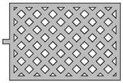
除了图2A到2C所示的凸部14c以规则间隔连续形成凹凸形以外,输入操作单元14的形状还可以是任何其他凹凸形。例如,输入操作单元14的形状可以是图4A所示的凸部间隔在X轴方向上不同的凹凸形、图4B所示的各个凸部具有向凹部底部膨胀的锥形的凹凸形、图4C所示的凸部的高度不同的凹凸形、图4D所示的凸部由弯曲表面形成的凹凸形、图4E所示形成多级凸部的凹凸形中的任意一个。The shape of the
在输入操作单元14的X-Y平面上的凹凸图案不限于如图1所示的其中布置立方体的图案,而可以是任意其他图案。例如,图5A到5J中所示的其中黑色部分对应凸部、白色部分对应凹部的形状中的每一个可用作形成包括这样的形状连续布置的图案的单元。The concavo-convex pattern on the X-Y plane of the
具体地,上述的形状可以是图5A所示包括矩形壁部和形成在壁部内四个角处的四个柱形部的形状、图5B所示的包括矩形第一壁部和内部的沿第一壁部的相对的两侧形成的两个第二壁部的形状、图5C所示的其中图5B的在纵向方向延伸的第二壁部的两端与第一壁部连续的形状。进一步地,上述的形状可以是图5D所示的多个孔被形成在矩形块部中的形状,图5E所示的多个多角形凹部被形成于矩形块部内的形状。此外,上述的形状可以是如图5F所示包括彼此以规则间隔平行形成的壁部的形状,图5G所示的包括以规则间隔形成的柱形部的形状。另外,上述的形状可以是图5H所示包括浮雕字符的形状、图5I所示的包括平坦壁部的形状、以及如图5J所示的包括多角形壁部的形状。Specifically, the above-mentioned shape may be the shape shown in FIG. 5A including a rectangular wall portion and four cylindrical portions formed at four corners of the wall portion, the shape shown in FIG. 5B including a rectangular first wall portion and an inner part along the first A shape of two second wall portions formed on opposite sides of one wall portion, a shape shown in FIG. 5C in which both ends of the second wall portion extending in the longitudinal direction of FIG. 5B are continuous with the first wall portion. Further, the above-mentioned shape may be a shape in which a plurality of holes shown in FIG. 5D are formed in a rectangular block portion, and a plurality of polygonal concave portions shown in FIG. 5E are formed in a rectangular block portion. Further, the above-mentioned shape may be a shape including wall portions formed in parallel with each other at regular intervals as shown in FIG. 5F , and a shape including columnar portions formed at regular intervals as shown in FIG. 5G . In addition, the above-mentioned shape may be a shape including embossed characters as shown in FIG. 5H , a shape including a flat wall portion as shown in FIG. 5I , and a shape including a polygonal wall portion as shown in FIG. 5J .
输入操作单元14可具有上述图案的凸部和凹部相反的形状。The
(制造输入操作单元的方法)(Method of Manufacturing Input Operation Unit)
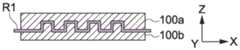
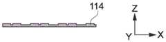
图6A到6C是示出根据本实施方式制造输入装置1的输入操作单元14的方法的图。如图6A所示,首先准备好形成输入操作单元14的片状的树脂R1。如图6B所示,树脂R1被内置在具有预定凹入图案的上模100a和具有与上模100a啮合的凸出图案的下模100b之间,以便树脂R1在加热的状态下冲压成型。之后,如图6C所示,从上模100a和下模100b中释放出树脂R1以获得输入操作单元14。6A to 6C are diagrams showing a method of manufacturing the
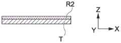
图7A到7C是示出制造输入操作单元的方法的变形例的图。如图7A所示,UV(紫外线)树脂R2首先被放置在透明板T上。固体片材或液体UV固化材料可用作树脂R2。如图7B所示,使用具有预定的凹凸图案的辊型模具101,模具101的凹凸图案被转印到UV树脂R2,从透明板T侧对UV树脂R2进行UV照射以固化。如图7C所示,将UV树脂R2从透明板T分离以得到输入操作单元114。7A to 7C are diagrams showing a modification of the method of manufacturing the input operation unit. As shown in FIG. 7A , a UV (ultraviolet) resin R2 is first placed on the transparent plate T. As shown in FIG. Solid sheet or liquid UV curable material can be used as resin R2. As shown in FIG. 7B , using a
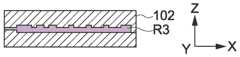
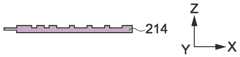
图8A到8C还是示出制造输入操作单元方法的变形例的图。如图8A所示,首先准备好具有预定形状的注射成型模102。如图8B所示,将熔化状态下的热塑性树脂R3从注入端口102a注入模102,从而进行树脂R3的注射成型。如图8C所示,使树脂R3从注射成型模102脱模以获得输入操作单元214。8A to 8C are also diagrams showing a modification of the method of manufacturing the input operation unit. As shown in FIG. 8A, an injection molding die 102 having a predetermined shape is prepared first. As shown in FIG. 8B , the thermoplastic resin R3 in a molten state is injected into the
(电容元件的电极的配置)(Arrangement of Electrodes of Capacitance Element)
图9是从Z轴方向看的输入装置1的平面图,仅示出了电容元件11中的X电极12和Y电极13。X电极12和Y电极13以所谓交叉矩阵形式形成。输入装置1包括在输入装置1的Y轴方向上的整个范围上延伸的n列X电极12和在输入装置1的X轴方向上的整个范围上延伸的m行Y电极13。X电极12被布置在输入装置1的X轴方向上的整个范围上,Y电极13被布置在输入装置1的Y轴方向上的整个范围上。应注意电极可不一定以规则间隔布置,布置上的间距可根据相应的按键位置进行改变。FIG. 9 is a plan view of the
在输入装置1中,图2A到图2C中示出的电容元件11被形成在X电极12和Y电极13彼此交叉的位置处。因此,输入装置1包括n*m个电容元件11。在输入装置分别包括具有相同面积的输入操作单元14的情况中,具有更大的n和m值的输入装置在X-Y平面上具有更高密度的电容元件11,并因此可更准确地检测操作位置。In the
应注意,根据本实施方式的输入装置1采用互电容系统,但在并不同时在多个位置对输入操作单元14进行操作的单触摸系统的情况下,而不是在多触摸系统的情况中,可采用自电容系统。It should be noted that the
图10是示出采用自电容系统的情况的电极配置的图。X电极12a和Y电极13a是被布置为在Z轴上互不重叠的菱形电极。X电极12a形成在Y轴方向上延伸的n列,Y电极13a形成在X轴方向上延伸的m行。应注意在对于输入装置1采用自电容系统的情况中,图2B所示的触摸状态中的电容元件11的电容高于在图2A中所示的状态中的电容元件11的电容,在图2C所示的按压状态中的电容元件11的电容高于在图2B中所示的触摸状态中的电容元件11的电容。FIG. 10 is a diagram showing an electrode configuration in a case where a self-capacitance system is employed. The
(控制器)(controller)
控制器c一般包括CPU(中央处理单元)或MPU(微处理单元)。在本实施方式中,控制器c包括判定单元c1和信号生成单元c2,并根据存储在存储器中的程序(未示出)执行多种功能。判定单元c1基于输出自电容元件11的电信号判定输入操作单元14的状态。信号生成单元c2基于判定单元c1的判定结果生成操作信号。进一步地,控制器c包括用于驱动输入装置1的驱动电路。驱动电路以预定的时间间隔输出驱动信号至电容元件11中的每一个。控制器c还包括输出判定电路,该输出判定电路处理来自电容元件11中每一个元件关于驱动信号的输出,并判定来自用户所操作的输入装置1的输入操作。The controller c generally includes a CPU (Central Processing Unit) or an MPU (Micro Processing Unit). In the present embodiment, the controller c includes a determination unit c1 and a signal generation unit c2, and executes various functions according to a program (not shown) stored in a memory. The determination unit c1 determines the state of the
图11是示出来自电容元件11的输出信号的示例的图。沿图11的X轴示出的条(bar)分别代表基于由每个X电极12形成的任意电容元件11的参考电容的电容变化量。沿图11的Y轴示出的条分别代表基于由每个Y电极13形成的电容性电极11的参考电容的电容变化量。这里,参考电容指图2A所示状态中电容元件11的电容,该电容不受手指f的影响。条被分为图2B所示的触摸状态(由“T”标示)和图2C所示的按压状态(由“P”标示)。FIG. 11 is a diagram showing an example of an output signal from the
图3所示的控制器c的判定单元c1基于从X电极12和Y电极13获得的电容变化量计算手指f在输入操作单元14上的操作位置在X轴方向和Y轴方向的坐标。具体地,在图11中,判定单元c1基于由X电极12(X1、X2、X3、X4)形成的电容元件11的电容变化量的比率计算手指f的操作位置的X坐标,并基于由Y电极13(Y1、Y2、Y3、Y4)形成的电容元件11的电容变化量的比率计算手指f的操作位置的Y坐标。因此,判定单元c1向信号生成单元c2输出在输入操作单元14的操作位置的坐标(见图3)。The determination unit c1 of the controller c shown in FIG. 3 calculates the coordinates in the X-axis direction and the Y-axis direction of the operation position of the finger f on the
判定单元c1可使用由X电极12或Y电极13形成的电容元件11的电容变化量的最大值作为指示图2B所示的触摸状态或如2C所示的按压状态的评价值。The determination unit c1 may use the maximum value of the capacitance change amount of the
进一步地,判定单元c1可使用由X电极12形成的电容元件11的电容变化量的组合值(下文中,被称为X组合值,该值是图11中沿X轴所示的各个条的值的组合值(combinedvalue))。代替X组合值,判定单元c1可使用由Y电极13形成的电容元件11的电容变化量的组合值(下文中,被称为Y组合值,该值是图11中沿Y轴所示的各个条的值的组合值)。可选地,代替X组合值或Y组合值,判定单元c1可使用通过进一步组合X组合值和Y组合值而获得的值。Further, the determination unit c1 may use a combined value of the capacitance change amount of the
具体地,在判定单元c1中设置第一阈值和大于第一阈值的第二阈值。当评价值等于或大于第一阈值并小于第二阈值时判定单元c1判定为触摸状态,当评价值等于或大于第二阈值时判定单元c1判定为按压状态。之后,判定单元c1向信号生成单元c2输出判定结果(见图3)。Specifically, a first threshold value and a second threshold value larger than the first threshold value are set in the determination unit c1. The determination unit c1 determines the touch state when the evaluation value is equal to or greater than the first threshold and less than the second threshold, and determines the press state when the evaluation value is equal to or greater than the second threshold. After that, the determination unit c1 outputs the determination result to the signal generation unit c2 (see FIG. 3 ).
在判定单元c1中可对第一阈值和第二阈值设定任何值。例如,第一阈值和第二阈值对于诸如女性和儿童这样手指力量弱的用户可设为小值,或对于手指力量强的用户可设为大值。在大手指用户情况中,与输入操作单元14接触的手指面积比小手指用户大。在这种情况中,在触摸状态和按压状态中增加了电容元件11的电容变化量。因此,对于大手指用户,可设定大的第一阈值和第二阈值。Any value can be set for the first threshold value and the second threshold value in the determination unit c1. For example, the first threshold and the second threshold may be set to small values for users with weak finger strength such as women and children, or may be set to large values for users with strong finger strength. In the case of a large-fingered user, the area of the finger in contact with the
附带地,判定单元c1以预定的时间段Ts(一般,15毫秒或20毫秒)的间隔读取电容元件11的电容变化量。在手指f在输入操作单元14上的操作以Ts以上的预定的时间段继续的情况中,判定单元c1可以读取准确的电容变化量。另一方面,对于读取手指f在输入操作单元14上短时间操作,判定单元c1难以读取准确的电容变化量。Incidentally, the determination unit c1 reads the capacitance change amount of the
特别地,在输入装置1用作个人计算机键盘的情况中,轻放在输入操作单元14上的手指f按压进与输入操作单元14的按键对应的部分。因此,如果判定单元c1难以准确地判定触摸状态或按压状态,将经常出现打字错误。此外,用于个人计算机的键盘最好能够每秒输入10个字符。因此,为了读取准确的电容变化量,判定单元c1的读取速度是不够的。In particular, in the case where the
图12是示出手指f和电容元件11之间的距离d的时间变化(图12的上部)和由判定单元c1读取的电容元件11的电容变化量的值δ的时间变化(图12的下部)的曲线图。时间轴t在图12的两个部分中是共同的。图12的垂直实线之间的间隔对应上述的判定单元c1读取电容变化量的时间间隔。进一步地,图12的下部中,上面提到的电容变化量的第二阈值由虚线示出。FIG. 12 is a graph showing the time change of the distance d between the finger f and the capacitive element 11 (the upper part of FIG. 12 ) and the time change of the value δ of the capacitance change amount of the
在图12的上部,形成两个波谷,输入装置1在图12所示的时间段中两次被置于按压状态。判定单元c1检测到读取值δ超过第二阈值的第一个按压状态。另一方面,在第二个按压状态中,实际电容变化量的最大值超过第二阈值,但在判定单元c1中的电容变化量的读取值δ并未超过第二阈值。这是因为手指f在输入操作单元14上进行了短时操作,电容变化量在判定单元c1读取电容变化量的两个计时(彼此相邻的垂直实线)之间达到最大。In the upper part of FIG. 12 , two valleys are formed, and the
为了防止判定单元c1在这种状态下判定触摸状态或按压状态失败,判定单元c1基于连续获得的电容变化量的两个读取值δ计算电容变化速度V。In order to prevent the determination unit c1 from failing to determine the touch state or the pressed state in this state, the determination unit c1 calculates the capacitance change speed V based on the two read values δ of the capacitance change amount obtained continuously.
判定单元c1通过下面的表达式计算电容变化速度V,该表达式使用例如电容变化量的读取值δ中连续的第N次和第N+1次的读取值δ(N)和读取值δ(N+1)、以及上面提到的预定的时间段Ts。The determination unit c1 calculates the capacitance change speed V by the following expression using, for example, the read value δ(N) and the read value δ(N) of the Nth and N+1th consecutive read values δ of the capacitance change amount. The value δ(N+1), and the predetermined time period Ts mentioned above.
V=[δ(N+1)-δ(N)]/TsV=[δ(N+1)-δ(N)]/Ts
对于判定单元c1,设定第三阈值和大于第三阈值的第四阈值。判定单元c1在电容变化速度V等于或大于第三阈值并小于第四阈值时判定触摸状态,并且在电容变化速度V等于或大于第四阈值时判定按压状态。For the determination unit c1, a third threshold value and a fourth threshold value larger than the third threshold value are set. The determination unit c1 determines the touch state when the capacitance change speed V is equal to or greater than the third threshold value and less than the fourth threshold value, and determines the pressed state when the capacitance change speed V is equal to or greater than the fourth threshold value.
用这样的配置,在输入装置1中,当手指f在输入操作单元14上进行短时操作时也可精确地判定触摸状态或按压状态。像第一阈值和第二阈值的情况那样,在判定单元c1中可设定任意值作为第三阈值和第四阈值。With such a configuration, in the
以这种方式,在根据本实施方式的输入装置1中,判定单元c1可准确地判定触摸状态或按压状态。In this way, in the
根据来自判定单元c1的输出信号,信号生成单元c2生成操作信号。具体地,信号生成单元c2生成在触摸状态和按压状态之间不同的操作信号。Based on the output signal from the determination unit c1, the signal generation unit c2 generates an operation signal. Specifically, the signal generating unit c2 generates operation signals that differ between the touch state and the pressing state.
如上所述,根据本实施方式的输入装置1没有机械结构,因此具有长的使用寿命和良好的防水性。As described above, the
(电子设备)(Electronic equipment)
(个人计算机)(Personal computer)
将描述根据本实施方式的输入装置1被应用至个人计算机的示例。图13是输入装置1的俯视图。在输入操作单元14上以与通常使用的个人计算机的键盘的按键相似的按键布置画出字符或图案。An example in which the
在此示例中,图9所示的电极的配置可被改变为图14的电极配置。在图14所示的电极配置中,X电极12b和Y电极13b被布置为使电容元件11对应各个按键。用这种配置,判定单元c1精确地判定所操作的按键的位置。In this example, the configuration of the electrodes shown in FIG. 9 may be changed to the electrode configuration of FIG. 14 . In the electrode configuration shown in FIG. 14, the
图15到图18是分别示出包括根据本实施方式的输入装置1和作为输出装置o的显示装置o1(见图3)的作为电子设备z(见图3)的个人计算机z1配置的示意图。个人计算机z1包括处理装置p(未示出)(见图3)。15 to 18 are schematic diagrams respectively showing the configuration of a personal computer z1 as an electronic device z (see FIG. 3 ) including an
在桌面型个人计算机z1的情况中,输入装置1被配置为独立于作为处理装置p的主体和显示装置o1。主体和显示装置o1可被整体或单独配置。此外,输入装置1可通过电缆或无线电波连接至主体和显示装置o1。In the case of the desktop personal computer z1, the
另一方面,在笔记本型个人计算机z1的情况中,输入装置1、处理装置p、以及显示装置o1可被整体配置。在这种情况中,输入装置1的控制器c还可作为处理装置p。On the other hand, in the case of the notebook-type personal computer z1, the
将对图15进行描述。当用手指进行向对应输入操作单元14的各个按键的X轴(第一轴)坐标和Y轴(第二轴)坐标位置施加按压力的按压操作时,输入装置1的判定单元c1判定该按键的位置被置于按压状态并向输入装置1的信号生成单元c2输出判定结果。因此,信号生成单元c2对应被置于按压状态位置处的按键的字符或图案生成用于显示的操作信号,并输出操作信号至处理装置p。处理装置p基于操作信号生成命令信号,显示装置o1基于命令信号显示图像。这样,可以与通用个人计算机的键盘相似地使用输入装置1。FIG. 15 will be described. The determination unit c1 of the
下面,将对图16进行描述。当用与输入操作单元14接触的手指f进行在输入操作单元14上移动的触摸操作时,输入装置1的判定单元c1判定对应手指f移动轨迹的位置被置于触摸状态,并向输入装置1的信号生成单元c2输出判定结果。因此,信号生成单元c2基于手指f的移动轨迹生成用于移动指针p的操作信号,并向处理装置p输出操作信号。处理装置p基于操作信号生成命令信号,显示装置o1基于命令信号移动指针p。这样,在输入装置1中,指针可如用于通用个人计算机的鼠标或触控板的情况中那样被直观地移动。Next, FIG. 16 will be described. When a touch operation of moving on the
此外,当输入操作单元14接收到在显示装置o1中指针p在图标(未示出)上的状态中按压操作时,输入装置1的判定单元c1判定输入操作14被置于按压状态,并向输入装置1的信号生成单元c2输出判定结果。因此,信号生成单元c2生成操作信号,用该操作信号,图标被置于被选择状态,并向处理装置p输出操作信号。处理装置p基于操作信号生成命令信号,显示装置o1基于命令信号将图标置于被选状态。以这种方式,输入装置1具有对应用于通用个人计算机的鼠标或触控板的点击或轻拍的功能。Further, when the
此外,当输入操作单元14在显示装置o1中指针p在图标上的状态中连续两次接收到按压操作,输入装置1的判定单元c1判定输入操作14连续两次被置于短时间按压状态,并向输入装置1的信号生成单元c2输出判定结果。因此,信号生成单元c2生成用于打开图标的操作信号,并向处理装置p输出操作信号,处理装置p基于操作信号生成命令信号,显示装置o1基于命令信号打开图标。以这种方式,输入装置1具有对应用于通用个人计算机的鼠标或触控屏的双击或双轻拍的功能。Further, when the
接着,将对图17进行描述。当用与输入操作单元14接触的手指f做出在短时间内在输入操作单元14上快速移动的触摸操作(也被称为“划动操作(swipe operation)”或“拂动操作(flick operation)”)时,输入装置1的判定单元c1检测触摸状态下的操作位置的移动方向并输出检测结果至输入装置1的信号生成单元c2。因此,信号生成单元c2基于操作位置的移动方向生成用于移动图像的操作信号,并向处理装置p输出操作信号。处理装置p基于操作信号生成命令信号,显示装置o1基于命令信号移动图像。此外,输入装置1可通过相似的操作进行显示在显示装置o1上的电子书的翻页的操作。此外,输入装置1还可以通过相似的操作进行将显示在显示装置o1上的屏幕改变为另一屏幕的操作。Next, FIG. 17 will be described. When a touch operation (also referred to as a "swipe operation" or a "flick operation") of rapidly moving on the
接着,将对图18进行描述。当在输入操作单元14上做出将与输入操作单元14接触的两个手指f彼此分开的触摸操作(也称为“扩大操作(pinch-out operation)”),输入装置1的判定单元c1检测到触摸状态下的操作位置彼此分开移动并输出检测结果至输入装置1的信号生成单元c2。因此,信号生成单元c2生成用于放大图像的操作信号,并向处理装置p输出操作信号。处理装置p基于操作信号生成命令信号,显示装置o1基于命令信号放大图像。Next, FIG. 18 will be described. When a touch operation (also referred to as a "pinch-out operation") for separating two fingers f in contact with the
相似地,当在输入操作单元14上做出将与输入操作单元14接触的两个手指f靠近的触摸操作(也被称为“收拢操作”),输入装置1的判定单元c1检测到触摸状态下的操作位置彼此接近移动,并输出检测结果至输入装置1的信号生成单元c2。因此,信号生成单元c2生成用于缩小图像的操作信号,并向处理装置p输出操作信号。处理装置p基于操作信号生成命令信号,显示装置o1基于命令信号缩小图像。Similarly, when a touch operation (also referred to as a "pinch operation") of bringing two fingers f in contact with the
如上所述,根据本实施方式的输入装置1具有个人计算机z1中的键盘的功能和指针装置(pointing device)的功能。输入装置1可被配置能在用作键盘的模式和用作指针装置的模式之间切换。在这种情况中,例如,模式选择器开关可被设置于输入装置1或处理装置p。As described above, the
在上文中,已描述了个人计算机z1中的输入装置1的功能示例。但输入装置1可实现诸如键盘、鼠标、触控板以及触摸屏这样的通用输入装置的任何功能。例如,显示在显示装置o1上的文档或浏览器可通过类似于上述的通用输入装置中进行的操作被滚动翻页。In the above, the functional example of the
(便携终端设备)(Portable Terminal Equipment)
将对根据本实施方式的输入装置1应用于便携终端设备的示例进行描述。An example in which the
图19A和图19B是分别示出包括根据本实施方式的输入装置1和作为输出装置o(见图3)的显示装置o2的作为电子设备z(见图3)的便携终端设备z2的配置的示意图。便携终端设备z2可包括处理装置p(未示出)(见图3)。输入装置1的控制器c还可作为处理装置p,或显示装置o2可包括处理装置p。FIGS. 19A and 19B are diagrams showing the configuration of a portable terminal device z2 as an electronic device z (see FIG. 3 ) including an
以类似于通用便携终端设备的按键布置在输入操作单元14上画出字符或图案。输入装置1和显示装置o2可被整体配置或独立配置。此外,便携终端装置z2可被配置为可折叠的以使输入装置1的输入操作单元14和显示装置o2的显示屏幕彼此靠近。Characters or patterns are drawn on the
将对图19A给出描述。当用手指进行向对应于输入操作单元14的各个按键的位置施加按压力的按压操作时,输入装置1的判定单元c1判定按键的位置被置于按压状态并向输入装置1的信号生成单元c2输出判定结果。因此,信号生成单元c2对应被置于按压状态位置处的按键的字符或图案生成用于显示的操作信号,并输出操作信号至处理装置p。处理装置p基于操作信号生成命令信号,显示装置o2基于命令信号显示图像。以这种方式,可以与通用便携终端设备的数字键区相似地使用输入装置1。A description will be given to Fig. 19A. When a pressing operation that applies a pressing force to the position of each key corresponding to the
下面,将对图19B给出描述。当用与输入操作单元14接触的手指f进行在输入操作单元14上移动的触摸操作时,输入装置1的判定单元c1判定对应手指f移动轨迹的位置被置于触摸状态,并向输入装置1的信号生成单元c2输出判定结果。因此,信号生成单元c2基于手指f的移动轨迹生成用于移动指针p的操作信号,并向处理装置p输出操作信号。处理装置p基于操作信号生成命令信号,显示装置o2基于命令信号移动指针p。以这种方式,在输入装置1中,指针可被直观地移动。Next, a description will be given to FIG. 19B. When a touch operation of moving on the
在上文中,已描述了便携终端设备z2中的输入装置1的功能示例,但输入装置1可实现诸如数字键区和触摸面板这样的通用输入装置的任何功能。例如,显示在显示装置o2上的文档或浏览器可通过类似于上述的通用输入装置中进行的操作而滚动翻页。In the above, an example of the function of the
(成像设备)(imaging equipment)
将对根据本实施方式的输入装置1应用于成像设备的示例给出描述。A description will be given of an example in which the
图20是示出包括根据本实施方式的输入装置1和透镜z3a的作为电子设备z(见图3)的成像设备z3的配置的示意图。成像设备z3包括作为输出装置o(见图3)的成像机构(未示出)和被配置为存储所拍摄的图像的记录单元。输入装置1是包括单电容元件11的快门装置。成像设备z3可包括处理装置p(未示出)(见图3)。输入装置1的控制器c还可作为处理装置p。因此,图9中所示的n和m的值是1,图11所示的示例中判定单元c1的评价值仅是1。FIG. 20 is a schematic diagram showing the configuration of an imaging device z3 as an electronic device z (see FIG. 3 ) including the
当手指f进行触摸输入操作单元14的触摸操作,输入装置1的判定单元c1判定状态被置于触摸状态,并向输入装置1的信号生成单元c2输出判定结果。因此,信号生成单元c2生成的用于将成像机构置于快门按钮被压下一半的状态的操作信号,并输出操作信号至处理装置p。处理装置p基于操作信号生成命令信号以使成像机构基于命令信号被置于快门按钮压下一半的状态,透镜z3a所获得的图像被聚焦。When the finger f performs the touch operation of the touch
当向手指进行输入操作单元14施加按压力的按压操作,输入装置1的判定单元c1判定状态被置于按压状态,并输出判定结果至输入装置1的信号生成单元c2。因此,信号生成单元c2生成用于将成像机构置于快门按钮被压入的状态的操作信号,并输出操作信号至处理装置p。处理装置p基于操作信号生成命令信号以使成像机构基于命令信号被置于快门按钮压入的状态,透镜z3a所获得的图像被记录在记录单元中。When a pressing operation of applying a pressing force to the
(便携音乐播放器)(Portable Music Player)
将对根据本实施方式的输入装置1应用于便携音乐播放器的示例给出描述。A description will be given of an example in which the
图21A和图21B是分别示出作为电子设备z(见图3)的便携音乐播放器z4的配置的示意图。便携音乐播放器z4包括根据本实施方式的输入装置1和被配置为存储音频数据的记录单元(未示出)。便携音乐播放器z4可包括处理装置p(未示出)(见图3)。输入装置1的控制器c还可作为处理装置p。作为输出装置o(见图3)的耳机被连接至便携音乐播放器z4。输出装置o不限于耳机,而可以是听筒、扬声器等。以类似于通用便携音乐播放器的按键布置在输入操作单元14上画出图案。21A and 21B are schematic diagrams respectively showing the configuration of the portable music player z4 as the electronic device z (see FIG. 3 ). The portable music player z4 includes the
将对图21A给出描述。当用手指f进行向对应于输入操作单元14的各个按键的位置施加按压力的按压操作时,输入装置1的判定单元c1判定按键位置被置于按压状态并向输入装置1的信号生成单元c2输出判定结果。因此,信号生成单元c2对应被置于按压状态位置处的按键的字符或图案生成用于进行操作(例如,“重放”或“快进”)的操作信号,并输出操作信号至处理装置p。处理装置p基于操作信号生成命令信号,耳机基于命令信号输出音频数据。A description will be given to Fig. 21A. When a pressing operation to apply a pressing force to the position corresponding to each key of the
接着,将对图21B进行描述。当与输入操作单元14接触的手指f在X轴(第一轴)方向向右作出在输入操作单元14上短时间内快速移动的触摸操作时,输入装置1的判定单元c1检测触摸状态下的操作位置的移动方向并向输入装置1的信号生成单元c2输出检测结果。因此,信号生成单元c2基于操作位置的移动方向生成用于增加音量的操作信号,并输出操作信号至处理装置p。处理装置p基于操作信号生成命令信号,耳机基于命令信号增加输出的音频数据的音量。Next, FIG. 21B will be described. When the finger f in contact with the
相反地,当与输入操作单元14接触的手指f在X轴(第一轴)方向向左作出在输入操作单元14上短时间内快速移动的触摸操作时,输入装置1的判定单元c1检测触摸状态下的操作位置的移动方向并向输入装置1的信号生成单元c2输出检测结果。因此,信号生成单元c2基于操作位置的移动方向生成用于减少音量的操作信号,并输出操作信号至处理装置p。处理装置p基于操作信号生成命令信号,耳机基于命令信号减少输出的音频数据的音量。Conversely, when the finger f in contact with the
(远程控制器)(remote controller)
将对根据本实施方式的输入装置1应用于远程控制器的示例给出描述。A description will be given of an example in which the
图22A和图22B是分别示出作为根据本实施方式的输入装置1的远程控制器z5配置的示意图。远程控制器z5包括传输单元z5a。远程控制器z5被配置为作为电子设备z(见图3)的例如电视机、游戏机、或DVD(数字多功能光盘)播放器的一部分。这里,电视机将作为示例被描述。电视机包括处理装置p(见图3)和作为输出装置o(见图3)的显示装置。以类似于用于通用电视机的远程控制器的按键布置在远程控制器z5的输入操作单元14上画出文字或图案。22A and 22B are schematic diagrams each showing the configuration of the remote controller z5 as the
将对图22A给出描述。当用手指f进行向对应于输入操作单元14的各个按键(key)的位置施加按压力的按压操作时,输入装置1的判定单元c1判定按键的位置被置于按压状态并向输入装置1的信号生成单元c2输出判定结果。因此,信号生成单元c2对应被置于按压状态位置处的按键的字符或图案生成用于进行操作(例如,“频道切换”或“显示TV节目列表”)的操作信号,并输出操作信号至处理装置p。处理装置p基于操作信号生成命令信号,显示装置基于操作信号进行显示。以这种方式,输入装置1可与用于通用电视机的远程控制器类似地使用。A description will be given to FIG. 22A. When a pressing operation of applying a pressing force to the positions corresponding to the respective keys of the
接着,将对图22B给出描述。当用与输入操作单元14接触的手指f进行在输入操作单元14上移动的触摸操作时,输入装置1的判定单元c1判定对应手指f移动轨迹的位置被置于触摸状态,并向输入装置1的信号生成单元c2输出判定结果。因此,信号生成单元c2基于手指f的移动轨迹生成用于在预设录像等时移动显示在电视机的显示装置上的指针p的操作信号,并向电视机的处理装置p输出操作信号。处理装置p基于操作信号生成命令信号,显示装置o1基于操作信号移动指针p。以这种方式,在输入装置1中,指针可被直观地移动。Next, a description will be given to FIG. 22B. When a touch operation of moving on the
(头戴显示器)(head mounted display)
将对根据本实施方式的输入装置1应用于头戴显示器(HMD)的示例给出描述。A description will be given of an example in which the
图23A到图25B是示出作为根据本实施方式的输入装置1和作为电子设备z(见图3)的HMD z6的示意图。图23A、图24A和图25A是分别示出根据本实施方式的输入装置1的俯视图。图23B、图24B和图25B是分别示出被显示在作为根据本实施方式的电子设备z(见图3)的HMD z6上的显示图像的图。HMD z6包括输入装置1和作为输出装置o(见图3)的显示装置o6。HMD z6可进一步包括处理装置p(未示出)(见图3)。输入装置1的控制器c也可作为处理装置p,或显示装置o6可包括处理装置p。23A to 25B are schematic diagrams showing the HMD z6 as the
HMD z6包括戴在用户头上的主体并被配置为经由显示装置o6的显示器d提供图像,其中显示器d被放置在眼前。HMD z6是例如非透明(non-see-through)HMD,但其可以是透明或半透明HMD。The HMD z6 includes a body worn on the user's head and is configured to provide images via a display d of the display device o6, wherein the display d is placed in front of the eyes. HMD z6 is eg a non-see-through HMD, but it can be a transparent or translucent HMD.
例如,如图23A和图23B所示,输入装置1包括预定布置的按键,该按键在输入操作单元14上具有数字,电容元件11被布置在对应各个按键(未示出)的位置处。这里,数字1到3被分配至各个按键。输入装置1可被配置为具有独立于HMD z6主体的另一框体。在这种情况中,输入装置1通过电缆或无线电波连接至HMD z6的主体。可选地,输入装置1可直接布置在HMD z6主体中。For example, as shown in FIGS. 23A and 23B , the
特别地,在本实施方式的输入装置1应用于非透明HMD z6的情况中,对于用户来说难以看见其在输入装置1上进行输入操作的手。这样,可能导致误操作。在根据本实施方式的HMD z6中,基于在输入装置1上的输入操作的图像被显示在显示装置o6的显示器上,以便即使用户难以看见手,用户也可以确认其自身的输入操作。In particular, in the case where the
将对图23A和23B给出描述。图23A示出了用户的手指不接近输入操作单元14的初始状态。图23B示出了显示器d上的初始图像。输入操作单元14被示意性地画出在初始图像上。在这种情况中,控制器c的判定单元c1既不判定触摸状态也不判定按压状态,图23B示出的初始图像不变。A description will be given to FIGS. 23A and 23B. FIG. 23A shows an initial state in which the user's finger does not approach the
将对图24A和24B给出描述。图24A示出用户的手指f在对应按键“1”的位置处的输入操作单元14上进行触摸操作。在这时,输入装置1的判定单元c1判定按键的位置被置于触摸状态,并向信号生成单元c2输出判定结果。信号生成单元c2生成指示处于触摸状态的按键位置的信息的操作信号,并输出操作信号至处理装置p。处理装置p基于操作信号生成用于控制对应显示在显示图像上的按键“1”的图像的命令信号,显示装置o6基于命令信号显示图像(图24B)。例如,处理装置p在显示器d上显示其中对应按键“1”的图像的外边缘由粗线围成的图像。该图像使得用户可以意识到按键“1”被触摸。A description will be given to FIGS. 24A and 24B. FIG. 24A shows that the user's finger f performs a touch operation on the
对图25A和25B给出描述。图25A示出了用户手指在输入操作单元14上对应按键“1”的位置处进行按压操作。在这时,输入装置1的判定单元c1判定按键的位置被置于触摸状态,并向信号生成单元c2输出判定结果。信号生成单元c2生成指示处于按压状态的按键位置的信息的操作信号,并输出操作信号至处理装置p。处理装置p基于操作信号生成用于控制对应显示在显示图像上的按键“1”的图像的命令信号,显示装置o6基于命令信号显示图像(图25B)。例如,如图25B所示,处理装置p在显示器d上改变对应按键“1”的图像的颜色,并以不同于触摸操作的形式显示显示图像。该图像使得用户可以意识到按键“1”被按压。A description is given to Figs. 25A and 25B. FIG. 25A shows that the user's finger performs a pressing operation on the
此外,除了图24和图25中示出的示例,只要触摸操作和按压操作被清楚地彼此区别,显示图像无具体限制。例如,对应按键“1”的显示在触摸状态下可以闪烁,在按压状态下显示的颜色可被改变。可选地,在触摸或按压状态中,可改变显示形式。Furthermore, other than the examples shown in FIGS. 24 and 25 , as long as the touch operation and the pressing operation are clearly distinguished from each other, the displayed image is not particularly limited. For example, the display corresponding to the key "1" may blink in the touch state, and the color of the display in the pressed state may be changed. Optionally, in the touch or press state, the display form can be changed.
如上文所述,通过应用根据本实施方式的输入装置1的作为电子设备z的HMD z6,即使用户难以看见进行输入操作的手,输入操作位置和触摸状态或按压状态可被可视化地识别。因此,利用输入装置1可进行更精确的操作。As described above, by applying the HMD z6 as the electronic device z of the
(操作元件)(operating element)
在本实施方式中,手指f被作为操作元件的例子,但任意操作元件可被使用——只要其具有导电性和弹性。例如,可使用由导电树脂材料制成的触针笔(stylus pen)作为另一操作元件。In the present embodiment, the finger f is taken as an example of the operation element, but any operation element may be used as long as it has conductivity and elasticity. For example, a stylus pen made of a conductive resin material may be used as another operating element.
(第二实施方式)(Second Embodiment)
图26A到图26C是根据本公开第二实施方式的输入装置2的局部截面图。除了根据本实施方式的输入装置2的输入操作单元24以外的其他配置与第一实施方式相同,其描述将根据需要略去。图26A到图26C对应根据第一实施方式的图2A到图2C。26A to 26C are partial cross-sectional views of the
如图26A到图26C所示,电容元件21具有其上形成输入操作单元24的第一表面21a、X电极22、和Y电极23。X电极22被布置得比Y电极23更靠近第一表面21a(在z轴方向的上侧)。As shown in FIGS. 26A to 26C , the
输入操作单元24是具有均匀厚度并当受到手指f的操作时弹性变形的片材。作为用于形成输入操作单元24的材料,具有相对高的弹性系数的材料比具有低弹性系数的材料更合适,以便在触摸操作中消除变形。这样的材料的示例包括诸如硅橡胶的橡胶材料和诸如聚氨酯和聚乙烯的泡沫材料。除此以外,例如,可使用诸如布料、牛皮、人造革的弹性变形材料。The
图26B示出了输入操作单元24受到手指f的触摸操作的触摸状态(第一状态)。在触摸状态中,手指f基本上不在输入操作单元24上施力。由于作为导体的手指f的影响,图26B所示的触摸状态中的电容元件21的电容被减少得比图26A所示的手指f没有影响的状态中的电容元件21的电容要低。FIG. 26B shows a touch state (first state) in which the
图26C示出了输入操作单元24受到手指f的按压操作的按压状态(第二状态)。在图26C所示的按压状态中,手指f在Z轴方向从图26B所示的触摸状态按压向输入操作单元24,于是输入操作单元24变形。具体地,按压状态下的手指比在触摸状态下更接近电容元件21。因此,图26C所示的触摸状态中的电容元件21的电容被进一步减少得比图26B所示的触摸状态下的电容元件21的电容要低。FIG. 26C shows a pressed state (second state) in which the
图27A和图27B分别示出了由泡沫材料制成的输入操作单元24的触摸状态和按压状态。在触摸状态中,空气孔24a具有圆形截面并具有相对大的分散间隔。在按压状态中,空气孔24a具有在Z轴方向上被压缩的形式,并具有相对小的分散间隔。27A and 27B respectively show the touch state and the pressed state of the
应注意在本实施方式中,输入操作单元24具有均匀厚度,但输入操作单元24可被设置为具有如根据第一实施方式的输入操作单元14情况中那样的凹凸形。在这种情况中,在按压状态下,不仅输入操作单元24本身,而且手指f被弹性变形,且手指f进入形成在输入操作单元24中的凹部。It should be noted that in the present embodiment, the
此外,在本实施方式中,手指被作为操作元件的例子,但只要其具有导电性,可使用任意操作元件。作为另一操作元件,例如,可使用由金属材料制成的触针笔。In addition, in the present embodiment, a finger is used as an example of the operation element, but any operation element may be used as long as it has conductivity. As another operating element, for example, a stylus pen made of a metallic material can be used.
(第三实施方式)(third embodiment)
图28A到图28C是根据本公开第三实施方式的输入装置3的局部截面图。除了根据本实施方式的输入装置3的输入操作单元34以外的其他配置与第一实施方式相同,根据需要省略其描述。图28A到图28C对应根据第一实施方式的图2A到图2C。28A to 28C are partial cross-sectional views of the
如图28A到图28C所示,电容元件31具有其上形成输入操作单元34的第一表面31a、X电极32和Y电极33。X电极32被布置得比Y电极33更靠近第一表面31a(在z轴方向的上侧)。As shown in FIGS. 28A to 28C , the
板35被形成在电容元件31和输入操作单元34之间。换句话说,板35被形成在电容元件31的第一表面31a上,输入操作单元34被形成在板35上。板35由即使当受到手指f操作时也不易于变形的绝缘材料形成。这样的材料的示例包括聚对苯二甲酸乙二醇酯、硅树脂、聚乙烯、聚丙烯、亚克力、聚碳酸酯和橡胶材料。可使用膜、模塑体或由上述材料制成的织物形成板35。A
输入操作单元34包括板35上以规则间隔布置的并当受到手指f的操作时弹性变形的凸起。输入操作单元34如根据第二实施方式的输入操作单元34的情况那样由硅橡胶等形成。The
图28B示出了输入操作单元34受到手指f的触摸操作的触摸状态(第一状态)。在触摸状态中,手指f基本上不在输入操作单元34上施力。由于作为导体的手指f的影响,图28B所示的触摸状态中的电容元件31的电容减少得比图28A所示的手指f没有影响的状态中的电容元件31的电容要低。FIG. 28B shows a touch state (first state) in which the
图28C示出了输入操作单元34受到手指f的按压操作的按压状态(第二状态)。在图28C所示的按压状态中,手指f在Z轴方向从图28B所示的触摸状态按压向输入操作单元34,输入操作单元34在Z轴方向上弹性变形,同时,手指f变形进入形成在输入操作单元34凸起之间的凹部34b。具体地,按压状态下的手指f比在触摸状态下更靠近电容元件31。因此,图28C所示的触摸状态中的电容元件31的电容被进一步减少得比图28B所示的触摸状态下的电容元件31的电容要低。FIG. 28C shows a pressed state (second state) in which the
此外,在本实施方式中,手指被作为操作元件的例子,但只要其具有导电性,可使用任意操作元件。例如,可使用由金属材料制成的触针笔作为另一操作元件。In addition, in the present embodiment, a finger is used as an example of the operation element, but any operation element may be used as long as it has conductivity. For example, a stylus pen made of a metallic material can be used as another operating element.
(第四实施方式)(Fourth Embodiment)
图29A到图29C是根据本公开第四实施方式的输入装置4的局部截面图。除了根据本实施方式的输入装置4的输入操作单元44以外的其他配置与第一实施方式相同,将根据需要省略其描述。图29A到图29C对应根据第一实施方式的图2A到图2C。29A to 29C are partial cross-sectional views of the
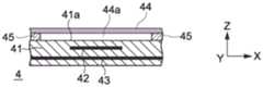
如图29A到图29C所示,电容元件41具有其上形成输入操作单元44的第一表面41a、X电极42和Y电极43。X电极42被布置得比Y电极43更靠近第一表面41a(在z轴方向的上侧)。As shown in FIGS. 29A to 29C , the
支持部45设置在电容元件41的第一表面41a上以包围X电极42和Y电极43交叉的位置。支持部45由即使受到手指f的操作也不易于变形的绝缘材料形成。这样的材料的例子包括聚对苯二甲酸乙二醇酯、硅树脂、聚乙烯、聚丙烯、亚克力、聚碳酸酯和橡胶材料。例如,可使用膜、模塑体、或由上述材料制成的织物形成板45。The
输入操作单元44是具有均匀厚度并当受到手指f的操作时弹性变形的片材。输入操作单元44由支持部45支持。因此,在输入操作单元44和电容元件41之间形成空间44a。片材、即输入操作单元44如根据第二实施方式的输入操作单元24情况那样地由硅橡胶等形成。The
支持部45用于在输入操作单元44和电容元件41之间形成空间44a。因此,支持部45仅需要被配置为在输入操作单元44和电容元件41之间形成空间44a。例如,支持部45具有包围X电极42和Y电极43交叉的位置的壁构件的配置,或支持位于X电极42和Y电极43交叉位置周围的多个点的柱形构件。The
图29B示出了输入操作单元44受到手指f的触摸操作的触摸状态(第一状态)。在触摸状态中,手指f基本上不在输入操作单元44上施力。由于作为导体的手指f的影响,图29B所示的触摸状态中的电容元件41的电容减少得比图29A所示的手指f没有影响的状态中的电容元件41的电容要低。FIG. 29B shows a touch state (first state) in which the
图29C示出了输入操作单元44受到手指f的按压操作的按压状态(第二状态)。在图29C所示的按压状态中,手指f在Z轴方向从图29B所示的触摸状态按压向输入操作单元44,输入操作单元44在Z轴方向上向下弯曲。具体地,按压状态下的手指f比在触摸状态下更靠近电容元件41。因此,图29C所示的触摸状态中的电容元件41的电容进一步减少得比图29B所示的触摸状态下的电容元件41的电容要低。FIG. 29C shows a pressed state (second state) in which the
应注意在本实施方式中,输入操作单元44具有均匀的厚度,但输入操作单元44可被设置具有如根据第一实施方式的输入操作单元14的情况中那样的凹凸形。在这种情况中,输入操作单元44本身在按压状态下弯曲,手指f也弹性变形进入形成在输入操作单元44的凹部。It should be noted that in the present embodiment, the
此外,在本实施方式中,手指被作为操作元件的例子,但只要其具有导电性,可使用任意操作元件。例如,可使用由金属材料制成的触针笔作为另一操作元件。In addition, in the present embodiment, a finger is used as an example of the operation element, but any operation element may be used as long as it has conductivity. For example, a stylus pen made of a metallic material can be used as another operating element.
(第五实施方式)(Fifth Embodiment)
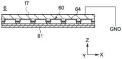
图30到图42是根据本公开第五实施方式的输入装置5的配置的图。在该实施方式中,将根据需要省略与上面提到的第一实施方式中类似的部分的描述。30 to 42 are diagrams of the configuration of the
总的来说,根据本实施方式的输入装置5的示意性配置类似于上面提到的应用于个人计算机的根据第一实施方式的输入装置1的配置。以类似于用于通用个人计算机(见图13)键盘的按键布置在输入装置5的上表面上画出字符或图案。例如,输入装置5可被用作用于个人计算机的输入装置或被配置为能够与平板终端通信的输入装置。In general, the schematic configuration of the
输入装置5不同于根据第一实施方式的输入装置1的方面在于关于操作元件(手指)的接近的电容元件的检测灵敏度对于各个按键或按键中包括的各个电容元件是可调整的。具体地,在按压操作中按键的“权重”对于每个按键或按键中包括的电容元件的每个区域是可调整的。应注意在本实施方式中,“关于手指的接近的电容元件的检测灵敏度”被认为是表示当手指在预定的距离接近各个传感器50的电容元件51的第一表面51a时从电容元件51的初始电容的电容变化量。The
图30是示出根据本实施方式的输入装置5的配置的框图。输入装置5包括多个传感器50、控制器c5、存储器55以及通信单元56。如随后所述,多个传感器50通过接收按压操作而被以与个人电脑的按键相同的方式使用,并通过接收触摸操作而被以与用于选择GUI(图像用户接口)的触控板等相同的方式使用。FIG. 30 is a block diagram showing the configuration of the
传感器50对应于用于通用个人计算机的键盘的各个按键,传感器50以与通用个人计算机(见图13)的键盘相似的按键布置被布置在X-Y平面上。传感器50中的每一个基于其布置或对其所分配的功能具有预定的尺寸和形状。The
传感器50的每一个均包括电容元件51和输入操作单元54,并在互电容系统中组成电容性传感器装置。电容元件51对应于根据第一实施方式的电容元件11,其电容通过与手指在输入操作单元54上所进行的触摸操作和按压操作相关的手指的接近被改变。输入操作单元54对应于根据第一实施方式的输入操作单元14。Each of the
控制器c5对应于根据第一实施方式的控制器c并包括判定单元c51和信号生成单元c52。判定单元c51基于电容元件51从参考电容的电容变化量判定手指与输入操作单元54的第二表面54a接触的触摸状态以及到手指按压对于传感器50中的每一个传感器的第二表面54a的按压状态的改变。信号生成单元c52基于判定单元c51的判定在触摸状态和按压状态之间生成不同操作信号。The controller c5 corresponds to the controller c according to the first embodiment and includes a determination unit c51 and a signal generation unit c52. The determination unit c51 determines the touch state of the finger in contact with the
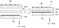
图31是输入装置5的局部截面图。传感器50中的每一个传感器包括电容元件51和输入操作单元54。电容元件51具有其上布置输入操作单元54的第一表面51a、第三表面51c、X电极52(第一电极)以及Y电极(第二电极)53。第三表面51c在z轴方向与第一表面51a相对。X电极52被布置为靠近第一表面51a(Z轴方向的上侧),Y电极53被布置为靠近在Z轴方向与X电极52相对的第三表面51c(Z轴方向的下侧)。FIG. 31 is a partial cross-sectional view of the
如在第一实施方式中那样,电容元件51一般具有包括其上形成X电极52的基板和其上形成Y电极53的基板的多个基材的层叠结构。基材的例子包括在第一实施方式中描述的PET、PC、PMMA(聚甲基丙烯酸甲酯)以及PI制成的塑料材料。也可使用玻璃环氧基板等。此外,可按需采用用于电子电路的通用生成方法作为形成X电极52和Y电极53的方法。例如,可采用:通过丝网印刷、凹版偏置印刷等在基板上印刷诸如银膏的导电墨水的方法;通过蚀刻铜箔形成图案的方法;通过蚀刻由溅射或汽相沉积形成的金属膜来形成图案的方法等。As in the first embodiment, the
图32和图33是示出电容元件51的制造示例的示意截面图。如图32所示地,电容元件51可通过经由粘合层B1接合具有形成其上的X电极52的第一基板51e和具有形成其上的Y电极53的第二基板51f来获得。例如,可使用压敏胶带、粘合剂等作为粘合层。此外,如图33所示,X电极52和Y电极53可被形成在基材51g的两面上。32 and 33 are schematic cross-sectional views showing a manufacturing example of the
参照图31,输入操作单元54被布置在第一表面51a上并具有受到手指f的操作的第二表面54a。第二表面54a包括一个凸部54c和凹部54b。对于每一个输入操作单元54形成凸部54c。凹部54b形成在与其他相邻输入操作单元54的边界部分,并围绕在凸部54c的周围。具体地,与第一实施方式不同,根据本实施方式的凹部54b被配置为根据每个按键的形状分割凸部54c。凸部54被配置为具有与通用键盘的每一个按键相同的尺寸和形状,诸如矩形柱状或截顶的四角锥状。31, the
应注意在凸部54c的顶部表面可进一步形成细微的凹部作为形成在Z轴方向上朝向电容元件51的高度差(见图2A到图2C)。在这种情况中,每一个凹部可被配置为具有对应于如图5H所示的各个按键的浮雕文字。It should be noted that a fine concave portion may be further formed on the top surface of the
图34是示出输入操作单元54的制造示例的示意截面图。如图34所示,输入操作单元54包括具有凹凸结构并经由粘合层B2被层叠在电容元件51上的膜F。作为这样的膜F,可采用诸如PET膜、硅树脂、橡胶材料这样的通用树脂材料制成的弹性绝缘材料。利用这种配置,接收手指f的按压操作的第二表面54a自身在Z轴方向被按压以使手指接近电容元件51,电容元件51判定按压状态。此外,例如,可使用粘合剂作为粘合层B2。FIG. 34 is a schematic cross-sectional view showing a manufacturing example of the
此外,只要当进行作为按压的按压操作时手指f可以接近电容元件51,输入操作单元54的配置和材料不限于上述这些。例如,在其中凸部54c还在其顶部表面包括凹部的情况中,输入操作单元54可由诸如聚对苯二甲酸乙二醇酯、聚乙烯和聚丙烯这样不易于被手指f按变形的树脂材料形成。因此,手指f变形进入凸部54c的凹部以判定按压状态。Further, the configuration and material of the
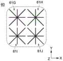
在本实施方式中,多个传感器50包括其中每个传感器均包括不同数目的电容元件51的多个传感器50。具体地,传感器50中的每个传感器均包括预定数目的电容元件51。因此,对各个传感器50调整初始电容,以便调整检测灵敏度。In the present embodiment, the plurality of
图35是从Z轴方向看的输入装置5的平面图,具体示出了电容元件51的X电极52和Y电极53的布线图案。X电极52和Y电极53在Z轴方向上彼此相对并形成如第一实施方式中那样的所谓交叉矩阵。X电极52包括在Y轴方向的整个范围上延伸的n列X电极52。Y电极53包括在X轴方向的整个范围上延伸m行Y电极53。此外,电容元件51被形成在X电极52和Y电极53彼此交叉的位置上。如图35所示,根据传感器50的布置以及传感器50中所包括的电容元件51的数量以不规则间距放置X电极52和Y电极53。35 is a plan view of the
这里,将描述各个传感器50中的电容元件51的布置的具体的示例。例如,传感器50A对应所谓“空格键”,八个电容元件51与其对应。同时,比传感器50A小的传感器50B对应所谓字符“S”,两个电容元件51与其对应。以这种方式,在这种实施方式中,各个传感器50并不具有相同数量的传感器元件51,但具有与传感器50的大小相符合的数量的电容元件51。因此,确保了用于判定触摸操作和按压操作的电容元件51的密度,例如,即使在传感50A周围部分的触摸操作也可以被检测到。Here, a specific example of the arrangement of the
同时,传感器50C对应于所谓字符“A”,尽管具有与传感器50B大体相同的尺寸,但四个电容元件51与其对应。因为与传感器50B相比,传感器50C位于输入装置5的周边部分,故用户用小拇指在传感器50C上进行输入操作。由于小拇指具有比其他手指小的面接触面积并比其他手指施加更小的力,因此如果传感器50具有与传感器50B相似级别的检测灵敏度,难以判定按压操作。因此,在传感器50c中的电容元件51的密度被增加得比传感器50B中的密度大,以便提高其中按压操作难以被检测的传感器50C的检测灵敏度。因此,即使当传感器50C被比按压传感器50B更小的按压力按压时,传感器50C的评价值也达到了第二阈值。以这种方式,分配至每个传感器50的电容元件51的数量和尺寸的调整导致了所谓“按键权重”的调整。Meanwhile, the
图36是示出在Z轴方向看的X电极52配置的平面图。图37是示出在Z轴方向上看的Y电极53的配置的平面图。在本实施方式中,X电极52包括线状电极的集合体(aggregate),Y电极53包括平面电极。具体地,X电极52包括从各个电容元件51的中央放射状延伸的线状电极的集合体。Y电极53包括由在X轴方向彼此相邻的多个传感器50共享的平面电极。FIG. 36 is a plan view showing the arrangement of the
图38A到图39B是用于描述如上所述的X电极52和Y电极53的作用的图。图38A和图38B示出了根据本实施方式的包括线状X电极52D和平面Y电极53D的电容元件51D的配置。图39A和图39B示出了根据现有技术的包括平面X电极52E和平面Y电极53E的电容元件51E的配置。图38A和图39A是分别示出包括X电极和Y电极的电容元件51平面图。图38B和39B分别是对应于图39A和39B的Y轴方向所示的截面图。出于示例的目的,作为操作元件的接近电容元件51D和51E的导体f51、f52和f53被示出。此外,附图中的箭头示意性地示出了电极之间和电极与导体f51、f52和f53之间的电容耦合状态。38A to 39B are diagrams for describing the roles of the
原则上,在电容系统的电容元件中,由于电极和操作元件(导体)之间的电容性耦合导致的电容变化量被检测到,因此,具有更大电极面积的电容元件的检测灵敏度可被提高。在互电容系统的电容元件中,在操作元件、X电极和Y电极之间发生互电容性耦合,并且基于互电容性耦合检测出X电极和Y电极之间的电容变化。In principle, in the capacitive element of the capacitive system, the amount of capacitance change due to the capacitive coupling between the electrode and the operating element (conductor) is detected, so the detection sensitivity of the capacitive element with a larger electrode area can be improved . In the capacitance element of the mutual capacitance system, mutual capacitive coupling occurs between the operating element, the X electrode, and the Y electrode, and a capacitance change between the X electrode and the Y electrode is detected based on the mutual capacitive coupling.
因此,如图39A和39B所示,在其中操作侧上的X电极52E被配置为平面的情况中,接近X电极52E和Y电极53E彼此相对的区域的导体f52由于X电极52E的存在而不与Y电极53E进行电容耦合,因此X电极52E和Y电极53E之间的电容并不改变。因此,在电容元件51E上形成了即使操作元件接近、X电极52E和Y电极53E之间的电容也难以改变的区域(下文中,被称为灵敏度低下区域)。具体地,为了增加在互电容系统中电容元件的灵敏度,需要增加电容面积并减少灵敏度低下区域的形成。Therefore, as shown in FIGS. 39A and 39B , in the case where the
同时,如图38A和38B所示,在其中操作侧上的X电极52D被配置为线状的情况中,X电极52D和Y电极53D彼此相对的区域具有更小的面积,这允许在Y电极53D与所有导体f51到f53之间发生的电容性耦合。因此,线状配置的X电极52D可消除在电容元件51D中的灵敏度低下区域的生成。此外,线状电极的密度的增加实现了电极面积的增加,这导致了关于操作元件的接近的检测灵敏度的进一步增加。Meanwhile, as shown in FIGS. 38A and 38B , in the case where the
图40A到图40P是分别示出电容元件51中的X电极52的变形例的图。图40A示出了多个线状电极从电容元件51的中央放射状形成的示例。在本示例中,在电容元件51的中央和其周边部分的电极密度不同,在中央的由于手指的接近产生的电容变化量比在周边部分大。图40B示出了在图40A的示例中放射状形成的多个线状电极中的一个电极比其他线状电极粗的示例。因此,粗线状电极的电容变化量比其他线状电极增加的多。进一步地,图40C和图40D分别示出了其中环形线状电极被布置在电容元件51的大体中央处并从中央放射状地形成的示例。因此,线状电极在中央处的集中度降低,防止了灵敏度低下区域的生成。40A to 40P are diagrams each showing a modification of the
图40E到图40H分别示出了形成为环状或矩形环状的多个线状电极被组合形成集合体的示例,通过这种配置,电极密度是可调整的,可消除灵敏度低下区域的生成。此外,图40I到40L分别示出其中在Y轴方向布置的多个线状电极被组合形成集合体。线状电极的形状、长度、间距等的调整提供了所期望的电极密度的示例。FIGS. 40E to 40H show an example in which a plurality of linear electrodes formed in a ring shape or a rectangular ring shape are combined to form an aggregate, respectively. With this configuration, the electrode density is adjustable and the generation of low-sensitivity regions can be eliminated. . In addition, FIGS. 40I to 40L respectively show where a plurality of linear electrodes arranged in the Y-axis direction are combined to form an aggregate. Adjustment of the shape, length, spacing, etc. of the wire electrodes provides examples of desired electrode densities.
此外,图40M到图40P分别示出了线状电极不对称地布置在X轴方向或Y轴方向的示例。X电极52形成为使电极密度是不均匀的,从而对于每个区域均调整电容元件51的检测灵敏度。因此,传感器50中的检测敏感度被细微地调整。例如,诸如图42所示的传感器50D这样的布置在输入装置5周边的传感器50在其中央侧具有比在其周边侧更易于进行手指操作的区域。因此,当布置在输入装置5中央侧的X电极52的密度比在周边侧增加得更多,可选择性增加传感器50在输入装置5中央侧的灵敏度。In addition, FIGS. 40M to 40P show examples in which the linear electrodes are asymmetrically arranged in the X-axis direction or the Y-axis direction, respectively. The
以这种方式,X电极52形成为线状电极的集合体可改变在电容元件51中X电极52的密度,这使得可以调整在第一表面51a中的电容元件51的灵敏度。In this way, forming the
同时,在Y电极53中,对在X轴方向彼此相邻的多个传感器50公共地布置的多个平面电极经由短的线状电极沿X轴方向连续布置。这样的配置增加了Y电极53的电极面积从而增加了检测灵敏度。此外,这样的配置赋予了抑制来自与输入装置5的第二表面54a的相反表面的电噪声的所谓屏蔽效应。Meanwhile, in the
图30所示的控制器c5的判定单元c51基于如第一实施方式的情况中那样从每个X电极52和每个Y电极53获得的电容变化量(见图11)计算手指f在输入操作单元54上的操作位置。应注意根据本实施方式的X电极52和Y电极53如图35所示地作为一个整体以不规则间距布置。因此,例如,通过将操作位置校正为使检测到的位置对应X电极52和Y电极53的相交位置,可计算从根据本实施方式的X电极52和Y电极53检测出的操作位置。可选地,可以预先建立表征按键布置和X电极52和Y电极53的相交位置之间的关系的表,对于控制器c5可以参照该表来识别被操作的按键来计算操作位置。The determination unit c51 of the controller c5 shown in FIG. 30 calculates the input operation of the finger f based on the capacitance change amount obtained from each
判定单元c51通过基于如第一实施方式中那样由X电极52或Y电极53组成的电容元件51中的电容变化量使用评价值来判定触摸状态或按压状态。对于各个电容元件51,设定预定的第一阈值和预定的第二阈值,并将阈值数据存储在存储器55中。The determination unit c51 determines the touch state or the pressed state by using the evaluation value based on the capacitance change amount in the
存储器55由RAM(随机访问存储器)、ROM(只读存储器)、其他半导体存储器等组成,并存储所计算的用户手指等操作位置的坐标、用于判定单元c51的各种计算的程序等。例如,ROM由非易失性存储器组成并存储与第一阈值和第二阈值相关的阈值数据、使判定单元c51执行诸如操作位置的计算的计算处理的程序。The
通信单元56被配置为能够将由信号生成单元c52生成的各种操作信号传输至显示装置(未示出)等。通信单元56的通信可由经由USB(通用串行总线)等的电缆或经由“Wi-Fi”(注册商标)、“蓝牙”(注册商标)等的无线电波进行。The
信号生成单元c52根据来自判定单元c51的输出信号生成操作信号。具体地,信号生成单元c52在触摸状态和按压状态之间生成不同的操作信号,并在检测按压状态的情况中,生成用于对应于键盘的各个按键的每个传感器50的唯一的操作信号。The signal generation unit c52 generates an operation signal based on the output signal from the determination unit c51. Specifically, the signal generating unit c52 generates different operation signals between the touch state and the pressing state, and in the case of detecting the pressing state, generates a unique operation signal for each
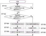
图41是输入装置5(控制器c5)的操作示例的流程图。此外,图42是包括两个电容元件51Da和51Db的传感器50D的示意性俯视图。这里,将描述在多个传感器50中的某个传感器50D包括两个电容元件51Da和51Db的情况中判定触摸状态或按压状态的方法。应注意判定单元c51根据以上的判定和从X电极52和Y电极53获得的电容变化量计算手指的操作位置,这是与第一实施方式相同的操作,其描述将被略去。Fig. 41 is a flowchart of an operation example of the input device 5 (controller c5). Furthermore, FIG. 42 is a schematic plan view of a
首先,判定单元c51将各个传感器50的电容改变的值转换为预定的评价值,并通过控制器c5的输出判定电路在预定的时间段内重复地输出评价值。电容元件51中的电容变化量的最大值、X组合值、以及Y组合值可用于作为第一实施方式中的评价值。之后,判定单元c51判定传感器50的各个电容元件51的评价值是否等于或大于第一阈值(步骤ST101)。First, the determination unit c51 converts the value of the capacitance change of each
在传感器50D的电容元件51Da和电容元件51Db中的至少一个元件的评价值等于或大于第一阈值的情况中(在步骤ST101中的是),判定单元c51判定评价值是否等于或大于第二阈值(步骤ST102)。在两个电容元件51Da和51Db的评价值均小于第二阈值的情况下(在步骤102中的否),判定单元c51判定传感器50D处于触摸状态(步骤ST103)。In the case where the evaluation value of at least one of the capacitive element 51Da and the capacitive element 51Db of the
此外,判定单元c51向信号生成单元c52输出由此得到的结果。被输入结果的信号生成单元c52生成用于移动指针等的操作信号(步骤ST104)(见图16)。进一步地,信号生成单元c52向通信单元56输出操作信号(步骤ST105)。Further, the determination unit c51 outputs the result thus obtained to the signal generation unit c52. The signal generation unit c52 to which the result is input generates an operation signal for moving the pointer or the like (step ST104 ) (see FIG. 16 ). Further, the signal generating unit c52 outputs an operation signal to the communication unit 56 (step ST105).
另一方面,在电容元件51Da和电容元件51Db中的至少一个元件的评价值等于或大于第二阈值的情况中(在步骤ST102中的是),判定单元c51判定所检测的传感器50D处于按压状态(步骤ST106)。此外,判定单元c51向信号生成单元c52输出由此得到的结果。被输入结果的信号生成单元c52生成对传感器50D唯一的操作信号(步骤ST107)(见图15)。进一步地,信号生成单元c52向通信单元56输出操作信号(步骤ST108)。On the other hand, in the case where the evaluation value of at least one of the capacitive element 51Da and the capacitive element 51Db is equal to or greater than the second threshold value (YES in step ST102 ), the determination unit c51 determines that the detected
判定单元c51继续基于电容改变的输出值重复判定评价值是否等于或大于第一阈值(步骤ST101)。The determination unit c51 continues to repeatedly determine whether the evaluation value is equal to or greater than the first threshold value based on the output value of the capacitance change (step ST101 ).
如上所述,即使传感器50包括多个电容元件51,根据本实施方式的输入装置5也可以判定传感器50中的触摸状态或按压状态。因此,输入装置5可被用作具有键盘和指针装置功能的输入装置。As described above, even if the
此外,根据上述的实施方式,调整分配至每个传感器50的电容元件51的数量或尺寸以使输入装置5中的传感器50的初始电容可被调整。因此,可基于输入装置5中的传感器50的布置、传感器50所占用的面积尺寸、每个传感器50的布置或使用频率等调整传感器50的检测灵敏度。Furthermore, according to the above-described embodiment, the number or size of the
此外,电容元件51的X电极52形成为线状电极的集合体使得很容易改变在每个电容元件51中的X电极52的的形状,这使得可以调整初始电容。因此,按压操作的按键的“权重”对于每个按键或其中放置电容元件的按键的每个区域是可调整的。此外,可以抑制妨碍Y电极53和手指之间的电容性耦合的所谓灵敏度低下区域的生成。In addition, the formation of the
此外,Y电极53包括平面电极,这可以提供产生遮蔽效果的配置。Furthermore, the
(第六实施方式)(Sixth Embodiment)
图43到图50B是用于描述根据本公开的第六实施方式的输入装置6的图。在本实施方式中,将根据需要省略类似于上面提到的第一和第五实施方式中的那些的部分。43 to 50B are diagrams for describing the
图43是示出根据本实施方式的输入装置6的配置的框图。输入装置6包括分别对应根据第五实施方式的输入装置5中的多个传感器50、控制器c5、存储器55以及通信单元56的多个传感器60、控制器c6、存储器65以及通信单元66,将根据需要省略其描述。FIG. 43 is a block diagram showing the configuration of the
输入装置6的控制器c6包括判定单元c61和信号生成单元c62。判定单元c61通过使用基于由X电极62或Y电极63形成的电容元件61的电容变化量的评价值判定触摸状态或按压状态。判定中所用的第一和第二阈值被存储在存储器65的ROM中作为阈值数据,并在根据需要载入RAM后用于第一和第二阈值的判定。The controller c6 of the
根据本实施方式的控制器c6还包括计算单元c63。计算单元c63。如上所述,计算单元c63基于电容元件61的检测灵敏度等改变第二阈值。The controller c6 according to the present embodiment further includes a calculation unit c63. Computing unit c63. As described above, the calculation unit c63 changes the second threshold value based on the detection sensitivity of the
图44是示出传感器60的配置的示意性截面图。传感器60如第五实施方式中那样包括电容元件61和输入操作单元64。电容元件61具有包括其上形成了X电极62的基板和其上形成Y电极63的基板的多个基材的层叠结构。FIG. 44 is a schematic cross-sectional view showing the configuration of the
根据本实施方式的多个传感器60包括其中每个均包括不同数量的电容元件61的多个传感器60。在本实施方式中,每个传感器60包括一个或多个电容元件61、即,对应每个传感器60的尺寸(占用面积)的预定数量的电容元件61。The plurality of
这里,取决于电极宽度、形成电容元件61的基材的厚度、电介质常数等,传感器60在关于手指的电容元件61的电容改变的灵敏度上可彼此不同。这样,基于传感器60的电容改变的灵敏度设定第二阈值以实现对每个传感器60的触摸或按压状态的判定的一致性。Here, the
下文中,将描述用于设定用于根据本实施方式的输入装置6中的按压状态的判定的第二阈值的操作示例。这里,例如,将描述在运送作为产品的输入装置6之前设定第二阈值初始值的情况中的操作示例。Hereinafter, an operation example for setting the second threshold value for determination of the pressing state in the
首先,判定单元c61基于输出自诸如手指这样的操作元件未接近的每个电容元件61的电信号预先计算此时获得的电容(初始电容)。该初始电容值可被输出至存储器65并存储。First, the determination unit c61 calculates in advance the capacitance (initial capacitance) obtained at this time based on the electric signal output from each
图45是传感器60的示意性截面,示出了其中基本平整的金属板f6被放置在输入操作单元64的第二表面64a上的状态。金属板f6被形成为覆盖所有传感器60的输入操作单元64的尺寸并被如图所示接地。这时,每个电容元件61的电容被从当诸如金属板f6和手指的导体并不对其靠近时的初始电容改变预定的量。变化量被视为当诸如手指的操作元件接近每个电容元件61固定距离时获得的电容变化量,并被认为是每个电容元件61关于手指接近的检测灵敏度。45 is a schematic cross section of the
判定单元c61由初始电容和当金属板f6被放置时所获得的电容之间的差异计算关于电容元件61的电容变化量。这些值被输出至存储器65并与初始电容值等一起被存储为电容元件61的电容变化量的数据。此外,这些值可被输出至通信单元66并被显示在显示装置的监视器(未示出)等。The determination unit c61 calculates the capacitance change amount with respect to the
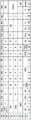
图46是示出输入装置6中包括的两个电容元件61E和61F的电容变化量的表的示例。图46中所示的表的数字值以pF为单位表示。用于电容的单位仅仅是示例,并取决于所用IC(集成电路)的电容检测的范围可以是例如“fF”、“nF”或“μF”。在图46中,电容元件61E的初始电容是3.1pF,电容元件61F的初始电容是3.2F。当金属板f6被放置在对应电容元件61E和61F的输入操作单元64的第二表面64a上时,电容元件61E的电容和电容元件61F的电容分别被改变至2.8pF和2.78pF。在初始电容和当金属板f6被放置时的电容之间的差别在电容元件61E中是0.3pF,在电容元件61F中是0.42pF。这些值对应关于手指接近的检测灵敏度。FIG. 46 is an example of a table showing the capacitance change amounts of the two capacitive elements 61E and 61F included in the
此外,计算单元c63还可对这些电容变化量数据进行预定的计算处理以设定由此计算的结果值为用于检测灵敏度的评价值(下文中,被称为灵敏度评价值)。例如,在将电容变化量乘以100的计算处理中,电容元件61E的灵敏度评价值是30,电容元件61F的灵敏度评价值是42。因此,灵敏度评价值可被设定为整数,这便于检测灵敏度的评价。In addition, the calculation unit c63 may also perform predetermined calculation processing on these capacitance change amount data to set the resultant value thus calculated as an evaluation value for detection sensitivity (hereinafter, referred to as a sensitivity evaluation value). For example, in the calculation process of multiplying the capacitance change amount by 100, the sensitivity evaluation value of the capacitive element 61E is 30, and the sensitivity evaluation value of the capacitive element 61F is 42. Therefore, the sensitivity evaluation value can be set to an integer, which facilitates the evaluation of detection sensitivity.
此外,计算单元c63比较电容元件61的灵敏度评价值的大小以使可评价各个电容元件61的检测灵敏度的大小。在上面的示例中,很容易评价出电容元件61F的灵敏度高于电容元件61E的灵敏度。Further, the calculation unit c63 compares the magnitudes of the sensitivity evaluation values of the
此外,计算单元c63对这些灵敏度的评价值进行预定的计算处理并计算每个电容元件61的第二阈值。作为这样的计算处理的示例,加或减恒值β。例如,现设β=5,从评价值的每一个中减去β,对于电容元件61E获得表达式30-5=25,对于电容元件61F获得42-5=37。以这种方式,进行计算,得出电容元件61E的第二阈值的结果是25和电容元件61F的第二阈值的结果是37。Further, the calculation unit c63 performs predetermined calculation processing on the evaluation values of these sensitivities and calculates the second threshold value of each
应注意第一阈值也以相同的方式设定。例如,计算单元c63基于由判定单元c61所计算的初始电容与当金属板被放置时的电容之间的差异进行预定的计算处理,该预定的计算处理不同于当设定第二阈值时所进行的计算处理。由此,可设定对应每个电容元件61的检测灵敏度的第一阈值。It should be noted that the first threshold is also set in the same way. For example, the calculation unit c63 performs predetermined calculation processing different from that when the second threshold value is set based on the difference between the initial capacitance calculated by the determination unit c61 and the capacitance when the metal plate is placed calculation processing. Thereby, the first threshold value corresponding to the detection sensitivity of each
计算单元c63将所计算的第一和第二阈值存储在存储器65中。因此,存储器65可以存储关于电容元件61的第一和第二阈值的数据作为“阈值数据”。The calculation unit c63 stores the calculated first and second threshold values in the
例如,对于每一个电容元件61,可以使上述的值β不同。由此,可以设定每个电容元件61的第二阈值,并且可以使得对于每个电容元件61的关于按压操作的检测灵敏度不同。For example, the above-mentioned value β may be made different for each
图47和图48是示出如上述一个传感器60包括四个电容元件61的操作示例那样地设定第二阈值的示例的图。图47是示出传感器60中电容元件61G、61H、61I和61J的布置的示意平面图。图48是示出关于电容元件61G到61J的阈值设定的数据示例的图。47 and 48 are diagrams showing an example of setting the second threshold value as in the above-described operation example in which one
电容元件61G到61J分别包括具有基本相同尺寸和形状的X电极,并且初始值、当金属板f6被放置时的电容、和这些电容的差异(即电容变化量)具有相同的值。这样,电容元件61G、61H和61J的值β被设为5,电容元件61I的值β被设为7以使电容元件61G、61H和61J的第二阈值不同于电容元件61I。The
由此,在电容元件61G到61J中,仅电容元件61I的第二阈值小于其他电容元件61G、61H和61J的的第二阈值。因此,在布置有电容元件61I的传感器60的区域中,可判定由具有比传感器60的其他区域更小的按压力或具有更少接触面积的手指引起的按压状态。Thus, among the
以这种方式,根据本实施方式的输入装置6可分别设定用于每个传感器60或电容元件61的第一和第二阈值。由此,可对于每个传感器60或传感器60内的电容元件61改变按压状态和触摸状态的检测灵敏度。因此,对于对应每个按键的每个传感器60或对于传感器60的每个区域可改变所谓“按键权重”。In this way, the
图49A到图50B是用于描述用于设定上述阈值数据的示例的图。图49A和图49B是输入装置6的示意性截面图。图50A和图50B是分别示出基于从包括电容元件61K、61L、61M和61N的传感器60的初始电容的电容变化量的灵敏度评价值的数据示例的图。应注意图50A和图50B中所示的表的P1到P4表示如下述地获得灵敏度评价值的实验。49A to 50B are diagrams for describing an example for setting the above-described threshold value data. 49A and 49B are schematic cross-sectional views of the
在本示例中,金属板被重复地多次放置在传感器60上(这里,四次),根据在各个情况中输出的灵敏度评价值的平均值计算得出第二阈值。例如,图49A示出了金属板f7不放置在传感器60上的形式。在这种情况中,参照图50A,各个电容元件61K到61N的灵敏度评价值是0。随后,例如,通过使用预定的夹具等,金属板f7被重复四次放置在传感器60上(图49B)。由此,判定单元c6计算出如图50B所示的各个电容元件61K到61N的灵敏度评价值。上述这些值的平均值数据被存储在存储器65的ROM等中,并且使用这些数据,计算第二阈值。因此,可基于更精确的检测灵敏度数据设定阈值。In this example, the metal plate is repeatedly placed on the sensor 60 a plurality of times (here, four times), and the second threshold value is calculated from the average value of the sensitivity evaluation values output in each case. For example, FIG. 49A shows a form in which the metal plate f7 is not placed on the
以这种方式,不同于现有技术中的具有机械配置的膜键盘等,根据本实施方式的输入装置6可通过仅仅改变用于控制器c6的参数设定来改变“按键权重”。因此,很容易设定按键权重而无需改变输入装置6的配置。In this way, the
通过这种配置,可轻易进行按压操作的输入装置6可被提供给手指力弱的孩子或老年人,并且可根据诸如习惯左手、习惯右手、和手或手指的尺寸这样的个体用户的特征来进行输入装置6的定制。以这种方式,根据本实施方式,可通过仅改变参数设定来获得满足用户特征等的所期望的操作体验。With this configuration, the
(第七实施方式)(Seventh Embodiment)
图51到图54是用于描述根据本公开的第七实施方式的输入装置7(电子设备z7)的图。在本实施方式中,类似于上面提到的第一和第六实施方式中的那些部分将根据需要略去。51 to 54 are diagrams for describing the input device 7 (electronic device z7 ) according to the seventh embodiment of the present disclosure. In the present embodiment, portions similar to those in the above-mentioned first and sixth embodiments will be omitted as necessary.
图51是示出根据本实施方式的输入装置7被应用于作为电子设备z7个人计算机的示例中的电子设备z7的框图。电子设备z7包括输入装置7、处理装置p7、以及输出装置(显示装置)o7。FIG. 51 is a block diagram showing an electronic device z7 in which the
输入装置7包括分别对应于根据第六实施方式的输入装置6中的多个传感器60、控制器c6、存储器65以及通信单元66的多个传感器70、控制器c7、存储器75以及通信单元76,其描述将根据需要略去。The
输入装置7的控制器c7包括判定单元c71和信号生成单元c72。判定单元c71通过使用基于由X电极或Y电极形成的电容元件71的电容变化量的评价值判定触摸状态或按压状态。判定中所用的第一和第二阈值被存储在存储器75的ROM中作为阈值数据,计算单元c73如下述地基于来自处理装置p7的命令等改变第二阈值。The controller c7 of the
处理装置p7包括控制器pc7、存储器p75和通信单元p76和p77。The processing device p7 includes a controller pc7, a memory p75 and communication units p76 and p77.
通信单元p76被配置为传输和接收由输入装置7的信号生成单元c72生成的各种操作信号。例如,在桌面型电子设备z7的情况中,通信一般使用经由USB的电缆等进行。应注意,在笔记本型中,电子设备z7可被配置为没有通信单元p76并被配置为处理装置p7的控制器pc7也作为输入装置7的控制器c7。The communication unit p76 is configured to transmit and receive various operation signals generated by the signal generation unit c72 of the
另一方面,通信单元p77连接至诸如互联网这样的通信网络。例如,通信单元p77被用于向处理装置p7下载诸如应用程序的预定程序。通信单元p77的信息的传输和接收可如在高速数据传输中那样通过诸如LAN电缆这样的电缆或通过无线电波进行。On the other hand, the communication unit p77 is connected to a communication network such as the Internet. For example, the communication unit p77 is used to download a predetermined program such as an application program to the processing device p7. Transmission and reception of information by the communication unit p77 can be performed through a cable such as a LAN cable or through radio waves as in high-speed data transmission.
控制器pc7一般由CPU构成。在这种实施方式中,控制器pc7根据存储器p75存储的程序基于接收自输入装置7的信息执行各种功能。例如,在对于对应于字符“A”的按键的输入装置7的传感器70被判定为按压状态的示例中,在信号生成单元c72中生成的操作信号被传输至通信单元p76。控制器pc7基于操作信号生成用于在显示装置o7上显示字符“A”的命令信号。The controller pc7 is generally constituted by a CPU. In this embodiment, the controller pc7 executes various functions based on the information received from the
此外,控制器pc7执行用于调整传感器灵敏度的实用软件,该软件被存储在存储器p75中(下文中,被称为灵敏度调整软件)并在显示装置o7的监视器M上显示软件的阈值输入图像。此外,控制器pc7根据用户向输入装置7的输入生成用于改变阈值数据中的第一和第二阈值的命令信号。Furthermore, the controller pc7 executes utility software for adjusting the sensor sensitivity, which is stored in the memory p75 (hereinafter, referred to as sensitivity adjustment software) and displays the threshold input image of the software on the monitor M of the display device o7 . Further, the controller pc7 generates a command signal for changing the first and second threshold values in the threshold value data according to the user's input to the
存储器p75如在存储器65中那样由RAM、ROM、其他半导体存储器等构成,并存储控制器pc7所用的用于多种计算的程序等。例如,ROM由非易失性存储器构成并存储设定值或用于指示控制器pc7改变阈值数据的灵敏度调整软件。此外,这些预先存储的程序可被临时加载到RAM并由控制器pc7执行。The memory p75 is constituted by RAM, ROM, other semiconductor memories, etc. as in the
显示装置o7包括监视器M并基于控制器pc7所生成的命令信号在监视器M上显示预定的图像。例如,接收用于显示字符“A”的命令信号的显示装置o7基于命令信号在监视器M上显示字符“A”(见图15)。可选地,还可以显示用于改变每个电容元件71的阈值数据的阈值设定图像等(见图52到54)。The display device o7 includes a monitor M and displays a predetermined image on the monitor M based on a command signal generated by the controller pc7. For example, the display device o7 that receives the command signal for displaying the character "A" displays the character "A" on the monitor M based on the command signal (see FIG. 15 ). Alternatively, a threshold value setting image or the like for changing the threshold value data of each
下文中,将描述根据本实施方式的电子设备z7的操作示例。这里,所描述的是通过用户的输入操作启动灵敏度调整软件,执行改变每个电容元件的第二阈值的输入操作的示例。Hereinafter, an operation example of the electronic device z7 according to the present embodiment will be described. Here, described is an example in which the sensitivity adjustment software is activated by the user's input operation, and the input operation of changing the second threshold value of each capacitive element is performed.
响应用户的输入操作等,处理装置p7(控制器pc7)首先访问存储器p75以启动灵敏度调整软件。这时用户的输入操作可以是例如选择显示在监视器M上的代表传感器灵敏度调整软件的图标的操作。因此,用户所用的用于改变阈值数据的阈值设定图像被显示在显示装置o7的监视器M上。具体地,基于用户的操作,电子设备z7从判定上述的触摸和按压状态的输入操作模式切换模式至改变第二阈值的改变模式。In response to a user's input operation or the like, the processing device p7 (controller pc7 ) first accesses the memory p75 to start the sensitivity adjustment software. The user's input operation at this time may be, for example, an operation of selecting an icon representing the sensor sensitivity adjustment software displayed on the monitor M. Therefore, the threshold value setting image used by the user for changing the threshold value data is displayed on the monitor M of the display device o7. Specifically, based on the user's operation, the electronic device z7 switches the mode from the input operation mode in which the above-described touch and press state is determined to the change mode in which the second threshold value is changed.
接着,电子设备z7接收关于多个传感器70中的一部分的第二阈值的输入,并基于由此输入的指令值生成改变命令信号。本文所用的“指令值”可以是关于已改变的第二阈值的值或关于改变之前或之后的第二阈值的增量和减量的值。此外,“指令值”可以是第二阈值本身、对应于第二阈值的灵敏度评价值等。Next, the electronic device z7 receives an input of a second threshold value for a portion of the plurality of
例如,用户选择阈值设定图像中对应于需要改变的电容元件71的某些单元格,并在之后输入指令值至这些单元格。由此,电子装置z7的控制器pc7生成用于基于指令值改变阈值数据的改变命令信号。改变命令信号被经由通信单元p76输出至输入装置7的控制器c7。For example, the user selects certain cells in the threshold value setting image corresponding to the
基于改变命令信号,输入装置7的控制器c7控制存储器75以改变存储器75中存储的阈值数据。因此,多个传感器70中的一部分的第二阈值被改变为不同于其他传感器70的第二阈值的值,阈值数据通过用户输入被改变为具有预定的值。Based on the change command signal, the controller c7 of the
此外,处理装置p7的控制器pc7基于由指令值的输入操作所生成的操作信号生成用于输出至显示装置o7的命令信号。显示装置o7基于命令信号在监视器M上显示改变后的阈值设定图像。Further, the controller pc7 of the processing device p7 generates a command signal for output to the display device o7 based on the operation signal generated by the input operation of the command value. The display device o7 displays the changed threshold value setting image on the monitor M based on the command signal.
在阈值数据改变之后,通过用户预定的输入操作,监视器M上的阈值设定图像的显示结束。After the threshold value data is changed, by a predetermined input operation by the user, the display of the threshold value setting image on the monitor M ends.
图52到图54是示出显示在显示装置o7的监视器M上的阈值设定图像的示例的图。例如,在阈值设定图像中,其上显示预定的文字或数字的单元格被如在电子表格软件中所见那样布置。传感器70被分配至如图52所示的各个单元格。应注意图52所示图像可被显示在监视器M上作为灵敏度调整软件等的初始图像,或可不显示在其上。52 to 54 are diagrams showing examples of threshold value setting images displayed on the monitor M of the display device o7. For example, in the threshold setting image, cells on which predetermined characters or numbers are displayed are arranged as seen in spreadsheet software.
图53示出了阈值设定图像的示例,其中传感器70所包括的电容元件71的尚未改变的第二阈值被显示在预定的单元格处。这些值可以在运送时就被设定的初始值(见图45和49B)。可选地,这些值可以是对应于第二阈值的灵敏度评价值。FIG. 53 shows an example of a threshold value setting image in which the second threshold value of the
图54示出了阈值设定图像的示例,其中传感器70所包括的电容元件71的已被改变的第二阈值被显示在预定的单元格处。在图54所示的阈值设定图像中,各个单元格中所示的数字值被改变为总体上比图53中所示的阈值设定图像的单元格中所显示的数字值更小的值。这样,传感器70的第二阈值向更小值的改变使得控制器c7可以判定更小电容变化量的按压状态,这可以增加传感器70的检测灵敏度。FIG. 54 shows an example of a threshold value setting image in which the changed second threshold value of the
此外,例如,作为改变第二阈值的具体操作,可使用直接将指令值输入对应于希望改变的传感器70的单元格的方法。可选地,可使用在阈值设定图像上单独设置不同于对应于传感器70的单元格的输入单元格,并将诸如第二阈值的增量或减量值这样的指令值输入输入单元格的方法。被输入输入单元格的信息反映多个传感器70的第二阈值的增量和减量,这使得传感器70的第二阈值可被集体增加或减少。例如,独立地对于布置在输入装置7周边区域的传感器70和对于布置在输入装置中央的传感器70输入第二阈值的增量或减量,这实现了对于这些区域中的每一个区域的第二阈值的增量或减量。Further, for example, as a specific operation of changing the second threshold value, a method of directly inputting an instruction value into a cell corresponding to the
如上所述,根据本实施方式的电子设备z7可基于用户的输入操作改变阈值数据。因此,例如,当使用电子设备z7的用户需要更轻的操作触感时,整个第二阈值可通过上述的软件被改变为更小的值来实现期望的操作触感。此外,例如,在期望用于游戏操作等的特定按键的操作触感更轻的情况中,对应于特定按键的传感器70的电容元件71的第二阈值可通过上述软件被改变。As described above, the electronic device z7 according to the present embodiment can change the threshold value data based on the user's input operation. Therefore, for example, when a user using the electronic device z7 needs a lighter operation tactile sensation, the entire second threshold value can be changed to a smaller value by the above-mentioned software to achieve the desired operation tactile sensation. Further, for example, in the case where a lighter operation touch feeling of a specific key for game operation or the like is desired, the second threshold value of the
此外,上述的软件可以从例如互联网下载,以实现其升级。因此,可提供用户友好的软件。此外,使用互联网上的服务器等,多个用户可共享使用多种调试过的信息。In addition, the above-mentioned software can be downloaded from, for example, the Internet to enable its upgrade. Therefore, user-friendly software can be provided. In addition, using a server on the Internet, etc., a plurality of users can share and use various kinds of debugged information.
尽管在上面的描述中仅描述了阈值数据中的第二阈值的改变,但第一阈值数据也可以相同的方式被改变。由此,例如,即使当用户希望以用小拇指的指甲尖的轻触进行触摸操作时,也可以通过将整个第一阈值改变为更小的值来实现触摸操作。Although only the change of the second threshold value in the threshold value data is described in the above description, the first threshold value data can also be changed in the same manner. Thus, for example, even when the user wishes to perform a touch operation with a light touch with the tip of the nail of the little finger, the touch operation can be achieved by changing the entire first threshold value to a smaller value.
在上面的描述中,描述了将第一和第二阈值改变为更小的值。相反地,第一和第二阈值可被改变为更大的值。因此,可以将触摸状态或按压状态设定为更加难以检测,这可以防止例如误操作的发生。In the above description, it was described that the first and second threshold values were changed to smaller values. Conversely, the first and second thresholds may be changed to larger values. Therefore, the touch state or the pressing state can be set to be more difficult to detect, which can prevent, for example, the occurrence of erroneous operations.
如上所述,根据本实施方式,检测灵敏度可根据用户的操作方法或诸如按压力这样的用户的特点进行调整。因此,可定制针对每个用户的输入操作性,从而可提供具有对于每个用户的更高的操作性的输入装置。As described above, according to the present embodiment, the detection sensitivity can be adjusted according to the user's operation method or the user's characteristics such as pressing force. Therefore, the input operability for each user can be customized, so that an input device having higher operability for each user can be provided.
此外,在上面的描述中,将个人计算机作为电子设备z7的示例进行了描述,但也可采用如下的变形例。In addition, in the above description, the personal computer has been described as an example of the electronic device z7, but the following modified examples may also be employed.
(包括平板终端的信息处理设备)(Including tablet terminal information processing equipment)
将描述包括例如平板终端z70的信息处理设备z71被应用于根据本实施方式的电子设备z7的示例。An example in which the information processing apparatus z71 including, for example, the tablet terminal z70 is applied to the electronic apparatus z7 according to the present embodiment will be described.
图55到图57是分别示出输入装置7与平板终端z70的配置的示意图。信息处理设备z71包括输入装置7和平板终端z70。平板终端z70还包括作为处理装置p7的处理装置p71和作为显示装置o7的显示装置o71。显示装置o71包括触摸板监视器TM。触摸板监视器TM也作为平板终端z70的输入操作单元并被配置为接收用户的触摸操作。55 to 57 are schematic diagrams showing the configurations of the
这里,输入装置7和平板终端z70经由输入装置7的通信单元76和平板终端z70(处理装置p71)的通信单元p76彼此电连接。例如,图55示出了其中输入装置7和平板终端z70被配置为经由输入输出端彼此可拆卸的示例。在这种情况中,通信单元76和通信单元p76包括形成其中的输入输出端子。另一方面,图56示出了输入装置7和平板终端z70经由USB端子等通过电缆彼此连接的示例。此外,图57示出了输入装置7和平板终端z70通过使用诸如“Wi-Fi”(注册商标)、“ZigBee”(注册商标)和“蓝牙”(注册商标)的无线电波的装置间通信而彼此连接的示例。Here, the
在该变形例中,灵敏度调整软件被存储在平板终端z70的存储器p75中。例如,灵敏度调整软件被从互联网等经由例如通信单元p77下载至平板终端z70。可选地,可将软件从诸如CD-ROM(只读光盘存储器)的记录介质安装。因此,用户可操作平板终端z70改变存储在输入装置7的存储器75中的阈值数据。In this modification, the sensitivity adjustment software is stored in the memory p75 of the tablet terminal z70. For example, the sensitivity adjustment software is downloaded to the tablet terminal z70 from the Internet or the like via, for example, the communication unit p77. Alternatively, the software may be installed from a recording medium such as a CD-ROM (Compact Disc Read Only Memory). Therefore, the user can operate the tablet terminal z70 to change the threshold value data stored in the
例如,用户启动平板终端z70的灵敏度调整软件以在触摸板监视器TM上显示阈值设定图像。之后,在触摸板监视器TM上进行预定的输入操作以使显示在阈值设定图像中的灵敏度评价值改变。For example, the user activates the sensitivity adjustment software of the tablet terminal z70 to display the threshold setting image on the touch panel monitor TM. After that, a predetermined input operation is performed on the touch panel monitor TM to change the sensitivity evaluation value displayed in the threshold value setting image.
平板终端z70的控制器pc7基于在触摸板监视器TM上进行的输入操作生成用于改变阈值数据的改变命令信号。改变命令信号经由通信单元p76和通信单元76被输出至输入装置7的控制器c7。The controller pc7 of the tablet terminal z70 generates a change command signal for changing the threshold value data based on the input operation performed on the touch panel monitor TM. The change command signal is output to the controller c7 of the
输入装置7的控制器c7基于改变命令信号控制存储器75以改变存储在存储器75中的阈值数据,阈值数据通过用户的输入被改变为预定的值。The controller c7 of the
在该变形例中,对于每个用户的输入可操作性还可被定制。根据本实施方式的输入装置7可仅通过参数设定改变按键权重、即检测灵敏度。因此,将灵敏度调整软件下载至与输入装置7不同的平板终端z70也可使输入装置7的按键权重被改变。In this variant, the input operability for each user can also be customized. The
上文中,描述了本公开的实施方式,但本公开并不限于上述的实施方式,不用说,在不背离本公开本质的前提下可进行各种不同的变化。Hereinabove, the embodiments of the present disclosure have been described, but the present disclosure is not limited to the above-described embodiments, and it goes without saying that various changes can be made without departing from the essence of the present disclosure.
图58A和图58B是分别示出根据上述第五实施方式的输入装置5的变形例的图,示出了电容元件51的X电极52的配置示例。图58A示出了电容元件51Q中包括的X电极52Q。图58B示出了电容元件51R中所包括的电极52R。X电极52Q和52R分别具有不同的尺寸和形状,并具有基本相同的面积。因此,电容元件51Q和51R的初始电容可被设定为基本相同。58A and 58B are diagrams each showing a modification of the
例如,取决于控制器c5的特点,在每个电容元件51的初始电容彼此显著不同的情况中,难以调整增益,可能出现不正常工作的电容元件51。由于根据本公开的本实施方式的电容元件51包括由线状电极组成的X电极52,所以容易控制电极面积并易于调整初始电容。由此,即使在电容元件51Q和51R如图58A和图58B所示分别具有不同的尺寸等的情况中,其初始电容可被设定为大致相同,可抑制上述故障的发生。For example, depending on the characteristics of the controller c5, in the case where the initial capacitances of each
此外,图59A到图59C是分别示出根据上述的第五实施方式的输入装置5的变形例的图。图59A示出了Y电极53的一个平面电极的配置示例。另一方面,图59B和图59C分别示出了采用具有较密布置的线状电极的集合体,而不是平面电极的示例。在图59B所示的示例中,Y电极53包括线状电极的格子形集合体。在图59C所示的示例中,Y电极53包括线状电极的网状的集合体。以这样的方式,即使当Y电极53由线状电极相对密集地布置的集合体构成时,Y电极53也可发挥遮蔽效果。In addition, FIGS. 59A to 59C are diagrams each showing a modification of the
此外,由于根据上述的每个实施方式的输入装置采用电容系统,可检测到三维空间中的操作元件的输入操作。因此可检测到诸如在距离输入操作单元一定距离处的“划动(swipe)”操作等的所谓姿势操作。在上述的实施方式中,例如,当第一阈值减少至比通常触摸检测用值小的值时,还可以轻易地检测这样的姿势操作。Furthermore, since the input device according to each of the above-described embodiments adopts a capacitance system, an input operation of an operation element in a three-dimensional space can be detected. Therefore, a so-called gesture operation such as a "swipe" operation at a distance from the input operation unit can be detected. In the above-described embodiment, for example, when the first threshold value is reduced to a value smaller than the value for normal touch detection, such a gesture operation can also be easily detected.
例如,当输入装置被配置为在厚度方向上透明,作为输出装置的显示装置被放置在与输入操作单元相反的表面,可获得触摸板显示器。因此,在显示装置上可用手指进行操作,从而可进行更多的直接操作,显著地提高可操作性。For example, when the input device is configured to be transparent in the thickness direction, and the display device as the output device is placed on the surface opposite to the input operation unit, a touch panel display can be obtained. Therefore, the display device can be operated with a finger, so that more direct operations can be performed, and the operability can be improved remarkably.
此外,在上述的实施方式中,输入装置具有平整的板状,但其形状并不限于此。例如,输入装置可被配置为使得输入操作单元具有弯曲的表面或可被配置为输入装置本身在其厚度方向上变形。In addition, in the above-described embodiment, the input device has a flat plate shape, but its shape is not limited to this. For example, the input device may be configured such that the input operation unit has a curved surface or may be configured such that the input device itself deforms in its thickness direction.
应注意本公开可采用下面的配置。It should be noted that the present disclosure may take the following configurations.
(1)一种传感器装置,包括:(1) A sensor device comprising:
电容元件,具有第一表面并被配置为通过将操作元件接近所述第一表面来改变其电容;以及a capacitive element having a first surface and configured to change its capacitance by approaching an operating element to the first surface; and
输入操作单元,被布置在所述第一表面上,所述输入操作单元具有在其上接收所述操作元件的操作的第二表面,并被配置为允许与所述第二表面接触的操作元件向所述第一表面移动。an input operation unit disposed on the first surface, the input operation unit having a second surface on which the operation of the operation element is received, and configured as an operation element allowing contact with the second surface move toward the first surface.
(2)根据(1)的传感器装置,其中,(2) The sensor device according to (1), wherein,
所述第二表面包括多个凹部。The second surface includes a plurality of recesses.
(3)根据(2)的传感器装置,其中,(3) The sensor device according to (2), wherein,
所述第二表面以弹性材料形成。The second surface is formed of an elastic material.
(4)根据(1)或(2)的传感器装置,其中,(4) The sensor device according to (1) or (2), wherein,
所述输入操作单元包括形成所述第二表面的弹性体。The input operation unit includes an elastic body forming the second surface.
(5)根据(1)到(4)中的任意一项的传感器装置,其中,(5) The sensor device according to any one of (1) to (4), wherein,
所述输入操作单元被布置在所述第一表面和所述第二表面之间,并还包括被配置为以弹性可变形的方式支持所述弹性体的支持部。The input operation unit is disposed between the first surface and the second surface, and further includes a support portion configured to support the elastic body in an elastically deformable manner.
(6)一种输入装置,包括:(6) An input device, comprising:
至少一个传感器,包括:At least one sensor, including:
电容元件,具有第一表面并被配置为通过将操作元件接近第一表面来改变其电容,以及a capacitive element having a first surface and configured to change its capacitance by bringing the operating element close to the first surface, and
输入操作单元,被布置在所述第一表面上,所述输入操作单元具有在其上接收所述操作元件的操作的第二表面,并被配置为允许与所述第二表面接触的操作元件向所述第一表面移动;以及an input operation unit disposed on the first surface, the input operation unit having a second surface on which the operation of the operation element is received, and configured as an operation element allowing contact with the second surface moving toward the first surface; and
控制器,包括判定单元,被配置为基于所述电容元件的电容的变化,判定第一状态以及从所述第一状态向第二状态的改变,第一状态是其中所述操作元件与所述第二表面接触的状态,第二状态是其中所述操作元件按压所述第二表面的状态。a controller including a determination unit configured to determine a first state and a change from the first state to a second state based on a change in the capacitance of the capacitive element, the first state being where the operating element and the A state in which the second surface is in contact, and the second state is a state in which the operating element presses the second surface.
(7)根据(6)的输入装置,其中,(7) The input device according to (6), wherein,
所述判定单元被配置为当所述电容元件的电容变化量等于或大于第一阈值时判定为所述第一状态,而当所述电容变化量等于或大于第二阈值时判定为所述第二状态,所述第二阈值大于所述第一阈值。The determination unit is configured to determine the first state when the capacitance change amount of the capacitive element is equal to or greater than a first threshold value, and to determine the first state when the capacitance change amount is equal to or greater than a second threshold value. In two states, the second threshold is greater than the first threshold.
(8)根据(6)或(7)所述的输入装置,其中,(8) The input device according to (6) or (7), wherein,
所述控制器进一步包括:信号生成单元,被配置为生成在所述第一状态和所述第二状态之间不同的操作信号。The controller further includes a signal generating unit configured to generate an operation signal that is different between the first state and the second state.
(9)一种输入装置,包括:(9) An input device, comprising:
多个传感器,各个传感器包括:Multiple sensors, each sensor includes:
电容元件,具有第一表面并被配置为通过将操作元件接近所述第一表面来改变其电容;以及a capacitive element having a first surface and configured to change its capacitance by approaching an operating element to the first surface; and
输入操作单元,被布置在所述第一表面上,所述输入操作单元具有在其上接收所述操作元件的操作的第二表面,并被配置为允许与所述第二表面接触的操作元件向所述第一表面移动;以及an input operation unit disposed on the first surface, the input operation unit having a second surface on which the operation of the operation element is received, and configured as an operation element allowing contact with the second surface moving toward the first surface; and
控制器,被配置为对于多个传感器中的每一个,基于所述电容元件的电容的改变,判定第一状态以及从所述第一状态向第二状态的改变,第一状态是其中所述操作元件与所述第二表面接触的状态,第二状态是其中所述操作元件按压所述第二表面的状态。a controller configured to, for each of the plurality of sensors, determine a first state and a change from the first state to a second state based on a change in capacitance of the capacitive element, the first state being where the A state in which the operating element is in contact with the second surface, and the second state is a state in which the operating element presses the second surface.
(10)根据(9)的输入装置,其中,(10) The input device according to (9), wherein,
所述多个传感器包括对于操作元件的接近电容元件的检测灵敏度各自不同的的多个传感器。The plurality of sensors includes a plurality of sensors each having different detection sensitivities with respect to the proximity capacitive element of the operation element.
(11)根据(10)的输入装置,其中,(11) The input device according to (10), wherein,
所述多个传感器包括各自具有不同数量的电容元件的多个传感器。The plurality of sensors includes a plurality of sensors each having a different number of capacitive elements.
(12)根据(9)到(11)中的任意一项的输入装置,其中(12) The input device according to any one of (9) to (11), wherein
电容元件具有与第一表面相对的第三表面,the capacitive element has a third surface opposite the first surface,
所述电容元件包括:The capacitive element includes:
第一电极,布置为靠近第一表面,以及a first electrode disposed proximate the first surface, and
第二电极,布置为靠近与第一表面相对的第三表面,以及第一电极,包括线状电极的集合体。The second electrode is disposed close to the third surface opposite the first surface, and the first electrode includes an aggregate of wire electrodes.
(13)根据(12)的输入装置,其中,(13) The input device according to (12), wherein,
第二电极包括平面电极。The second electrode includes a planar electrode.
(14)根据(9)到(13)中的任意一项的输入装置,其中,(14) The input device according to any one of (9) to (13), wherein,
控制器被配置为在所述电容元件的单元中,当所述电容元件的电容变化量等于或大于所述第一阈值并小于所述第二阈值时,判定为所述第一状态;在所述电容元件所属的传感器的单元中,当所述电容变化量等于或大于所述第二阈值时,判定为所述第二状态。The controller is configured to, in the unit of the capacitive element, determine the first state when the capacitance change amount of the capacitive element is equal to or greater than the first threshold value and less than the second threshold value; In the unit of the sensor to which the capacitive element belongs, when the capacitance change amount is equal to or greater than the second threshold value, the second state is determined.
(15)根据(14)的输入装置,其中,(15) The input device according to (14), wherein,
所述多个传感器包括各自具有不同第二阈值的多个传感器。The plurality of sensors includes a plurality of sensors each having a different second threshold.
(16)根据(15)的输入装置,进一步包括存储器,存储器被配置为存储对于所述多个传感器中的每一个传感器唯一的第一阈值和第二阈值的数据,其中,(16) The input device according to (15), further comprising a memory configured to store data of a first threshold and a second threshold unique to each of the plurality of sensors, wherein,
控制器被配置为控制存储器以能够响应外部的指令而改变存储在存储器中的数据。The controller is configured to control the memory to be able to change data stored in the memory in response to external instructions.
(17)一种电子设备,包括:(17) An electronic device, comprising:
电容元件,具有第一表面并被配置为通过操作元件接近所述第一表面来改变其电容,以及a capacitive element having a first surface and configured to vary its capacitance by manipulating the element in proximity to the first surface, and
输入操作单元,被布置在所述第一表面上,所述输入操作单元具有其上所述接收操作元件操作的第二表面并被配置为允许与所述第二表面接触的操作元件向所述第一表面移动;an input operating unit disposed on the first surface, the input operating unit having the second surface on which the operation of the operating element is received and configured to allow the operating element in contact with the second surface to move toward the the first surface moves;
控制器,包括:Controller, including:
判定单元,被配置为基于所述电容元件的电容的改变判定第一状态和从所述第一状态到第二状态的改变,所述第一状态是其中所述操作元件与所述第二表面接触的状态,所述第二状态是其中所述操作元件按压所述第二表面的状态,以及a determination unit configured to determine a first state and a change from the first state to a second state in which the operating element is connected to the second surface based on a change in capacitance of the capacitive element a state of contact, the second state is a state in which the operating element presses the second surface, and
信号生成单元,被配置为生成所述第一状态和所述第二状态之间不同的操作信号;a signal generating unit configured to generate different operating signals between the first state and the second state;
处理装置,被配置为基于所述操作信号生成命令信号;以及输出装置,被配置为基于所述命令信号进行输出。a processing device configured to generate a command signal based on the operation signal; and an output device configured to output based on the command signal.
(18)根据(17)的电子设备,其中,(18) The electronic device according to (17), wherein,
所述输出装置包括被配置为基于所述命令信号显示图像的显示装置。The output device includes a display device configured to display an image based on the command signal.
(19)一种电子设备,包括:(19) An electronic device, comprising:
多个传感器,各个传感器包括:Multiple sensors, each sensor includes:
电容元件,具有第一表面并被配置为通过将操作元件接近所述第一表面来改变其电容;以及a capacitive element having a first surface and configured to change its capacitance by approaching an operating element to the first surface; and
输入操作单元,被布置在所述第一表面上,所述输入操作单元具有在其上接收所述操作元件的操作的第二表面,并被配置为允许与所述第二表面接触的操作元件向所述第一表面移动;an input operation unit disposed on the first surface, the input operation unit having a second surface on which the operation of the operation element is received, and configured as an operation element allowing contact with the second surface moving towards the first surface;
控制器,包括:Controller, including:
判定单元,被配置为对于所述多个传感器中的每一个,基于所述电容元件的电容的改变,判定第一状态以及从所述第一状态向第二状态的改变,第一状态是其中所述操作元件与所述第二表面接触的状态,第二状态是其中所述操作元件按压所述第二表面的状态,以及a determination unit configured to, for each of the plurality of sensors, determine a first state and a change from the first state to a second state based on a change in capacitance of the capacitive element, the first state being where a state in which the operating element is in contact with the second surface, the second state being a state in which the operating element presses the second surface, and
信号生成单元,被配置为生成所述第一状态和所述第二状态之间不同的操作信号;a signal generating unit configured to generate different operating signals between the first state and the second state;
处理装置,被配置为基于所述操作信号生成命令信号;以及输出装置,被配置为基于所述命令信号进行输出。a processing device configured to generate a command signal based on the operation signal; and an output device configured to output based on the command signal.
(20)根据(19)的电子设备,其中,(20) The electronic device according to (19), wherein,
所述控制器可被配置为在所述电容元件的单元中,当所述电容元件的电容变化量等于或大于所述第一阈值并小于所述第二阈值时,判定为所述第一状态,并且在所述电容元件所属的传感器的单元中,当所述电容变化量等于或大于所述第二阈值时,判定为所述第二状态。The controller may be configured to, in the unit of the capacitive element, determine the first state when the capacitance change amount of the capacitive element is equal to or greater than the first threshold value and less than the second threshold value , and in the unit of the sensor to which the capacitive element belongs, when the capacitance change amount is equal to or greater than the second threshold value, the second state is determined.
(21)根据(20)所述的电子设备,进一步包括存储器,被配置为存储对于所述多个传感器中的每一个传感器唯一的第一阈值和第二阈值的数据,其中,(21) The electronic device according to (20), further comprising a memory configured to store data of a first threshold and a second threshold unique to each of the plurality of sensors, wherein,
控制器被配置为控制存储器以能够响应来自外部的指令而改变存储在存储器中的数据。The controller is configured to control the memory to be able to change data stored in the memory in response to an instruction from the outside.
(22)一种信息处理方法,使用包括至少一个传感器的电子设备,所述至少一个传感器包括:(22) An information processing method using an electronic device comprising at least one sensor, the at least one sensor comprising:
电容元件,具有第一表面并被配置为通过操作元件接近所述第一表面来改变其电容,以及a capacitive element having a first surface and configured to vary its capacitance by manipulating the element in proximity to the first surface, and
输入操作单元,被布置在所述第一表面,所述输入操作单元具有其上接收所述操作元件操作的第二表面,并被配置为允许接触所述第二表面的所述操作元件向所述第一表面移动,所述信息处理方法包括:an input operation unit arranged on the first surface, the input operation unit having a second surface on which the operation of the operation element is received, and configured to allow the operation element contacting the second surface to be directed to any The first surface moves, and the information processing method includes:
当电容变化量等于或大于第一阈值时,判定为其中所述操作元件接触所述第二表面的第一状态;以及When the capacitance change amount is equal to or greater than a first threshold value, determining a first state in which the operating element is in contact with the second surface; and
当所述电容变化量等于或大于比所述第一阈值大的第二阈值时,判定为其中所述操作元件按压所述第二表面的第二状态。When the capacitance change amount is equal to or larger than a second threshold value larger than the first threshold value, it is determined as a second state in which the operating element presses the second surface.
(23)根据(22)的信息处理方法,还包括基于用户的操作,从其中判定所述第一状态和所述第二状态的输入操作模式切换到其中改变所述第二阈值的改变模式。(23) The information processing method according to (22), further comprising switching from an input operation mode in which the first state and the second state are determined to a change mode in which the second threshold value is changed, based on a user's operation.
(24)根据(23)的信息处理方法,其中,(24) The information processing method according to (23), wherein,
所述至少一个传感器包括多个传感器,以及the at least one sensor includes a plurality of sensors, and
至所述改变模式的切换包括将一部分传感器的所述第二阈值改变为不同于其他传感器的所述第二阈值的值。Switching to the changing mode includes changing the second threshold for a portion of the sensors to a value different from the second threshold for other sensors.
(25)根据(24)的信息处理方法,其中,(25) The information processing method according to (24), wherein,
改变所述第二阈值包括接收与所述一部分传感器的第二阈值相关的输入并基于输入指令值改变所述第二阈值。Changing the second threshold includes receiving an input related to a second threshold of the portion of the sensors and changing the second threshold based on an input command value.
本公开包括涉及2012年1月27日向日本专利局提交的日本在先专利申请JP 2012-015807和2012年6月27日向日本专利局提交的日本在先专利申请JP2012-144448中所公开的主题,其全部内容通过引用并入本文。The present disclosure contains subject matter related to that disclosed in Japanese Priority Patent Application JP 2012-015807 filed in the Japan Patent Office on Jan. 27, 2012 and Japanese Priority Patent Application JP 2012-144448 filed in the Japan Patent Office on Jun 27, 2012, Its entire contents are incorporated herein by reference.
本领域技术人员应理解只要在所附权利要求及其等同方案的范围内,根据设计要求和其他因素可进行多种变形、组合、子组合和变化。It should be understood by those skilled in the art that various modifications, combinations, sub-combinations and alterations may occur depending on design requirements and other factors insofar as they are within the scope of the appended claims or the equivalents thereof.
Claims (15)
Translated fromChineseApplications Claiming Priority (5)
| Application Number | Priority Date | Filing Date | Title |
|---|---|---|---|
| JP2012-015807 | 2012-01-27 | ||
| JP2012015807 | 2012-01-27 | ||
| JP2012144448AJP2013175149A (en) | 2012-01-27 | 2012-06-27 | Sensor device, input device, electronic apparatus, and information processing method |
| JP2012-144448 | 2012-06-27 | ||
| CN201310019716.1ACN103294301B (en) | 2012-01-27 | 2013-01-18 | Sensor device, input device, electronic device, and information processing method |
Related Parent Applications (1)
| Application Number | Title | Priority Date | Filing Date |
|---|---|---|---|
| CN201310019716.1ADivisionCN103294301B (en) | 2012-01-27 | 2013-01-18 | Sensor device, input device, electronic device, and information processing method |
Publications (2)
| Publication Number | Publication Date |
|---|---|
| CN107340923A CN107340923A (en) | 2017-11-10 |
| CN107340923Btrue CN107340923B (en) | 2020-12-01 |
Family
ID=48869790
Family Applications (2)
| Application Number | Title | Priority Date | Filing Date |
|---|---|---|---|
| CN201710571512.7AExpired - Fee RelatedCN107340923B (en) | 2012-01-27 | 2013-01-18 | Sensor device, input device, electronic device, and information processing method |
| CN201310019716.1AExpired - Fee RelatedCN103294301B (en) | 2012-01-27 | 2013-01-18 | Sensor device, input device, electronic device, and information processing method |
Family Applications After (1)
| Application Number | Title | Priority Date | Filing Date |
|---|---|---|---|
| CN201310019716.1AExpired - Fee RelatedCN103294301B (en) | 2012-01-27 | 2013-01-18 | Sensor device, input device, electronic device, and information processing method |
Country Status (3)
| Country | Link |
|---|---|
| US (1) | US20130194230A1 (en) |
| JP (1) | JP2013175149A (en) |
| CN (2) | CN107340923B (en) |
Families Citing this family (34)
| Publication number | Priority date | Publication date | Assignee | Title |
|---|---|---|---|---|
| US20140267152A1 (en)* | 2013-03-12 | 2014-09-18 | Mircrochip Technology Incorporated | Force Sensing X-Y Touch Sensor |
| US9235299B2 (en)* | 2013-02-06 | 2016-01-12 | Google Technology Holdings LLC | Touch sensitive surface for an electronic device with false touch protection |
| US20140267139A1 (en)* | 2013-03-15 | 2014-09-18 | Motorola Mobility Llc | Touch Sensitive Surface with False Touch Protection for an Electronic Device |
| WO2015030870A1 (en) | 2013-08-28 | 2015-03-05 | Bodhi Technology Ventures Llc | Capacitive touch panel for sensing mechanical inputs to a device |
| US9660301B2 (en) | 2013-10-29 | 2017-05-23 | Xiaomi Inc. | Methods and devices for battery protection |
| CN103812090B (en)* | 2013-10-29 | 2017-08-01 | 小米科技有限责任公司 | Electronic equipment, battery protecting method and device |
| US10260983B2 (en)* | 2014-01-20 | 2019-04-16 | Lear Corporation | Apparatus and method for diagnostics of a capacitive sensor with plausibility check |
| TWI575444B (en)* | 2014-03-12 | 2017-03-21 | 新益先創科技股份有限公司 | Command input device and command input method |
| JP6171998B2 (en)* | 2014-03-14 | 2017-08-02 | ソニー株式会社 | Information processing apparatus, input apparatus, information processing method, and program |
| CN103841272B (en)* | 2014-03-25 | 2016-08-17 | 浙江翼信科技有限公司 | A kind of method and device sending speech message |
| JP6233844B2 (en)* | 2014-05-15 | 2017-11-22 | アルプス電気株式会社 | Keyboard device |
| KR102239861B1 (en)* | 2014-11-26 | 2021-04-13 | 삼성디스플레이 주식회사 | Display device including touch sensor and driving method thereof |
| JP6418938B2 (en)* | 2014-12-24 | 2018-11-07 | 株式会社ヴァレオジャパン | Switch device |
| JP2016133913A (en)* | 2015-01-16 | 2016-07-25 | ソニー株式会社 | Input device |
| US9489097B2 (en)* | 2015-01-23 | 2016-11-08 | Sony Corporation | Dynamic touch sensor scanning for false border touch input detection |
| JP2016162364A (en) | 2015-03-04 | 2016-09-05 | ソニー株式会社 | Input device and information processor |
| US10409426B2 (en)* | 2015-04-14 | 2019-09-10 | Ford Global Technologies, Llc | Motion based capacitive sensor system |
| US10338753B2 (en) | 2015-11-03 | 2019-07-02 | Microsoft Technology Licensing, Llc | Flexible multi-layer sensing surface |
| US10649572B2 (en) | 2015-11-03 | 2020-05-12 | Microsoft Technology Licensing, Llc | Multi-modal sensing surface |
| US10955977B2 (en) | 2015-11-03 | 2021-03-23 | Microsoft Technology Licensing, Llc | Extender object for multi-modal sensing |
| JP6359507B2 (en)* | 2015-12-10 | 2018-07-18 | 株式会社東海理化電機製作所 | Vibration presentation device |
| US10262816B2 (en)* | 2015-12-18 | 2019-04-16 | Casio Computer Co., Ltd. | Key input apparatus sensing touch and pressure and electronic apparatus having the same |
| US11385743B2 (en) | 2016-03-11 | 2022-07-12 | Toray Industries, Inc. | Light-transmitting conductive laminate and light-transmitting conductive molded body using same |
| KR20170124068A (en) | 2016-05-01 | 2017-11-09 | (주)이노프레소 | Electrical device having multi-functional human interface |
| US10289238B2 (en) | 2016-05-01 | 2019-05-14 | Innopresso, Inc. | Electronic device having multi-functional human interface |
| CN109683722B (en)* | 2016-06-23 | 2022-03-11 | 株式会社音乐派索 | Electronic equipment with multifunctional man-machine interface |
| JP6162299B1 (en)* | 2016-07-28 | 2017-07-12 | レノボ・シンガポール・プライベート・リミテッド | Information processing apparatus, input switching method, and program |
| WO2018047791A1 (en)* | 2016-09-09 | 2018-03-15 | パナソニックIpマネジメント株式会社 | Input device and electronic device comprising same |
| KR102738903B1 (en)* | 2019-02-21 | 2024-12-06 | 삼성전자주식회사 | Touch input processing method and electronic device supporting the same |
| KR102319162B1 (en)* | 2019-05-28 | 2021-10-29 | 주식회사 비엘디 | Touch Keyboard with Multi-Function having Touch Sensor |
| US11106288B1 (en)* | 2020-03-02 | 2021-08-31 | John Walter Downey | Electronic input system |
| JP7658829B2 (en) | 2021-07-26 | 2025-04-08 | 株式会社東海理化電機製作所 | Operation detection device |
| JP2025093191A (en)* | 2023-12-11 | 2025-06-23 | 株式会社アスコ | A touch panel controller adjustment device, a touch panel controller adjustment system, and a control program. |
| US12260081B1 (en) | 2023-12-24 | 2025-03-25 | John Walter Downey | Non-standard keyboard input system |
Citations (2)
| Publication number | Priority date | Publication date | Assignee | Title |
|---|---|---|---|---|
| CN101907926A (en)* | 2009-06-02 | 2010-12-08 | 索尼公司 | Input assisting apparatus and electronic apparatus |
| CN102035525A (en)* | 2010-12-24 | 2011-04-27 | 苏州佳世达电通有限公司 | Key structure and capacitive induction device employing same |
Family Cites Families (14)
| Publication number | Priority date | Publication date | Assignee | Title |
|---|---|---|---|---|
| US20040188150A1 (en)* | 2003-03-25 | 2004-09-30 | 3M Innovative Properties Company | High transparency touch screen |
| US8063886B2 (en)* | 2006-07-18 | 2011-11-22 | Iee International Electronics & Engineering S.A. | Data input device |
| US9110506B2 (en)* | 2007-04-05 | 2015-08-18 | Synaptics Incorporated | Tactile feedback for capacitive sensors |
| TWI374379B (en)* | 2007-12-24 | 2012-10-11 | Wintek Corp | Transparent capacitive touch panel and manufacturing method thereof |
| US9733745B1 (en)* | 2007-12-31 | 2017-08-15 | Cypress Semiconductor Corporation | Pressure detection system for touch-sense devices |
| JP5157548B2 (en)* | 2008-03-14 | 2013-03-06 | 日立化成株式会社 | Optical member for touch panel and manufacturing method thereof |
| US8462133B2 (en)* | 2008-09-29 | 2013-06-11 | Apple Inc. | Clickable and tactile buttons for a touch surface |
| KR101016221B1 (en)* | 2008-11-14 | 2011-02-25 | 한국표준과학연구원 | Implementation of Algorithm for Processing Touch Input on Input Module with Force Sensor |
| JP5157969B2 (en)* | 2009-03-09 | 2013-03-06 | ソニー株式会社 | Information processing apparatus, threshold setting method and program thereof |
| US20110005662A1 (en)* | 2009-07-10 | 2011-01-13 | Kuo-Hua Sung | Method for Fabricating Multilayer Panels |
| FR2952730B1 (en)* | 2009-11-17 | 2021-09-24 | Thales Sa | MULTIMODE TOUCH SCREEN DEVICE |
| JP5526761B2 (en)* | 2009-12-22 | 2014-06-18 | ソニー株式会社 | Sensor device and information processing device |
| US8970230B2 (en)* | 2011-02-28 | 2015-03-03 | Cypress Semiconductor Corporation | Capacitive sensing button on chip |
| US8847979B2 (en)* | 2012-06-08 | 2014-09-30 | Samuel G. Smith | Peek mode and graphical user interface (GUI) experience |
- 2012
- 2012-06-27JPJP2012144448Apatent/JP2013175149A/enactivePending
- 2013
- 2013-01-18CNCN201710571512.7Apatent/CN107340923B/ennot_activeExpired - Fee Related
- 2013-01-18CNCN201310019716.1Apatent/CN103294301B/ennot_activeExpired - Fee Related
- 2013-01-23USUS13/748,020patent/US20130194230A1/ennot_activeAbandoned
Patent Citations (2)
| Publication number | Priority date | Publication date | Assignee | Title |
|---|---|---|---|---|
| CN101907926A (en)* | 2009-06-02 | 2010-12-08 | 索尼公司 | Input assisting apparatus and electronic apparatus |
| CN102035525A (en)* | 2010-12-24 | 2011-04-27 | 苏州佳世达电通有限公司 | Key structure and capacitive induction device employing same |
Also Published As
| Publication number | Publication date |
|---|---|
| JP2013175149A (en) | 2013-09-05 |
| CN103294301B (en) | 2017-08-08 |
| CN103294301A (en) | 2013-09-11 |
| CN107340923A (en) | 2017-11-10 |
| US20130194230A1 (en) | 2013-08-01 |
Similar Documents
| Publication | Publication Date | Title |
|---|---|---|
| CN107340923B (en) | Sensor device, input device, electronic device, and information processing method | |
| CN103930964B (en) | Keypad with electrotactile feedback | |
| JP6238368B2 (en) | Standardization of pressure sensitive key | |
| USRE41443E1 (en) | Input device which allows button input operation and coordinate input operation to be performed in the same operation plane | |
| US10928906B2 (en) | Data entry device for entering characters by a finger with haptic feedback | |
| CN104866149B (en) | Intelligent device with function of preventing false touch | |
| US20130100030A1 (en) | Keypad apparatus having proximity and pressure sensing | |
| US20070200823A1 (en) | Cursor velocity being made proportional to displacement in a capacitance-sensitive input device | |
| TWI681426B (en) | Touch keyboard | |
| US20060181511A1 (en) | Touchpad integrated into a key cap of a keyboard for improved user interaction | |
| JP2010009321A (en) | Input device | |
| US20090305751A1 (en) | Qwerty-keyboard for mobile communication devices | |
| EP2584432A1 (en) | Keypad apparatus having proximity and pressure sensing | |
| JP6106919B2 (en) | Sensor device, input device and electronic apparatus | |
| CN101739149B (en) | Touch pen and method for controlling same | |
| US20150363026A1 (en) | Control device, operation mode altering method thereof, control method thereof and battery power warning method thereof | |
| CN101641670A (en) | Resistive input device | |
| CN104898852B (en) | Keyboard device with touch function | |
| JP5955912B2 (en) | Pointing device and portable computer. | |
| JP2004272846A (en) | Portable electronic device | |
| KR20120070504A (en) | Haptic feedback case for electronic equipment | |
| JP2005018284A (en) | Portable type electronic device | |
| JP2006107031A (en) | Information processor | |
| JP2012234456A (en) | Page view switching device | |
| TW201516764A (en) | Mouse having multifunction button |
Legal Events
| Date | Code | Title | Description |
|---|---|---|---|
| PB01 | Publication | ||
| PB01 | Publication | ||
| SE01 | Entry into force of request for substantive examination | ||
| SE01 | Entry into force of request for substantive examination | ||
| GR01 | Patent grant | ||
| GR01 | Patent grant | ||
| CF01 | Termination of patent right due to non-payment of annual fee | ||
| CF01 | Termination of patent right due to non-payment of annual fee | Granted publication date:20201201 |