CN107329267B - Near-eye display and near-eye display system - Google Patents
Near-eye display and near-eye display systemDownload PDFInfo
- Publication number
- CN107329267B CN107329267BCN201710547136.8ACN201710547136ACN107329267BCN 107329267 BCN107329267 BCN 107329267BCN 201710547136 ACN201710547136 ACN 201710547136ACN 107329267 BCN107329267 BCN 107329267B
- Authority
- CN
- China
- Prior art keywords
- display
- light
- sub
- eye display
- camera
- Prior art date
- Legal status (The legal status is an assumption and is not a legal conclusion. Google has not performed a legal analysis and makes no representation as to the accuracy of the status listed.)
- Active
Links
Images


Classifications
- G—PHYSICS
- G02—OPTICS
- G02B—OPTICAL ELEMENTS, SYSTEMS OR APPARATUS
- G02B27/00—Optical systems or apparatus not provided for by any of the groups G02B1/00 - G02B26/00, G02B30/00
- G02B27/01—Head-up displays
- G02B27/017—Head mounted
- G02B27/0172—Head mounted characterised by optical features
- G—PHYSICS
- G02—OPTICS
- G02B—OPTICAL ELEMENTS, SYSTEMS OR APPARATUS
- G02B27/00—Optical systems or apparatus not provided for by any of the groups G02B1/00 - G02B26/00, G02B30/00
- G02B27/01—Head-up displays
- G02B27/0101—Head-up displays characterised by optical features
- G02B2027/0138—Head-up displays characterised by optical features comprising image capture systems, e.g. camera
- G—PHYSICS
- G02—OPTICS
- G02B—OPTICAL ELEMENTS, SYSTEMS OR APPARATUS
- G02B27/00—Optical systems or apparatus not provided for by any of the groups G02B1/00 - G02B26/00, G02B30/00
- G02B27/01—Head-up displays
- G02B27/017—Head mounted
- G02B2027/0178—Eyeglass type
Landscapes
- Physics & Mathematics (AREA)
- General Physics & Mathematics (AREA)
- Optics & Photonics (AREA)
Abstract
Description
Translated fromChinese技术领域technical field
本发明实施例涉及显示领域,并且更具体地,涉及近眼显示器及近眼显示系统。Embodiments of the present invention relate to the field of display, and more particularly, to near-eye displays and near-eye display systems.
背景技术Background technique
近眼显示器通常佩戴在用户的眼部,例如近眼显示器通常以眼镜的形式呈现。近眼显示器可以为用户提供增强现实(Augmented Reality,AR)体验或虚拟现实(VirtualReality,VR)体验。其中,AR近眼显示技术是将近眼显示器产生的虚拟图像与真实世界的实景图像叠加显示,从而使用户能够从屏幕上看到最终的增强实景图像的技术,如图1所示,背景02为实景图像,正中间显示的时间01为近眼显示器产生的虚拟图像。VR近眼显示技术是在左右眼对应的近眼显示器上分别显示左右眼的图像,眼睛获取这种带有差异的信息后在脑海中可以产生立体视觉。The near-eye display is usually worn on the user's eyes, for example, the near-eye display is usually presented in the form of glasses. The near-eye display can provide users with an Augmented Reality (AR) experience or a Virtual Reality (VR) experience. Among them, the AR near-eye display technology is a technology that superimposes the virtual image generated by the near-eye display and the real image of the real world, so that the user can see the final enhanced real image from the screen. As shown in Figure 1, the
一些近眼显示器上还会配置摄像头,从而实现摄像功能。但是,现有技术中的近眼显示器配置的摄像头模组将会导致近眼显示器的体积和重量增加,用户体验较差。A camera is also configured on some near-eye displays to realize the camera function. However, the camera module configured in the near-eye display in the prior art will increase the volume and weight of the near-eye display, and the user experience will be poor.
发明内容SUMMARY OF THE INVENTION
本发明实施例提供一种近眼显示器及近眼显示系统,用于解决现有技术中存在着的近眼显示器的体积和重量较大,用户体验较差的问题。Embodiments of the present invention provide a near-eye display and a near-eye display system, which are used to solve the problems in the prior art that the near-eye display has large volume and weight and poor user experience.
第一方面,提供了一种近眼显示器,包括:In a first aspect, a near-eye display is provided, including:
摄像显示面板,所述摄像显示面板包括平铺设置的多个摄像显示单元。其中,所述多个摄像显示单元中的每个摄像显示单元包括沿所述摄像显示面板的厚度方向叠加的摄像部件和显示部件,所述摄像部件位于所述显示部件的背面。The camera display panel includes a plurality of camera display units arranged in a tile. Wherein, each of the plurality of imaging display units includes an imaging component and a display component superimposed along the thickness direction of the imaging display panel, and the imaging component is located on the back of the display component.
设置在所述摄像显示面板的显示部件的表面的第一折射结构,所述显示部件的背面与所述显示部件的表面是相对的。The first refraction structure is provided on the surface of the display part of the imaging display panel, and the back surface of the display part is opposite to the surface of the display part.
所述第一折射结构用于将承载所述多个摄像显示单元的显示部件显示的图像的输出的光线折射到所述近眼显示器的焦点处,所述近眼显示器的焦点落在用户的眼球内。The first refracting structure is used for refracting the output light of the images displayed by the display components carrying the plurality of imaging display units to the focal point of the near-eye display, where the focal point of the near-eye display falls within the eyeball of the user.
其中,所述摄像部件用于拍摄被摄对象的图像,所述显示部件用于显示图像。具体地,所述摄像部件用于接收来自被摄对象的光线,并将来自所述被摄对象的光线进行光电转换生成电信号。所述显示部件用于发光,通过控制摄像显示面板内的多个摄像显示单元的显示部件的发光,摄像显示面板的显示部件的表面可以显示图像。Wherein, the imaging component is used for capturing an image of the subject, and the display component is used for displaying the image. Specifically, the imaging component is configured to receive light from a subject, and photoelectrically convert the light from the subject to generate an electrical signal. The display part is used to emit light, and by controlling the light emission of the display parts of the plurality of imaging display units in the imaging display panel, images can be displayed on the surface of the display parts of the imaging display panel.
具体地,所述近眼显示器的焦点落在所述用户的瞳孔圆心的中轴线上。Specifically, the focus of the near-eye display falls on the central axis of the center of the pupil of the user.
本发明实施例的近眼显示器通过将显示部件和摄像部件重合在一起集成为摄像显示单元,无需额外配置摄像装置,有利于降低具有摄像功能的近眼显示器的体积和重量,可以提高用户的使用体验,同时还有利于降低近眼显示器的成本。The near-eye display of the embodiment of the present invention integrates the display component and the camera component into a camera display unit, without additionally configuring a camera device, which is beneficial to reduce the volume and weight of the near-eye display with the camera function, and can improve the user experience. At the same time, it is also beneficial to reduce the cost of the near-eye display.
并且,将多个摄像显示单元排列在整个摄像显示面板上,能够提供较大的视场范围,进而能够提升用户的视觉体验。Moreover, arranging a plurality of camera display units on the entire camera display panel can provide a larger field of view, thereby improving the user's visual experience.
在一些实施例中,每个摄像显示单元不透明,光线无法穿过摄像显示单元。可选地,所述多个摄像显示单元中每两个相邻的摄像显示单元直接接触,即多个摄像显示单元之间没有设置间隔。由于摄像显示单元不透光,此时可以的近眼显示器可以作为不透光的VR摄像显示器。In some embodiments, each camera display unit is opaque, and light cannot pass through the camera display unit. Optionally, every two adjacent imaging and display units in the plurality of imaging and display units are in direct contact, that is, no interval is set between the plurality of imaging and display units. Since the camera display unit is opaque, the near-eye display that can be used at this time can be used as an opaque VR camera display.
可选地,所述多个摄像显示单元间隔设置,且所述多个摄像显示单元中的每两个相邻的摄像显示单元之间填充有透光的透明基材。所述透明基材可以允许光线无畸变地通过,因此外界实景光线可以通过相邻的摄像显示单元之间的透明基材进入用户的眼睛。Optionally, the plurality of imaging and display units are arranged at intervals, and a transparent base material that transmits light is filled between every two adjacent imaging and display units in the plurality of imaging and display units. The transparent base material can allow light to pass through without distortion, so the external real-world light can enter the user's eyes through the transparent base material between adjacent camera display units.
本发明实施例的近眼显示器,通过在摄像显示面板的显示部件的表面设置折射结构,将摄像显示面板的显示部件显示的图像的光线折射到用户的眼睛,同时外界的实景光线穿过摄像显示单元之间的透明基材进入用户的眼睛,能够实现摄像显示单元面板显示的虚拟图像与实景图像叠加的AR显示。In the near-eye display according to the embodiment of the present invention, by arranging a refraction structure on the surface of the display part of the imaging display panel, the light of the image displayed by the display part of the imaging display panel is refracted to the user's eyes, and the real light from the outside world passes through the imaging display unit. The transparent substrate between them enters the user's eyes, which can realize AR display in which the virtual image displayed by the camera display unit panel and the real image are superimposed.
另外,通过将显示部件和摄像部件重合在一起集成为摄像显示单元,在实现AR显示的同时还可以实现摄像功能。In addition, by superimposing the display part and the camera part together to form a camera display unit, the camera function can also be realized while the AR display is realized.
可选地,第一折射结构还用于透射外界的实景光线。例如,第一折射结构中与每两个摄像显示单元之间间隔的透明基材正对的部分允许外界光线无畸变通过。可选地,第一折射结构中与每两个摄像显示单元之间间隔的透明基材正对的部分也可以为透明基材。Optionally, the first refraction structure is also used to transmit external real light. For example, the portion of the first refraction structure that is directly opposite to the transparent substrate spaced between every two imaging and display units allows external light to pass through without distortion. Optionally, the portion of the first refraction structure that faces the transparent base material spaced between every two imaging and display units may also be a transparent base material.
可选地,所述摄像显示面板还包括透明基板,所述多个摄像显示单元间隔放置在所述透明基板上。可选地,所述多个摄像显示单元的高度相同。Optionally, the camera display panel further includes a transparent substrate, and the plurality of camera display units are placed on the transparent substrate at intervals. Optionally, the heights of the plurality of camera display units are the same.
可选地,每两个相邻摄像显示单元之间填充的透明基材的高度不超出两侧摄像显示单元的高度。这样便于封装。Optionally, the height of the transparent substrate filled between every two adjacent camera display units does not exceed the height of the camera display units on both sides. This facilitates packaging.
应注意,每两个相邻摄像显示单元之间的距离可以相同也可以不同。It should be noted that the distance between every two adjacent imaging and display units may be the same or different.
可选地,所述近眼显示器还包括:设置在所述摄像显示面板的摄像部件的表面的第二折射结构,所述第二折射结构用于将来自被摄对象的光线折射到所述每个摄像显示单元的摄像部件中。Optionally, the near-eye display further comprises: a second refraction structure disposed on the surface of the imaging component of the imaging display panel, the second refraction structure is used to refract the light from the subject to each of the in the imaging unit of the imaging display unit.
通过在摄像显示面板的摄像部件的表面设置第二折射结构,能够筛选进入摄像部件的入射光线的光路,有利于使得近眼显示器上的摄像部件具备与人眼相当的入射光路,进而能够对外界的被摄对象成像。By arranging the second refraction structure on the surface of the imaging component of the imaging display panel, the optical path of the incident light entering the imaging component can be screened, which is beneficial to enable the imaging component on the near-eye display to have an incident optical path equivalent to that of the human eye, and thus be able to detect the incident light path of the outside world. The subject is imaged.
可选地,所述第一折射结构的入射光线的光路与所述第二折射结构的出射光线的光路相同。Optionally, the optical path of the incident light ray of the first refraction structure is the same as the optical path of the outgoing light ray of the second refraction structure.
这样使得近眼显示器上的摄像部件具备与用户的眼睛相当的入射光路,即摄像部件的视角与用户的视角相同,即实现近眼显示器摄像“所见即所得。In this way, the imaging component on the near-eye display has an incident light path equivalent to the user's eyes, that is, the viewing angle of the imaging component is the same as the user's viewing angle, that is, the near-eye display imaging "what you see is what you get.
可选地,所述第一折射结构和所述第二折射结构的结构相同。Optionally, the structures of the first refraction structure and the second refraction structure are the same.
可选地,所述每个摄像显示单元的摄像部件包括准直滤镜和感光元件,所述准直滤镜用于滤除接收到的来自被摄对象的光线中非准直方向的光线,并将滤除后得到的准直光输入所述感光元件,所述感光元件用于将所述准直光进行光电转换生成电信号。Optionally, the imaging component of each imaging display unit includes a collimation filter and a photosensitive element, and the collimation filter is used to filter out the light in the non-collimated direction in the received light from the subject, The collimated light obtained after filtering is input to the photosensitive element, and the photosensitive element is used for photoelectric conversion of the collimated light to generate an electrical signal.
可选地,所述第二折射结构包括多个第二子折射结构,所述多个第二子折射结构与所述多个摄像显示单元的摄像部件一一对应,所述多个第二子折射结构中的每个第二子折射结构用于将来自被摄对象的光线折射到对应的摄像部件的准直滤镜中。Optionally, the second refraction structure includes a plurality of second sub-refractive structures, the plurality of second sub-refraction structures are in one-to-one correspondence with the imaging components of the plurality of imaging display units, and the plurality of second sub-refraction structures Each second sub-refractive structure in the refraction structure is used to refract the light from the object to the collimating filter of the corresponding imaging component.
可选地,所述多个第二子折射结构中的每两个相邻的第二子折射结构间隔设置,且所述每两个相邻的第二子折射结构之间填充有透光的透明基材。Optionally, every two adjacent second sub-refractive structures in the plurality of second sub-refractive structures are arranged at intervals, and each two adjacent second sub-refractive structures are filled with transparent material. Transparent substrate.
可选地,每两个相邻的第二子折射结构之间的间隔与每两个相邻的摄像显示单元之间的间隔正对,即每两个相邻的第二子折射结构之间的透明基材与每两个相邻的摄像显示单元之间的透明基材正对。这样,外部的实景光线可以无遮挡地通过两者间隔处填充的透明基材进入用户的眼睛。Optionally, the interval between every two adjacent second sub-refractive structures is exactly opposite to the interval between every two adjacent camera display units, that is, between every two adjacent second sub-refractive structures. The transparent base material is directly opposite to the transparent base material between every two adjacent imaging and display units. In this way, the external real light can enter the user's eyes through the transparent substrate filled in the space between the two without being blocked.
每个第二子折射结构和对应的摄像显示单元的摄像部件之间可以通过胶水粘接。Each second sub-refractive structure and the corresponding imaging component of the imaging display unit may be bonded by glue.
可选地,所述每个摄像显示单元的摄像部件的准直滤镜包括至少一个子准直滤镜,所述每个摄像显示单元的摄像部件的感光元件包括至少一个子感光元件,位于同一摄像部件中的所述至少一个子准直滤镜与所述至少一个子感光元件一一对应,所述每个第二子折射结构靠近对应的摄像部件的一侧设置有至少一个第二斜槽,所述至少一个第二斜槽与所述至少一个子准直滤镜一一对应。所述至少一个第二斜槽中每一第二斜槽的开口朝向对应的所述子准直滤镜。所述至少一个第二斜槽中的每个第二斜槽用于将光线折射至对应的子摄像部件的准直滤镜中。Optionally, the collimation filter of the imaging component of each imaging display unit includes at least one sub-collimation filter, and the photosensitive element of the imaging component of each imaging display unit includes at least one sub-photosensitive element, located in the same The at least one sub-collimation filter in the imaging component is in one-to-one correspondence with the at least one sub-photosensitive element, and each second sub-refractive structure is provided with at least one second inclined slot on one side of the corresponding imaging component. , the at least one second oblique groove is in one-to-one correspondence with the at least one sub-collimation filter. The opening of each of the at least one second inclined groove faces the corresponding sub-collimating filter. Each of the at least one second oblique groove is used to refract light into the collimating filter of the corresponding sub-camera component.
可选地,每个子准直滤镜包括对称设置的两个圆锥形透镜,所述两个圆锥形透镜中的每个圆锥形透镜包括圆锥形透光体和凸透镜,所述每个圆锥形透镜中的凸透镜的焦点位于圆锥形透光体的顶端,所述两个圆锥形透镜的圆锥形透光体的顶端相连。Optionally, each sub-collimating filter includes two conical lenses arranged symmetrically, each conical lens in the two conical lenses includes a conical light-transmitting body and a convex lens, and each conical lens The focal point of the convex lens is located at the top of the conical light-transmitting body, and the tops of the conical light-transmitting bodies of the two conical lenses are connected.
可选地,每个摄像部件的感光元件包括红色子感光元件、绿色子感光元件和蓝色子感光元件,每个摄像部件的准直滤镜包括三个子准直滤镜,位于同一摄像部件内的所述红色子感光元件、所述绿色子感光元件和所述蓝色子感光元件与所述三个子准直滤镜一一对应;Optionally, the photosensitive element of each imaging component includes a red sub-sensing element, a green sub-sensing element, and a blue sub-sensing element, and the collimating filter of each imaging component includes three sub-collimating filters, which are located in the same imaging component. The red sub-sensing element, the green sub-sensing element and the blue sub-sensing element are in one-to-one correspondence with the three sub-collimating filters;
每个摄像部件中的准直透镜与感光元件之间通过第一胶水粘接;The collimating lens in each imaging component and the photosensitive element are bonded by the first glue;
所述红色子感光元件、所述绿色子感光元件和所述蓝色子感光元件各自对应的子准直滤镜中的圆锥形透光体的高度T2满足以下关系式:The height T2 of the conical light-transmitting body in the sub-collimation filter corresponding to the red sub-sensing element, the green sub-sensing element and the blue sub-sensing element satisfies the following relational expression:

其中,Rr、Rg、Rb分别为位于同一摄像部件内的所述红色子感光元件、所述绿色子感光元件和所述蓝色子感光元件各自对应的子准直透镜中的凸透镜的曲率半径,nr、ng、nb分别为每个子准直滤镜的基材对红色波长的光、绿色波长的光、蓝色波长的光的折射率,nfr、nfg、nfb分别为所述第一胶水对红色波长的光、绿色波长的光、蓝色波长的光的折射率。Wherein, Rr , Rg , and Rb are respectively the convex lenses in the sub-collimating lenses corresponding to the red sub-sensing element, the green sub-sensing element and the blue sub-sensing element in the same imaging component. Radius of curvature, nr , ng , nb are the refractive indices of the base material of each sub-collimating filter for red wavelength light, green wavelength light, and blue wavelength light, respectively, nfr , nfg , nfb are the refractive indices of the first glue for red wavelength light, green wavelength light, and blue wavelength light, respectively.
可选地,所述每个圆锥形透光体的轴截面的两条母线之间的夹角γ满足以下关系式:Optionally, the included angle γ between the two generatrixes of the axial section of each conical light-transmitting body satisfies the following relational expression:

所述每个子准直滤镜中的两个圆锥形透镜相连处的透光孔的直径g满足以下关系式:The diameter g of the light-transmitting hole where the two conical lenses are connected in each sub-collimating filter satisfies the following relationship:
g≥2×λg≥2×λ
其中,λ为所述透光孔透过的光线的最大波长,T2为所述圆锥形透光体的高度,W为所述圆锥形透光体的底面直径。Wherein, λ is the maximum wavelength of the light transmitted through the light- transmitting hole, T2 is the height of the conical light-transmitting body, and W is the diameter of the bottom surface of the conical light-transmitting body.
在一些可能的实现方式中,同一个准直滤镜内相邻的两个子准直滤镜之间设置有遮光槽,所述遮光槽内填充吸光材料。In some possible implementations, a light-shielding groove is provided between two adjacent sub-collimation filters in the same collimating filter, and the light-absorbing material is filled in the light-shielding groove.
可选地,所述第一折射结构包括多个第一子折射结构,所述多个第一子折射结构与所述多个摄像显示单元的显示部件一一对应,所述多个第一子折射结构中的每个第一子折射结构用于将对应的显示部件输出的光线折射至所述近眼显示器的焦点处。Optionally, the first refraction structure includes a plurality of first sub-refraction structures, the plurality of first sub-refraction structures correspond to the display components of the plurality of imaging display units one-to-one, and the plurality of first sub-refraction structures Each of the first sub-refractive structures in the refraction structure is used to refract the light output by the corresponding display component to the focal point of the near-eye display.
可选地,所述多个第一子折射结构中的每两个相邻的第一子折射结构间隔设置,且所述每两个相邻的第一子折射结构之间填充有透光的透明基材。Optionally, every two adjacent first sub-refractive structures in the plurality of first sub-refractive structures are arranged at intervals, and each two adjacent first sub-refractive structures are filled with transparent material. Transparent substrate.
可选地,每两个相邻的第一子折射结构之间的间隔与每两个相邻的摄像显示单元之间的间隔正对,即每两个相邻的第一子折射结构之间的透明基材与每两个相邻的摄像显示单元之间的透明基材正对。这样,外部的实景光线可以无遮挡地通过两者间隔处填充的透明基材进入用户的眼睛。Optionally, the interval between every two adjacent first sub-refractive structures is exactly opposite to the interval between every two adjacent camera display units, that is, between every two adjacent first sub-refractive structures. The transparent base material is directly opposite to the transparent base material between every two adjacent imaging and display units. In this way, the external real light can enter the user's eyes through the transparent substrate filled in the space between the two without being blocked.
这样,第一折射结构可以将摄像显示单元发出的光线折射至近眼显示器的焦点处,同时外界的实景光线可以穿过透明基材进入用户的眼睛,能够实现摄像显示面板显示的虚拟图像与实景图像叠加的AR显示。In this way, the first refraction structure can refract the light emitted by the camera display unit to the focal point of the near-eye display, and at the same time, the real light from the outside can enter the user's eyes through the transparent substrate, which can realize the virtual image and the real image displayed on the camera display panel. Overlaid AR display.
可选地,每两个相邻的第一折射结构之间的透明基材与每两个相邻的摄像显示单元之间的透明基材的材料相同。Optionally, the material of the transparent base material between every two adjacent first refraction structures is the same as that of the transparent base material between every two adjacent image pickup display units.
可选地,所述每个摄像显示单元的显示部件包括至少一个发光单元,所述每个第一子折射结构靠近对应的显示部件的一侧设置有至少一个第一斜槽,所述至少一个第一斜槽与所述至少一个发光单元一一对应。所述至少一个第一斜槽中每一第一斜槽的开口朝向对应的所述发光单元。所述至少一个第一斜槽中的每个第一斜槽用于将对应的发光单元输出的光线折射至所述近眼显示器的焦点处。Optionally, the display component of each camera display unit includes at least one light-emitting unit, and a side of each first sub-refractive structure close to the corresponding display component is provided with at least one first chute, the at least one The first chute is in one-to-one correspondence with the at least one light-emitting unit. The opening of each of the at least one first inclined groove faces the corresponding light-emitting unit. Each of the at least one first inclined groove is used for refracting the light output by the corresponding light emitting unit to the focal point of the near-eye display.
可选地,每个第一折射结构和对应的摄像显示单元的显示部件通过第二胶水粘接。可选地,粘接在一起的第一折射结构和摄像显示单元作为一个像素组件。也就是说,近眼显示器可以包括多个间隔设置的像素组件,且每相邻的两个像素组件之间填充有透明基材。Optionally, each of the first refraction structures and the corresponding display component of the camera display unit are bonded by a second glue. Optionally, the first refraction structure and the imaging display unit bonded together are used as a pixel component. That is to say, the near-eye display may include a plurality of pixel components arranged at intervals, and a transparent substrate is filled between every two adjacent pixel components.
可选地,所述至少一个第一斜槽中的每个第一斜槽的斜面所在的平面与所述第一折射结构上远离所述摄像显示面板的一侧表面所在的平面具有一交线,所述交线与所述第一折射结构上远离所述摄像显示面板的一侧表面上沿所述近眼显示器的水平方向的第一中轴线之间的第一夹角Φ满足以下公式:Optionally, the plane on which the inclined surface of each of the at least one first inclined groove is located and the plane on which the side surface of the first refracting structure away from the camera display panel is located has an intersection line. , the first angle Φ between the intersection line and the first central axis along the horizontal direction of the near-eye display on the side surface of the first refraction structure away from the camera display panel satisfies the following formula:

所述每个第一斜槽的斜面所在的平面与所述第一折射结构上远离所述摄像显示面板的一侧表面所在的平面之间的第三夹角θ满足以下公式:The third included angle θ between the plane on which the inclined surface of each first inclined groove is located and the plane on which the surface of the first refraction structure is located away from the side surface of the camera display panel satisfies the following formula:


D为所述每个第一斜槽的斜面的中心点到所述第一中轴线的距离,L为所述每个第一斜槽的斜面的中心点到所述第一折射结构上远离所述摄像显示面板的一侧表面上沿所述近眼显示器的垂直方向的第二中轴线的距离,n为所述第一折射结构的基材的折射率,nf为所述第二胶水的折射率,r为近眼显示视场弧面曲率半径,D is the distance from the center point of the inclined surface of each first inclined groove to the first central axis, L is the distance from the center point of the inclined surface of each first inclined groove to the first refraction structure The distance from the second center axis of the near-eye display on the side surface of the camera display panel along the vertical direction of the near-eye display, n is the refractive index of the base material of the first refraction structure, nf is the refraction of the second glue rate, r is the curvature radius of the arc surface of the near-eye display field of view,
所述交线与所述第一中轴线之间的第二夹角大于或等于所述第一夹角,所述斜面与所述第一折射结构上远离所述摄像显示面板的一侧表面之间的第四夹角大于或等于所述第三夹角。The second included angle between the intersecting line and the first central axis is greater than or equal to the first included angle, and the relationship between the inclined plane and the side surface of the first refraction structure far away from the camera display panel. The fourth included angle between them is greater than or equal to the third included angle.
通过使得第一折射结构上设置的斜槽满足以上要求,能够使得摄像显示面板上的显示部件在用户的眼睛视网膜成清晰的全视野的像,成像不会因用户的眼睛变焦而模糊。By making the inclined groove provided on the first refraction structure meet the above requirements, the display components on the camera display panel can form a clear full-view image on the retina of the user's eye, and the image will not be blurred due to the zooming of the user's eye.
可选地,所述近眼显示视场弧面曲率半径r满足以下公式:Optionally, the curvature radius r of the near-eye display field of view arc surface satisfies the following formula:

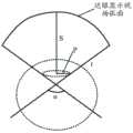
其中,S为所述摄像显示面板的中心到所述用户的瞳孔中心的距离,α为眼睛的最大视角,P为所述用户的瞳孔半径。Wherein, S is the distance from the center of the camera display panel to the center of the pupil of the user, α is the maximum viewing angle of the eye, and P is the radius of the pupil of the user.
可选地,所述近眼显示器还包括:Optionally, the near-eye display further includes:
设置在所述摄像显示面板与所述第一折射结构之间的准直透镜组件,用于将所述多个摄像显示单元的显示部件发出的光线转变为准直光,并输入所述第一折射结构中;A collimating lens assembly disposed between the camera display panel and the first refraction structure is used to convert the light emitted by the display components of the plurality of camera display units into collimated light and input the first in the refracting structure;
所述第一折射结构用于将所述准直透镜组件输入的准直光折射至所述近眼显示器的焦点处。The first refracting structure is used for refracting the collimated light input by the collimating lens assembly to the focal point of the near-eye display.
可选地,所述准直透镜组件包括多个准直透镜,所述多个准直透镜与所述多个摄像显示单元的显示部件一一对应,所述多个准直透镜中的每个准直透镜用于将对应的显示部件发出的光线转变为准直光。Optionally, the collimating lens assembly includes a plurality of collimating lenses, the plurality of collimating lenses are in one-to-one correspondence with the display components of the plurality of camera display units, and each of the plurality of collimating lenses is in a one-to-one correspondence. The collimating lens is used to convert the light emitted by the corresponding display component into collimated light.
可选地,所述多个准直透镜中每两个相邻的准直透镜间隔设置,且所述每两个相邻的准直透镜之间填充有透光的透明基材。Optionally, every two adjacent collimating lenses of the plurality of collimating lenses are arranged at intervals, and a transparent base material that transmits light is filled between each two adjacent collimating lenses.
可选地,每两个相邻的准直透镜之间的间隔与每两个相邻的摄像显示单元之间的间隔正对,即每两个相邻的准直透镜之间的透明基材与每两个相邻的摄像显示单元之间的透明基材正对。这样,外部的实景光线可以无遮挡地通过两者间隔处填充的透明基材进入用户的眼睛。Optionally, the interval between every two adjacent collimating lenses is directly opposite to the interval between every two adjacent camera display units, that is, the transparent substrate between every two adjacent collimating lenses. Opposite to the transparent base material between every two adjacent imaging and display units. In this way, the external real light can enter the user's eyes through the transparent substrate filled in the space between the two without being blocked.
可选地,所述每个摄像显示单元的显示部件包括至少一个发光单元,所述每个准直透镜包括至少一个子准直透镜,所述至少一个子准直透镜与所述至少一个发光单元一一对应,所述至少一个子准直透镜中的每个子准直透镜用于将对应的发光单元发出的光线转变为准直光。Optionally, the display component of each camera display unit includes at least one light-emitting unit, each collimating lens includes at least one sub-collimating lens, and the at least one sub-collimating lens is connected to the at least one light-emitting unit. In a one-to-one correspondence, each sub-collimation lens in the at least one sub-collimation lens is used to convert the light emitted by the corresponding light-emitting unit into collimated light.
可选地,所述第一折射结构包括多个第一子折射结构,所述多个第一子折射结构与所述多个准直透镜一一对应,每个准直透镜位于对应的发光单元与对应的第一子折射结构之间,所述每个准直透镜与对应的发光单元之间通过第三胶水粘接,所述每个准直透镜与对应的第一子折射结构之间通过第四胶水粘接。Optionally, the first refraction structure includes a plurality of first sub-refractive structures, the plurality of first sub-refractive structures are in one-to-one correspondence with the plurality of collimating lenses, and each collimating lens is located in a corresponding light-emitting unit. and the corresponding first sub-refractive structure, each collimating lens and the corresponding light-emitting unit are bonded by a third glue, and between each collimating lens and the corresponding first sub-refractive structure Fourth glue bonding.
可选地,所述每个摄像显示单元中的显示部件包括红色发光单元、绿色发光单元和蓝色发光单元,所述每个准直透镜包括三个子准直透镜,位于同一个显示部件内的所述红色发光单元、所述绿色发光单元和所述蓝色发光单元与位于对应的准直透镜内的三个子准直透镜一一对应。Optionally, the display component in each camera display unit includes a red light-emitting unit, a green light-emitting unit, and a blue light-emitting unit, and each collimating lens includes three sub-collimating lenses, the ones located in the same display component. The red light-emitting unit, the green light-emitting unit, and the blue light-emitting unit are in one-to-one correspondence with the three sub-collimating lenses located in the corresponding collimating lens.
可选地,位于同一显示部件内的所述红色发光单元、所述绿色发光单元和所述蓝色发光单元到各自对应的子准直透镜的最小距离T1分别满足以下关系式:Optionally, the minimum distance T1 from the red light-emitting unit, the green light-emitting unit and the blue light-emitting unit located in the same display component to the respective sub-collimating lenses respectively satisfies the following relational expressions:

其中,Rr、Rg、Rb分别为位于同一显示部件单元内的所述红色发光单元、所述绿色发光单元和所述发光单元各自对应的子准直透镜的曲率半径,nr、ng、nb分别为每个子准直透镜的基材对红色波长的光、绿色波长的光、蓝色波长的光的折射率,nfr、nfg、nfb分别为所述第四胶水对红色波长的光、绿色波长的光、蓝色波长的光的折射率。可选地,同一个准直透镜内相邻的两个子准直透镜之间设置有遮光槽,所述遮光槽内填充吸光材料。Wherein, Rr , Rg , and Rb are respectively the curvature radii of the sub-collimating lenses corresponding to the red light-emitting unit, the green light-emitting unit and the light-emitting unit located in the same display unit unit, nr , ng and nb are the refractive indices of the base material of each sub-collimating lens for red wavelength light, green wavelength light, and blue wavelength light, respectively, and nfr , nfg , and nfb are the fourth glue pair, respectively Refractive index of red wavelength light, green wavelength light, and blue wavelength light. Optionally, a light shielding groove is provided between two adjacent sub-collimating lenses in the same collimating lens, and the light shielding groove is filled with light absorbing material.
可选地,所述摄像显示面板内的每个摄像显示单元的显示部件输出的光线为准直光线。Optionally, the light output by the display component of each imaging display unit in the imaging display panel is a collimated light.
可选地,所述每个摄像显示单元中的摄像部件与显示部件之间设置有遮光层。通过设置遮光层,能够避免显示部件发出的光线照射到感光元件上,从而导致感光元件输出的电信号不准,进而避免了显示部件发出的光线影响摄像部件的成像质量。Optionally, a light shielding layer is provided between the imaging component and the display component in each imaging display unit. By arranging the light shielding layer, the light emitted by the display unit can be prevented from irradiating the photosensitive element, resulting in inaccurate electrical signals output by the photosensitive element, thereby preventing the light emitted by the display unit from affecting the imaging quality of the imaging unit.
第二方面,提供了一种近眼显示系统,该近眼显示系统包括:In a second aspect, a near-eye display system is provided, and the near-eye display system includes:
如第一方面或第一方面的上述任一种可能的实现方式所述的近眼显示器、收发信机、控制芯片和电池;The near-eye display, transceiver, control chip and battery according to the first aspect or any one of the possible implementation manners of the first aspect;
所述近眼显示器用于将来自被摄对象的光线转换为电信号,并在所述控制芯片的控制下显示图像,将显示的图像投射到用户的眼睛内;The near-eye display is used for converting the light from the subject into electrical signals, displaying images under the control of the control chip, and projecting the displayed images into the eyes of the user;
所述控制芯片用于根据所述收发信机接收到的第一数字图像信号,驱动所述近眼显示器的显示部件显示相应的图像,并将所述近眼显示器得到被摄对象的图像的电信号转换为第二数字图像信号;The control chip is used to drive the display component of the near-eye display to display a corresponding image according to the first digital image signal received by the transceiver, and convert the electrical signal of the image of the subject obtained by the near-eye display into the electrical signal is the second digital image signal;
所述收发信机用于接收所述第一数字图像信号,并将所述第一数字图像信号传送给所述控制芯片,还用于从所述控制芯片获取第二数字图像信号,并将所述第二数字图像信号发送给终端设备;The transceiver is used for receiving the first digital image signal and transmitting the first digital image signal to the control chip, and is also used for acquiring the second digital image signal from the control chip, and transmitting the first digital image signal to the control chip. sending the second digital image signal to the terminal device;
电池,用于为所述近眼显示系统提供电源。a battery for providing power for the near-eye display system.
本发明实施例的近眼显示系统,不仅能够实现近眼显示,还能够提供较大的视场范围,提升用户的视觉体验,还能够同时实现摄像“所见即所得”。The near-eye display system of the embodiment of the present invention can not only realize near-eye display, but also can provide a larger field of view, improve the user's visual experience, and can simultaneously realize the "what you see is what you get" camera.
在一些可能的实现方式中,终端设备接收到第二数字图像信号之后,可以根据第二数字图像信号在显示屏上呈现近眼显示器拍摄的照片或视频。In some possible implementations, after receiving the second digital image signal, the terminal device may present a photo or video shot by the near-eye display on the display screen according to the second digital image signal.
所述第一数字图像信号可以是由与近眼显示器建立连接(如有线连接或无线连接)的终端或服务器发送的。The first digital image signal may be sent by a terminal or a server that establishes a connection (such as a wired connection or a wireless connection) with the near-eye display.
所述控制芯片可以将接收到的所述第一数字图像信号转换为所述近眼显示器中摄像显示单元的驱动电流强弱及时序信号,然后根据所述驱动电流强弱及时序信号驱动所述近眼显示器的显示部件进行图像呈现。The control chip can convert the received first digital image signal into a driving current strength and timing signal of the camera display unit in the near-eye display, and then drive the near-eye according to the driving current strength and timing signal. The display part of the display performs image presentation.
在一些实施例中,第一数字图像信号和第二数字图像信号相同,此时近眼显示器中的显示部件显示的图像与摄像部件拍摄到的图像相同。In some embodiments, the first digital image signal and the second digital image signal are the same, and the image displayed by the display part in the near-eye display is the same as the image captured by the camera part.
在一些实施例中,第一数字图像信号和第二数字图像信号不同,此时近眼显示器中的显示部件显示的图像与摄像部件拍摄到的图像不同。In some embodiments, the first digital image signal and the second digital image signal are different, and the image displayed by the display part in the near-eye display is different from the image captured by the camera part.
在一种可能的实现方式中,所述近眼显示系统包括一个所述近眼显示器。用户佩戴所述近眼显示系统时,所述近眼显示器对应于用户的左眼或右眼。In a possible implementation, the near-eye display system includes one of the near-eye displays. When a user wears the near-eye display system, the near-eye display corresponds to the user's left eye or right eye.
在一种可能的实现方式中,所述近眼显示系统包括两个所述近眼显示器。用户佩戴所述近眼显示系统时,一个所述近眼显示器对应于用户的左眼,一个所述近眼显示器对应于用户的右眼。In a possible implementation manner, the near-eye display system includes two of the near-eye displays. When the user wears the near-eye display system, one near-eye display corresponds to the user's left eye, and one near-eye display corresponds to the user's right eye.
在一种可能的实现方式中,所述收发信机为无线收发信机。In a possible implementation manner, the transceiver is a wireless transceiver.
在一种可能的实现方式中,所述近眼显示系统还包括促动器,所述促动器用于支撑所述近眼显示器,并根据所述用户的眼球的运动轨迹,调整所述近眼显示器的位置,使得所述近眼显示器的焦点落在所述用户的眼球内。这样,当用户的眼球发生转动时,用户无需手动调整近眼显示器即可看到清晰的图像,能够提升用户的使用体验。In a possible implementation manner, the near-eye display system further includes an actuator, where the actuator is used to support the near-eye display and adjust the position of the near-eye display according to the movement trajectory of the user's eyeballs , so that the focus of the near-eye display falls within the user's eyeball. In this way, when the user's eyeball rotates, the user can see a clear image without manually adjusting the near-eye display, which can improve the user's experience.
附图说明Description of drawings
图1是采用AR技术呈现的效果图;Figure 1 is the rendering of AR technology;
图2是根据本发明实施例的近眼显示系统的示意图;2 is a schematic diagram of a near-eye display system according to an embodiment of the present invention;
图3是根据本发明实施例的近眼显示器的侧视图;3 is a side view of a near-eye display according to an embodiment of the present invention;
图4是根据本发明另一实施例的近眼显示器的侧视图;4 is a side view of a near-eye display according to another embodiment of the present invention;
图5是根据本发明另一实施例的近眼显示器的侧视图;5 is a side view of a near-eye display according to another embodiment of the present invention;
图6是根据本发明另一实施例的近眼显示器的侧视图;6 is a side view of a near-eye display according to another embodiment of the present invention;
图7是根据本发明另一实施例的近眼显示器中的显示部件的侧视图;7 is a side view of a display component in a near-eye display according to another embodiment of the present invention;
图8是根据本发明实施例的近眼显示器中的摄像显示单元的顶视图;8 is a top view of a camera display unit in a near-eye display according to an embodiment of the present invention;
图9是根据本发明另一实施例的折射结构的参数示意图;FIG. 9 is a schematic parameter diagram of a refraction structure according to another embodiment of the present invention;
图10是根据本发明另一实施例的折射结构的侧视图;10 is a side view of a refractive structure according to another embodiment of the present invention;
图11是近眼显示视场弧面的示意图;11 is a schematic diagram of a near-eye display field of view arc;
图12是根据本发明另一实施例的近眼显示器的侧视图;12 is a side view of a near-eye display according to another embodiment of the present invention;
图13是根据本发明另一实施例的近眼显示器的侧视图;13 is a side view of a near-eye display according to another embodiment of the present invention;
图14是根据本发明另一实施例的近眼显示器中的准直滤镜的侧视图;14 is a side view of a collimating filter in a near-eye display according to another embodiment of the present invention;
图15是根据本发明另一实施例的近眼显示器的原理示意图;15 is a schematic diagram of the principle of a near-eye display according to another embodiment of the present invention;
图16是根据本发明另一实施例的近眼显示器的尺寸示意图;16 is a schematic view of the size of a near-eye display according to another embodiment of the present invention;
图17是根据本发明实施例的近眼显示器的摄像显示单元的排列示意图;17 is a schematic diagram of an arrangement of a camera display unit of a near-eye display according to an embodiment of the present invention;
图18是根据本发明实施例的近眼显示器的摄像显示单元的另一排列示意图;18 is another schematic diagram of the arrangement of the camera display unit of the near-eye display according to an embodiment of the present invention;
图19是根据本发明实施例的准直滤镜的制作工艺流程图。FIG. 19 is a flow chart of a manufacturing process of a collimating filter according to an embodiment of the present invention.
具体实施方式Detailed ways
下面将结合附图,对本发明实施例中的技术方案进行描述。The technical solutions in the embodiments of the present invention will be described below with reference to the accompanying drawings.
图2是根据本发明实施例的近眼显示系统的示意图。如图2所示,近眼显示系统包括:近眼显示器、控制芯片、电池、收发信机和天线。FIG. 2 is a schematic diagram of a near-eye display system according to an embodiment of the present invention. As shown in Figure 2, the near-eye display system includes: a near-eye display, a control chip, a battery, a transceiver and an antenna.
近眼显示器用于将图像投射到用户的眼睛内,并实现对外部图像的采集功能。控制芯片用于将数字图像信号转化为近眼显示器的显示部件的驱动电流强弱及时序信号,并通过隐藏在镜框内的金属连线连接到近眼显示器,驱动近眼显示器的显示部件进行图像呈现;同时将近眼显示器的摄像部件采集到的图像的电信号转化为数字图像信号。电池为整个近眼显示系统提供电源。收发信机及天线用于从移动终端接收通过无线链路传输的数字图像信号,并传送给控制芯片;同时从控制芯片获取摄像部件采集到的图像的数字图像信号,发送给终端设备。其中,可选地,该收发信机具体可以是无线收发信机。The near-eye display is used to project the image into the user's eyes and realize the function of collecting external images. The control chip is used to convert the digital image signal into the driving current strength and timing signal of the display component of the near-eye display, and is connected to the near-eye display through the metal connection hidden in the frame to drive the display component of the near-eye display for image presentation; The electrical signal of the image collected by the imaging component of the near-eye display is converted into a digital image signal. The battery provides power for the entire near-eye display system. The transceiver and the antenna are used to receive the digital image signal transmitted by the wireless link from the mobile terminal and transmit it to the control chip; meanwhile, the digital image signal of the image collected by the camera unit is obtained from the control chip and sent to the terminal device. Wherein, optionally, the transceiver may specifically be a wireless transceiver.
如图2所示,近眼显示系统可以包括两个近眼显示器,左侧近眼显示器和右侧近眼显示器,该两个近眼显示器分别对应于用户的左眼和右眼,这样用户的双眼都可以看到采用AR显示技术的增强实景图像。但本发明实施例对此并不限定,近眼显示系统还可以只包括一个近眼显示器,该近眼显示器对应于用户的左眼或右眼,这样用户对应于近眼显示器的眼睛可以看到采用AR显示技术的增强实景图像或采用VR显示技术的立体视觉图像。As shown in FIG. 2 , the near-eye display system may include two near-eye displays, a left near-eye display and a right near-eye display, the two near-eye displays respectively correspond to the user's left eye and right eye, so that both eyes of the user can see Augmented reality images with AR display technology. However, the embodiment of the present invention is not limited to this. The near-eye display system may also include only one near-eye display, and the near-eye display corresponds to the user's left eye or right eye, so that the user's eyes corresponding to the near-eye display can see the AR display technology. augmented reality images or stereoscopic images using VR display technology.
也就是说,本发明实施例中的近眼显示器可以看作是近眼显示系统中的一个镜片。That is to say, the near-eye display in the embodiment of the present invention can be regarded as a lens in the near-eye display system.
需要说明的是,本发明实施例中的控制芯片也可以称为驱动芯片。It should be noted that, the control chip in the embodiment of the present invention may also be referred to as a driver chip.
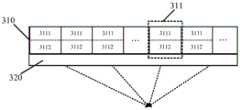
如图3所示,本发明实施例提供的近眼显示器可以包括摄像显示面板310和第一折射结构320。其中摄像显示面板310包括平铺设置的多个摄像显示单元311。其中,每个摄像显示单元311包括沿所述摄像显示面板310的厚度方向叠加的摄像部件3111和显示部件3112,摄像部件3111位于显示部件3112的背面。As shown in FIG. 3 , the near-eye display provided by the embodiment of the present invention may include a
应理解,显示部件3112的背面与显示部件3112的表面正对。显示部件3112的表面能够发光,通过控制摄像显示面板310上的多个摄像显示单元311的显示部件3112的发光,能够显示图像。It should be understood that the rear surface of the
该多个摄像显示单元311平铺设置在摄像显示面板310内,具体是指:该多个摄像显示单元311在垂直于摄像显示面板310的方向上互不重叠,每个摄像显示单元311在垂直于摄像显示面板310的方向上不会对其他摄像显示单元311输出的光线造成遮挡。The plurality of imaging and
每个摄像部件3111用于拍摄照片或视频,每个显示部件3112用于显示图像。具体的,每个摄像部件3111用于接收来自被摄对象的光线,并将来自被摄对象的光线进行光电转换生成电信号。每个显示部件3112用于发光,通过控制摄像显示面板310内的多个摄像显示单元311的显示部件3112的发光,摄像显示面板310的显示部件3112的表面可以显示图像。Each
第一折射结构320设置在摄像显示面板310的发光侧(即显示部件3112的表面),用于将摄像显示面板310输出的光线折射到近眼显示器的焦点处,近眼显示器的焦点落在用户的眼球内。The
具体地,每个摄像显示单元311的显示部件输出的光线组成光柱,该光柱经过第一折射结构320折射后光柱的中心指向近眼显示器的焦点处。Specifically, the light output from the display component of each
需要说明的是,近眼显示器的焦点是指准直光经过该近眼显示器之后被汇聚到的一个点,这个点即为该近眼显示器的焦点。所谓的准直光是相对于发散光来说的,通常光线是发散的,即开始相邻的两条光线传播后会相离越来越远。光线自光源处发出后,出射光锥的发散角小于或等于特定的角度(例如,在本发明实施例中,该特定角度可以小于或等于5°),则可认为该光源发出的多条光线互相平行,为准直光。准直光通俗说就是多条光线之间大致是平行的。It should be noted that the focus of the near-eye display refers to a point where the collimated light is converged after passing through the near-eye display, and this point is the focus of the near-eye display. The so-called collimated light is relative to the divergent light, usually the light is divergent, that is, the two adjacent light rays will be farther and farther apart after they start to propagate. After the light is emitted from the light source, the divergence angle of the outgoing light cone is less than or equal to a specific angle (for example, in this embodiment of the present invention, the specific angle may be less than or equal to 5°), then it can be considered that the light source emits multiple rays of light parallel to each other for collimated light. Collimated light is generally said to be roughly parallel between multiple rays.
在本发明实施例中,近眼显示器包括摄像显示面板和第一折射结构,所以在本发明实施例中,摄像显示面板的显示部件输出的光线是经过第一折射结构之后,被折射到该近眼显示器的焦点处的。此外,本领域技术人员都知道,为了让用户能够更清楚地看清近眼显示器显示的图像,可选地,近眼显示器的焦点会落在用户的眼球中。具体地,近眼显示器的焦点落在用户的瞳孔圆心的中轴线上。本实施例及其他实施例中,如无特殊说明,近眼显示器的焦点也均落在用户的瞳孔圆心的中轴线上。还需要说明的是,用户佩戴近眼显示器之后,如果用户的眼球发生了转动,则近眼显示器的焦点可能无法落在用户的瞳孔的圆心的中轴线上,此时可以由用于支撑近眼显示器的器件(如促动器)自动跟踪用户的眼球转动,并自动调整近眼显示器的位置,使得近眼显示器的焦点落在用户的瞳孔的圆心的中轴线上。这样,当用户的眼球发生转动时,用户无需手动调整近眼显示器即可看到清晰的图像,能够提升用户的使用体验。In the embodiment of the present invention, the near-eye display includes an imaging display panel and a first refraction structure, so in the embodiment of the present invention, the light output by the display component of the imaging display panel is refracted to the near-eye display after passing through the first refraction structure of focus. In addition, those skilled in the art know that, in order to allow the user to see the image displayed by the near-eye display more clearly, optionally, the focus of the near-eye display will fall on the user's eyeball. Specifically, the focal point of the near-eye display falls on the central axis of the center of the pupil of the user. In this embodiment and other embodiments, unless otherwise specified, the focus of the near-eye display also falls on the central axis of the center of the pupil of the user. It should also be noted that after the user wears the near-eye display, if the user's eyeball rotates, the focus of the near-eye display may not be able to fall on the central axis of the center of the user's pupil. (eg, an actuator) automatically tracks the user's eyeball rotation, and automatically adjusts the position of the near-eye display so that the focus of the near-eye display falls on the central axis of the center of the user's pupil. In this way, when the user's eyeball rotates, the user can see a clear image without manually adjusting the near-eye display, which can improve the user's experience.
使用促动器等支撑部件调整该近眼显示器的位置时,还可以结合用户的头型或脸型等进行调整,这样能够更加精确地调整该近眼显示器的位置。When adjusting the position of the near-eye display using a supporting member such as an actuator, the adjustment can also be performed in combination with the user's head shape or face shape, etc., so that the position of the near-eye display can be adjusted more accurately.
可选地,第一折射结构320的基材可以为透明基材。Optionally, the substrate of the
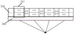
可选地,如图4所示,多个摄像显示单元311中的每两个相邻摄像显示单元311间隔设置,且每两个相邻摄像显示单元311之间填充有透光的透明基材。这样的设计能够使得外部实景光线透过相邻摄像显示单元之间的透明基材进入用户的眼睛。而且,将多个摄像显示单元的显示部件平铺设置在整个近眼显示器上,还能够提供较大的视场范围,进而能够提升用户的视觉体验。Optionally, as shown in FIG. 4 , every two adjacent
还需要说明的是,第一折射结构320中与每两个摄像显示单元311之间间隔的透明基材正对的部分允许外界光线无畸变通过。可选地,第一折射结构320中与每两个摄像显示单元311之间间隔的透明基材正对的部分也可以为透明基材。It should also be noted that, the portion of the
可选地,摄像显示面板310还可以包括透明基板,多个摄像显示单元311可以间隔放置在摄像显示面板310的透明基板上。Optionally, the
通过在摄像显示面板上设置多个摄像显示单元,并且在任意两个相邻摄像显示单元之间的间隔处采用透明基材,使得外部实景光线能够通过任意两个摄像显示单元之间的间隔,从而实现外部实景图像与摄像显示单元显示的图像的叠加。By arranging a plurality of camera display units on the camera display panel, and using a transparent substrate at the interval between any two adjacent camera display units, the external real scene light can pass through the interval between any two camera display units, Thereby, the superposition of the external real scene image and the image displayed by the camera display unit is realized.
本发明实施例中的透明基材可以是玻璃或透明性树脂,但本发明实施例对此并不限定,该透明基材还可以是其他能够透光的材料。需要说明的是,本发明实施例对透明基材的透光率也不做限定,例如,该透明基材的透光率可以为80%~95%。透明基材的透光率越高,人们佩戴近眼显示器时看到的图像的质量越高。可选地,透明基材覆盖任意两个相邻摄像显示单元之间的全部间隔,从而最大可能提升透光率。The transparent substrate in the embodiment of the present invention may be glass or transparent resin, but the embodiment of the present invention is not limited thereto, and the transparent substrate may also be other materials that can transmit light. It should be noted that the embodiment of the present invention does not limit the light transmittance of the transparent substrate, for example, the light transmittance of the transparent substrate may be 80% to 95%. The higher the light transmittance of the transparent substrate, the higher the quality of the image people see when wearing a near-eye display. Optionally, the transparent substrate covers the entire interval between any two adjacent camera display units, so as to maximize the light transmittance.
在一些实施例中,多个摄像显示单元311可以布置为M行×N列的矩阵形状,M和N均为大于或等于1的整数。但本发明实施例对此并不限定,多个摄像显示单元311还可以布置为其他规则形状或不规则形状。In some embodiments, the plurality of
相邻摄像显示单元可以指在一个或多个指定方向上相邻的摄像显示单元,该指定方向可以根据摄像显示单元的布置形状确定。例如,多个摄像显示单元311布置为矩阵形状,相邻摄像显示单元指的是在行方向和/或列方向上相邻的摄像显示单元。Adjacent imaging and display units may refer to imaging and display units that are adjacent in one or more specified directions, and the specified directions may be determined according to the arrangement shape of the imaging and display units. For example, a plurality of image
应理解,每两个相邻摄像显示单元间隔设置是指设置的两个相邻摄像显示单元之间存在一定的间隔距离,该间隔距离可以根据实际的产品进行调整。间隔距离越大,透光率越高,但是图像质量越差。间隔距离越小,透光率越低,图像质量越高。It should be understood that every two adjacent camera display units are arranged at intervals, which means that there is a certain distance between the two adjacent camera display units, and the distance can be adjusted according to actual products. The larger the separation distance, the higher the light transmittance, but the worse the image quality. The smaller the separation distance, the lower the light transmittance and the higher the image quality.
在一些实施例中,每两个相邻摄像显示单元之间的间隔距离相同,这样有利于简化近眼显示器的生产工艺。但本发明实施例对此并不限定,每两个相邻摄像显示单元之间的间隔距离也可以不同,或者部分相邻摄像显示单元之间的间隔距离相同。例如,多个摄像显示单元311布置为矩阵形状,在行方向和/或列方向上相邻的两个摄像显示单元之间的间隔距离相同;或者,在行方向上相邻的两个摄像显示单元之间间隔第一距离,在列方向上相邻的两个摄像显示单元之间间隔第二距离,且第一距离与第二距离不同。In some embodiments, the separation distance between every two adjacent camera display units is the same, which is beneficial to simplify the production process of the near-eye display. However, the embodiment of the present invention is not limited to this, and the separation distance between every two adjacent camera display units may also be different, or the separation distance between some adjacent camera display units may be the same. For example, the plurality of imaging and
由于人眼视觉对视黄斑部分的分辨率高,而对边缘部分的分辨率较低,因此在一些实施例中,还可以根据摄像显示单元距离摄像显示面板中心(即近眼显示器镜片中心)的距离来设置摄像显示单元之间的间隔距离。例如距离摄像显示面板中心越远,摄像显示单元之间的间隔越大,这样并不会影响用户的视觉体验。Since human vision has high resolution on the macular part and low resolution on the edge part, in some embodiments, the distance between the camera display unit and the center of the camera display panel (that is, the center of the near-eye display lens) can also be determined according to the to set the separation distance between the camera display units. For example, the farther from the center of the camera display panel, the greater the interval between the camera display units, which will not affect the user's visual experience.
本发明实施例的近眼显示器中,通过在摄像显示面板的发光侧设置折射结构,将摄像显示面板的显示部件显示的图像折射到用户的眼睛内,同时外界的实景光线穿过摄像显示单元之间的透明基材进入用户的眼睛,能够实现摄像显示面板显示的虚拟图像与外部实景图像叠加的AR显示。同时,将摄像显示单元排列在整个摄像显示面板上,这样能够提供较大的视场范围,进而能够提升用户的视觉体验。In the near-eye display of the embodiment of the present invention, by disposing a refracting structure on the light-emitting side of the camera display panel, the image displayed by the display part of the camera display panel is refracted into the user's eyes, and at the same time, the real light from the outside world passes between the camera display units. The transparent substrate can enter the user's eyes, which can realize AR display in which the virtual image displayed on the camera display panel is superimposed with the external real image. At the same time, the camera display units are arranged on the entire camera display panel, which can provide a larger field of view, thereby improving the user's visual experience.
进一步地,通过将显示部件和摄像部件集成为摄像显示单元,在实现AR显示的同时还可以实现摄像功能,且摄像视角与人眼视角一致,即实现AR摄像“所见即所得”。同时,由于近眼显示器无需额外配置摄像装置,有利于降低具有摄像功能和AR显示功能的近眼显示器的成本、重量和体积。Further, by integrating the display component and the camera component into a camera display unit, the camera function can also be realized while the AR display is realized, and the camera view angle is consistent with the human eye view angle, that is, AR camera "what you see is what you get". At the same time, since the near-eye display does not need to be equipped with an additional camera device, it is beneficial to reduce the cost, weight and volume of the near-eye display with the camera function and AR display function.
另外,由于本发明实施例的近眼显示器没有复杂的光学透镜组和机电运动部件,因此有利于减轻近眼显示器的重量。In addition, since the near-eye display of the embodiment of the present invention does not have complex optical lens groups and electromechanical moving parts, it is beneficial to reduce the weight of the near-eye display.
本发明实施例中的折射结构可以为任意能够将摄像显示单元的显示部件输出的光线折射至近眼显示器的焦点处的结构,本发明实施例对折射结构的具体实现形式不作限定。The refraction structure in the embodiment of the present invention may be any structure capable of refracting the light output by the display component of the imaging display unit to the focal point of the near-eye display, and the specific implementation form of the refraction structure is not limited in the embodiment of the present invention.
可选地,如图5所示,近眼显示器还可以包括:设置在摄像显示面板310的摄像部件3111的表面的第二折射结构330,第二折射结构330用于将输入的来自被摄对象的光线折射到每个摄像显示单元311的摄像部件3111中。Optionally, as shown in FIG. 5 , the near-eye display may further include: a
其中,来自被摄对象的光线包括被摄对象反射的光线和被摄对象发出的光线。The light from the subject includes the light reflected by the subject and the light emitted by the subject.
通过在摄像显示面板的摄像部件的表面设置第二折射结构,能够筛选进入摄像部件的入射光线光路,有利于使得近眼显示器上的摄像部件具备与人眼相当的入射光线光路,进而能够对外界的被摄对象成像。By arranging the second refraction structure on the surface of the imaging component of the imaging display panel, the optical path of the incident light entering the imaging component can be screened, which is beneficial to enable the imaging component on the near-eye display to have an incident light optical path equivalent to that of the human eye, and thus be able to detect the incident light path of the outside world. The subject is imaged.
可选地,第一折射结构320的入射光线的光路与第二折射结构330的出射光线的光路相同。Optionally, the optical path of the incident light of the
这样使得近眼显示器上的摄像部件具备与用户的眼睛相当的入射光线光路,即摄像部件的视角与用户的视角相同,可以实现用户所见与摄像部件所拍摄的图像相同。In this way, the imaging component on the near-eye display has an incident light path equivalent to that of the user's eyes, that is, the viewing angle of the imaging component is the same as the user's viewing angle, so that what the user sees is the same as the image captured by the imaging component.
需要说明的是,本发明实施例对此并不限定,第一折射结构320的入射光线的光路和第二折射结构330的出射光线的光路也可以不同,此时摄像部件的视角与用户的视角不同。It should be noted that this embodiment of the present invention is not limited to this. The optical path of the incident light of the
可选地,第一折射结构320和第二折射结构330的结构相同。由于光路具有可逆性,采用结构相同的两个折射结构,可以使得一个折射结构的入射光线的光路与另一个折射结构的出射光线的光路相同。需要说明的是,本发明实施例对此并不限定,第一折射结构320和第二折射结构330的结构也可以不同。Optionally, the structures of the
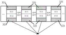
在一些实施例中,如图6所示,第一折射结构包括多个第一子折射结构321。多个第一子折射结构321与多个摄像显示单元311的显示部件3112一一对应,其中每个第一子折射结构321用于将对应的显示部件3112输出的光线折射至近眼显示器的焦点处。每两个相邻的子折射结构321之间填充有透光的透明基材。该透明基材能够使得外部实景光线通过。可选地,相邻的第一子折射结构321之间填充的透明基材与相邻的摄像显示单元311之间填充的透明基材相同。In some embodiments, as shown in FIG. 6 , the first refractive structure includes a plurality of first
可选地,每个第一子折射结构321与对应的摄像显示单元311之间通过胶水粘接。Optionally, each first
可选地,每个第一子折射结构321上靠近对应的显示部件3112的一侧的表面大于或等于对应的显示部件3112的发光表面。这样能够使得每个显示部件3112发出的光线更多地进入对应的第一子折射结构321中,进而使得每个第一子折射结构321能够将更多的光线折射至近眼显示器的焦点处。Optionally, the surface of the side of each first
可选地,每两个相邻的第一子折射结构321之间的距离与其对应的两个相邻摄像显示单元311之间的距离相同。可选地,每个第一子折射结构321与对应的摄像显示单元311的中心轴重合。Optionally, the distance between every two adjacent first
在一些实施例中,可以将通过胶水粘接的每个摄像显示单元311和对应的第一子折射结构321作为一个像素组件。也就是说,近眼显示器可以包括间隔设置多个该像素组件,且每两个相邻像素组件之间填充有透光的透明基材。外部实景光线能够透过该透明基材进入用户的眼睛。In some embodiments, each
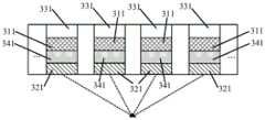
可选地,如图6所示,第二折射结构包括多个第二子折射结构331,多个第二子折射结构331与多个摄像显示单元311的摄像部件3111一一对应。其中每个第二子折射结构331用于将来自被摄对象的光线折射到对应的摄像部件3111中,多个第二子折射结构331中的每两个相邻的第二子折射结构331间隔设置,且每两个相邻的第二子折射结构331之间填充有透光的透明基材。Optionally, as shown in FIG. 6 , the second refraction structure includes a plurality of second
可选地,每个第二子折射结构331与对应的摄像显示单元311之间通过胶水粘接。Optionally, each second
可选地,每个第二子折射结构331上靠近对应的摄像显示单元311的一侧的表面大于或等于对应的摄像部件3111的表面,这样能够将更多的光线折射至摄像显示单元311的摄像部件3111中。Optionally, the surface of each second
可选地,每两个相邻的第二子折射结构331之间的距离与其对应的两个相邻摄像显示单元311之间的距离相同。可选地,每个第二子折射结构331与对应的摄像显示单元311的中心轴重合。Optionally, the distance between every two adjacent second
在一些实施例中,可以将通过胶水粘接的每个摄像显示单元311、对应的第一子折射结构321和对应的第二子折射结构331作为一个像素组件。也就是说,近眼显示器可以包括间隔设置的多个该像素组件,且每两个相邻像素组件之间填充有透光的透明基材。外部实景光线能够透过该透明基材进入用户的眼睛。In some embodiments, each
在一些实施例中,摄像显示单元311的显示部件3112是单色发光单元,例如每个摄像显示单元311的显示部件包括一种颜色的发光单元,如红色发光单元、绿色发光单元或蓝色发光单元。In some embodiments, the
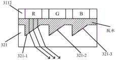
在一些实施例中,每个摄像显示单元311的显示部件3112包括多种颜色的发光单元,例如显示部件3112可以包括红色(R)发光单元、绿色(G)发光单元和蓝色(B)发光单元,如图7所示。如图8所示为每个摄像显示单元的顶视图。应理解,图8所示仅以每个摄像显示单元的顶视图为圆形为例,但本发明实施例对此并不限定。In some embodiments, the
在一些实施例中,如图7所示,每个第一子折射结构321上靠近对应的摄像显示面板的显示部件3112的一侧设置有三个第一斜槽321-1~321-3,每个第一子折射结构321中的三个第一斜槽321-1~321-3与每个摄像显示单元311的显示部件3112中的三个发光单元一一对应,每个第一斜槽用于将对应的发光单元输出的光线折射至近眼显示器的焦点处。用于粘接每个摄像显示单元的显示部件3112和对应的子折射结构321的胶水如图7所示斜线阴影部分。In some embodiments, as shown in FIG. 7 , each of the first
需要说明的是,图7中仅以每个发光单元发出的光为准直光为例,显示部件3112中的每个发光单元发出的光还可以为发散光,本发明实施例对此并不限定。还需要说明的是,图7所示仅以发光单元输出的三条光线为例描述近眼显示器的光路。实际上,每个发光单元输出的多条光线组成的光束经过同一个第一斜槽折射后指向近眼显示器的焦点。具体地,每个发光单元输出的多条光线组成的光束经过第一斜槽折射,折射后光束的中心指向近眼显示器的焦点处。发光单元输出的光束的横截面的尺寸与发光单元的尺寸相关。It should be noted that in FIG. 7 only the light emitted by each light-emitting unit is taken as an example of collimated light, the light emitted by each light-emitting unit in the
当每个摄像显示单元311的显示部件3112包括红色发光单元、绿色发光单元和蓝色发光单元时,摄像显示单元311的显示部件3112能够输出不同颜色的光,使得LCD面板能够实现彩色显示,进而使得近眼显示器能够显示彩色图像。When the
本发明实施例中的发光单元可以是发光二极管(Light-Emitting Diode,LED),或有机发光二极管(Organic Light-Emitting Diode,OLED)。The light-emitting unit in the embodiment of the present invention may be a light-emitting diode (Light-Emitting Diode, LED), or an organic light-emitting diode (Organic Light-Emitting Diode, OLED).
为了使得每个第一折射结构能够更加精准地将每个摄像显示单元的显示部件3112输出的光线折射至近眼显示器的焦点处,每个第一子折射结构321上的每个第一斜槽的设计可以满足如下要求:In order for each first refraction structure to more accurately refract the light output by the
1、每个第一斜槽的斜面所在的平面与第一子折射结构321上远离摄像显示面板的一侧表面所在的平面具有一交线,交线与第一子折射结构321上远离摄像显示面板的一侧表面上沿近眼显示器的水平方向的第一中轴线之间的第一夹角Φ(如图9所示)满足以下关系式(1):1. The plane on which the inclined surface of each first inclined groove is located and the plane on the side of the first

其中,该交线与第一中轴线之间的第二夹角大于或等于第一夹角,即第一夹角为该交线与第一中轴线形成的两个夹角中较小的一个夹角;Wherein, the second included angle between the intersection line and the first central axis is greater than or equal to the first included angle, that is, the first included angle is the smaller of the two included angles formed by the intersection line and the first central axis included angle;
2、每个第一斜槽的斜面所在的平面与第一折射结构321上远离摄像显示面板的一侧表面所在的平面之间的第三夹角θ(如图10所示)满足以下关系式(2):2. The third included angle θ (as shown in FIG. 10 ) between the plane on which the inclined surface of each first inclined groove is located and the plane on the side of the


其中,每个第一斜槽的斜面所在的平面与第一子折射结构321上远离摄像显示面板310的一侧表面所在的平面之间的第四夹角大于或等于第三夹角,即第三夹角为每个斜槽的斜面与子折射结构321上远离摄像显示面板310的一侧表面形成的两个夹角中较小的一个夹角。Wherein, the fourth included angle between the plane where the inclined surface of each first inclined groove is located and the plane where the side surface of the first
关系式(1)和关系式(2)中各个参数的含义如下所示:The meaning of each parameter in relational formula (1) and relational formula (2) is as follows:
D为每个第一斜槽的斜面的中心点到该第一中轴线的距离,L为每个第一斜槽的斜面的中心点到第一子折射结构321上远离摄像显示面板310的一侧表面上沿近眼显示器的垂直方向(如y方向)的第二中轴线的距离,n为子折射结构321的基材的折射率,nf为第一子折射结构321与对应的显示部件3112之间的胶水的折射率,r为近眼显示视场弧面曲率半径。D is the distance from the center point of the inclined surface of each first inclined groove to the first central axis, L is the distance from the center point of the inclined surface of each first inclined groove to a distance on the first
在一些实施例中,近眼显示视场弧面曲率半径r满足以下关系式(3):In some embodiments, the near-eye display field of view arc surface curvature radius r satisfies the following relationship (3):

其中,S为摄像显示面板的中心到用户的瞳孔中心的距离,α为眼睛的最大视角,P为用户的瞳孔半径,如图11所示。用户的瞳孔半径指的是:用户的眼球转动情况下瞳孔可以覆盖的眼球表面的曲面面积在水平面投影的半径。Among them, S is the distance from the center of the camera display panel to the center of the user's pupil, α is the maximum viewing angle of the eye, and P is the radius of the user's pupil, as shown in FIG. 11 . The pupil radius of the user refers to the radius of the projection on the horizontal plane of the curved surface area of the eyeball surface that the pupil can cover when the user's eyeball rotates.
近眼显示视场弧面的球心即为近眼显示器的第一折射结构的焦点。The spherical center of the arc surface of the near-eye display field of view is the focal point of the first refraction structure of the near-eye display.
满足以上设计的折射结构,能够使摄像显示面板在用户的视网膜的成像更加清晰,成像不会因用户的眼睛变焦而模糊。需要说明的是,以上描述的关系式(1)和关系式(2)的例子是为了帮助本领域技术人员更好地理解本发明实施例,而非要限制本发明实施例的范围。本领域技术人员根据所给出的关系式(1)和关系式(2)的例子,显然可以进行各种等价的修改或变化,这样的修改或变化也落入本发明实施例的范围内。The refraction structure satisfying the above design can make the imaging of the imaging display panel on the retina of the user clearer, and the imaging will not be blurred due to the zooming of the user's eyes. It should be noted that the examples of relational formula (1) and relational formula (2) described above are for helping those skilled in the art to better understand the embodiments of the present invention, but are not intended to limit the scope of the embodiments of the present invention. Those skilled in the art can obviously make various equivalent modifications or changes according to the examples of relational formula (1) and relational formula (2) given, and such modifications or changes also fall within the scope of the embodiments of the present invention .
在一些实施例中,第二子折射结构331的结构与第一子折射结构321的结构相同,这里不再赘述。In some embodiments, the structure of the second
在一些实施例中,为了使得发光单元发出的光线尽可能多地入射至第一折射结构,进而使得第一折射结构将尽可能多的光线折射至近眼显示器的焦点处,可以使发光单元发出的光线为准直光(即平行光)。例如,可以使用能够发出准直光的LED,如图7所示,显示部件3112中每个发光单元发出的光为准直光。In some embodiments, in order to make the light emitted by the light emitting unit enter the first refraction structure as much as possible, so that the first refraction structure refracts as much light as possible to the focal point of the near-eye display, the light emitted by the light emitting unit may be Light is collimated (ie, parallel light). For example, an LED capable of emitting collimated light may be used, and as shown in FIG. 7 , the light emitted by each light emitting unit in the
或者,还可以使用准直透镜,对发光单元发出的发散光线进行准直处理。在一些实施例中,近眼显示器还可以包括设置在摄像显示面板310与第一折射结构320之间的准直透镜组件,用于将多个显示部件3112发出的光线转变为准直光,并输入第一折射结构320中。相应地,第一折射结构320用于将准直透镜组件输入的准直光折射至近眼显示器的焦点处。Alternatively, a collimating lens can also be used to perform collimation processing on the divergent light emitted by the light-emitting unit. In some embodiments, the near-eye display may further include a collimating lens assembly disposed between the
在一些实施例中,如图12所示,准直透镜组件包括多个准直透镜341,多个准直透镜341与多个摄像显示单元311一一对应,每个准直透镜341用于将对应的摄像显示单元311的显示部件3112发出的光线转变为准直光。每两个相邻的准直透镜341间隔设置,且每两个相邻的准直透镜341之间填充有透光的透明基材。可选地,相邻的准直透镜341之间填充的透明基材与相邻的摄像显示单元311之间填充的透明基材相同。In some embodiments, as shown in FIG. 12 , the collimating lens assembly includes a plurality of
在一些实施例中,如图12所示,多个第一子折射结构321与多个准直透镜341一一对应,每个准直透镜341位于对应的摄像显示单元311与对应的第一子折射结构321之间。每个摄像显示单元311和对应的准直透镜341可以通过胶水1粘接,每个准直透镜341和对应的第一子折射结构321之间可以通过胶水2粘接。在本发明实施例中,第一子折射结构321上的每个第一斜槽的设计也满足上文中关系式(1)和关系式(2)的设计,应注意,此时关系式(2)中的nf为第一子折射结构321与对应的准直透镜341之间的胶水2的折射率。In some embodiments, as shown in FIG. 12 , a plurality of first
可选地,胶水1的折射率与准直透镜341的基材的折射率相同。这样可以避免胶水1对准直透镜341的焦点造成影响,从而影响准直效果。可选地,胶水1的折射率、准直透镜331的基材的折射率以及第一子折射结构321的基材的折射率均相同。Optionally, the refractive index of the glue 1 is the same as the refractive index of the base material of the
可选地,每两个相邻的准直透镜341之间的距离与其对应的相邻的两个摄像显示单元311之间的距离相同。Optionally, the distance between every two adjacent
在一些实施例中,可以将每个摄像显示单元311、该摄像显示单元311对应的准直透镜341、该摄像显示单元311对应的第一折射结构321作为一个像素组件。也就是说,近眼显示器可以包括多个该像素组件,该多个像素组件中的每两个相邻像素组件间隔设置,且每两个相邻像素组件之间填充有透光的透明基材。外部实景光线能够透过该透明基材进入用户的眼睛。In some embodiments, each
在一些实施例中,每个准直透镜341还可以包括至少一个子准直透镜,每个摄像显示单元311的显示部件3112包括至少一个发光单元,该至少一个子准直透镜与该至少一个发光单元一一对应。每个子准直透镜用于将对应的发光单元发出的光线转变为准直光。其中,每个子准直透镜的焦点位于对应的发光单元的光源处,将对应的发光单元发出的光线转化为准直光。In some embodiments, each
在一些实施例中,如图13所示,每个摄像显示单元的311的显示部件3112包括红色(R)发光单元、绿色(G)发光单元和蓝色(B)发光单元,每个准直透镜341包括三个子准直透镜,位于同一个显示部件3112内的R、G、B发光单元于位于同一个准直透镜内的三个子准直透镜一一对应。In some embodiments, as shown in FIG. 13 , the
可选地,位于同一显示部件3112内的红色发光单元、绿色发光单元和蓝色发光单元到各自对应的子准直透镜的最小距离T1分别满足以下关系式:Optionally, the minimum distance T1 between the red light-emitting unit, the green light-emitting unit, and the blue light-emitting unit located in the

其中,Rr、Rg、Rb分别为位于同一显示部件3112单元内的红色发光单元、绿色发光单元和发光单元各自对应的子准直透镜的曲率半径,nr、ng、nb分别为每个子准直透镜的基材对红色波长的光、绿色波长的光、蓝色波长的光的折射率,nfr、nfg、nfb分别为胶水2对红色波长的光、绿色波长的光、蓝色波长的光的折射率。Wherein, Rr , Rg , and Rb are respectively the curvature radii of the sub-collimating lenses corresponding to the red light-emitting unit, the green light-emitting unit and the light-emitting unit located in the same unit of the
需要说明的是,图13中仅以R发光单元发出的三条光线为例描述,每个发光单元发出的多条发散光线经过一个子准直透镜后转变为多条准直光,该多条准直光组成的光束经过同一个斜槽折射后指向近眼显示器的焦点。具体地,每个发光单元发出的多条光线组成的光束经过斜槽折射,折射后光束的中心指向近眼显示器的焦点处。It should be noted that, in FIG. 13, only the three rays emitted by the R light-emitting unit are used as an example for description. The multiple diverging rays emitted by each light-emitting unit are converted into multiple collimated rays after passing through a sub-collimating lens. The beam of straight light is refracted by the same chute and then directed to the focal point of the near-eye display. Specifically, a light beam composed of a plurality of light rays emitted by each light-emitting unit is refracted by the chute, and the center of the light beam after the refraction points to the focal point of the near-eye display.
可选地,如图13所示,位于同一个准直透镜341内且相邻的两个子准直透镜之间还可以设置遮光槽,遮光槽内填充吸光材料(如图13中所示黑色填充部分),以避免相邻的发光单元发出的光线相互干扰。Optionally, as shown in FIG. 13 , a light-shielding groove can also be provided between two adjacent sub-collimating lenses located in the
可选地,如图13所示,每个摄像显示单元的摄像部件3111包括准直滤镜和感光元件,准直滤镜和感光元件通过胶水4粘接。准直滤镜用于滤除接收到的来自被摄对象的光线中非准直方向的光线,并将滤除后得到的准直光输入感光元件,感光元件用于将准直光进行光电转换生成电信号。Optionally, as shown in FIG. 13 , the
由于准直滤镜仅允许准直方向的光线通过,而其它非准直方向的入射光线均被反射或者吸收,这样摄像部件能够使得成像清晰。Since the collimation filter only allows the light in the collimated direction to pass, and the incident light in other non-collimated directions is reflected or absorbed, the imaging component can make the image clear.
需要说明的是,本发明实施例的近眼显示器的外侧表面为平面。准直方向的光线为与近眼显示器的外侧表面垂直的方向。It should be noted that, the outer surface of the near-eye display according to the embodiment of the present invention is a plane. Light rays in the collimated direction are the directions perpendicular to the outer surface of the near-eye display.
可选地,每个摄像显示单元中的摄像部件3111与显示部件3112之间设置有遮光层。通过设置遮光层,能够避免显示部件发出的光线照射到摄像部件的感光元件上,从而导致感光元件输出的电信号不准,进而避免了显示部件发出的光线影响摄像部件的成像质量。Optionally, a light shielding layer is provided between the
可选地,每个摄像部件3111的准直滤镜包括至少一个子准直滤镜,每个摄像显示单元311的摄像部件的感光元件包括至少一个子感光元件,位于同一摄像部件中的至少一个子准直滤镜与至少一个子感光元件一一对应,每个第二子折射结构靠近对应的摄像部件的一侧设置有至少一个第二斜槽,至少一个第二斜槽与至少一个子准直滤镜一一对应,至少一个第二斜槽中的每个第二斜槽用于将光线折射至对应的子摄像部件的准直滤镜中。Optionally, the collimation filter of each
其中,每个准直滤镜中的不同的子感光元件可以包括不同颜色的滤光片,用于将不同颜色的光进行光电转换生成电信号。Wherein, different sub-sensing elements in each collimating filter may include filters of different colors, which are used for photoelectric conversion of light of different colors to generate electrical signals.
图14所示为图13中的准直滤镜的结构示意图。如图14所示,每个子准直滤镜可以包括沿水平方向对称设置的两个圆锥形透镜,两个圆锥形透镜中的每个圆锥形透镜包括圆锥形透光体和凸透镜。每个圆锥形透镜中的凸透镜的焦点位于圆锥形透光体的顶端,两个圆锥形透镜的圆锥形透光体的顶端相连,两个圆锥形透镜的圆锥形透光体的顶端相连处为透光孔。FIG. 14 is a schematic structural diagram of the collimating filter in FIG. 13 . As shown in FIG. 14 , each sub-collimating filter may include two conical lenses symmetrically arranged in a horizontal direction, and each of the two conical lenses includes a conical light-transmitting body and a convex lens. The focal point of the convex lens in each conical lens is located at the top of the conical light-transmitting body, the tops of the conical light-transmitting bodies of the two conical lenses are connected, and the tops of the conical light-transmitting bodies of the two conical lenses are connected by Translucent hole.
具体地,在圆锥形透镜中,凸透镜的底面与圆锥形透光体的底面相连。Specifically, in the conical lens, the bottom surface of the convex lens is connected with the bottom surface of the conical light-transmitting body.
可选地,如图13所示,每个摄像部件的感光元件包括红色(R)子感光元件、绿色(G)子感光元件和蓝色(B)子感光元件,每个摄像部件的准直滤镜包括三个子准直滤镜,位于同一摄像部件内的红色子感光元件、绿色子感光元件和蓝色子感光元件与三个子准直滤镜一一对应。其中,红色子感光元件用于将红色的光进行光电转换生成电信号,绿色子感光元件用于将绿色的光进行光电转换生成电信号,蓝色子感光元件用于将蓝色的光进行光电转换生成电信号。Optionally, as shown in FIG. 13 , the photosensitive element of each imaging component includes a red (R) sub-sensing element, a green (G) sub-sensing element and a blue (B) sub-sensing element, and the collimation of each imaging element is The filter includes three sub-collimation filters, and the red sub-sensing element, the green sub-sensing element and the blue sub-sensing element located in the same imaging component correspond to the three sub-collimating filters one-to-one. Among them, the red sub-sensing element is used to photoelectrically convert red light to generate electrical signals, the green sub-sensing element is used to photoelectrically convert green light to generate electrical signals, and the blue sub-sensing element is used to photoelectrically convert blue light. The conversion generates electrical signals.
可选地,如图13所示,每个摄像部件3111中的准直滤镜与第二子折射结构331之间通过胶水3粘接,每个摄像部件3111中准直滤镜与感光元件之间通过胶水4粘接。Optionally, as shown in FIG. 13 , the collimating filter in each
可选地,红色子感光元件、绿色子感光元件和蓝色子感光元件各自对应的子准直滤镜中的圆锥形透光体的高度T2也满足关系式(4):Optionally, the height T2 of the conical light-transmitting body in the sub-collimating filter corresponding to the red sub-sensing element, the green sub-sensing element and the blue sub-sensing element also satisfies the relational expression (4):

其中,Rr、Rg、Rb分别为位于同一摄像部件内的红色子感光元件、绿色子感光元件和蓝色子感光元件各自对应的子准直滤镜中的凸透镜的曲率半径,nr、ng、nb分别为每个子准直滤镜的基材对红色波长的光、绿色波长的光、蓝色波长的光的折射率,nfr、nfg、nfb分别为胶水4对红色波长的光、绿色波长的光、蓝色波长的光的折射率。Wherein, Rr , Rg , and Rb are the curvature radii of the convex lenses in the sub-collimating filters corresponding to the red sub-sensing element, the green sub-sensing element and the blue sub-sensing element respectively located in the same imaging component, nr , ng , and nb are the refractive indices of the base material of each sub-collimating filter for red wavelength light, green wavelength light, and blue wavelength light, respectively, and nfr , nfg , and nfb are four pairs of glue, respectively Refractive index of red wavelength light, green wavelength light, and blue wavelength light.
每个圆锥形透镜中的圆锥形透光体的高度T2满足上述关系式(4)时,能够使得子准直透镜中每个圆锥形透镜的焦点落在圆锥形透光体的顶部。When the height T2 of the conical light-transmitting body in each conical lens satisfies the above relational formula (4), the focal point of each conical lens in the sub-collimating lens can fall on the top of the conical light-transmitting body.
需要说明的是,胶水2的折射率低于准直透镜的基材的折射率,胶水3和胶水4的折射率低于准直滤镜的基材的折射率。还需要说明的是,准直滤镜的基材的折射率和准直透镜的基材的折射率可以相同。It should be noted that the refractive index of glue 2 is lower than the refractive index of the base material of the collimating lens, and the refractive indices of glue 3 and glue 4 are lower than the refractive index of the base material of the collimating filter. It should also be noted that the refractive index of the base material of the collimating filter and the refractive index of the base material of the collimating lens may be the same.
在一些实施例中,胶水2、胶水3和胶水4的折射率相同。In some embodiments, the refractive indices of glue 2, glue 3 and glue 4 are the same.
可选地,每个圆锥形透光体的轴截面的两条母线之间的夹角γ满足以下关系式:Optionally, the included angle γ between the two generatrices of the axial section of each conical light-transmitting body satisfies the following relationship:

每个子准直滤镜中的两个圆锥形透镜相连处的透光孔的直径g满足以下关系式:The diameter g of the light-transmitting hole where the two conical lenses in each sub-collimating filter are connected satisfies the following relationship:
g≥2×λ (6)g≥2×λ(6)
其中,λ为透光孔透过的光线的最大波长,T2为圆锥形透光体的高度,W为圆锥形透光体的底面直径。Among them, λ is the maximum wavelength of the light transmitted through the light-transmitting hole, T2 is the height of the conical light- transmitting body, and W is the diameter of the bottom surface of the conical light-transmitting body.
夹角γ和透光孔的直径g满足以上关系式(5)和(6)可以避免子准直透镜输出的光线发生衍射,从而避免影响图像清晰度。The included angle γ and the diameter g of the light-transmitting hole satisfy the above relational expressions (5) and (6), which can avoid diffraction of the light output by the sub-collimating lens, thereby avoiding affecting the image clarity.
如图13或图14所示,位于同一个准直滤镜内且相邻的两个子准直滤镜之间设置遮光槽,遮光槽内填充吸光材料。这样,遮光槽中的吸光材料可以将入射到子准直透镜的焦点之外的光线吸收掉,从而实现滤除摄像显示单元输出的非指定方向的光线。As shown in FIG. 13 or FIG. 14 , a light-shielding groove is arranged between two adjacent sub-collimation filters located in the same collimating filter, and the light-absorbing material is filled in the light-shielding groove. In this way, the light absorbing material in the light shielding groove can absorb the light incident out of the focal point of the sub-collimating lens, so as to filter out the light in the non-designated direction output by the imaging display unit.
可选地,如图14所示,每个子准直滤镜的凸透镜的宽度与圆锥形透光体的底面直径相等。需要说明的是,图13中仅以三条光线的光路为例描述。第二子折射结构331将外部入射角度较大的入射光折射后输入摄像显示单元311的子准直滤镜中,准直滤镜将非准直方向的光线滤除掉,并将准直光输入感光元件中。应注意,多条光线组成的光束经过同一个斜槽折射后指向子准直滤镜中。Optionally, as shown in FIG. 14 , the width of the convex lens of each sub-collimating filter is equal to the diameter of the bottom surface of the conical light-transmitting body. It should be noted that, in FIG. 13 , only the optical paths of three rays are used as an example for description. The second
在一些实施例中,可以将如图13所示的一个第二子折射结构331、对应的摄像显示单元311、对应的准直透镜341和第一子折射结构321作为一个像素组件。如图15所示,近眼显示器可以包括多个该像素组件,该多个像素组件中的每两个相邻像素组件间隔设置,且每两个相邻像素组件之间填充有透光的透明基材。In some embodiments, one second
还需要说明的是,图13或图14中所示的准直滤镜的结构以及图12所示的准直透镜341的结构仅为示意性的,而非要限制本发明实施例的范围。本领域技术人员根据上述例子,显然可以进行各种等价的修改或变化,这样的修改或变化也落入本发明实施例的范围内。It should also be noted that the structure of the collimating filter shown in FIG. 13 or FIG. 14 and the structure of the
在一些实施例中,如图13所示,准直透镜341中的每个子准直透镜为圆锥形透镜,该圆锥形透镜包括圆锥形透光体和凸透镜,每个圆锥形透镜中的凸透镜的焦点位于圆锥形透光体的顶端。因此,显示部件内的发光单元到其对应的子准直透镜的最小距离T1可以表示为子准直透镜中的圆锥形透光体的高度和胶水1的厚度之和。In some embodiments, as shown in FIG. 13 , each sub-collimating lens in the
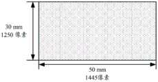
下面以一个具体例子描述根据本发明实施例的近眼显示器的部分参数。如图16所示,近眼显示器的摄像显示面板的尺寸可以为:50mm×30mm,像素(即摄像显示单元)数量为:1445×1250。一个发光单元的的直径为8μm,感光元件的直径为8μm,两个相邻发光单元的中心之间的距离为10μm,两个相邻发光单元之间间隔的距离为5μm,子准直滤镜中的透光孔的直径为2μm,两个相邻子准直透镜之间间隔的距离为2μm,红色发光单元对应的子准直透镜的曲率半径Rr=8μm,绿色发光单元对应的子准直透镜的曲率半径Rg>Rr,蓝色发光单元对应的子准直透镜的曲率半径Rb>Rg,T1=36μm,胶水1的折射率、准直透镜341的基材的折射率、和第一子折射结构321的基材的折射率均为1.7,胶水2的折射率和胶水3的折射率为1.45,近眼显示器的厚度可以为200μm或1mm。近眼显示器的厚度越厚,刚度越高。应理解,这个例子是为了帮助本领域技术人员更好地理解本发明实施例,而非要限制本发明实施例的范围。本领域技术人员根据上述例子,显然可以进行各种等价的修改或变化,这样的修改或变化也落入本发明实施例的范围内。The following describes some parameters of the near-eye display according to the embodiment of the present invention with a specific example. As shown in FIG. 16 , the size of the camera display panel of the near-eye display may be: 50mm×30mm, and the number of pixels (ie, camera display units) is: 1445×1250. The diameter of one light-emitting unit is 8 μm, the diameter of the photosensitive element is 8 μm, the distance between the centers of two adjacent light-emitting units is 10 μm, the distance between the two adjacent light-emitting units is 5 μm, and the sub-collimation filter The diameter of the light-transmitting hole is 2 μm, the distance between two adjacent sub-collimating lenses is 2 μm, the curvature radius of the sub-collimating lens corresponding to the red light-emitting unit is Rr=8 μm, and the sub-collimating lens corresponding to the green light-emitting unit is 2 μm. The curvature radius of the lens is Rg>Rr, the curvature radius of the sub-collimating lens corresponding to the blue light-emitting unit is Rb>Rg, T1 =36 μm, the refractive index of glue 1, the refractive index of the base material of the
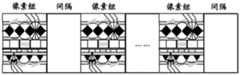
如上文描述,本发明实施例中的摄像显示面板上的多个摄像显示单元可以采用多种排列方式,例如,摄像显示面板上的多个摄像显示单元可以采用如图17或图18所示的排列方式,图17和图18中以一个摄像显示单元包括R、G、B三个子摄像显示单元为例。其中每个子摄像显示单元从上至下包括如图13中所示的一个第二斜槽、该第二斜槽对应的子准直滤镜、该子准直滤镜对应的子感光元件、该子感光元件对应的发光元件、该发光元件对应的子准直透镜和该子准直透镜对应的第一斜槽。类似的,每个摄像显示单元中的多个子摄像显示单元也可以采用多种排列方式布置,本发明实施例对此不作限定。例如,例如每个摄像显示单元中的多个子摄像显示单元可以如图17所示呈一字形排列,还可以如图18所示呈三角形排列。As described above, the plurality of imaging and display units on the imaging display panel in the embodiment of the present invention may adopt various arrangements. For example, the plurality of imaging and display units on the imaging display panel may be as shown in FIG. 17 or FIG. Arrangement, in FIG. 17 and FIG. 18 , one camera display unit includes three sub camera display units R, G, and B as an example. Each of the sub-camera display units includes, from top to bottom, a second inclined slot as shown in FIG. 13 , a sub-collimation filter corresponding to the second inclined slot, a sub-photosensitive element corresponding to the sub-collimation filter, and the sub-collimation filter. The light-emitting element corresponding to the sub-photosensitive element, the sub-collimating lens corresponding to the light-emitting element, and the first inclined groove corresponding to the sub-collimating lens. Similarly, the plurality of sub-camera display units in each camera display unit may also be arranged in various arrangements, which are not limited in this embodiment of the present invention. For example, for example, a plurality of sub-camera display units in each camera display unit may be arranged in a line as shown in FIG. 17 , or may be arranged in a triangle as shown in FIG. 18 .
以图17所示的排列方式为例。假设x方向上排列了1445个摄像显示单元,y方向上排列了1250个摄像显示单元,x方向上相邻的两个摄像显示单元之间的距离为34.59μm,y方向上相邻的两个摄像显示单元之间的距离为24μm,则近眼显示器在x方向上的最小宽度为1444×34.59μm,在y方向上的最小高度为1249×24μm。Take the arrangement shown in Figure 17 as an example. Assuming that 1445 camera display units are arranged in the x direction and 1250 camera display units are arranged in the y direction, the distance between two adjacent camera display units in the x direction is 34.59 μm, and the two adjacent camera display units in the y direction are 34.59 μm. When the distance between the imaging and display units is 24 μm, the minimum width of the near-eye display in the x-direction is 1444×34.59 μm, and the minimum height in the y-direction is 1249×24 μm.
需要说明的是,上述各个实施例中的胶水均可以采用透明胶水,透明胶水的透光率较高,有利于提高近眼显示器的成像质量。上述各个实施例中的折射结构、聚光透镜、准直滤镜基材可以为透明基材。折射结构采用的透明基材、聚光透镜采用的透明基材、准直滤镜采用的透明基材以及相邻的像素组之间填充的透明基材可以为相同的透明基材,也可以为不同的透明基材,本发明实施例对此并不限定。It should be noted that, transparent glue can be used as the glue in each of the above embodiments, and the transparent glue has high light transmittance, which is beneficial to improve the imaging quality of the near-eye display. The refraction structure, condensing lens, and collimating filter substrates in the above embodiments may be transparent substrates. The transparent base material used for the refraction structure, the transparent base material used for the condenser lens, the transparent base material used for the collimating filter, and the transparent base material filled between adjacent pixel groups may be the same transparent base material, or may be the same transparent base material. Different transparent substrates are not limited in this embodiment of the present invention.
图19是根据本发明实施例的近眼显示器中的准直滤镜的实现工艺的示意性流程图。如图19所示,该实现工艺流程如下所示。FIG. 19 is a schematic flowchart of an implementation process of a collimating filter in a near-eye display according to an embodiment of the present invention. As shown in Figure 19, the implementation process flow is as follows.
步骤1、通过纳米印压技术在有机透明材料基材上形成透镜阵列及凹槽。Step 1. Form a lens array and grooves on an organic transparent material substrate by a nano-imprint technology.
步骤2、在透镜阵列及凹槽的表面印刷吸光涂料,形成吸光凹槽。例如,印刷黑色吸光油墨,使得吸光凹槽内充满油墨,具备吸光特性。Step 2, printing light-absorbing paint on the surface of the lens array and the groove to form a light-absorbing groove. For example, printing black light-absorbing ink so that the light-absorbing grooves are filled with ink and have light-absorbing properties.
步骤3、采用高精度激光或蚀刻工艺在相邻吸光凹槽之间的表面开孔。例如,在对应微透镜焦点处使用激光出去吸光油墨,形成光通路。Step 3, using a high-precision laser or etching process to open holes on the surface between adjacent light-absorbing grooves. For example, a laser is used at the focal point of the corresponding microlens to emit light-absorbing ink to form a light path.
步骤4、将两个通过以上步骤得到的透镜组的透光孔相向对正粘贴,即可完成准直透镜的制作。Step 4: align the light-transmitting holes of the two lens groups obtained by the above steps to face each other, and then the production of the collimating lens can be completed.
应理解,图19所示仅为准直滤镜的实现工艺的一种例子,本发明实施例并不限于此。It should be understood that FIG. 19 is only an example of an implementation process of the collimating filter, and the embodiment of the present invention is not limited thereto.
还应理解,通过步骤1至3即可完成准直透镜的制作。It should also be understood that the fabrication of the collimating lens can be completed through steps 1 to 3.
以上所述,仅为本发明实施例的具体实施方式,但本发明实施例的保护范围并不局限于此,任何熟悉本技术领域的技术人员在本发明实施例揭露的技术范围内,可轻易想到变化或替换,都应涵盖在本发明实施例的保护范围之内。因此,本发明实施例的保护范围应所述以权利要求的保护范围为准。The above are only specific implementations of the embodiments of the present invention, but the protection scope of the embodiments of the present invention is not limited thereto. Changes or substitutions that are conceivable should all fall within the protection scope of the embodiments of the present invention. Therefore, the protection scope of the embodiments of the present invention should be based on the protection scope of the claims.
Claims (28)


Priority Applications (1)
| Application Number | Priority Date | Filing Date | Title |
|---|---|---|---|
| CN201710547136.8ACN107329267B (en) | 2017-07-06 | 2017-07-06 | Near-eye display and near-eye display system |
Applications Claiming Priority (1)
| Application Number | Priority Date | Filing Date | Title |
|---|---|---|---|
| CN201710547136.8ACN107329267B (en) | 2017-07-06 | 2017-07-06 | Near-eye display and near-eye display system |
Publications (2)
| Publication Number | Publication Date |
|---|---|
| CN107329267A CN107329267A (en) | 2017-11-07 |
| CN107329267Btrue CN107329267B (en) | 2020-03-10 |
Family
ID=60196357
Family Applications (1)
| Application Number | Title | Priority Date | Filing Date |
|---|---|---|---|
| CN201710547136.8AActiveCN107329267B (en) | 2017-07-06 | 2017-07-06 | Near-eye display and near-eye display system |
Country Status (1)
| Country | Link |
|---|---|
| CN (1) | CN107329267B (en) |
Families Citing this family (2)
| Publication number | Priority date | Publication date | Assignee | Title |
|---|---|---|---|---|
| CN110376742A (en) | 2017-03-23 | 2019-10-25 | 华为机器有限公司 | Near-eye display and near-eye display system |
| CN114185170A (en)* | 2020-09-14 | 2022-03-15 | 中强光电股份有限公司 | Near-eye light field display device |
Family Cites Families (3)
| Publication number | Priority date | Publication date | Assignee | Title |
|---|---|---|---|---|
| JP5119636B2 (en)* | 2006-09-27 | 2013-01-16 | ソニー株式会社 | Display device and display method |
| US8582209B1 (en)* | 2010-11-03 | 2013-11-12 | Google Inc. | Curved near-to-eye display |
| US9798145B2 (en)* | 2014-05-23 | 2017-10-24 | Qualcomm Incorporated | Method and apparatus for see-through near eye display |
- 2017
- 2017-07-06CNCN201710547136.8Apatent/CN107329267B/enactiveActive
Also Published As
| Publication number | Publication date |
|---|---|
| CN107329267A (en) | 2017-11-07 |
Similar Documents
| Publication | Publication Date | Title |
|---|---|---|
| CN107490862B (en) | Near-eye display and near-eye display system | |
| CN103037180B (en) | Imageing sensor and picture pick-up device | |
| CN107300770B (en) | Near-Eye Displays and Near-Eye Display Systems | |
| JP5842146B2 (en) | Solid-state imaging device, imaging device, and spectroscopic element | |
| CN104270555B (en) | A kind of curved surface cmos image sensor camera module | |
| WO2019062480A1 (en) | Near-eye optical imaging system, near-eye display device and head-mounted display device | |
| CN106164748A (en) | Projection arrangement | |
| CN103119516A (en) | Light field imaging device and image processing device | |
| US12219273B2 (en) | Camera module, camera, terminal device, and method for determining image information | |
| CN103091850A (en) | Naked-eye multi-dimensional display assembly and display thereof | |
| JP2008294819A (en) | Image pick-up device | |
| CN111175990A (en) | light field display system | |
| US20140104317A1 (en) | Image displaying device and method | |
| CN107329267B (en) | Near-eye display and near-eye display system | |
| CN111190325A (en) | All-solid-state holographic shooting device | |
| JP6907616B2 (en) | Stereoscopic image imaging / display combined device and head mount device | |
| CN206115049U (en) | Virtual display panel and display device | |
| KR102467346B1 (en) | Display assembly with electronically emulated transparency | |
| US20220343471A1 (en) | Electronic apparatus | |
| TW201524208A (en) | Optical assembly for plenoptic camera | |
| CN110161712A (en) | Display system and head-wearing display device | |
| WO2020181939A1 (en) | Display device and display method therefor | |
| JP7652777B2 (en) | Display device | |
| CN115715379B (en) | Near-eye display device and display method thereof | |
| JP7408537B2 (en) | Near eye light field display device |
Legal Events
| Date | Code | Title | Description |
|---|---|---|---|
| PB01 | Publication | ||
| PB01 | Publication | ||
| SE01 | Entry into force of request for substantive examination | ||
| SE01 | Entry into force of request for substantive examination | ||
| GR01 | Patent grant | ||
| GR01 | Patent grant |