CN107320808B - A medical infusion device - Google Patents
A medical infusion deviceDownload PDFInfo
- Publication number
- CN107320808B CN107320808BCN201710537389.7ACN201710537389ACN107320808BCN 107320808 BCN107320808 BCN 107320808BCN 201710537389 ACN201710537389 ACN 201710537389ACN 107320808 BCN107320808 BCN 107320808B
- Authority
- CN
- China
- Prior art keywords
- rod
- support column
- trash
- threaded
- threaded rod
- Prior art date
- Legal status (The legal status is an assumption and is not a legal conclusion. Google has not performed a legal analysis and makes no representation as to the accuracy of the status listed.)
- Expired - Fee Related
Links
- 238000001802infusionMethods0.000titleclaimsabstractdescription19
- 239000010813municipal solid wasteSubstances0.000claimsabstractdescription33
- 239000004033plasticSubstances0.000claimsdescription3
- 230000008673vomitingEffects0.000abstractdescription5
- 210000004916vomitAnatomy0.000abstractdescription4
- 239000003814drugSubstances0.000abstractdescription2
- 206010047700VomitingDiseases0.000abstract1
- 208000024891symptomDiseases0.000abstract1
- 238000010586diagramMethods0.000description1
- 238000000034methodMethods0.000description1
- 230000000474nursing effectEffects0.000description1
Images

Classifications
- A—HUMAN NECESSITIES
- A61—MEDICAL OR VETERINARY SCIENCE; HYGIENE
- A61M—DEVICES FOR INTRODUCING MEDIA INTO, OR ONTO, THE BODY; DEVICES FOR TRANSDUCING BODY MEDIA OR FOR TAKING MEDIA FROM THE BODY; DEVICES FOR PRODUCING OR ENDING SLEEP OR STUPOR
- A61M5/00—Devices for bringing media into the body in a subcutaneous, intra-vascular or intramuscular way; Accessories therefor, e.g. filling or cleaning devices, arm-rests
- A61M5/14—Infusion devices, e.g. infusing by gravity; Blood infusion; Accessories therefor
- A61M5/1414—Hanging-up devices
- A61M5/1415—Stands, brackets or the like for supporting infusion accessories
Landscapes
- Health & Medical Sciences (AREA)
- Vascular Medicine (AREA)
- Engineering & Computer Science (AREA)
- Anesthesiology (AREA)
- Biomedical Technology (AREA)
- Heart & Thoracic Surgery (AREA)
- Hematology (AREA)
- Life Sciences & Earth Sciences (AREA)
- Animal Behavior & Ethology (AREA)
- General Health & Medical Sciences (AREA)
- Public Health (AREA)
- Veterinary Medicine (AREA)
- Refuse Receptacles (AREA)
- Accommodation For Nursing Or Treatment Tables (AREA)
Abstract
Translated fromChinese
Description
Translated fromChinese技术领域technical field
本发明涉及内科护理技术领域,尤其涉及一种内科输液装置。The invention relates to the technical field of medical nursing, in particular to a medical infusion device.
背景技术Background technique
随着社会的发展与进步,人们的生活部水平也在逐步的提高,相对的医疗设施也在提高完善,对于内科的输液装置只是一个简单的支架,且高度不可调,内科病人会经常的呕吐,现有的垃圾桶都没有桶盖,而有桶盖时需要手动打开桶盖才能使用,而内科病人在输液时不方便使用手去打开桶盖,不便于使用。With the development and progress of society, people's living standards are gradually improving, and the relative medical facilities are also improving and perfecting. For the infusion device of internal medicine, it is just a simple stent, and the height is not adjustable, and medical patients will often vomit , the existing trash cans do not have a bucket cover, and when there is a bucket cover, you need to manually open the bucket cover to use, and it is inconvenient for medical patients to use their hands to open the bucket cover during infusion, which is inconvenient to use.
发明内容SUMMARY OF THE INVENTION
本发明的目的是为了解决现有技术中存在的缺点,而提出的一种内科输液装置。The purpose of the present invention is to propose a medical infusion device in order to solve the shortcomings existing in the prior art.
为了实现上述目的,本发明采用了如下技术方案:In order to achieve the above object, the present invention adopts the following technical solutions:
一种内科输液装置,包括底座,所述底座上设有支撑柱,所述支撑柱内设有腔室,所述腔室的左右两端内壁上均设有第一滑槽,两个所述第一滑槽内均设有第一凸形滑块,所述腔室内设有升降板,所述升降板的两端侧壁分别与两个第一凸形滑块的侧壁连接,所述升降板上设有上下连通的第一螺纹孔,且第一螺纹孔内螺纹连接有第一螺纹杆,所述第一螺纹杆的上端穿过腔室的顶面并延伸至支撑柱外,且第一螺纹杆与支撑柱转动连接,所述第一螺纹杆的上端连接有第一手柄,所述支撑柱的上端设有开口,且开口内贯穿设有升降杆,所述升降杆的下端与升降板的上端连接,所述升降杆的侧壁上设有挂钩,且挂钩靠近升降杆的上端设置,所述支撑柱的侧壁上竖直设有第二滑槽,所述第二滑槽内设有第二凸形滑块,所述第二凸形滑块上设有上下连通的第二螺纹孔,且第二螺纹孔内螺纹连接有第二螺纹杆,所述第二螺纹杆穿过第二凹槽的顶面并延伸至支撑柱外,且第二螺纹杆与支撑柱转动连接,所述第二螺纹杆的上端设有第二手柄,所述第二凸形滑块的侧壁连接有垃圾桶,所述垃圾桶远离支撑柱的一端侧壁上转动连接有桶盖,所述桶盖上转动连接有第一连接杆,所述第一连接杆远离桶盖的一端转动连接有第二连接杆,所述垃圾桶远离支撑柱的一端侧壁上转动连接有转动杆,所述转动杆的上端与第二连接杆的下端连接,所述垃圾桶的侧壁与弹簧的上端连接,所述弹簧的下端与转动杆的上端连接,所述垃圾桶的侧壁上设有第三滑槽,且第三滑槽位于转动杆的下方,所述第三滑槽内设有第三凸形滑块,所述第三凸形滑块的侧壁连接有伸缩杆,所述伸缩杆远离垃圾桶的一端连接有移动杆,所述移动杆的上端与转动杆的下端转动连接,所述移动杆的下端连接有脚踏板。A medical infusion device, comprising a base, a support column is arranged on the base, a chamber is arranged in the support column, the inner walls of the left and right ends of the chamber are provided with first chute, two of the A first convex sliding block is arranged in the first chute, a lifting plate is arranged in the cavity, and the side walls at both ends of the lifting plate are respectively connected with the side walls of the two first convex sliding blocks. The lifting plate is provided with a first threaded hole that communicates up and down, and a first threaded rod is threadedly connected in the first threaded hole, and the upper end of the first threaded rod passes through the top surface of the chamber and extends to the outside of the support column, and The first threaded rod is rotatably connected with the support column, the upper end of the first threaded rod is connected with a first handle, the upper end of the support column is provided with an opening, and a lifting rod is arranged through the opening, and the lower end of the lifting rod is connected with the lifting rod. The upper end of the lift plate is connected, the side wall of the lift rod is provided with a hook, and the hook is arranged near the upper end of the lift rod, the side wall of the support column is vertically provided with a second chute, the second chute There is a second convex sliding block inside, the second convex sliding block is provided with a second threaded hole that communicates up and down, and the second threaded hole is threadedly connected with a second threaded rod, and the second threaded rod passes through the second threaded hole. The upper end of the second threaded rod is provided with a second handle, and the side of the second convex slider is A trash can is connected to the wall, a bucket cover is rotatably connected to the side wall of one end of the trash can away from the support column, a first connecting rod is rotatably connected to the bucket cover, and an end of the first connecting rod away from the bucket cover is rotatably connected There is a second connecting rod, the side wall of one end of the trash can away from the support column is rotatably connected with a rotating rod, the upper end of the rotating rod is connected with the lower end of the second connecting rod, and the side wall of the trash can is connected with the upper end of the spring. The lower end of the spring is connected with the upper end of the rotating rod, the side wall of the trash can is provided with a third chute, and the third chute is located below the rotating rod, and the third chute is provided with a third chute. Three convex sliding blocks, the side wall of the third convex sliding block is connected with a telescopic rod, the end of the telescopic rod away from the trash can is connected with a moving rod, and the upper end of the moving rod is rotatably connected with the lower end of the rotating rod, A foot pedal is connected to the lower end of the moving rod.
优选地,所述底座的下端设有滚轮。Preferably, the lower end of the base is provided with a roller.
优选地,所述第一螺杆和第二螺纹杆的下端均设有凸块。Preferably, protrusions are provided on the lower ends of the first screw rod and the second threaded rod.
优选地,所述垃圾桶内设有塑料袋。Preferably, a plastic bag is provided in the trash can.
优选地,所述桶盖的下端设有一层橡胶层。Preferably, a rubber layer is provided at the lower end of the bucket cover.
本发明中,摇动第一手柄通过第一螺纹杆带动升降板的移动,则带动升降杆上的挂钩移动,根据输液瓶需要的高度通过摇动第一手柄来调整,摇动第二手柄通过第二螺纹杆带动第二凸形滑块的移动,则带动垃圾桶的移动,可通过摇动第二手柄将垃圾桶调整到合适的高度,当用脚将脚踏板向下踩时,通过第一连接杆带动使得桶盖打开,可根据需要调整输液瓶和垃圾桶的高度,当病人呕吐时用脚就能打开垃圾桶的桶盖,操作简单,设计人性化。In the present invention, shaking the first handle drives the movement of the lifting plate through the first threaded rod, then drives the hook on the lifting rod to move, according to the required height of the infusion bottle to adjust by shaking the first handle, shaking the second handle through the second thread The rod drives the movement of the second convex slider, and then drives the movement of the trash can. The trash can can be adjusted to a suitable height by shaking the second handle. When the foot pedal is stepped down, the first connecting rod Drive the bucket lid to open, and the height of the infusion bottle and the trash can can be adjusted as needed. When the patient vomits, the bucket lid of the trash can can be opened with their feet. The operation is simple and the design is user-friendly.
附图说明Description of drawings
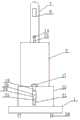
图1为本发明提出的一种内科输液装置的结构示意图;1 is a schematic structural diagram of a medical infusion device proposed by the present invention;
图2为图1的右视图。FIG. 2 is a right side view of FIG. 1 .
图中:1底座、2支撑柱、3腔室、4第一滑槽、5第一凸形滑块、6升降板、7升降杆、8挂钩、9第一螺纹杆、10第一手柄、11第二滑槽、12第二凸形滑块、13第二螺纹杆、14第二手柄、15垃圾桶、16桶盖、17第一连接杆、18第二连接杆、19转动杆、20弹簧、21第三滑槽、22第三凸形滑块、23伸缩杆、24移动杆、25脚踏板、26滚轮。In the figure: 1 base, 2 support column, 3 chamber, 4 first chute, 5 first convex slider, 6 lifting plate, 7 lifting rod, 8 hook, 9 first threaded rod, 10 first handle, 11 second chute, 12 second convex slider, 13 second threaded rod, 14 second handle, 15 trash can, 16 bucket lid, 17 first connecting rod, 18 second connecting rod, 19 rotating rod, 20 Spring, 21 third chute, 22 third convex slider, 23 telescopic rod, 24 moving rod, 25 foot pedal, 26 roller.
具体实施方式Detailed ways
下面将结合本发明实施例中的附图,对本发明实施例中的技术方案进行清楚、完整地描述,显然,所描述的实施例仅仅是本发明一部分实施例,而不是全部的实施例。The technical solutions in the embodiments of the present invention will be clearly and completely described below with reference to the accompanying drawings in the embodiments of the present invention. Obviously, the described embodiments are only a part of the embodiments of the present invention, but not all of the embodiments.
参照图1-2,一种内科输液装置,包括底座1,底座1上设有支撑柱2,支撑柱2内设有腔室3,腔室3的左右两端内壁上均设有第一滑槽4,两个第一滑槽4内均设有第一凸形滑块5,腔室3内设有升降板6,升降板6的两端侧壁分别与两个第一凸形滑块5的侧壁连接,升降板6上设有上下连通的第一螺纹孔,且第一螺纹孔内螺纹连接有第一螺纹杆9,第一螺纹杆9的上端穿过腔室3的顶面并延伸至支撑柱2外,且第一螺纹杆9与支撑柱2转动连接,第一螺纹杆9的上端连接有第一手柄10,支撑柱2的上端设有开口,且开口内贯穿设有升降杆7,升降杆7的下端与升降板6的上端连接,升降杆7的侧壁上设有挂钩8,且挂钩8靠近升降杆7的上端设置,支撑柱2的侧壁上竖直设有第二滑槽11,第二滑槽11内设有第二凸形滑块12,第二凸形滑块12上设有上下连通的第二螺纹孔,且第二螺纹孔内螺纹连接有第二螺纹杆13,第一螺杆9和第二螺纹杆13的下端均设有凸块,分别对第一螺纹杆9和第二螺纹杆13进行限位,第二螺纹杆13穿过第二凹槽11的顶面并延伸至支撑柱2外,且第二螺纹杆13与支撑柱2转动连接,第二螺纹杆13的上端设有第二手柄14,第二凸形滑块12的侧壁连接有垃圾桶15,垃圾桶15内设有塑料袋,便于清除垃圾桶15内的垃圾,垃圾桶15远离支撑柱2的一端侧壁上转动连接有桶盖16,桶盖16的下端设有一层橡胶层,使得桶盖16与垃圾桶15紧密接触,避免呕吐物的异味挥发出来,桶盖16上转动连接有第一连接杆17,第一连接杆17远离桶盖16的一端转动连接有第二连接杆18,垃圾桶15远离支撑柱2的一端侧壁上转动连接有转动杆19,转动杆19的上端与第二连接杆18的下端连接,垃圾桶15的侧壁与弹簧20的上端连接,弹簧20的下端与转动杆19的上端连接,垃圾桶15的侧壁上设有第三滑槽21,且第三滑槽21位于转动杆19的下方,第三滑槽21内设有第三凸形滑块22,第三凸形滑块22的侧壁连接有伸缩杆23,伸缩杆23远离垃圾桶15的一端连接有移动杆24,移动杆24的上端与转动杆19的下端转动连接,移动杆24的下端连接有脚踏板25,底座1的下端设有滚轮26,便于输液装置的移动。1-2, a medical infusion device includes a
本发明中,摇动第一手柄10通过第一螺纹杆9带动升降板6的移动,则带动升降杆7上的挂钩8移动,挂钩8上挂有输液瓶,根据输液瓶需要的高度通过摇动第一手柄10来调整,摇动第二手柄14通过第二螺纹杆13带动第二凸形滑块12的移动,则带动垃圾桶15的移动,可通过摇动第二手柄14将垃圾桶15调整到合适的高度,当用脚将脚踏板25向下踩时,使得移动杆24向下移动,通过第一连接杆17带动使得桶盖16打开,操作简单,设计人性化。In the present invention, shaking the
以上所述,仅为本发明较佳的具体实施方式,但本发明的保护范围并不局限于此,任何熟悉本技术领域的技术人员在本发明揭露的技术范围内,根据本发明的技术方案及其发明构思加以等同替换或改变,都应涵盖在本发明的保护范围之内。The above description is only a preferred embodiment of the present invention, but the protection scope of the present invention is not limited to this. The equivalent replacement or change of the inventive concept thereof shall be included within the protection scope of the present invention.
Claims (4)
Translated fromChinesePriority Applications (1)
| Application Number | Priority Date | Filing Date | Title |
|---|---|---|---|
| CN201710537389.7ACN107320808B (en) | 2017-07-04 | 2017-07-04 | A medical infusion device |
Applications Claiming Priority (1)
| Application Number | Priority Date | Filing Date | Title |
|---|---|---|---|
| CN201710537389.7ACN107320808B (en) | 2017-07-04 | 2017-07-04 | A medical infusion device |
Publications (2)
| Publication Number | Publication Date |
|---|---|
| CN107320808A CN107320808A (en) | 2017-11-07 |
| CN107320808Btrue CN107320808B (en) | 2020-10-27 |
Family
ID=60197900
Family Applications (1)
| Application Number | Title | Priority Date | Filing Date |
|---|---|---|---|
| CN201710537389.7AExpired - Fee RelatedCN107320808B (en) | 2017-07-04 | 2017-07-04 | A medical infusion device |
Country Status (1)
| Country | Link |
|---|---|
| CN (1) | CN107320808B (en) |
Families Citing this family (2)
| Publication number | Priority date | Publication date | Assignee | Title |
|---|---|---|---|---|
| CN107726114A (en)* | 2017-11-23 | 2018-02-23 | 中山驰马灯饰照明设计工程有限公司 | A kind of portable adjustable street lamp |
| CN107820832A (en)* | 2017-12-08 | 2018-03-23 | 韩雪飞 | A kind of electromechanical integration weeder of adjustable weeding height |
Family Cites Families (10)
| Publication number | Priority date | Publication date | Assignee | Title |
|---|---|---|---|---|
| FR2712266B1 (en)* | 1993-11-08 | 1996-01-19 | Sahfff Sa | Trash can with foot-operated opening. |
| US8597228B2 (en)* | 2009-03-09 | 2013-12-03 | Thermedx, Llc | Fluid deficit monitoring in a fluid management system |
| CN201825362U (en)* | 2010-10-25 | 2011-05-11 | 浙江大学 | Garbage can with pedal-controlled sliding covers |
| CN202724343U (en)* | 2012-07-19 | 2013-02-13 | 西南交通大学 | Transfusion device capable of automatically withdrawing needle and replacing bottle |
| CN202682457U (en)* | 2012-08-02 | 2013-01-23 | 吴小蕾 | Transfusion rack |
| CN103341224A (en)* | 2013-06-22 | 2013-10-09 | 程春梅 | Nursing infusion support |
| CN205145233U (en)* | 2015-07-13 | 2016-04-13 | 张天意 | Internal medicine enema device convenient to transport |
| CN205586303U (en)* | 2016-03-31 | 2016-09-21 | 中国人民解放军第三〇九医院 | Infusion support with fixed box of hanging |
| CN206414555U (en)* | 2016-07-28 | 2017-08-18 | 中国人民解放军总医院 | A kind of lifting infusion stand |
| CN206288532U (en)* | 2016-12-22 | 2017-06-30 | 吕芙蓉 | Novel digestive medical garbage containing barrel |
- 2017
- 2017-07-04CNCN201710537389.7Apatent/CN107320808B/ennot_activeExpired - Fee Related
Also Published As
| Publication number | Publication date |
|---|---|
| CN107320808A (en) | 2017-11-07 |
Similar Documents
| Publication | Publication Date | Title |
|---|---|---|
| CN107320808B (en) | A medical infusion device | |
| CN107669431A (en) | It is a kind of medical patient caring bed | |
| CN206095715U (en) | Movable 24 hour urine collecting device | |
| CN205598126U (en) | Be convenient for lie by internal medicine nursing bed | |
| CN210259786U (en) | Waste collection device is used in operating room nursing | |
| CN203935454U (en) | A kind of urine collecting | |
| CN204072588U (en) | Medical sickbed bracket | |
| CN109925155B (en) | Nursing device capable of carrying out auxiliary treatment on tumor | |
| CN208943074U (en) | A kind of infusion support for orthopaedics infusion | |
| CN209270123U (en) | A medical bed with an intelligent trash can | |
| CN209713514U (en) | A kind of combined type hospital foundation care device | |
| CN218889949U (en) | A vomit collection device for nursing care in tumor departments | |
| CN217014765U (en) | A kind of stent for medical care | |
| CN221672818U (en) | Adjustable drainage bottle fixing device | |
| CN221534580U (en) | Multifunctional wound dressing rack | |
| CN217566786U (en) | Clinical diagnosis and treatment frame combining traditional Chinese medicine and western medicine | |
| CN221490534U (en) | A height-adjustable hand-washing disinfection vehicle | |
| CN208756411U (en) | A liftable and adjustable medical care car | |
| CN216257980U (en) | Urinal placing support | |
| CN216365642U (en) | A new type of card rack type urinal storage rack | |
| CN211568961U (en) | Garbage collection device for operating room nursing | |
| CN204106751U (en) | A kind of medical sharps box support | |
| CN104225729B (en) | A kind of medical sharps box support | |
| CN215853119U (en) | A mobile garbage collection device for an infusion room | |
| CN210417861U (en) | Garbage compaction device and garbage can based on same |
Legal Events
| Date | Code | Title | Description |
|---|---|---|---|
| PB01 | Publication | ||
| PB01 | Publication | ||
| SE01 | Entry into force of request for substantive examination | ||
| SE01 | Entry into force of request for substantive examination | ||
| CB03 | Change of inventor or designer information | Inventor after:Wang Xiaojuan Inventor after:Liu Bing Inventor after:Wang Qing Inventor after:Han Zhulong Inventor after:Tian Fenggang Inventor before:Han Zhulong Inventor before:Tian Fenggang | |
| CB03 | Change of inventor or designer information | ||
| TA01 | Transfer of patent application right | Effective date of registration:20200922 Address after:266000 Jiangsu Road, Shandong, China, No. 16, No. Applicant after:THE AFFILIATED HOSPITAL OF QINGDAO University Address before:A group of urban and rural areas in Xianyang city of Shaanxi Province, South Village 713300 Qianxian County week Applicant before:Han Zhulong | |
| TA01 | Transfer of patent application right | ||
| GR01 | Patent grant | ||
| GR01 | Patent grant | ||
| CF01 | Termination of patent right due to non-payment of annual fee | Granted publication date:20201027 Termination date:20210704 | |
| CF01 | Termination of patent right due to non-payment of annual fee |