CN107315280B - Backlight module and its manufacturing method, display device - Google Patents
Backlight module and its manufacturing method, display deviceDownload PDFInfo
- Publication number
- CN107315280B CN107315280BCN201710628510.7ACN201710628510ACN107315280BCN 107315280 BCN107315280 BCN 107315280BCN 201710628510 ACN201710628510 ACN 201710628510ACN 107315280 BCN107315280 BCN 107315280B
- Authority
- CN
- China
- Prior art keywords
- light
- light guide
- volume grating
- grating
- layer
- Prior art date
- Legal status (The legal status is an assumption and is not a legal conclusion. Google has not performed a legal analysis and makes no representation as to the accuracy of the status listed.)
- Active
Links
Images


Classifications
- G—PHYSICS
- G02—OPTICS
- G02B—OPTICAL ELEMENTS, SYSTEMS OR APPARATUS
- G02B6/00—Light guides; Structural details of arrangements comprising light guides and other optical elements, e.g. couplings
- G02B6/0001—Light guides; Structural details of arrangements comprising light guides and other optical elements, e.g. couplings specially adapted for lighting devices or systems
- G02B6/0011—Light guides; Structural details of arrangements comprising light guides and other optical elements, e.g. couplings specially adapted for lighting devices or systems the light guides being planar or of plate-like form
- G02B6/0033—Means for improving the coupling-out of light from the light guide
- G02B6/0035—Means for improving the coupling-out of light from the light guide provided on the surface of the light guide or in the bulk of it
- G02B6/0038—Linear indentations or grooves, e.g. arc-shaped grooves or meandering grooves, extending over the full length or width of the light guide
- G—PHYSICS
- G02—OPTICS
- G02B—OPTICAL ELEMENTS, SYSTEMS OR APPARATUS
- G02B6/00—Light guides; Structural details of arrangements comprising light guides and other optical elements, e.g. couplings
- G02B6/0001—Light guides; Structural details of arrangements comprising light guides and other optical elements, e.g. couplings specially adapted for lighting devices or systems
- G02B6/0011—Light guides; Structural details of arrangements comprising light guides and other optical elements, e.g. couplings specially adapted for lighting devices or systems the light guides being planar or of plate-like form
- G02B6/0013—Means for improving the coupling-in of light from the light source into the light guide
- G02B6/0015—Means for improving the coupling-in of light from the light source into the light guide provided on the surface of the light guide or in the bulk of it
- G—PHYSICS
- G02—OPTICS
- G02F—OPTICAL DEVICES OR ARRANGEMENTS FOR THE CONTROL OF LIGHT BY MODIFICATION OF THE OPTICAL PROPERTIES OF THE MEDIA OF THE ELEMENTS INVOLVED THEREIN; NON-LINEAR OPTICS; FREQUENCY-CHANGING OF LIGHT; OPTICAL LOGIC ELEMENTS; OPTICAL ANALOGUE/DIGITAL CONVERTERS
- G02F1/00—Devices or arrangements for the control of the intensity, colour, phase, polarisation or direction of light arriving from an independent light source, e.g. switching, gating or modulating; Non-linear optics
- G02F1/01—Devices or arrangements for the control of the intensity, colour, phase, polarisation or direction of light arriving from an independent light source, e.g. switching, gating or modulating; Non-linear optics for the control of the intensity, phase, polarisation or colour
- G02F1/13—Devices or arrangements for the control of the intensity, colour, phase, polarisation or direction of light arriving from an independent light source, e.g. switching, gating or modulating; Non-linear optics for the control of the intensity, phase, polarisation or colour based on liquid crystals, e.g. single liquid crystal display cells
- G02F1/133—Constructional arrangements; Operation of liquid crystal cells; Circuit arrangements
- G02F1/1333—Constructional arrangements; Manufacturing methods
- G02F1/1335—Structural association of cells with optical devices, e.g. polarisers or reflectors
- G02F1/1336—Illuminating devices
- G02F1/133602—Direct backlight
- G02F1/133606—Direct backlight including a specially adapted diffusing, scattering or light controlling members
- G—PHYSICS
- G02—OPTICS
- G02B—OPTICAL ELEMENTS, SYSTEMS OR APPARATUS
- G02B6/00—Light guides; Structural details of arrangements comprising light guides and other optical elements, e.g. couplings
- G02B6/0001—Light guides; Structural details of arrangements comprising light guides and other optical elements, e.g. couplings specially adapted for lighting devices or systems
- G02B6/0011—Light guides; Structural details of arrangements comprising light guides and other optical elements, e.g. couplings specially adapted for lighting devices or systems the light guides being planar or of plate-like form
- G02B6/0013—Means for improving the coupling-in of light from the light source into the light guide
- G02B6/0023—Means for improving the coupling-in of light from the light source into the light guide provided by one optical element, or plurality thereof, placed between the light guide and the light source, or around the light source
- G02B6/0026—Wavelength selective element, sheet or layer, e.g. filter or grating
- G—PHYSICS
- G02—OPTICS
- G02B—OPTICAL ELEMENTS, SYSTEMS OR APPARATUS
- G02B6/00—Light guides; Structural details of arrangements comprising light guides and other optical elements, e.g. couplings
- G02B6/0001—Light guides; Structural details of arrangements comprising light guides and other optical elements, e.g. couplings specially adapted for lighting devices or systems
- G02B6/0011—Light guides; Structural details of arrangements comprising light guides and other optical elements, e.g. couplings specially adapted for lighting devices or systems the light guides being planar or of plate-like form
- G02B6/0013—Means for improving the coupling-in of light from the light source into the light guide
- G02B6/0023—Means for improving the coupling-in of light from the light source into the light guide provided by one optical element, or plurality thereof, placed between the light guide and the light source, or around the light source
- G02B6/0031—Reflecting element, sheet or layer
- G—PHYSICS
- G02—OPTICS
- G02B—OPTICAL ELEMENTS, SYSTEMS OR APPARATUS
- G02B6/00—Light guides; Structural details of arrangements comprising light guides and other optical elements, e.g. couplings
- G02B6/0001—Light guides; Structural details of arrangements comprising light guides and other optical elements, e.g. couplings specially adapted for lighting devices or systems
- G02B6/0011—Light guides; Structural details of arrangements comprising light guides and other optical elements, e.g. couplings specially adapted for lighting devices or systems the light guides being planar or of plate-like form
- G02B6/0033—Means for improving the coupling-out of light from the light guide
- G02B6/0035—Means for improving the coupling-out of light from the light guide provided on the surface of the light guide or in the bulk of it
- G02B6/004—Scattering dots or dot-like elements, e.g. microbeads, scattering particles, nanoparticles
- G02B6/0043—Scattering dots or dot-like elements, e.g. microbeads, scattering particles, nanoparticles provided on the surface of the light guide
- G—PHYSICS
- G02—OPTICS
- G02B—OPTICAL ELEMENTS, SYSTEMS OR APPARATUS
- G02B6/00—Light guides; Structural details of arrangements comprising light guides and other optical elements, e.g. couplings
- G02B6/0001—Light guides; Structural details of arrangements comprising light guides and other optical elements, e.g. couplings specially adapted for lighting devices or systems
- G02B6/0011—Light guides; Structural details of arrangements comprising light guides and other optical elements, e.g. couplings specially adapted for lighting devices or systems the light guides being planar or of plate-like form
- G02B6/0075—Arrangements of multiple light guides
- G02B6/0076—Stacked arrangements of multiple light guides of the same or different cross-sectional area
Landscapes
- Physics & Mathematics (AREA)
- General Physics & Mathematics (AREA)
- Optics & Photonics (AREA)
- Nonlinear Science (AREA)
- Mathematical Physics (AREA)
- Chemical & Material Sciences (AREA)
- Crystallography & Structural Chemistry (AREA)
- Planar Illumination Modules (AREA)
Abstract
Translated fromChinese
Description
Translated fromChinese技术领域technical field
本公开至少一实施例涉及一种背光模组及其制作方法、显示装置。At least one embodiment of the present disclosure relates to a backlight module, a manufacturing method thereof, and a display device.
背景技术Background technique
在目前的直下式发光二极管(Light Emitting Diode,LED)的背光处理 中,局部动态背光(Local diming)技术可以很大程度的减少功耗,提高成 像对比度,增加灰阶数以及减少残影等,所以对于大尺寸液晶显示面板,使 用直下式的背光模组成为一种趋势。In the current light-emitting diode (Light Emitting Diode, LED) backlight processing, the local dynamic backlight (Local diming) technology can greatly reduce power consumption, improve imaging contrast, increase the number of gray levels and reduce afterimages, etc. Therefore, for large-size LCD panels, the use of direct-type backlight modules has become a trend.
发明内容SUMMARY OF THE INVENTION
本公开的至少一实施例提供一种背光模组及其制作方法、显示装置。该 背光模组中的体光栅结构可以将光源发出的入射光束导入导光部和导光板 中,导入导光部和导光板的光束在导光结构中进行全反射传播,并由取光结 构均匀取出,一方面该背光模组可以使光能得到充分利用,另一方面,该背 光模组中的光源不需要混光高度,从而有效降低了背光模组的厚度。At least one embodiment of the present disclosure provides a backlight module, a manufacturing method thereof, and a display device. The volume grating structure in the backlight module can guide the incident light beam emitted by the light source into the light guide part and the light guide plate, and the light beam introduced into the light guide part and the light guide plate is totally reflected and propagated in the light guide structure, and is uniformly distributed by the light extraction structure. When taken out, on the one hand, the backlight module can make full use of light energy; on the other hand, the light source in the backlight module does not need a light mixing height, thereby effectively reducing the thickness of the backlight module.
本公开的至少一实施例提供一种背光模组,包括:导光结构,包括导光 板以及体光栅层,体光栅层包括呈阵列排布的多个体光栅部以及位于相邻的 体光栅部之间的导光部,体光栅部被配置为将特定波长的光束导入导光部和 导光板;光源层,设置在导光板的主板面上,并且导光板设置在光源层的出 光侧,体光栅层设置在导光板远离光源层的一侧,其中,光源层包括呈阵列 排布的多个光源,光源在体光栅层的正投影落入体光栅部内;以及取光结构, 设置在导光结构远离光源层的一侧,其中,导光结构的折射率大于光源层以 及取光结构的折射率,且导入导光部和导光板的光束在导光板所在平面的入 射角度不小于导光结构的全反射临界角。At least one embodiment of the present disclosure provides a backlight module, including: a light guide structure, including a light guide plate and a volume grating layer, the volume grating layer including a plurality of volume grating parts arranged in an array and located between adjacent volume grating parts The volume grating part is configured to guide the light beam of a specific wavelength into the light guide part and the light guide plate; the light source layer is arranged on the main surface of the light guide plate, and the light guide plate is arranged on the light exit side of the light source layer, and the volume grating The layer is arranged on the side of the light guide plate away from the light source layer, wherein the light source layer includes a plurality of light sources arranged in an array, and the orthographic projection of the light sources on the volume grating layer falls into the volume grating part; and the light extraction structure is arranged on the light guide structure The side away from the light source layer, wherein the refractive index of the light guide structure is greater than the refractive index of the light source layer and the light extraction structure, and the incident angle of the light beam introduced into the light guide part and the light guide plate on the plane where the light guide plate is located is not less than that of the light guide structure. The critical angle of total reflection.
例如,在本公开一实施例提供的背光模组中,体光栅层的导光部的折射 率与导光板的折射率相等。For example, in the backlight module provided by an embodiment of the present disclosure, the refractive index of the light guide portion of the volume grating layer is equal to the refractive index of the light guide plate.
例如,在本公开一实施例提供的背光模组中,体光栅部包括光栅条纹面, 光栅条纹面位于体光栅层中的入射光束的入射方向与出射光束的出射方向 之间的夹角的角平分线上。For example, in the backlight module provided by an embodiment of the present disclosure, the volume grating portion includes a grating fringe surface, and the grating fringe surface is located in the volume grating layer at an angle between the incident direction of the incident light beam and the outgoing direction of the outgoing light beam. bisector.
例如,在本公开一实施例提供的背光模组中,体光栅层为层叠结构,包 括:For example, in the backlight module provided by an embodiment of the present disclosure, the volume grating layer is a laminated structure, including:
第一体光栅层,包括第一体光栅部,被配置为仅将入射光束中的第一颜 色的光导入导光板和导光部,其中,第一体光栅部包括第一光栅条纹面;The first volume grating layer, comprising a first volume grating portion, is configured to guide only the light of the first color in the incident light beam into the light guide plate and the light guide portion, wherein the first volume grating portion comprises a first grating fringe surface;
第二体光栅层,包括第二体光栅部,被配置为仅将入射光束中的第二颜 色的光导入导光板和导光部,其中,第二体光栅部包括第二光栅条纹面;The second volume grating layer, comprising a second volume grating portion, is configured to guide only the light of the second color in the incident light beam into the light guide plate and the light guide portion, wherein the second volume grating portion includes a second grating fringe surface;
第三体光栅层,包括第三体光栅部,被配置为仅将入射光束中的第三颜 色的光导入导光板和导光部,其中,第三体光栅部包括第三光栅条纹面。The third volume grating layer, including the third volume grating part, is configured to guide only the light of the third color in the incident light beam into the light guide plate and the light guide part, wherein the third volume grating part includes the third grating fringe surface.
例如,在本公开一实施例提供的背光模组中,第一体光栅层、第二体光 栅层和第三体光栅层的厚度分别为5-20μm。For example, in the backlight module provided by an embodiment of the present disclosure, the thicknesses of the first volume grating layer, the second volume grating layer, and the third volume grating layer are respectively 5-20 μm.
例如,在本公开一实施例提供的背光模组中,第一体光栅部的光栅条纹 周期、第二体光栅部的光栅条纹周期、第三体光栅部的光栅条纹周期不全相 同,和/或,第一光栅条纹面、第二光栅条纹面、第三光栅条纹面各自与入射 光束的夹角不全相同。For example, in the backlight module provided by an embodiment of the present disclosure, the grating fringe period of the first volume grating portion, the grating fringe period of the second volume grating portion, and the grating fringe period of the third volume grating portion are not all the same, and/or , the included angles of the first grating fringe surface, the second grating fringe surface, and the third grating fringe surface and the incident light beam are not all the same.
例如,在本公开一实施例提供的背光模组中,导光板的厚度不大于1 mm。For example, in the backlight module provided by an embodiment of the present disclosure, the thickness of the light guide plate is not greater than 1 mm.
例如,在本公开一实施例提供的背光模组中,光源为准直光源。For example, in the backlight module provided by an embodiment of the present disclosure, the light source is a collimated light source.
例如,在本公开一实施例提供的背光模组中,取光结构包括:For example, in the backlight module provided by an embodiment of the present disclosure, the light extraction structure includes:
网点膜,设置在体光栅层远离光源层一侧的表面。The dot film is arranged on the surface of the volume grating layer on the side away from the light source layer.
例如,在本公开一实施例提供的背光模组中,还包括:For example, in the backlight module provided by an embodiment of the present disclosure, it further includes:
反射层,设置在光源层远离导光结构的一侧。The reflection layer is arranged on the side of the light source layer away from the light guide structure.
例如,在本公开一实施例提供的背光模组中,还包括:For example, in the backlight module provided by an embodiment of the present disclosure, it further includes:
驱动电路,与多个光源相连,被配置为调节多个光源中的每个光源的发 光强度。A drive circuit, connected to the plurality of light sources, is configured to adjust the luminous intensity of each of the plurality of light sources.
本公开的至少一实施例提供一种背光模组的制作方法,包括:形成导光 结构,包括形成导光板以及体光栅层,体光栅层包括呈阵列排布的多个体光 栅部以及位于相邻的体光栅部之间的导光部,体光栅部被配置为将特定波长 的光束导入导光部和导光板;At least one embodiment of the present disclosure provides a method for fabricating a backlight module, including: forming a light guide structure, including forming a light guide plate and a volume grating layer, the volume grating layer including a plurality of volume grating parts arranged in an array and adjacent to each other. the light guide part between the volume grating parts, the volume grating part is configured to guide the light beam of a specific wavelength into the light guide part and the light guide plate;
在导光板的主板面上设置光源层,导光板位于光源层的出光侧,体光栅 层形成在导光板远离光源层的一侧,其中,光源层包括呈阵列排布的多个光 源,光源在体光栅层的正投影落入体光栅部内;以及A light source layer is arranged on the main surface of the light guide plate, the light guide plate is located on the light emitting side of the light source layer, and the volume grating layer is formed on the side of the light guide plate away from the light source layer, wherein the light source layer includes a plurality of light sources arranged in an array, and the light sources are located on the side of the light guide plate away from the light source layer. the orthographic projection of the volume grating layer falls within the volume grating portion; and
在导光结构远离光源层的一侧形成取光结构,A light extraction structure is formed on the side of the light guide structure away from the light source layer,
其中,导光结构的折射率大于光源层以及取光结构的折射率,且导入导 光部和导光板的光束在导光板所在平面的入射角度不小于导光结构的全反 射临界角。Wherein, the refractive index of the light guide structure is greater than the refractive index of the light source layer and the light extraction structure, and the incident angle of the light beam introduced into the light guide part and the light guide plate on the plane where the light guide plate is located is not less than the total reflection critical angle of the light guide structure.
例如,在本公开一实施例提供的背光模组的制作方法中,形成体光栅部 包括:For example, in the manufacturing method of the backlight module provided by an embodiment of the present disclosure, forming the volume grating portion includes:
由两束平面光波分别在光折变材料的两侧进行照射曝光,两束平面光波 在光折变材料内发生干涉并形成干涉条纹以形成体光栅部,形成体光栅部后 的光折变材料为体光栅层。Two plane light waves are respectively irradiated and exposed on both sides of the photorefractive material, and the two plane light waves interfere in the photorefractive material and form interference fringes to form the volume grating part, and the photorefractive material after the volume grating part is formed is the volume grating layer.
本公开的至少一实施例提供一种显示装置,包括上述任一实施例提供的 背光模组。At least one embodiment of the present disclosure provides a display device including the backlight module provided by any of the above embodiments.
附图说明Description of drawings
为了更清楚地说明本公开实施例的技术方案,下面将对实施例的附图作 简单地介绍,显而易见地,下面描述中的附图仅仅涉及本公开的一些实施例, 而非对本公开的限制。In order to explain the technical solutions of the embodiments of the present disclosure more clearly, the accompanying drawings of the embodiments will be briefly introduced below. Obviously, the drawings in the following description only relate to some embodiments of the present disclosure, rather than limit the present disclosure. .
图1为一种直下式发光二极管背光模组示意图;1 is a schematic diagram of a direct-type light-emitting diode backlight module;
图2A为本公开一实施例提供的背光模组的局部示意图;2A is a partial schematic diagram of a backlight module provided by an embodiment of the disclosure;
图2B为图2A示出的背光模组的体光栅层的局部平面示意图;2B is a partial plan view of the volume grating layer of the backlight module shown in FIG. 2A;
图2C为图2A示出的背光模组的体光栅层的局部平面示意图;2C is a partial plan view of the volume grating layer of the backlight module shown in FIG. 2A;
图3A为图2A示出的背光模组中的第一体光栅层中的第一体光栅部沿 XY平面所截的截面示意图;3A is a cross-sectional schematic diagram of the first volume grating portion in the first volume grating layer in the backlight module shown in FIG. 2A taken along the XY plane;
图3B为图2A示出的背光模组中的第二体光栅层中的第二体光栅部沿 XY平面所截的截面示意图;3B is a schematic cross-sectional view taken along the XY plane of the second volume grating portion in the second volume grating layer in the backlight module shown in FIG. 2A;
图3C为图2A示出的背光模组中的第二体光栅层中的第三体光栅部沿 XY平面所截的截面示意图;3C is a cross-sectional schematic diagram of the third volume grating portion in the second volume grating layer in the backlight module shown in FIG. 2A taken along the XY plane;
图4为本公开一实施例提供的背光模组的制作方法的示意性流程图。FIG. 4 is a schematic flowchart of a manufacturing method of a backlight module provided by an embodiment of the present disclosure.
具体实施方式Detailed ways
为使本公开实施例的目的、技术方案和优点更加清楚,下面将结合本公 开实施例的附图,对本公开实施例的技术方案进行清楚、完整地描述。显然, 所描述的实施例是本公开的一部分实施例,而不是全部的实施例。基于所描 述的本公开的实施例,本领域普通技术人员在无需创造性劳动的前提下所获 得的所有其他实施例,都属于本公开保护的范围。In order to make the purposes, technical solutions and advantages of the embodiments of the present disclosure clearer, the technical solutions of the embodiments of the present disclosure will be clearly and completely described below with reference to the accompanying drawings of the embodiments of the present disclosure. Obviously, the described embodiments are some, but not all, embodiments of the present disclosure. Based on the described embodiments of the present disclosure, all other embodiments obtained by those of ordinary skill in the art without creative efforts shall fall within the protection scope of the present disclosure.
除非另外定义,本公开使用的技术术语或者科学术语应当为本公开所属 领域内具有一般技能的人士所理解的通常意义。本公开中使用的“第一”、“第 二”以及类似的词语并不表示任何顺序、数量或者重要性,而只是用来区分 不同的组成部分。“包括”或者“包含”等类似的词语意指出现该词前面的 元件或者物件涵盖出现在该词后面列举的元件或者物件及其等同,而不排除 其他元件或者物件。“上”、“下”、“左”、“右”等仅用于表示相对位置关系, 当被描述对象的绝对位置改变后,则该相对位置关系也可能相应地改变。Unless otherwise defined, technical or scientific terms used in this disclosure shall have the ordinary meaning as understood by one of ordinary skill in the art to which this disclosure belongs. As used in this disclosure, "first," "second," and similar words do not denote any order, quantity, or importance, but are merely used to distinguish the various components. "Comprising" or "comprising" and similar words mean that the elements or things appearing before the word encompass the elements or things listed after the word and their equivalents, but do not exclude other elements or things. "Up", "Down", "Left", "Right", etc. are only used to indicate the relative positional relationship, and when the absolute position of the described object changes, the relative positional relationship may also change accordingly.
图1为一种直下式发光二极管背光模组示意图,如图1所示,发光二极 管阵列设置在发光层10(即背光腔)的远离扩散板20的一侧(即底部),通 过一定高度的混光,各个光源11发出的光线能够在发光层10(即背光腔) 靠近扩散板20的一侧(即顶部)形成均匀的能量分布。为了将发光层10发 出的光均匀的取出,扩散板20远离发光层10的一侧还设置有第一扩散片30、 棱镜层40以及第二扩散片50。FIG. 1 is a schematic diagram of a direct-type LED backlight module. As shown in FIG. 1 , the LED array is disposed on the side (ie the bottom) of the light-emitting layer 10 (ie, the backlight cavity) away from the
例如,扩散板20的材质可以选用聚甲基丙烯酸甲酯(PMMA)或者聚 碳酸酯(PC)等透光材料,其厚度较厚,光透过率在50%-80%之间。例如, 第一扩散片30以较高雾面程度(haze)为考量,材质一般选用聚对苯二甲 酸乙二醇酯(PET)或聚碳酸酯等材料,设置在扩散板20远离发光层10的 一侧,使光分布更均匀。例如,棱镜层40可以选用呈锯齿状或波浪状的聚 甲基丙烯酸甲酯等微结构,具有很好的聚光效果。例如,第二扩散片50选 择穿透率较高、雾面程度较低的材料,可以作为保护棱镜层40的结构。For example, the material of the
另外,为了提高光源的利用率,背光模组还包括反射层12。In addition, in order to improve the utilization rate of the light source, the backlight module further includes a
在研究中,本申请的发明人发现:为了达到节省成本、降低功耗的目的, 会将相邻的两个光源11之间的间距P设置的较大,即光源11设置的较稀疏。 与此同时,为了保证背光模组出光的均匀性较好,光源11距扩散板20之间 的距离D设置的较大。根据经验公式,D/P>1.2。例如,以82寸显示屏中的 背光模组为例,相邻的两个光源11之间的间距P为2.2cm,为了使背光模组出光均匀,光源11距离扩散板20之间的距离D就要大于2.64cm (2.2*1.2=2.64cm),因此,这种直下式背光模组的厚度较大,从而降低了产 品的市场竞争力。During research, the inventor of the present application found that: in order to achieve the purpose of saving cost and reducing power consumption, the distance P between two adjacent
本公开的实施例提供一种背光模组及其制作方法、显示装置。该背光模 组包括:导光结构,包括导光板以及体光栅层,体光栅层包括呈阵列排布的 多个体光栅部以及位于相邻的体光栅部之间的导光部,体光栅部被配置为将 特定波长的光束导入导光部和导光板;光源层,设置在导光板的主板面上, 并且导光板设置在光源层的出光侧,体光栅层设置在导光板远离光源层的一 侧,其中,光源层包括呈阵列排布的多个光源,光源在体光栅层的正投影落 入体光栅部内;以及取光结构,设置在导光结构远离光源层的一侧,其中, 导光结构的折射率大于光源层以及取光结构的折射率,且导入导光部和导光 板的光束在导光板所在平面的入射角度不小于导光结构的全反射临界角。该 背光模组中的体光栅结构可以将光源发出的入射光束导入导光部和导光板 中,导入导光部和导光板的光束在导光结构中进行全反射传播,并由取光结 构均匀取出,一方面该背光模组可以使光能得到充分利用,另一方面,该背 光模组中的光源不需要混光高度,从而有效降低了背光模组的厚度。Embodiments of the present disclosure provide a backlight module, a manufacturing method thereof, and a display device. The backlight module includes: a light guide structure, including a light guide plate and a volume grating layer, the volume grating layer includes a plurality of volume grating parts arranged in an array and light guide parts located between adjacent volume grating parts, the volume grating parts are The light source layer is configured to guide the light beam of a specific wavelength into the light guide part and the light guide plate; side, wherein the light source layer includes a plurality of light sources arranged in an array, and the orthographic projection of the light sources in the volume grating layer falls into the volume grating part; and the light extraction structure is arranged on the side of the light guide structure away from the light source layer, wherein the guide The refractive index of the light structure is greater than the refractive index of the light source layer and the light extraction structure, and the incident angle of the light beam introduced into the light guide part and the light guide plate on the plane where the light guide plate is located is not less than the total reflection critical angle of the light guide structure. The volume grating structure in the backlight module can guide the incident light beam emitted by the light source into the light guide part and the light guide plate, and the light beam introduced into the light guide part and the light guide plate is totally reflected and propagated in the light guide structure, and is uniformly distributed by the light extraction structure. When taken out, on the one hand, the backlight module can make full use of light energy; on the other hand, the light source in the backlight module does not need a light mixing height, thereby effectively reducing the thickness of the backlight module.
下面结合附图对本公开实施例提供的背光模组及其制作方法、显示装置 进行描述。The backlight module, the manufacturing method thereof, and the display device provided by the embodiments of the present disclosure will be described below with reference to the accompanying drawings.
实施例一Example 1
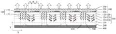
本实施例提供一种背光模组,图2A为本公开一实施例提供的背光模组 的局部示意图,如图2A所示,背光模组包括:导光结构100、光源层200 以及取光结构300。导光结构100包括导光板110以及体光栅层120,体光 栅层120包括呈阵列排布的多个体光栅部121以及位于相邻的体光栅部121 之间的导光部122。光源层200设置在导光板110主板面上,并且导光板110 设置在光源层200的出光侧,体光栅层120设置在导光板110远离光源层200 的一侧,取光结构300设置在导光结构100远离光源层200的一侧。导光结 构100的折射率大于光源层200以及取光结构300的折射率。光源层200包 括呈阵列排布的多个光源210,光源210在体光栅层120的正投影落入体光 栅部121内,体光栅部121被配置为将入射到体光栅层120的光束导入导光 部122和导光板110,且导入导光部122和导光板110的光束在导光板110 所在平面的入射角度不小于导光结构100的全反射临界角。而体光栅层120 中的导光部122被配置为使由导光板110全反射到体光栅层120中的光束继 续进行全反射传播。This embodiment provides a backlight module. FIG. 2A is a partial schematic diagram of the backlight module provided by an embodiment of the disclosure. As shown in FIG. 2A , the backlight module includes: a
本实施例中由于被体光栅层导入导光部和导光板的光束在导光板所在 平面的入射角度不小于导光结构的全反射临界角,因此,导入导光部和导光 板的光束会在导光结构中进行全反射传播,并由取光结构均匀取出。本公开 实施例提供的背光模组,一方面,可以使光能得到充分利用,并且,由于对 光源之间的间距没有特殊要求,在满足整体亮度的前提下,可以减少光源的 数量,降低成本;另一方面,该背光模组中的光源不需要混光高度,从而可 以有效降低背光模组的厚度。In this embodiment, since the incident angle of the light beam guided by the volume grating layer into the light guide portion and the light guide plate on the plane where the light guide plate is located is not less than the critical angle of total reflection of the light guide structure, the light beam guided into the light guide portion and the light guide plate will be at The total reflection propagation is carried out in the light guide structure, and is uniformly taken out by the light extraction structure. The backlight module provided by the embodiments of the present disclosure can, on the one hand, make full use of light energy, and, since there is no special requirement for the spacing between light sources, on the premise of satisfying the overall brightness, the number of light sources can be reduced and costs can be reduced On the other hand, the light source in the backlight module does not need a light mixing height, so that the thickness of the backlight module can be effectively reduced.
需要说明的是,“呈阵列排布的多个体光栅部”以及“呈阵列排布的多 个光源”中的“阵列排布”包括一维阵列排布或二维阵列排布。It should be noted that the "array arrangement" in "a plurality of volume grating portions arranged in an array" and "a plurality of light sources arranged in an array" includes a one-dimensional array arrangement or a two-dimensional array arrangement.
例如,图2B为图2A示出的背光模组的体光栅层的局部平面示意图, 如图2B所示,多个体光栅部121以及多个光源210呈二维阵列排布,且导 光部122围绕体光栅部121设置。导光部122在平行于光源层200所在平面 的平面上围绕体光栅部121,即,导光部122在XZ平面上围绕体光栅部121。 由于体光栅层120中不存在光源210,因此,图2B中正投影落入体光栅部 121内的光源210用虚线框表示。需要说明的是,图2B中相邻光源之间的 距离仅是示意性,实际上相邻的光源之间的距离很小。For example, FIG. 2B is a partial plan view of the volume grating layer of the backlight module shown in FIG. 2A . As shown in FIG. 2B , a plurality of
例如,图2C为图2A示出的另一示例中的背光模组的体光栅层的局部 平面示意图,如图2C所示,光源210、体光栅部121以及导光部122的平 面形状均为条形,且沿X方向,体光栅部121与导光部122交替设置,即, 多个体光栅部121以及多个光源210呈一维阵列排布(沿X方向阵列排布)。 需要说明的是,本示例中的光源为条状光源,且该条状光源沿Z方向延伸, 沿X方向排列。采用条状光源可以使本示例提供的背光模组的出射光更均 匀。For example, FIG. 2C is a schematic partial plan view of the volume grating layer of the backlight module in another example shown in FIG. 2A . As shown in FIG. 2C , the plane shapes of the
例如,本实施例中的光源210在体光栅层120的正投影落入体光栅部121 内,包括:光源210在体光栅层120的正投影与体光栅部121完全重合,或 者光源210在体光栅层120的正投影仅为体光栅部121的一部分,本实施例 对此不做限制。For example, the orthographic projection of the
需要说明的是,导光结构100中的体光栅层120的导光部122的折射率 与导光板110的折射率相等,这里的“相等”包括大致相等和完全相等。It should be noted that the refractive index of the
例如,光源层200中的光源210为准直光源。例如,光源层200中包括 的多个光源210为点阵光源,点阵光源可以包括点阵发光二极管(LED)与 准直透镜阵列的结合,也可以包括点阵有机发光二极管(OLED)与准直透 镜阵列的结合。本实施例对此不作限制,例如,还可以通过其他方式获取准 直光源。For example, the
例如,如图2A所示,本公开实施例提供的背光模组还包括:驱动电路 500,与多个光源210相连,被配置为调节多个光源210中的每个光源210 的发光强度,通过驱动电路500控制某一区域的光源210不发光,即,使该 区域处于0灰阶区域,可降低该区域的背光亮度。这里的驱动电路500仅是 示意性示图,对驱动电路500的具体电路排线方式不做限定,可根据实际情 况设置。例如,驱动电路500可以为薄膜晶体管(TFT),以实现局部动态 背光系统对每个光源210发光强度的动态调节。因此,本实施例还可以配合 液晶显示装置(LCD)进行局部动态调光,以减少功耗,延长光源的使用寿 命。For example, as shown in FIG. 2A , the backlight module provided by the embodiment of the present disclosure further includes: a driving
例如,光源210之间的间距可以为1-50mm,本实施例包括但不限于此, 光源之间的具体距离可根据产品设计中背光功耗与局部动态背光调控精细 程度之间的平衡决定。For example, the distance between the
例如,图3A为图2A示出的背光模组中的第一体光栅层中的第一体光 栅部沿XY平面所截的截面示意图,如图2A和图3A所示,体光栅层120 包括:第一体光栅层123,第一体光栅层123包括第一体光栅部1231,第一 体光栅部1231包括第一光栅条纹面1211。第一体光栅部1231被配置为仅将 入射光束中的第一颜色的光,例如红光,导入导光板110和导光部122中, 而除第一颜色的光以外的其他光束可以透过第一体光栅部1231并沿原入射 光束的方向继续传播。For example, FIG. 3A is a schematic cross-sectional view of the first volume grating portion of the first volume grating layer in the backlight module shown in FIG. 2A taken along the XY plane. As shown in FIGS. 2A and 3A , the
例如,如图3A所示,第一体光栅部1231即为布拉格光栅结构(也称三 维光栅),这种光栅结构沿某一方向的折射率是周期变化的,图3A以面间距 为d1的深色条纹面表示体光栅部的光栅周期,该深色条纹面即为第一光栅条 纹面1211。该深色条纹面也为透光面,且该深色条纹面中材料的折射率大于 周围无条纹面中材料的折射率。第一光栅条纹面1211位于第一体光栅部 1231中的入射光束的入射方向与出射光束的出射方向之间的夹角的角平分 线上,这里入射光束的入射方向以及出射光束的出射方向表示一种矢量方向。例如,本实施例中,第一光栅条纹面1211位于第一体光栅部1231中的 入射光束的延长线与出射光束之间的夹角的角平分线上。第一光栅条纹面 1211与入射光束的方向的夹角为θ1(锐角)即为入射光在第一光栅条纹面 1211上的掠射角i。For example, as shown in FIG. 3A , the first
本实施例提供的第一体光栅部1231为反射式体布拉格光栅结构,光束 入射到第一体光栅部1231后发生衍射,当入射光的掠射角i满足 2*n*d1*sini=λα1(布拉格定律)的关系式时,将在衍射光与第一光栅条纹面 1211的夹角为i的方向得到衍射极大。式中的n为第一体光栅部1231中非 条纹面的白色区域的折射率,也即是体光栅层120中导光部122的折射率(即 导光结构100的折射率)。式中的λα1为衍射光与第一光栅条纹面1211的夹 角为i的方向发生衍射极大的光束的波长。因此,当某一波长的入射光在第 一光栅条纹面1211的掠射角和衍射光与第一光栅条纹面1211的夹角相等, 即均为i时,可在衍射光与第一光栅条纹面1211的夹角为i的方向得到衍射 极大,而其他不满足上述波长条件的光束将透过第一体光栅部1231,并继续 沿入射光束的方向传播。The first
例如,如图3A所示,由于入射光的掠射角和衍射光与第一光栅条纹面 1211的夹角相等,如果把第一光栅条纹面1211看作反射镜面,则只有当相 邻条纹面的反射光程差均满足同相相加的条件,即布拉格条件(光程差等于 光波的一个波长)才能使衍射光达到极强,由此,第一体光栅部1231起到 了选择性反射的作用,即,第一体光栅部1231可以选择将特定波长的光束 导入导光板。For example, as shown in FIG. 3A, since the grazing angle of the incident light and the angle between the diffracted light and the first
例如,当入射到第一体光栅部1231的第一颜色的光,例如,红光波长λR满足2*n*d1*sini=λR时,第一体光栅部1231被配置为仅将入射光束中的红光 导入导光板110中。这里红光波长既可以指国际照明委员会(CIE)规定中 的红绿蓝(RGB)三原色中的红光的波长;也可以指红光波段中的主峰峰值 的波长,本实施例对此不作限制。For example, when the light of the first color, eg, the red light wavelength λR incident on the first
例如,如图3A所示,从第一体光栅部1231出射的衍射光与第一体光栅 部1231出光面的法线的夹角为α1,根据几何定律,α1=π-2*θ1。导光结构的 全反射临界角C满足:C=arcsin(n'/n)(全反射定律),其中的n'为导光结构 周围介质的折射率,例如,n'可以为光源层的折射率和/或取光结构的折射率。 因此,C≤α1时,导入导光板的光束可以在导光结构中进行全反射传播,以使光能得到充分利用。For example, as shown in Fig. 3A, the angle between the diffracted light emitted from the first
例如,图3B为图2A示出的背光模组中的第二体光栅层中的第二体光 栅部沿XY平面所截的截面示意图,如图2A和图3B所示,第二体光栅层 124包括第二体光栅部1241,第二体光栅部1241包括第二光栅条纹面1212。 第二体光栅部1241被配置为仅将入射光束中的第二颜色的光,例如绿光导 入导光板和导光部中,而除第二颜色的光之外的其他波段的光束可以透过第 二体光栅部1241并沿原入射光束的方向继续传播。本实施例中的第二体光栅部1241的第二光栅条纹面1212与入射光束的夹角为θ2(锐角),从第二 体光栅部1241出射的衍射光与第二体光栅部1241出光面的法线的夹角为 α2。For example, FIG. 3B is a schematic cross-sectional view of the second volume grating part in the second volume grating layer in the backlight module shown in FIG. 2A taken along the XY plane. As shown in FIGS. 2A and 3B , the second volume grating layer 124 includes a second
例如,本实施例的一示例以第二体光栅部1241中的夹角θ2以及夹角α2 与第一体光栅部1231中的夹角θ1以及夹角α1相同。本实施例中的第二体 光栅部1241中相邻的第二光栅条纹面1212之间的面间距为d2,本示例以面 间距d2与第一体光栅部1231中的第二光栅条纹面1212之间的面间距d1不 相同,并且入射到第二体光栅部1241的第二颜色的光,例如绿光波长λG满 足2*n*d2*sini=λG,因此,第二体光栅部1241被配置为仅将入射光束中的绿光导入导光板和导光部中。这里绿光波长指国际照明委员会(CIE)规定中 的红绿蓝(RGB)三原色中的绿光的波长;也可以指绿光波段中的主峰峰值 的波长,本实施例对此不作限制。For example, in an example of this embodiment, the included angle θ2 and the included angle α2 in the second
例如,图3C为图2A示出的背光模组中的第二体光栅层中的第三体光 栅部沿XY平面所截的截面示意图,如图2A和图3C所示,第三体光栅层 125包括第三体光栅部1251,第三体光栅部1251包括第三光栅条纹面1213。 第三体光栅部1251被配置为仅将入射光束中的第三颜色的光,例如蓝光导 入导光板和导光部中。本实施例中的第三体光栅部1251的第三光栅条纹面 1213与入射光束的夹角为θ3(锐角),从第三体光栅部1251出射的衍射光 与第三体光栅部1251出光面的法线的夹角为α3。For example, FIG. 3C is a schematic cross-sectional view of the third volume grating part in the second volume grating layer in the backlight module shown in FIG. 2A taken along the XY plane. As shown in FIGS. 2A and 3C , the third volume grating layer 125 includes a third
例如,本实施例的一示例以第三体光栅部1251中的夹角θ3以及夹角α3 与第一体光栅部1231(第二体光栅部1241)中的夹角θ1(θ2)以及夹角α1 (α2)相同。本实施例中的第三体光栅部1251中相邻的第三光栅条纹面1213 之间的间距为d3,本示例以面间距d3与第一体光栅部1231(第二体光栅部 1241)中的第一光栅条纹面1211(第二光栅条纹面1212)之间的面间距d1(d2)不相同,并且入射到第三体光栅部1251的第三颜色的光,例如蓝光 波长λB满足2*n*d3*sini=λB,因此,第三体光栅部1251被配置为仅将入射 光束中的蓝光导入导光板和导光部中。这里蓝光波长指国际照明委员会 (CIE)规定中的红绿蓝(RGB)三原色中的蓝光的波长;也可以指蓝光波 段中的主峰峰值的波长,本实施例对此不作限制。For example, in an example of this embodiment, the included angle θ3 and the included angle α3 in the third
因此,本实施例中的上述示例可以给定从每个体光栅部出射的衍射光与 相应的体光栅部出光面的法线的夹角均为α,即α1=α2=α3=α,与此同时, 每个体光栅部中的光栅条纹面与入射光束的夹角为均θ(锐角),即 θ1=θ2=θ3=θ,从而通过设计每个体光栅部的光栅条纹周期以实现对不同波段 光束的反射。Therefore, in the above example in this embodiment, it can be given that the angle between the diffracted light emitted from each volume grating portion and the normal of the light-emitting surface of the corresponding volume grating portion is α, that is, α1=α2=α3=α, and this At the same time, the angle between the grating fringe surface in each volume grating part and the incident beam is equal to θ (acute angle), that is, θ1=θ2=θ3=θ, so that the grating fringe period of each volume grating part can be designed to realize different wavelength beams. reflection.
例如,当本实施例中的光源210采用准直光源时,当光束中的红光、绿 光以及蓝光为国际照明委员会(CIE)规定中的红绿蓝(RGB)三原色中的 红光、绿光以及蓝光时,经过第三体光栅部1251后,没有光束从第三体光 栅部1251射出;当光束中的红光、绿光以及蓝光满足布拉格衍射定律的波 长取各波段中的主峰峰值的波长,且各波段的半高宽宽度不够窄时,光源210 出射的光经过第三体光栅部1251后,依然有光束射从第三体光栅部1251射出。For example, when the
例如,本实施例提供的导光板110的厚度不大于1mm。For example, the thickness of the
例如,本实施例提供的第一体光栅层123的厚度为5-20μm,第二体光 栅层124的厚度为5-20μm,第三体光栅层125的厚度为5-20μm。因此, 本实施例提供的导光结构的厚度不大于1.06mm。For example, the thickness of the first volume grating layer 123 provided in this embodiment is 5-20µm, the thickness of the second volume grating layer 124 is 5-20µm, and the thickness of the third volume grating layer 125 is 5-20µm. Therefore, the thickness of the light guide structure provided in this embodiment is not greater than 1.06 mm.
由上述实施例可知,光束入射到体光栅层后可以在导光结构中进行全反 射传播,因此背光模组中不需要设置较高的混光高度。与一般的需要设置混 光高度的直下式背光模组中的混光高度为2.64cm相比,本实施例中的导光 结构的厚度仅为毫米量级,能够大大降低背光模组的厚度,同时也可以使光 能得到充分的利用。It can be known from the above embodiment that the light beam can be totally reflected and propagated in the light guide structure after incident on the volume grating layer, so it is not necessary to set a high light mixing height in the backlight module. Compared with the light mixing height of 2.64 cm in the general direct type backlight module that needs to set the light mixing height, the thickness of the light guide structure in this embodiment is only in the order of millimeters, which can greatly reduce the thickness of the backlight module. At the same time, the light energy can be fully utilized.
例如,如图2A所示,本公开实施例提供的背光模组还包括反射层400, 设置在光源层200远离导光结构100的一侧。例如,反射层400可以为金属 膜层,被配置为反射从导光结构100面向光源层200一侧的表面出射到反射 层400的光束,提高光能的利用率。For example, as shown in FIG. 2A , the backlight module provided by the embodiment of the present disclosure further includes a
例如,如图2A所示,取光结构300包括设置在导光结构100远离光源 层200一侧表面的网点膜310。例如,网点膜310的材料可以与导光结构100 材料相同,网点膜310中分布有凹凸结构的网点,例如,网点在平行于导光 结构100的平面截取的最大尺寸可以为0.1-1mm,本实施例包括但不限于此。 例如,网点膜310也可以是在体光栅层120远离光源层200一侧的表面设置 的凹凸结构。For example, as shown in FIG. 2A , the
为了从导光结构100中均匀取光,从体光栅部121的出光侧远离体光栅 部121且平行于导光板110主平面的方向上,相邻的光源210之间的网点膜 310中的网点的分布密度设置为由小到大变化。本实施例以被体光栅层120 导入导光板110以及导光部122的光沿X方向进行全反射传播为例进行描 述,沿X方向,网点膜310中的网点分布密度呈周期性变化。In order to uniformly extract light from the
例如,沿X方向,在相邻的光源210之间,网点膜310中的网点的分布 密度由小到大,即网点的分布数量由少到多。因此,沿X方向,网点膜310 中的网点的分布密度变化规律以位于相邻的两个光源210之间的网点的分布 密度为一个周期而周期性的变化。网点膜310中的网点分布密度小的位置相 对于网点分布密度大的位置,取出的光较少。For example, along the X direction, between adjacent
例如,以图2A中位于A区域、B区域以及C区域中的网点膜310为例 进行描述,由A区域到C区域,网点膜310中的网点分布密度由小到大变 化,在导光结构100中传播的光在传播到网点膜310时,由于每个区域的网 点膜310都会取出一部分光,因此由A区域到C区域的方向,导光结构100 中的光线的密度由大到小变化。因而,网点膜310中网点的分布密度规律配 合导光结构100中的光线密度的变化规律,网点膜310可以从位于A区域、 B区域以及C区域中的导光结构100中取出能量大致相同的光以实现均匀取 光的作用。For example, taking the
例如,网点膜310还可以为特定的一维、或者二维光栅结构等,本实施 例对此不作限制,网点膜主要针对具体的光源和体光栅层的出光情况进行设 计,以实现背光光强的均匀分布。For example, the
例如,由于本实施例提供的背光模组中的光束沿X方向进行全反射传 播,因此,在垂直于XY面的方向(如图2B所示的示例中的Z方向),位于 相邻的光源210之间的网点膜310可以设置均匀分布的网点,也可以不设置 网点,本实施例对此不作限制。另外,位于体光栅部121的网点膜310中既 可以设置网点也可以不设置,本实施例对此不作限制。For example, since the light beam in the backlight module provided in this embodiment is totally reflected and propagated along the X direction, in the direction perpendicular to the XY plane (the Z direction in the example shown in FIG. 2B ), the adjacent light source The
例如,如图2A所示,取光结构300还包括设置在网点膜310远离导光 结构100的一侧扩散膜320。例如,扩散膜320可以包括一个高透过率的聚 合物(如聚碳酸酯、聚甲基丙稀酸甲酯、聚对苯二甲酸乙二醇酯等)基板和 掺杂在其中的散射颗粒(如二氧化钛等)。例如,扩散膜320也可以为多层 膜的叠层结构。穿过扩散膜320的光线会被其中的散射颗粒散射,使观察者 感知光是由扩散膜320表面直接提供的亮度分布。For example, as shown in FIG. 2A , the
例如,如图2A所示,取光结构300还包括设置在扩散膜320远离导光 结构100的一侧棱镜膜330。例如,棱镜膜330可以由一个具有尖角微棱镜 结构的棱镜层和一个基板层贴合而成,被配置为将大角度的光向小角度集 中,增加正视角的观看亮度。For example, as shown in FIG. 2A , the
例如,如图3A-图3C所示,本公开实施例的另一示例提供的第一体光 栅部1231中的第一光栅条纹面1211之间的面间距d1,第二体光栅部1241 中的第二光栅条纹面1212之间的面间距d2以及第三体光栅部1251中的第三 光栅条纹面1213之间的面间距d3均相等,即d1=d2=d3=d。由于光栅条纹面 与入射光束的方向的夹角θ(锐角)即为入射光在光栅条纹面的掠射角i,且 第一光栅条纹面1211与入射光束的方向的夹角θ1,第二光栅条纹面1212与入射光束的方向的夹角θ2以及第三光栅条纹面1213与入射光束的方向的 夹角θ3均不相等,因此,入射到第一体光栅部1231的第一颜色的光,例如 红光波长λR满足2*n*d*sinθ1=λR时,第一体光栅部1231被配置为仅将入射 光束中的红光导入导光板和导光部中;入射到第二体光栅部1241的第二颜 色的光,例如绿光波长λG满足2*n*d*sinθ2=λG时,第二体光栅部1241被配 置为仅将入射光束中的绿光导入导光板和导光部中;入射到第三体光栅部1251的第三颜色的光,例如蓝光波长λB满足2*n*d*sinθ3=λB时,第三体光 栅部1251被配置为仅将入射光束中的蓝光导入导光板和导光部中,由此, 本示例可以在给定每个体光栅部的光栅条纹周期为d,即d1=d2=d3=d的情况 下,通过设计每个体光栅部中光栅条纹面与入射光束的夹角以实现对不同波 段光束的反射。For example, as shown in FIGS. 3A-3C , another example of the embodiment of the present disclosure provides the interplanar spacing d1 between the first
需要说明的是,在本示例中由于每个体光栅部出射的衍射光与该体光栅 部出光面的法线的夹角α和每个体光栅部的光栅条纹面与入射光束的夹角θ 之间的关系满足α=π-2*θ,所以在设计每个体光栅部中光栅条纹面与入射光 束的夹角θ时应保证导光结构的全反射临界角C≤α,即,给定的每个体光 栅部的光栅条纹周期d应保证导光结构的全反射临界角C≤α。It should be noted that in this example, the angle α between the diffracted light emitted by each volume grating part and the normal to the light-emitting surface of the volume grating part and the angle θ between the grating fringe surface of each volume grating part and the incident beam are The relationship satisfies α=π-2*θ, so when designing the angle θ between the grating fringe surface and the incident light beam in each volume grating part, the total reflection critical angle C≤α of the light guide structure should be ensured, that is, for each given volume The grating fringe period d of the individual grating portion should ensure that the total reflection critical angle C≤α of the light guide structure.
例如,如图3A-图3C所示,本公开实施例的另一示例提供的每个体光 栅部的光栅条纹周期d可以均不相同,并且每个体光栅部中光栅条纹面与入 射光束的夹角θ可以也均不相同,在保证导光结构的全反射临界角C≤α的 前提下,通过对d和θ的灵活设计以实现对不同波段光束的反射。For example, as shown in FIGS. 3A-3C , the grating fringe period d of each volume grating portion provided by another example of the present disclosure may be different, and the included angle between the grating fringe surface in each volume grating portion and the incident light beam θ can also be different. On the premise of ensuring the total reflection critical angle C≤α of the light guide structure, the flexible design of d and θ can realize the reflection of light beams in different wavelength bands.
综上所述,本公开实施例可以通过对体光栅部的光栅条纹周期,或者体 光栅部包括的光栅条纹面与入射光束的夹角至少之一的调节,以实现体光栅 部被配置为将特定波长的光束导入导光部和导光板。也就是说,第一光栅条 纹面、第二光栅条纹面以及第三光栅条纹面中,光栅条纹周期和光栅条纹面 与入射光束的夹角的至少之一不同。To sum up, in the embodiments of the present disclosure, by adjusting at least one of the grating fringe period of the volume grating portion or the angle between the grating fringe surface included in the volume grating portion and the incident light beam, the volume grating portion can be configured to Light beams with specific wavelengths are guided into the light guide portion and the light guide plate. That is, in the first grating fringe surface, the second grating fringe surface and the third grating fringe surface, at least one of the grating fringe period and the angle between the grating fringe surface and the incident light beam is different.
实施例二Embodiment 2
本实施例提供一种背光模组的制作方法,图4为本公开一实施例提供的 背光模组的制作方法的示意性流程图,如图4所示,制作方法包括:The present embodiment provides a method for manufacturing a backlight module, and FIG. 4 is a schematic flowchart of a method for manufacturing a backlight module provided by an embodiment of the disclosure. As shown in FIG. 4 , the manufacturing method includes:
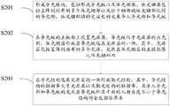
S201:形成导光结构,包括形成导光板以及体光栅层,体光栅层包括呈 阵列排布的多个体光栅部以及位于相邻的体光栅部之间的导光部,体光栅部 被配置为将特定波长的光束导入导光部和导光板;S201: Forming a light guide structure, including forming a light guide plate and a volume grating layer, the volume grating layer includes a plurality of volume grating parts arranged in an array and light guide parts located between adjacent volume grating parts, and the volume grating parts are configured as Direct the light beam of a specific wavelength into the light guide part and the light guide plate;
S202:在导光板的主板面上设置光源层,导光板位于光源层的出光侧, 体光栅层形成在导光板远离光源层的一侧,其中,光源层包括呈阵列排布的 多个光源,光源在体光栅层的正投影落入体光栅部内;S202: a light source layer is arranged on the main board surface of the light guide plate, the light guide plate is located on the light exit side of the light source layer, and the volume grating layer is formed on the side of the light guide plate away from the light source layer, wherein the light source layer includes a plurality of light sources arranged in an array, The orthographic projection of the light source on the volume grating layer falls into the volume grating part;
S203:在导光结构远离光源层的一侧形成取光结构,其中,导光结构的 折射率大于光源层以及取光结构的折射率,且导入导光部和导光板的光束在 导光板所在平面的入射角度不小于导光结构的全反射临界角。S203: forming a light extraction structure on the side of the light guide structure away from the light source layer, wherein the refractive index of the light guide structure is greater than the refractive index of the light source layer and the light extraction structure, and the light beam introduced into the light guide part and the light guide plate is at the location of the light guide plate The incident angle of the plane is not less than the critical angle of total reflection of the light guide structure.
采用本实施例提供的背光模组的制作方法,背光模组中的体光栅结构可 以将光源发出的入射光导入导光板和导光部,导入导光板和导光部的光束在 导光结构中进行全反射传播,并由取光结构均匀取出,一方面可以使光能得 到充分利用,另一方面,该背光模组中的光源不需要混光高度,从而有效降 低背光模组的厚度。By using the manufacturing method of the backlight module provided in this embodiment, the volume grating structure in the backlight module can guide the incident light emitted by the light source into the light guide plate and the light guide portion, and the light beams introduced into the light guide plate and the light guide portion are in the light guide structure. Carrying out total reflection propagation and uniformly taking out the light extraction structure, on the one hand, the light energy can be fully utilized, on the other hand, the light source in the backlight module does not need a light mixing height, thereby effectively reducing the thickness of the backlight module.
例如,多个体光栅部以及多个光源呈二维阵列排布,且导光部围绕体光 栅部设置。For example, a plurality of volume grating parts and a plurality of light sources are arranged in a two-dimensional array, and the light guide parts are arranged around the volume grating part.
例如,光源、体光栅部以及导光部的平面形状均为条形,且体光栅部与 导光部交替设置,即多个体光栅部以及多个光源呈一维阵列排布。For example, the plane shapes of the light source, the volume grating portion and the light guide portion are all stripes, and the volume grating portion and the light guide portion are alternately arranged, that is, a plurality of volume grating portions and a plurality of light sources are arranged in a one-dimensional array.
例如,光源层中的光源为准直光源。例如,光源层中包括的多个光源为 点阵光源,点阵光源可以包括点阵发光二极管(LED)与准直透镜阵列的结 合,也可以包括点阵有机发光二极管(OLED)与准直透镜阵列的结合等, 本实施例对此不作限制。For example, the light sources in the light source layer are collimated light sources. For example, the plurality of light sources included in the light source layer are lattice light sources, and the lattice light sources may include a combination of lattice light emitting diodes (LEDs) and collimating lens arrays, or may include lattice organic light emitting diodes (OLEDs) and collimating lenses. The combination of arrays, etc., is not limited in this embodiment.
例如,体光栅层包括:第一体光栅层,第二体光栅层以及第三体光栅层。 第一体光栅层包括第一体光栅部,第一体光栅部包括第一光栅条纹面。第一 体光栅部被配置为仅将入射光束中的第一颜色的光,例如红光导入导光板和 导光部;第二体光栅层包括第二体光栅部,第二体光栅部包括第二光栅条纹 面。第二体光栅部被配置为仅将入射光束中的第二颜色的光,例如绿光导入 导光板和导光部;第三体光栅层包括第三体光栅部,第三体光栅部包括第三 光栅条纹面。第三体光栅部被配置为仅将入射光束中的第三颜色的光,例如蓝光导入导光板和导光部。For example, the volume grating layer includes: a first volume grating layer, a second volume grating layer and a third volume grating layer. The first volume grating layer includes a first volume grating portion, and the first volume grating portion includes a first grating fringe surface. The first volume grating part is configured to guide only the light of the first color in the incident light beam, such as red light, into the light guide plate and the light guide part; the second volume grating layer includes a second volume grating part, and the second volume grating part includes a Two grating fringe surfaces. The second volume grating part is configured to guide only the light of the second color in the incident light beam, such as green light, into the light guide plate and the light guide part; the third volume grating layer includes a third volume grating part, and the third volume grating part includes a third volume grating part Three-grating fringe surface. The third volume grating part is configured to guide only the light of the third color in the incident light beam, eg, blue light, into the light guide plate and the light guide part.
例如,在制作每个体光栅层时,形成体光栅部包括:由两束平面光波分 别在光折变材料的两侧进行照射曝光。这里的光折变材料指曝光后折射率产 生变化的材料。例如,光折变材料可以包括掺铁铜铌酸锂晶体等材料,本实 施例对此不作限制。两束平面光波在光折变材料内发生干涉并形成三维干涉 条纹,即为本实施例中的体光栅部中的光栅条纹面,形成体光栅部后的光折 变材料即为本实施例中的体光栅层。光栅条纹面中的材料折射率大于光栅条 纹面区域以外的材料折射率。For example, when fabricating each volume grating layer, forming the volume grating part includes: irradiating and exposing two sides of the photorefractive material respectively by two plane light waves. The photorefractive material here refers to a material whose refractive index changes after exposure. For example, the photorefractive material may include materials such as iron-doped copper lithium niobate crystal, which is not limited in this embodiment. Two beams of plane light waves interfere in the photorefractive material and form three-dimensional interference fringes, which is the grating fringe surface in the volume grating part in this embodiment, and the photorefractive material after forming the volume grating part is in this embodiment. volume grating layer. The refractive index of the material in the grating fringe surface is greater than the refractive index of the material outside the grating fringe surface area.
例如,每个体光栅部均为布拉格光栅结构(也称三维光栅),这种光栅 结构沿某一方向的折射率是周期变化的。每个体光栅部的光栅条纹周期为d, 体光栅部中的光栅条纹面位于体光栅部中的入射光束的入射方向与出射光 束的出射方向之间的夹角的角平分线上,且光栅条纹与入射光束的方向的夹 角θ(锐角)即为入射光在第一光栅条纹面上的掠射角i。从体光栅部出射的 衍射光与体光栅部出光面的法线的夹角为α,根据几何定律,α=π-2*θ。本实 施例提供的体光栅部为反射式体布拉格光栅结构,光束入射到体光栅部后发 生衍射,当入射光的掠射角满足2*n*d*sini=λ(布拉格定律)的关系式时, 衍射光将在与光栅条纹面的夹角为i的方向得到衍射极大。式中的n为体光 栅部中非光栅条纹面的区域的折射率,也即是体光栅层中导光部的折射率 (即导光结构的折射率)。式中的λ为衍射光在与光栅条纹面夹角为i的方向 发生衍射极大的光束的波长。因此,当某一波长的入射光在光栅条纹面的掠 射角和衍射光与光栅条纹面的夹角相等,即均为i时,可在衍射光与光栅条 纹面的夹角i的方向得到衍射极大,而其他不满足上述波长条件的光束将透 过体光栅部,并继续沿入射光束的方向传播。由布拉格定律可知每个体光栅 部中的光栅条纹面与入射光束的夹角θ以及每个体光栅部的光栅条纹周期d 对于实现不同波段光束的反射起了决定作用,因此在制作体光栅层时可以通 过对d和θ的要求进行加工以形成满足需要的光栅条纹面。For example, each volume grating part is a Bragg grating structure (also called a three-dimensional grating), and the refractive index of this grating structure in a certain direction varies periodically. The grating fringe period of each volume grating part is d, the grating fringe surface in the volume grating part is located on the angle bisector of the angle between the incident direction of the incident light beam and the outgoing direction of the outgoing light beam in the volume grating part, and the grating fringes are The included angle θ (acute angle) with the direction of the incident light beam is the grazing angle i of the incident light on the fringe surface of the first grating. The angle between the diffracted light emitted from the volume grating part and the normal line of the light-emitting surface of the volume grating part is α, and according to the geometric law, α=π-2*θ. The volume grating part provided in this embodiment is a reflective volume Bragg grating structure. After the light beam is incident on the volume grating part, diffraction occurs. When the grazing angle of the incident light satisfies the relationship of 2*n*d*sini=λ (Bragg's law) When , the diffracted light will get a diffraction maximum in the direction of the included angle i with the grating fringe surface. In the formula, n is the refractive index of the non-grating fringe area in the volume grating portion, that is, the refractive index of the light guide portion in the volume grating layer (that is, the refractive index of the light guide structure). In the formula, λ is the wavelength of the diffracted light beam with the diffraction maximum in the direction of the angle i with the grating fringe plane. Therefore, when the grazing angle of the incident light of a certain wavelength on the grating fringe surface and the angle between the diffracted light and the grating fringe surface are equal, that is, when they are both i, it can be obtained in the direction of the angle i between the diffracted light and the grating fringe surface. Diffraction is extremely large, and other light beams that do not meet the above wavelength conditions will pass through the volume grating section and continue to propagate in the direction of the incident light beam. According to Bragg's law, it can be known that the angle θ between the grating fringe plane in each volume grating part and the incident light beam and the grating fringe period d of each volume grating part play a decisive role in realizing the reflection of light beams in different wavelength bands. Therefore, when fabricating the volume grating layer, it can be By processing the requirements of d and θ, the grating fringe surface that meets the requirements can be formed.
例如,形成的第一体光栅层的厚度为5-20μm,形成的第二体光栅层的 厚度为5-20μm,形成的第三体光栅层的厚度为5-20μm。For example, the first volume grating layer is formed to have a thickness of 5-20 µm, the second volume grating layer is formed to have a thickness of 5-20 µm, and the third volume grating layer is formed to have a thickness of 5-20 µm.
例如,导光结构中的导光板的厚度不大于1mm。因此,本实施例提供 的导光结构的厚度不大于1.06mm,由于,光束入射到体光栅层后可以在导 光结构中进行全反射传播,背光模组中不需要设置较高的混光高度,而本公 开实施例制作的导光结构的厚度较小,因此能够大大降低背光模组的厚度。For example, the thickness of the light guide plate in the light guide structure is not greater than 1 mm. Therefore, the thickness of the light guide structure provided in this embodiment is not greater than 1.06 mm. Since the light beam can be totally reflected and propagated in the light guide structure after incident on the volume grating layer, it is not necessary to set a high light mixing height in the backlight module. , and the thickness of the light guide structure fabricated in the embodiment of the present disclosure is relatively small, so the thickness of the backlight module can be greatly reduced.
例如,在光源层远离导光结构的一侧还可以设置反射层以提高光能的利 用率。For example, a reflective layer can also be provided on the side of the light source layer away from the light guide structure to improve the utilization rate of light energy.
例如,形成取光结构可以包括在导光结构远离光源层的一侧形成网点 膜。为了从导光结构中均匀取光,从体光栅部的出光侧远离体光栅部且平行 于导光板主平面的方向上,相邻的光源之间的网点膜中的网点的分布密度设 置为由小到大变化。For example, forming the light extraction structure may include forming a dot film on the side of the light guide structure away from the light source layer. In order to uniformly extract light from the light guide structure, the distribution density of the dots in the dot film between adjacent light sources is set to be Small to big changes.
例如,在网点膜远离导光结构的一侧形成扩散膜。例如,扩散膜可以包 括一个高透过率的聚合物(如聚碳酸酯、聚甲基丙稀酸甲酯、聚对苯二甲酸 乙二醇酯等)基板和掺杂在其中的散射颗粒(如二氧化钛等)。例如,扩散 膜也可以为多层膜的叠层结构。穿过扩散膜的光线会被其中的散射颗粒散 射,使观察者感知光是由扩散膜表面直接提供的亮度分布。For example, a diffusion film is formed on the side of the dot film away from the light guide structure. For example, the diffusion film may include a high transmittance polymer (such as polycarbonate, polymethyl methacrylate, polyethylene terephthalate, etc.) substrate and scattering particles ( such as titanium dioxide, etc.). For example, the diffusion film may be a laminated structure of a multilayer film. Light passing through the diffuser film is scattered by the scattering particles in it, causing the observer to perceive the light as a brightness distribution directly provided by the surface of the diffuser film.
例如,在扩散膜远离导光结构的一侧形成棱镜膜。例如,棱镜膜可以由 一个具有尖角微棱镜结构的棱镜层和一个基板层贴合而成,被配置为将大角 度的光向小角度集中,增加正视角的观看亮度。For example, a prism film is formed on the side of the diffusion film away from the light guide structure. For example, a prismatic film may be formed by laminating a prismatic layer with a sharp-angled microprism structure and a substrate layer, configured to concentrate light from a large angle to a small angle, increasing viewing brightness at positive viewing angles.
实施例三Embodiment 3
本实施例提供一种显示装置,该显示装置采用本公开的上述实施例提供 的背光模组,一方面,可以使光能得到充分利用,并且,由于对光源之间的 间距没有特殊要求,在满足整体亮度的前提下,可以减少光源的数量,降低 成本;另一方面,该背光模组中的光源不需要混光高度,从而可以有效降低 背光模组的厚度。This embodiment provides a display device. The display device adopts the backlight module provided by the above-mentioned embodiments of the present disclosure. On the one hand, light energy can be fully utilized. On the premise of satisfying the overall brightness, the number of light sources can be reduced and the cost can be reduced; on the other hand, the light sources in the backlight module do not need a light mixing height, so that the thickness of the backlight module can be effectively reduced.
例如,该显示装置可以为液晶显示装置以及包括该显示装置的电视、 数码相机、手机、手表、平板电脑、笔记本电脑、导航仪等任何具有显 示功能的产品或者部件,本实施例不限于此。For example, the display device may be a liquid crystal display device and any product or component with a display function including a TV, digital camera, mobile phone, watch, tablet computer, notebook computer, navigator, etc., which is not limited to this embodiment.
有以下几点需要说明:The following points need to be noted:
(1)除非另作定义,本公开实施例以及附图中,同一标号代表同一含 义。(1) Unless otherwise defined, in the embodiments of the present disclosure and the drawings, the same reference numerals represent the same meaning.
(2)本公开实施例附图中,只涉及到与本公开实施例涉及到的结构, 其他结构可参考通常设计。(2) In the drawings of the embodiments of the present disclosure, only the structures involved in the embodiments of the present disclosure are involved, and other structures may refer to general designs.
(3)为了清晰起见,在用于描述本公开的实施例的附图中,层或区域 被放大。可以理解,当诸如层、膜、区域或基板之类的元件被称作位于另一 元件“上”或“下”时,该元件可以“直接”位于另一元件“上”或“下”,或者可以 存在中间元件。(3) In the drawings for describing embodiments of the present disclosure, layers or regions are exaggerated for clarity. It will be understood that when an element such as a layer, film, region or substrate is referred to as being "on" or "under" another element, it can be "directly on" or "under" the other element, Or intermediate elements may be present.
以上所述,仅为本公开的具体实施方式,但本公开的保护范围并不局限 于此,任何熟悉本技术领域的技术人员在本公开揭露的技术范围内,可轻易 想到变化或替换,都应涵盖在本公开的保护范围之内。因此,本公开的保护 范围应以所述权利要求的保护范围为准。The above are only specific embodiments of the present disclosure, but the protection scope of the present disclosure is not limited to this. should be included within the scope of protection of the present disclosure. Therefore, the protection scope of the present disclosure should be based on the protection scope of the claims.
Claims (14)
Priority Applications (3)
| Application Number | Priority Date | Filing Date | Title |
|---|---|---|---|
| CN201710628510.7ACN107315280B (en) | 2017-07-28 | 2017-07-28 | Backlight module and its manufacturing method, display device |
| US16/097,503US10914884B2 (en) | 2017-07-28 | 2018-02-01 | Backlight module and manufacturing method thereof, display device and light guide device |
| PCT/CN2018/074950WO2019019598A1 (en) | 2017-07-28 | 2018-02-01 | Backlight module and method for manufacturing same, display device, and light guide device |
Applications Claiming Priority (1)
| Application Number | Priority Date | Filing Date | Title |
|---|---|---|---|
| CN201710628510.7ACN107315280B (en) | 2017-07-28 | 2017-07-28 | Backlight module and its manufacturing method, display device |
Publications (2)
| Publication Number | Publication Date |
|---|---|
| CN107315280A CN107315280A (en) | 2017-11-03 |
| CN107315280Btrue CN107315280B (en) | 2020-02-21 |
Family
ID=60169862
Family Applications (1)
| Application Number | Title | Priority Date | Filing Date |
|---|---|---|---|
| CN201710628510.7AActiveCN107315280B (en) | 2017-07-28 | 2017-07-28 | Backlight module and its manufacturing method, display device |
Country Status (3)
| Country | Link |
|---|---|
| US (1) | US10914884B2 (en) |
| CN (1) | CN107315280B (en) |
| WO (1) | WO2019019598A1 (en) |
Families Citing this family (9)
| Publication number | Priority date | Publication date | Assignee | Title |
|---|---|---|---|---|
| CN107315280B (en) | 2017-07-28 | 2020-02-21 | 京东方科技集团股份有限公司 | Backlight module and its manufacturing method, display device |
| CN107238979B (en)* | 2017-08-11 | 2020-04-10 | 京东方科技集团股份有限公司 | Light guide assembly, preparation method, backlight module and display device |
| CN108563061A (en)* | 2017-12-28 | 2018-09-21 | 重庆市中光电显示技术有限公司 | Backlight module |
| CN108224240A (en)* | 2018-01-12 | 2018-06-29 | 京东方科技集团股份有限公司 | Down straight aphototropism mode set and display device |
| CN108398830B (en)* | 2018-03-07 | 2021-08-31 | 京东方科技集团股份有限公司 | A backlight module and a liquid crystal display device |
| CN108287438B (en) | 2018-03-30 | 2020-11-27 | 京东方科技集团股份有限公司 | Backlight module and display device |
| CN109581750B (en)* | 2019-02-01 | 2021-08-31 | 京东方科技集团股份有限公司 | A backlight module and display device |
| TWI740355B (en)* | 2020-01-20 | 2021-09-21 | 尚立光電股份有限公司 | Light-guide optical element |
| JP7465826B2 (en)* | 2021-02-02 | 2024-04-11 | 株式会社日立エルジーデータストレージ | Light guide plate, light guide plate module and image display device |
Citations (1)
| Publication number | Priority date | Publication date | Assignee | Title |
|---|---|---|---|---|
| CN105301842A (en)* | 2015-11-24 | 2016-02-03 | 昆山龙腾光电有限公司 | Backlight module and display device using same |
Family Cites Families (9)
| Publication number | Priority date | Publication date | Assignee | Title |
|---|---|---|---|---|
| US20110141395A1 (en)* | 2008-07-22 | 2011-06-16 | Sharp Kabushiki Kaisha | Backlight unit and liquid crystal display device |
| CN101696785B (en)* | 2009-11-16 | 2011-01-05 | 上海交通大学 | Light guide plate with polarization function based on one-dimensional metal photon crystals |
| CN101699152B (en)* | 2009-11-16 | 2011-07-20 | 上海交通大学 | Two-dimensional metallic photonic crystal-based light guide plate with polarization function |
| CN103867965A (en)* | 2012-12-18 | 2014-06-18 | 鸿富锦精密工业(深圳)有限公司 | Backlight module |
| KR101342482B1 (en)* | 2013-04-30 | 2013-12-17 | 주식회사 제이에스컴패니 | Signal board |
| CN105700065B (en)* | 2016-04-22 | 2019-05-07 | 京东方科技集团股份有限公司 | Light guide plate, backlight module and display device |
| CN105700226A (en)* | 2016-04-25 | 2016-06-22 | 京东方科技集团股份有限公司 | Viewing angle control mechanism, light guide plate, backlight module, array substrate and display panel |
| CN105938271A (en)* | 2016-05-24 | 2016-09-14 | 江苏生辉光电科技有限公司 | Projection type holographic grating backlight structure |
| CN107315280B (en)* | 2017-07-28 | 2020-02-21 | 京东方科技集团股份有限公司 | Backlight module and its manufacturing method, display device |
- 2017
- 2017-07-28CNCN201710628510.7Apatent/CN107315280B/enactiveActive
- 2018
- 2018-02-01USUS16/097,503patent/US10914884B2/ennot_activeExpired - Fee Related
- 2018-02-01WOPCT/CN2018/074950patent/WO2019019598A1/ennot_activeCeased
Patent Citations (1)
| Publication number | Priority date | Publication date | Assignee | Title |
|---|---|---|---|---|
| CN105301842A (en)* | 2015-11-24 | 2016-02-03 | 昆山龙腾光电有限公司 | Backlight module and display device using same |
Also Published As
| Publication number | Publication date |
|---|---|
| WO2019019598A1 (en) | 2019-01-31 |
| CN107315280A (en) | 2017-11-03 |
| US10914884B2 (en) | 2021-02-09 |
| US20200326465A1 (en) | 2020-10-15 |
Similar Documents
| Publication | Publication Date | Title |
|---|---|---|
| CN107315280B (en) | Backlight module and its manufacturing method, display device | |
| CN108287438B (en) | Backlight module and display device | |
| US8817205B2 (en) | Display device and planar light source device | |
| JP5360172B2 (en) | Planar light source device and display device using the same | |
| CN107305265B (en) | Light guide plate, backlight module and display device | |
| CN111323982A (en) | Peep-proof film, backlight source and display device | |
| WO2011065052A1 (en) | Planar lighting device and display device having same | |
| JP5409901B2 (en) | Planar light source device and display device using the same | |
| US8251565B2 (en) | Illumination device and display device | |
| US9348081B2 (en) | Illumination device and display device | |
| CN106597599A (en) | Backlight module, display panel and display device | |
| US11391877B2 (en) | Backlight source and manufacturing method thereof, and display device | |
| CN101595409A (en) | Light outcoupling structure for lighting device | |
| JP2011014520A (en) | Lighting device and display | |
| KR101268960B1 (en) | backlight unit | |
| CN106647042B (en) | A kind of light source device and display device | |
| TW201915982A (en) | Spliced display apparatus | |
| CN104698678B (en) | Luminous flux control member, light emitting device and display device | |
| CN108885302B (en) | Lighting and Display Devices | |
| JP5601042B2 (en) | Planar light source device and display device | |
| CN113311530B (en) | Light source assembly and display device | |
| CN101761829A (en) | Backlight module and display device using same | |
| CN101126862A (en) | Side light-entering type backlight assembly | |
| JP2022546678A (en) | display system | |
| CN108279505B (en) | An optical cavity, an optical system and a display device |
Legal Events
| Date | Code | Title | Description |
|---|---|---|---|
| PB01 | Publication | ||
| PB01 | Publication | ||
| SE01 | Entry into force of request for substantive examination | ||
| SE01 | Entry into force of request for substantive examination | ||
| GR01 | Patent grant | ||
| GR01 | Patent grant |