CN107280735B - Repeatedly-usable ultrasonic surgical instrument - Google Patents
Repeatedly-usable ultrasonic surgical instrumentDownload PDFInfo
- Publication number
- CN107280735B CN107280735BCN201710602001.7ACN201710602001ACN107280735BCN 107280735 BCN107280735 BCN 107280735BCN 201710602001 ACN201710602001 ACN 201710602001ACN 107280735 BCN107280735 BCN 107280735B
- Authority
- CN
- China
- Prior art keywords
- button
- surgical instrument
- ultrasonic surgical
- slot
- sleeve
- Prior art date
- Legal status (The legal status is an assumption and is not a legal conclusion. Google has not performed a legal analysis and makes no representation as to the accuracy of the status listed.)
- Active
Links
Images


Classifications
- A—HUMAN NECESSITIES
- A61—MEDICAL OR VETERINARY SCIENCE; HYGIENE
- A61B—DIAGNOSIS; SURGERY; IDENTIFICATION
- A61B17/00—Surgical instruments, devices or methods
- A61B17/32—Surgical cutting instruments
- A61B17/320068—Surgical cutting instruments using mechanical vibrations, e.g. ultrasonic
- A—HUMAN NECESSITIES
- A61—MEDICAL OR VETERINARY SCIENCE; HYGIENE
- A61B—DIAGNOSIS; SURGERY; IDENTIFICATION
- A61B17/00—Surgical instruments, devices or methods
- A61B17/32—Surgical cutting instruments
- A61B17/320068—Surgical cutting instruments using mechanical vibrations, e.g. ultrasonic
- A61B17/320092—Surgical cutting instruments using mechanical vibrations, e.g. ultrasonic with additional movable means for clamping or cutting tissue, e.g. with a pivoting jaw
- A—HUMAN NECESSITIES
- A61—MEDICAL OR VETERINARY SCIENCE; HYGIENE
- A61B—DIAGNOSIS; SURGERY; IDENTIFICATION
- A61B17/00—Surgical instruments, devices or methods
- A61B17/34—Trocars; Puncturing needles
- A61B17/3417—Details of tips or shafts, e.g. grooves, expandable, bendable; Multiple coaxial sliding cannulas, e.g. for dilating
- A61B17/3421—Cannulas
- A61B17/3423—Access ports, e.g. toroid shape introducers for instruments or hands
- A—HUMAN NECESSITIES
- A61—MEDICAL OR VETERINARY SCIENCE; HYGIENE
- A61B—DIAGNOSIS; SURGERY; IDENTIFICATION
- A61B17/00—Surgical instruments, devices or methods
- A61B2017/00367—Details of actuation of instruments, e.g. relations between pushing buttons, or the like, and activation of the tool, working tip, or the like
- A—HUMAN NECESSITIES
- A61—MEDICAL OR VETERINARY SCIENCE; HYGIENE
- A61B—DIAGNOSIS; SURGERY; IDENTIFICATION
- A61B17/00—Surgical instruments, devices or methods
- A61B2017/0046—Surgical instruments, devices or methods with a releasable handle; with handle and operating part separable
- A—HUMAN NECESSITIES
- A61—MEDICAL OR VETERINARY SCIENCE; HYGIENE
- A61B—DIAGNOSIS; SURGERY; IDENTIFICATION
- A61B17/00—Surgical instruments, devices or methods
- A61B2017/00477—Coupling
- A—HUMAN NECESSITIES
- A61—MEDICAL OR VETERINARY SCIENCE; HYGIENE
- A61B—DIAGNOSIS; SURGERY; IDENTIFICATION
- A61B17/00—Surgical instruments, devices or methods
- A61B17/32—Surgical cutting instruments
- A61B17/320068—Surgical cutting instruments using mechanical vibrations, e.g. ultrasonic
- A61B17/320092—Surgical cutting instruments using mechanical vibrations, e.g. ultrasonic with additional movable means for clamping or cutting tissue, e.g. with a pivoting jaw
- A61B2017/320093—Surgical cutting instruments using mechanical vibrations, e.g. ultrasonic with additional movable means for clamping or cutting tissue, e.g. with a pivoting jaw additional movable means performing cutting operation
- A—HUMAN NECESSITIES
- A61—MEDICAL OR VETERINARY SCIENCE; HYGIENE
- A61B—DIAGNOSIS; SURGERY; IDENTIFICATION
- A61B17/00—Surgical instruments, devices or methods
- A61B17/32—Surgical cutting instruments
- A61B17/320068—Surgical cutting instruments using mechanical vibrations, e.g. ultrasonic
- A61B17/320092—Surgical cutting instruments using mechanical vibrations, e.g. ultrasonic with additional movable means for clamping or cutting tissue, e.g. with a pivoting jaw
- A61B2017/320094—Surgical cutting instruments using mechanical vibrations, e.g. ultrasonic with additional movable means for clamping or cutting tissue, e.g. with a pivoting jaw additional movable means performing clamping operation
Landscapes
- Health & Medical Sciences (AREA)
- Surgery (AREA)
- Life Sciences & Earth Sciences (AREA)
- Engineering & Computer Science (AREA)
- Heart & Thoracic Surgery (AREA)
- Nuclear Medicine, Radiotherapy & Molecular Imaging (AREA)
- Biomedical Technology (AREA)
- Medical Informatics (AREA)
- Molecular Biology (AREA)
- Animal Behavior & Ethology (AREA)
- General Health & Medical Sciences (AREA)
- Public Health (AREA)
- Veterinary Medicine (AREA)
- Mechanical Engineering (AREA)
- Dentistry (AREA)
- Pathology (AREA)
- Surgical Instruments (AREA)
Abstract
Description
Translated fromChinese技术领域technical field
本申请涉及一种外科手术器械,具体涉及一种可重复使用的超声手术器械。The present application relates to a surgical instrument, in particular to a reusable ultrasonic surgical instrument.
背景技术Background technique
随着微创外科手术的普及,超声刀已经成为一种常规的手术器械。超声刀通过超声频率发生器使刀头以一定的超声频率进行机械振荡,使组织内的水分子汽化、蛋白质氢键断裂、细胞崩解,从而使得组织被切开或者凝固,还可以使血管闭合。超声手术刀使组织切割和凝固止血同时完成,并具有较小的侧向热损伤。With the popularization of minimally invasive surgery, the ultrasonic knife has become a conventional surgical instrument. The ultrasonic knife makes the knife head mechanically oscillate at a certain ultrasonic frequency through the ultrasonic frequency generator, so that the water molecules in the tissue are vaporized, the protein hydrogen bonds are broken, and the cells are disintegrated, so that the tissue is cut or coagulated, and the blood vessels can also be closed. . The ultrasonic scalpel enables simultaneous tissue cutting and coagulation hemostasis with less lateral thermal damage.
超声手术刀系统主要由超声频率发生器、换能器和手术器械组成。其中,超声频率发生器发出振荡电信号,换能器将振荡电信号转换为机械振动,手术器械利用换能器的机械振动对组织进行切割和凝固止血。手术器械通常由刀杆、与刀头(刀杆头部的切割部位)构成夹持结构的夹钳、包围在刀杆外部的套管、握柄及抓持机构组成。刀杆将换能器产生的机械振动传递到刀头;刀头与夹钳配合夹持组织实现切割和凝固止血的功能;套管一方面将刀杆与外部隔离起到保护刀杆的作用,另一方面与夹钳构成连杆机构以带动夹钳的闭合与张开;握柄及抓持机构由医生手部握持,可操作夹钳张开闭合,且有开关可控制超声频率发生器开始或停止输出振荡电信号。The ultrasonic scalpel system is mainly composed of ultrasonic frequency generator, transducer and surgical instruments. Among them, the ultrasonic frequency generator sends out an oscillating electrical signal, the transducer converts the oscillating electrical signal into mechanical vibration, and the surgical instrument uses the mechanical vibration of the transducer to cut and coagulate tissue to stop bleeding. Surgical instruments are usually composed of a cutter bar, a clamp that forms a clamping structure with the cutter head (the cutting part of the cutter bar head), a sleeve surrounding the cutter bar, a handle and a gripping mechanism. The cutter bar transmits the mechanical vibration generated by the transducer to the cutter head; the cutter head cooperates with the clamp to hold the tissue to achieve the functions of cutting and coagulating hemostasis; on the one hand, the sleeve isolates the cutter bar from the outside to protect the cutter bar, On the other hand, it forms a link mechanism with the clamp to drive the closing and opening of the clamp; the handle and the grasping mechanism are held by the doctor's hand, and the clamp can be opened and closed, and there is a switch to control the ultrasonic frequency generator Start or stop the output of the oscillating electrical signal.
目前市场上主流的超声手术刀系统,如CN101035482 B(参考文献1)、CN106028979A(参考文献2)所公开的,其手术器械的套管由外套管和内套管组成,刀杆位于内套管之内。内外套管之间、内套管与刀杆之间的间隙比较小,但在一台手术完成之后,仍然会有一些血液或者组织液进入内外套管之间或者内套管与刀杆之间的间隙,由于间隙非常小且狭长,进入间隙之内的血液或者组织液很难被清洗干净。因此即便手术器械的结构与性能依然良好,也不能被再次重复使用,而只能作为一次性器械来使用,所以其使用成本非常高昂。The mainstream ultrasonic scalpel systems currently on the market, such as those disclosed in CN101035482 B (Reference 1) and CN106028979A (Reference 2), have surgical instruments whose sleeves are composed of an outer sleeve and an inner sleeve, and the knife bar is located in the inner sleeve. within. The gaps between the inner and outer casings, between the inner casing and the cutter bar are relatively small, but after an operation is completed, some blood or tissue fluid will still enter between the inner and outer casings or between the inner casing and the cutter bar. Gap, because the gap is very small and long, it is difficult to clean the blood or tissue fluid that enters the gap. Therefore, even if the structure and performance of the surgical instrument are still good, it cannot be reused again, but can only be used as a disposable instrument, so the use cost is very high.
为了让手术器械能够重复多次使用从而降低使用成本,CN202908793 U(参考文献3)、CN203988246 U(参考文献4)提出了相应的技术方案。CN202908793U(参考文献3)中将套管、刀杆、夹钳设计成一个可更换的组件结构,只能一次性使用,而其它的零部件可以多次重复使用。这样的设计虽然一定程度上降低了使用成本,但因为套管、刀杆、夹钳这些零部件的成本占据了手术器械成本的绝大多数,因此成本降低效果非常有限。CN203988246 U(参考文献4)中采取的技术方案是将套管和夹钳设计成可更换的组件,只能一次性使用,其它零部件包括刀杆都可以多次重复使用,能够有效降低使用成本。但是该技术方案涉及的零部件较多,采用的焊接、螺纹连接工艺也较多,实现起来比较复杂。In order to allow the surgical instrument to be reused many times and thus reduce the use cost, CN202908793 U (Reference 3) and CN203988246 U (Reference 4) propose corresponding technical solutions. In CN202908793U (Reference 3), the sleeve, the cutter bar, and the clamp are designed as a replaceable component structure, which can only be used once, while other components can be reused for many times. Although such a design reduces the cost of use to a certain extent, the cost reduction effect is very limited because the cost of parts such as sleeves, cutter bars, and clamps account for the vast majority of the cost of surgical instruments. The technical solution adopted in CN203988246 U (Reference 4) is to design the sleeve and the clamp as replaceable components, which can only be used once. . However, this technical solution involves many parts and adopts many welding and thread connection processes, which is more complicated to implement.
参考文献:references:
[1]CN101035482 B,发明名称为“超声外科器械”;[1] CN101035482 B, the name of the invention is "ultrasonic surgical instrument";
[2]CN106028979 A,发明名称为“用于超声外科器械的夹持臂特征结构”;[2] CN106028979 A, the name of the invention is "Characteristic structure of clamping arm for ultrasonic surgical instruments";
[3]CN202908793 U,发明名称为“可换刀杆的超声手术刀”;[3] CN202908793 U, the name of the invention is "ultrasonic scalpel with replaceable blade";
[4]CN203988246 U,发明名称为“一种可拆装的超声刀管快速对接装置”。[4] CN203988246 U, the name of the invention is "a detachable ultrasonic knife tube quick docking device".
发明内容SUMMARY OF THE INVENTION
为了解决上述技术问题,本申请提供一种可重复使用的超声手术器械,相对于现有技术具有结构简单、工艺实现容易、操作方便、成本低的优点。In order to solve the above technical problems, the present application provides a reusable ultrasonic surgical instrument, which has the advantages of simple structure, easy process realization, convenient operation and low cost compared with the prior art.
根据本申请的一方面,提供一种可重复使用的超声手术器械,包括套管组件、刀杆、基座及夹持驱动组件,所述套管组件包括设置在远端的夹钳、外套管和内套管,所述外套管、所述内套管均与所述刀杆同轴设置;所述夹钳近端设置有两个旋转轴,所述两个旋转轴的其中一个旋转轴与所述外套管旋转连接,另一个旋转轴和所述内套管旋转连接;所述套管组件可向着所述刀杆轴线的远端方向从所述基座及所述夹持驱动组件拆卸或向着所述刀杆轴线的近端方向安装在所述基座及所述夹持驱动组件上;所述外套管通过一个或一个以上的第一可拆卸结构与所述基座连接;所述内套管通过一个或一个以上的第二可拆卸结构与所述夹持驱动组件连接。According to an aspect of the present application, a reusable ultrasonic surgical instrument is provided, comprising a cannula assembly, a knife rod, a base and a clamping drive assembly, the cannula assembly including a clamp disposed at a distal end, an outer cannula and an inner sleeve, the outer sleeve and the inner sleeve are coaxially arranged with the cutter bar; the proximal end of the clamp is provided with two rotating shafts, and one of the two rotating shafts is The outer sleeve is rotatably connected, and the other rotating shaft is rotatably connected with the inner sleeve; the sleeve assembly can be detached from the base and the clamping drive assembly toward the distal direction of the axis of the cutter bar or It is installed on the base and the clamping drive assembly toward the proximal end of the axis of the cutter bar; the outer sleeve is connected to the base through one or more first detachable structures; the inner sleeve is connected to the base; The sleeve is connected to the clamp drive assembly through one or more second detachable structures.
在一个实施方式中,所述第一可拆卸结构由所述基座上的光孔、所述外套管上的螺纹孔及螺栓组成,所述螺栓可穿过所述基座上的光孔拧紧或者拧出所述外套管上的螺纹孔。In one embodiment, the first detachable structure is composed of a light hole on the base, a threaded hole on the outer sleeve, and a bolt, and the bolt can be screwed through the light hole on the base Or screw out the threaded holes on the outer sleeve.
在另一个实施方式中,所述第一可拆卸结构由所述基座上的螺纹孔、所述外套管上的光孔及螺栓组成,所述螺栓可拧紧或者拧出所述基座上的螺纹孔从而穿入或者退出所述外套管上的光孔。In another embodiment, the first detachable structure is composed of threaded holes on the base, light holes on the outer sleeve, and bolts, and the bolts can be tightened or unscrewed from the threaded holes on the base. The threaded hole thus penetrates or exits the light hole on the outer sleeve.
在另一个实施方式中,所述第一可拆卸结构由第一卡位槽、按钮、弹性元件和卡座组成;所述第一卡位槽由第一滑动槽及第一止位槽相互连接构成;所述按钮有一按钮轴线,且包括沿着所述按钮轴线方向分布并相互连接的安装段、止位段及拆卸段,所述弹性元件设置在按钮的按钮轴线方向上使得所述按钮能沿着所述按钮轴线方向在最高位和最低位之间运动;所述按钮的安装段与所述卡座及所述弹性元件连接,使得自然状态下所述按钮处于所述最高位,并能在外力的作用下克服所述弹性元件的弹力运动到所述最低位;所述按钮的止位段能嵌入所述第一止位槽,并能被所述第一止位槽约束垂直于所述按钮轴线方向的运动;所述按钮的拆卸段能在所述第一卡位槽内自由滑动。In another embodiment, the first detachable structure is composed of a first locking groove, a button, an elastic element and a card seat; the first locking groove is connected to each other by a first sliding groove and a first stop groove The button has a button axis, and includes an installation section, a stop section and a disassembly section that are distributed and interconnected along the button axis direction, and the elastic element is arranged in the button axis direction of the button so that the button can be The button moves between the highest position and the lowest position along the axis direction of the button; the installation section of the button is connected with the clip seat and the elastic element, so that the button is in the highest position in a natural state, and can Under the action of external force, it can overcome the elastic force of the elastic element and move to the lowest position; the stop section of the button can be inserted into the first stop slot, and can be constrained by the first stop slot to be perpendicular to the The button can move in the axial direction of the button; the disassembly section of the button can slide freely in the first locking groove.
进一步,所述第一卡位槽设置在所述基座上,所述按钮、弹性元件和卡座设置在所述外套管上。Further, the first clamping slot is arranged on the base, and the button, the elastic element and the clamping seat are arranged on the outer sleeve.
在一个实施方式中,所述第一卡位槽设置在所述外套管上,所述按钮、弹性元件和卡座设置所述基座上。In one embodiment, the first clamping groove is provided on the outer sleeve, and the button, the elastic element and the clamping seat are provided on the base.
进一步,卡座为基座或外套管上的具有一定高度的孔,按钮的安装段通过弹性元件安装在卡座内并能沿着所述孔在最高位和最低位之间移动。Further, the socket is a hole with a certain height on the base or the outer sleeve, and the installation section of the button is installed in the socket through an elastic element and can move between the highest position and the lowest position along the hole.
进一步,所述弹性元件一端压在按钮的安装段的底部,一端压在封闭卡座的底部的圆柱形零件上。Further, one end of the elastic element is pressed against the bottom of the installation section of the button, and the other end is pressed against the cylindrical part of the bottom of the closed cartridge.
在另一个实施方式中,所述按钮与卡座之间由卡扣和扣眼的结构连接,其中,扣眼的高度大于卡扣的高度,使得卡扣可沿按钮轴线方向在扣眼内活动,从而按钮可在最高位与最低位之间运动。In another embodiment, the button and the socket are connected by a structure of a buckle and a buttonhole, wherein the height of the buttonhole is greater than the height of the buckle, so that the buckle can move in the buttonhole along the axis direction of the button, so that the button Can move between the highest and lowest positions.
进一步,所述卡扣设置在卡座上,所述扣眼设置在按钮上;或者,所述卡扣设置在按钮上,所述扣眼设置在卡座上。Further, the buckle is arranged on the card seat, and the button hole is arranged on the button; or, the buckle is arranged on the button, and the button hole is arranged on the card seat.
进一步,所述弹性元件为圆柱弹簧、波簧或者其它弹性体。Further, the elastic element is a cylindrical spring, a wave spring or other elastic bodies.
在另一个实施方式中,所述第一滑动槽一部分与所述刀杆轴线平行,另一部分与所述刀杆轴线垂直;所述第一止位槽最大槽宽大于所述第一滑动槽最大槽宽。In another embodiment, a part of the first sliding groove is parallel to the axis of the tool shank, and the other part is perpendicular to the axis of the tool shank; the maximum width of the first stop groove is greater than the maximum width of the first sliding groove Slot width.
在上述任一实施方式中,所述第二可拆卸结构由第二卡位槽和搭扣结构组成。所述第二卡位槽由第二滑动槽及第二止位槽相互连接构成;所述搭扣结构能在所述第二滑动槽内自由滑动且能从所述第二滑动槽滑入所述第二止位槽内,并能被所述第二止位槽约束沿所述刀杆轴线方向的运动。In any of the above-mentioned embodiments, the second detachable structure is composed of a second retaining slot and a buckle structure. The second locking slot is formed by connecting a second sliding slot and a second stopping slot; the buckle structure can slide freely in the second sliding slot and can slide into the second sliding slot from the second sliding slot. The second stop groove can restrain the movement along the axis direction of the cutter bar by the second stop groove.
进一步,所述第二卡位槽位于所述内套管上,所述搭扣结构位于所述夹持驱动组件上。Further, the second locking groove is located on the inner sleeve, and the snap structure is located on the clamping drive assembly.
在另一个实施方式中,所述第二卡位槽位于所述夹持驱动组件上,所述搭扣结构位于所述内套管上。In another embodiment, the second locking groove is located on the clamping drive assembly, and the snap structure is located on the inner sleeve.
在一个实施方式中,所述第二滑动槽与所述刀杆轴线平行。In one embodiment, the second sliding groove is parallel to the axis of the shank.
进一步,所述第二止位槽与所述刀杆轴线垂直。Further, the second stop groove is perpendicular to the axis of the tool bar.
根据本申请的可重复使用的超声手术器械,套管组件与刀杆、基座及夹持驱动组件可拆卸地连接,在使用后方便拆卸开进行清洗,进而可重复使用,解决了市场上主流的超声手术器械使用后不容易清洗,不能重复使用的问题,能显著降低器械的使用成本。并且相对于参考文献3的可重复使用的超声系统,本申请的可重复使用的超声手术器械中可重复使用的部件增多从而进一步降低使用成本,相对于参考文献4,本申请在拆卸方便性、整体结构的可靠性、工艺实现的简便性等方面都有提升。总之,本申请相比于现有技术具有结构简单、成本低的优点。According to the reusable ultrasonic surgical instrument of the present application, the sleeve assembly is detachably connected to the cutter bar, the base and the clamping drive assembly, and can be easily disassembled for cleaning after use, and can be reused, which solves the problem of the mainstream in the market. The ultrasonic surgical instruments are not easy to clean after use and cannot be reused, which can significantly reduce the use cost of the instruments. And compared with the reusable ultrasonic system of
附图说明Description of drawings
图1为超声手术刀系统的示意图;Fig. 1 is the schematic diagram of ultrasonic scalpel system;
图2为根据本申请第一种实施方式的可重复使用的超声手术器械的示意图;2 is a schematic diagram of a reusable ultrasonic surgical instrument according to a first embodiment of the present application;
图3为图2中第二可拆卸结构的示意图;Fig. 3 is the schematic diagram of the second detachable structure in Fig. 2;
图4为根据本申请第二种实施方式的可重复使用的超声手术器械的示意图;4 is a schematic diagram of a reusable ultrasonic surgical instrument according to a second embodiment of the present application;
图5为图4中第一可拆卸结构的示意图;Fig. 5 is the schematic diagram of the first detachable structure in Fig. 4;
图6为根据本申请第三种实施方式的可重复使用的超声手术器械的示意图;6 is a schematic diagram of a reusable ultrasonic surgical instrument according to a third embodiment of the present application;
图7为图6中第一可拆卸结构及第二可拆卸结构的示意图;7 is a schematic diagram of the first detachable structure and the second detachable structure in FIG. 6;
图8为根据本申请第三种实施方式的可重复使用的超声手术器械的一种变形结构示意图。Fig. 8 is a schematic diagram of a modified structure of the reusable ultrasonic surgical instrument according to the third embodiment of the present application.
具体实施方式Detailed ways
下面将对发明实施例中的技术方案进行清楚、完整地描述,显然,所描述的实施例仅仅是本申请一部分实施例,而不是全部的实施例。基于本申请的实施例,本领域普通技术人员在没有作出创造性劳动的前提下所获得的所有其他实施例,都属于本申请保护的范围。The technical solutions in the embodiments of the invention will be clearly and completely described below. Obviously, the described embodiments are only a part of the embodiments of the present application, rather than all the embodiments. Based on the embodiments of the present application, all other embodiments obtained by those of ordinary skill in the art without creative work fall within the scope of protection of the present application.
为了描述的方便,本申请全文中出现的“近端”是指操作者握持器械后靠近操作者的一端,“远端”是指操作者握持器械后远离操作者的一端。For the convenience of description, the "proximal end" in the whole application refers to the end close to the operator after the operator holds the instrument, and the "distal end" refers to the end away from the operator after the operator holds the instrument.
参见附图1,示出了超声手术刀系统,包括超声频率发生器1、换能器2和手术器械3。其中,超声频率发生器1发出振荡电信号并传递至换能器2,换能器2将振荡电信号转换为机械振动并传递至手术器械3,手术器械3利用换能器2的机械振动对组织进行切割或凝血。参见附图1、2,手术器械3通常包括刀杆5、与刀头(刀杆头部的切割部位)构成夹持结构的夹钳4、包围在刀杆5外部的套管6、握柄8及抓持机构7。所述刀杆5将换能器2的机械振动传递到刀头;刀头与夹钳4配合夹持组织并对被夹持组织进行超声切割和止血;套管6一方面将刀杆5与外部隔离起到保护刀杆的作用,另一方面在其远端与夹钳4构成连杆机构以带动夹钳4的闭合与张开;握柄8及抓持机构7由医生手部握持,可操作夹钳4张开闭合,且有开关能控制超声频率发生器1开始或停止输出振荡电信号。Referring to FIG. 1 , an ultrasonic scalpel system is shown, including an ultrasonic frequency generator 1 , a
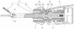
下面参见附图2、3,详细说明根据本申请第一种实施方式的可重复使用的超声手术器械。如图2所示,该可重复使用的超声手术器械3包括套管组件31、刀杆5、基座32及夹持驱动组件71,所述基座32设置在握柄8的远端,所述套管组件31可与基座32及夹持驱动组件71可拆卸地连接。所述套管组件31包括位于其远端的夹钳4、外套管61和内套管62。所述夹钳4的近端设置两个旋转轴41和42,其中旋转轴41与外套管61的远端旋转连接,旋转轴42与内套管62的远端旋转连接。内套管62安装在刀杆5外部,外套管61安装在内套管62外部,且外套管61和内套管62都与刀杆5同轴。通过上述设置,当外套管61固定时,旋转轴41也被固定,沿刀杆5轴线来回拉动内套管62,带动旋转轴42来回运动,从而使得夹钳4绕着旋转轴41转动,实现夹钳4与刀头之间的张开与闭合。Referring to Figures 2 and 3 below, the reusable ultrasonic surgical instrument according to the first embodiment of the present application will be described in detail. As shown in FIG. 2 , the reusable ultrasonic
套管组件31可向着刀杆5轴线的远端方向从基座32及夹持驱动组件71拆卸,也可向着刀杆5轴线的近端方向安装在基座32及夹持驱动组件71上。这样的功能主要是通过第一可拆卸结构33及第二可拆卸结构34实现的,其中,第一可拆卸结构33是外套管61与基座32之间的连接结构,第二可拆卸结构34是内套管62与夹持驱动组件71之间的连接结构。所述基座32相对于握柄8在刀杆5轴线方向的运动被固定,夹持驱动组件71与抓持机构7连接并由抓持机构7驱动沿着刀杆5轴线方向来回运动。因此当外套管61被第一可拆卸结构33连接到基座32上,内套管62被第二可拆卸结构34连接到夹持驱动组件71上之后,夹持驱动组件71可带动内套管62相对于基座32沿刀杆5的轴线方向来回运动,从而带动夹钳4相对于刀杆5的头部张开或者闭合。The
参见图2,根据本申请第一种实施方式的可重复使用的超声手术器械中,第一可拆卸结构33由基座32上的光孔333、设置在外套管61近端的螺纹孔331及螺栓332组成。螺栓332穿过光孔333拧紧在螺纹孔331上,这样外套管61与基座32在刀杆5的轴线方向与周线方向便被约束在一起。本领域技术人员容易想到,也可以光孔333设置外套管61近端,而将螺纹孔331设置在基座32上。Referring to FIG. 2 , in the reusable ultrasonic surgical instrument according to the first embodiment of the present application, the first
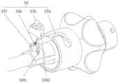
参见附图2、3,第二可拆卸结构34由第二卡位槽342和搭扣结构341组成,其中,第二卡位槽342设置在内套管62近端,搭扣结构341设置在夹持驱动组件71远端。参见图3,详细示出了该实施方式中的第二可拆卸结构34,所述第二卡位槽342由第二滑动槽3421及第二止位槽3422构成,第二滑动槽3421平行于刀杆5的轴线方向并起始于刀杆5的最近端部,第二止位槽3422垂直于刀杆5的轴线方向延伸并与第二滑动槽3421的远端连通;设置在夹持驱动组件71远端的所述搭扣结构341平行于刀杆5的轴线方向,其宽度等于或略小于所述第二滑动槽3421的宽度,并且在垂直于刀杆5的轴线方向上向内具有勾状突起,所述搭扣结构341可滑入第二滑动槽3421进而进入第二止位槽3422,并且所述搭扣结构341可相对第二卡位槽342转动设定的安装角度后搭扣在第二止位槽3422上,从而所述搭扣结构341沿刀杆5轴线方向的运动被第二止位槽3422约束,使得搭扣结构341能带动第二卡位槽342沿刀杆5的轴线方向运动。Referring to FIGS. 2 and 3 , the second
当套管组件31与基座32及夹持驱动组件71连接时,首先将驱动组件71上的搭扣结构341滑入内套管62近端的第二滑动槽3421进而进入第二止位槽3422,接着将套管组件31转动设定的安装角度后使得搭扣结构341搭扣在第二止位槽3422上,从而将内套管62与夹持驱动组件71连接在一起,接着螺栓332穿过基座32上的光孔333拧紧在外套管61上的螺纹孔331中,将外套管61与基座32连接在一起。当套管组件31从基座32及夹持驱动组件71拆卸时,首先将第一可拆卸结构33的螺栓332从螺纹孔331上拧出并从光孔333里退出,然后将套管组件31转动设定的安装角度,使得搭扣结构341从第二止位槽3422转到第二滑动槽3421,最后将套管组件31向着刀杆5轴线的远端方向移出即完成了套管组件31与基座32及夹持驱动组件71的拆卸。When the
下面参见附图4、5,详细说明根据本申请第二种实施方式的可重复使用的超声手术器械。该实施方式中大部分特征与第一种实施方式相同,在此不再重复,并且,图4中的第二可拆卸结构34与图2中的实施例中相同,图4与图2的不同之处仅在于第一可拆卸结构33的构造。参见附图4,外套管61由套管主体611和位于套管主体611近端的卡位座612构成,其中,套管主体611为金属材料制造,卡位座612为金属或者非金属材料制造,二者可用焊接、粘接或者共铸方式结合在一起。第一可拆卸结构33由第一卡位槽334、按钮335、弹性元件336和卡座337组成。所述第一卡位槽334设置在卡位座612上,按钮335、弹性元件336和卡座337设置在基座32上。图5详细示出了第一卡位槽334及按钮335的详细结构,其中第一卡位槽334由整体呈L形的第一滑动槽及与第一滑动槽连接的第一止位槽3343构成,所述第一滑动槽由与刀杆5轴线平行的第一部分3341和与刀杆5轴线垂直的第二部分3342组成,其中第一部分3341的一端起始于基座32的近端侧,另一端与第二部分3342的一个端部相连,第二部分3342的另一端与第一止位槽3343相连,并且第一止位槽3343的最大槽宽大于第一滑动槽最大槽宽。所述按钮335具有一按钮轴线3351,并且所述弹性元件336设置在按钮335下方使得按钮335能沿着按钮轴线3351方向在最高位和最低位之间运动。按钮335由沿着按钮轴线3351方向分布的安装段3354、止位段3353及拆卸段3352相互连接构成,安装段3354垂直于按钮轴线3351方向的横截面的最大宽度大于止位段3353垂直于按钮轴线3351方向的横截面的最大宽度,止位段3353垂直于按钮轴线3351方向的横截面的最大宽度大于拆卸段3352垂直于按钮轴线3351方向的横截面的最大宽度。位于按钮335最下端的安装段3354与基座32上的卡座337及弹性元件336连接。位于安装段3354上方的止位段3353可嵌入卡位座612上的第一止位槽3343,并能被第一止位槽3343约束垂直于按钮轴线3351方向的运动。位于止位段3353上方的拆卸段3352垂直于按钮轴线3351方向的横截面的最大宽度小于第一卡位槽334的最小宽度,所以能在第一卡位槽334内自由滑动。卡座337为基座32上的结构,按钮335的安装段3354及弹性元件336安装在卡座337内。弹性元件336可为圆柱弹簧、波簧或者其它弹性体,其一端压在按钮335的安装段3354的底部,一端压在封闭卡座337底部的孔的圆柱形零件35上。因受弹性元件336的弹力,在自然状态下按钮335处于最高位,此时若按钮335的止位段3353嵌入第一止位槽3343中,可以实现外套管61沿刀杆5轴线和周线方向的固定。当有外力按压按钮335使得按钮335克服弹性元件336的弹力运动到最低位,此时按钮335的拆卸段3352位于第一卡位槽334中,按钮335就可在第一卡位槽334中运动并可依次从第一止位槽3343、第一滑动槽的与刀杆5轴线垂直的第二部分3342及第一滑动槽的与刀杆5轴线平行的第一部分3341滑出,从而外套管61与基座32分离。Referring to Figures 4 and 5 below, the reusable ultrasonic surgical instrument according to the second embodiment of the present application will be described in detail. Most of the features in this embodiment are the same as those in the first embodiment, which will not be repeated here. Moreover, the second
下面参见附图6、7,详细说明根据本申请第三种实施方式的可重复使用的超声手术器械。该实施方式中大部分特征与第二种实施方式相同,在此不再重复,该实施方式与图4、5所示的第二种实施方式的区别仅在于第一可拆卸结构33设置对象不同。参见附图6、7,外套管61由套管主体611和位于套管主体611近端的卡位座612构成,其中,套管主体611为金属材料制造,卡位座612为金属或者非金属材料制造,二者可用焊接、粘接或者共铸方式结合在一起。第一可拆卸结构33由第一卡位槽334、按钮335、弹性元件336和卡座337组成。所述第一卡位槽334设置在基座32上,按钮335、弹性元件336和卡座337设置在卡位座612上。其余结构及安装拆卸方式与图4、5中实施例相同,在此不再重复。Referring to Figures 6 and 7 below, the reusable ultrasonic surgical instrument according to the third embodiment of the present application will be described in detail. Most of the features of this embodiment are the same as those of the second embodiment, which will not be repeated here. The only difference between this embodiment and the second embodiment shown in FIGS. 4 and 5 is that the first
图8是第三种实施例的第一可拆卸结构33的一种变形结构示意图。在该结构中,第一可拆卸结构33由第一卡位槽334、按钮335、弹性元件336和卡座337组成。其中,按钮335与卡座337之间由卡扣结构连接,卡扣3381设置在卡座337上,扣眼3382设置在按钮335上。将弹性元件336装入卡座337内,再将按钮335套入卡座337上,使得卡扣3381扣入扣眼3382,就完成了按钮335与卡座337之间的连接。扣眼3382的高度大于卡扣3381的高度,使得卡扣3381可沿按钮轴线方向在扣眼3382内活动,从而按钮335可在最高位与最低位之间运动。FIG. 8 is a schematic diagram of a modified structure of the first
根据本申请的可重复使用的超声手术器械,解决了市场上主流的超声手术器械使用后不容易清洗,不能重复使用的问题,能显著降低器械的使用成本。并且相对于现有技术中的可重复使用的超声系统,本申请的可重复使用的超声手术器械中可重复使用的部件增多从而进一步降低使用成本,并且拆卸的方便性、整体结构的可靠性、工艺实现的简便性都有提升。总之,本申请相比于现有技术具有结构简单、成本低的优点。The reusable ultrasonic surgical instrument according to the present application solves the problems that the mainstream ultrasonic surgical instruments on the market are not easy to clean after use and cannot be reused, and can significantly reduce the use cost of the instrument. And compared with the reusable ultrasonic system in the prior art, the reusable ultrasonic surgical instrument of the present application has more reusable parts, thereby further reducing the use cost, and the convenience of disassembly, the reliability of the overall structure, The simplicity of process realization has been improved. In conclusion, compared with the prior art, the present application has the advantages of simple structure and low cost.
需要说明的是,附图中的实施方案仅为本申请比较有代表性的实施例,本领域技术人员容易理解,本申请的保护范围不仅仅限定在附图中实施方式所限定的范围内,对附图中实施方式的组合、变形、变化均落在本申请的保护范围内。It should be noted that the embodiments in the accompanying drawings are only representative examples of the present application. Those skilled in the art can easily understand that the protection scope of the present application is not limited only to the scope limited by the embodiments in the accompanying drawings. The combination, deformation and change of the embodiments in the accompanying drawings all fall within the protection scope of the present application.
以上所揭露的仅为本申请几种较佳实施例而已,当然不能以此来限定本申请之权利范围,因此依本申请权利要求所作的等同变化,仍属本申请所涵盖范围。The above disclosures are only a few preferred embodiments of the present application, and of course, the scope of the rights of the present application cannot be limited by this. Therefore, equivalent changes made according to the claims of the present application are still within the scope of the present application.
Claims (17)
Translated fromChinesePriority Applications (5)
| Application Number | Priority Date | Filing Date | Title |
|---|---|---|---|
| CN201710602001.7ACN107280735B (en) | 2017-07-21 | 2017-07-21 | Repeatedly-usable ultrasonic surgical instrument |
| PCT/CN2018/094989WO2019015502A1 (en) | 2017-07-21 | 2018-07-09 | Reusable ultrasonic surgical instrument |
| JP2020502364AJP6892644B2 (en) | 2017-07-21 | 2018-07-09 | Reusable ultrasonic surgical instruments |
| US16/632,599US20210161552A1 (en) | 2017-07-21 | 2018-07-09 | Reusable ultrasonic surgical instrument |
| EP18835786.7AEP3656319A4 (en) | 2017-07-21 | 2018-07-09 | Reusable ultrasonic surgical instrument |
Applications Claiming Priority (1)
| Application Number | Priority Date | Filing Date | Title |
|---|---|---|---|
| CN201710602001.7ACN107280735B (en) | 2017-07-21 | 2017-07-21 | Repeatedly-usable ultrasonic surgical instrument |
Publications (2)
| Publication Number | Publication Date |
|---|---|
| CN107280735A CN107280735A (en) | 2017-10-24 |
| CN107280735Btrue CN107280735B (en) | 2020-08-04 |
Family
ID=60102760
Family Applications (1)
| Application Number | Title | Priority Date | Filing Date |
|---|---|---|---|
| CN201710602001.7AActiveCN107280735B (en) | 2017-07-21 | 2017-07-21 | Repeatedly-usable ultrasonic surgical instrument |
Country Status (5)
| Country | Link |
|---|---|
| US (1) | US20210161552A1 (en) |
| EP (1) | EP3656319A4 (en) |
| JP (1) | JP6892644B2 (en) |
| CN (1) | CN107280735B (en) |
| WO (1) | WO2019015502A1 (en) |
Families Citing this family (20)
| Publication number | Priority date | Publication date | Assignee | Title |
|---|---|---|---|---|
| CN109431578B (en)* | 2017-12-25 | 2024-04-12 | 上海逸思医疗科技股份有限公司 | Ultrasonic surgical instrument with detachable sleeve assembly |
| CN108354652A (en)* | 2018-02-08 | 2018-08-03 | 南昌元合泽众科技有限公司 | A kind of reusable ultrasonic surgical blade |
| CN108261231B (en)* | 2018-03-12 | 2024-04-16 | 杰尼肯(苏州)医疗器械有限公司 | Puncture sleeve device of small-sized laparoscope puncture outfit |
| CN108742888B (en)* | 2018-06-19 | 2022-05-17 | 青岛市口腔医院 | Surgical instrument for department of stomatology |
| CN109009330B (en)* | 2018-08-02 | 2023-09-29 | 嘉善飞阔医疗科技有限公司 | Ultrasonic surgical knife and ultrasonic surgical knife system |
| CN109044491B (en)* | 2018-09-03 | 2020-12-18 | 上海题屏医疗科技有限公司 | Ultrasonic scalpel |
| CN111281455B (en)* | 2018-12-07 | 2025-03-11 | 上海逸思医疗科技股份有限公司 | Reusable stapler with detachable adapter |
| CN109674527B (en)* | 2018-12-25 | 2024-04-12 | 上海逸思医疗科技股份有限公司 | A detachable surgical instrument |
| CN110448357B (en)* | 2019-08-15 | 2024-01-09 | 以诺康医疗科技(苏州)有限公司 | Reusable ultrasonic surgical knife |
| CN112932618A (en)* | 2019-11-26 | 2021-06-11 | 北京安和加利尔科技有限公司 | Cutter bar for ultrasonic scalpel and ultrasonic scalpel |
| CN114343824B (en)* | 2020-10-13 | 2024-12-10 | 上海逸思医疗科技股份有限公司 | Removable medical devices |
| CN113952034B (en)* | 2020-10-20 | 2023-05-23 | 成都博恩思医学机器人有限公司 | Quick-dismantling surgical instrument |
| CN113456176A (en)* | 2020-11-04 | 2021-10-01 | 安速康医疗(苏州)有限公司 | Ultrasonic scalpel handle |
| CN112515738B (en)* | 2020-11-12 | 2023-06-13 | 嘉善飞阔医疗科技有限公司 | Ultrasonic scalpel capable of being stably and repeatedly used |
| CN114533248A (en)* | 2020-11-24 | 2022-05-27 | 上海逸思医疗科技股份有限公司 | Detachable surgical operation instrument |
| CN112472219B (en)* | 2020-11-27 | 2022-07-19 | 常州安康医疗器械有限公司 | Ultrasonic knife with double-horizontal pulse output mode |
| CN112741672A (en)* | 2020-12-30 | 2021-05-04 | 常州柯柏电子科技有限公司 | Novel handheld ultrasonic cutter |
| CN215273148U (en)* | 2021-03-03 | 2021-12-24 | 安速康医疗(苏州)有限公司 | Ultrasound scalpel handle and ultrasound scalpel |
| CN114886550B (en)* | 2022-04-15 | 2023-03-21 | 以诺康医疗科技(苏州)有限公司 | Gun-type electric knife with on-off sliding contact ring structure |
| CN115530929B (en)* | 2022-10-13 | 2024-04-16 | 以诺康医疗科技(苏州)有限公司 | Fine surgical instrument |
Family Cites Families (14)
| Publication number | Priority date | Publication date | Assignee | Title |
|---|---|---|---|---|
| US6214023B1 (en)* | 1999-06-21 | 2001-04-10 | Ethicon Endo-Surgery, Inc. | Ultrasonic surgical instrument with removable clamp arm |
| US20020165577A1 (en)* | 2001-05-04 | 2002-11-07 | Ethicon Endo-Surgery, Inc. | Easily detachable ultrasonic clamping device |
| JP4315716B2 (en)* | 2003-03-20 | 2009-08-19 | オリンパス株式会社 | Ultrasonic treatment device |
| US7749227B2 (en)* | 2003-04-28 | 2010-07-06 | Greatbatch Medical S.A. | Precision assembleable surgical tool handle with limited-play interconnect mechanism |
| US20060079879A1 (en)* | 2004-10-08 | 2006-04-13 | Faller Craig N | Actuation mechanism for use with an ultrasonic surgical instrument |
| EP1905362A1 (en)* | 2006-09-29 | 2008-04-02 | Precimed S.A. | Precision assembleable surgical tool handle with limited-play interconnect mechanism |
| US20100331742A1 (en)* | 2009-06-26 | 2010-12-30 | Shinya Masuda | Surgical operating apparatus |
| US10085792B2 (en)* | 2010-11-05 | 2018-10-02 | Ethicon Llc | Surgical instrument with motorized attachment feature |
| CA2816877A1 (en)* | 2010-11-05 | 2012-05-10 | Ethicon Endo-Surgery, Inc. | Surgical instrument with modular clamp pad |
| CN202908793U (en) | 2012-11-09 | 2013-05-01 | 北京安和加利尔科技有限公司 | Ultrasonic scalpel with changeable scalpel bar |
| US9724120B2 (en) | 2013-12-17 | 2017-08-08 | Ethicon Endo-Surgery, Llc | Clamp arm features for ultrasonic surgical instrument |
| CN203988246U (en)* | 2014-08-14 | 2014-12-10 | 武汉半边天医疗技术发展有限公司 | A kind of removable ultrasound knife pipe fast junction apparatus |
| US11464534B2 (en)* | 2015-12-08 | 2022-10-11 | Reach Surgical, Inc. | Ultrasonic surgical instrument |
| CN106901805A (en)* | 2015-12-22 | 2017-06-30 | 无锡祥生医学影像有限责任公司 | The power limit structure of ultrasound knife transducer module |
- 2017
- 2017-07-21CNCN201710602001.7Apatent/CN107280735B/enactiveActive
- 2018
- 2018-07-09WOPCT/CN2018/094989patent/WO2019015502A1/ennot_activeCeased
- 2018-07-09USUS16/632,599patent/US20210161552A1/ennot_activeAbandoned
- 2018-07-09EPEP18835786.7Apatent/EP3656319A4/ennot_activeWithdrawn
- 2018-07-09JPJP2020502364Apatent/JP6892644B2/ennot_activeExpired - Fee Related
Also Published As
| Publication number | Publication date |
|---|---|
| JP2020526349A (en) | 2020-08-31 |
| WO2019015502A1 (en) | 2019-01-24 |
| EP3656319A4 (en) | 2021-03-24 |
| US20210161552A1 (en) | 2021-06-03 |
| CN107280735A (en) | 2017-10-24 |
| JP6892644B2 (en) | 2021-06-23 |
| EP3656319A1 (en) | 2020-05-27 |
Similar Documents
| Publication | Publication Date | Title |
|---|---|---|
| CN107280735B (en) | Repeatedly-usable ultrasonic surgical instrument | |
| CN211066895U (en) | Ultrasonic surgical instrument with detachable sleeve assembly | |
| JP4493893B2 (en) | Multifunctional curved blade for use with ultrasonic surgical instruments | |
| JP5855584B2 (en) | Ultrasonic surgical instrument with a partially rotating blade and fixed pad arrangement | |
| US6340352B1 (en) | Ultrasound treatment system | |
| US5322055A (en) | Clamp coagulator/cutting system for ultrasonic surgical instruments | |
| JP4675947B2 (en) | Blade with functional balancing asymmetric portion for use with an ultrasonic surgical instrument | |
| JP5795337B2 (en) | Rotatable cutting configuration for ultrasonic surgical instruments | |
| JP5813668B2 (en) | Sealing arrangement for ultrasonically driven surgical instruments | |
| EP2644144A1 (en) | Bipolar treatment device | |
| EP3871618B1 (en) | Ultrasonic surgical instrument with integral torque wrench and transverse engagement | |
| WO2016197348A1 (en) | Ultrasonic surgery device and end effector | |
| CN116999122A (en) | A simple replacement device for ultrasonic scalpel and ultrasonic scalpel | |
| CN218105990U (en) | Simple ultrasonic knife replacing device | |
| CN210697757U (en) | Detachable ultrasonic knife head | |
| CN113616281B (en) | Ultrasonic knife | |
| BR112019011411B1 (en) | ULTRASONIC SURGICAL INSTRUMENT WITH INTEGRAL SLIDING LOCK BETWEEN INSTRUMENT BODY AND ULTRASONIC TRANSDUCER |
Legal Events
| Date | Code | Title | Description |
|---|---|---|---|
| PB01 | Publication | ||
| PB01 | Publication | ||
| SE01 | Entry into force of request for substantive examination | ||
| SE01 | Entry into force of request for substantive examination | ||
| TA01 | Transfer of patent application right | Effective date of registration:20190318 Address after:215002 Building 16, No. 8 Jinfeng Road, Suzhou High-tech Zone, Jiangsu Province Applicant after:Yat thinking (Suzhou) Medical Technology Co., Ltd. Address before:201203 Cailun Road 169, Shanghai Pudong New Area Free Trade Pilot Area Applicant before:Shanghai Yisi Medical Technology Co., Ltd. Applicant before:Yat thinking (Suzhou) Medical Technology Co., Ltd. | |
| TA01 | Transfer of patent application right | ||
| TA01 | Transfer of patent application right | Effective date of registration:20190618 Address after:Block A, 199 Lane 1, Tianxiong Road, Pudong New Area, Shanghai, 201318 Applicant after:Shanghai Yisi Medical Technology Co., Ltd. Address before:215002 Building 16, No. 8 Jinfeng Road, Suzhou High-tech Zone, Jiangsu Province Applicant before:Yat thinking (Suzhou) Medical Technology Co., Ltd. | |
| TA01 | Transfer of patent application right | ||
| GR01 | Patent grant | ||
| GR01 | Patent grant | ||
| CP01 | Change in the name or title of a patent holder | Address after:Block A, 199 Lane 1, Tianxiong Road, Pudong New Area, Shanghai, 201318 Patentee after:Shanghai Yisi Medical Technology Co.,Ltd. Address before:Block A, 199 Lane 1, Tianxiong Road, Pudong New Area, Shanghai, 201318 Patentee before:SHANGHAI YISI MEDICAL TECHNOLOGY Co.,Ltd. | |
| CP01 | Change in the name or title of a patent holder |