CN107256681B - Lamp box cloth and lamp box - Google Patents
Lamp box cloth and lamp boxDownload PDFInfo
- Publication number
- CN107256681B CN107256681BCN201710625424.0ACN201710625424ACN107256681BCN 107256681 BCN107256681 BCN 107256681BCN 201710625424 ACN201710625424 ACN 201710625424ACN 107256681 BCN107256681 BCN 107256681B
- Authority
- CN
- China
- Prior art keywords
- light
- layer
- cloth
- light box
- light source
- Prior art date
- Legal status (The legal status is an assumption and is not a legal conclusion. Google has not performed a legal analysis and makes no representation as to the accuracy of the status listed.)
- Expired - Fee Related
Links
Images


Classifications
- G—PHYSICS
- G09—EDUCATION; CRYPTOGRAPHY; DISPLAY; ADVERTISING; SEALS
- G09F—DISPLAYING; ADVERTISING; SIGNS; LABELS OR NAME-PLATES; SEALS
- G09F13/00—Illuminated signs; Luminous advertising
- G09F13/04—Signs, boards or panels, illuminated from behind the insignia
- B—PERFORMING OPERATIONS; TRANSPORTING
- B32—LAYERED PRODUCTS
- B32B—LAYERED PRODUCTS, i.e. PRODUCTS BUILT-UP OF STRATA OF FLAT OR NON-FLAT, e.g. CELLULAR OR HONEYCOMB, FORM
- B32B27/00—Layered products comprising a layer of synthetic resin
- B32B27/06—Layered products comprising a layer of synthetic resin as the main or only constituent of a layer, which is next to another layer of the same or of a different material
- B32B27/08—Layered products comprising a layer of synthetic resin as the main or only constituent of a layer, which is next to another layer of the same or of a different material of synthetic resin
- B—PERFORMING OPERATIONS; TRANSPORTING
- B32—LAYERED PRODUCTS
- B32B—LAYERED PRODUCTS, i.e. PRODUCTS BUILT-UP OF STRATA OF FLAT OR NON-FLAT, e.g. CELLULAR OR HONEYCOMB, FORM
- B32B27/00—Layered products comprising a layer of synthetic resin
- B32B27/12—Layered products comprising a layer of synthetic resin next to a fibrous or filamentary layer
- B—PERFORMING OPERATIONS; TRANSPORTING
- B32—LAYERED PRODUCTS
- B32B—LAYERED PRODUCTS, i.e. PRODUCTS BUILT-UP OF STRATA OF FLAT OR NON-FLAT, e.g. CELLULAR OR HONEYCOMB, FORM
- B32B27/00—Layered products comprising a layer of synthetic resin
- B32B27/18—Layered products comprising a layer of synthetic resin characterised by the use of special additives
- B32B27/20—Layered products comprising a layer of synthetic resin characterised by the use of special additives using fillers, pigments, thixotroping agents
- B—PERFORMING OPERATIONS; TRANSPORTING
- B32—LAYERED PRODUCTS
- B32B—LAYERED PRODUCTS, i.e. PRODUCTS BUILT-UP OF STRATA OF FLAT OR NON-FLAT, e.g. CELLULAR OR HONEYCOMB, FORM
- B32B27/00—Layered products comprising a layer of synthetic resin
- B32B27/30—Layered products comprising a layer of synthetic resin comprising vinyl (co)polymers; comprising acrylic (co)polymers
- B32B27/302—Layered products comprising a layer of synthetic resin comprising vinyl (co)polymers; comprising acrylic (co)polymers comprising aromatic vinyl (co)polymers, e.g. styrenic (co)polymers
- B—PERFORMING OPERATIONS; TRANSPORTING
- B32—LAYERED PRODUCTS
- B32B—LAYERED PRODUCTS, i.e. PRODUCTS BUILT-UP OF STRATA OF FLAT OR NON-FLAT, e.g. CELLULAR OR HONEYCOMB, FORM
- B32B27/00—Layered products comprising a layer of synthetic resin
- B32B27/30—Layered products comprising a layer of synthetic resin comprising vinyl (co)polymers; comprising acrylic (co)polymers
- B32B27/304—Layered products comprising a layer of synthetic resin comprising vinyl (co)polymers; comprising acrylic (co)polymers comprising vinyl halide (co)polymers, e.g. PVC, PVDC, PVF, PVDF
- B—PERFORMING OPERATIONS; TRANSPORTING
- B32—LAYERED PRODUCTS
- B32B—LAYERED PRODUCTS, i.e. PRODUCTS BUILT-UP OF STRATA OF FLAT OR NON-FLAT, e.g. CELLULAR OR HONEYCOMB, FORM
- B32B27/00—Layered products comprising a layer of synthetic resin
- B32B27/30—Layered products comprising a layer of synthetic resin comprising vinyl (co)polymers; comprising acrylic (co)polymers
- B32B27/308—Layered products comprising a layer of synthetic resin comprising vinyl (co)polymers; comprising acrylic (co)polymers comprising acrylic (co)polymers
- B—PERFORMING OPERATIONS; TRANSPORTING
- B32—LAYERED PRODUCTS
- B32B—LAYERED PRODUCTS, i.e. PRODUCTS BUILT-UP OF STRATA OF FLAT OR NON-FLAT, e.g. CELLULAR OR HONEYCOMB, FORM
- B32B27/00—Layered products comprising a layer of synthetic resin
- B32B27/32—Layered products comprising a layer of synthetic resin comprising polyolefins
- B—PERFORMING OPERATIONS; TRANSPORTING
- B32—LAYERED PRODUCTS
- B32B—LAYERED PRODUCTS, i.e. PRODUCTS BUILT-UP OF STRATA OF FLAT OR NON-FLAT, e.g. CELLULAR OR HONEYCOMB, FORM
- B32B27/00—Layered products comprising a layer of synthetic resin
- B32B27/34—Layered products comprising a layer of synthetic resin comprising polyamides
- B—PERFORMING OPERATIONS; TRANSPORTING
- B32—LAYERED PRODUCTS
- B32B—LAYERED PRODUCTS, i.e. PRODUCTS BUILT-UP OF STRATA OF FLAT OR NON-FLAT, e.g. CELLULAR OR HONEYCOMB, FORM
- B32B27/00—Layered products comprising a layer of synthetic resin
- B32B27/36—Layered products comprising a layer of synthetic resin comprising polyesters
- B—PERFORMING OPERATIONS; TRANSPORTING
- B32—LAYERED PRODUCTS
- B32B—LAYERED PRODUCTS, i.e. PRODUCTS BUILT-UP OF STRATA OF FLAT OR NON-FLAT, e.g. CELLULAR OR HONEYCOMB, FORM
- B32B27/00—Layered products comprising a layer of synthetic resin
- B32B27/40—Layered products comprising a layer of synthetic resin comprising polyurethanes
- B—PERFORMING OPERATIONS; TRANSPORTING
- B32—LAYERED PRODUCTS
- B32B—LAYERED PRODUCTS, i.e. PRODUCTS BUILT-UP OF STRATA OF FLAT OR NON-FLAT, e.g. CELLULAR OR HONEYCOMB, FORM
- B32B33/00—Layered products characterised by particular properties or particular surface features, e.g. particular surface coatings; Layered products designed for particular purposes not covered by another single class
- B—PERFORMING OPERATIONS; TRANSPORTING
- B32—LAYERED PRODUCTS
- B32B—LAYERED PRODUCTS, i.e. PRODUCTS BUILT-UP OF STRATA OF FLAT OR NON-FLAT, e.g. CELLULAR OR HONEYCOMB, FORM
- B32B5/00—Layered products characterised by the non- homogeneity or physical structure, i.e. comprising a fibrous, filamentary, particulate or foam layer; Layered products characterised by having a layer differing constitutionally or physically in different parts
- B32B5/02—Layered products characterised by the non- homogeneity or physical structure, i.e. comprising a fibrous, filamentary, particulate or foam layer; Layered products characterised by having a layer differing constitutionally or physically in different parts characterised by structural features of a fibrous or filamentary layer
- B—PERFORMING OPERATIONS; TRANSPORTING
- B32—LAYERED PRODUCTS
- B32B—LAYERED PRODUCTS, i.e. PRODUCTS BUILT-UP OF STRATA OF FLAT OR NON-FLAT, e.g. CELLULAR OR HONEYCOMB, FORM
- B32B7/00—Layered products characterised by the relation between layers; Layered products characterised by the relative orientation of features between layers, or by the relative values of a measurable parameter between layers, i.e. products comprising layers having different physical, chemical or physicochemical properties; Layered products characterised by the interconnection of layers
- B32B7/04—Interconnection of layers
- B32B7/12—Interconnection of layers using interposed adhesives or interposed materials with bonding properties
- G—PHYSICS
- G09—EDUCATION; CRYPTOGRAPHY; DISPLAY; ADVERTISING; SEALS
- G09F—DISPLAYING; ADVERTISING; SIGNS; LABELS OR NAME-PLATES; SEALS
- G09F13/00—Illuminated signs; Luminous advertising
- G09F13/16—Signs formed of or incorporating reflecting elements or surfaces, e.g. warning signs having triangular or other geometrical shape
- B—PERFORMING OPERATIONS; TRANSPORTING
- B32—LAYERED PRODUCTS
- B32B—LAYERED PRODUCTS, i.e. PRODUCTS BUILT-UP OF STRATA OF FLAT OR NON-FLAT, e.g. CELLULAR OR HONEYCOMB, FORM
- B32B2255/00—Coating on the layer surface
- B32B2255/10—Coating on the layer surface on synthetic resin layer or on natural or synthetic rubber layer
- B—PERFORMING OPERATIONS; TRANSPORTING
- B32—LAYERED PRODUCTS
- B32B—LAYERED PRODUCTS, i.e. PRODUCTS BUILT-UP OF STRATA OF FLAT OR NON-FLAT, e.g. CELLULAR OR HONEYCOMB, FORM
- B32B2255/00—Coating on the layer surface
- B32B2255/20—Inorganic coating
- B32B2255/205—Metallic coating
- B—PERFORMING OPERATIONS; TRANSPORTING
- B32—LAYERED PRODUCTS
- B32B—LAYERED PRODUCTS, i.e. PRODUCTS BUILT-UP OF STRATA OF FLAT OR NON-FLAT, e.g. CELLULAR OR HONEYCOMB, FORM
- B32B2307/00—Properties of the layers or laminate
- B32B2307/40—Properties of the layers or laminate having particular optical properties
- B32B2307/412—Transparent
- B—PERFORMING OPERATIONS; TRANSPORTING
- B32—LAYERED PRODUCTS
- B32B—LAYERED PRODUCTS, i.e. PRODUCTS BUILT-UP OF STRATA OF FLAT OR NON-FLAT, e.g. CELLULAR OR HONEYCOMB, FORM
- B32B2307/00—Properties of the layers or laminate
- B32B2307/40—Properties of the layers or laminate having particular optical properties
- B32B2307/416—Reflective
- B—PERFORMING OPERATIONS; TRANSPORTING
- B32—LAYERED PRODUCTS
- B32B—LAYERED PRODUCTS, i.e. PRODUCTS BUILT-UP OF STRATA OF FLAT OR NON-FLAT, e.g. CELLULAR OR HONEYCOMB, FORM
- B32B2307/00—Properties of the layers or laminate
- B32B2307/70—Other properties
- B32B2307/714—Inert, i.e. inert to chemical degradation, corrosion
- B—PERFORMING OPERATIONS; TRANSPORTING
- B32—LAYERED PRODUCTS
- B32B—LAYERED PRODUCTS, i.e. PRODUCTS BUILT-UP OF STRATA OF FLAT OR NON-FLAT, e.g. CELLULAR OR HONEYCOMB, FORM
- B32B2323/00—Polyalkenes
- B32B2323/04—Polyethylene
- B—PERFORMING OPERATIONS; TRANSPORTING
- B32—LAYERED PRODUCTS
- B32B—LAYERED PRODUCTS, i.e. PRODUCTS BUILT-UP OF STRATA OF FLAT OR NON-FLAT, e.g. CELLULAR OR HONEYCOMB, FORM
- B32B2323/00—Polyalkenes
- B32B2323/10—Polypropylene
- B—PERFORMING OPERATIONS; TRANSPORTING
- B32—LAYERED PRODUCTS
- B32B—LAYERED PRODUCTS, i.e. PRODUCTS BUILT-UP OF STRATA OF FLAT OR NON-FLAT, e.g. CELLULAR OR HONEYCOMB, FORM
- B32B2325/00—Polymers of vinyl-aromatic compounds, e.g. polystyrene
- B—PERFORMING OPERATIONS; TRANSPORTING
- B32—LAYERED PRODUCTS
- B32B—LAYERED PRODUCTS, i.e. PRODUCTS BUILT-UP OF STRATA OF FLAT OR NON-FLAT, e.g. CELLULAR OR HONEYCOMB, FORM
- B32B2327/00—Polyvinylhalogenides
- B32B2327/06—PVC, i.e. polyvinylchloride
- B—PERFORMING OPERATIONS; TRANSPORTING
- B32—LAYERED PRODUCTS
- B32B—LAYERED PRODUCTS, i.e. PRODUCTS BUILT-UP OF STRATA OF FLAT OR NON-FLAT, e.g. CELLULAR OR HONEYCOMB, FORM
- B32B2367/00—Polyesters, e.g. PET, i.e. polyethylene terephthalate
- B—PERFORMING OPERATIONS; TRANSPORTING
- B32—LAYERED PRODUCTS
- B32B—LAYERED PRODUCTS, i.e. PRODUCTS BUILT-UP OF STRATA OF FLAT OR NON-FLAT, e.g. CELLULAR OR HONEYCOMB, FORM
- B32B2375/00—Polyureas; Polyurethanes
- B—PERFORMING OPERATIONS; TRANSPORTING
- B32—LAYERED PRODUCTS
- B32B—LAYERED PRODUCTS, i.e. PRODUCTS BUILT-UP OF STRATA OF FLAT OR NON-FLAT, e.g. CELLULAR OR HONEYCOMB, FORM
- B32B2377/00—Polyamides
- B—PERFORMING OPERATIONS; TRANSPORTING
- B32—LAYERED PRODUCTS
- B32B—LAYERED PRODUCTS, i.e. PRODUCTS BUILT-UP OF STRATA OF FLAT OR NON-FLAT, e.g. CELLULAR OR HONEYCOMB, FORM
- B32B2590/00—Signboards, advertising panels, road signs
- Y—GENERAL TAGGING OF NEW TECHNOLOGICAL DEVELOPMENTS; GENERAL TAGGING OF CROSS-SECTIONAL TECHNOLOGIES SPANNING OVER SEVERAL SECTIONS OF THE IPC; TECHNICAL SUBJECTS COVERED BY FORMER USPC CROSS-REFERENCE ART COLLECTIONS [XRACs] AND DIGESTS
- Y02—TECHNOLOGIES OR APPLICATIONS FOR MITIGATION OR ADAPTATION AGAINST CLIMATE CHANGE
- Y02B—CLIMATE CHANGE MITIGATION TECHNOLOGIES RELATED TO BUILDINGS, e.g. HOUSING, HOUSE APPLIANCES OR RELATED END-USER APPLICATIONS
- Y02B20/00—Energy efficient lighting technologies, e.g. halogen lamps or gas discharge lamps
- Y02B20/40—Control techniques providing energy savings, e.g. smart controller or presence detection
Landscapes
- Physics & Mathematics (AREA)
- General Physics & Mathematics (AREA)
- Engineering & Computer Science (AREA)
- Theoretical Computer Science (AREA)
- Geometry (AREA)
- Non-Portable Lighting Devices Or Systems Thereof (AREA)
Abstract
Description
Translated fromChinese技术领域technical field
本发明涉及灯箱技术领域,特别涉及一种灯箱布及灯箱。The invention relates to the technical field of light boxes, in particular to a light box cloth and a light box.
背景技术Background technique
灯箱布由于具有柔韧性好、透光均匀、寿命长、便于分割安装等特性,被广泛用于户外广告灯箱的制作。Light box cloth is widely used in the production of outdoor advertising light boxes because of its good flexibility, uniform light transmission, long life, and easy division and installation.
当前,户外广告灯箱可以显示商家logo(徽标,企业的文字名称、图标或两者相结合的一种标识)信息,以提高商家的辨识度。然而,现有的灯箱颜色单一,在灯箱的各个观察角度都只能观察到同一种设定的颜色,灯箱缺乏颜色多样性。At present, outdoor advertising light boxes can display business logo (logo, company text name, icon or a combination of the two) information to improve the recognition of the business. However, the existing light box has a single color, and only the same set color can be observed at each viewing angle of the light box, and the light box lacks color diversity.
发明内容Contents of the invention
本发明实施例提供一种灯箱布及灯箱,可以提高灯箱的颜色多样性。An embodiment of the present invention provides a light box cloth and a light box, which can increase the color diversity of the light box.
本发明实施例提供一种灯箱布,包括反射层、基材层以及布料层,所述反射层、基材层以及布料层依次层叠设置,所述基材层朝向所述布料层的一侧设置有多个凹槽,所述凹槽中设置有增光膜,所述反射层的材质包括金属。An embodiment of the present invention provides a light box cloth, including a reflective layer, a base layer and a cloth layer, the reflective layer, the base layer and the cloth layer are stacked in sequence, and the base layer is disposed toward the side of the cloth layer There are a plurality of grooves, and a light-enhancing film is arranged in the grooves, and the material of the reflection layer includes metal.
本发明实施例还提供一种灯箱,包括框架和灯箱布,该灯箱布安装在该框架上,该灯箱布为上述任一种灯箱布。The embodiment of the present invention also provides a light box, including a frame and a light box cloth, the light box cloth is installed on the frame, and the light box cloth is any one of the above light box cloth.
本发明实施例提供的灯箱布,由于灯箱布中设置有反射层,因此灯箱布可以反射外部光线,从而灯箱布表面能够呈现金属光泽,从灯箱布外部的不同角度观察时,灯箱布能够呈现出渐变的色彩效果,并且在内部光源发光时,可以通过基材层上设置的凹槽中的增光膜对光线进行亮度提高,从而能够提高灯箱的颜色多样性。The light box cloth provided by the embodiment of the present invention, since the light box cloth is provided with a reflective layer, the light box cloth can reflect external light, so that the surface of the light box cloth can present a metallic luster, and when viewed from different angles outside the light box cloth, the light box cloth can show Gradient color effect, and when the internal light source is emitting light, the brightness of the light can be increased through the enhancement film in the groove provided on the base material layer, so that the color diversity of the light box can be improved.
附图说明Description of drawings
为了更清楚地说明本发明实施例中的技术方案,下面将对实施例描述中所需要使用的附图作简单地介绍。显而易见地,下面描述中的附图仅仅是本发明的一些实施例,对于本领域技术人员来讲,在不付出创造性劳动的前提下,还可以根据这些附图获得其他的附图。In order to illustrate the technical solutions in the embodiments of the present invention more clearly, the following will briefly introduce the drawings that need to be used in the description of the embodiments. Obviously, the drawings in the following description are only some embodiments of the present invention, and those skilled in the art can also obtain other drawings according to these drawings without creative work.
图1是本发明实施例提供的灯箱的第一种结构示意图。Fig. 1 is a schematic diagram of the first structure of the light box provided by the embodiment of the present invention.
图2是本发明实施例提供的灯箱的第二种结构示意图。Fig. 2 is a second structural schematic view of the light box provided by the embodiment of the present invention.
图3是本发明实施例提供的灯箱的第三种结构示意图。Fig. 3 is a schematic diagram of the third structure of the light box provided by the embodiment of the present invention.
图4是本发明实施例提供的灯箱的第四种结构示意图。Fig. 4 is a schematic diagram of the fourth structure of the light box provided by the embodiment of the present invention.
图5是本发明实施例提供的灯箱的第五种结构示意图。Fig. 5 is a schematic diagram of a fifth structure of the light box provided by the embodiment of the present invention.
图6是本发明实施例提供的灯箱的第六种结构示意图。Fig. 6 is a schematic diagram of the sixth structure of the light box provided by the embodiment of the present invention.
图7是本发明实施例提供的灯箱布的第一种剖视图。Fig. 7 is a first cross-sectional view of the light box cloth provided by the embodiment of the present invention.
图8是本发明实施例提供的灯箱布的第二种剖视图。Fig. 8 is a second cross-sectional view of the light box cloth provided by the embodiment of the present invention.
图9是本发明实施例提供的灯箱布的第三种剖视图。Fig. 9 is a third cross-sectional view of the light box cloth provided by the embodiment of the present invention.
图10是本发明实施例提供的灯箱布中的基材层的第一种结构示意图。Fig. 10 is a schematic diagram of the first structure of the base material layer in the light box cloth provided by the embodiment of the present invention.
图11是本发明实施例提供的灯箱布中的基材层的第二种结构示意图。Fig. 11 is a schematic diagram of the second structure of the base material layer in the light box cloth provided by the embodiment of the present invention.
图12是本发明实施例提供的灯箱布中的基材层的第三种结构示意图。Fig. 12 is a schematic diagram of the third structure of the base material layer in the light box cloth provided by the embodiment of the present invention.
图13是本发明实施例提供的灯箱布中的基材层的剖视图。Fig. 13 is a cross-sectional view of the base material layer in the light box cloth provided by the embodiment of the present invention.
图14是本发明实施例提供的灯箱布中的基材层的凹槽的第一种结构示意图。Fig. 14 is a schematic diagram of the first structure of the groove of the base material layer in the light box cloth provided by the embodiment of the present invention.
图15是本发明实施例提供的灯箱布中的基材层的凹槽的第二种结构示意图。Fig. 15 is a schematic diagram of the second structure of the groove of the substrate layer in the light box cloth provided by the embodiment of the present invention.
图16是本发明实施例提供的灯箱布中的基材层的凹槽的第三种结构示意图。Fig. 16 is a schematic diagram of the third structure of the groove of the substrate layer in the light box cloth provided by the embodiment of the present invention.
图17是本发明实施例提供的灯箱布中的基材层的凹槽的第四种结构示意图。Fig. 17 is a schematic diagram of the fourth structure of the groove of the base material layer in the light box cloth provided by the embodiment of the present invention.
具体实施方式Detailed ways
下面将结合本发明实施例中的附图,对本发明实施例中的技术方案进行清楚、完整地描述。显然,所描述的实施例仅仅是本发明一部分实施例,而不是全部的实施例。基于本发明中的实施例,本领域技术人员在没有作出创造性劳动前提下所获得的所有其他实施例,都属于本发明保护的范围。The following will clearly and completely describe the technical solutions in the embodiments of the present invention with reference to the drawings in the embodiments of the present invention. Apparently, the described embodiments are only some of the embodiments of the present invention, but not all of them. Based on the embodiments of the present invention, all other embodiments obtained by those skilled in the art without creative efforts fall within the protection scope of the present invention.
在本发明的描述中,需要理解的是,术语“中心”、“纵向”、“横向”、“长度”、“宽度”、“厚度”、“上”、“下”、“前”、“后”、“左”、“右”、“竖直”、“水平”、“顶”、“底”、“内”、“外”、“顺时针”、“逆时针”等指示的方位或位置关系为基于附图所示的方位或位置关系,仅是为了便于描述本发明和简化描述,而不是指示或暗示所指的装置或元件必须具有特定的方位、以特定的方位构造和操作,因此不能理解为对本发明的限制。此外,术语“第一”、“第二”仅用于描述目的,而不能理解为指示或暗示相对重要性或者隐含指明所指示的技术特征的数量。由此,限定有“第一”、“第二”的特征可以明示或者隐含地包括一个或者更多个所述特征。在本发明的描述中,“多个”的含义是两个或两个以上,除非另有明确具体的限定。In describing the present invention, it should be understood that the terms "center", "longitudinal", "transverse", "length", "width", "thickness", "upper", "lower", "front", " Orientation indicated by rear, left, right, vertical, horizontal, top, bottom, inside, outside, clockwise, counterclockwise, etc. The positional relationship is based on the orientation or positional relationship shown in the drawings, which is only for the convenience of describing the present invention and simplifying the description, rather than indicating or implying that the referred device or element must have a specific orientation, be constructed and operated in a specific orientation, Therefore, it should not be construed as limiting the invention. In addition, the terms "first" and "second" are used for descriptive purposes only, and cannot be interpreted as indicating or implying relative importance or implicitly specifying the quantity of indicated technical features. Thus, a feature defined as "first" or "second" may explicitly or implicitly include one or more of said features. In the description of the present invention, "plurality" means two or more, unless otherwise specifically defined.
在本发明的描述中,需要说明的是,除非另有明确的规定和限定,术语“安装”、“相连”、“连接”应做广义理解,例如,可以是固定连接,也可以是可拆卸连接,或一体地连接;可以是机械连接,也可以是电连接或可以相互通讯;可以是直接相连,也可以通过中间媒介间接相连,可以是两个元件内部的连通或两个元件的相互作用关系。对于本领域的普通技术人员而言,可以根据具体情况理解上述术语在本发明中的具体含义。In the description of the present invention, it should be noted that unless otherwise specified and limited, the terms "installation", "connection" and "connection" should be understood in a broad sense, for example, it can be a fixed connection or a detachable connection. Connected, or integrally connected; it can be mechanically connected, or electrically connected, or can communicate with each other; it can be directly connected, or indirectly connected through an intermediary, and it can be the internal communication of two components or the interaction of two components relation. Those of ordinary skill in the art can understand the specific meanings of the above terms in the present invention according to specific situations.
在本发明中,除非另有明确的规定和限定,第一特征在第二特征之“上”或之“下”可以包括第一和第二特征直接接触,也可以包括第一和第二特征不是直接接触而是通过它们之间的另外的特征接触。而且,第一特征在第二特征“之上”、“上方”和“上面”包括第一特征在第二特征正上方和斜上方,或仅仅表示第一特征水平高度高于第二特征。第一特征在第二特征“之下”、“下方”和“下面”包括第一特征在第二特征正下方和斜下方,或仅仅表示第一特征水平高度小于第二特征。In the present invention, unless otherwise clearly specified and limited, a first feature being "on" or "under" a second feature may include direct contact between the first and second features, and may also include the first and second features Not in direct contact but through another characteristic contact between them. Moreover, "above", "above" and "above" the first feature on the second feature include that the first feature is directly above and obliquely above the second feature, or simply means that the first feature is horizontally higher than the second feature. "Below", "beneath" and "under" the first feature to the second feature include that the first feature is directly below and obliquely below the second feature, or simply means that the first feature has a lower level than the second feature.
下文的公开提供了许多不同的实施方式或例子用来实现本发明的不同结构。为了简化本发明的公开,下文中对特定例子的部件和设置进行描述。当然,它们仅仅为示例,并且目的不在于限制本发明。此外,本发明可以在不同例子中重复参考数字和/或参考字母,这种重复是为了简化和清楚的目的,其本身不指示所讨论各种实施方式和/或设置之间的关系。此外,本发明提供了的各种特定的工艺和材料的例子,但是本领域普通技术人员可以意识到其他工艺的应用和/或其他材料的使用。The following disclosure provides many different embodiments or examples for implementing different structures of the present invention. To simplify the disclosure of the present invention, components and arrangements of specific examples are described below. Of course, they are only examples and are not intended to limit the invention. Furthermore, the present disclosure may repeat reference numerals and/or reference letters in different instances, such repetition is for simplicity and clarity and does not in itself indicate a relationship between the various embodiments and/or arrangements discussed. In addition, various specific process and material examples are provided herein, but one of ordinary skill in the art may recognize the use of other processes and/or the use of other materials.
本发明实施例提供一种灯箱。该灯箱可以应用于户外大型广告牌,或者应用于商家门店,以向用户传递商家的信息。An embodiment of the present invention provides a light box. The light box can be applied to large outdoor billboards, or to storefronts of merchants to deliver merchant information to users.
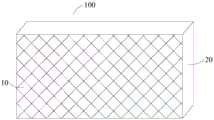
如图1所示,灯箱100包括灯箱布10和框架20。其中,框架20可以是由金属、塑料或木质板材等材料所制成的。框架20的外部轮廓可以为长方体。在一些实施例中,框架20的外部轮廓还可以是球体等其他形状。As shown in FIG. 1 , the
灯箱布10安装在框架20上。其中,灯箱布10可以覆盖框架20的一部分表面。例如,框架20为长方体框架时,灯箱布10可以覆盖框架20的一个面。The
在一些实施例中,框架20覆盖有灯箱布10的表面还可以设置玻璃层。该玻璃层可以将灯箱布10压紧在框架20的表面,同时对灯箱布10提供保护作用。In some embodiments, the surface of the
在一些实施例中,如图2所示,灯箱100还包括光源30。光源30安装在框架20内部。光源30可以为点光源、面光源等种类的光源。灯箱布10具有透光性。当处于夜晚或者白天外部环境光线较暗时,光源30开启,以透过灯箱布10向外部发射可见光,从而提高灯箱100的可见度。In some embodiments, as shown in FIG. 2 , the
在一些实施例中,光源30可以是由多个发光二极管形成的面光源。光源30包括多个彼此间隔设置的发光二极管31。多个发光二极管形成的面光源30可以与灯箱布10平行设置。光源30的发光面朝向灯箱布10。In some embodiments, the
在一些实施例中,如图3所示,光源30可以是由多个发光二极管形成的面光源。光源30包括多个彼此间隔设置的发光二极管31。多个发光二极管形成的面光源30可以设置在灯箱100的侧壁上。也即,面光源30与灯箱布10互相垂直。光源30中的发光二极管31可以呈一定角度设置。例如,发光二极管31与光源30所处的平面之间形成30度角。光源30发射的光线朝向灯箱布10。当处于夜晚或者白天外部环境光线较暗时,光源30开启,以透过灯箱布10向外部发射可见光,从而提高灯箱100的可见度。In some embodiments, as shown in FIG. 3 , the
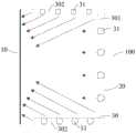
在一些实施例中,如图4所示,光源30可以是由多个发光二极管形成的面光源。光源30包括多个彼此间隔设置的发光二极管31。其中,光源30可以包括与灯箱布10平行设置的第一部分301以及与灯箱布10垂直设置的第二部分302。第一部分301的发光面朝向灯箱布10。第二部分302中的发光二极管31可以呈一定角度设置。例如,发光二极管31与第二部分302所处的平面之间形成30度角。从而第二部分302发射的光线也朝向灯箱布10。In some embodiments, as shown in FIG. 4 , the
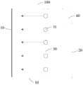
在一些实施例中,如图5所示,灯箱100还包括控制电路40。控制电路40安装在框架20内部。其中,控制电路40与光源30连接。控制电路40用于控制光源30开启和关闭。例如,用户可以设定光源30开启和关闭的时刻。当时间到达预设的开启时刻时,控制电路40控制光源30开启。从而光源30透过灯箱布10向外部发射可见光,从而提高灯箱100的可见度。当时间到达预设的关闭时刻时,控制电路40控制光源30关闭,以节省电能。In some embodiments, as shown in FIG. 5 , the
在一些实施例中,如图6所示,灯箱100还包括环境光传感器50。环境光传感器50安装在框架20内部。环境光传感器也可以称为环境亮度传感器。其中,环境光传感器50用于检测外部环境光强度。In some embodiments, as shown in FIG. 6 , the
在一些实施例中,环境光传感器50与控制电路40连接,以将环境光传感器50检测到的环境光强度信号输入到控制电路40中。其中,控制电路40可以包括比较电路。该比较电路用于比较环境光传感器50输入的信号与预设信号的大小。当环境光传感器50检测到的环境光强度值小于预设阈值时,表示外部环境较暗,此时控制电路40控制光源30开启;当环境光传感器50检测到的环境光强度值大于或等于该预设阈值时,表示外部环境较亮,控制电路40控制光源30关闭。In some embodiments, the ambient
其中,预设阈值可以是预先设置的一个环境光强度数值。例如,预设阈值可以为500。当环境光传感器50检测到的环境光强度值小于500时,控制电路40控制光源30开启;当环境光传感器50检测到的环境光强度值大于或等于500时,控制电路40控制光源30关闭。Wherein, the preset threshold may be a preset ambient light intensity value. For example, the preset threshold may be 500. When the ambient light intensity value detected by the ambient
在一些实施例中,灯箱100可以与后台处理器连接。其中,环境光传感器50、控制电路40可以电性连接至该处理器。环境光传感器50将检测到的环境亮度信息发送至该处理器。处理器中可以预先存储一个预设阈值。该预设阈值可以为一个环境光强度值。当处理器判断出环境光亮度值小于该预设阈值时,向控制电路40发送开启信号,以使得控制电路40控制光源30开启;当处理器判断出环境光亮度值大于或等于该预设阈值时,向控制电路40发送关闭信号,以使得控制电路40控制光源30关闭。In some embodiments,
在一些实施例中,光源30开启时,控制电路40还用于根据环境光传感器50检测到的环境亮度值控制光源30的发光强度。例如,在光源30开启时,控制电路40根据环境亮度值的增大而逐渐增大光源30的发光强度。In some embodiments, when the
在一些实施例中,光源30包括多个发光二极管31时,控制电路40根据环境亮度值控制光源30中点亮的发光二极管的数量。例如,光源30包括200个发光二极管时,控制电路40可以根据表1所示的对应关系控制点亮的发光二极管的数量:In some embodiments, when the
表1Table 1
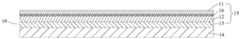
参考图7,图7所示为本发明实施例提供的灯箱布10的剖视图。其中,灯箱布10包括薄膜层11、反射层12、基材层13以及布料层14。该薄膜层11、反射层12、基材层13以及布料层14依次层叠设置。Referring to FIG. 7, FIG. 7 is a cross-sectional view of the
其中,薄膜层11为可以通过可见光的薄膜。薄膜层11的材质可以为聚乙烯、聚丙烯、聚氯乙烯、聚苯乙烯或树脂等材质。薄膜层11覆盖反射层12。薄膜层11可以为反射层12提供保护作用。例如,薄膜层11可以为反射层12提供防尘作用,薄膜层11使得反射层12隔绝空气从而使反射层12具备防腐蚀功能。在一些实施例中,薄膜层11可以为透明薄膜。Wherein, the
在一些实施例中,可以在薄膜层11中添加调色剂,使得薄膜层11呈现出绿色或者蓝色等颜色。从而灯箱布10整体的颜色也呈现为与薄膜层11相同的颜色。In some embodiments, toner may be added to the
反射层12可以透过灯箱100内部的光源30所发射的可见光。反射层12的材质包括金属。反射层12可以是通过真空蒸镀或真空磁控溅射的方式设置在基材层13上,从而使得反射层12具备对可见光的反射效果。当可见光在反射层12发生反射时,灯箱布10的表面至少呈现金属光泽。金属光泽是指金属抛光后的表面所反射的光泽。在一些实施例中,反射层12的材质包括对可见光具有较高反射率的金属。其中,反射层12可以包括铬、铝、银、镍中的一种或多种。例如,反射层12可以为铝和银的合金。在一些实施例中,反射层12中还可以添加非金属材质。The
基材层13也可以透过可见光。基材层13为反射层12提供附着所需的基板。在一些实施例中,基材层13的材质为聚氯乙烯。在一些实施例中,可以在基材层13中添加调色剂,使得基材层13呈现出与薄膜层11相同的颜色。当薄膜层11为透明薄膜时,灯箱布10整体的颜色呈现为与基材层13相同的颜色。The
布料层14可以透过可见光。布料层14的材质可以为纤维、聚酯(涤纶)、聚酰胺(尼龙,又称锦纶)、聚丙烯腈(腈纶)、聚氨酯(氨纶)等材料。The
由于灯箱布10中设置有反射层12,因此灯箱布10可以反射外部光线,从而灯箱布10表面能够呈现金属光泽。从灯箱布10外部的不同角度观察时,灯箱布10能够呈现出渐变的色彩效果。Since the
在一些实施例中,薄膜层11、反射层12以及基材层13可以通过粘结剂以不可逆方式粘合以形成一透光膜层15。其中,不可逆方式指的是透光膜层15形成后,不可再分离出薄膜层11、反射层12和基材层13。In some embodiments, the
在一些实施例中,如图8所示,薄膜层11和反射层12之间设置有粘结剂层16。薄膜层11和反射层12通过粘结剂层16粘合在一起。其中,薄膜层11、粘结剂层16、反射层12以及基材层13粘合以形成透光膜层15。In some embodiments, as shown in FIG. 8 , an
在一些实施例中,如图9所示,透光膜层15与布料层14之间设置有压敏胶17。透光膜层15与布料层14通过压敏胶17互相粘合。In some embodiments, as shown in FIG. 9 , a pressure-
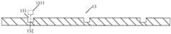
请参阅图10,图10是本发明实施例提供的灯箱布中的基材层的第一种结构示意图。其中,基材层13上设置有凹槽131,该凹槽131设置在基材层13朝向该布料层14的一侧,该凹槽131的形状可以为正方形。该增光膜1311设置在该凹槽131之中,该增光膜1311的形状与该凹槽131适配,以使得增光膜1311覆盖该凹槽131的底部,用于当面光源开启时,将光源发出的光向薄膜层11方向聚集,可以提高灯箱的整体亮度。Please refer to FIG. 10 . FIG. 10 is a schematic diagram of the first structure of the base material layer in the light box cloth provided by the embodiment of the present invention. Wherein, the
在一些实施例中,该凹槽131底部可以设置有粘接层,所述增光膜1311可以通过所述粘接层设置在所述凹槽131上。In some embodiments, an adhesive layer may be disposed at the bottom of the
在一些实施例中,如图11所示,该凹槽131的形状还可以为圆弧形,对应的,该增光膜1311的形状也设置为圆弧状,以使得可以覆盖该凹槽131。In some embodiments, as shown in FIG. 11 , the shape of the
在一些实施例中,如图12所示,该凹槽131中还包括有第一增光膜1311以及第二增光膜1312,该第一增光膜1311以及该第二增光膜1312的形状为正方形片状,大小与凹槽131适配,该第一增光膜1311设置在该凹槽131的底部,该第二增光膜1312设置在该凹槽131的侧壁上,且该第一增光膜1311与该第二增光膜1312互为垂直正交。通过将该第一增光膜1311与该第二增光膜1312设置互为垂直正交,可以将光源发出的光循环利用,更好的提高灯箱的整体亮度。In some embodiments, as shown in FIG. 12 , the
在一些实施例中,如图13所示,该粘接层132设置在该凹槽131的底部上,该增光膜1311通过该粘接层132设置在该凹槽131上以进行固定。In some embodiments, as shown in FIG. 13 , the
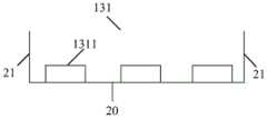
请参阅图14,图14是本发明实施例提供的灯箱布中的基材层的凹槽的第一种结构示意图。其中,凹槽131包括底部20以及侧壁21。该凹槽131底部20设置多个增光膜1311,该多个增光膜1311相互间隔设置。在一实施方式中,该凹槽131底部20设置有粘接层,该多个增光膜1311通过该粘接层粘接在凹槽131的底部上。Please refer to FIG. 14 . FIG. 14 is a schematic diagram of the first structure of the groove of the substrate layer in the light box cloth provided by the embodiment of the present invention. Wherein, the
在一些实施例中,如图15所示,该凹槽131底部20设置有一增光膜1311,该凹槽131的至少一个侧壁上21设置有增光膜1311。该底部20上的增光膜1311与侧壁上21上的增光膜1311互为垂直正交,可以将面光源发出的光循环利用,更好的提高灯箱的整体亮度。In some embodiments, as shown in FIG. 15 , a
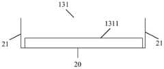
在一些实施例中,如图16所示,该凹槽131底部20设置有一增光膜1311,该增光膜1311的面积小于所述凹槽131底部20的面积,增光膜1311的两端与凹槽两端的侧壁21之间预设有间隔,以使得部分光线还可以通过间隔进行传递。In some embodiments, as shown in FIG. 16 , the bottom 20 of the
在一些实施例中,如图17所示,该凹槽131两端的侧壁21上各自设置有一增光膜1311。在一实施方式中,该两端的侧壁21上设置有粘接层,该增光膜1311通过该粘接层粘接在两端的侧壁上。In some embodiments, as shown in FIG. 17 , a
以上对本发明实施例提供的灯箱布及灯箱进行了详细介绍,本文中应用了具体个例对本发明的原理及实施方式进行了阐述,以上实施例的说明只是用于帮助理解本发明。同时,对于本领域的技术人员,依据本发明的思想,在具体实施方式及应用范围上均会有改变之处,综上所述,本说明书内容不应理解为对本发明的限制。The light box cloth and the light box provided by the embodiments of the present invention have been introduced in detail above. The principles and implementation methods of the present invention are explained by using specific examples in this paper. The descriptions of the above embodiments are only used to help understand the present invention. At the same time, for those skilled in the art, according to the idea of the present invention, there will be changes in the specific implementation and application scope. In summary, the content of this specification should not be construed as limiting the present invention.
Claims (15)
Translated fromChinesePriority Applications (1)
| Application Number | Priority Date | Filing Date | Title |
|---|---|---|---|
| CN201710625424.0ACN107256681B (en) | 2017-07-27 | 2017-07-27 | Lamp box cloth and lamp box |
Applications Claiming Priority (1)
| Application Number | Priority Date | Filing Date | Title |
|---|---|---|---|
| CN201710625424.0ACN107256681B (en) | 2017-07-27 | 2017-07-27 | Lamp box cloth and lamp box |
Publications (2)
| Publication Number | Publication Date |
|---|---|
| CN107256681A CN107256681A (en) | 2017-10-17 |
| CN107256681Btrue CN107256681B (en) | 2023-05-09 |
Family
ID=60025708
Family Applications (1)
| Application Number | Title | Priority Date | Filing Date |
|---|---|---|---|
| CN201710625424.0AExpired - Fee RelatedCN107256681B (en) | 2017-07-27 | 2017-07-27 | Lamp box cloth and lamp box |
Country Status (1)
| Country | Link |
|---|---|
| CN (1) | CN107256681B (en) |
Citations (3)
| Publication number | Priority date | Publication date | Assignee | Title |
|---|---|---|---|---|
| CN202847036U (en)* | 2012-09-25 | 2013-04-03 | 江阴东恒新材料科技有限公司 | Indoor lamp box fabric |
| KR20160139912A (en)* | 2015-05-29 | 2016-12-07 | 현대자동차주식회사 | Integral rear reflector |
| EP3104664A1 (en)* | 2015-06-10 | 2016-12-14 | Electrolux Appliances Aktiebolag | Hob comprising heating zone illumination means |
Family Cites Families (14)
| Publication number | Priority date | Publication date | Assignee | Title |
|---|---|---|---|---|
| JP3700611B2 (en)* | 2001-06-07 | 2005-09-28 | セイコーエプソン株式会社 | Transflective electro-optical device and electronic apparatus |
| US7160017B2 (en)* | 2004-06-03 | 2007-01-09 | Eastman Kodak Company | Brightness enhancement film using a linear arrangement of light concentrators |
| JP2006047939A (en)* | 2004-08-06 | 2006-02-16 | Showa Boeki Kk | Advertising device |
| WO2008008994A2 (en)* | 2006-07-14 | 2008-01-17 | Light Prescriptions Innovators, Llc | Brightness-enhancing film |
| JP5683421B2 (en)* | 2011-09-27 | 2015-03-11 | 株式会社ジャパンディスプレイ | Lighting device |
| CN104536070B (en)* | 2015-01-15 | 2018-02-27 | 张家港康得新光电材料有限公司 | The preparation method of optical thin film and optical thin film |
| WO2017079392A1 (en)* | 2015-11-06 | 2017-05-11 | 10X Technology Llc | Retroreflective traffic sign and process and apparatus for manufacturing same |
| CN205282017U (en)* | 2015-12-16 | 2016-06-01 | 四川新力光源股份有限公司 | Energy -saving advertising lamp box |
| CN205606476U (en)* | 2016-03-22 | 2016-09-28 | 深圳市联创德科技有限公司 | A glue frame structure for solving an ultra -thin backlight knot position bright spot |
| CN205685875U (en)* | 2016-06-06 | 2016-11-16 | 江阴市宇源塑化有限公司 | Lamp house cloth |
| CN206270640U (en)* | 2016-11-22 | 2017-06-20 | 信利(惠州)智能显示有限公司 | Optical projection external member |
| CN206270632U (en)* | 2016-11-22 | 2017-06-20 | 信利(惠州)智能显示有限公司 | Projection structure |
| CN106827743A (en)* | 2017-03-10 | 2017-06-13 | 深圳市武士贸易有限公司 | Surface coating structure with metal photosphere high |
| CN207020932U (en)* | 2017-07-27 | 2018-02-16 | 广东欧珀移动通信有限公司 | Lamp house cloth and lamp box |
- 2017
- 2017-07-27CNCN201710625424.0Apatent/CN107256681B/ennot_activeExpired - Fee Related
Patent Citations (3)
| Publication number | Priority date | Publication date | Assignee | Title |
|---|---|---|---|---|
| CN202847036U (en)* | 2012-09-25 | 2013-04-03 | 江阴东恒新材料科技有限公司 | Indoor lamp box fabric |
| KR20160139912A (en)* | 2015-05-29 | 2016-12-07 | 현대자동차주식회사 | Integral rear reflector |
| EP3104664A1 (en)* | 2015-06-10 | 2016-12-14 | Electrolux Appliances Aktiebolag | Hob comprising heating zone illumination means |
Also Published As
| Publication number | Publication date |
|---|---|
| CN107256681A (en) | 2017-10-17 |
Similar Documents
| Publication | Publication Date | Title |
|---|---|---|
| CN118408170A (en) | Light emitting device, display device, and lighting device | |
| CN107062113A (en) | Light-emitting device | |
| CN102121606A (en) | Light-emitting unit and backlight module | |
| CN207020932U (en) | Lamp house cloth and lamp box | |
| CN107263981A (en) | Lamp house cloth and lamp box | |
| CN206968138U (en) | Lamp house cloth and lamp box | |
| CN206968133U (en) | Lamp house cloth and lamp box | |
| CN107274802B (en) | Light box cloth and light box | |
| CN107256681B (en) | Lamp box cloth and lamp box | |
| CN207115936U (en) | Lamp house cloth and lamp box | |
| CN206931338U (en) | Lamp house cloth and lamp box | |
| CN206968119U (en) | Lamp house cloth and lamp box | |
| CN107331319B (en) | Light box fabric components and light boxes | |
| CN206968132U (en) | Lamp house cloth and lamp box | |
| CN107175875A (en) | Lamp house cloth and lamp box | |
| CN207020931U (en) | Lamp house cloth component and lamp box | |
| CN207020933U (en) | Lamp box | |
| CN206931333U (en) | Lamp house cloth and lamp box | |
| CN206931335U (en) | Lamp house cloth and lamp box | |
| CN107134229A (en) | Lamp house cloth and lamp box | |
| CN107170386B (en) | Light box cloth and light box | |
| CN206931334U (en) | Lamp house cloth and lamp box | |
| CN107300158A (en) | Lamp house cloth and lamp box | |
| CN206931336U (en) | Lamp house cloth and lamp box | |
| CN107283978A (en) | Lamp house cloth and lamp box |
Legal Events
| Date | Code | Title | Description |
|---|---|---|---|
| PB01 | Publication | ||
| PB01 | Publication | ||
| SE01 | Entry into force of request for substantive examination | ||
| SE01 | Entry into force of request for substantive examination | ||
| CB02 | Change of applicant information | ||
| CB02 | Change of applicant information | Address after:Changan town in Guangdong province Dongguan 523860 usha Beach Road No. 18 Applicant after:GUANGDONG OPPO MOBILE TELECOMMUNICATIONS Corp.,Ltd. Address before:Changan town in Guangdong province Dongguan 523860 usha Beach Road No. 18 Applicant before:GUANGDONG OPPO MOBILE TELECOMMUNICATIONS Corp.,Ltd. | |
| GR01 | Patent grant | ||
| GR01 | Patent grant | ||
| CF01 | Termination of patent right due to non-payment of annual fee | ||
| CF01 | Termination of patent right due to non-payment of annual fee | Granted publication date:20230509 |