CN107251263B - Battery cell and battery system - Google Patents
Battery cell and battery systemDownload PDFInfo
- Publication number
- CN107251263B CN107251263BCN201680007826.8ACN201680007826ACN107251263BCN 107251263 BCN107251263 BCN 107251263BCN 201680007826 ACN201680007826 ACN 201680007826ACN 107251263 BCN107251263 BCN 107251263B
- Authority
- CN
- China
- Prior art keywords
- holder
- collector
- battery cell
- electrode winding
- winding
- Prior art date
- Legal status (The legal status is an assumption and is not a legal conclusion. Google has not performed a legal analysis and makes no representation as to the accuracy of the status listed.)
- Expired - Fee Related
Links
Images


Classifications
- H—ELECTRICITY
- H01—ELECTRIC ELEMENTS
- H01M—PROCESSES OR MEANS, e.g. BATTERIES, FOR THE DIRECT CONVERSION OF CHEMICAL ENERGY INTO ELECTRICAL ENERGY
- H01M10/00—Secondary cells; Manufacture thereof
- H01M10/04—Construction or manufacture in general
- H01M10/0486—Frames for plates or membranes
- H—ELECTRICITY
- H01—ELECTRIC ELEMENTS
- H01M—PROCESSES OR MEANS, e.g. BATTERIES, FOR THE DIRECT CONVERSION OF CHEMICAL ENERGY INTO ELECTRICAL ENERGY
- H01M10/00—Secondary cells; Manufacture thereof
- H01M10/04—Construction or manufacture in general
- H01M10/0431—Cells with wound or folded electrodes
- H—ELECTRICITY
- H01—ELECTRIC ELEMENTS
- H01M—PROCESSES OR MEANS, e.g. BATTERIES, FOR THE DIRECT CONVERSION OF CHEMICAL ENERGY INTO ELECTRICAL ENERGY
- H01M50/00—Constructional details or processes of manufacture of the non-active parts of electrochemical cells other than fuel cells, e.g. hybrid cells
- H01M50/10—Primary casings; Jackets or wrappings
- H01M50/102—Primary casings; Jackets or wrappings characterised by their shape or physical structure
- H01M50/103—Primary casings; Jackets or wrappings characterised by their shape or physical structure prismatic or rectangular
- H—ELECTRICITY
- H01—ELECTRIC ELEMENTS
- H01M—PROCESSES OR MEANS, e.g. BATTERIES, FOR THE DIRECT CONVERSION OF CHEMICAL ENERGY INTO ELECTRICAL ENERGY
- H01M50/00—Constructional details or processes of manufacture of the non-active parts of electrochemical cells other than fuel cells, e.g. hybrid cells
- H01M50/10—Primary casings; Jackets or wrappings
- H01M50/172—Arrangements of electric connectors penetrating the casing
- H01M50/174—Arrangements of electric connectors penetrating the casing adapted for the shape of the cells
- H01M50/176—Arrangements of electric connectors penetrating the casing adapted for the shape of the cells for prismatic or rectangular cells
- H—ELECTRICITY
- H01—ELECTRIC ELEMENTS
- H01M—PROCESSES OR MEANS, e.g. BATTERIES, FOR THE DIRECT CONVERSION OF CHEMICAL ENERGY INTO ELECTRICAL ENERGY
- H01M50/00—Constructional details or processes of manufacture of the non-active parts of electrochemical cells other than fuel cells, e.g. hybrid cells
- H01M50/40—Separators; Membranes; Diaphragms; Spacing elements inside cells
- H—ELECTRICITY
- H01—ELECTRIC ELEMENTS
- H01M—PROCESSES OR MEANS, e.g. BATTERIES, FOR THE DIRECT CONVERSION OF CHEMICAL ENERGY INTO ELECTRICAL ENERGY
- H01M50/00—Constructional details or processes of manufacture of the non-active parts of electrochemical cells other than fuel cells, e.g. hybrid cells
- H01M50/50—Current conducting connections for cells or batteries
- H01M50/531—Electrode connections inside a battery casing
- H01M50/533—Electrode connections inside a battery casing characterised by the shape of the leads or tabs
- H—ELECTRICITY
- H01—ELECTRIC ELEMENTS
- H01M—PROCESSES OR MEANS, e.g. BATTERIES, FOR THE DIRECT CONVERSION OF CHEMICAL ENERGY INTO ELECTRICAL ENERGY
- H01M2220/00—Batteries for particular applications
- H01M2220/20—Batteries in motive systems, e.g. vehicle, ship, plane
- Y—GENERAL TAGGING OF NEW TECHNOLOGICAL DEVELOPMENTS; GENERAL TAGGING OF CROSS-SECTIONAL TECHNOLOGIES SPANNING OVER SEVERAL SECTIONS OF THE IPC; TECHNICAL SUBJECTS COVERED BY FORMER USPC CROSS-REFERENCE ART COLLECTIONS [XRACs] AND DIGESTS
- Y02—TECHNOLOGIES OR APPLICATIONS FOR MITIGATION OR ADAPTATION AGAINST CLIMATE CHANGE
- Y02E—REDUCTION OF GREENHOUSE GAS [GHG] EMISSIONS, RELATED TO ENERGY GENERATION, TRANSMISSION OR DISTRIBUTION
- Y02E60/00—Enabling technologies; Technologies with a potential or indirect contribution to GHG emissions mitigation
- Y02E60/10—Energy storage using batteries
- Y—GENERAL TAGGING OF NEW TECHNOLOGICAL DEVELOPMENTS; GENERAL TAGGING OF CROSS-SECTIONAL TECHNOLOGIES SPANNING OVER SEVERAL SECTIONS OF THE IPC; TECHNICAL SUBJECTS COVERED BY FORMER USPC CROSS-REFERENCE ART COLLECTIONS [XRACs] AND DIGESTS
- Y02—TECHNOLOGIES OR APPLICATIONS FOR MITIGATION OR ADAPTATION AGAINST CLIMATE CHANGE
- Y02P—CLIMATE CHANGE MITIGATION TECHNOLOGIES IN THE PRODUCTION OR PROCESSING OF GOODS
- Y02P70/00—Climate change mitigation technologies in the production process for final industrial or consumer products
- Y02P70/50—Manufacturing or production processes characterised by the final manufactured product
Landscapes
- Chemical & Material Sciences (AREA)
- Chemical Kinetics & Catalysis (AREA)
- Electrochemistry (AREA)
- General Chemical & Material Sciences (AREA)
- Engineering & Computer Science (AREA)
- Manufacturing & Machinery (AREA)
- Connection Of Batteries Or Terminals (AREA)
- Secondary Cells (AREA)
- Sealing Battery Cases Or Jackets (AREA)
- Battery Mounting, Suspending (AREA)
Abstract
Description
Translated fromChinese本发明涉及一种电池单池以及一种电池系统。The present invention relates to a battery cell and a battery system.
背景技术Background technique
表明的是,在将来,不仅在静止的应用情况(比如风力涡轮机,在被设计为混合动力车辆或者电动车辆的机动车中)而且在电子设备中(比如笔记本电脑或者移动电话)都使用新的电池系统,在可靠性、安全性、效率和使用寿命方面对所述新的电池系统提出很高的要求。It shows that in the future, the new technology will be used not only in stationary applications (eg wind turbines, in motor vehicles designed as hybrid or electric vehicles) but also in electronic devices (eg notebook computers or mobile phones) The battery system places high demands on the new battery system in terms of reliability, safety, efficiency and service life.
在此,尤其使用所谓的锂-离子-电池单池。这些锂离子-电池单池的突出之处除其他外在于高的能量密度、热稳定性和极低的自动放电。锂-离子-电池单池具有正电极和负电极,在充电过程中并且在放电过程中,锂-离子能够在所述正电极和负电极处可逆地移入并且重又移出。这样的过程也被称为嵌入或者脱嵌。Here, in particular so-called lithium-ion battery cells are used. These lithium-ion-battery cells are distinguished, among other things, by high energy density, thermal stability and extremely low self-discharge. Lithium-ion-battery cells have positive and negative electrodes at which lithium-ions can be reversibly moved in and out again during charging and during discharging. Such a process is also known as embedding or de-embedding.
电池单池通常包括一个或者多个电极单元,所述电极单元以绕组的形式来构造。电极单元具有两个薄片状构造的电极、也就是一个阳极和一个阴极。所述电极在中间放置分隔件的情况下被卷成也被称为胶质-卷(Jelly-Roll)的电极绕组。所述电极绕组的两个电极借助于收集器与所述电池单池的、也被称为端子的极进行电连接。A battery cell usually includes one or more electrode units, which are designed in the form of windings. The electrode unit has two electrodes of sheet-like configuration, namely an anode and a cathode. The electrodes are rolled with a separator in between to form an electrode winding, also called a Jelly-Roll. The two electrodes of the electrode winding are electrically connected by means of collectors to the poles of the battery cells, also referred to as terminals.
此外,电池单池具有比如由铝制成的单池壳体。该单池壳体通常棱柱形地、尤其是矩形地构造,并且耐压地构造。在将所述电极与所述端子连接之后,将电解质溶液填充到所述单池壳体中。In addition, the battery cells have a cell housing made of aluminum, for example. The cell housing is generally of prismatic, in particular rectangular, and pressure-resistant design. After connecting the electrodes to the terminals, an electrolyte solution is filled into the cell case.
由EP 2 675 000 A1公开了一种所述类型的、具有多个电极绕组的电池单池。阳极和阴极在此在相反的侧面处平行于绕组轴线从所述电极绕组中伸出来,并且被连接到相应的收集器处。所述两个收集器基本上垂直于所述电极绕组的绕组轴线地延伸,并且将所述阳极和阴极与所述端子连接。A battery cell of the type described with a plurality of electrode windings is known from
由US 2010/0028770 A1公开了另一种所述类型的电池单池。电极绕组的电极具有接触件,所述接触件从所述电极绕组中伸出来并且与收集器相连接。在与所述收集器连接之前,所述接触件具有不同的长度。Another battery cell of the type described is disclosed by US 2010/0028770 A1. The electrodes of the electrode winding have contacts which protrude from the electrode winding and are connected to the collector. The contacts have different lengths before being connected to the collector.
为了使所述电极和所述单池壳体电绝缘而设置了绝缘体,所述绝缘体比如由塑料制成。在US 2013/0288092 A1中描述了一种具有相应用于电池单池的绝缘体的电极绕组。To electrically insulate the electrodes from the cell housing, an insulator is provided, which is made of plastic, for example. An electrode winding with corresponding insulators for battery cells is described in US 2013/0288092 A1.
锂-离子-电池单池对于环境影响、尤其对于空气和潮湿相对来说敏感。所提到的单池壳体提供了针对所提到的环境影响的保护。这样的电池单池中的多个电池单池能够合并成也被称为电池包的电池系统。Lithium-ion-battery cells are relatively sensitive to environmental influences, especially to air and moisture. The mentioned cell housing provides protection against the mentioned environmental influences. A plurality of such battery cells can be combined into a battery system also referred to as a battery pack.
发明内容SUMMARY OF THE INVENTION
提出了一种电池单池,该电池单池包括棱柱形地构造的单池壳体和布置在所述单池壳体之内的至少一个电极绕组,该单池壳体具有盖罩面,负端子和正端子被布置在该盖罩面处,该电极绕组包括阴极和阳极。A battery cell is proposed comprising a prismatic cell housing and at least one electrode winding arranged within the cell housing, the cell housing having a cover surface, a negative Terminals and a positive terminal are arranged at the cover surface, and the electrode winding includes a cathode and an anode.
根据本发明,所述至少一个电极绕组借助电绝缘的保持件被固定在所述盖罩面处,其中,所述保持件与至少一个电绝缘的间隔保持件连接。According to the invention, the at least one electrode winding is fastened to the cover surface by means of an electrically insulating holder, wherein the holder is connected to at least one electrically insulating spacer.
在此,有利地,所述间隔保持件被固定在所述盖罩面处。Here, the spacer is advantageously fastened on the cover surface.
优选地,所述间隔保持件被收集器保持(尤其是夹持)在所述盖罩面处,该收集器将所述阴极或者所述阳极与端子电连接。Preferably, the spacer is held (in particular clamped) at the cover surface by a collector which electrically connects the cathode or the anode to a terminal.
根据本发明的一种有利的方案,所述保持件被框架状地实施,并且,所述至少一个电极绕组被夹紧到所述保持件中。According to an advantageous development of the invention, the holder is frame-shaped and the at least one electrode winding is clamped into the holder.
在此,优选地,绕组轴线平行于所述单池壳体的盖罩面地延伸,所述电极绕组围绕该绕组轴线被缠绕。In this case, preferably, the winding axis, around which the electrode winding is wound, extends parallel to the cover surface of the cell housing.
根据本发明的另一种有利的方案,所述保持件具有盖罩区域和底部区域,该盖罩区域与所述间隔保持件连接,该底部区域与所述盖罩区域连接,并且,所述至少一个电极绕组被保持在所述盖罩区域和所述底部区域之间。According to another advantageous development of the invention, the holder has a cover area and a base area, the cover area is connected to the spacer, the base area is connected to the cover area, and the At least one electrode winding is held between the cover region and the base region.
在此,所述至少一个电极绕组被所述保持件至少近似完全地包围。In this case, the at least one electrode winding is surrounded at least approximately completely by the holder.
根据本发明的另一种有利的方案,所述保持件被实施为扁平的物体,并且,所述至少一个电极绕组绕着所述保持件被缠绕。According to a further advantageous development of the invention, the holder is embodied as a flat object and the at least one electrode winding is wound around the holder.
在此,优选地,绕组轴线垂直于所述单池壳体的盖罩面地延伸,所述至少一个电极绕组围绕该绕组轴线被缠绕。In this case, preferably, the winding axis, around which the at least one electrode winding is wound, extends perpendicularly to the cover surface of the cell housing.
根据本发明的另一种有利的方案,所述保持件以双框架的形式被实施。在此,所述保持件包括第一框架部件以及第二框架部件,该第一框架部件和该第二框架部件在它们之间接收所述至少一个电极绕组。According to another advantageous development of the invention, the holder is embodied in the form of a double frame. Here, the holder comprises a first frame part and a second frame part, the first frame part and the second frame part receiving the at least one electrode winding therebetween.
有利地并且装配友好地,所述保持件与所述至少一个电绝缘的间隔保持件一体地被构造。Advantageously and assembly-friendly, the holder is formed in one piece with the at least one electrically insulating spacer.
也提出了一种电池系统,该电池系统包括至少一个根据本发明的电池单池。A battery system is also proposed which comprises at least one battery cell according to the invention.
有利地,根据本发明的电池单池在电动车辆(EV)中、在混合动力车辆(HEV)中或者在插电式混合动力车辆(PHEV)中得到应用。Advantageously, the battery cells according to the invention find application in electric vehicles (EVs), in hybrid electric vehicles (HEVs) or in plug-in hybrid electric vehicles (PHEVs).
发明优点Invention Advantages
有利地,所述电池单池的装配被简化,当所述至少一个电极绕组被固定在保持件处时,该保持件在所述单池壳体的盖罩面处。在将所述盖罩面接合在剩余的单池壳体上时,所述至少一个电极绕组自动地被导入所述单池壳体的内部中。为了固定所述保持件,使用了间隔保持件,所述间隔保持件已经是存在的并且用于所述收集器相对于所述单池壳体的绝缘。在此,所述的收集器将所述间隔保持件机械地固定在所述盖罩面处,并且,将所述间隔保持件夹紧在所述盖罩面处,所述收集器将所述阴极以及所述阳极与所述电池单池的所述端子连接。Advantageously, the assembly of the battery cells is simplified when the at least one electrode winding is fastened to a holder on the cover surface of the cell housing. When the cover surface is attached to the remaining cell housing, the at least one electrode winding is automatically introduced into the interior of the cell housing. To fix the holder, spacers are used, which are already present and serve for the insulation of the collector relative to the cell housing. In this case, the collector mechanically fixes the spacer on the cover surface and clamps the spacer on the cover surface, the collector attaches the spacer The cathode and the anode are connected to the terminals of the battery cells.
附图说明Description of drawings
参照附图和下面的描写,本发明的实施方式被更详细地阐述。Embodiments of the present invention are explained in more detail with reference to the accompanying drawings and the following description.
附图示出:The attached figure shows:
图1 无收集器的电池单池的示意性的、立体的、半透明的图示,Figure 1 Schematic, three-dimensional, translucent representation of a battery cell without a collector,
图2 无电极绕组的、根据第一实施方式的电池单池的示意性的、立体的、半透明的图示,2 is a schematic, three-dimensional, translucent representation of a battery cell according to a first embodiment without electrode windings,
图3 无电极绕组的、根据第二实施方式的电池单池的示意性的、立体的、半透明的图示,3 is a schematic, three-dimensional, translucent representation of a battery cell according to a second embodiment without electrode windings,
图4 在装入单池壳体中之前的电极绕组的端侧的俯视图,Fig. 4 Top view of the end side of the electrode winding before insertion into the cell housing,
图5a 在与收集器连接之前的、沿切线V-V的、来自图4的电极绕组的局部剖视图,Figure 5a is a partial cross-sectional view of the electrode winding from Figure 4, taken along tangent V-V, prior to connection with the collector,
图5b 在与收集器连接之后的、来自图5a的电极绕组,Figure 5b Electrode winding from Figure 5a after connection to the collector,
图6a 在与收集器连接之前的、来自图5a的电极绕组的变型,Fig. 6a Variation of the electrode winding from Fig. 5a before connection to the collector,
图6b 在与收集器连接之后的、来自图6a的电极绕组,Figure 6b Electrode winding from Figure 6a after connection to the collector,
图7 电极绕组的制造的示意图,Figure 7 Schematic diagram of the fabrication of electrode windings,
图8 具有用于电极绕组的保持件的第一实施方式的电池单池的示意性剖视图,8 is a schematic cross-sectional view of a battery cell of a first embodiment with a holder for the electrode winding,
图9 具有用于电极绕组的保持件的第二实施方式的电池单池的示意性剖视图,9 is a schematic cross-sectional view of a battery cell with a second embodiment of a holder for electrode windings,
图10 具有用于电极绕组的保持件的第三实施方式的电池单池的示意性剖视图,10 is a schematic cross-sectional view of a battery cell with a third embodiment of a holder for electrode windings,
图11 具有用于电极绕组的保持件的第四实施方式的电池单池的示意性爆炸图,以及Figure 11 is a schematic exploded view of a fourth embodiment of a battery cell with holders for electrode windings, and
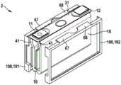
图12 在组装单池壳体时的、来自图11的电池单池的示意性立体图。FIG. 12 is a schematic perspective view of the battery cell from FIG. 11 when the cell housing is assembled.
具体实施方式Detailed ways
电池单池2包括单池壳体3,该单池壳体棱柱形地、当前矩形地被构造。当前,单池壳体3导电地被实施,并且,例如由铝制成。也能够设想的是,单池壳体3由电绝缘的材料(例如塑料)制成或者涂覆有电绝缘材料。The
电池单池2包括负端子11和正端子12。由电池单池2提供的电压能够通过端子11、12被截取。此外,电池单池2也能够通过端子11、12被充电。The
电池单池2的、矩形地构造的单池壳体3具有六个面,所述六个面具有三种不同大小的面积,其中,具有相同大小的面积的两个面分别彼此对置。在下文中,具有最大面积的面被称为第一正面33和第二正面34。在下文中,具有最小面积的面被称为第一端面35和第二端面36。在下文中,剩下的、具有中等大小面积的面被称为盖罩面31和底面32。The rectangularly designed
端子11、12彼此间隔地被布置在单池壳体3的盖罩面31处。在此,负端子11与第一端面35相邻,并且,正端子12与第二端面36相邻。The
电极绕组10被布置在电池单池2的单池壳体3之内,该电极绕组具有两个电极,即阴极14和阳极16。阴极14和阳极16被薄片状地实施,并且,在中间放置第一分隔件18和第二分隔件19的情况下,围绕绕组轴线A被缠绕成电极绕组10。电极绕组10被如此布置在单池壳体3中,使得绕组轴线A垂直于端面35、36地延伸。Arranged within the
也能够设想的是,电池单池2包括多个电极绕组10,所述电极绕组并联或者(在有足够的绝缘时)串联电连接。此外,在单池壳体3之内存在电解质。It is also conceivable that the
阳极16具有多个阳极接触件26,所述阳极接触件与电池单池2的负端子11电连接。阴极14具有多个阴极接触件24,所述阴极接触件与电池单池2的正端子12电连接。阳极接触件26和阴极接触件24彼此并排地在同一个端侧处从电极绕组10中突出,并且,从电极绕组10朝向单池壳体3的第一端面35延伸。The
这里未示出的绝缘薄片被布置在电极绕组10的阳极接触件26和阴极接触件24之间,该绝缘薄片将阳极16的阳极接触件26与阴极14的阴极接触件24电绝缘。当前,所述绝缘薄片是分隔件18、19之一的部分,所述分隔件被设置在电极绕组10的阳极16和阴极14之间。An insulating foil, not shown here, is arranged between the
第一收集器41被设置用于将阳极16与负端子11电连接。第一收集器41具有第一区域42,该第一区域平行于第一端面35并且靠近第一端面35地延伸,并且,与阳极16的阳极接触件26连接。第一收集器41的第一区域42朝向盖罩面31地延伸,并且,过渡至第二区域43,该第二区域平行于盖罩面31地延伸。第一收集器41的第二区域43与负端子11连接。电绝缘体被设置在第一收集器41和电池单池2的单池壳体3之间。The
第二收集器51被设置用于将阴极14与正端子12电连接。第二收集器51具有第一区域52,该第一区域平行于第一端面35靠近第一端面35地延伸,并且与阴极14的阴极接触件24连接。第二收集器51具有第二区域53,该第二区域与正端子12连接。The
根据电池单池2的第一实施方式(该实施方式在图2中被示出),第二收集器51具有中部区域55,该中部区域与第一区域52并且与第二区域53连接。在此,第二收集器51的中部区域55平行于正面33、34地延伸。当前,第二收集器51的中部区域55被布置在电极绕组10和第一正面33之间。电绝缘体被设置在第二收集器51和电池单池2的单池壳体3之间。According to the first embodiment of the
第二收集器51的中部区域55也能够被布置在电极绕组10和第二正面34之间。第二收集器51的两个平行延伸的中部区域55也能够被设置,所述两个平行延伸的中部区域被布置在电极绕组10的两侧上。The
根据电池单池2的第二实施方式(该实施方式在图3中被示出),第二收集器51具有下部区域56,该下部区域与第一区域52连接。此外,第二收集器51具有后部区域57,该后部区域与第二区域53连接。在此,第二收集器51的下部区域56与第二收集器51的后部区域57连接。According to the second embodiment of the
第二收集器51的下部区域56平行于底面32、在电极绕组10和底面32之间、从第二收集器51的第一区域52朝向第二端面36地延伸。第二收集器51的后部区域57平行于第二端面36、在电极绕组10和第二端面36之间、从第二收集器51的第二区域53朝向底面32地延伸。此外,第二收集器51后部区域57与第二收集器51的下部区域56连接。电绝缘体同样被设置在第二收集器51和电池单池2的单池壳体3之间。The
根据电池单池2的(这里未示出的)另一实施方式,导电的单池壳体3与正端子12电连接。在这种情况下,在第二收集器51和单池壳体3之间不需要绝缘体。According to a further embodiment of the battery cell 2 (not shown here), the electrically
可替代地,导电的单池壳体3与负端子11电连接。在这种情况下,在第一收集器41和单池壳体3之间不需要绝缘体。Alternatively, the electrically
此外,能够设想的是,将正端子12以及阴极14的阴极接触件24与单池壳体3电连接。在这种情况下,单池壳体3承担了第二收集器51的功能,即阴极14与正端子12的电连接。在这种情况下,第二收集器51能够整个被取消。也能够设想的是,第二收集器51将阴极14的阴极接触件24与单池壳体3的第一端面35电连接。Furthermore, it is conceivable to electrically connect the
可替代地,能够设想的是,将负端子11以及阳极16的阳极接触件26与单池壳体3电连接。在这种情况下,单池壳体3承担了第一收集器41的功能,即阳极14与负端子11的电连接。在这种情况下,第一收集器41能够整个被取消。也能够设想的是,第一收集器41将阳极16的阳极接触件26例如与单池壳体3的第一端面35电连接。Alternatively, it is conceivable to electrically connect the
在图4中,在装入电池单池2的单池壳体中3之前的电极绕组10的端侧的俯视图被示出。阳极16的阳极接触件26近似平行于绕组轴线A地从电极绕组10中突出。在垂直于绕组轴线A的方向上,阳极16的阳极接触件26彼此对准地被布置在一条线上。阴极14的阴极接触件24近似平行于绕组轴线A地从电极绕组10中突出。在垂直于绕组轴线A的方向上,阴极14的阴极接触件24彼此对准地被布置在一条线上。In FIG. 4 , a top view of the end side of the electrode winding 10 is shown before being inserted into the
在图5a中,沿切线V-V的、来自图4的电极绕组10的局部剖视图被示出。在此,在与第二收集器51连接之前,电极绕组10的、具有阴极14的阴极接触件24的部分被示出。在此,第二收集器51垂直于电极绕组10的绕组轴线A地延伸。In Fig. 5a, a partial cross-sectional view of the electrode winding 10 from Fig. 4, taken along the tangent V-V, is shown. Here, the part of the electrode winding 10 with the cathode contact 24 of the
在此,阴极14的各个阴极接触件24具有不同的长度。面对绕组轴线A的阴极接触件24具有最小的长度。阴极接触件24的长度随着阴极接触件24至绕组轴线A的增长的距离而增长。背离绕组轴线A的阴极接触件24具有最大的长度。Here, the individual cathode contacts 24 of the
在图5b中,在与第二收集器51连接之后的、来自图5a的电极绕组10被示出。阴极14的各个阴极接触件24分别围绕轴弯曲并且彼此叠置,该轴垂直于绕组轴线A地延伸。阴极14的、背离绕组轴线A的阴极接触件24被放置在第二收集器51上。阴极14的阴极接触件24彼此连接并且与第二收集器51连接,尤其是焊接。In Fig. 5b the electrode winding 10 from Fig. 5a is shown after connection with the
阴极14的各个阴极接触件24的长度被如此彼此协调,使得阴极接触件24的、背离电极绕组10的端部在阴极接触件24与第二收集器51连接后彼此对齐。The lengths of the individual cathode contacts 24 of the
在图6a中,在与第二收集器51连接之前的、来自图5a的电极绕组10的变型被示出。在此,第二收集器51平行于电极绕组10的绕组轴线A地延伸。In Fig. 6a a modification of the electrode winding 10 from Fig. 5a is shown prior to connection with the
就电极绕组10的所述的变型而言,阴极14的各个阴极接触件24具有不同的长度。面对绕组轴线A以及第二收集器51的阴极接触件24具有最小的长度。阴极接触件24的长度随着阴极接触件24至绕组轴线A以及至第二收集器51的增长的距离而增长。背离绕组轴线A以及第二收集器51的阴极接触件24具有最大的长度。With the described variant of the electrode winding 10, the individual cathode contacts 24 of the
在图6b中,在与第二收集器51连接之后的、来自图6a的电极绕组10被示出。阴极14的各个阴极接触件24彼此叠置。阴极14的、面对绕组轴线A的阴极接触件24被放置在第二收集器51上。阴极14的阴极接触件24彼此连接并且与第二收集器51连接,尤其是焊接。In Fig. 6b the electrode winding 10 from Fig. 6a is shown after connection with the
就电极绕组10的所述的变型而言,阴极14的各个阴极接触件24的长度被如此彼此协调,使得阴极接触件24的、背离电极绕组10的端部在阴极接触件24与第二收集器51连接后彼此对齐。With the described variant of the electrode winding 10 , the lengths of the individual cathode contacts 24 of the
在图7中,电极绕组10的制造被示意性地示出。绕组芯65围绕旋转轴线D旋转。薄片状构造的阴极14、薄片状构造的第一分隔件18、薄片状构造的阳极16和薄片状构造的第二分隔件19被固定在绕组芯65处。绕组芯65的旋转轴线D与电极绕组10的绕组轴线A对齐。In FIG. 7 the manufacture of the electrode winding 10 is shown schematically. The winding
通过绕组芯65的旋转,阴极14、第一分隔件18、阳极16和第二分隔件19被卷绕在绕组芯65上。因此,分隔件18、19之一位于阴极14和阳极16之间。By the rotation of the winding
第一激光束61将所述薄片状的阳极16的边缘区域切下。但是,在此所述阳极16的阳极接触件26保留下来。在分别使所述绕组芯65转动一整圈之后,所述阳极16的阳极接触件26之一保留下来。由此保证,所述阳极16的阳极接触件26如在图4中示出的那样彼此对齐地布置在一条线上。The
所述阳极16的保留下来的阳极接触件26的长度在此随着每次旋转而扩大。由此所述阳极16的、面对旋转轴线D以及绕组轴线A的阳极接触件26具有最小的长度,并且所述阳极16的、背离旋转轴线D以及绕组轴线A的阳极接触件26拥有最大的长度。The length of the remaining
第二激光束62将所述薄片状的阴极14的边缘区域切下。但是,在此所述阴极14的阴极接触件24保留下来。在分别使所述绕组芯65转动一整圈之后,所述阴极14的阴极接触件24之一保留下来。由此保证,所述阴极14的阴极接触件24如在图4中示出的那样彼此对齐地布置在一条线上。The
所述阴极14的保留下来的阴极接触件24的长度在此随着每次旋转而扩大。由此所述阴极14的、面对旋转轴线D和绕组轴线A的阴极接触件24拥有最小的长度,并且所述阴极14的、背离旋转轴线D和绕组轴线A的阴极接触件24如在图5a中示出的那样拥有最大的长度。The length of the remaining cathode contacts 24 of the
在完全卷起所述阴极14、所述阳极16和所述分隔件18、19之后,能够将所述绕组芯65移走。所述电极绕组10能够容易地被挤压到一起,由此将由于绕组芯65的缺少所引起的空腔闭合。After the
在图8中示出了电池单池2的示意性的剖面图,该电池单池具有用于电极绕组10的按照第一实施方式的保持件70。所述收集器41、51没有完整地示出。FIG. 8 shows a schematic sectional view of a
按照第一实施方式的保持件70实施为矩形的框架并且由不导电的材料、尤其是塑料制成。按照第一实施方式的保持件70包括第一纵侧面71和平行于所述第一纵侧面71延伸的第二纵侧面72。所述第一纵侧面71和所述第二纵侧面72在其端部上通过第一横侧面73和第二横侧面74彼此相连接。所述第一横侧面73和所述第二横侧面74彼此平行地延伸并且直角于所述纵侧面71、72地延伸。The
所述按照第一实施方式的框架状保持件70的第一纵侧面71被固定在所述电池单池2的单池壳体3的盖罩面31上。从所述按照第一实施方式的保持件70的第一纵侧面71的端部,所述第一横侧面73和所述第二横侧面74直角地远离所述盖罩面31地朝所述单池壳体3的未示出的底面32延伸。所述第一横侧面73在此在所述单池壳体3的未示出的第一端面35的附近延伸,并且所述第二横侧面74在所述单池壳体3的未示出的第二端面36的附近延伸。所述第二纵侧面72在所述单池壳体3的未示出的底面32的附近延伸。The first
所述电极绕组10被夹入到所述按照第一实施方式的框架状保持件70中。所述电极绕组10的绕组轴线A在此平行于所述按照第一实施方式的保持件70的纵侧面71、72地延伸,并且平行于单池壳体3的盖罩面31地延伸。所述阳极16和阴极14在所述按照第一实施方式的保持件70的第一横侧面73的附近从所述电极绕组10中伸出来。The electrode winding 10 is clamped into the frame-shaped
所述电池单池2的第一收集器41与所述负端子11进行了电与机械的连接。在所述第一收集器41与所述单池壳体3的盖罩面31之间布置了第一间隔保持件67。所述第一间隔保持件67由不导电的材料、尤其是由塑料制成,并且使所述第一收集器41与所述单池壳体3的盖罩面31电绝缘。所述第一间隔保持件67由此以机械的方式在所述单池壳体3的内部被固定在所述盖罩面31上。The
所述电池单池2的第二收集器51与所述正端子12进行了电和机械的连接。在所述第二收集器51与所述单池壳体3的盖罩面31之间布置了第二间隔保持件68。所述第二间隔保持件68由不导电的材料、尤其是由塑料制成,并且使所述第二收集器51与所述单池壳体3的盖罩面31电绝缘。所述第二间隔保持件68由此以机械的方式在所述单池壳体3的内部被固定在所述盖罩面31上。The
所述按照第一实施方式的保持件70的第一纵侧面71与所述第一间隔保持件67并且与所述第二间隔保持件68进行机械的连接。所述按照第一实施方式的保持件70的第一纵侧面71在此与卡夹连接相类似地被压入到所述间隔保持件67、68的相应的空隙中,并且形状配合地被保持在那里。也能够考虑,所述按照第一实施方式的保持件70与所述间隔保持件67、68一体地构造。The first
在图9中示出了电池单池2的示意性的剖面图,所述电池单池具有用于未示出的电极绕组10的按照第二实施方式的保持件80。所述收集器41、51未完整地示出。FIG. 9 shows a schematic sectional view of a
所述按照第二实施方式的保持件80以至少很大程度上封闭的罐的形式实施,并且由不导电的材料、尤其是由塑料制成。所述按照第二实施方式的保持件80包括盖罩区域81和底部区域82。The
所述按照第二实施方式的保持件80的盖罩区域81被固定在所述电池单池2的单池壳体3的盖罩面31上。在所示出的图示中,所述底部区域82远离所述盖罩区域81地布置。所述底部区域82在连接所述未示出的电极绕组10之后被挤压到所述盖罩区域81上,并且形状配合地卡锁在所述盖罩区域81处。未示出的电极绕组10此后被所述按照第二实施方式的、以罐的形式构造的保持件80所包围。The
所述电池单池2的第一收集器41与所述负端子11进行了电和机械的连接。在所述第一收集器41与所述单池壳体3的盖罩面31之间布置了第一间隔保持件67。所述第一间隔保持件67由不导电的材料、尤其是由塑料制成,并且使所述第一收集器41与所述单池壳体3的盖罩面31电绝缘。所述第一间隔保持件67由此以机械的方式在所述单池壳体3的内部被固定在所述盖罩面31处。The
所述电池单池2的第二收集器51与所述正端子12进行了电与机械的连接。在所述第二收集器51与所述单池壳体3的盖罩面31之间布置了第二间隔保持件68。所述第二间隔保持件68由不导电的材料、尤其是由塑料制成,并且使所述第二收集器51与所述单池壳体3的盖罩面31电绝缘。所述第二间隔保持件68由此以机械的方式在所述单池壳体3的内部被固定在所述盖罩面31处。The
所述按照第二实施方式的保持件80的盖罩区域81与所述第一间隔保持件67并且与所述第二间隔保持件68进行了机械连接。所述盖罩区域81包括盖板,所述盖板与卡夹连接相类似地被压入到所述间隔保持件67、68的相应的间隙中,并且形状配合地被保持在那里。也能够考虑,所述盖罩区域81与所述间隔保持件67、68一体地构造。The
在图10中示出了电池单池2的示意性的剖面图,所述电池单池具有用于未示出的电极绕组10的、按照第三实施方式的保持件90。所述收集器41、51未完整地示出。FIG. 10 shows a schematic sectional view of a
按照第三实施方式的保持件90实施为矩形的、面状的物体,并且由不导电的材料、尤其是由塑料制成。所述按照第三实施方式的保持件90被顶部侧91、平行于所述顶部侧91延伸的底部侧92、第一外侧93和第二外侧94限定。所述第一外侧面93和所述第二外侧面94彼此平行地并且直角于所述顶部侧91和所述底部侧92地延伸。The
所述按照第三实施方式的保持件90的顶部侧91被固定在所述电池单池2的单池壳体3的盖罩面31处。所述第一外侧面93和所述第二外侧面94直角地远离所述盖罩面31朝所述单池壳体3的未示出的底面32延伸。所述第一外侧面93在此在所述单池壳体3的未示出的第一端面35的附近延伸,并且所述第二外侧面94在所述单池壳体3的未示出的第二端面36的附近延伸。所述底部侧92在所述单池壳体3的未示出的底面32的附近延伸。The
所述未示出的电极绕组10围绕着所述按照第三实施方式的保持件90卷绕。所述电极绕组10的绕组轴线A在此直角于所述按照第三实施方式的保持件90的顶部侧91延伸,并且直角于所述单池壳体3的盖罩面31延伸。所述阳极16、所述阴极14以及所述分隔件18、19因此围绕着所述按照第三实施方式的保持件90的外侧面93、94放置。The electrode winding 10 (not shown) is wound around the
所述电池单池2的第一收集器41与所述负端子11进行电与机械的连接。在所述第一收集器41与所述单池壳体3的盖罩面31之间布置了第一间隔保持件67。所述第一间隔保持件67由不导电的材料、尤其是由塑料制成,并且使所述第一收集器41与所述单池壳体3的盖罩面31电绝缘。所述第一间隔保持件67由此以机械的方式在所述单池壳体3的内部被固定在所述盖罩面31处。The
所述电池单池2的第二收集器51与所述正端子12进行电与机械的连接。在所述第二收集器51与所述单池壳体3的盖罩面31之间布置了第二间隔保持件68。所述第二间隔保持件68由不导电的材料、尤其是由塑料制成,并且使所述第二收集器51与所述单池壳体3的盖罩面31电绝缘。所述第二间隔保持件68由此以机械的方式在所述单池壳体3的内部被固定在所述盖罩面31处。The
所述按照第三实施方式的保持件90的顶部侧91与所述第一间隔保持件67并且与所述第二间隔保持件68进行了机械连接。所述按照第三实施方式的保持件90的顶部侧91在此与卡夹连接相类似地被压入到所述间隔保持件67、68的相应的间隙中,并且形状配合地被保持在那里。也能够考虑,所述按照第三实施方式的保持件90与所述间隔保持件67、68一体地构造。The
在图11中,具有根据第四实施方式的保持件100的电池单池2的示意性爆炸图被示出。根据第四实施方式的保持件100用于接收两个电极绕组10。In FIG. 11 a schematic exploded view of a
根据第四实施方式的保持件100以双框架的形式被实施,并且,由不导电的材料、尤其由塑料制成。根据第四实施方式的保持件100包括第一框架部件101和第二框架部件102,该第一框架部件和该第二框架部件在它们之间接收两个电极绕组10。因此,电极绕组10被根据第四实施方式的保持件100的第一框架部件101和第二框架部件102侧向地包围。The holder 100 according to the fourth embodiment is implemented in the form of a double frame and is produced from a non-conductive material, in particular from plastic. The holder 100 according to the fourth embodiment includes a first frame part 101 and a second frame part 102 which receive two
两个电极绕组10中的每一个电极绕组分别包括阳极16和阴极14。阳极16的阳极接触件26和阴极14的阴极接触件24彼此并排地在同一个端侧处从电极绕组10中突出。Each of the two
在两个电极绕组10的阳极接触件26和阴极接触件24之间分别布置有未示出的绝缘薄片,该绝缘薄片分别将阳极接触件26与阴极接触件24绝缘。当前,两个绝缘薄片分别是分隔件18、19的部分,所述分隔件被设置在两个电极绕组10的阳极16和阴极14之间。Between the
两个第一收集器41被设置用于将阳极16与负端子11电连接。在此,两个电极绕组10的阳极16的阳极接触件26与第一收集器41之一分别连接、当前为焊接。当前,第一收集器41由铜制成。Two
第一收集器41首先平行于第一端面35并且靠近第一端面35地、从阳极16的阳极接触件26朝向盖罩面31地延伸。第一收集器41与负端子11电以及机械连接。The
当前,第一收集器41被构造为单独的部件。第一收集器41也能够一体地被构造。在这种情况下,两个电极绕组10的阳极接触件26与相同的、唯一的第一收集器41连接。Currently, the
两个第二收集器51被设置用于将阴极14与正端子12电连接。在此,两个电极绕组10的阴极14的阴极接触件24与第二收集器51之一分别连接、当前为焊接。当前,第二收集器51由铝制成。第二收集器51类似于在图2中所示地延伸,但是,在根据图11的图示中未被示出。Two
第二收集器51分别具有第一区域52,该第一区域平行于第一端面35、靠近第一端面35地延伸,并且,该第一区域与电极绕组10之一的阴极接触件24连接。此外,每个第二收集器51具有第二区域53,该第二区域与正端子12电以及机械连接。The
第二收集器51也分别具有中部区域55,该中部区域与第一区域52并且与第二区域53连接。在此,第二收集器51的中部区域55平行于正面33、34地延伸。在此,第二收集器51之一的中部区域55被布置在电极绕组10和第一正面33之间,并且,另外的第二收集器51的中部区域55被布置在电极绕组10和第二正面34之间。因此,第二收集器51的中部区域55被布置在两个电极绕组10的两侧上。The
当前,第二收集器51被构造为单独的部件。第二收集器51也能够一体地被构造。为此,两个第二收集器51的第二区域53分别彼此连接。Currently, the
第一间隔保持件67被布置在第一收集器41和单池壳体3的盖罩面31之间。第一间隔保持件67由不导电的材料、尤其由塑料制成,并且,将第一收集器41与单池壳体3的盖罩面31电绝缘。因此,第一间隔保持件67机械地被固定在单池壳体3之内、在盖罩面31处。The
当前,第一间隔保持件67与根据第四实施方式的保持件100一体地被构造。在此,第一间隔保持件67被部分地布置在第一框架部件101上和第二框架部件102上。然后,通过第一框架部件101与第二框架部件102的接合产生完整的第一间隔保持件67。Currently, the
第二间隔保持件68被布置在第二收集器51和单池壳体3的盖罩面31之间。第二间隔保持件68由不导电的材料、尤其由塑料制成,并且,将第二收集器51与单池壳体3的盖罩面31电绝缘。因此,第二间隔保持件68机械地被固定在单池壳体3之内、在盖罩面31处。The
当前,第二间隔保持件68与根据第四实施方式的保持件100一体地被构造。在此,第二间隔保持件68被部分地布置在第一框架部件101上和第二框架部件102上。于是,通过第一框架部件101与第二框架部件102的接合产生完整的第二间隔保持件68。Currently, the
也能够设想的是,未示出的第二收集器51直接与导电的单池壳体3、尤其是与单池壳体3的盖罩面31连接。在此,正端子12与盖罩面31电连接。在这种情况下,不需要在第二收集器51和单池壳体3之间的附加的绝缘体。It is also conceivable that the
在图12中,在组装单池壳体3时的、具有根据第四实施方式的保持件100的电池单池2的示意性立体图被示出。In FIG. 12 , a schematic perspective view of the
通过第一框架部件101与第二框架部件102的接合产生根据第四实施方式的保持件100,该保持件接收在它的框架部件101、102之间的电极绕组10。在所述接合之后产生的单元被接着插入在容器中,该单元包括根据第四实施方式的保持件100、电极绕组10和盖罩面31,该容器与盖罩面31共同形成单池壳体3。The engagement of the first frame part 101 with the second frame part 102 produces a holder 100 according to the fourth embodiment, which holder receives the electrode winding 10 between its frame parts 101 , 102 . The unit produced after said joining is then inserted into a container comprising the holder 100 according to the fourth embodiment, the electrode winding 10 and the
电池单池2的单池壳体3也能够由电绝缘的材料、例如由塑料制成。同样地,电池单池2的单池壳体3能够涂覆有电绝缘材料。在这些情况下,不需要在第一收集器41和单池壳体3之间的以及在第二收集器51和单池壳体3之间的绝缘体。The
本发明不限于所描述的实施例和其中所突出的方面。更确切地说,在通过权利要求所说明的范围之内,多种变型方案都是可能的,所述变型方案在技术人员的处理的框架中。The invention is not limited to the embodiments described and the aspects highlighted therein. Rather, within the scope specified by the claims, numerous variants are possible, which are within the framework of the processing of the skilled person.
Claims (12)
Applications Claiming Priority (3)
| Application Number | Priority Date | Filing Date | Title |
|---|---|---|---|
| DE102015201658.7ADE102015201658A1 (en) | 2015-01-30 | 2015-01-30 | Battery cell and battery system |
| DE102015201658.7 | 2015-01-30 | ||
| PCT/EP2016/051746WO2016120358A1 (en) | 2015-01-30 | 2016-01-28 | Battery cell and battery system |
Publications (2)
| Publication Number | Publication Date |
|---|---|
| CN107251263A CN107251263A (en) | 2017-10-13 |
| CN107251263Btrue CN107251263B (en) | 2020-08-25 |
Family
ID=55236379
Family Applications (1)
| Application Number | Title | Priority Date | Filing Date |
|---|---|---|---|
| CN201680007826.8AExpired - Fee RelatedCN107251263B (en) | 2015-01-30 | 2016-01-28 | Battery cell and battery system |
Country Status (6)
| Country | Link |
|---|---|
| US (1) | US10818958B2 (en) |
| JP (1) | JP6454423B2 (en) |
| KR (1) | KR20170109232A (en) |
| CN (1) | CN107251263B (en) |
| DE (1) | DE102015201658A1 (en) |
| WO (1) | WO2016120358A1 (en) |
Families Citing this family (5)
| Publication number | Priority date | Publication date | Assignee | Title |
|---|---|---|---|---|
| DE102015201658A1 (en) | 2015-01-30 | 2016-08-04 | Robert Bosch Gmbh | Battery cell and battery system |
| DE102017208612A1 (en)* | 2017-05-22 | 2018-11-22 | Bayerische Motoren Werke Aktiengesellschaft | Memory cell for storing electrical energy, in particular for a motor vehicle, and motor vehicle with at least one such memory cell |
| DE102019211253A1 (en)* | 2019-07-29 | 2021-02-04 | Elringklinger Ag | Galvanic cells and battery modules |
| CN114204222B (en)* | 2020-08-31 | 2023-11-14 | 比亚迪股份有限公司 | Battery and battery pack |
| DE102022132732A1 (en) | 2022-12-08 | 2024-06-13 | Audi Aktiengesellschaft | Battery cell for a vehicle battery or other applications and method for producing such a battery cell |
Citations (2)
| Publication number | Priority date | Publication date | Assignee | Title |
|---|---|---|---|---|
| CN101176223A (en)* | 2005-04-14 | 2008-05-07 | 埃纳戴尔公司 | Apparatus and method for securing battery cell packs |
| JP2014022102A (en)* | 2012-07-13 | 2014-02-03 | Toyota Industries Corp | Power storage device and secondary battery and manufacturing method for electrode |
Family Cites Families (14)
| Publication number | Priority date | Publication date | Assignee | Title |
|---|---|---|---|---|
| KR100627313B1 (en)* | 2004-11-30 | 2006-09-25 | 삼성에스디아이 주식회사 | Secondary battery |
| KR100848788B1 (en) | 2006-07-24 | 2008-07-30 | 주식회사 엘지화학 | Electrode Assembly Having Electrode Tabs of the Same Size in Joint Portion thereof and Electrochemical Cell Containing the Same |
| JP4586820B2 (en) | 2007-05-07 | 2010-11-24 | ソニー株式会社 | Winding type non-aqueous electrolyte secondary battery |
| KR101036089B1 (en)* | 2010-01-27 | 2011-05-19 | 에스비리모티브 주식회사 | Secondary Battery with Insulation Bag |
| US8518569B2 (en)* | 2010-03-01 | 2013-08-27 | Apple Inc. | Integrated frame battery cell |
| EP2549562B1 (en) | 2010-06-21 | 2016-12-14 | Kabushiki Kaisha Toshiba | Battery |
| US9472802B2 (en)* | 2011-07-25 | 2016-10-18 | Samsung Sdi Co., Ltd. | Secondary battery |
| JP5621751B2 (en)* | 2011-11-07 | 2014-11-12 | 株式会社豊田自動織機 | Secondary battery, secondary battery temperature control structure, and vehicle equipped with secondary battery |
| US20140377607A1 (en)* | 2012-01-23 | 2014-12-25 | Hitachi Automotive Systems, Ltd. | Secondary battery |
| US9356264B2 (en) | 2012-04-26 | 2016-05-31 | Medtronic, Inc. | Electrode assemblies including a mandrel and at least one insulative portion |
| US9287550B2 (en) | 2012-06-11 | 2016-03-15 | Samsung Sdi Co., Ltd. | Rechargeable battery |
| JP6056254B2 (en)* | 2012-08-13 | 2017-01-11 | 株式会社豊田自動織機 | Power storage device |
| DE102013200555A1 (en) | 2013-01-16 | 2014-07-17 | Robert Bosch Gmbh | Method for manufacturing battery cell for battery module or battery system of motor car, involves introducing liquid sealed in electrode coil into metal casing and closing metal casing by inserting cover assembly to casing |
| DE102015201658A1 (en) | 2015-01-30 | 2016-08-04 | Robert Bosch Gmbh | Battery cell and battery system |
- 2015
- 2015-01-30DEDE102015201658.7Apatent/DE102015201658A1/ennot_activeWithdrawn
- 2016
- 2016-01-28USUS15/546,691patent/US10818958B2/ennot_activeExpired - Fee Related
- 2016-01-28KRKR1020177021105Apatent/KR20170109232A/ennot_activeWithdrawn
- 2016-01-28JPJP2017540136Apatent/JP6454423B2/ennot_activeExpired - Fee Related
- 2016-01-28CNCN201680007826.8Apatent/CN107251263B/ennot_activeExpired - Fee Related
- 2016-01-28WOPCT/EP2016/051746patent/WO2016120358A1/ennot_activeCeased
Patent Citations (2)
| Publication number | Priority date | Publication date | Assignee | Title |
|---|---|---|---|---|
| CN101176223A (en)* | 2005-04-14 | 2008-05-07 | 埃纳戴尔公司 | Apparatus and method for securing battery cell packs |
| JP2014022102A (en)* | 2012-07-13 | 2014-02-03 | Toyota Industries Corp | Power storage device and secondary battery and manufacturing method for electrode |
Also Published As
| Publication number | Publication date |
|---|---|
| CN107251263A (en) | 2017-10-13 |
| KR20170109232A (en) | 2017-09-28 |
| US20180013167A1 (en) | 2018-01-11 |
| DE102015201658A1 (en) | 2016-08-04 |
| JP6454423B2 (en) | 2019-01-16 |
| US10818958B2 (en) | 2020-10-27 |
| WO2016120358A1 (en) | 2016-08-04 |
| JP2018503959A (en) | 2018-02-08 |
Similar Documents
| Publication | Publication Date | Title |
|---|---|---|
| CN107275524B (en) | battery pack battery | |
| CN107251263B (en) | Battery cell and battery system | |
| US10811721B2 (en) | Accumulator device | |
| KR20180095132A (en) | Battery cell | |
| CN107634250B (en) | Method for producing an electrode unit for a battery cell and electrode unit | |
| KR20120007508A (en) | Electrode Stack for Galvanic Cells | |
| KR20120081027A (en) | Electrode coil | |
| CN111433938A (en) | Battery module, battery pack including the battery module, and vehicle including the battery pack | |
| KR20150134621A (en) | Flexible Battery Employed with a Plurality of Unit Cells | |
| JP2023502199A (en) | SECONDARY BATTERY AND METHOD FOR MANUFACTURING SECONDARY BATTERY | |
| JP2015082386A (en) | Storage battery | |
| CN107210390B (en) | Battery cells and battery systems | |
| CN110998896B (en) | Method of manufacturing an energy storage device | |
| KR100612236B1 (en) | Secondary Battery and Electrode Assembly Used in the Same | |
| CN108023034B (en) | Battery cell and method for manufacturing a battery cell | |
| US11075433B2 (en) | Rechargeable battery including an overcharge safety device | |
| CN106537650B (en) | Method for producing prismatic battery cells | |
| KR100277638B1 (en) | Electrode assembly manufacturing method and electrode assembly and battery using the electrode assembly | |
| KR101763265B1 (en) | Battery Cell Comprising Battery Case with Trimming Part Corresponding to Electorde Assembly of Stair-like Structure | |
| JP2023501734A (en) | BATTERY MODULE WITH RAIL-TYPE SOCKET AND BATTERY PACK INCLUDING THE SAME | |
| CN116345080A (en) | Secondary battery | |
| KR102108208B1 (en) | Cylindrical Secondary Battery Having Circular Electrode | |
| CN107278339B (en) | Battery cell and battery system | |
| CN110291658B (en) | Battery unit and battery module | |
| KR102296817B1 (en) | Rechargeable battery |
Legal Events
| Date | Code | Title | Description |
|---|---|---|---|
| PB01 | Publication | ||
| PB01 | Publication | ||
| SE01 | Entry into force of request for substantive examination | ||
| SE01 | Entry into force of request for substantive examination | ||
| GR01 | Patent grant | ||
| GR01 | Patent grant | ||
| CF01 | Termination of patent right due to non-payment of annual fee | Granted publication date:20200825 | |
| CF01 | Termination of patent right due to non-payment of annual fee |