CN107240541B - System and method for performing edge ring characterization - Google Patents
System and method for performing edge ring characterizationDownload PDFInfo
- Publication number
- CN107240541B CN107240541BCN201710036188.9ACN201710036188ACN107240541BCN 107240541 BCN107240541 BCN 107240541BCN 201710036188 ACN201710036188 ACN 201710036188ACN 107240541 BCN107240541 BCN 107240541B
- Authority
- CN
- China
- Prior art keywords
- edge ring
- substrate
- edge
- contact
- refers
- Prior art date
- Legal status (The legal status is an assumption and is not a legal conclusion. Google has not performed a legal analysis and makes no representation as to the accuracy of the status listed.)
- Active
Links
Images


Classifications
- H—ELECTRICITY
- H01—ELECTRIC ELEMENTS
- H01L—SEMICONDUCTOR DEVICES NOT COVERED BY CLASS H10
- H01L21/00—Processes or apparatus adapted for the manufacture or treatment of semiconductor or solid state devices or of parts thereof
- H01L21/02—Manufacture or treatment of semiconductor devices or of parts thereof
- H01L21/04—Manufacture or treatment of semiconductor devices or of parts thereof the devices having potential barriers, e.g. a PN junction, depletion layer or carrier concentration layer
- H01L21/18—Manufacture or treatment of semiconductor devices or of parts thereof the devices having potential barriers, e.g. a PN junction, depletion layer or carrier concentration layer the devices having semiconductor bodies comprising elements of Group IV of the Periodic Table or AIIIBV compounds with or without impurities, e.g. doping materials
- H01L21/30—Treatment of semiconductor bodies using processes or apparatus not provided for in groups H01L21/20 - H01L21/26
- H01L21/302—Treatment of semiconductor bodies using processes or apparatus not provided for in groups H01L21/20 - H01L21/26 to change their surface-physical characteristics or shape, e.g. etching, polishing, cutting
- H01L21/306—Chemical or electrical treatment, e.g. electrolytic etching
- H01L21/3065—Plasma etching; Reactive-ion etching
- H—ELECTRICITY
- H01—ELECTRIC ELEMENTS
- H01J—ELECTRIC DISCHARGE TUBES OR DISCHARGE LAMPS
- H01J37/00—Discharge tubes with provision for introducing objects or material to be exposed to the discharge, e.g. for the purpose of examination or processing thereof
- H01J37/32—Gas-filled discharge tubes
- H01J37/32431—Constructional details of the reactor
- H01J37/32623—Mechanical discharge control means
- H01J37/32642—Focus rings
- H—ELECTRICITY
- H01—ELECTRIC ELEMENTS
- H01J—ELECTRIC DISCHARGE TUBES OR DISCHARGE LAMPS
- H01J37/00—Discharge tubes with provision for introducing objects or material to be exposed to the discharge, e.g. for the purpose of examination or processing thereof
- H01J37/32—Gas-filled discharge tubes
- H01J37/32431—Constructional details of the reactor
- H01J37/32715—Workpiece holder
- H—ELECTRICITY
- H01—ELECTRIC ELEMENTS
- H01J—ELECTRIC DISCHARGE TUBES OR DISCHARGE LAMPS
- H01J37/00—Discharge tubes with provision for introducing objects or material to be exposed to the discharge, e.g. for the purpose of examination or processing thereof
- H01J37/32—Gas-filled discharge tubes
- H01J37/32009—Arrangements for generation of plasma specially adapted for examination or treatment of objects, e.g. plasma sources
- H01J37/32082—Radio frequency generated discharge
- H01J37/321—Radio frequency generated discharge the radio frequency energy being inductively coupled to the plasma
- H—ELECTRICITY
- H01—ELECTRIC ELEMENTS
- H01J—ELECTRIC DISCHARGE TUBES OR DISCHARGE LAMPS
- H01J37/00—Discharge tubes with provision for introducing objects or material to be exposed to the discharge, e.g. for the purpose of examination or processing thereof
- H01J37/32—Gas-filled discharge tubes
- H01J37/32009—Arrangements for generation of plasma specially adapted for examination or treatment of objects, e.g. plasma sources
- H01J37/32082—Radio frequency generated discharge
- H01J37/32174—Circuits specially adapted for controlling the RF discharge
- H01J37/32183—Matching circuits
- H—ELECTRICITY
- H01—ELECTRIC ELEMENTS
- H01J—ELECTRIC DISCHARGE TUBES OR DISCHARGE LAMPS
- H01J37/00—Discharge tubes with provision for introducing objects or material to be exposed to the discharge, e.g. for the purpose of examination or processing thereof
- H01J37/32—Gas-filled discharge tubes
- H01J37/32431—Constructional details of the reactor
- H01J37/32798—Further details of plasma apparatus not provided for in groups H01J37/3244 - H01J37/32788; special provisions for cleaning or maintenance of the apparatus
- H01J37/3288—Maintenance
- H—ELECTRICITY
- H01—ELECTRIC ELEMENTS
- H01L—SEMICONDUCTOR DEVICES NOT COVERED BY CLASS H10
- H01L21/00—Processes or apparatus adapted for the manufacture or treatment of semiconductor or solid state devices or of parts thereof
- H01L21/02—Manufacture or treatment of semiconductor devices or of parts thereof
- H01L21/02104—Forming layers
- H01L21/02107—Forming insulating materials on a substrate
- H01L21/02296—Forming insulating materials on a substrate characterised by the treatment performed before or after the formation of the layer
- H01L21/02299—Forming insulating materials on a substrate characterised by the treatment performed before or after the formation of the layer pre-treatment
- H01L21/02312—Forming insulating materials on a substrate characterised by the treatment performed before or after the formation of the layer pre-treatment treatment by exposure to a gas or vapour
- H01L21/02315—Forming insulating materials on a substrate characterised by the treatment performed before or after the formation of the layer pre-treatment treatment by exposure to a gas or vapour treatment by exposure to a plasma
- H—ELECTRICITY
- H01—ELECTRIC ELEMENTS
- H01L—SEMICONDUCTOR DEVICES NOT COVERED BY CLASS H10
- H01L21/00—Processes or apparatus adapted for the manufacture or treatment of semiconductor or solid state devices or of parts thereof
- H01L21/02—Manufacture or treatment of semiconductor devices or of parts thereof
- H01L21/04—Manufacture or treatment of semiconductor devices or of parts thereof the devices having potential barriers, e.g. a PN junction, depletion layer or carrier concentration layer
- H01L21/18—Manufacture or treatment of semiconductor devices or of parts thereof the devices having potential barriers, e.g. a PN junction, depletion layer or carrier concentration layer the devices having semiconductor bodies comprising elements of Group IV of the Periodic Table or AIIIBV compounds with or without impurities, e.g. doping materials
- H01L21/30—Treatment of semiconductor bodies using processes or apparatus not provided for in groups H01L21/20 - H01L21/26
- H01L21/31—Treatment of semiconductor bodies using processes or apparatus not provided for in groups H01L21/20 - H01L21/26 to form insulating layers thereon, e.g. for masking or by using photolithographic techniques; After treatment of these layers; Selection of materials for these layers
- H01L21/3205—Deposition of non-insulating-, e.g. conductive- or resistive-, layers on insulating layers; After-treatment of these layers
- H01L21/321—After treatment
- H01L21/3213—Physical or chemical etching of the layers, e.g. to produce a patterned layer from a pre-deposited extensive layer
- H01L21/32133—Physical or chemical etching of the layers, e.g. to produce a patterned layer from a pre-deposited extensive layer by chemical means only
- H01L21/32135—Physical or chemical etching of the layers, e.g. to produce a patterned layer from a pre-deposited extensive layer by chemical means only by vapour etching only
- H01L21/32136—Physical or chemical etching of the layers, e.g. to produce a patterned layer from a pre-deposited extensive layer by chemical means only by vapour etching only using plasmas
- H—ELECTRICITY
- H01—ELECTRIC ELEMENTS
- H01L—SEMICONDUCTOR DEVICES NOT COVERED BY CLASS H10
- H01L21/00—Processes or apparatus adapted for the manufacture or treatment of semiconductor or solid state devices or of parts thereof
- H01L21/67—Apparatus specially adapted for handling semiconductor or electric solid state devices during manufacture or treatment thereof; Apparatus specially adapted for handling wafers during manufacture or treatment of semiconductor or electric solid state devices or components ; Apparatus not specifically provided for elsewhere
- H01L21/67005—Apparatus not specifically provided for elsewhere
- H01L21/67242—Apparatus for monitoring, sorting or marking
- H01L21/67259—Position monitoring, e.g. misposition detection or presence detection
- H—ELECTRICITY
- H01—ELECTRIC ELEMENTS
- H01L—SEMICONDUCTOR DEVICES NOT COVERED BY CLASS H10
- H01L21/00—Processes or apparatus adapted for the manufacture or treatment of semiconductor or solid state devices or of parts thereof
- H01L21/67—Apparatus specially adapted for handling semiconductor or electric solid state devices during manufacture or treatment thereof; Apparatus specially adapted for handling wafers during manufacture or treatment of semiconductor or electric solid state devices or components ; Apparatus not specifically provided for elsewhere
- H01L21/68—Apparatus specially adapted for handling semiconductor or electric solid state devices during manufacture or treatment thereof; Apparatus specially adapted for handling wafers during manufacture or treatment of semiconductor or electric solid state devices or components ; Apparatus not specifically provided for elsewhere for positioning, orientation or alignment
- H01L21/681—Apparatus specially adapted for handling semiconductor or electric solid state devices during manufacture or treatment thereof; Apparatus specially adapted for handling wafers during manufacture or treatment of semiconductor or electric solid state devices or components ; Apparatus not specifically provided for elsewhere for positioning, orientation or alignment using optical controlling means
- H—ELECTRICITY
- H01—ELECTRIC ELEMENTS
- H01L—SEMICONDUCTOR DEVICES NOT COVERED BY CLASS H10
- H01L21/00—Processes or apparatus adapted for the manufacture or treatment of semiconductor or solid state devices or of parts thereof
- H01L21/67—Apparatus specially adapted for handling semiconductor or electric solid state devices during manufacture or treatment thereof; Apparatus specially adapted for handling wafers during manufacture or treatment of semiconductor or electric solid state devices or components ; Apparatus not specifically provided for elsewhere
- H01L21/683—Apparatus specially adapted for handling semiconductor or electric solid state devices during manufacture or treatment thereof; Apparatus specially adapted for handling wafers during manufacture or treatment of semiconductor or electric solid state devices or components ; Apparatus not specifically provided for elsewhere for supporting or gripping
- H01L21/6835—Apparatus specially adapted for handling semiconductor or electric solid state devices during manufacture or treatment thereof; Apparatus specially adapted for handling wafers during manufacture or treatment of semiconductor or electric solid state devices or components ; Apparatus not specifically provided for elsewhere for supporting or gripping using temporarily an auxiliary support
- H—ELECTRICITY
- H01—ELECTRIC ELEMENTS
- H01L—SEMICONDUCTOR DEVICES NOT COVERED BY CLASS H10
- H01L21/00—Processes or apparatus adapted for the manufacture or treatment of semiconductor or solid state devices or of parts thereof
- H01L21/67—Apparatus specially adapted for handling semiconductor or electric solid state devices during manufacture or treatment thereof; Apparatus specially adapted for handling wafers during manufacture or treatment of semiconductor or electric solid state devices or components ; Apparatus not specifically provided for elsewhere
- H01L21/683—Apparatus specially adapted for handling semiconductor or electric solid state devices during manufacture or treatment thereof; Apparatus specially adapted for handling wafers during manufacture or treatment of semiconductor or electric solid state devices or components ; Apparatus not specifically provided for elsewhere for supporting or gripping
- H01L21/687—Apparatus specially adapted for handling semiconductor or electric solid state devices during manufacture or treatment thereof; Apparatus specially adapted for handling wafers during manufacture or treatment of semiconductor or electric solid state devices or components ; Apparatus not specifically provided for elsewhere for supporting or gripping using mechanical means, e.g. chucks, clamps or pinches
- H01L21/68714—Apparatus specially adapted for handling semiconductor or electric solid state devices during manufacture or treatment thereof; Apparatus specially adapted for handling wafers during manufacture or treatment of semiconductor or electric solid state devices or components ; Apparatus not specifically provided for elsewhere for supporting or gripping using mechanical means, e.g. chucks, clamps or pinches the wafers being placed on a susceptor, stage or support
- H01L21/68721—Apparatus specially adapted for handling semiconductor or electric solid state devices during manufacture or treatment thereof; Apparatus specially adapted for handling wafers during manufacture or treatment of semiconductor or electric solid state devices or components ; Apparatus not specifically provided for elsewhere for supporting or gripping using mechanical means, e.g. chucks, clamps or pinches the wafers being placed on a susceptor, stage or support characterised by edge clamping, e.g. clamping ring
- H—ELECTRICITY
- H01—ELECTRIC ELEMENTS
- H01L—SEMICONDUCTOR DEVICES NOT COVERED BY CLASS H10
- H01L21/00—Processes or apparatus adapted for the manufacture or treatment of semiconductor or solid state devices or of parts thereof
- H01L21/67—Apparatus specially adapted for handling semiconductor or electric solid state devices during manufacture or treatment thereof; Apparatus specially adapted for handling wafers during manufacture or treatment of semiconductor or electric solid state devices or components ; Apparatus not specifically provided for elsewhere
- H01L21/683—Apparatus specially adapted for handling semiconductor or electric solid state devices during manufacture or treatment thereof; Apparatus specially adapted for handling wafers during manufacture or treatment of semiconductor or electric solid state devices or components ; Apparatus not specifically provided for elsewhere for supporting or gripping
- H01L21/687—Apparatus specially adapted for handling semiconductor or electric solid state devices during manufacture or treatment thereof; Apparatus specially adapted for handling wafers during manufacture or treatment of semiconductor or electric solid state devices or components ; Apparatus not specifically provided for elsewhere for supporting or gripping using mechanical means, e.g. chucks, clamps or pinches
- H01L21/68714—Apparatus specially adapted for handling semiconductor or electric solid state devices during manufacture or treatment thereof; Apparatus specially adapted for handling wafers during manufacture or treatment of semiconductor or electric solid state devices or components ; Apparatus not specifically provided for elsewhere for supporting or gripping using mechanical means, e.g. chucks, clamps or pinches the wafers being placed on a susceptor, stage or support
- H01L21/68735—Apparatus specially adapted for handling semiconductor or electric solid state devices during manufacture or treatment thereof; Apparatus specially adapted for handling wafers during manufacture or treatment of semiconductor or electric solid state devices or components ; Apparatus not specifically provided for elsewhere for supporting or gripping using mechanical means, e.g. chucks, clamps or pinches the wafers being placed on a susceptor, stage or support characterised by edge profile or support profile
- H—ELECTRICITY
- H01—ELECTRIC ELEMENTS
- H01L—SEMICONDUCTOR DEVICES NOT COVERED BY CLASS H10
- H01L21/00—Processes or apparatus adapted for the manufacture or treatment of semiconductor or solid state devices or of parts thereof
- H01L21/67—Apparatus specially adapted for handling semiconductor or electric solid state devices during manufacture or treatment thereof; Apparatus specially adapted for handling wafers during manufacture or treatment of semiconductor or electric solid state devices or components ; Apparatus not specifically provided for elsewhere
- H01L21/683—Apparatus specially adapted for handling semiconductor or electric solid state devices during manufacture or treatment thereof; Apparatus specially adapted for handling wafers during manufacture or treatment of semiconductor or electric solid state devices or components ; Apparatus not specifically provided for elsewhere for supporting or gripping
- H01L21/687—Apparatus specially adapted for handling semiconductor or electric solid state devices during manufacture or treatment thereof; Apparatus specially adapted for handling wafers during manufacture or treatment of semiconductor or electric solid state devices or components ; Apparatus not specifically provided for elsewhere for supporting or gripping using mechanical means, e.g. chucks, clamps or pinches
- H01L21/68714—Apparatus specially adapted for handling semiconductor or electric solid state devices during manufacture or treatment thereof; Apparatus specially adapted for handling wafers during manufacture or treatment of semiconductor or electric solid state devices or components ; Apparatus not specifically provided for elsewhere for supporting or gripping using mechanical means, e.g. chucks, clamps or pinches the wafers being placed on a susceptor, stage or support
- H01L21/68742—Apparatus specially adapted for handling semiconductor or electric solid state devices during manufacture or treatment thereof; Apparatus specially adapted for handling wafers during manufacture or treatment of semiconductor or electric solid state devices or components ; Apparatus not specifically provided for elsewhere for supporting or gripping using mechanical means, e.g. chucks, clamps or pinches the wafers being placed on a susceptor, stage or support characterised by a lifting arrangement, e.g. lift pins
- H—ELECTRICITY
- H05—ELECTRIC TECHNIQUES NOT OTHERWISE PROVIDED FOR
- H05H—PLASMA TECHNIQUE; PRODUCTION OF ACCELERATED ELECTRICALLY-CHARGED PARTICLES OR OF NEUTRONS; PRODUCTION OR ACCELERATION OF NEUTRAL MOLECULAR OR ATOMIC BEAMS
- H05H1/00—Generating plasma; Handling plasma
- H05H1/24—Generating plasma
- H05H1/46—Generating plasma using applied electromagnetic fields, e.g. high frequency or microwave energy
Landscapes
- Engineering & Computer Science (AREA)
- Physics & Mathematics (AREA)
- Plasma & Fusion (AREA)
- Manufacturing & Machinery (AREA)
- General Physics & Mathematics (AREA)
- Computer Hardware Design (AREA)
- Microelectronics & Electronic Packaging (AREA)
- Power Engineering (AREA)
- Condensed Matter Physics & Semiconductors (AREA)
- Chemical & Material Sciences (AREA)
- Analytical Chemistry (AREA)
- Electromagnetism (AREA)
- Spectroscopy & Molecular Physics (AREA)
- Chemical Kinetics & Catalysis (AREA)
- General Chemical & Material Sciences (AREA)
- Container, Conveyance, Adherence, Positioning, Of Wafer (AREA)
- Drying Of Semiconductors (AREA)
- Control Of Metal Rolling (AREA)
- Organic Low-Molecular-Weight Compounds And Preparation Thereof (AREA)
Abstract
Description
Translated fromChinese相关申请的交叉引用CROSS-REFERENCE TO RELATED APPLICATIONS
本申请要求于2016年3月29日提交的美国临时申请No.62/314,659的权益。上述申请的全部公开内容通过引用并入本文。This application claims the benefit of US Provisional Application No. 62/314,659, filed March 29, 2016. The entire disclosures of the above applications are incorporated herein by reference.
技术领域technical field
本公开涉及用于测量衬底处理系统中的边缘环的系统和方法。The present disclosure relates to systems and methods for measuring edge rings in substrate processing systems.
背景技术Background technique
这里提供的背景描述是为了一般地呈现本公开的背景的目的。在该背景技术部分以及在提交时不会以其他方式认为是现有技术的描述的方面中描述的程度上,目前署名的发明人的工作既不明确地也不隐含地被承认为针对本公开的现有技术。The background description provided herein is for the purpose of generally presenting the context of the disclosure. To the extent described in this Background section and aspects that would not otherwise be considered prior art at the time of filing, the work of the presently named inventors is neither expressly nor implicitly acknowledged as a Published prior art.
衬底处理系统可用于蚀刻衬底(例如半导体晶片)上的膜。衬底处理系统通常包括处理室、气体分配装置和衬底支撑件。在处理期间,衬底被布置在衬底支撑件上。可以将不同的气体混合物引入到处理室中,并且射频(RF)等离子体可以用于激活化学反应。Substrate processing systems can be used to etch films on substrates, such as semiconductor wafers. A substrate processing system typically includes a processing chamber, a gas distribution device, and a substrate support. During processing, the substrate is arranged on a substrate support. Different gas mixtures can be introduced into the processing chamber, and radio frequency (RF) plasmas can be used to activate chemical reactions.
衬底支撑件可以包括围绕衬底支撑件的外部部分(例如,在周边的外部和/或与周边相邻)布置的边缘环。可以提供边缘环以将等离子体限制到衬底上方的体积,保护衬底支撑件免受等离子体等引起的侵蚀。The substrate support may include an edge ring disposed around an outer portion of the substrate support (eg, outside and/or adjacent to the perimeter). An edge ring may be provided to confine the plasma to the volume above the substrate, protecting the substrate support from plasma and the like.
发明内容SUMMARY OF THE INVENTION
在衬底处理系统中的衬底支撑件包括:布置成支撑衬底的内部部分、围绕所述内部部分的边缘环、以及控制器。所述控制器执行以下操作中的至少一个:升高所述边缘环以选择性地使所述边缘环接合所述衬底,以及降低所述内部部分以选择性地使所述边缘环接合所述衬底。所述控制器确定所述边缘环何时接合所述衬底,并且基于对所述边缘环何时接合所述衬底的所述确定来计算所述衬底处理系统的至少一个特性。A substrate support in a substrate processing system includes an inner portion arranged to support a substrate, an edge ring surrounding the inner portion, and a controller. The controller performs at least one of raising the edge ring to selectively engage the edge ring with the substrate, and lowering the inner portion to selectively engage the edge ring with the substrate. the substrate. The controller determines when the edge ring engages the substrate and calculates at least one characteristic of the substrate processing system based on the determination of when the edge ring engages the substrate.
一种确定衬底处理系统的特性的方法包括将测试衬底布置在衬底支撑件的内部部分上。所述测试衬底包括从所述测试衬底的边缘向外延伸的接触指。所述方法还包括:升高围绕所述内部部分的边缘环以使所述边缘环的内径接合所述接触指和降低所述内部部分以使所述边缘环的所述内径接合所述接触指中的至少一项,确定所述边缘环的所述内径何时接合所述接触指,以及基于对所述边缘环的所述内径何时接合所述接触指的所述确定来确定所述衬底处理系统的至少一个特性。A method of characterizing a substrate processing system includes disposing a test substrate on an interior portion of a substrate support. The test substrate includes contact fingers extending outward from an edge of the test substrate. The method further includes raising an edge ring around the inner portion so that an inner diameter of the edge ring engages the contact fingers and lowering the inner portion so that the inner diameter of the edge ring engages the contact fingers at least one of, determining when the inner diameter of the edge ring engages the contact fingers, and determining the liner based on the determination of when the inner diameter of the edge ring engages the contact fingers at least one characteristic of the bottom processing system.
具体而言,本发明的一些方面可以阐述如下:In particular, some aspects of the present invention can be set forth as follows:
1.一种衬底处理系统中的衬底支撑件,所述衬底支撑件包括:1. A substrate support in a substrate processing system, the substrate support comprising:
内部部分,其布置成支撑衬底;an inner portion arranged to support the substrate;
围绕所述内部部分的边缘环;以及an edge ring surrounding the inner portion; and
控制器,其controller, which
执行操作(i)和(ii)中的至少一个:(i)升高所述边缘环以选择性地使所述边缘环接合所述衬底,(ii)降低所述内部部分以选择性地使所述边缘环接合所述衬底,performing at least one of operations (i) and (ii): (i) raising the edge ring to selectively engage the edge ring with the substrate, (ii) lowering the inner portion to selectively engaging the edge ring with the substrate,
确定所述边缘环何时接合所述衬底,以及determining when the edge ring engages the substrate, and
基于对所述边缘环何时接合所述衬底的所述确定来计算所述衬底处理系统的至少一个特性。At least one characteristic of the substrate processing system is calculated based on the determination of when the edge ring engages the substrate.
2.根据条款1所述的衬底支撑件,其中确定所述边缘环何时接合所述衬底包括确定使所述边缘环接合所述衬底的所述边缘环被升高的量和所述内部部分被降低的量中的至少一个。2. The substrate support of clause 1, wherein determining when the edge ring engages the substrate comprises determining an amount and by which the edge ring is raised so that the edge ring engages the substrate. at least one of the amounts by which the interior portion is lowered.
3.根据条款1所述的衬底支撑件,其中所述至少一个特性是所述边缘环的尺寸。3. The substrate support of clause 1, wherein the at least one characteristic is a size of the edge ring.
4.根据条款1所述的衬底支撑件,其中所述衬底包括从所述衬底的边缘向外延伸的至少一个接触指,并且其中所述至少一个接触指被设置成接合所述边缘环。4. The substrate support of clause 1, wherein the substrate includes at least one contact finger extending outwardly from an edge of the substrate, and wherein the at least one contact finger is configured to engage the edge ring.
5.根据条款4所述的衬底支撑件,其中所述接触指被布置成接合所述边缘环的内径。5. The substrate support of clause 4, wherein the contact fingers are arranged to engage an inner diameter of the edge ring.
6.根据条款1所述的衬底支撑件,其中,为了确定所述边缘环何时接合所述衬底,所述控制器监测从所述衬底的表面反射的信号。6. The substrate support of clause 1, wherein to determine when the edge ring engages the substrate, the controller monitors a signal reflected from a surface of the substrate.
7.根据条款1所述的衬底支撑件,其中,为了计算所述衬底处理系统的所述至少一个特性,所述控制器确定使所述边缘环接合所述衬底的所述边缘环被升高的量和所述内部部分被降低的量中的至少一个。7. The substrate support of clause 1, wherein, in order to calculate the at least one characteristic of the substrate processing system, the controller determines to engage the edge ring of the substrate with the edge ring at least one of an amount that is raised and an amount that the inner portion is lowered.
8.根据条款1所述的衬底支撑件,其还包括:8. The substrate support of clause 1, further comprising:
多个销,其定位成支撑所述边缘环;以及a plurality of pins positioned to support the edge ring; and
多个致动器,其响应于所述控制器并被布置成选择性地升高和降低所述多个销中的相应销。A plurality of actuators responsive to the controller and arranged to selectively raise and lower respective ones of the plurality of pins.
9.根据条款1所述的衬底支撑件,其还包括:9. The substrate support of clause 1, further comprising:
至少一个致动器,其响应于所述控制器并且布置成选择性地升高和降低所述内部部分。At least one actuator responsive to the controller and arranged to selectively raise and lower the inner portion.
10.一种确定衬底处理系统的特性的方法,所述方法包括:10. A method of determining characteristics of a substrate processing system, the method comprising:
将测试衬底布置在衬底支撑件的内部部分上,其中所述测试衬底包括从所述测试衬底的边缘向外延伸的接触指;disposing a test substrate on the interior portion of the substrate support, wherein the test substrate includes contact fingers extending outward from an edge of the test substrate;
执行操作(i)和(ii)中的至少一个:(i)升高围绕所述内部部分的边缘环以使所述边缘环的内径接合所述接触指,(ii)降低所述内部部分以使所述边缘环的所述内径接合所述接触指;performing at least one of operations (i) and (ii): (i) raising an edge ring around the inner portion so that the inner diameter of the edge ring engages the contact fingers, (ii) lowering the inner portion to engaging the inner diameter of the edge ring with the contact fingers;
确定所述边缘环的所述内径何时接合所述接触指;以及determining when the inner diameter of the edge ring engages the contact finger; and
基于对所述边缘环的所述内径何时接合所述接触指的确定来确定所述衬底处理系统的至少一个特性。At least one characteristic of the substrate processing system is determined based on a determination of when the inner diameter of the edge ring engages the contact finger.
11.根据条款10所述的方法,其中确定所述边缘环的所述内径何时接合所述衬底包括确定使所述边缘环的所述内径接合所述衬底的所述边缘环被升高的量和所述内部部分被降低的量中的至少一个。11. The method of clause 10, wherein determining when the inner diameter of the edge ring engages the substrate comprises determining that the edge ring where the inner diameter of the edge ring engages the substrate is raised. at least one of a high amount and an amount by which the inner portion is lowered.
12.根据条款10所述的方法,其中所述至少一个特性是所述边缘环的尺寸。12. The method of clause 10, wherein the at least one characteristic is a size of the edge ring.
13.根据条款10所述的方法,其中所述衬底包括从所述衬底的边缘向外延伸的至少一个接触指,并且其中所述至少一个接触指被布置成接合所述边缘环。13. The method of clause 10, wherein the substrate comprises at least one contact finger extending outwardly from an edge of the substrate, and wherein the at least one contact finger is arranged to engage the edge ring.
14.根据条款13所述的方法,其中所述接触指被布置成接合所述边缘环的内径。14. The method of clause 13, wherein the contact fingers are arranged to engage an inner diameter of the edge ring.
15.根据条款10所述的方法,其中确定所述边缘环何时接合所述衬底包括监测从所述衬底的表面反射的信号。15. The method of clause 10, wherein determining when the edge ring engages the substrate comprises monitoring a signal reflected from a surface of the substrate.
16.根据条款10所述的方法,其中计算所述衬底处理系统的所述至少一个特性包括确定使所述边缘环接合所述衬底的所述边缘环被升高的量和所述内部部分被降低的量中的至少一个。16. The method of clause 10, wherein calculating the at least one characteristic of the substrate processing system comprises determining an amount by which the edge ring is raised to engage the substrate and the interior at least one of the partially reduced amounts.
17.根据条款10所述的方法,其中升高所述边缘环包括使用被定位成支撑所述边缘环的多个销以及被布置成选择性地升高和降低所述多个销中的相应销的多个致动器来升高所述边缘环。17. The method of clause 10, wherein raising the edge ring comprises using a plurality of pins positioned to support the edge ring and arranged to selectively raise and lower corresponding ones of the plurality of pins A plurality of actuators of the pins raise the edge ring.
18.根据条款10所述的方法,其中降低所述内部部分包括使用被布置成选择性地升高和降低所述内部部分的至少一个致动器来降低所述内部部分。18. The method of clause 10, wherein lowering the inner portion comprises lowering the inner portion using at least one actuator arranged to selectively raise and lower the inner portion.
从详细描述、权利要求和附图,本公开的其他适用领域将变得显而易见。详细描述和具体示例仅意图用于说明的目的,并且不旨在限制本公开的范围。Other areas of applicability of the present disclosure will become apparent from the detailed description, claims, and drawings. The detailed description and specific examples are intended for purposes of illustration only and are not intended to limit the scope of the present disclosure.
附图说明Description of drawings
从详细描述和附图将更充分地理解本公开,其中:The present disclosure will be more fully understood from the detailed description and accompanying drawings, in which:
图1是根据本公开的示例性处理室的功能框图;1 is a functional block diagram of an exemplary processing chamber in accordance with the present disclosure;
图2A示出了根据本公开的处于降低位置的示例性边缘环;2A illustrates an exemplary edge ring in a lowered position according to the present disclosure;
图2B示出了根据本公开的处于升高位置的示例性边缘环;2B illustrates an exemplary edge ring in a raised position according to the present disclosure;
图2C示出了根据本公开的处于倾斜位置的示例性边缘环;2C illustrates an exemplary edge ring in an inclined position according to the present disclosure;
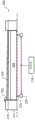
图3A示出了根据本公开的处于升高位置的示例性衬底支撑件;3A illustrates an exemplary substrate support in a raised position in accordance with the present disclosure;
图3B示出了根据本公开的布置在处于降低位置的衬底支撑件上的示例性测试晶片;3B illustrates an exemplary test wafer disposed on a substrate support in a lowered position in accordance with the present disclosure;
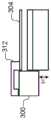
图3C示出了根据本公开的布置在处于降低位置的衬底支撑件上的另一示例性测试晶片;3C illustrates another exemplary test wafer disposed on a substrate support in a lowered position in accordance with the present disclosure;
图4A和4B是根据本公开的示例性测试晶片的平面图;4A and 4B are plan views of exemplary test wafers according to the present disclosure;
图5A和5B示出了根据本公开的具有第一几何形状的接触指;5A and 5B illustrate a contact finger having a first geometry according to the present disclosure;
图6A和6B示出了根据本公开的具有第二几何形状的接触指;6A and 6B illustrate a contact finger having a second geometry in accordance with the present disclosure;
图7A和7B示出了根据本公开的具有第三几何形状的接触指;以及7A and 7B illustrate a contact finger having a third geometry in accordance with the present disclosure; and
图8示出了根据本公开的用于测量边缘环的尺寸的示例性方法的步骤。8 illustrates steps of an exemplary method for measuring the dimensions of an edge ring in accordance with the present disclosure.
在附图中,附图标记可以重复使用以标识类似和/或相同的元件。In the drawings, reference numerals may be reused to identify similar and/or identical elements.
具体实施方式Detailed ways
衬底处理室中的衬底支撑件可以包括边缘环,边缘环用于将等离子体限制在衬底上方的体积,保护衬底支撑件免受由等离子体等引起的侵蚀。例如,边缘环可以被布置成控制衬底和边缘环附近及围绕衬底和边缘环的等离子体鞘的特性,以实现期望的临界尺寸均匀性(CDU)。边缘环的各种表面由于暴露于室内的等离子体而随着时间的推移经历磨损,导致边缘环的尺寸变化。因此,在室内处理的衬底的CDU可能受到影响。The substrate support in the substrate processing chamber may include an edge ring for confining the plasma to the volume above the substrate, protecting the substrate support from erosion caused by plasma and the like. For example, the edge rings may be arranged to control the properties of the plasma sheath near and around the substrate and edge rings to achieve a desired critical dimension uniformity (CDU). Various surfaces of the edge ring experience wear over time due to exposure to the plasma within the chamber, resulting in dimensional changes in the edge ring. Consequently, the CDU of substrates processed in-house may be affected.
因此,期望优选在不打开衬底处理室的情况下,周期性地测量受磨损影响的边缘环的尺寸,以确定是否更换或调整边缘环。用于测量边缘环的尺寸的示例性方法包括使用激光器和光电二极管,利用激光位移传感器等来测量布置在衬底支撑件上的衬底的倾斜。Accordingly, it is desirable to periodically measure the size of the edge ring affected by wear, preferably without opening the substrate processing chamber, to determine whether to replace or adjust the edge ring. Exemplary methods for measuring the dimensions of the edge ring include the use of lasers and photodiodes, the use of laser displacement sensors, and the like to measure the tilt of a substrate disposed on a substrate support.
根据本公开的原理的边缘环测量系统和方法实施可移动/可调节的边缘环(和/或可调节的衬底支撑件、卡盘、基座等)和测试晶片或仿真(dummy)晶片以测量边缘环的尺寸。可以使用例如用于独立地升高和降低边缘环的相应部分的一个或多个销以及相关联的致动器(例如,三个自由度或3DOF的平行机械手)来使边缘环可移动。测试晶片包括布置在测试晶片的边缘周围并从测试晶片的边缘向外延伸的一个或多个接触指。Edge ring measurement systems and methods in accordance with the principles of the present disclosure implement movable/adjustable edge rings (and/or adjustable substrate supports, chucks, susceptors, etc.) and test wafers or dummy wafers to Measure the size of the edge ring. The edge ring may be made movable using, for example, one or more pins and associated actuators (eg, three degrees of freedom or 3DOF parallel manipulators) for independently raising and lowering respective portions of the edge ring. The test wafer includes one or more contact fingers disposed around and extending outwardly from the edge of the test wafer.
测试晶片的有效直径(例如,由接触指的外端限定)大于边缘环的内径。因此,接触指接触边缘环的上表面。以这种方式,升高和降低边缘环相应地升高和降低测试晶片,并且可以独立地控制销以实现边缘环相对于测试晶片的期望定位(例如,高度、倾斜等)。在包括可调节的衬底支撑件的示例中,衬底支撑件可以被降低以使接触指以类似的方式接触边缘环。在测试晶片仅包括一个接触指的示例中,测试晶片可以被(例如,旋转地)定位,使得接触指与边缘环的期望部分对准。因此,升高边缘环以接合接触指将基于边缘环在该位置处的特性来使晶片有区别地地倾斜。The effective diameter of the test wafer (eg, as defined by the outer ends of the contact fingers) is greater than the inner diameter of the edge ring. Thus, the contact fingers contact the upper surface of the edge ring. In this manner, raising and lowering the edge ring correspondingly raises and lowers the test wafer, and the pins can be independently controlled to achieve the desired positioning (eg, height, tilt, etc.) of the edge ring relative to the test wafer. In examples that include an adjustable substrate support, the substrate support can be lowered so that the contact fingers contact the edge ring in a similar manner. In examples where the test wafer includes only one contact finger, the test wafer may be positioned (eg, rotationally) such that the contact finger is aligned with the desired portion of the edge ring. Thus, raising the edge ring to engage the contact fingers will tilt the wafer differently based on the properties of the edge ring at that location.
衬底处理室可以包括被定位成测量布置在衬底支撑件上的晶片的各种特性的测量装置(例如,光测量装置(例如光谱反射计或SR、激光光谱反射计或LSR等))。例如,SR可以直接位于衬底支撑件上方以在晶片处向下引导SR信号。光电二极管、电荷耦合器件(CCD)或其它感测装置被布置成感测从晶片的表面反射的SR信号。反射SR信号的特性指示晶片的各种特性。例如,反射SR信号可以指示晶片相对于衬底支撑件是否基本上平坦(即,平行于衬底支撑件的上表面)、是否倾斜等。因此,如果边缘环被升高,则一旦边缘环接合一个或多个接触指,反射SR信号的角度将改变。The substrate processing chamber may include measurement devices (eg, optical measurement devices (eg, spectroscopic reflectometer or SR, laser spectroscopic reflectometer or LSR, etc.)) positioned to measure various properties of the wafer disposed on the substrate support. For example, the SR can be located directly above the substrate support to direct the SR signal down at the wafer. A photodiode, charge coupled device (CCD) or other sensing device is arranged to sense the SR signal reflected from the surface of the wafer. The properties of the reflected SR signal are indicative of various properties of the wafer. For example, the reflected SR signal may indicate whether the wafer is substantially flat relative to the substrate support (ie, parallel to the upper surface of the substrate support), tilted, or the like. Therefore, if the edge ring is raised, the angle at which the SR signal is reflected will change once the edge ring engages one or more contact fingers.
相反,如果使用边缘环将晶片从衬底支撑件升高,则边缘环中的不均匀磨损将导致反射SR信号的角度与预期角度(即,对应于晶片在衬底支撑件上基本上平坦的角度)不同。类似地,如果使用边缘环(例如,通过仅致动一个销来倾斜边缘环)来有意地倾斜晶片,则反射SR信号将仍然指示晶片的倾斜是否对应于晶片的预期倾斜。Conversely, if an edge ring is used to lift the wafer from the substrate support, uneven wear in the edge ring will cause the angle of the reflected SR signal to be different from the expected angle (ie, corresponding to a substantially flat wafer on the substrate support). angle) are different. Similarly, if an edge ring is used to tilt the wafer intentionally (eg, tilting the edge ring by actuating only one pin), the reflected SR signal will still indicate whether the tilt of the wafer corresponds to the expected tilt of the wafer.
以这种方式,本文所述的系统和方法被配置为确定边缘环何时接合接触指,并且进一步确定边缘环的各个部分上的磨损。例如,接触指的相应几何形状(例如,接触表面轮廓)可以确定边缘环的哪个部分被测量。如果接触指被布置成接触边缘环的内径,则接触指和边缘环之间的接触可以指示边缘环的内径上的磨损。相反,如果接触指被布置成接触边缘环的中间直径或外径,则接触指和边缘环之间的接触可以指示边缘环的中间直径或外径上的磨损。虽然本文中描述为SR装置,但是本公开的原理可以使用被配置为感测边缘环何时接合测试晶片以及使测试晶片移动、倾斜等的任何测量装置来实现。In this manner, the systems and methods described herein are configured to determine when an edge ring engages a contact finger, and further to determine wear on various portions of the edge ring. For example, the corresponding geometry of the contact fingers (eg, contact surface profile) may determine which portion of the edge ring is measured. If the contact fingers are arranged to contact the inner diameter of the edge ring, the contact between the contact fingers and the edge ring may indicate wear on the inner diameter of the edge ring. Conversely, if the contact fingers are arranged to contact the middle or outer diameter of the edge ring, the contact between the contact fingers and the edge ring may indicate wear on the middle or outer diameter of the edge ring. Although described herein as an SR device, the principles of the present disclosure may be implemented using any measurement device configured to sense when the edge ring engages the test wafer and to move, tilt, etc. the test wafer.
现在参考图1,示出了根据本公开的用于蚀刻衬底的层(例如,仅钨或W层)的衬底处理室100的示例。尽管示出和描述了特定的衬底处理室,但是本文描述的方法可以在其他类型的衬底处理系统上实现。Referring now to FIG. 1 , there is shown an example of a
衬底处理室100包括下室区域102和上室区域104。下室区域102由室侧壁表面108、室底表面110和气体分配装置114的下表面限定。The
上室区域104由气体分配装置114的上表面和圆顶118的内表面限定。在一些示例中,圆顶118搁置在第一环形支撑件121上。在一些示例中,第一环形支撑件121包括用于将工艺气体输送到上室区域104的一个或多个间隔开的孔123,如下面将进一步描述的。在一些示例中,工艺气体通过一个或多个间隔开的孔123以相对于包括气体分配装置114的平面成锐角的向上方向输送,但也可以使用其它角度/方向。在一些示例中,第一环形支撑件121中的气体流动通道134向一个或多个间隔开的孔123供应气体。The
第一环形支撑件121可以搁置在第二环形支撑件125上,第二环形支撑件125限定用于将工艺气体从气体流动通道129输送到下室区域102的一个或多个间隔开的孔127。在一些示例中,气体分配装置114中的孔131与孔127对准。在其他示例中,气体分配装置114具有较小的直径,并且不需要孔131。在一些示例中,工艺气体通过一个或多个间隔开的孔127以相对于包括气体分配装置114的平面成锐角的朝向衬底的向下方向输送,但也可以使用其它角度/方向。The first
在其他示例中,上室区域104是具有平坦顶表面的圆筒形,并且可以使用一个或多个平坦的感应线圈。在其他示例中,单个室可以与位于喷头和衬底支撑件之间的间隔件(spacer)一起使用。In other examples, the
衬底支撑件122布置在下室区域102中。在一些示例中,衬底支撑件122包括静电卡盘(ESC),但是可以使用其他类型的衬底支撑件。在蚀刻期间,衬底126布置在衬底支撑件122的上表面上。在一些示例中,衬底126的温度可以由加热板132、具有流体通道的可选冷却板以及一个或多个传感器(未示出)来控制,但是可以使用任何其他合适的衬底支撑件温度控制系统。The
在一些示例中,气体分配装置114包括喷头(例如,具有多个间隔开的孔133的板128)。多个间隔开的孔133从板128的上表面延伸到板128的下表面。在一些示例中,间隔开的孔133具有在0.4”至0.75”范围内的直径,并且喷头由导电材料(诸如铝)或具有由导电材料制成的嵌入电极的非导电材料(诸如陶瓷)制造。In some examples, gas distribution device 114 includes a showerhead (eg,
一个或多个感应线圈140围绕圆顶118的外部部分布置。当通电时,一个或多个感应线圈140在圆顶118内部产生电磁场。在一些示例中,使用上线圈和下线圈。气体注射器142从气体输送系统150-1注射一种或多种气体混合物。One or
在一些示例中,气体输送系统150-1包括一个或多个气体源152、一个或多个阀154、一个或多个质量流量控制器(MFC)156、和混合歧管158,但是可以使用其它类型的气体输送系统。气体分流器(未示出)可以用于改变气体混合物的流速。(除了来自气体注射器142的蚀刻气体或者代替来自气体注射器142的蚀刻气体)可以使用另一气体输送系统150-2来向气体流动通道129和/或134供应蚀刻气体或蚀刻气体混合物。In some examples, the gas delivery system 150-1 includes one or
在于2015年12月4日提交的名称为“Gas Delivery System”的共同转让的美国专利申请序列No.14/945,680中示出并描述了合适的气体输送系统,其全部内容通过引用并入本文。在于2016年1月7日提交的名称为“Substrate Processing System with MultipleInjection Points and Dual Injector”的共同转让的美国临时专利申请序列No.62/275,837中示出和描述了合适的单气体注射器或双气体注射器和其它气体注射位置,其全部内容通过引用并入本文。A suitable gas delivery system is shown and described in commonly assigned US Patent Application Serial No. 14/945,680, filed December 4, 2015, entitled "Gas Delivery System," the entire contents of which are incorporated herein by reference. Suitable single gas injectors or dual gas injectors are shown and described in commonly assigned US Provisional Patent Application Serial No. 62/275,837, filed January 7, 2016, entitled "Substrate Processing System with Multiple Injection Points and Dual Injector" Syringes and other gas injection sites, the entire contents of which are incorporated herein by reference.
在一些示例中,气体注射器142包括沿向下方向引导气体的中心注射位置和以相对于向下方向成角度注射气体的一个或多个侧注射位置。在一些示例中,气体输送系统150-1将气体混合物的第一部分以第一流速输送到中心注射位置,以及将气体混合物的第二部分以第二流速输送到气体注射器142的侧注射位置。在其他示例中,由气体注射器142输送不同的气体混合物。在一些示例中,气体输送系统150-1将调谐气体输送到气体流动通道129和134和/或输送到处理室中的其它位置,如在下面将描述的。In some examples, gas injector 142 includes a central injection location that directs gas in a downward direction and one or more side injection locations that inject gas at an angle relative to the downward direction. In some examples, the gas delivery system 150-1 delivers a first portion of the gas mixture to the central injection location at a first flow rate and a second portion of the gas mixture to the side injection locations of the gas injector 142 at a second flow rate. In other examples, different gas mixtures are delivered by gas injector 142 . In some examples, gas delivery system 150-1 delivers tuning gas to
等离子体发生器170可以用于产生输出到一个或多个感应线圈140的RF功率。等离子体190在上室区域104中产生。在一些示例中,等离子体发生器170包括RF发生器172和匹配网络174。匹配网络174将RF发生器172的阻抗与一个或多个感应线圈140的阻抗匹配。在一些示例中,气体分配装置114连接到诸如地的参考电位。阀178和泵180可以用于控制下室区域102和上室区域104内部的压力并且用于抽空反应物。
控制器176与气体输送系统150-1和150-2、阀178、泵180和/或等离子体发生器170连通,以控制工艺气体的流动、吹扫气体、RF等离子体和室压力。在一些示例中,通过一个或多个感应线圈140在圆顶118内维持等离子体。使用气体注射器142(和/或孔123)从室的顶部引入一种或多种气体混合物,并且使用气体分配装置114将等离子体限制在圆顶118内。
将等离子体限制在圆顶118内允许等离子体物质和通过气体分配装置114流出的所需蚀刻剂物质的体积复合。在一些示例中,没有RF偏置施加到衬底126。结果,在衬底126上不存在活性鞘,并且离子不以任何有限的能量撞击衬底。某些数量的离子将通过气体分配装置114扩散出等离子体区域。然而,扩散的等离子体的量的数量级比位于圆顶118内部的等离子体低。等离子体中的大多数离子在高压下通过体积复合而损失。气体分配装置114的上表面处的表面复合损失也降低气体分配装置114下方的离子密度。Confining the plasma within the
在其他示例中,提供RF偏置发生器184,并且RF偏置发生器184包括RF发生器186和匹配网络188。RF偏置可以用于在气体分配装置114和衬底支撑件之间产生等离子体,或者在衬底126上产生自偏置以吸引离子。控制器176可以用于控制RF偏置。In other examples,
衬底支撑件122包括边缘环192。根据本公开的原理的边缘环192可相对于衬底126移动(例如,在垂直方向上可向上和向下移动),和/或衬底支撑件122可向上和向下移动。例如,边缘环192和/或衬底支撑件122可以经由响应于控制器176的一个或多个致动器来控制,如在下面更详细地描述的。The
衬底126包括定位成接合边缘环192的一个或多个接触指194。例如,升高和降低边缘环192和/或衬底支撑件122选择性地使边缘环192接合接触指194,如下面更详细地描述的。SR装置196布置成在衬底126的表面处引导SR信号。SR信号由传感器(例如,光电二极管)198反射和接收。在边缘环192与接触指194接触(例如,如由反射SR信号所指示的)时,可以使用边缘环192(和/或衬底支撑件122)的高度来计算(例如,如受磨损影响的)边缘环192的尺寸。The
现在参考图2A、2B和2C,示出了根据本公开的原理的其上布置有相应的测试衬底或晶片204的示例性衬底支撑件200。衬底支撑件200可以各自包括具有内部部分(例如,对应于ESC)208和外部部分212的基座或底座。在示例中,内部部分208可以独立于外部部分212并且可相对于外部部分212移动(即,在内部部分208被构造成被升高和/或降低的示例中)。控制器216与一个或多个致动器220连通,以选择性地升高和降低边缘环224。仅作为示例,边缘环224示出为处于图2A中的完全降低的位置以及处于图2B和2C中的示例性升高的位置。如示例中所示,致动器220对应于被构造成在垂直方向上选择性地延伸和缩回销228的销致动器。在其他示例中可以使用其他合适类型的致动器。例如,致动器220可以对应于被构造成接合相应销228的螺纹的马达,从而以逐步方式升高和降低销228。仅作为示例,边缘环224对应于陶瓷或石英边缘环。Referring now to FIGS. 2A, 2B, and 2C, an
测试晶片204包括一个或多个接触指232。尽管示出了两个接触指232,但是在示例中,测试晶片204可以包括一个、两个、三个或三个以上接触指232。在图2B中,控制器216被示出与致动器220连通以升高整个边缘环224。例如,控制器216、致动器220和销228可以被配置为使得仅整个边缘环224被升高和降低,或者控制器216可以被配置为单独地控制销228。因此,测试晶片204相对于衬底支撑件200是基本上平坦的(即,平行于衬底支撑件200)。相反,在图2C中,控制器216被示出仅与致动器220中的一个连通以升高销228中的相应一个并且仅升高边缘环224的一部分。因此,测试晶片204相对于衬底支撑件200倾斜。
在衬底支撑件200仅包括致动器220中的一个和相应的销228的示例中,测试晶片204可以旋转并布置在不同位置,以使接触指232与边缘环224的不同部分对准。以这种方式,当边缘环224接合接触指232时,边缘环224的高度指示边缘环224的与接触指232对准的部分的尺寸(例如,磨损)。In the example where the
在如图3A、3B和3C所示的另一个示例中,边缘环224(和/或边缘环224安装在其上的外部部分212)的绝对高度相对于室底表面可以是固定的。相反,内部部分208(例如,ESC)可相对于边缘环224移动。因此,控制器216可与致动器220连通以相对于边缘环224升高和降低内部部分208,以调节边缘环224相对于衬底支撑件200的高度。内部部分208被示出为处于图3A中的升高位置,以及处于图3B和3C中的示例性降低位置。因此,在测试晶片204包括多个接触指232(例如,如图3B所示)的示例中,整个测试晶片204由边缘环224支撑,并且相对于衬底支撑件200基本上是平坦的(即,平行于衬底支撑件200)。相反,在测试晶片204仅包括接触指232中的一个(例如,如图3C所示)的示例中,边缘环224支撑对应于接触指232的测试晶片204的一部分,并且测试晶片204相对于衬底支撑件200倾斜。测试晶片204可以旋转并布置在不同位置,以使接触指232与边缘环224的不同部分对准。In another example as shown in Figures 3A, 3B and 3C, the absolute height of edge ring 224 (and/or
在上述示例中,边缘环224和内部部分208的相应升高和降低的高度(以及测试晶片204相对于衬底支撑件200的相应取向或倾斜)仅出于说明的目的而示出。在操作中,可以仅升高边缘环224,直到边缘环224接合接触指232中的一个或多个,从而改变反射SR信号的特性。类似地,可以仅降低内部部分208,直到接触指232中的一个或多个接合边缘环224,从而改变反射SR信号的特性。In the above examples, the corresponding raised and lowered heights of
以这种方式,控制器216被配置成:监测反射SR信号的特性以检测边缘环224何时接合接触指232(反之亦然),确定边缘环224与接触指232接合处的边缘环224(和/或内部部分208)的第一高度,确定第一高度和对应于新的(即未磨损的、最理想的等)边缘环的高度之间的差值,以及基于该差值来计算边缘环224的尺寸。因此,当边缘环224随着时间推移而磨损时,可以计算边缘环224的上表面中的变化,并且可以定位边缘环224(和/或内部部分208)以补偿磨损。例如,如果控制器216计算出边缘环224的内径的厚度减小了0.X毫米(例如,平均围绕边缘环224的圆周),则在衬底的处理期间,控制器216可以将边缘环224升高0.X毫米。此外,控制器216可以确定(并且经由LED、图形界面等向用户指示)边缘环224何时需要维护、更换等。当用户等提示时,控制器216可以周期性地通过上述方法执行边缘环224尺寸的测量。In this manner, the
图4A和4B示出了示例测试晶片260和264的平面图。在图4A中,测试晶片260包括多个(例如三个)接触指268。在图4B中,测试晶片264仅包括接触指268中的一个。接触指268中的一个或多个可以包括凹口272。凹口272可以用于相对于衬底支撑件以期望的对准来定位测试晶片260和264。例如,可以通过检测凹口272(例如,使用照相机或其它图像感测装置)以及相应地计算测试晶片260和264的对准来确定测试晶片260和264的位置。4A and 4B illustrate plan views of
图5A和5B、6A和6B以及7A和7B示出了示例性边缘环300和测试晶片304。图5A、6A和7A示出了在边缘环300经历磨损之前的边缘环300的高度H。图5B、6B和7B示出了高度H加上偏移量d以补偿边缘环300的相应磨损。例如,H+d对应于当(例如,使用控制器216和反射SR信号)确定边缘环300接合接触指308、312和316时边缘环300的相应高度。接触指308、312和316具有用于测量边缘环300的尺寸的不同几何形状(即,接触表面轮廓)。在图5A和5B中,接触指308被配置为接合边缘环300的内径。如图5B所示,随着边缘环300的内径随时间推移而磨损,边缘环300在不同的高度接合接触指308。因此,边缘环300可以被升高以确定对边缘环300的内径的磨损量(以及尺寸的相应变化),以及实现边缘环的上表面和正被处理的晶片之间的期望关系。相反,接触指312被配置为接合边缘环300的外径,以及接触指316被配置为接合边缘环300的中间直径。以这种方式,可以测量边缘环300的不同部分的尺寸。5A and 5B, 6A and 6B, and 7A and 7B illustrate an
现在参考图8,根据本公开的用于测量边缘环的尺寸的示例性方法400在404开始。在408,将测试衬底布置在衬底支撑件上。例如,测试衬底包括如上相对于图1-7所述的接触指,并且接触指在衬底支撑件的边缘环上方延伸。在412,边缘环被升高(或者,在一些示例中,衬底支撑件的内部部分被降低)。在416,方法400(例如,控制器216)确定边缘环(例如,边缘环的内径)是否接合接触指。例如,控制器216基于从测试衬底的表面反射的信号来确定边缘环是否接合接触指。如果为真,则方法400继续到420。如果为假,则方法400继续到412。Referring now to FIG. 8 , an exemplary method 400 for measuring the dimensions of an edge ring in accordance with the present disclosure begins at 404 . At 408, the test substrate is placed on the substrate support. For example, the test substrate includes contact fingers as described above with respect to Figures 1-7, and the contact fingers extend over the edge ring of the substrate support. At 412, the edge ring is raised (or, in some examples, the inner portion of the substrate support is lowered). At 416 , method 400 (eg, controller 216 ) determines whether the edge ring (eg, the inner diameter of the edge ring) engages the contact finger. For example, the
在420,方法400(例如,控制器216)基于边缘环何时接合接触指来确定衬底处理系统的至少一个特性。例如,控制器216基于在边缘环接合接触指时边缘环(或在内部部分被降低的示例中的衬底支撑件的内部部分)的位置/高度、边缘环被升高的总量等来计算边缘环的磨损。方法400在424结束。At 420, method 400 (eg, controller 216) determines at least one characteristic of the substrate processing system based on when the edge ring engages the contact fingers. For example, the
前面的描述本质上仅仅是说明性的,并且绝不旨在限制本公开、其应用或用途。本公开的广泛教导可以以各种形式实现。因此,虽然本公开包括特定示例,但是本公开的真实范围不应当被如此限制,因为在研究附图、说明书和所附权利要求时,其他修改将变得显而易见。应当理解,在不改变本公开的原理的情况下,方法中的一个或多个步骤可以以不同的顺序(或同时地)执行。此外,虽然每个实施方式在上面被描述为具有某些特征,但是相对于本公开的任何实施方式描述的那些特征中的任何一个或多个,可以在任何其它实施方式的特征中实现和/或与任何其它实施方式的特征组合,即使该组合没有明确描述。换句话说,所描述的实施方式不是相互排斥的,并且一个或多个实施方式彼此的置换保持在本公开的范围内。The foregoing description is merely illustrative in nature and is in no way intended to limit the present disclosure, its application, or uses. The broad teachings of the present disclosure can be implemented in a variety of forms. Thus, although this disclosure includes specific examples, the true scope of the disclosure should not be so limited, as other modifications will become apparent upon study of the drawings, specification, and appended claims. It should be understood that one or more steps within a method may be executed in different order (or concurrently) without altering the principles of the present disclosure. Additionally, although each embodiment is described above as having certain features, any one or more of those features described with respect to any embodiment of the present disclosure may be implemented and/or implemented in the features of any other embodiment. or in combination with features of any other embodiment, even if the combination is not explicitly described. In other words, the described embodiments are not mutually exclusive, and substitutions of one or more embodiments for each other remain within the scope of the present disclosure.
使用各种术语来描述元件之间(例如,模块之间、电路元件之间、半导体层之间等)的空间和功能关系,各种术语包括“连接”、“接合”、“耦合”、“相邻”、“紧挨”、“在...顶部”、“在...上面”、“在...下面”和“设置”。除非将第一和第二元件之间的关系明确地描述为“直接”,否则在上述公开中描述这种关系时,该关系可以是直接关系,其中在第一和第二元件之间不存在其它中间元件,但是也可以是间接关系,其中在第一和第二元件之间(在空间上或功能上)存在一个或多个中间元件。如本文所使用的,短语“A、B和C中的至少一个”应当被解释为意味着使用非排他性逻辑或(OR)的逻辑(A或B或C),并且不应被解释为表示“A中的至少一个、B中的至少一个和C中的至少一个”。Various terms are used to describe the spatial and functional relationships between elements (eg, between modules, between circuit elements, between semiconductor layers, etc.), including "connected", "bonded", "coupled", " Adjacent, Immediately, On Top, Above, Below, and Set. Unless a relationship between a first and second element is expressly described as "direct", when such a relationship is described in the above disclosure, the relationship may be a direct relationship in which no relationship exists between the first and second elements Other intervening elements, but also an indirect relationship, wherein one or more intervening elements are present (spatially or functionally) between the first and second elements. As used herein, the phrase "at least one of A, B, and C" should be interpreted to mean a logical (A or B or C) using a non-exclusive logical OR (OR), and should not be interpreted to mean " At least one of A, at least one of B and at least one of C".
在一些实现方式中,控制器是系统的一部分,该系统可以是上述示例的一部分。这样的系统可以包括半导体处理设备,半导体处理设备包括一个或多个处理工具、一个或多个室、用于处理的一个或多个平台、和/或特定处理部件(晶片基座、气体流系统等)。这些系统可以与用于在半导体晶片或衬底的处理之前、期间和之后控制它们的操作的电子器件集成。电子器件可以被称为“控制器”,其可以控制一个或多个系统的各种部件或子部件。根据处理要求和/或系统类型,控制器可以被编程以控制本文公开的任何工艺,包括处理气体的输送、温度设置(例如加热和/或冷却)、压力设置、真空设置、功率设置、射频(RF)发生器设置、RF匹配电路设置、频率设置、流率设置、流体输送设置、位置和操作设置、进出工具和其他输送工具和/或连接到特定系统或与特定系统接口的装载锁的晶片输送。In some implementations, the controller is part of a system, which may be part of the above examples. Such systems may include semiconductor processing equipment including one or more processing tools, one or more chambers, one or more platforms for processing, and/or specific processing components (wafer susceptors, gas flow systems Wait). These systems can be integrated with electronics for controlling the operation of semiconductor wafers or substrates before, during, and after their processing. Electronic devices may be referred to as "controllers," which may control various components or sub-components of one or more systems. Depending on process requirements and/or system type, the controller can be programmed to control any of the processes disclosed herein, including the delivery of process gases, temperature settings (eg, heating and/or cooling), pressure settings, vacuum settings, power settings, radio frequency ( RF) generator settings, RF matching circuit settings, frequency settings, flow rate settings, fluid delivery settings, location and operation settings, access to tools and other delivery tools and/or wafers connected to or interfaced with a specific system of load locks delivery.
概括地说,控制器可以定义为电子器件,电子器件具有接收指令、发出指令、控制操作、启用清洁操作、启用终点测量等的各种集成电路、逻辑、存储器和/或软件。集成电路可以包括存储程序指令的固件形式的芯片、数字信号处理器(DSP)、定义为专用集成电路(ASIC)的芯片、和/或一个或多个微处理器、或执行程序指令(例如,软件)的微控制器。程序指令可以是以各种单独设置(或程序文件)的形式输送到控制器的指令,单独设置(或程序文件)定义用于在半导体晶片上或针对半导体晶片或系统执行特定工艺的操作参数。在一些实施方式中,操作参数可以是由工艺工程师定义的配方的一部分,以在一或多个(种)层、材料、金属、氧化物、硅、二氧化硅、表面、电路和/或晶片的管芯的制造期间完成一个或多个处理步骤。In general terms, a controller may be defined as an electronic device having various integrated circuits, logic, memory, and/or software that receive instructions, issue instructions, control operations, enable cleaning operations, enable endpoint measurements, and the like. An integrated circuit may include a chip in the form of firmware that stores program instructions, a digital signal processor (DSP), a chip defined as an application specific integrated circuit (ASIC), and/or one or more microprocessors, or execute program instructions (eg, software) microcontroller. Program instructions may be instructions delivered to the controller in the form of various individual settings (or program files) that define operating parameters for performing particular processes on or for a semiconductor wafer or system. In some embodiments, the operating parameters may be part of a recipe defined by a process engineer for one or more layer(s), materials, metals, oxides, silicon, silicon dioxide, surfaces, circuits and/or wafers One or more processing steps are completed during the fabrication of the die.
在一些实现方式中,控制器可以是与系统集成、耦合到系统、以其它方式联网到系统或其组合的计算机的一部分或耦合到该计算机。例如,控制器可以在“云”中或在晶片厂(fab)主机系统的全部或一部分中,其可以允许对晶片处理的远程访问。计算机可以实现对系统的远程访问以监视制造操作的当前进展、检查过去制造操作的历史、从多个制造操作研究趋势或性能度量,以改变当前处理的参数、设置要跟随当前处理的处理步骤、或者开始新的处理。在一些示例中,远程计算机(例如服务器)可以通过网络(其可以包括本地网络或因特网)向系统提供工艺配方。远程计算机可以包括使得能够输入或编程参数和/或设置的用户接口,然后将该参数和/或设置从远程计算机输送到系统。在一些示例中,控制器接收数据形式的指令,其指定在一个或多个操作期间要执行的每个处理步骤的参数。应当理解,参数可以特定于要执行的工艺的类型和工具的类型,控制器被配置为与该工具接口或控制该工具。因此,如上所述,控制器可以是例如通过包括联网在一起并朝着共同目的(例如本文所述的工艺和控制)工作的一个或多个离散控制器而呈分布式。用于这种目的的分布式控制器的示例是在与远程(例如在平台级或作为远程计算机的一部分)定位的一个或多个集成电路通信的室上的一个或多个集成电路,其组合以控制在室上的工艺。In some implementations, the controller may be part of or coupled to a computer integrated with the system, coupled to the system, otherwise networked to the system, or a combination thereof. For example, the controller may be in the "cloud" or in all or part of a fab host system, which may allow remote access to wafer processing. The computer can enable remote access to the system to monitor the current progress of manufacturing operations, examine the history of past manufacturing operations, study trends or performance metrics from multiple manufacturing operations to change the parameters of the current process, set process steps to follow the current process, Or start a new process. In some examples, a remote computer (eg, a server) may provide process recipes to the system over a network (which may include a local network or the Internet). The remote computer may include a user interface that enables parameters and/or settings to be entered or programmed, which are then transferred from the remote computer to the system. In some examples, the controller receives instructions in the form of data specifying parameters for each processing step to be performed during one or more operations. It should be understood that the parameters may be specific to the type of process to be performed and the type of tool with which the controller is configured to interface or control. Thus, as described above, the controllers may be distributed, for example, by including one or more discrete controllers networked together and working toward a common purpose, such as the processes and controls described herein. An example of a distributed controller for this purpose is one or more integrated circuits on a room in communication with one or more integrated circuits located remotely (eg, at the platform level or as part of a remote computer), combinations of these to control the process on the chamber.
示例系统可以包括但不限于等离子体蚀刻室或模块、沉积室或模块、旋转漂洗室或模块、金属电镀室或模块、清洁室或模块、倒角边缘蚀刻室或模块、物理气相沉积(PVD)室或模块、化学气相沉积(CVD)室或模块、原子层沉积(ALD)室或模块、原子层蚀刻(ALE)室或模块、离子注入室或模块、轨道室或模块、以及可以与半导体晶片的制造和/或制备相关联或用于半导体晶片的制造和/或制备的任何其它半导体处理系统。Example systems may include, but are not limited to, plasma etch chambers or modules, deposition chambers or modules, spin-rinse chambers or modules, metal plating chambers or modules, clean chambers or modules, bevel edge etch chambers or modules, physical vapor deposition (PVD) chambers or modules, chemical vapor deposition (CVD) chambers or modules, atomic layer deposition (ALD) chambers or modules, atomic layer etching (ALE) chambers or modules, ion implantation chambers or modules, orbital chambers or modules, and can interact with semiconductor wafers Any other semiconductor processing system associated with or used in the fabrication and/or preparation of semiconductor wafers.
如上所述,根据将由工具执行的一个或多个处理步骤,控制器可以与一个或多个其他工具电路或模块、其它工具部件、群集工具、其他工具接口、相邻工具、邻近工具、位于整个工厂中的工具、主计算机、另一控制器、或在将晶片容器往返半导体制造工厂中的工具位置和/或装载口运输的材料运输中使用的工具通信。As described above, the controller may interface with one or more other tool circuits or modules, other tool components, clustered tools, other tooling, adjacent tools, adjacent tools, located throughout A tool in the fab communicates with a host computer, another controller, or a tool used in material transport to transport wafer containers to and from tool locations and/or load ports in a semiconductor fabrication fab.
Claims (15)
Priority Applications (1)
| Application Number | Priority Date | Filing Date | Title |
|---|---|---|---|
| CN201910856579.4ACN110767525B (en) | 2016-03-29 | 2017-01-17 | System and method for determining edge ring characteristics |
Applications Claiming Priority (4)
| Application Number | Priority Date | Filing Date | Title |
|---|---|---|---|
| US201662314659P | 2016-03-29 | 2016-03-29 | |
| US62/314,659 | 2016-03-29 | ||
| US15/403,786 | 2017-01-11 | ||
| US15/403,786US11011353B2 (en) | 2016-03-29 | 2017-01-11 | Systems and methods for performing edge ring characterization |
Related Child Applications (1)
| Application Number | Title | Priority Date | Filing Date |
|---|---|---|---|
| CN201910856579.4ADivisionCN110767525B (en) | 2016-03-29 | 2017-01-17 | System and method for determining edge ring characteristics |
Publications (2)
| Publication Number | Publication Date |
|---|---|
| CN107240541A CN107240541A (en) | 2017-10-10 |
| CN107240541Btrue CN107240541B (en) | 2019-10-15 |
Family
ID=59959706
Family Applications (2)
| Application Number | Title | Priority Date | Filing Date |
|---|---|---|---|
| CN201710036188.9AActiveCN107240541B (en) | 2016-03-29 | 2017-01-17 | System and method for performing edge ring characterization |
| CN201910856579.4AActiveCN110767525B (en) | 2016-03-29 | 2017-01-17 | System and method for determining edge ring characteristics |
Family Applications After (1)
| Application Number | Title | Priority Date | Filing Date |
|---|---|---|---|
| CN201910856579.4AActiveCN110767525B (en) | 2016-03-29 | 2017-01-17 | System and method for determining edge ring characteristics |
Country Status (5)
| Country | Link |
|---|---|
| US (1) | US11011353B2 (en) |
| JP (1) | JP6976686B2 (en) |
| KR (1) | KR20170113014A (en) |
| CN (2) | CN107240541B (en) |
| TW (1) | TWI774652B (en) |
Families Citing this family (51)
| Publication number | Priority date | Publication date | Assignee | Title |
|---|---|---|---|---|
| US10658222B2 (en) | 2015-01-16 | 2020-05-19 | Lam Research Corporation | Moveable edge coupling ring for edge process control during semiconductor wafer processing |
| US10957561B2 (en) | 2015-07-30 | 2021-03-23 | Lam Research Corporation | Gas delivery system |
| US10825659B2 (en) | 2016-01-07 | 2020-11-03 | Lam Research Corporation | Substrate processing chamber including multiple gas injection points and dual injector |
| CN116110846A (en) | 2016-01-26 | 2023-05-12 | 应用材料公司 | Wafer edge ring lift solution |
| CN108369922B (en) | 2016-01-26 | 2023-03-21 | 应用材料公司 | Wafer edge ring lifting solution |
| US10651015B2 (en) | 2016-02-12 | 2020-05-12 | Lam Research Corporation | Variable depth edge ring for etch uniformity control |
| US10699878B2 (en) | 2016-02-12 | 2020-06-30 | Lam Research Corporation | Chamber member of a plasma source and pedestal with radially outward positioned lift pins for translation of a substrate c-ring |
| US10410832B2 (en) | 2016-08-19 | 2019-09-10 | Lam Research Corporation | Control of on-wafer CD uniformity with movable edge ring and gas injection adjustment |
| US9947517B1 (en) | 2016-12-16 | 2018-04-17 | Applied Materials, Inc. | Adjustable extended electrode for edge uniformity control |
| US10553404B2 (en) | 2017-02-01 | 2020-02-04 | Applied Materials, Inc. | Adjustable extended electrode for edge uniformity control |
| US11075105B2 (en) | 2017-09-21 | 2021-07-27 | Applied Materials, Inc. | In-situ apparatus for semiconductor process module |
| JP6966286B2 (en)* | 2017-10-11 | 2021-11-10 | 東京エレクトロン株式会社 | Plasma processing device, focus ring elevation control method and focus ring elevation control program |
| CN118380371A (en) | 2017-11-21 | 2024-07-23 | 朗姆研究公司 | Bottom edge ring and middle edge ring |
| CN109841536A (en)* | 2017-11-29 | 2019-06-04 | 长鑫存储技术有限公司 | Edge compensation system, wafer carrier system and wafer installation method |
| US11043400B2 (en) | 2017-12-21 | 2021-06-22 | Applied Materials, Inc. | Movable and removable process kit |
| JP7037964B2 (en)* | 2018-03-09 | 2022-03-17 | 東京エレクトロン株式会社 | How the system operates to inspect the measuring instrument and focus ring |
| US10600623B2 (en) | 2018-05-28 | 2020-03-24 | Applied Materials, Inc. | Process kit with adjustable tuning ring for edge uniformity control |
| US10957521B2 (en)* | 2018-05-29 | 2021-03-23 | Lam Research Corporation | Image based plasma sheath profile detection on plasma processing tools |
| US11935773B2 (en) | 2018-06-14 | 2024-03-19 | Applied Materials, Inc. | Calibration jig and calibration method |
| KR102433436B1 (en) | 2018-07-04 | 2022-08-17 | 삼성전자주식회사 | Substrate processing system, edge rign inspection method in the substrate processing system, and disk-type vision sensor performing for the same |
| KR20210111872A (en)* | 2018-08-13 | 2021-09-13 | 램 리써치 코포레이션 | Replaceable and/or collapsible edge ring assemblies for plasma sheath tuning incorporating edge ring positioning and centering features |
| JP7076351B2 (en)* | 2018-10-03 | 2022-05-27 | 東京エレクトロン株式会社 | Plasma processing device and ring member thickness measurement method |
| JP2020087969A (en)* | 2018-11-15 | 2020-06-04 | 東京エレクトロン株式会社 | Plasma processing apparatus, and method of measuring shape of ring member |
| US11289310B2 (en) | 2018-11-21 | 2022-03-29 | Applied Materials, Inc. | Circuits for edge ring control in shaped DC pulsed plasma process device |
| US11512393B2 (en)* | 2018-11-29 | 2022-11-29 | Lam Research Corporation | Dynamic sheath control with edge ring lift |
| JP2020115499A (en)* | 2019-01-17 | 2020-07-30 | 東京エレクトロン株式会社 | Plasma processing apparatus and ring member position deviation measuring method |
| CN113785387B (en)* | 2019-03-04 | 2025-05-09 | 朗姆研究公司 | Apparatus for automatic calibration of substrate transfer robots |
| WO2020180656A1 (en)* | 2019-03-06 | 2020-09-10 | Lam Research Corporation | Measurement system to measure a thickness of an adjustable edge ring for a substrate processing system |
| US11279032B2 (en) | 2019-04-11 | 2022-03-22 | Applied Materials, Inc. | Apparatus, systems, and methods for improved joint coordinate teaching accuracy of robots |
| US11101115B2 (en) | 2019-04-19 | 2021-08-24 | Applied Materials, Inc. | Ring removal from processing chamber |
| US12009236B2 (en) | 2019-04-22 | 2024-06-11 | Applied Materials, Inc. | Sensors and system for in-situ edge ring erosion monitor |
| US10964584B2 (en) | 2019-05-20 | 2021-03-30 | Applied Materials, Inc. | Process kit ring adaptor |
| US12165905B2 (en) | 2019-05-20 | 2024-12-10 | Applied Materials, Inc. | Process kit enclosure system |
| US11913777B2 (en)* | 2019-06-11 | 2024-02-27 | Applied Materials, Inc. | Detector for process kit ring wear |
| US11626305B2 (en) | 2019-06-25 | 2023-04-11 | Applied Materials, Inc. | Sensor-based correction of robot-held object |
| KR102689653B1 (en) | 2019-06-26 | 2024-07-31 | 삼성전자주식회사 | Sensor module and etching apparatus having the same |
| CN112216646A (en)* | 2019-07-10 | 2021-01-12 | Asm Ip私人控股有限公司 | Substrate supporting assembly and substrate processing device comprising same |
| US11211269B2 (en) | 2019-07-19 | 2021-12-28 | Applied Materials, Inc. | Multi-object capable loadlock system |
| CN112701027B (en)* | 2019-10-22 | 2024-09-17 | 夏泰鑫半导体(青岛)有限公司 | Plasma processing device and edge ring replacement method |
| US11370114B2 (en) | 2019-12-09 | 2022-06-28 | Applied Materials, Inc. | Autoteach enclosure system |
| JP7263225B2 (en)* | 2019-12-12 | 2023-04-24 | 東京エレクトロン株式会社 | Conveying system and method |
| WO2021126696A1 (en)* | 2019-12-19 | 2021-06-24 | Lam Research Corporation | Encapsulated rfid in consumable chamber parts |
| KR102822822B1 (en)* | 2020-02-25 | 2025-06-19 | 에스케이하이닉스 주식회사 | Monitoring device of edge ring, system for managing edge ring and method for managing edge ring |
| CN111341698B (en)* | 2020-03-09 | 2022-07-26 | 苏州能讯高能半导体有限公司 | Etching equipment |
| US12027397B2 (en) | 2020-03-23 | 2024-07-02 | Applied Materials, Inc | Enclosure system shelf including alignment features |
| USD980176S1 (en) | 2020-06-02 | 2023-03-07 | Applied Materials, Inc. | Substrate processing system carrier |
| USD954769S1 (en) | 2020-06-02 | 2022-06-14 | Applied Materials, Inc. | Enclosure system shelf |
| US12159795B2 (en) | 2021-03-08 | 2024-12-03 | Applied Materials, Inc. | Enclosure system having walls comprising sidewalls and radio-frequency identifier holder coupled to rear wall |
| US20240429089A1 (en)* | 2023-06-21 | 2024-12-26 | Applied Materials, Inc. | Adjustable edge ring tilt for edge of wafer skew compensation |
| WO2025122347A1 (en)* | 2023-12-04 | 2025-06-12 | Lam Research Corporation | Azimuthal edge ring control to improve residual non-uniformity near substrate edges |
| US20250246415A1 (en)* | 2024-01-30 | 2025-07-31 | Applied Materials, Inc. | Extreme edge sheath tunability with non-movable edge ring |
Citations (9)
| Publication number | Priority date | Publication date | Assignee | Title |
|---|---|---|---|---|
| KR20050008792A (en)* | 2002-06-03 | 2005-01-21 | 어플라이드 머티어리얼스, 인코포레이티드 | A cathode pedestal for a plasma etch reactor |
| KR20080023569A (en)* | 2006-09-11 | 2008-03-14 | 주식회사 하이닉스반도체 | Plasma Etching Device to Prevent Etch Profile Deformation |
| CN102243977A (en)* | 2010-05-12 | 2011-11-16 | 东京毅力科创株式会社 | Plasma processing apparatus and method of manufacturing semiconductor device |
| CN102315150A (en)* | 2010-06-30 | 2012-01-11 | 朗姆研究公司 | The removable basic ring that is used for plasma processing chamber |
| CN103730318A (en)* | 2013-11-15 | 2014-04-16 | 中微半导体设备(上海)有限公司 | Wafer edge protection ring and method for reducing particles at wafer edge |
| CN104299929A (en)* | 2013-07-19 | 2015-01-21 | 朗姆研究公司 | Systems and methods for in-situ wafer edge and backside plasma cleaning |
| CN104752141A (en)* | 2013-12-31 | 2015-07-01 | 中微半导体设备(上海)有限公司 | Plasma processing device and operating method thereof |
| CN104851832A (en)* | 2014-02-18 | 2015-08-19 | 北京北方微电子基地设备工艺研究中心有限责任公司 | Fixing device, reaction cavity and plasma processing device |
| CN105336561A (en)* | 2014-07-18 | 2016-02-17 | 中微半导体设备(上海)有限公司 | Plasma etching device |
Family Cites Families (43)
| Publication number | Priority date | Publication date | Assignee | Title |
|---|---|---|---|---|
| JP2638443B2 (en) | 1993-08-31 | 1997-08-06 | 日本電気株式会社 | Dry etching method and dry etching apparatus |
| US5762714A (en) | 1994-10-18 | 1998-06-09 | Applied Materials, Inc. | Plasma guard for chamber equipped with electrostatic chuck |
| JP2713276B2 (en) | 1995-12-07 | 1998-02-16 | 日本電気株式会社 | Semiconductor device manufacturing apparatus and semiconductor device manufacturing method using the same |
| US6075606A (en) | 1996-02-16 | 2000-06-13 | Doan; Trung T. | Endpoint detector and method for measuring a change in wafer thickness in chemical-mechanical polishing of semiconductor wafers and other microelectronic substrates |
| US6022809A (en) | 1998-12-03 | 2000-02-08 | Taiwan Semiconductor Manufacturing Company, Ltd. | Composite shadow ring for an etch chamber and method of using |
| US6206976B1 (en)* | 1999-08-27 | 2001-03-27 | Lucent Technologies Inc. | Deposition apparatus and related method with controllable edge exclusion |
| US6589352B1 (en) | 1999-12-10 | 2003-07-08 | Applied Materials, Inc. | Self aligning non contact shadow ring process kit |
| JP2001230239A (en)* | 2000-02-15 | 2001-08-24 | Tokyo Electron Ltd | Apparatus and method for treating |
| TW506234B (en) | 2000-09-18 | 2002-10-11 | Tokyo Electron Ltd | Tunable focus ring for plasma processing |
| JP3388228B2 (en)* | 2000-12-07 | 2003-03-17 | 株式会社半導体先端テクノロジーズ | Plasma etching apparatus and plasma etching method |
| US6744212B2 (en) | 2002-02-14 | 2004-06-01 | Lam Research Corporation | Plasma processing apparatus and method for confining an RF plasma under very high gas flow and RF power density conditions |
| US6938505B2 (en)* | 2002-08-13 | 2005-09-06 | Taiwan Semiconductor Manufacturing Co., Ltd. | Chamber wafer detection |
| US6896765B2 (en) | 2002-09-18 | 2005-05-24 | Lam Research Corporation | Method and apparatus for the compensation of edge ring wear in a plasma processing chamber |
| US7311784B2 (en) | 2002-11-26 | 2007-12-25 | Tokyo Electron Limited | Plasma processing device |
| US6898558B2 (en) | 2002-12-31 | 2005-05-24 | Tokyo Electron Limited | Method and apparatus for monitoring a material processing system |
| US7064812B2 (en) | 2003-08-19 | 2006-06-20 | Tokyo Electron Limited | Method of using a sensor gas to determine erosion level of consumable system components |
| JP2006173223A (en) | 2004-12-14 | 2006-06-29 | Toshiba Corp | Plasma etching apparatus and plasma etching method using the same |
| JP4006004B2 (en) | 2004-12-28 | 2007-11-14 | 株式会社東芝 | Semiconductor manufacturing apparatus and semiconductor device manufacturing method |
| KR20060121362A (en)* | 2005-05-24 | 2006-11-29 | 삼성전자주식회사 | Electrostatic chuck edge ring measuring device |
| KR100783062B1 (en) | 2006-12-27 | 2007-12-07 | 세메스 주식회사 | Substrate Supporting Device, Plasma Etching Device and Plasma Etching Method |
| US7968469B2 (en) | 2007-01-30 | 2011-06-28 | Applied Materials, Inc. | Method of processing a workpiece in a plasma reactor with variable height ground return path to control plasma ion density uniformity |
| US7988813B2 (en) | 2007-03-12 | 2011-08-02 | Tokyo Electron Limited | Dynamic control of process chemistry for improved within-substrate process uniformity |
| JP5317424B2 (en) | 2007-03-28 | 2013-10-16 | 東京エレクトロン株式会社 | Plasma processing equipment |
| US7832354B2 (en) | 2007-09-05 | 2010-11-16 | Applied Materials, Inc. | Cathode liner with wafer edge gas injection in a plasma reactor chamber |
| US7824146B2 (en) | 2007-09-07 | 2010-11-02 | Advanced Technology Development Facility | Automated systems and methods for adapting semiconductor fabrication tools to process wafers of different diameters |
| US8999106B2 (en) | 2007-12-19 | 2015-04-07 | Applied Materials, Inc. | Apparatus and method for controlling edge performance in an inductively coupled plasma chamber |
| JP2009188173A (en) | 2008-02-06 | 2009-08-20 | Tokyo Electron Ltd | Substrate treatment method and substrate treatment apparatus |
| JP2010034416A (en) | 2008-07-30 | 2010-02-12 | Hitachi High-Technologies Corp | Plasma processing apparatus and plasma processing method |
| US8409995B2 (en) | 2009-08-07 | 2013-04-02 | Tokyo Electron Limited | Substrate processing apparatus, positioning method and focus ring installation method |
| JP2011210853A (en) | 2010-03-29 | 2011-10-20 | Tokyo Electron Ltd | Method for measuring wear rate |
| CN103650118B (en) | 2011-05-31 | 2016-08-24 | 应用材料公司 | Dynamic Ion Radical Sieve and Ion Radical Aperture in an Inductively Coupled Plasma (ICP) Reactor |
| JP5948026B2 (en) | 2011-08-17 | 2016-07-06 | 東京エレクトロン株式会社 | Semiconductor manufacturing apparatus and processing method |
| US8933628B2 (en) | 2011-10-28 | 2015-01-13 | Applied Materials, Inc. | Inductively coupled plasma source with phase control |
| US8900469B2 (en) | 2011-12-19 | 2014-12-02 | Applied Materials, Inc. | Etch rate detection for anti-reflective coating layer and absorber layer etching |
| US20140273460A1 (en) | 2013-03-13 | 2014-09-18 | Applied Materials, Inc. | Passive control for through silicon via tilt in icp chamber |
| WO2014145360A1 (en)* | 2013-03-15 | 2014-09-18 | Nanonex Corporation | Imprint lithography system and method for manufacturing |
| US9425077B2 (en) | 2013-03-15 | 2016-08-23 | Taiwan Semiconductor Manufacturing Co., Ltd. | Semiconductor apparatus with transportable edge ring for substrate transport |
| WO2015099892A1 (en) | 2013-12-23 | 2015-07-02 | Applied Materials, Inc. | Extreme edge and skew control in icp plasma reactor |
| JP6204869B2 (en) | 2014-04-09 | 2017-09-27 | 東京エレクトロン株式会社 | Plasma processing apparatus and plasma processing method |
| US10658222B2 (en) | 2015-01-16 | 2020-05-19 | Lam Research Corporation | Moveable edge coupling ring for edge process control during semiconductor wafer processing |
| US11605546B2 (en) | 2015-01-16 | 2023-03-14 | Lam Research Corporation | Moveable edge coupling ring for edge process control during semiconductor wafer processing |
| US10438833B2 (en)* | 2016-02-16 | 2019-10-08 | Lam Research Corporation | Wafer lift ring system for wafer transfer |
| US10312121B2 (en)* | 2016-03-29 | 2019-06-04 | Lam Research Corporation | Systems and methods for aligning measurement device in substrate processing systems |
- 2017
- 2017-01-11USUS15/403,786patent/US11011353B2/enactiveActive
- 2017-01-16TWTW106101332Apatent/TWI774652B/enactive
- 2017-01-17KRKR1020170007917Apatent/KR20170113014A/enactivePending
- 2017-01-17CNCN201710036188.9Apatent/CN107240541B/enactiveActive
- 2017-01-17CNCN201910856579.4Apatent/CN110767525B/enactiveActive
- 2017-01-18JPJP2017006322Apatent/JP6976686B2/enactiveActive
Patent Citations (9)
| Publication number | Priority date | Publication date | Assignee | Title |
|---|---|---|---|---|
| KR20050008792A (en)* | 2002-06-03 | 2005-01-21 | 어플라이드 머티어리얼스, 인코포레이티드 | A cathode pedestal for a plasma etch reactor |
| KR20080023569A (en)* | 2006-09-11 | 2008-03-14 | 주식회사 하이닉스반도체 | Plasma Etching Device to Prevent Etch Profile Deformation |
| CN102243977A (en)* | 2010-05-12 | 2011-11-16 | 东京毅力科创株式会社 | Plasma processing apparatus and method of manufacturing semiconductor device |
| CN102315150A (en)* | 2010-06-30 | 2012-01-11 | 朗姆研究公司 | The removable basic ring that is used for plasma processing chamber |
| CN104299929A (en)* | 2013-07-19 | 2015-01-21 | 朗姆研究公司 | Systems and methods for in-situ wafer edge and backside plasma cleaning |
| CN103730318A (en)* | 2013-11-15 | 2014-04-16 | 中微半导体设备(上海)有限公司 | Wafer edge protection ring and method for reducing particles at wafer edge |
| CN104752141A (en)* | 2013-12-31 | 2015-07-01 | 中微半导体设备(上海)有限公司 | Plasma processing device and operating method thereof |
| CN104851832A (en)* | 2014-02-18 | 2015-08-19 | 北京北方微电子基地设备工艺研究中心有限责任公司 | Fixing device, reaction cavity and plasma processing device |
| CN105336561A (en)* | 2014-07-18 | 2016-02-17 | 中微半导体设备(上海)有限公司 | Plasma etching device |
Also Published As
| Publication number | Publication date |
|---|---|
| JP6976686B2 (en) | 2021-12-08 |
| TW201735235A (en) | 2017-10-01 |
| US20170287682A1 (en) | 2017-10-05 |
| TWI774652B (en) | 2022-08-21 |
| CN110767525A (en) | 2020-02-07 |
| CN110767525B (en) | 2022-08-02 |
| US11011353B2 (en) | 2021-05-18 |
| CN107240541A (en) | 2017-10-10 |
| JP2017183701A (en) | 2017-10-05 |
| KR20170113014A (en) | 2017-10-12 |
Similar Documents
| Publication | Publication Date | Title |
|---|---|---|
| CN107240541B (en) | System and method for performing edge ring characterization | |
| US11342163B2 (en) | Variable depth edge ring for etch uniformity control | |
| US11424103B2 (en) | Control of on-wafer cd uniformity with movable edge ring and gas injection adjustment | |
| KR102775195B1 (en) | Plasma processing systems and structures having sloped confinement rings | |
| US11605546B2 (en) | Moveable edge coupling ring for edge process control during semiconductor wafer processing | |
| US10872747B2 (en) | Controlling showerhead heating via resistive thermal measurements | |
| KR102693246B1 (en) | System and method for edge ring wear compensation | |
| US20180138069A1 (en) | Edge ring centering method using ring dynamic alignment data | |
| JP2023527503A (en) | Precision Edge Ring Centering for Substrate Processing Systems | |
| CN114207772B (en) | Edge Ring Systems for Substrate Handling Systems | |
| CN112868084B (en) | Substrate processing system and method for operating a substrate processing system | |
| KR20190141260A (en) | Temperature-Tuned Substrate Supports for Substrate Processing Systems | |
| US20220223440A1 (en) | Rapid tuning of critical dimension non-uniformity by modulating temperature transients of multi-zone substrate supports | |
| WO2025122347A1 (en) | Azimuthal edge ring control to improve residual non-uniformity near substrate edges | |
| KR20250150512A (en) | Variable depth edge ring for etch uniformity control |
Legal Events
| Date | Code | Title | Description |
|---|---|---|---|
| PB01 | Publication | ||
| PB01 | Publication | ||
| SE01 | Entry into force of request for substantive examination | ||
| SE01 | Entry into force of request for substantive examination | ||
| GR01 | Patent grant | ||
| GR01 | Patent grant |