CN107222664B - Camera Modules and Electronic Devices - Google Patents
Camera Modules and Electronic DevicesDownload PDFInfo
- Publication number
- CN107222664B CN107222664BCN201710305887.9ACN201710305887ACN107222664BCN 107222664 BCN107222664 BCN 107222664BCN 201710305887 ACN201710305887 ACN 201710305887ACN 107222664 BCN107222664 BCN 107222664B
- Authority
- CN
- China
- Prior art keywords
- illumination intensity
- camera module
- image sensor
- pixel
- electronic device
- Prior art date
- Legal status (The legal status is an assumption and is not a legal conclusion. Google has not performed a legal analysis and makes no representation as to the accuracy of the status listed.)
- Expired - Fee Related
Links
Images


Classifications
- G—PHYSICS
- G01—MEASURING; TESTING
- G01J—MEASUREMENT OF INTENSITY, VELOCITY, SPECTRAL CONTENT, POLARISATION, PHASE OR PULSE CHARACTERISTICS OF INFRARED, VISIBLE OR ULTRAVIOLET LIGHT; COLORIMETRY; RADIATION PYROMETRY
- G01J1/00—Photometry, e.g. photographic exposure meter
- G01J1/02—Details
- G01J1/04—Optical or mechanical part supplementary adjustable parts
- G01J1/0407—Optical elements not provided otherwise, e.g. manifolds, windows, holograms, gratings
- G01J1/0411—Optical elements not provided otherwise, e.g. manifolds, windows, holograms, gratings using focussing or collimating elements, i.e. lenses or mirrors; Aberration correction
- G—PHYSICS
- G01—MEASURING; TESTING
- G01J—MEASUREMENT OF INTENSITY, VELOCITY, SPECTRAL CONTENT, POLARISATION, PHASE OR PULSE CHARACTERISTICS OF INFRARED, VISIBLE OR ULTRAVIOLET LIGHT; COLORIMETRY; RADIATION PYROMETRY
- G01J1/00—Photometry, e.g. photographic exposure meter
- G01J1/02—Details
- G01J1/04—Optical or mechanical part supplementary adjustable parts
- G01J1/0488—Optical or mechanical part supplementary adjustable parts with spectral filtering
- G—PHYSICS
- G01—MEASURING; TESTING
- G01J—MEASUREMENT OF INTENSITY, VELOCITY, SPECTRAL CONTENT, POLARISATION, PHASE OR PULSE CHARACTERISTICS OF INFRARED, VISIBLE OR ULTRAVIOLET LIGHT; COLORIMETRY; RADIATION PYROMETRY
- G01J1/00—Photometry, e.g. photographic exposure meter
- G01J1/42—Photometry, e.g. photographic exposure meter using electric radiation detectors
- G01J1/4204—Photometry, e.g. photographic exposure meter using electric radiation detectors with determination of ambient light
- G—PHYSICS
- G01—MEASURING; TESTING
- G01J—MEASUREMENT OF INTENSITY, VELOCITY, SPECTRAL CONTENT, POLARISATION, PHASE OR PULSE CHARACTERISTICS OF INFRARED, VISIBLE OR ULTRAVIOLET LIGHT; COLORIMETRY; RADIATION PYROMETRY
- G01J1/00—Photometry, e.g. photographic exposure meter
- G01J1/42—Photometry, e.g. photographic exposure meter using electric radiation detectors
- G01J1/4228—Photometry, e.g. photographic exposure meter using electric radiation detectors arrangements with two or more detectors, e.g. for sensitivity compensation
- H—ELECTRICITY
- H04—ELECTRIC COMMUNICATION TECHNIQUE
- H04M—TELEPHONIC COMMUNICATION
- H04M1/00—Substation equipment, e.g. for use by subscribers
- H04M1/02—Constructional features of telephone sets
- H04M1/0202—Portable telephone sets, e.g. cordless phones, mobile phones or bar type handsets
- H04M1/026—Details of the structure or mounting of specific components
- H04M1/0264—Details of the structure or mounting of specific components for a camera module assembly
- H—ELECTRICITY
- H04—ELECTRIC COMMUNICATION TECHNIQUE
- H04N—PICTORIAL COMMUNICATION, e.g. TELEVISION
- H04N23/00—Cameras or camera modules comprising electronic image sensors; Control thereof
- H04N23/45—Cameras or camera modules comprising electronic image sensors; Control thereof for generating image signals from two or more image sensors being of different type or operating in different modes, e.g. with a CMOS sensor for moving images in combination with a charge-coupled device [CCD] for still images
- H—ELECTRICITY
- H04—ELECTRIC COMMUNICATION TECHNIQUE
- H04N—PICTORIAL COMMUNICATION, e.g. TELEVISION
- H04N23/00—Cameras or camera modules comprising electronic image sensors; Control thereof
- H04N23/50—Constructional details
- H04N23/54—Mounting of pick-up tubes, electronic image sensors, deviation or focusing coils
- H—ELECTRICITY
- H04—ELECTRIC COMMUNICATION TECHNIQUE
- H04N—PICTORIAL COMMUNICATION, e.g. TELEVISION
- H04N23/00—Cameras or camera modules comprising electronic image sensors; Control thereof
- H04N23/50—Constructional details
- H04N23/55—Optical parts specially adapted for electronic image sensors; Mounting thereof
- H—ELECTRICITY
- H04—ELECTRIC COMMUNICATION TECHNIQUE
- H04N—PICTORIAL COMMUNICATION, e.g. TELEVISION
- H04N23/00—Cameras or camera modules comprising electronic image sensors; Control thereof
- H04N23/57—Mechanical or electrical details of cameras or camera modules specially adapted for being embedded in other devices
- H—ELECTRICITY
- H04—ELECTRIC COMMUNICATION TECHNIQUE
- H04N—PICTORIAL COMMUNICATION, e.g. TELEVISION
- H04N23/00—Cameras or camera modules comprising electronic image sensors; Control thereof
- H04N23/60—Control of cameras or camera modules
- H04N23/667—Camera operation mode switching, e.g. between still and video, sport and normal or high- and low-resolution modes
- H—ELECTRICITY
- H04—ELECTRIC COMMUNICATION TECHNIQUE
- H04N—PICTORIAL COMMUNICATION, e.g. TELEVISION
- H04N23/00—Cameras or camera modules comprising electronic image sensors; Control thereof
- H04N23/70—Circuitry for compensating brightness variation in the scene
- H04N23/71—Circuitry for evaluating the brightness variation
- H—ELECTRICITY
- H04—ELECTRIC COMMUNICATION TECHNIQUE
- H04N—PICTORIAL COMMUNICATION, e.g. TELEVISION
- H04N25/00—Circuitry of solid-state image sensors [SSIS]; Control thereof
- H04N25/70—SSIS architectures; Circuits associated therewith
- H04N25/702—SSIS architectures characterised by non-identical, non-equidistant or non-planar pixel layout
Landscapes
- Engineering & Computer Science (AREA)
- Signal Processing (AREA)
- Multimedia (AREA)
- Physics & Mathematics (AREA)
- Spectroscopy & Molecular Physics (AREA)
- General Physics & Mathematics (AREA)
- Human Computer Interaction (AREA)
- Life Sciences & Earth Sciences (AREA)
- Sustainable Development (AREA)
- Studio Devices (AREA)
- Telephone Function (AREA)
Abstract
Description
Translated fromChinese技术领域technical field
本发明涉及电子技术领域,特别涉及一种相机模组及电子装置。The present invention relates to the field of electronic technology, and in particular, to a camera module and an electronic device.
背景技术Background technique
现有的手机通常均设置有用于自拍的前置摄像头以及用于感测环境光亮度以实现根据环境光亮度调节显示屏亮度的光感器。但目前大多数手机将前置摄像头和光感器分开设置,导致手机中可用于布置显示屏的空间的比例较小,手机屏占比低。Existing mobile phones are usually provided with a front camera for taking a selfie and a light sensor for sensing the brightness of ambient light so as to adjust the brightness of the display screen according to the brightness of the ambient light. However, most mobile phones currently set the front camera and the light sensor separately, resulting in a small proportion of the space available for the display screen in the mobile phone and a low screen-to-body ratio of the mobile phone.
发明内容SUMMARY OF THE INVENTION
本发明实施方式提供一种相机模组和一种电子装置。Embodiments of the present invention provide a camera module and an electronic device.
本发明实施方式的相机模组包括两个镜头模组,每个所述镜头模组包括影像传感器,每个所述影像传感器包括:The camera module of the embodiment of the present invention includes two lens modules, each of the lens modules includes an image sensor, and each of the image sensors includes:
像素阵列,所述像素阵列包括多个行像素和多个列像素;和a pixel array including a plurality of row pixels and a plurality of column pixels; and
控制电路,所述控制电路用于控制所述影像传感器工作于成像模式或光感模式,所述控制电路还用于:A control circuit, the control circuit is used to control the image sensor to work in the imaging mode or the light sensing mode, and the control circuit is further used for:
接收光感指令以控制所述像素阵列中的部分所述行像素及部分所述列像素的交叉区域检测光照强度,以使所述影像传感器工作于所述光感模式;和receiving a light-sensing command to control the intersection area of some of the row pixels and some of the column pixels in the pixel array to detect light intensity, so that the image sensor operates in the light-sensing mode; and
接收成像指令以控制所述像素阵列获取影像,以使所述影像传感器工作于所述成像模式。An imaging instruction is received to control the pixel array to acquire an image, so that the image sensor operates in the imaging mode.
在某些实施方式中,所述交叉区域为环形交叉区域,所述环形交叉区域环绕所述像素阵列的中心设置。In some embodiments, the intersection area is a circular intersection area, and the circular intersection area is disposed around the center of the pixel array.
在某些实施方式中,所述环形交叉区域以所述中心呈中心对称设置。In certain embodiments, the circular intersection area is centrally symmetrical about the center.
在某些实施方式中,所述环形交叉区域呈圆环形或方环形。In certain embodiments, the annular intersection area is circular or square.
在某些实施方式中,所述交叉区域的数量为多个,全部的所述交叉区域绕所述像素阵列的中心均匀间隔分布。In some embodiments, the number of the intersection areas is multiple, and all the intersection areas are evenly spaced around the center of the pixel array.
在某些实施方式中,全部的所述交叉区域的面积均相等。In certain embodiments, all of the intersection regions are equal in area.
在某些实施方式中,所述交叉区域位于所述像素阵列的中心位置。In some embodiments, the intersection area is located at the center of the pixel array.
在某些实施方式中,所述交叉区域的面积与所述像素阵列的面积的比值范围为[0.1,0.4]。In some embodiments, the ratio of the area of the intersection region to the area of the pixel array is in the range [0.1, 0.4].
在某些实施方式中,每个镜头模组设置于所述影像传感器上方的滤光片。In some embodiments, each lens module is disposed on a filter above the image sensor.
在某些实施方式中,每个所述镜头模组包括设置于所述滤光片上方的镜头,所述镜头的光轴与所述影像传感器的中心对齐。In some embodiments, each of the lens modules includes a lens disposed above the filter, and the optical axis of the lens is aligned with the center of the image sensor.
在某些实施方式中,两个所述影像传感器中的交叉区域彼此远离地设置在对应的所述影像传感器的一侧。In some implementations, the intersecting regions in the two image sensors are disposed on one side of the corresponding image sensor away from each other.
本发明实施方式的电子装置包括以上任一实施方式的相机模组和处理器,所述处理器用于生成所述光感指令和所述成像指令。The electronic device of the embodiment of the present invention includes the camera module and the processor of any of the above embodiments, and the processor is configured to generate the light sensing instruction and the imaging instruction.
在某些实施方式中,所述相机模组的数量为单个,单个所述相机模组为前置相机模组,在两个所述影像传感器的所述像素阵列中的所述交叉区域分别检测光照强度以得到第一光照强度和第二光照强度时,In some embodiments, the number of the camera modules is single, the single camera module is a front camera module, and the detection is carried out in the intersection areas of the pixel arrays of the two image sensors respectively. When the light intensity is obtained to obtain the first light intensity and the second light intensity,
所述处理器用于从所述第一光照强度和所述第二光照强度中选取较大者以作为最终光照强度;或The processor is configured to select the larger of the first illumination intensity and the second illumination intensity as the final illumination intensity; or
所述处理器用于计算所述第一光照强度和所述第二光照强度的平均值以得到最终光照强度。The processor is configured to calculate an average value of the first illumination intensity and the second illumination intensity to obtain a final illumination intensity.
在某些实施方式中,所述相机模组的数量为两个,其中一个所述相机模组为前置相机模组,另一个所述相机模组为后置相机模组,在所述前置相机模组的两个所述像素阵列中的所述交叉区域分别检测光照强度以得到第一光照强度和第二光照强度,且在所述后置相机模组的两个所述像素阵列中的所述交叉区域分别检测光照强度以得到第三光照强度和第四光照强度时,In some embodiments, the number of the camera modules is two, wherein one of the camera modules is a front camera module, and the other camera module is a rear camera module. The intersection areas in the two pixel arrays of the rear camera module detect the light intensity respectively to obtain the first light intensity and the second light intensity, and in the two pixel arrays of the rear camera module When respectively detecting the illumination intensity in the intersection area to obtain the third illumination intensity and the fourth illumination intensity,
所述处理器用于从所述第一光照强度、所述第二光照强度、所述第三光照强度及所述第四光照强度中选取较大者以作为最终光照强度;或The processor is configured to select a larger one from the first illumination intensity, the second illumination intensity, the third illumination intensity and the fourth illumination intensity as the final illumination intensity; or
所述处理器用于计算所述第一光照强度和所述第二光照强度的平均值以得到前置光照强度,及计算所述第三光照强度和所述第四光照强度的平均值以得到后置光照强度,及从所述前置光照强度及所述后置光照强度中选取较大者以作为最终光照强度;The processor is configured to calculate the average value of the first illumination intensity and the second illumination intensity to obtain the front illumination intensity, and calculate the average value of the third illumination intensity and the fourth illumination intensity to obtain the post illumination intensity. setting the illumination intensity, and selecting the larger one from the front illumination intensity and the rear illumination intensity as the final illumination intensity;
所述处理器用于从所述第一光照强度和所述第二光照强度中选取较大者以作为前置光照强度,及计算所述第三光照强度和所述第四光照强度的平均值以得到后置光照强度,及从所述前置光照强度及所述后置光照强度中选取较大者以作为最终光照强度;或The processor is configured to select the larger one from the first illumination intensity and the second illumination intensity as the front illumination intensity, and calculate the average value of the third illumination intensity and the fourth illumination intensity to Obtaining the back light intensity, and selecting the larger one from the front light intensity and the back light intensity as the final light intensity; or
所述处理器用于计算所述第一光照强度和所述第二光照强度的平均值以得到前置光照强度,及从所述第三光照强度和所述第四光照强度中选取较大者以作为后置光照强度,及从所述前置光照强度及所述后置光照强度中选取较大者以作为最终光照强度。The processor is configured to calculate the average value of the first illumination intensity and the second illumination intensity to obtain the front illumination intensity, and select the larger one from the third illumination intensity and the fourth illumination intensity to obtain the pre-illumination intensity. As the back light intensity, and select the larger one from the front light intensity and the back light intensity as the final light intensity.
在某些实施方式中,所述相机模组的数量为两个,其中一个所述相机模组为前置相机模组,另一个所述相机模组为后置相机模组,在所述前置相机模组的其中一个所述像素阵列中的所述交叉区域检测光照强度以得到第一光照强度,且在所述后置相机模组的其中一个所述像素阵列中的所述交叉区域检测光照强度以得到第二光照强度时,In some embodiments, the number of the camera modules is two, wherein one of the camera modules is a front camera module, and the other camera module is a rear camera module. The intersection area in one of the pixel arrays of the rear camera module detects the illumination intensity to obtain the first illumination intensity, and detects the intersection area in the one of the pixel arrays of the rear camera module When the light intensity is used to obtain the second light intensity,
所述处理器用于从所述第一光照强度和所述第二光照强度中选取较大者以作为最终光照强度。The processor is configured to select a larger one from the first illumination intensity and the second illumination intensity as the final illumination intensity.
在某些实施方式中,所述相机模组的数量为两个,其中一个所述相机模组为前置相机模组,另一个所述相机模组为后置相机模组,在所述前置相机模组的两个所述像素阵列中的所述交叉区域分别检测光照强度以得到第一光照强度和第二光照强度,且在所述后置相机模组的其中一个所述像素阵列中的所述交叉区域检测光照强度以得到第三光照强度时,In some embodiments, the number of the camera modules is two, wherein one of the camera modules is a front camera module, and the other camera module is a rear camera module. The intersection areas in the two pixel arrays of the rear camera module detect the light intensity respectively to obtain the first light intensity and the second light intensity, and in one of the pixel arrays of the rear camera module When detecting the illumination intensity of the intersection area to obtain the third illumination intensity,
所述处理器用于从所述第一光照强度和所述第二光照强度中选取较大者以作为前置光照强度,及从所述前置光照强度及所述第三光照强度中选取较大者以作为最终光照强度;或The processor is configured to select the larger one from the first illumination intensity and the second illumination intensity as the pre-illumination intensity, and select the larger one from the pre-illumination intensity and the third illumination intensity or as the final light intensity; or
所述处理器用于计算所述第一光照强度和所述第二光照强度的平均值以得到前置光照强度,及从所述前置光照强度及所述第三光照强度中选取较大者以作为最终光照强度。The processor is configured to calculate the average value of the first illumination intensity and the second illumination intensity to obtain the pre-illumination intensity, and select the larger one from the pre-illumination intensity and the third illumination intensity to obtain the pre-illumination intensity. as the final light intensity.
在某些实施方式中,所述相机模组的数量为两个,其中一个所述相机模组为前置相机模组,另一个所述相机模组为后置相机模组,在所述前置相机模组的其中一个所述像素阵列中的所述交叉区域检测光照强度以得到第一光照强度时,在所述后置相机模组的两个所述像素阵列中的所述交叉区域分别检测光照强度以得到第二光照强度和第三光照强度时,In some embodiments, the number of the camera modules is two, wherein one of the camera modules is a front camera module, and the other camera module is a rear camera module. When the cross region in one of the pixel arrays of the rear camera module detects the light intensity to obtain the first light intensity, the cross regions in the two pixel arrays of the rear camera module are respectively When detecting the light intensity to obtain the second light intensity and the third light intensity,
所述处理器用于从所述第二光照强度和所述第三光照强度中选取较大者以作为后置光照强度,及从所述后置光照强度及所述第一光照强度中选取较大者以作为最终光照强度;或The processor is configured to select the larger one from the second illumination intensity and the third illumination intensity as the rear illumination intensity, and select the larger one from the rear illumination intensity and the first illumination intensity. or as the final light intensity; or
所述处理器用于计算所述第二光照强度和所述第三光照强度的平均值以得到后置光照强度,及从所述后置光照强度及所述第一光照强度中选取较大者以作为最终光照强度。The processor is configured to calculate the average value of the second illumination intensity and the third illumination intensity to obtain the rear illumination intensity, and select the larger one from the rear illumination intensity and the first illumination intensity to obtain the rear illumination intensity. as the final light intensity.
在某些实施方式中,所述电子装置还包括单个摄像模组,所述摄像模组包括:In some embodiments, the electronic device further includes a single camera module, the camera module includes:
图像传感器,所述图像传感器包括:an image sensor, the image sensor including:
像素阵列,所述图像传感器的像素阵列包括多个行像素和多个列像素;和a pixel array, the pixel array of the image sensor includes a plurality of rows of pixels and a plurality of columns of pixels; and
控制电路,所述图像传感器的控制电路用于控制所述图像传感器工作于成像模式或光感模式,所述图像传感器的控制电路还用于:A control circuit, the control circuit of the image sensor is used to control the image sensor to work in an imaging mode or a light sensing mode, and the control circuit of the image sensor is further used for:
接收所述图像传感器的光感指令以控制所述图像传感器的像素阵列的部分所述行像素及所述图像传感器的像素阵列的部分所述列像素的交叉区域检测光照强度,以使所述图像传感器工作于所述光感模式;和Receive a light-sensing command of the image sensor to control a portion of the row pixels of the pixel array of the image sensor and a portion of the pixel array of the image sensor to detect illumination intensity in the intersection area of the column pixels, so that the image the sensor operates in the light sensing mode; and
接收所述图像传感器的影像指令以控制所述图像传感器的像素阵列获取影像,以使所述图像传感器工作于所述成像模式。An image instruction of the image sensor is received to control the pixel array of the image sensor to acquire an image, so that the image sensor operates in the imaging mode.
在某些实施方式中,所述相机模组的数量为单个,单个相机模组为前置相机模组,所述摄像模组为后置摄像模组;或In certain embodiments, the number of the camera modules is single, the single camera module is a front camera module, and the camera module is a rear camera module; or
所述相机模组的数量为单个,单个相机模组为后置相机模组,所述摄像模组为前置摄像模组。The number of the camera modules is single, the single camera module is a rear camera module, and the camera module is a front camera module.
在某些实施方式中,所述相机模组的数量为两个,其中一个所述相机模组为前置相机模组,另一个所述相机模组为后置相机模组,在所述前置相机模组的两个所述影像传感器均工作于所述成像模式时,所述后置相机模组的两个所述影像传感器中的至少一个所述影像传感器工作于所述光感模式;或In some embodiments, the number of the camera modules is two, wherein one of the camera modules is a front camera module, and the other camera module is a rear camera module. When both of the two image sensors of the rear camera module work in the imaging mode, at least one of the two image sensors of the rear camera module works in the light sensing mode; or
在所述后置相机模组的两个所述影像传感器均工作于所述成像模式时,所述前置相机模组的两个所述影像传感器中的至少一个所述影像传感器工作于所述光感模式。When both the two image sensors of the rear camera module work in the imaging mode, at least one of the two image sensors of the front camera module works in the imaging mode Light sensing mode.
在某些实施方式中,所述相机模组的数量为两个,其中一个所述相机模组为前置相机模组,另一个所述相机模组为后置相机模组,在所述处理器未生成所述成像指令时,所述前置相机模组中的至少一个所述影像传感器和所述后置相机模组中的至少一个所述影像传感器均工作于所述光感模式。In some embodiments, the number of the camera modules is two, and one of the camera modules is a front camera module, and the other camera module is a rear camera module. When the imager does not generate the imaging command, at least one of the image sensors in the front camera module and at least one of the image sensors in the rear camera module both work in the light sensing mode.
本发明实施方式的相机模组和电子装置中,由于同一个影像传感器具有成像模式和光感模式,避免手机等电子装置同时设置一个摄像元件及一个光感元件,使得手机等电子装置中用于布置显示屏的空间较大,手机屏占比较高。In the camera module and the electronic device according to the embodiment of the present invention, since the same image sensor has an imaging mode and a light-sensing mode, it is avoided that an electronic device such as a mobile phone is provided with a camera element and a light-sensing element at the same time, so that the electronic device such as a mobile phone is used for the layout The display space is larger, and the mobile phone screen ratio is higher.
本发明的附加方面的优点将在下面的描述中部分给出,部分将从下面的描述中变得明显,或通过本发明的实践了解到。Advantages of additional aspects of the invention will be set forth in part in the description which follows, in part will become apparent from the description below, or will be learned by practice of the invention.
附图说明Description of drawings
本发明的上述和/或附加的方面和优点从结合下面附图对实施方式的描述中将变得明显和容易理解,其中:The above and/or additional aspects and advantages of the present invention will become apparent and readily understood from the following description of embodiments taken in conjunction with the accompanying drawings, wherein:
图1是本发明实施方式的相机模组的结构示意图;1 is a schematic structural diagram of a camera module according to an embodiment of the present invention;
图2是本发明实施方式的影像传感器的平面示意图;2 is a schematic plan view of an image sensor according to an embodiment of the present invention;
图3是本发明实施方式的像素阵列的平面示意图;3 is a schematic plan view of a pixel array according to an embodiment of the present invention;
图4-图10是本发明实施方式的影像传感器的平面示意图;4-10 are schematic plan views of an image sensor according to an embodiment of the present invention;
图11是本发明实施方式的电子装置的正面示意图;11 is a schematic front view of an electronic device according to an embodiment of the present invention;
图12是本发明实施方式的电子装置的侧面示意图;12 is a schematic side view of an electronic device according to an embodiment of the present invention;
图13是本发明实施方式的电子装置的另一个正面示意图;13 is another schematic front view of an electronic device according to an embodiment of the present invention;
图14是本发明实施方式的摄像模组的结构示意图;14 is a schematic structural diagram of a camera module according to an embodiment of the present invention;
图15是本发明实施方式的图像传感器的结构示意图。FIG. 15 is a schematic structural diagram of an image sensor according to an embodiment of the present invention.
主要元件符号说明:Description of main component symbols:
相机模组200、镜头模组110、影像传感器100、像素阵列10、交叉区域12、控制电路20、滤光片210、镜头220、光轴222、电路板230、外壳240;
电子装置300、壳体302、处理器310、显示屏320、前置相机模组201、后置相机模组202;
摄像模组400、图像传感器410、图像传感器的像素阵列412、图像传感器的控制电路414、像素阵列的交叉区域416、摄像模组的电路板420、摄像模组的滤光片430、摄像模组的镜头440。The
具体实施方式Detailed ways
下面详细描述本发明的实施方式,所述实施方式的示例在附图中示出,其中相同或类似的标号自始至终表示相同或类似的元件或具有相同或类似功能的元件。下面通过参考附图描述的实施方式是示例性的,仅用于解释本发明的实施方式,而不能理解为对本发明的实施方式的限制。Embodiments of the present invention are described in detail below, examples of which are illustrated in the accompanying drawings, wherein the same or similar reference numerals refer to the same or similar elements or elements having the same or similar functions throughout. The embodiments described below with reference to the accompanying drawings are exemplary, only used to explain the embodiments of the present invention, and should not be construed as limitations on the embodiments of the present invention.
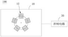
请参阅图1及图2,本发明实施方式的相机模组200包括两个镜头模组110。每个镜头模组110包括影像传感器100,每个影像传感器100包括像素阵列10和控制电路20。像素阵列10包括多个行像素和多个列像素。控制电路20用于控制影像传感器100工作于成像模式或光感模式。Please refer to FIG. 1 and FIG. 2 , the
控制电路20还用于:The
在影像传感器100工作于光感模式时,接收光感指令以控制像素阵列10的部分行像素及部分列像素的交叉区域12检测光照强度;和When the
在影像传感器100工作于成像模式时,接收成像指令以控制像素阵列10获取影像。When the
本发明实施方式的影像传感器100中,由于同一个影像传感器100具有成像模式和光感模式,避免手机等电子装置中同时设置一个摄像元件及一个光感元件,使得手机等电子装置中用于布置显示屏的空间较大,扩大手机屏占比。In the
可以理解,在每个影像传感器100中,每个行像素和每个列像素均包括多个像素。每个像素均可以获取光照强度信号和影像信号。因此,在影像传感器100工作于成像模式时,像素阵列10可以获取形成在像素阵列10表面上的外界影像。在影像传感器100工作于光感模式时,像素阵列10可以获取照射在像素上的光线的光照强度。It can be understood that in each
具体地,控制电路20根据光感指令控制交叉区域12进行感光。当前场景的光线到达交叉区域12的每个像素上,交叉区域12中每个像素对应的感光器件会产生电压变化从而获得与每个像素对应的像素值。根据上述的一系列像素值进行计算后得到光照强度。Specifically, the
控制电路20根据成像指令控制像素阵列10获取影像。当前场景的光线到达像素阵列10的每个像素上,像素阵列10中的每个像素对应的感光器件会产生电压变化从而获得与每个像素对应的像素值。根据上述的一系列像素值进行插值去马赛克等处理后可以获取最终的影像。The
需要说明的是,在影像传感器100工作于成像模式时,可以控制像素阵列10中的全部像素获取影像,当然,也可以控制像素阵列10中部分的像素获取影像。也即是说,像素阵列10的成像区域可以为像素阵列10的整个区域,也可以为像素阵列10的部分区域。It should be noted that when the
交叉区域12作为像素阵列10的光感区域,可包括多个像素,形成交叉区域12的每个像素均对应于相应的行像素和相应的列像素。例如,形成交叉区域12的其中一个像素对应于第4行像素和第4列像素。控制电路20可以控制像素阵列10中的每个像素单独工作,从而控制交叉区域12处于工作状态,而其他区域处于待工作状态。The
在一个例子中,其中一个行像素与一个开关连接,其中一个列像素与另一个开关连接,当以上两个开关同时关闭时,则行像素与列像素交叉对应的像素工作。如图3中的示例,第3行像素与第16列像素交叉对应的像素为P1,第3行像素与第一开关S1连接,第16列像素与第二开关S2连接,当第一开关S1和第二开关S2同时关闭时,则像素P1工作。当然,在其他实施方式中,还可以通过其他方式控制单个像素工作,例如,每个像素连接单个开关,单个开关闭合时,相应的像素开始工作。In an example, one row pixel is connected to one switch, and one column pixel is connected to another switch, and when the above two switches are closed at the same time, the pixel corresponding to the intersection of the row pixel and the column pixel works. 3, the pixel corresponding to the intersection of the pixel in the 3rd row and the pixel in the 16th column is P1, the pixel in the 3rd row is connected with the first switch S1, and the pixel in the 16th column is connected with the second switch S2, when the first switch S1 When the second switch S2 is turned off at the same time, the pixel P1 works. Of course, in other embodiments, a single pixel can also be controlled to work in other ways, for example, each pixel is connected to a single switch, and when the single switch is closed, the corresponding pixel starts to work.
需要指出的是,在影像传感器100工作于成像模式时,交叉区域12也可以获取外界影像。另外,本实施方式中,像素阵列10呈方形。在其他实施方式中,像素阵列10可呈多边形或圆形等其他形状,在此不作限定。It should be pointed out that, when the
可以理解,由于相机模组200包括两个镜头模组110,每个镜头模组110包括影像传感器100,因此,相机模组200包括两个影像传感器100。两个影像传感器100分别可以工作于成像模式或光感模式或待工作模式。It can be understood that since the
如图1的方位所示,左边的影像传感器100和右边的影像传感器100可以分别处于成像模式或光感模式或待工作模式。本实施方式的相机模组200可应用于电子装置300。因此,电子装置300的工作状态包括以下表1中的9种情况:As shown in the orientation of FIG. 1 , the
表1Table 1

需要说明的是,影像传感器100的待工作模式指的是,影像传感器100既不处于成像模式,也不处于光感模式,影像传感器100无法检测光照强度及获取影像。It should be noted that the standby mode of the
在一个例子中,左边的影像传感器100处于成像模式及右边的影像传感器100也处于成像模式时,左边的镜头模组110和右边的镜头模组110均可以获取影像。In one example, when the
例如,左边的镜头模组110可以为广角镜头模组,右边的镜头模组110可以为长焦镜头模组,左边的镜头模组110可以获取广角影像,右边的镜头模组110可以获取长焦影像,将广角影像和长焦影像融合后可以得到品质较佳的影像。For example, the
在另一个例子中,两个镜头模组110均获取影像时,两个镜头模组110同时成像得到多帧第一影像和多帧第二影像。处理器310可以对多帧第一影像和多帧第二影像进行分析筛选出成像质量最优的一帧影像作为最终的影像。或者,处理器310将第一影像和第二影像进行融合或拼接处理,实现最终的影像的颜色或清晰度的增强。In another example, when both
在另一个例子中,其中一个镜头模组110可以用于辅助另一个镜头模组110成像,从而优化成像质量。例如,其中一个镜头模组110首先检测当前场景的亮度,处理器310分析检测得的亮度值以控制另一个镜头模组110中各个像素对应的感光元件的曝光时间从而获取合适亮度的影像。如此,相机模组200成像时首先利用其中一个镜头模组110检测环境亮度以辅助另一个镜头模组110成像,保证最终获得的影像不会出现过曝或亮度偏低的问题,提升影像获取的质量。In another example, one of the
以下将对每个影像传感器100进行具体描述:Each
在一些实施方式中,交叉区域12位于像素阵列10的中心位置,如图2所示。In some embodiments, the
如此,光线容易到达位于像素阵列10的中心位置的交叉区域12,使得影像传感器100容易检测光线的强度,影像传感器100检测光线强度的敏感度较佳。In this way, the light can easily reach the
当然,在一些实施方式中,交叉区域12为环形交叉区域12,环形交叉区域12环绕像素阵列10的中心设置,如图4及图5所示。Of course, in some embodiments, the
具体地,在一些实施方式中,环形交叉区域12呈圆环形,如图4所示。需要说明的是,由于环形交叉区域12包括多个像素,而每个像素可为圆形或多边形等形状,因此,环形交叉区域12的内外边界线可为由多个线段连接而形成,并且大致呈圆形。Specifically, in some embodiments, the
在一些实施方式中,环形交叉区域12也可以呈方环形,如图5所示。当然,在其他实施方式中,环形交叉区域12也可以呈除圆环形和方环形外的其他形状,例如呈不规则形状的环形。In some embodiments, the
较佳地,交叉区域12以像素阵列10的中心呈中心对称设置。如此,像素阵列10的中心周围的区域均能检测光照强度,从而可以提高影像传感器100检测光照强度的灵敏度。Preferably, the
在一些实施方式中,交叉区域12的数量为至少两个,至少两个交叉区域12绕像素阵列10的中心均匀间隔分布。例如,交叉区域12的数量为两个、三个、四个或五个等数量。In some embodiments, the number of the
交叉区域12的具体数量可以根据实际情况具体设定,在此不作限定。另外,每个交叉区域12的形状可为圆形、扇形、多边形等形状,在此不作限定。The specific number of the
在一个例子中,交叉区域12的数量为两个时,两个交叉区域12分别对称地设置于像素阵列10的中心的左右两侧,如图6所示。In an example, when the number of the
具体地,当影像传感器100应用于手机等电子装置300中时,如图11所示,像素阵列10的左右方向对应于电子装置300的横向,也就是说,两个交叉区域12沿电子装置300的横向并列设置,使得电子装置300在横向上倾斜时,交叉区域12均能检测到光照强度,有利于提高影像传感器100检测光照强度的敏感度。Specifically, when the
在另一个例子中,交叉区域12的数量为两个时,两个交叉区域12分别对称地设置于像素阵列10的中心的上下两侧,如图7所示。In another example, when the number of the
具体地,当影像传感器100应用于手机等电子装置300中时,像素阵列10的上下方向对应于电子装置300的纵向,也就是说,两个交叉区域12沿电子装置300的纵向并列设置,使得电子装置300在纵向上倾斜时,交叉区域12均能检测到光照强度,有利于提高影像传感器100检测光照强度的敏感度。Specifically, when the
在又一个例子中,交叉区域12的数量为四个时,其中两个交叉区域12分别对称地设置于像素阵列10的中心的左右两侧,另外两个交叉区域12分别对称地设置于像素阵列10的中心的上下两侧,如图8所示。In yet another example, when the number of the
需要指出的是,以上的电子装置300的横向例如为图11中所示的左右方向,电子装置300的纵向例如为图11中所示的上下方向。It should be noted that, the horizontal direction of the above
在再一个例子中,交叉区域12的数量为五个时,交叉区域12绕像素阵列10的中心均匀间隔分布。也就是说,相邻的两个交叉区域12与像素阵列10的中心之间形成的夹角为72°,如图9所示。In yet another example, when the number of the
在一些实施方式中,在交叉区域12的数量为多个时,全部的交叉区域12的面积均相等。In some embodiments, when the number of the
需要说明的是,在像素阵列10呈规则图形时,像素阵列10的中心为规则图形的几何中心。例如,在像素阵列10呈圆形时,像素阵列10的中心为圆心。又如,在像素阵列10呈方形时,像素阵列10的中心为方形对角线的交叉点。It should be noted that, when the
在像素阵列10呈不规则图形时,像素阵列10的中心为像素阵列10的重心。When the
在一些实施方式中,交叉区域12的面积A1与像素阵列10的面积A2的比值A1/A2范围为[0.1,0.4]。,即0.1≤A1/A2≤0.4。例如,A1/A2为0.15、0.2、0.25、0.3、0.35等数值。In some embodiments, the ratio A1/A2 of the area A1 of the
A1/A2在以上数值范围时,像素阵列10在保证检测光照强度的同时,可以减少需要工作的像素的数量,以降低影像传感器100的功耗。When A1/A2 is in the above numerical range, the
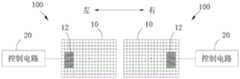
请参阅图10,在一些实施方式中,两个影像传感器100中的交叉区域12彼此远离地设置在对应的影像传感器100的一侧。Referring to FIG. 10 , in some embodiments, the
在图10的示例中,左边的交叉区域12设置在左边的影像传感器100的左侧,右边的交叉区域12设置在右边的影像传感器100的右侧。这样使得相机模组200检测光照强度的范围更广,检测的准确度更高。In the example of FIG. 10 , the
请再次参阅图1,在一些实施方式中,每个镜头模组110包括滤光片210。滤光片210设置于影像传感器100上方。Referring again to FIG. 1 , in some embodiments, each
较佳地,滤光片210为RGB滤光片210,以使影像传感器100获取较佳的图像。RGB滤光片210可以是以拜耳阵列排列,以使光线穿过滤光片210后通过像素阵列10以获取彩色的影像。Preferably, the
当然,在一些实施方式中,滤光片210可以是可见光滤光片210。如此,光线经过可见光滤光片210后,光线中仅可见光部分到达像素阵列10,而其他波段的光线被阻止,交叉区域12可用于检测可见光的光照强度,像素阵列10还可用于获取影像,避免了光线中不可见光的干扰,提升了光感检测的准确性及影响获取的品质。Of course, in some embodiments, the
在一些实施方式中,每个镜头模组110还包括镜头220,镜头220设置于滤光片210的上方。镜头220的光轴222与影像传感器100的中心对齐。In some embodiments, each
如此,从镜头220穿过的光线可以较均匀地到达影像传感器100的各个区域,以使影像传感器100的成像效果较佳,并且可以较好地检测光照强度。In this way, the light passing through the
具体地,在一些实施方式中,相机模组200还包括电路板230和外壳240。两个影像传感器100均设置于电路板230上。两个镜头220设置于外壳240内,并且与外壳240固定连接。Specifically, in some embodiments, the
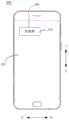
请参阅图11,本发明实施方式的电子装置300包括以上任一实施方式的相机模组200和处理器310,处理器310用于生成光感指令和成像指令。电子装置300例如为手机、平板电脑或智能穿戴设备等具有显示屏的设备。Referring to FIG. 11 , an
本发明实施方式的电子装置300中,由于同一个影像传感器100具有成像模式和光感模式,避免手机等电子装置300同时设置一个摄像元件及一个光感元件,使得手机中用于布置显示屏的空间较大,手机屏占比较高。In the
具体地,处理器310将光感指令或成像指令发送给控制电路20。处理器310可以单独生成并发送光感指令,或者单独生成并发送成像指令。Specifically, the
光感指令和成像指令可以是处理器310在接收到输入操作时生成,输入操作可以是用户输入的操作或者是应用环境的输入。The light sensing instruction and the imaging instruction may be generated by the
例如,在本发明实施例的手机中,光感指令和成像指令可以是处理器310接收到用户在手机上触摸或按压指定功能键的操作后生成。For example, in the mobile phone of the embodiment of the present invention, the light sensing instruction and the imaging instruction may be generated after the
又如,光感指令和成像指令也可以是处理器310依据手机的系统时间到达预定的时间点后生成。控制电路20可用于单独接收光感指令以控制交叉区域12检测光照强度,或者单独接收成像指令以控制像素阵列10获取影像。For another example, the light sensing instruction and the imaging instruction may also be generated after the
需要说明的是,处理器310可以将光感指令或成像指令发送给其中一个控制电路20,以控制对应的像素阵列10工作;处理器310也可以将光感指令或成像指令同时发送给两个控制电路20,以同时控制两个像素阵列10工作。两个影像传感器100的工作模式如以上的表1所示。It should be noted that the
请参图11,在一些实施方式中,电子装置300包括单个相机模组200,单个相机模组200为前置相机模组201。如此,单个相机模组200可以获取电子装置300的显示屏320前方的光照强度或物体的影像。可以理解,处理器310可以根据前置相机模组201中的两个影像传感器100获取的光照强度控制电子装置300的显示屏320亮度。Referring to FIG. 11 , in some embodiments, the
具体地,在一个例子中,在两个像素阵列10中的交叉区域12分别检测光照强度以得到第一光照强度L1和第二光照强度L2时,处理器310用于从第一光照强度L1和第二光照强度L2中选取较大者以作为最终光照强度Lf,即Lf=Max{L1,L2}。Specifically, in one example, when the
在另一个例子中,在两个像素阵列10中的交叉区域12分别检测光照强度以得到第一光照强度L1和第二光照强度L2时,处理器310用于计算第一光照强度L1和第二光照强度L2的平均值以得到最终光照强度Lf,即Lf=(L1+L2)/2。In another example, the
因此,处理器310可以根据最终强度Lf控制显示屏320的亮度,例如,处理器310根据最终光照强度Lf将显示屏320的亮度调高或调低。Therefore, the
需说明的是,用于控制显示屏320的亮度的最终强度Lf可以根据实际情况具体设定,处理器310可以在任何情况下切换以上任一个例子中的最终强度Lf以控制显示屏320的亮度。另外,第一光照强度L1由其中一个影像传感器100获得,第二光照强度L2由另一个影像传感器100获得。It should be noted that the final intensity Lf used to control the brightness of the
可以理解,电子装置300的壳体302开设有通光孔,以供光线进入相机模组200后到达影像传感器100,从而使电子装置300实现检测光线强度和获取影像的功能。It can be understood that the
当然,在一些实施方式中,电子装置300包括两个相机模组200,其中一个相机模组200为前置相机模组201,另一个相机模组200为后置相机模组202,如图12所示。Of course, in some embodiments, the
可以理解,前置相机模组201包括两个影像传感器100,后置相机模组202也包括两个影像传感器100,在四个影像传感器100中,每个影像传感器100可处于成像模式或光感模式或待工作模式。为了方便描述,以下可称前置相机模组201中的两个影像传感器100分别为第一影像传感器和第二影像传感器,可称后置相机模组202中的两个影像传感器100分别为第三影像传感器和第四影像传感器。因此,当电子装置300中设置前置相机模组201和后置相机模组202时,电子装置300的工作状态包括以下表2中的情况。It can be understood that the
表2Table 2

需要说明的是,在表2中,电子装置300的工作状态可以根据四个影像传感器100中的每个影像传感器的工作模式进行组合。It should be noted that, in Table 2, the working states of the
在某些实施方式中,在前置相机模组201的两个所述影像传感器100均工作于成像模式时,后置相机模组202的两个影像传感器100中的至少一个影像传感器100工作于光感模式。In some embodiments, when both of the
如此,处理器310可以根据后置相机模组202的影像传感器100检测到的光照强度控制前置相机模组201拍摄,以得到品质较佳的图像。例如,当后置相机模组202的影像传感器100检测到的光照强度较弱时,处理器310可以控制前置相机模组201增大曝光时间已获得亮度较佳的图像。In this way, the
同理,在某些实施方式中,在后置相机模组202的两个所述影像传感器100均工作于成像模式时,前置相机模组201的两个影像传感器100中的至少一个影像传感器100工作于光感模式。Similarly, in some embodiments, when the two
在电子装置300的使用过程中,前置相机模组201中的影像传感器100和后置相机模组202中的影像传感器100均获取光照强度时。电子装置300可以同时获取前置相机模组201周围的光线强度和后置相机模组202周围的光线强度。例如,在处理器310未生成所述成像指令时,前置相机模组201中的至少一个影像传感器100和后置相机模组202中的至少一个影像传感器100均工作于光感模式。During the use of the
以电子装置300为手机为例,用户在使用中可能存在电子装置300的正面与背面的光照强度相差较大的情况。例如,用户可能将手机正面朝下放在桌面上,如果仅仅依据前置相机模组201检测得到的正面光照强度控制显示屏320的显示亮度,此时显示屏320可能处于不显示或显示亮度极低的状态。当用户突然重新拿起电子装置300并使用时,电子装置300需要重新唤醒显示屏320或者将显示屏320的亮度在短时间内调高。当用户频繁拿起和放下时,电子装置300为了控制显示显示屏320的亮度的切换的操作需要耗费的电能较多。Taking the
本发明实施方式的电子装置300可同时检测电子装置300的正面和背面光照强度,当用户将手机正面朝下防止在桌面上时,显示屏320的亮度在一定时间范围内可根据背面光照强度的亮度显示,当用户重新拿起电子装置300使用时,显示屏320无需要切换显示亮度,使用方便且节约电能。The
在一些实施方式中,四个影像传感器100均用于检测光照强度时,处理器310可以根据四个影像传感器100检测到的光照强度控制显示屏320的亮度。In some embodiments, when the four
在一个例子中,在前置相机模组201的两个像素阵列10中的交叉区域12分别检测光照强度以得到第一光照强度L1和第二光照强度L2,且在后置相机模组202的两个像素阵列10中的交叉区域12分别检测光照强度以得到第三光照强度L3和第四光照强度L4时,处理器310用于从第一光照强度L1、第二光照强度L2、第三光照强度L3及第四光照强度L4中选取较大者以作为最终光照强度Lf,即Lf=Max{L1,L2,L3,L4}。In one example, the light intensity is detected in the
在另一个例子中,在前置相机模组201的两个像素阵列10中的交叉区域12分别检测光照强度以得到第一光照强度L1和第二光照强度L2,且在后置相机模组202的两个像素阵列10中的交叉区域12分别检测光照强度以得到第三光照强度L3和第四光照强度L4时,处理器310用于计算第一光照强度L1和第二光照强度L2的平均值以得到前置光照强度Lq,及计算第三光照强度L3和第四光照强度L4的平均值以得到后置光照强度Lh,及从前置光照强度及后置光照强度中选取较大者以作为最终光照强度Lf,即Lq=(L1+L2)/2,Lh=(L3+L4)/2,Lf=Max{Lq,Lh}。In another example, the light intensity is respectively detected in the
在又一个例子中,在前置相机模组201的两个像素阵列10中的交叉区域12分别检测光照强度以得到第一光照强度L1和第二光照强度L2,且在后置相机模组202的两个像素阵列10中的交叉区域12分别检测光照强度以得到第三光照强度L3和第四光照强度L4时,处理器310用于从第一光照强度L1和第二光照强度L2中选取较大者以作为前置光照强度Lq,及计算第三光照强度L3和第四光照强度L4的平均值以得到后置光照强度Lh,及从前置光照强度Lq及后置光照强度Lh中选取较大者以作为最终光照强度Lf,即Lq=Max{L1,L2},Lh=(L3+L4)/2,Lf=Max{Lq,Lh}。In yet another example, the light intensity is respectively detected in the
在再一个例子中,在前置相机模组201的两个像素阵列10中的交叉区域12分别检测光照强度以得到第一光照强度L1和第二光照强度L2,且在后置相机模组202的两个像素阵列10中的交叉区域12分别检测光照强度以得到第三光照强度L3和第四光照强度L4时,处理器310用于计算第一光照强度L1和第二光照强度L2的平均值以得到前置光照强度Lq,及从第三光照强度L3和第四光照强度L4选取较大者以作为后置光照强度Lh,及从前置光照强度Lq及后置光照强度Lh中选取较大者以作为最终光照强度Lf,即Lq=(L1+L2)/2,Lh=Max{L3,L4},Lf=Max{Lq,Lh}。In yet another example, the light intensity is detected in the
因此,处理器310可以根据最终强度Lf控制显示屏320的亮度,需说明的是,用于控制显示屏320的亮度的最终强度Lf可以根据实际情况具体设定,处理器310可以在任何情况下切换以上任一例子中的最终强度Lf以控制显示屏320的亮度。Therefore, the
在一些实施方式中,在前置相机模组201的两个像素阵列10中的交叉区域12分别检测光照强度以得到第一光照强度L1和第二光照强度L2,且在后置相机模组202的其中一个像素阵列10中的交叉区域12检测光照强度以得到第三光照强度L3时,处理器310可以根据第一光照强度L1、第二光照强度L2和第三光照强度L3控制显示屏320的亮度。In some embodiments, the light intensity is respectively detected in the
在一个例子中,处理器310用于从第一光照强度L1和第二光照强度L2中选取较大者以作为前置光照强度Lq,及从前置光照强度Lq及第三光照强度L3中选取较大者以作为最终光照强度Lf,即Lq=Max{L1,L2},Lf=Max{Lq,L3}。In one example, the
在另一个例子中,处理器310用于计算第一光照强度L1和第二光照强度L2的平均值以得到前置光照强度Lq,及从前置光照强度Lq及第三光照强度L3中选取较大者以作为最终光照强度Lf,即Lq=(L1+L2)/2,Lf=Max{Lq,L3}。In another example, the
因此,处理器310可以根据最终光照强度Lf控制显示屏320的亮度。因此,处理器310可以根据最终强度Lf控制显示屏320的亮度,需说明的是,用于控制显示屏320的亮度的最终强度Lf可以根据实际情况具体设定,处理器310可以在任何情况下切换以上任一例子中的最终强度Lf以控制显示屏320的亮度。Therefore, the
在一些实施方式中,在前置相机模组201的其中一个像素阵列10中的交叉区域12检测光照强度以得到第一光照强度L1时,在后置相机模组202的两个像素阵列10中的交叉区域12分别检测光照强度以得到第二光照强度L2和第三光照强度L3,处理器310可以根据第一光照强度L1、第二光照强度L2和第三光照强度L3控制显示屏320的亮度。In some embodiments, when the light intensity is detected in the
在一个例子中,处理器310用于从第二光照强度L2和第三光照强度L3中选取较大者以作为后置光照强度Lh,及从后置光照强度Lh及第一光照强度L1中选取较大者以作为最终光照强度Lf,即Lh=Max{L2,L3},Lf=Max{Lh,L1}。In one example, the
在另一个例子中,处理器310用于计算第二光照强度L2和第三光照强度L3的平均值以得到后置光照强度Lh,及从后置光照强度Lh及第一光照强度L1中选取较大者以作为最终光照强度Lf,即Lh=(L2+L3)/2,Lf=Max{Lh,L1}。In another example, the
因此,处理器310可以根据最终强度Lf控制显示屏320的亮度,需说明的是,用于控制显示屏320的亮度的最终强度Lf可以根据实际情况具体设定,处理器310可以在任何情况下切换以上任一例子中的最终强度Lf以控制显示屏320的亮度。Therefore, the
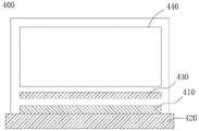
请参图11-图15,在某些实施方式中,电子装置300还包括单个摄像模组400,摄像模组400包括图像传感器410,图像传感器410包括像素阵列412和控制电路414。图像传感器410的像素阵列412包括多个行像素和多个列像素。图像传感器410的控制电路414用于控制图像传感器410工作于成像模式或光感模式,图像传感器410的控制电路414还用于:Referring to FIGS. 11-15 , in some embodiments, the
接收图像传感器410的光感指令以控制图像传感器410的像素阵列412的部分行像素及图像传感器410的像素阵列412的部分列像素的交叉区域416检测光照强度,以使图像传感器410工作于光感模式;和Receive a light-sensing command from the
接收图像传感器410的影像指令以控制图像传感器410的像素阵列412获取影像,以使图像传感器410工作于成像模式。Receive an image command from the
需要说明的是,图像传感器410与影像传感器100基本相同,以上影像传感器100的解释说明适用于本实施方式的图像传感器410。例如,图像传感器410的交叉区域416可位于图像传感器410的像素阵列412的中心位置。因此,本实施方式的图像传感器410其他未展开的部分可参考以上的影像传感器100相同或类似的部分,在此不再赘述。It should be noted that the
另外,在一些实施方式中,摄像模组400还包括电路板420、滤光片430和镜头440。图像传感器410设置在摄像模组400的电路板420上。摄像模组400的滤光片430设置于图像传感器410的上方,摄像模组400的镜头440设置于摄像模组400的滤光片430的上方。In addition, in some embodiments, the
在一些实施方式中,相机模组200的数量为单个,单个相机模组200为前置相机模组,摄像模组400为后置摄像模组400。或者,相机模组200的数量为单个,单个相机模组200为后置相机模组,摄像模组400为前置摄像模组,如图13所示。In some embodiments, the number of
可以理解,电子装置300还包括电池、供电电路和存储器等元件。电池用于为电子装置300提供电能。供电电路与电池连接,并用于为电子装置300供电。存储器用于存储数据信息,例如程序代码段。It can be understood that the
此外,术语“第一”、“第二”仅用于描述目的,而不能理解为指示或暗示相对重要性或者隐含指明所指示的技术特征的数量。由此,限定有“第一”、“第二”的特征可以明示或者隐含地包括一个或者更多个所述特征。在本发明的实施方式的描述中,“多个”的含义是两个或两个以上,除非另有明确具体的限定。In addition, the terms "first" and "second" are only used for descriptive purposes, and should not be construed as indicating or implying relative importance or implying the number of indicated technical features. Thus, features defined as "first", "second" may expressly or implicitly include one or more of said features. In the description of the embodiments of the present invention, "plurality" means two or more, unless otherwise expressly and specifically defined.
在本发明的实施方式的描述中,需要说明的是,除非另有明确的规定和限定,术语“安装”、“相连”、“连接”应做广义理解,例如,可以是固定连接,也可以是可拆卸连接,或一体地连接;可以是机械连接,也可以是电连接或可以相互通讯;可以是直接相连,也可以通过中间媒介间接相连,可以是两个元件内部的连通或两个元件的相互作用关系。对于本领域的普通技术人员而言,可以根据具体情况理解上述术语在本发明的实施方式中的具体含义。In the description of the embodiments of the present invention, it should be noted that, unless otherwise expressly specified and limited, the terms "installed", "connected" and "connected" should be understood in a broad sense, for example, it may be a fixed connection or a It is a detachable connection, or an integral connection; it can be a mechanical connection, an electrical connection or can communicate with each other; it can be directly connected or indirectly connected through an intermediate medium, it can be the internal connection of two components or two components interaction relationship. For those of ordinary skill in the art, the specific meanings of the above terms in the embodiments of the present invention can be understood according to specific situations.
上文的公开提供了许多不同的实施方式或例子用来实现本发明的实施方式的不同结构。为了简化本发明的实施方式的公开,上文中对特定例子的部件和设置进行描述。当然,它们仅仅为示例,并且目的不在于限制本发明。此外,本发明的实施方式可以在不同例子中重复参考数字和/或参考字母,这种重复是为了简化和清楚的目的,其本身不指示所讨论各种实施方式和/或设置之间的关系。此外,本发明的实施方式提供了的各种特定的工艺和材料的例子,但是本领域普通技术人员可以意识到其他工艺的应用和/或其他材料的使用。The above disclosure provides many different embodiments or examples for implementing different structures of embodiments of the invention. In order to simplify the disclosure of the embodiments of the present invention, the components and arrangements of specific examples are described above. Of course, they are only examples and are not intended to limit the invention. Furthermore, embodiments of the present invention may repeat reference numerals and/or reference letters in different instances, such repetition is for the purpose of simplicity and clarity and does not in itself indicate the relationship between the various embodiments and/or arrangements discussed . In addition, the embodiments of the present invention provide examples of various specific processes and materials, but one of ordinary skill in the art will recognize the application of other processes and/or the use of other materials.
在本说明书的描述中,参考术语“一个实施方式”、“某些实施方式”、“示意性实施方式”、“示例”、“具体示例”或“一些示例”等的描述意指结合所述实施方式或示例描述的具体特征、结构、材料或者特点包含于本发明的至少一个实施方式或示例中。在本说明书中,对上述术语的示意性表述不一定指的是相同的实施方式或示例。而且,描述的具体特征、结构、材料或者特点可以在任何的一个或多个实施方式或示例中以合适的方式结合。In the description of this specification, reference to description of the terms "one embodiment," "some embodiments," "exemplary embodiment," "example," "specific example," or "some examples", etc., is intended to incorporate the A particular feature, structure, material, or characteristic described by an embodiment or example is included in at least one embodiment or example of the present invention. In this specification, schematic representations of the above terms do not necessarily refer to the same embodiment or example. Furthermore, the particular features, structures, materials or characteristics described may be combined in any suitable manner in any one or more embodiments or examples.
流程图中或在此以其他方式描述的任何过程或方法描述可以被理解为,表示包括一个或更多个用于实现特定逻辑功能或过程的步骤的可执行指令的代码的模块、片段或部分,并且本发明的优选实施方式的范围包括另外的实现,其中可以不按所示出或讨论的顺序,包括根据所涉及的功能按基本同时的方式或按相反的顺序,来执行功能,这应被本发明的实施例所属技术领域的技术人员所理解。Any description of a process or method in the flowcharts or otherwise described herein may be understood to represent a module, segment or portion of code comprising one or more executable instructions for implementing a specified logical function or step of the process , and the scope of the preferred embodiments of the invention includes alternative implementations in which the functions may be performed out of the order shown or discussed, including performing the functions substantially concurrently or in the reverse order depending upon the functions involved, which should It is understood by those skilled in the art to which the embodiments of the present invention belong.
在流程图中表示或在此以其他方式描述的逻辑和/或步骤,例如,可以被认为是用于实现逻辑功能的可执行指令的定序列表,可以具体实现在任何计算机可读介质中,以供指令执行系统、装置或设备(如基于计算机的系统、包括处理模块的系统或其他可以从指令执行系统、装置或设备取指令并执行指令的系统)使用,或结合这些指令执行系统、装置或设备而使用。就本说明书而言,"计算机可读介质"可以是任何可以包含、存储、通信、传播或传输程序以供指令执行系统、装置或设备或结合这些指令执行系统、装置或设备而使用的装置。计算机可读介质的更具体的示例(非穷尽性列表)包括以下:具有一个或多个布线的电连接部(电子装置),便携式计算机盘盒(磁装置),随机存取存储器(RAM),只读存储器(ROM),可擦除可编辑只读存储器(EPROM或闪速存储器),光纤装置,以及便携式光盘只读存储器(CDROM)。另外,计算机可读介质甚至可以是可在其上打印所述程序的纸或其他合适的介质,因为可以例如通过对纸或其他介质进行光学扫描,接着进行编辑、解译或必要时以其他合适方式进行处理来以电子方式获得所述程序,然后将其存储在计算机存储器中。The logic and/or steps represented in flowcharts or otherwise described herein, for example, may be considered an ordered listing of executable instructions for implementing the logical functions, may be embodied in any computer-readable medium, For use by an instruction execution system, apparatus or apparatus (such as a computer-based system, a system including a processing module, or other system that can fetch instructions from and execute instructions from an instruction execution system, apparatus or apparatus), or in conjunction with such instruction execution system, apparatus or equipment. For the purposes of this specification, a "computer-readable medium" can be any device that can contain, store, communicate, propagate, or transport the program for use by or in conjunction with an instruction execution system, apparatus, or apparatus. More specific examples (non-exhaustive list) of computer readable media include the following: electrical connections with one or more wiring (electronic devices), portable computer disk cartridges (magnetic devices), random access memory (RAM), Read Only Memory (ROM), Erasable Editable Read Only Memory (EPROM or Flash Memory), Fiber Optic Devices, and Portable Compact Disc Read Only Memory (CDROM). In addition, the computer readable medium may even be paper or other suitable medium on which the program may be printed, as the paper or other medium may be optically scanned, for example, followed by editing, interpretation, or other suitable medium as necessary process to obtain the program electronically and then store it in computer memory.
应当理解,本发明的实施方式的各部分可以用硬件、软件、固件或它们的组合来实现。在上述实施方式中,多个步骤或方法可以用存储在存储器中且由合适的指令执行系统执行的软件或固件来实现。例如,如果用硬件来实现,和在另一实施方式中一样,可用本领域公知的下列技术中的任一项或他们的组合来实现:具有用于对数据信号实现逻辑功能的逻辑门电路的离散逻辑电路,具有合适的组合逻辑门电路的专用集成电路,可编程门阵列(PGA),现场可编程门阵列(FPGA)等。It should be understood that various parts of the embodiments of the present invention may be implemented in hardware, software, firmware, or a combination thereof. In the above-described embodiments, various steps or methods may be implemented in software or firmware stored in memory and executed by a suitable instruction execution system. For example, if implemented in hardware, as in another embodiment, it can be implemented by any one or a combination of the following techniques known in the art: Discrete logic circuits, application specific integrated circuits with suitable combinational logic gates, Programmable Gate Arrays (PGA), Field Programmable Gate Arrays (FPGA), etc.
本技术领域的普通技术人员可以理解实现上述实施例方法携带的全部或部分步骤是可以通过程序来指令相关的硬件完成,所述的程序可以存储于一种计算机可读存储介质中,该程序在执行时,包括方法实施例的步骤之一或其组合。Those skilled in the art can understand that all or part of the steps carried by the methods of the above embodiments can be completed by instructing the relevant hardware through a program, and the program can be stored in a computer-readable storage medium, and the program can be stored in a computer-readable storage medium. When executed, one or a combination of the steps of the method embodiment is included.
此外,在本发明的各个实施例中的各功能单元可以集成在一个处理模块中,也可以是各个单元单独物理存在,也可以两个或两个以上单元集成在一个模块中。上述集成的模块既可以采用硬件的形式实现,也可以采用软件功能模块的形式实现。所述集成的模块如果以软件功能模块的形式实现并作为独立的产品销售或使用时,也可以存储在一个计算机可读取存储介质中。In addition, each functional unit in each embodiment of the present invention may be integrated into one processing module, or each unit may exist physically alone, or two or more units may be integrated into one module. The above-mentioned integrated modules can be implemented in the form of hardware, and can also be implemented in the form of software function modules. If the integrated modules are implemented in the form of software functional modules and sold or used as independent products, they may also be stored in a computer-readable storage medium.
上述提到的存储介质可以是只读存储器,磁盘或光盘等。The above-mentioned storage medium may be a read-only memory, a magnetic disk or an optical disk, and the like.
尽管上面已经示出和描述了本发明的实施例,可以理解的是,上述实施例是示例性的,不能理解为对本发明的限制,本领域的普通技术人员在本发明的范围内可以对上述实施例进行变化、修改、替换和变型。Although the embodiments of the present invention have been shown and described above, it should be understood that the above-mentioned embodiments are exemplary and should not be construed as limiting the present invention. Embodiments are subject to variations, modifications, substitutions and variations.
Claims (21)
Priority Applications (11)
| Application Number | Priority Date | Filing Date | Title |
|---|---|---|---|
| CN201710305887.9ACN107222664B (en) | 2017-05-03 | 2017-05-03 | Camera Modules and Electronic Devices |
| EP18169883.8AEP3399287B8 (en) | 2017-05-03 | 2018-04-27 | Camera assembly and mobile electronic device |
| ES18169883TES2761935T3 (en) | 2017-05-03 | 2018-04-27 | Camera and mobile electronic device set |
| US15/968,718US10554869B2 (en) | 2017-05-03 | 2018-05-01 | Camera assembly and mobile electronic device |
| SG11201906432XASG11201906432XA (en) | 2017-05-03 | 2018-05-02 | Camera assembly and mobile electronic device |
| KR1020197017537AKR20190077576A (en) | 2017-05-03 | 2018-05-02 | CAMERA ASSEMBLY AND MOBILE ELECTRONIC DEVICE |
| AU2018263023AAU2018263023B2 (en) | 2017-05-03 | 2018-05-02 | Camera assembly and mobile electronic device |
| CA3050024ACA3050024C (en) | 2017-05-03 | 2018-05-02 | Camera assembly and mobile electronic device |
| JP2019537327AJP6801114B2 (en) | 2017-05-03 | 2018-05-02 | Camera assembly and portable electronics |
| PCT/CN2018/085361WO2018202051A1 (en) | 2017-05-03 | 2018-05-02 | Camera assembly and mobile electronic device |
| IL268142AIL268142B (en) | 2017-05-03 | 2019-07-18 | Camera assembly and mobile electronic device |
Applications Claiming Priority (1)
| Application Number | Priority Date | Filing Date | Title |
|---|---|---|---|
| CN201710305887.9ACN107222664B (en) | 2017-05-03 | 2017-05-03 | Camera Modules and Electronic Devices |
Publications (2)
| Publication Number | Publication Date |
|---|---|
| CN107222664A CN107222664A (en) | 2017-09-29 |
| CN107222664Btrue CN107222664B (en) | 2020-03-06 |
Family
ID=59943991
Family Applications (1)
| Application Number | Title | Priority Date | Filing Date |
|---|---|---|---|
| CN201710305887.9AExpired - Fee RelatedCN107222664B (en) | 2017-05-03 | 2017-05-03 | Camera Modules and Electronic Devices |
Country Status (11)
| Country | Link |
|---|---|
| US (1) | US10554869B2 (en) |
| EP (1) | EP3399287B8 (en) |
| JP (1) | JP6801114B2 (en) |
| KR (1) | KR20190077576A (en) |
| CN (1) | CN107222664B (en) |
| AU (1) | AU2018263023B2 (en) |
| CA (1) | CA3050024C (en) |
| ES (1) | ES2761935T3 (en) |
| IL (1) | IL268142B (en) |
| SG (1) | SG11201906432XA (en) |
| WO (1) | WO2018202051A1 (en) |
Families Citing this family (14)
| Publication number | Priority date | Publication date | Assignee | Title |
|---|---|---|---|---|
| CN107135341B (en)* | 2017-05-03 | 2019-12-27 | Oppo广东移动通信有限公司 | Image sensor, camera module and electronic device |
| CN107426471B (en)* | 2017-05-03 | 2021-02-05 | Oppo广东移动通信有限公司 | Camera module and electronic device |
| CN107222664B (en)* | 2017-05-03 | 2020-03-06 | Oppo广东移动通信有限公司 | Camera Modules and Electronic Devices |
| CN107979698B (en)* | 2017-11-22 | 2020-05-12 | Oppo广东移动通信有限公司 | Ambient light intensity detection method and device, storage medium and electronic equipment |
| KR102434930B1 (en)* | 2018-04-04 | 2022-08-19 | 후아웨이 테크놀러지 컴퍼니 리미티드 | Ambient light detection method and terminal |
| CN108391038B (en) | 2018-04-24 | 2019-06-04 | Oppo广东移动通信有限公司 | Electronic device and camera assembly thereof |
| CN111989906B (en)* | 2018-07-16 | 2022-06-17 | Oppo广东移动通信有限公司 | Electronic equipment |
| CN109067942B (en) | 2018-08-03 | 2021-03-16 | Oppo广东移动通信有限公司 | Display screen and electronic device with same |
| USD891387S1 (en)* | 2019-01-30 | 2020-07-28 | Lg Electronics Inc. | Cellular phone |
| CN110166593B (en)* | 2019-05-20 | 2020-12-22 | Oppo广东移动通信有限公司 | Camera module and electronic equipment |
| US10885514B1 (en)* | 2019-07-15 | 2021-01-05 | Capital One Services, Llc | System and method for using image data to trigger contactless card transactions |
| CN111090104B (en)* | 2019-12-26 | 2022-11-11 | 维沃移动通信有限公司 | Imaging processing method and electronic device |
| CN117120816A (en) | 2021-03-31 | 2023-11-24 | 三星电子株式会社 | Method of illumination measurement using a camera and electronic device supporting the method |
| KR20220135986A (en)* | 2021-03-31 | 2022-10-07 | 삼성전자주식회사 | Method for measuring illuminance using camera and electronic device supporting the same |
Citations (3)
| Publication number | Priority date | Publication date | Assignee | Title |
|---|---|---|---|---|
| CN1669313A (en)* | 2002-07-11 | 2005-09-14 | 精工爱普生株式会社 | Output image adjustment of image data |
| CN104517585A (en)* | 2013-09-29 | 2015-04-15 | 联想(北京)有限公司 | Method and device for adjusting display screen |
| CN106303273A (en)* | 2016-07-29 | 2017-01-04 | 努比亚技术有限公司 | A kind of mobile terminal and camera control method thereof |
Family Cites Families (21)
| Publication number | Priority date | Publication date | Assignee | Title |
|---|---|---|---|---|
| JP2004015597A (en)* | 2002-06-10 | 2004-01-15 | Minolta Co Ltd | Electronic camera |
| JP2004241822A (en)* | 2003-02-03 | 2004-08-26 | Konica Minolta Holdings Inc | Mobile terminal |
| JP4270001B2 (en)* | 2004-03-29 | 2009-05-27 | 日本電気株式会社 | Mobile terminal device |
| JP4943695B2 (en)* | 2005-11-21 | 2012-05-30 | 富士フイルム株式会社 | Multifocal camera optical system |
| US20080122821A1 (en)* | 2006-11-24 | 2008-05-29 | Sony Ericsson Mobile Communications Ab | Luminance control for a display |
| US7683305B2 (en)* | 2007-09-27 | 2010-03-23 | Aptina Imaging Corporation | Method and apparatus for ambient light detection |
| CN101582985B (en) | 2008-12-09 | 2011-07-27 | 王玉龙 | Digital scene-touching technique camera |
| US20120092541A1 (en)* | 2010-10-19 | 2012-04-19 | Nokia Corporation | Method and apparatus for ambient light measurement system |
| KR20120067050A (en) | 2010-12-15 | 2012-06-25 | 엘지이노텍 주식회사 | Camera module and method for calculating mount shift thereof |
| US20130076712A1 (en)* | 2011-09-22 | 2013-03-28 | Dong Zheng | Distributed Light Sensors for Ambient Light Detection |
| US20140063288A1 (en)* | 2012-08-30 | 2014-03-06 | Pantech Co., Ltd. | Imaging apparatus, electronic device and method providing exposure compensation |
| CN104410787B (en) | 2012-12-28 | 2018-12-04 | 努比亚技术有限公司 | A kind of photographic device and image capture method |
| US9607571B2 (en)* | 2013-08-07 | 2017-03-28 | Beijing Lenovo Software Ltd. | Information processing method and electronic device |
| CN105493494B (en)* | 2013-08-30 | 2019-08-06 | 麦克赛尔株式会社 | Information processing device, information processing method, and storage medium |
| US9232150B2 (en)* | 2014-03-12 | 2016-01-05 | Apple Inc. | System and method for estimating an ambient light condition using an image sensor |
| US9277144B2 (en)* | 2014-03-12 | 2016-03-01 | Apple Inc. | System and method for estimating an ambient light condition using an image sensor and field-of-view compensation |
| CN104780316B (en) | 2015-04-14 | 2017-09-29 | 广东欧珀移动通信有限公司 | A camera startup detection method and camera startup detection device |
| CN107222664B (en) | 2017-05-03 | 2020-03-06 | Oppo广东移动通信有限公司 | Camera Modules and Electronic Devices |
| CN107426470B (en)* | 2017-05-03 | 2021-02-05 | Oppo广东移动通信有限公司 | Camera module and electronic device |
| CN107426471B (en)* | 2017-05-03 | 2021-02-05 | Oppo广东移动通信有限公司 | Camera module and electronic device |
| KR20190008610A (en)* | 2017-07-17 | 2019-01-25 | 엘지전자 주식회사 | Mobile terminal and Control Method for the Same |
- 2017
- 2017-05-03CNCN201710305887.9Apatent/CN107222664B/ennot_activeExpired - Fee Related
- 2018
- 2018-04-27EPEP18169883.8Apatent/EP3399287B8/enactiveActive
- 2018-04-27ESES18169883Tpatent/ES2761935T3/enactiveActive
- 2018-05-01USUS15/968,718patent/US10554869B2/enactiveActive
- 2018-05-02CACA3050024Apatent/CA3050024C/enactiveActive
- 2018-05-02WOPCT/CN2018/085361patent/WO2018202051A1/ennot_activeCeased
- 2018-05-02AUAU2018263023Apatent/AU2018263023B2/ennot_activeCeased
- 2018-05-02JPJP2019537327Apatent/JP6801114B2/ennot_activeExpired - Fee Related
- 2018-05-02KRKR1020197017537Apatent/KR20190077576A/ennot_activeCeased
- 2018-05-02SGSG11201906432XApatent/SG11201906432XA/enunknown
- 2019
- 2019-07-18ILIL268142Apatent/IL268142B/enactiveIP Right Grant
Patent Citations (3)
| Publication number | Priority date | Publication date | Assignee | Title |
|---|---|---|---|---|
| CN1669313A (en)* | 2002-07-11 | 2005-09-14 | 精工爱普生株式会社 | Output image adjustment of image data |
| CN104517585A (en)* | 2013-09-29 | 2015-04-15 | 联想(北京)有限公司 | Method and device for adjusting display screen |
| CN106303273A (en)* | 2016-07-29 | 2017-01-04 | 努比亚技术有限公司 | A kind of mobile terminal and camera control method thereof |
Also Published As
| Publication number | Publication date |
|---|---|
| AU2018263023A1 (en) | 2019-07-25 |
| WO2018202051A1 (en) | 2018-11-08 |
| US20180324342A1 (en) | 2018-11-08 |
| JP2020506587A (en) | 2020-02-27 |
| IL268142A (en) | 2019-09-26 |
| CA3050024A1 (en) | 2018-11-08 |
| AU2018263023B2 (en) | 2020-08-06 |
| EP3399287B8 (en) | 2019-12-25 |
| ES2761935T3 (en) | 2020-05-21 |
| IL268142B (en) | 2021-03-25 |
| EP3399287A1 (en) | 2018-11-07 |
| US10554869B2 (en) | 2020-02-04 |
| SG11201906432XA (en) | 2019-08-27 |
| CN107222664A (en) | 2017-09-29 |
| CA3050024C (en) | 2021-07-27 |
| JP6801114B2 (en) | 2020-12-16 |
| KR20190077576A (en) | 2019-07-03 |
| EP3399287B1 (en) | 2019-11-20 |
Similar Documents
| Publication | Publication Date | Title |
|---|---|---|
| CN107222664B (en) | Camera Modules and Electronic Devices | |
| CN107135341B (en) | Image sensor, camera module and electronic device | |
| AU2018263021B2 (en) | Camera assembly and mobile electronic device | |
| CN107426471B (en) | Camera module and electronic device | |
| CN107249109A (en) | Image sensor, camera module and electronic installation | |
| CN107222591B (en) | Image sensor, camera module and electronic device | |
| HK1244138B (en) | Camera module and electronic device | |
| HK1244138A1 (en) | Camera module and electronic device | |
| HK1244139A1 (en) | Camera module and electronic device | |
| HK1244140A1 (en) | Camera module and electronic device | |
| HK1244139B (en) | Camera module and electronic device |
Legal Events
| Date | Code | Title | Description |
|---|---|---|---|
| PB01 | Publication | ||
| PB01 | Publication | ||
| SE01 | Entry into force of request for substantive examination | ||
| SE01 | Entry into force of request for substantive examination | ||
| REG | Reference to a national code | Ref country code:HK Ref legal event code:DE Ref document number:1244138 Country of ref document:HK | |
| CB02 | Change of applicant information | ||
| CB02 | Change of applicant information | Address after:Changan town in Guangdong province Dongguan 523860 usha Beach Road No. 18 Applicant after:GUANGDONG OPPO MOBILE TELECOMMUNICATIONS Corp.,Ltd. Address before:Changan town in Guangdong province Dongguan 523860 usha Beach Road No. 18 Applicant before:GUANGDONG OPPO MOBILE TELECOMMUNICATIONS Corp.,Ltd. | |
| GR01 | Patent grant | ||
| GR01 | Patent grant | ||
| CF01 | Termination of patent right due to non-payment of annual fee | ||
| CF01 | Termination of patent right due to non-payment of annual fee | Granted publication date:20200306 |