CN107219710B - Multi-lens system and portable electronic device having the same - Google Patents
Multi-lens system and portable electronic device having the sameDownload PDFInfo
- Publication number
- CN107219710B CN107219710BCN201610159721.6ACN201610159721ACN107219710BCN 107219710 BCN107219710 BCN 107219710BCN 201610159721 ACN201610159721 ACN 201610159721ACN 107219710 BCN107219710 BCN 107219710B
- Authority
- CN
- China
- Prior art keywords
- lens
- reflection
- image sensing
- lenses
- sensing element
- Prior art date
- Legal status (The legal status is an assumption and is not a legal conclusion. Google has not performed a legal analysis and makes no representation as to the accuracy of the status listed.)
- Active
Links
Images


Classifications
- G—PHYSICS
- G03—PHOTOGRAPHY; CINEMATOGRAPHY; ANALOGOUS TECHNIQUES USING WAVES OTHER THAN OPTICAL WAVES; ELECTROGRAPHY; HOLOGRAPHY
- G03B—APPARATUS OR ARRANGEMENTS FOR TAKING PHOTOGRAPHS OR FOR PROJECTING OR VIEWING THEM; APPARATUS OR ARRANGEMENTS EMPLOYING ANALOGOUS TECHNIQUES USING WAVES OTHER THAN OPTICAL WAVES; ACCESSORIES THEREFOR
- G03B17/00—Details of cameras or camera bodies; Accessories therefor
- G03B17/02—Bodies
- G03B17/12—Bodies with means for supporting objectives, supplementary lenses, filters, masks, or turrets
- G03B17/14—Bodies with means for supporting objectives, supplementary lenses, filters, masks, or turrets interchangeably
- H—ELECTRICITY
- H04—ELECTRIC COMMUNICATION TECHNIQUE
- H04N—PICTORIAL COMMUNICATION, e.g. TELEVISION
- H04N23/00—Cameras or camera modules comprising electronic image sensors; Control thereof
- H04N23/60—Control of cameras or camera modules
- H04N23/698—Control of cameras or camera modules for achieving an enlarged field of view, e.g. panoramic image capture
- H—ELECTRICITY
- H04—ELECTRIC COMMUNICATION TECHNIQUE
- H04N—PICTORIAL COMMUNICATION, e.g. TELEVISION
- H04N23/00—Cameras or camera modules comprising electronic image sensors; Control thereof
- H04N23/50—Constructional details
- H04N23/55—Optical parts specially adapted for electronic image sensors; Mounting thereof
- G—PHYSICS
- G02—OPTICS
- G02B—OPTICAL ELEMENTS, SYSTEMS OR APPARATUS
- G02B13/00—Optical objectives specially designed for the purposes specified below
- G02B13/06—Panoramic objectives; So-called "sky lenses" including panoramic objectives having reflecting surfaces
- H—ELECTRICITY
- H04—ELECTRIC COMMUNICATION TECHNIQUE
- H04M—TELEPHONIC COMMUNICATION
- H04M1/00—Substation equipment, e.g. for use by subscribers
- H04M1/02—Constructional features of telephone sets
- H04M1/0202—Portable telephone sets, e.g. cordless phones, mobile phones or bar type handsets
- H04M1/026—Details of the structure or mounting of specific components
- H04M1/0264—Details of the structure or mounting of specific components for a camera module assembly
- H—ELECTRICITY
- H04—ELECTRIC COMMUNICATION TECHNIQUE
- H04N—PICTORIAL COMMUNICATION, e.g. TELEVISION
- H04N23/00—Cameras or camera modules comprising electronic image sensors; Control thereof
- H04N23/45—Cameras or camera modules comprising electronic image sensors; Control thereof for generating image signals from two or more image sensors being of different type or operating in different modes, e.g. with a CMOS sensor for moving images in combination with a charge-coupled device [CCD] for still images
- H—ELECTRICITY
- H04—ELECTRIC COMMUNICATION TECHNIQUE
- H04N—PICTORIAL COMMUNICATION, e.g. TELEVISION
- H04N23/00—Cameras or camera modules comprising electronic image sensors; Control thereof
- H04N23/58—Means for changing the camera field of view without moving the camera body, e.g. nutating or panning of optics or image sensors
- H—ELECTRICITY
- H04—ELECTRIC COMMUNICATION TECHNIQUE
- H04N—PICTORIAL COMMUNICATION, e.g. TELEVISION
- H04N23/00—Cameras or camera modules comprising electronic image sensors; Control thereof
- H04N23/60—Control of cameras or camera modules
- H04N23/667—Camera operation mode switching, e.g. between still and video, sport and normal or high- and low-resolution modes
Landscapes
- Engineering & Computer Science (AREA)
- Signal Processing (AREA)
- Multimedia (AREA)
- Physics & Mathematics (AREA)
- General Physics & Mathematics (AREA)
- Optics & Photonics (AREA)
- Human Computer Interaction (AREA)
- Studio Devices (AREA)
- Cameras In General (AREA)
- Stereoscopic And Panoramic Photography (AREA)
Abstract
Translated fromChinese
Description
Translated fromChinese技术领域technical field
本发明涉及一种多镜头系统及具有该多镜头系统的便携式电子装置。The present invention relates to a multi-lens system and a portable electronic device having the same.
背景技术Background technique
目前,移动电话、平板电脑及个人数字助理等便携式电子装置为了拍摄超广角或接近鱼眼全景的影像,通常需要于前后摄像头上外挂特殊的光学镜头。另外,虽然利用额外的两组鱼眼镜头亦可实现超广角或360度的全景拍摄。然而,由于该两组鱼眼镜头的取像角度太广,容易导致在拍摄较小范围内的特定主题时影像细腻度较差。另外,鱼眼镜头的成像变形率相较标准镜头的成像变形率具有较差、较高的问题。Currently, portable electronic devices such as mobile phones, tablet computers, and personal digital assistants usually need to attach special optical lenses to the front and rear cameras in order to capture images with ultra-wide angle or close to fisheye panorama. In addition, ultra-wide-angle or 360-degree panoramic shooting can also be achieved with the use of an additional two sets of fisheye lenses. However, because the image capturing angles of the two groups of fisheye lenses are too wide, it is easy to cause poor image fineness when shooting a specific subject within a small range. In addition, the imaging deformation rate of the fisheye lens has the problem of poorer and higher imaging deformation rate than that of the standard lens.
发明内容SUMMARY OF THE INVENTION
有鉴于此,有必要提供一种多镜头系统及具有该多镜头系统的便携式电子装置。In view of this, it is necessary to provide a multi-lens system and a portable electronic device having the same.
一种多镜头系统,包括至少一组镜头、至少一组反射单元、第一影像感测元件、第二影像感测元件以及处理单元,所述第一影像感测元件及第二影像感测元件均电连接至所述处理单元,所述处理单元用于根据拍摄模式控制所述至少一组反射单元的角度方向,以改变每一组反射单元的光学路径,进而选择相应的镜头或镜头组合,所述选择的镜头或镜头组合获取的影像光束通过相应的光学路径反射或投射至所述第一影像感测元件及第二影像感测元件。A multi-lens system includes at least one set of lenses, at least one set of reflection units, a first image sensing element, a second image sensing element and a processing unit, the first image sensing element and the second image sensing element are electrically connected to the processing unit, and the processing unit is used to control the angular direction of the at least one group of reflection units according to the shooting mode, so as to change the optical path of each group of reflection units, and then select the corresponding lens or lens combination, The image beam obtained by the selected lens or lens combination is reflected or projected to the first image sensing element and the second image sensing element through corresponding optical paths.
一种便携式电子装置,包括上述多镜头系统及显示单元,所述显示单元用以供用户设定所述拍摄模式。A portable electronic device includes the above-mentioned multi-lens system and a display unit, wherein the display unit is used for a user to set the shooting mode.
上述多镜头系统通过在便携式电子装置上设置包括多组镜头的镜头模组,并设置相应的反射模组。如此,所述处理单元可根据不同的需求选择相应的拍摄模式,并根据选择的拍摄模式控制所述反射模组中反射单元的角度方向,进而调整所述反射单元的光学路径,以选择不同的镜头或镜头组合。上述多镜头系统的结构简单,且可适用多种不同的拍摄模式,例如全景拍摄模式、普通的双镜头拍摄模式等等,具有较强的实用性。In the above-mentioned multi-lens system, a lens module including multiple sets of lenses is arranged on the portable electronic device, and a corresponding reflection module is arranged. In this way, the processing unit can select a corresponding shooting mode according to different needs, and control the angular direction of the reflection unit in the reflection module according to the selected shooting mode, and then adjust the optical path of the reflection unit to select different A lens or a combination of lenses. The above-mentioned multi-lens system has a simple structure, and can be applied to a variety of different shooting modes, such as a panoramic shooting mode, an ordinary dual-lens shooting mode, etc., and has strong practicability.
附图说明Description of drawings
图1为本发明较佳实施方式中多镜头系统应用至便携式电子装置的示意图。FIG. 1 is a schematic diagram illustrating the application of a multi-lens system to a portable electronic device according to a preferred embodiment of the present invention.
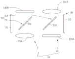
图2为图1所示多镜头系统的部分示意图。FIG. 2 is a partial schematic diagram of the multi-lens system shown in FIG. 1 .
图3为图1所示便携式电子装置的功能框图。FIG. 3 is a functional block diagram of the portable electronic device shown in FIG. 1 .
图4为图2所示多镜头系统处于第一拍摄模式时的光路图。FIG. 4 is an optical path diagram of the multi-lens system shown in FIG. 2 in a first shooting mode.
图5为图2所示多镜头系统处于第二拍摄模式时的光路图。FIG. 5 is an optical path diagram of the multi-lens system shown in FIG. 2 in a second shooting mode.
图6为图2所示多镜头系统处于第三拍摄模式时的光路图。FIG. 6 is an optical path diagram of the multi-lens system shown in FIG. 2 in a third shooting mode.
图7为图2所示多镜头系统处于第四拍摄模式时的光路图。FIG. 7 is an optical path diagram of the multi-lens system shown in FIG. 2 in a fourth shooting mode.
图8为图4所示多镜头系统中第一反射单元组及第二反射单元组均包括两个反射元件时的光路图。FIG. 8 is an optical path diagram when both the first reflection unit group and the second reflection unit group in the multi-lens system shown in FIG. 4 include two reflection elements.
图9为图5所示多镜头系统中第一反射单元组及第二反射单元组均包括两个反射元件时的光路图。FIG. 9 is an optical path diagram when both the first reflection unit group and the second reflection unit group in the multi-lens system shown in FIG. 5 include two reflection elements.
图10为图6所示多镜头系统中第一反射单元组及第二反射单元组均包括两个反射元件时的光路图。FIG. 10 is an optical path diagram when both the first reflection unit group and the second reflection unit group in the multi-lens system shown in FIG. 6 include two reflection elements.
图11为图7所示多镜头系统中第一反射单元组及第二反射单元组均包括两个反射元件时的光路图。FIG. 11 is an optical path diagram when both the first reflection unit group and the second reflection unit group in the multi-lens system shown in FIG. 7 include two reflection elements.
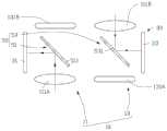
图12为图1所示多镜头系统于另一实施例下的部分示意图。FIG. 12 is a partial schematic diagram of the multi-lens system shown in FIG. 1 under another embodiment.
图13为图12所示多镜头系统处于第一拍摄模式时的光路图。FIG. 13 is an optical path diagram of the multi-lens system shown in FIG. 12 in the first shooting mode.
图14为图12所示多镜头系统处于第二拍摄模式时的光路图。FIG. 14 is an optical path diagram of the multi-lens system shown in FIG. 12 in the second shooting mode.
图15为图1所示多镜头系统的工作流程图。FIG. 15 is a flow chart of the operation of the multi-lens system shown in FIG. 1 .
主要元件符号说明Description of main component symbols
如下具体实施方式将结合上述附图进一步说明本发明。The following specific embodiments will further illustrate the present invention in conjunction with the above drawings.
具体实施方式Detailed ways
请参阅图1,本发明较佳实施例提供一种多镜头系统100,其可应用于移动电话、平板电脑及个人数字助理等便携式电子装置200。所述便携式电子装置200包括本体21。所述本体21包括第一表面211及与所述第一表面211相对设置的第二表面213。所述第一表面211上设置有显示单元23。所述显示单元23可以为触控显示屏,其用于显示用户界面,进而供用户操作及显示画面。Referring to FIG. 1, a preferred embodiment of the present invention provides a
请一并参阅图2及图3,所述多镜头系统100可以是便携式电子装置200的一部分,其装设于所述便携式电子装置200的一端。该多镜头系统100包括镜头模组10、影像感测模组30、反射模组50以及处理单元70。Please refer to FIG. 2 and FIG. 3 together, the
在本实施例中,该镜头模组10包括二组镜头,即第一镜头组11及第二镜头组13。其中第一镜头组11包括第一镜头111A及第一镜头111B。该第一镜头111A及第一镜头111B为同样的镜头,该第一镜头111A及该第一镜头111B可以为鱼眼镜头或其他类型的广角镜头等。该第一镜头111A及第一镜头111B分别设置于所述便携式电子装置200的第一表面211及第二表面213,且两者的光轴相互重叠,即两者对称地布置于同一光轴两端。所述第二镜头组13包括第二镜头131A及第二镜头131B。该第二镜头131A及第二镜头131B为同样的镜头。该第二镜头131A及该第二镜头131B可以为普通的摄像镜头或功能镜头等。该第二镜头131A及第二镜头131B分别设置于所述便携式电子装置200的第一表面211及第二表面213,且两者的光轴相互重叠,即两者对称地布置于同一光轴两端。In this embodiment, the
当然,可以理解的是,在其他实施例中,所述第一镜头组11的第一镜头111A、第一镜头111B与第二镜头组13的第二镜头131A、第二镜头131B为具有不同视野范围FOV (Fieldof View)的镜头,并不限定于鱼眼镜头或其他类型的广角镜头。Of course, it can be understood that in other embodiments, the
可以理解,不同类型的镜头或镜头组合可用于实现不同的拍摄功能。例如当同时选择第一镜头组11的第一镜头111A及第一镜头111B时,可实现第一拍摄模式,如此可拍摄超广度或者接近鱼眼全景的影像,即实现全景拍摄模式。当同时选择第二镜头组13的第二镜头131A及第二镜头131B时,可实现第二拍摄模式,即实现一般主题的拍摄模式。当选择位于本体21的第一表面211的两个镜头,即第一镜头111A及第二镜头131A时,可实现第三拍摄模式,即前拍摄融合模式。当选择位于本体21的第二表面213的两个镜头,即第一镜头111B及第二镜头131B时,可实现第四拍摄模式,即后拍摄融合模式。显然,利用前拍摄融合模式或后拍摄融合模式可以兼顾鱼眼镜头的鱼眼全景的影像及标准镜头的成像变形率较佳的双重优点。It can be understood that different types of lenses or lens combinations can be used to achieve different shooting functions. For example, when the
该影像感测模组30可以为电荷耦合元件(charge coupled device, CCD)、互补式金氧半导体感测元件(complementary metal oxide semiconductor, CMOS)或其它类型的影像感测元件。在本实施例中,该影像感测模组30包括二个影像感测元件,即第一影像感测元件31及第二影像感测元件33。该第一影像感测元件31及第二影像感测元件33分别设置于所述镜头模组10的两侧,且均电连接至该处理单元70,用于配合各镜头拍摄相应的影像画面。该处理单元70亦电连接至第一镜头111A、111B及第二镜头131A、131B。The
该反射模组50可以为全反射棱镜或其他类型的反射镜,其包括两组反射单元,即第一反射单元组51及第二反射单元组53。在本实施例中,该第一反射单元组51及第二反射单元组53均包括一个反射元件,即第一反射单元组51包括第一反射元件511。第二反射单元组53包括第二反射元件531。所述第一反射元件511设置于所述第一镜头组11的第一镜头111A与第一镜头111B之间。所述第二反射元件531设置于第二镜头组13的第二镜头131A与第二镜头131B之间。所述反射模组50用于将各镜头获取的影像光束反射或投射至相应的第一影像感测元件31及第二影像感测元件33。The
该处理单元70可以为影像处理器,其电连接至所述影像感测模组30、所述反射模组50及所述第一镜头组11与第二镜头组13。所述处理单元70用于根据上述拍摄模式控制所述反射模组50运动,例如旋转,进而调整该第一反射元件511及第二反射元件531的角度方向,以改变各镜头获取的影像光束的光学路径。如此,可实现选择不同类型的镜头或镜头组合,进而实现不同的拍摄功能,并获取单一或多重的影像信息。The
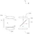
请一并参阅图4,具体地,当选择第一拍摄模式,即全景拍摄模式时,所述处理单元70可控制所述第一反射元件511运动至第一角度方向,例如所述第一反射元件511与水平轴(X轴)之间呈一定角度(例如45度)。同时所述处理单元70控制第二反射元件531运动至第二角度方向,例如所述第二反射元件531与水平轴(X轴)平行设置,并遮蔽其中一个第二镜头,例如第二镜头131A,而另一个未受到第二反射元件531遮蔽的第二镜头131B可另外设置一其他遮蔽组件(如虚线部分),用以遮蔽无须成像的光线,避免影像质量受到影响。如此,所述第一镜头组11中的第一镜头111A及第一镜头111B获取的影像光束可通过所述第一反射元件511的两个反射面分别反射或投射至第一影像感测元件31及第二影像感测元件33。而由于所述第二镜头组13中的第二镜头131A及第二镜头131B获取的影像光束无法形成相应的光学路径,因而无法反射或投射至相应的第一影像感测元件31及第二影像感测元件33。Please refer to FIG. 4 together. Specifically, when the first shooting mode, ie, the panoramic shooting mode, is selected, the
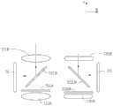
请一并参阅图5,当选择第二拍摄模式时,所述处理单元70可控制所述第一反射元件511运动至第二角度方向,例如所述第一反射元件511与水平轴(X轴)平行设置,并遮蔽其中一个第一镜头,例如第一镜头111A,而另一个未受到第一反射元件511遮蔽的第一镜头111B可另外设置一其他遮蔽组件(如虚线部分),用以遮蔽不会成像的光线,避免影像质量受到影响。同时所述处理单元70控制第二反射元件531运动至第一角度方向,例如所述第二反射元件531与水平轴(X轴)之间呈一定角度(例如45度)。如此,所述第二镜头组13中的第二镜头131A及第二镜头131B获取的影像光束可通过所述第二反射元件531的两个反射面分别反射或投射至第一影像感测元件31及第二影像感测元件33。而由于第一镜头组11中的第一镜头111A及第一镜头111B获取的影像光束无法形成相应的光学路径,因而无法反射或投射至相应的第一影像感测元件31及第二影像感测元件33。Please also refer to FIG. 5 , when the second shooting mode is selected, the
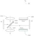
请一并参阅图6,当选择第三拍摄模式时,所述处理单元70可控制所述第一反射元件511运动至第三角度方向,例如所述第一反射元件511与水平轴(X轴)之间呈一定角度(例如135度)。同时所述处理单元70控制第二反射元件531运动至第一角度方向,例如所述第二反射元件531与水平轴(X轴)之间呈一定角度(例如45度)。如此,设置于所述便携式电子装置200的第一表面211的两个镜头,即第一镜头111A及第二镜头131A获取的影像光束可通过所述第一反射元件511及第二反射元件531分别反射或投射至第一影像感测元件31及第二影像感测元件33。而由于位于所述便携式电子装置200的第二表面213的两个镜头,即第一镜头111B及第二镜头131B获取的影像光束无法形成相应的光学路径,因而无法反射或投射至相应的第一影像感测元件31及第二影像感测元件33。Please also refer to FIG. 6 , when the third shooting mode is selected, the
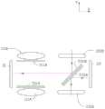
请一并参阅图7,当选择第四拍摄模式时,所述处理单元70可控制所述第一反射元件511运动至第一角度方向,例如所述第一反射元件511与水平轴(X轴)之间呈一定角度(例如45度)。同时所述处理单元70控制第二反射元件531运动至第三角度方向,例如所述第二反射元件531与水平轴(X轴)之间呈一定角度(例如135度)。如此,设置于所述便携式电子装置200的第二表面213的两个镜头,即第一镜头111B及第二镜头131B获取的影像光束可通过所述第一反射元件511及第二反射元件531分别反射或投射至第一影像感测元件31及第二影像感测元件33。而由于位于所述便携式电子装置200的第一表面211的两个镜头,即第一镜头111A及第二镜头131A获取的影像光束无法形成相应的影像路径,因而无法反射或投射至相应的第一影像感测元件31及第二影像感测元件33。Please also refer to FIG. 7 , when the fourth shooting mode is selected, the
可以理解,在其他实施例中,还可根据用户需求,仅选择第一镜头组11或第二镜头组13的其中一个镜头,进而实现其他相应的拍摄模式。It can be understood that in other embodiments, only one lens of the
可以理解,在其他实施例中,所述第一反射单元组51及第二反射单元组53的反射元件的数量不局限于一个,其还可为两个。即所述第一反射单元组51及第二反射单元组53均包括两个反射元件,或者其中一个反射单元组包括一个反射元件,而另外一个反射单元组包括两个反射元件。如此,当需要利用所述反射元件将影像光束反射或投射至相应的影像感测元件时,可利用所述处理单元70控制所述反射元件运动至相应的第一角度方向或第三角度方向,例如与水平轴(X轴)之间呈一定角度(例如45度或135度)。而当无需利用所述反射元件形成对应的光学路径时,可利用所述处理单元70控制该反射元件运动至相应的第二角度方向,例如与水平轴(X轴)平行设置,同时遮蔽相应的镜头,进而有效避免非成像的光线(例如:环境光)进入多镜头系统100而干扰成像品质。It can be understood that, in other embodiments, the number of the reflection elements of the first
具体的,请一并参阅图8,当所述多镜头系统100处于第一拍摄模式时,所述第一反射单元组51中的第一反射元件511A与第一反射元件511B重叠于一起,且均运动至第一角度方向,例如所述第一反射元件511A与第一反射元件511B均与水平轴(X轴)之间呈一定角度(例如45度)。如图8所示,所述第一反射元件511A的定位点为位于该第一反射元件511A的左侧一端,所述第一反射元件511B的定位点为位于该第一反射元件511B的右侧一端。如此以将来自第一镜头111A及第一镜头111B的影像光束分别反射或投射至第一影像感测元件31及第二影像感测元件33。而所述第二反射单元组53中的第二反射元件531A与第二反射元件531B均运动至第二角度方向,即与水平轴(X轴)平行设置,并分别遮蔽相应的第二镜头131A及第二镜头131B,以有效避免非成像的光线(例如:环境光)进入多镜头系统100而干扰成像品质。Specifically, please also refer to FIG. 8 , when the
请一并参阅图9,当所述多镜头系统100处于第二拍摄模式时,所述第二反射单元组53中的第二反射元件531A与第二反射元件531B重叠于一起,且运动至第一角度方向,例如所述第二反射元件531A与第二反射元件531B均与水平轴(X轴)之间呈一定角度(例如45度)。如图9所示,所述第二反射元件531A的定位点为位于该第二反射元件531A的左侧一端,所述第二反射元件531B的定位点为位于该第二反射元件531B的右侧一端,如此以将来自第二镜头131A及第二镜头131B的影像光束分别反射或投射至第一影像感测元件31及第二影像感测元件33。而所述第一反射单元组51中的第一反射元件511A与第一反射元件511B均运动至第二角度方向,例如与水平轴(X轴)平行设置,并分别遮蔽相应的第一镜头111A及第一镜头111B,以有效避免非成像的光线(例如:环境光)进入多镜头系统100而干扰成像品质。Please also refer to FIG. 9 , when the
可以理解,在本实施例中,所述定位点是第一反射元件511A、511B与第二反射元件531A、531B的旋转轴。第一反射元件511A、511B与第二反射元件531A、531B可以其定位点为旋转轴心而转动至所述第一角度方向、第二角度方向或第三角度方向。It can be understood that, in this embodiment, the positioning points are the rotation axes of the first
请一并参阅图10,当所述多镜头系统100处于第三拍摄模式时,所述第一反射单元组51中的第一反射元件511A运动至第三角度方向,例如所述第一反射元件511A与水平轴(X轴)之间呈一定角度(例如135度)。如图10所示,所述第一反射元件511A的定位点为位于该第一反射元件511A的右侧一端,另外一个第一反射元件511B运动至第二角度方向,以遮蔽位于第二表面213的第一镜头111B。所述第二反射单元组53中的其中一个第二反射元件531A运动至第一角度方向,例如所述第二反射元件531A与水平轴(X轴)之间呈一定角度(例如45度)。如图10所示,所述第二反射元件531A的定位点为位于该第二反射元件531A的左侧一端,另外一个第二反射元件531B运动至第二角度方向,以遮蔽位于第二表面213的第二镜头131B。Please also refer to FIG. 10 , when the
请一并参阅图11,当所述多镜头系统100处于第四拍摄模式时,所述第一反射单元组51中的其中一个第一反射元件511B运动至第一角度方向,例如所述第一反射元件511B与水平轴(X轴)之间呈一定角度(例如45度)。所述第一反射元件511B的定位点为位于该第一反射元件511B的右侧一端(如图11所示)。另外一个第一反射元件511A运动至第二角度方向,以遮蔽位于第一表面211的第一镜头111A。所述第二反射单元组53中的其中一个第二反射元件531B运动至第三角度方向,例如所述第二反射元件531B与水平轴(X轴)之间呈一定角度(例如135度)。所述第二反射元件531B的定位点为位于该第二反射元件531B的左侧一端(如图11所示)。另外一个第二反射元件531A运动至第二角度方向,以遮蔽位于第一表面211的第二镜头131A。Please also refer to FIG. 11 , when the
可以理解,在其他实施例中,所述镜头模组10不局限于上述所述的对称式配置方式,其还可采用非对称式的配置方式。例如,请一并参阅图12,所述镜头模组10中的第一镜头111A、第一镜头111B与第二镜头131A、第二镜头131B分别交错设置于所述便携式电子装置200的第一表面211及第二表面213。即该第一镜头111A与第一镜头111B分别设置于所述便携式电子装置200的第一表面211及第二表面213,且两者的光轴互不重叠。所述第二镜头131A及第二镜头131B分别设置于所述便携式电子装置200的第一表面211及第二表面213,且两者的光轴互不重叠。所述处理单元70通过控制所述反射模组50中反射单元的角度方向,同样可实现上述不同的拍摄模式。It can be understood that, in other embodiments, the
例如,请一并参阅图13,当选择第一拍摄模式,即全景拍摄模式时,所述处理单元70可控制所述第一反射元件511及第二反射元件531均运动至第三角度方向,例如所述第一反射元件511及第二反射元件531均与水平轴(X轴)之间呈一定角度(例如135度)。如此,所述第一镜头组11中的第一镜头111A及第一镜头111B获取的影像光束可分别通过所述第一反射元件511及第二反射元件531反射或投射至第一影像感测元件31及第二影像感测元件33。而由于所述第二镜头组13中的第二镜头131A及第二镜头131B获取的影像光束无法形成相应的光学路径,因而无法反射或投射至相应的第一影像感测元件31及第二影像感测元件33。For example, please also refer to FIG. 13 , when the first shooting mode, ie the panoramic shooting mode is selected, the
同样,请一并参阅图14,当选择第二拍摄模式时,所述处理单元70可控制所述第一反射元件511及第二反射元件531均运动至第一角度方向,例如所述第一反射元件511及第二反射元件531均与水平轴(X轴)之间呈一定角度(例如45度)。如此,所述第二镜头组13中的第二镜头131A及第二镜头131B获取的影像光束可分别通过所述第一反射元件511及第二反射元件531反射或投射至第一影像感测元件31及第二影像感测元件33。而由于所述第一镜头组11中的第一镜头111A及第一镜头111B获取的影像光束无法形成相应的光学路径,因而无法反射或投射至相应的第一影像感测元件31及第二影像感测元件33。Similarly, please also refer to FIG. 14 , when the second shooting mode is selected, the
显然,所述镜头模组10通过将镜头采用上述非对称配置方式,可达到最短光学路径的传递,并且可以在没有设置遮蔽的方式下,达到较高的影像成像质量。Obviously, the
可以理解,在其他实施例中,所述镜头模组10不局限于包括两组镜头,其还可为三组或更多组。对应的,所述反射模组50中反射单元的组数可根据镜头模组10中镜头的组数进行调整,例如所述反射模组50中反射单元的组数可以等于镜头模组10中镜头的组数,而所述影像感测模组30中影像感测元件的个数不变,即仍为两个。也就是说,当所述镜头模组10包括多组镜头时,仍只需共用两个影像感测元件即可。It can be understood that, in other embodiments, the
可以理解,在本实施例中,用户可通过显示单元23的用户界面进行设定,以选择相应的拍摄模式,进而触发所述处理单元70根据用户的选择控制反射单元的角度方向,以切换至不同的光学路径,进而选择不同的镜头或镜头组合。It can be understood that, in this embodiment, the user can set through the user interface of the
当然,可以理解的是,在其他实施例中,所述便携式电子装置200还可通过其他的方式触发所述处理单元70,以选择相应的拍摄模式。例如,请再次参阅图3,所述便携式电子装置200还包括感测模组25,所述感测模组25可包括各种类型的感应器,例如加速度感应器、位置感测器、接近感测器等。如此,所述感测模组25可受特定条件触发而启动拍摄模式的侦测,并将侦测到的结果发送至所述处理单元70。如此所述处理单元70可根据上述侦测结果进行判断,并选择相应的影像拍摄模式,同时控制反射单元的角度方向,以切换至不同的光学路径,进而选择不同的镜头或镜头组合。Of course, it can be understood that, in other embodiments, the portable
可以理解,在其他实施例中,所述便携式电子装置200还可包括射频模块、声学模块、存储模块以及电源模块等常用的功能单元,进而实现相应的功能。It can be understood that, in other embodiments, the portable
请一并参阅图15,下面详细介绍所述多镜头系统100的工作原理。Please refer to FIG. 15 together, and the working principle of the
首先便携式电子装置200通过显示单元23或其他方式触发所述处理单元70,以选择相应的拍摄模式,例如可从第一拍摄模式、第二拍摄模式、第三拍摄模式及第四拍摄模式中选择一个作为当前拍摄模式(步骤S1)。接着所述处理单元70根据选择的拍摄模式控制反射单元的角度方向,以切换至不同的光学路径,进而选择不同的镜头或镜头组合(步骤S2)。例如,当选择第一拍摄模式,即全景拍摄模式时,所述处理单元70可控制所述第一反射元件511运动至第一角度方向,例如所述第一反射元件511与水平轴(X轴)之间呈一定角度(例如45度)。同时所述处理单元70控制第二反射元件531运动至第二角度方向,例如所述第二反射元件531与水平轴(X轴)平行设置。如此,所述第一镜头组11中的第一镜头111A及第一镜头111B获取的影像光束可通过所述第一反射元件511的两个反射面分别反射或投射至第一影像感测元件31及第二影像感测元件33。而由于所述第二镜头组13中的第二镜头131A及第二镜头131B获取的影像光束无法形成相应的光学路径,因而无法反射或投射至相应的第一影像感测元件31及第二影像感测元件33。最后,所述第一影像感测元件31及第二影像感测元件33可配合选取的镜头或镜头组合,例如第一镜头111A及第一镜头111B拍摄相应的画面,并将拍摄获得的画面数据均传送至所述处理单元70(步骤S3)。所述处理单元70再对接收到的画面数据进行处理,例如进行影像拼接、影像融合等,进而获得符合需求的影像,例如全景影像(步骤S4)。First, the portable
上述多镜头系统100通过在便携式电子装置200上设置包括多组镜头的镜头模组10,并设置相应的反射模组50。如此,所述处理单元70可根据不同的需求选择相应的拍摄模式,并根据选择的拍摄模式控制所述反射模组50中反射单元的角度方向,进而调整反射单元的光学路径,以选择不同的镜头或镜头组合。上述多镜头系统100的结构简单,且可适用多种不同的拍摄模式,例如全景拍摄模式、普通的双镜头拍摄模式等等,具有较强的实用性。In the above-mentioned
综上所述,尽管为说明目的已经公开了本发明的优选实施例,然而,本发明不只局限于如上所述的实施例,在不超出本发明基本技术思想的范畴内,相关行业的技术人员可对其进行多种变形及应用。In conclusion, although the preferred embodiments of the present invention have been disclosed for the purpose of illustration, the present invention is not limited to the above-mentioned embodiments. Various modifications and applications are possible.
Claims (11)
Translated fromChinesePriority Applications (2)
| Application Number | Priority Date | Filing Date | Title |
|---|---|---|---|
| CN201610159721.6ACN107219710B (en) | 2016-03-21 | 2016-03-21 | Multi-lens system and portable electronic device having the same |
| US15/458,161US10536634B2 (en) | 2016-03-21 | 2017-03-14 | Multiple lens system and portable electronic device employing the same |
Applications Claiming Priority (1)
| Application Number | Priority Date | Filing Date | Title |
|---|---|---|---|
| CN201610159721.6ACN107219710B (en) | 2016-03-21 | 2016-03-21 | Multi-lens system and portable electronic device having the same |
Publications (2)
| Publication Number | Publication Date |
|---|---|
| CN107219710A CN107219710A (en) | 2017-09-29 |
| CN107219710Btrue CN107219710B (en) | 2020-12-08 |
Family
ID=59847260
Family Applications (1)
| Application Number | Title | Priority Date | Filing Date |
|---|---|---|---|
| CN201610159721.6AActiveCN107219710B (en) | 2016-03-21 | 2016-03-21 | Multi-lens system and portable electronic device having the same |
Country Status (2)
| Country | Link |
|---|---|
| US (1) | US10536634B2 (en) |
| CN (1) | CN107219710B (en) |
Families Citing this family (13)
| Publication number | Priority date | Publication date | Assignee | Title |
|---|---|---|---|---|
| US10200672B2 (en)* | 2016-08-17 | 2019-02-05 | Nextvr Inc. | Methods and apparatus for capturing images of an environment |
| CN107172336B (en)* | 2017-06-26 | 2019-01-11 | 维沃移动通信有限公司 | A kind of camera module, mobile terminal and its control method |
| US20200012069A1 (en)* | 2018-07-06 | 2020-01-09 | Fuzhou Rockchip Electronics Co., Ltd. | Structures and Methods for Capturing Images by a Portable Electronic Device with a Linear Movement Switching Mechanism |
| CN109379455B (en)* | 2018-09-27 | 2021-07-30 | 维沃移动通信有限公司 | A kind of image recognition method and device based on mobile terminal |
| US11653097B2 (en) | 2018-10-12 | 2023-05-16 | Samsung Electronics Co., Ltd. | Method and electronic device for switching between first lens and second lens |
| CN117336602A (en)* | 2018-10-12 | 2024-01-02 | 三星电子株式会社 | Method and electronic device for switching between first lens and second lens |
| CN109769086A (en)* | 2019-02-28 | 2019-05-17 | Oppo广东移动通信有限公司 | Camera module and terminal |
| KR102099232B1 (en)* | 2019-07-03 | 2020-04-08 | 주식회사 레티널 | Camera module using small reflective surface and optical device for augmented reality using the camera module |
| WO2021128559A1 (en)* | 2019-12-23 | 2021-07-01 | 南昌欧菲光电技术有限公司 | Periscope lens module, periscope camera device, and intelligent terminal |
| KR102286945B1 (en)* | 2020-01-31 | 2021-08-09 | 주식회사 가치소프트 | Image capturing system and method thereof |
| US11277551B2 (en) | 2020-04-03 | 2022-03-15 | Qualcomm Incorporated | Multiple optical path imaging techniques and shared emitter for active depth sensing techniques |
| KR102345118B1 (en) | 2020-07-24 | 2021-12-30 | 삼성전기주식회사 | A Camera Module and Portable Terminal having the Same |
| US20250104473A1 (en)* | 2022-01-11 | 2025-03-27 | Nec Corporation | Imaging system, imaging method, and non-transitory recording medium |
Citations (3)
| Publication number | Priority date | Publication date | Assignee | Title |
|---|---|---|---|---|
| CN1837880A (en)* | 2005-03-25 | 2006-09-27 | 鸿富锦精密工业(深圳)有限公司 | Lens module |
| CN101833157A (en)* | 2009-03-13 | 2010-09-15 | 鸿富锦精密工业(深圳)有限公司 | Camera module |
| CN101852979A (en)* | 2009-03-30 | 2010-10-06 | 鸿富锦精密工业(深圳)有限公司 | panoramic camera |
Family Cites Families (29)
| Publication number | Priority date | Publication date | Assignee | Title |
|---|---|---|---|---|
| FR1584770A (en)* | 1968-07-12 | 1970-01-02 | ||
| US3626094A (en)* | 1969-01-08 | 1971-12-07 | Electronic Systems Dev Inc | Message display system for television |
| GB1301554A (en)* | 1970-07-14 | 1972-12-29 | ||
| US3891303A (en)* | 1972-08-14 | 1975-06-24 | Joaquin Gomez Barquero | Combined system of optical devices for photography and stereoscopic vision |
| US4303316A (en)* | 1978-10-19 | 1981-12-01 | Mcelveen Robert H | Process for recording visual scenes for reproduction in stereopsis |
| DE3374448D1 (en)* | 1982-04-07 | 1987-12-17 | Street Graham S B | Method and apparatus for use in producing autostereoscopic images |
| US4574197A (en)* | 1983-03-24 | 1986-03-04 | Hughes Aircraft Company | Dual field of view sensor |
| US5204922A (en)* | 1991-10-22 | 1993-04-20 | Puritan-Bennett Corporation | Optical signal channel selector |
| US5734477C1 (en)* | 1996-05-22 | 2001-12-25 | Must System Inc | Optical device having multilenses |
| US6529640B1 (en)* | 1998-06-09 | 2003-03-04 | Nikon Corporation | Image processing apparatus |
| JP4994556B2 (en)* | 2000-03-17 | 2012-08-08 | ストラテジック パテント アクイジションズ エルエルシー | High clarity lens system |
| JP3905736B2 (en)* | 2001-10-12 | 2007-04-18 | ペンタックス株式会社 | Stereo image pickup device and automatic congestion adjustment device |
| US7542781B2 (en)* | 2003-06-30 | 2009-06-02 | Casio Computer Co., Ltd. | Handheld electronic apparatus |
| KR20050090780A (en)* | 2004-03-10 | 2005-09-14 | 삼성전자주식회사 | Image photographing apparatus |
| US7920182B2 (en)* | 2005-04-29 | 2011-04-05 | Eliezer Jacob | Digital camera with non-uniform image resolution |
| JP4624245B2 (en)* | 2005-11-29 | 2011-02-02 | イーストマン コダック カンパニー | Imaging device |
| US7676146B2 (en)* | 2007-03-09 | 2010-03-09 | Eastman Kodak Company | Camera using multiple lenses and image sensors to provide improved focusing capability |
| CN101430389B (en)* | 2007-11-06 | 2010-04-07 | 鸿富锦精密工业(深圳)有限公司 | Membrane structure of blue beam splitter |
| US7826121B2 (en)* | 2008-09-15 | 2010-11-02 | Texas Instruments Incorporated | Use of an angle-selective retro-reflector to recapture off-state energy |
| CN101521745B (en) | 2009-04-14 | 2011-04-13 | 王广生 | Multi-lens optical center superposing type omnibearing shooting device and panoramic shooting and retransmitting method |
| US20120154549A1 (en)* | 2010-12-16 | 2012-06-21 | An Wenge David | Adapter and corresponding methods for adding 3D function to a 2D digital camera |
| US10274718B2 (en)* | 2012-01-31 | 2019-04-30 | Siemens Energy, Inc. | Single-axis inspection scope with anti-rotation extension and method for internal inspection of power generation machinery |
| JP2013238848A (en)* | 2012-04-20 | 2013-11-28 | Hoya Corp | Imaging apparatus |
| JP6195334B2 (en)* | 2012-08-30 | 2017-09-13 | キヤノン株式会社 | Imaging apparatus, imaging method, and program |
| DE102012019472B4 (en)* | 2012-09-28 | 2023-05-04 | Carl Zeiss Microscopy Gmbh | Optical filter device, in particular for microscopes, and microscope |
| US20140218587A1 (en)* | 2013-02-07 | 2014-08-07 | Motorola Mobility Llc | Double sided camera module |
| TW201513660A (en)* | 2013-09-25 | 2015-04-01 | Univ Nat Central | Image-capturing system with dual lenses |
| WO2017119555A1 (en)* | 2016-01-08 | 2017-07-13 | Lg Electronics Inc. | Portable camera |
| US20170285238A1 (en)* | 2016-03-31 | 2017-10-05 | Intel Corporation | Optical isolator |
- 2016
- 2016-03-21CNCN201610159721.6Apatent/CN107219710B/enactiveActive
- 2017
- 2017-03-14USUS15/458,161patent/US10536634B2/enactiveActive
Patent Citations (3)
| Publication number | Priority date | Publication date | Assignee | Title |
|---|---|---|---|---|
| CN1837880A (en)* | 2005-03-25 | 2006-09-27 | 鸿富锦精密工业(深圳)有限公司 | Lens module |
| CN101833157A (en)* | 2009-03-13 | 2010-09-15 | 鸿富锦精密工业(深圳)有限公司 | Camera module |
| CN101852979A (en)* | 2009-03-30 | 2010-10-06 | 鸿富锦精密工业(深圳)有限公司 | panoramic camera |
Also Published As
| Publication number | Publication date |
|---|---|
| US10536634B2 (en) | 2020-01-14 |
| US20170272650A1 (en) | 2017-09-21 |
| CN107219710A (en) | 2017-09-29 |
Similar Documents
| Publication | Publication Date | Title |
|---|---|---|
| CN107219710B (en) | Multi-lens system and portable electronic device having the same | |
| JP6700345B2 (en) | Multi-camera system using folded optics | |
| US7643749B2 (en) | Camera module | |
| CN105959525B (en) | A kind of filming control method, camera module and mobile terminal | |
| CN104519265B (en) | A kind of terminal device and image capture method | |
| CN111901503A (en) | Camera module, terminal equipment, imaging method and imaging device | |
| US10616503B2 (en) | Communication apparatus and optical device thereof | |
| KR20060049992A (en) | Forbidden Panoramic Camera System | |
| CN104980541A (en) | Camera module and mobile terminal | |
| CN106462050A (en) | Wide Field of View Array Camera for Hemispherical and Spherical Imaging | |
| CN109313374B (en) | Portable device with adjustable optical means | |
| CN110266922A (en) | Camera modules and electronic equipment | |
| EP4006623A1 (en) | Optical anti-shake apparatus and control method | |
| KR102606609B1 (en) | Camera module, terminal device, imaging method and imaging device | |
| WO2016165644A1 (en) | Panoramic image acquisition device | |
| CN206743363U (en) | A kind of binocular head device and a kind of image capturing device | |
| CN106556961A (en) | Image pickup apparatus and method of operating the same | |
| JP2015171116A (en) | Display device of camera | |
| CN113874772A (en) | Optical system, electronic equipment and display device | |
| TWI578778B (en) | Multiple lens system and portable electronic device with same | |
| CN106713898B (en) | Three-lens panoramic 3D camera | |
| JP5234490B2 (en) | Stereo image forming apparatus | |
| CN103428414A (en) | Camera device for portable terminal | |
| CN204269904U (en) | Lens assembly and imaging module with lens assembly | |
| US20170094150A1 (en) | Image capture system and focusing method thereof |
Legal Events
| Date | Code | Title | Description |
|---|---|---|---|
| PB01 | Publication | ||
| PB01 | Publication | ||
| SE01 | Entry into force of request for substantive examination | ||
| SE01 | Entry into force of request for substantive examination | ||
| GR01 | Patent grant | ||
| GR01 | Patent grant |