CN107214699B - Motion control method of mechanical arm, microcontroller and storage medium - Google Patents
Motion control method of mechanical arm, microcontroller and storage mediumDownload PDFInfo
- Publication number
- CN107214699B CN107214699BCN201710379367.2ACN201710379367ACN107214699BCN 107214699 BCN107214699 BCN 107214699BCN 201710379367 ACN201710379367 ACN 201710379367ACN 107214699 BCN107214699 BCN 107214699B
- Authority
- CN
- China
- Prior art keywords
- control device
- microcontroller
- motion
- control
- motion data
- Prior art date
- Legal status (The legal status is an assumption and is not a legal conclusion. Google has not performed a legal analysis and makes no representation as to the accuracy of the status listed.)
- Active
Links
- 230000033001locomotionEffects0.000titleclaimsabstractdescription324
- 238000000034methodMethods0.000titleclaimsabstractdescription46
- 230000007246mechanismEffects0.000claimsdescription47
- 238000006243chemical reactionMethods0.000claimsdescription18
- 238000004590computer programMethods0.000claimsdescription11
- 230000008569processEffects0.000claimsdescription9
- 238000001514detection methodMethods0.000claimsdescription6
- 238000004891communicationMethods0.000claimsdescription4
- 238000010586diagramMethods0.000description12
- 238000012544monitoring processMethods0.000description11
- 230000001133accelerationEffects0.000description6
- 230000006870functionEffects0.000description6
- 230000009471actionEffects0.000description4
- 230000008878couplingEffects0.000description3
- 238000010168coupling processMethods0.000description3
- 238000005859coupling reactionMethods0.000description3
- 230000000694effectsEffects0.000description3
- 238000012545processingMethods0.000description3
- 230000003993interactionEffects0.000description2
- 230000036544postureEffects0.000description2
- 210000000078clawAnatomy0.000description1
- 230000007547defectEffects0.000description1
- 230000026058directional locomotionEffects0.000description1
- 238000009434installationMethods0.000description1
- 238000010147laser engravingMethods0.000description1
- 238000013507mappingMethods0.000description1
- 238000012986modificationMethods0.000description1
- 230000004048modificationEffects0.000description1
- 230000003287optical effectEffects0.000description1
- 238000010422paintingMethods0.000description1
- 230000002093peripheral effectEffects0.000description1
- 230000001960triggered effectEffects0.000description1
Images


Classifications
- B—PERFORMING OPERATIONS; TRANSPORTING
- B25—HAND TOOLS; PORTABLE POWER-DRIVEN TOOLS; MANIPULATORS
- B25J—MANIPULATORS; CHAMBERS PROVIDED WITH MANIPULATION DEVICES
- B25J9/00—Programme-controlled manipulators
- B25J9/16—Programme controls
- B25J9/1602—Programme controls characterised by the control system, structure, architecture
- B25J9/161—Hardware, e.g. neural networks, fuzzy logic, interfaces, processor
- B—PERFORMING OPERATIONS; TRANSPORTING
- B25—HAND TOOLS; PORTABLE POWER-DRIVEN TOOLS; MANIPULATORS
- B25J—MANIPULATORS; CHAMBERS PROVIDED WITH MANIPULATION DEVICES
- B25J13/00—Controls for manipulators
- B25J13/06—Control stands, e.g. consoles, switchboards
- B25J13/065—Control stands, e.g. consoles, switchboards comprising joy-sticks
- B—PERFORMING OPERATIONS; TRANSPORTING
- B25—HAND TOOLS; PORTABLE POWER-DRIVEN TOOLS; MANIPULATORS
- B25J—MANIPULATORS; CHAMBERS PROVIDED WITH MANIPULATION DEVICES
- B25J9/00—Programme-controlled manipulators
- B25J9/16—Programme controls
- B25J9/1656—Programme controls characterised by programming, planning systems for manipulators
- B25J9/1664—Programme controls characterised by programming, planning systems for manipulators characterised by motion, path, trajectory planning
Landscapes
- Engineering & Computer Science (AREA)
- Robotics (AREA)
- Mechanical Engineering (AREA)
- Automation & Control Theory (AREA)
- Physics & Mathematics (AREA)
- Artificial Intelligence (AREA)
- Evolutionary Computation (AREA)
- Fuzzy Systems (AREA)
- Mathematical Physics (AREA)
- Software Systems (AREA)
- Manipulator (AREA)
- Position Input By Displaying (AREA)
Abstract
Description
Translated fromChinese技术领域technical field
本发明涉及机器人技术领域,尤其涉及机械臂的运动控制方法、微控制器和存储介质。The present invention relates to the technical field of robotics, in particular to a motion control method, a microcontroller and a storage medium of a robotic arm.
背景技术Background technique
随着产业升级和企业技术进步的加快,机械臂成为了机器人技术领域中被得到广泛实际应用的自动化机械装置,此类机械臂具有多自由度,允许在二维或三维空间进行运动,通过接收控制指令以完成各种作业。With the acceleration of industrial upgrading and technological progress of enterprises, the robotic arm has become an automated mechanical device that has been widely used in the field of robotics. This type of robotic arm has multiple degrees of freedom and allows movement in two-dimensional or three-dimensional space. Control commands to complete various jobs.
目前,对机械臂的运动控制主要通过人机交互实现,在现有技术中,最常见的运动控制方式包括在PC端或移动端通过应用界面进行控制。比如,用户如果想要控制机械臂往A方向以B速度移动,则用户首先需要在应用界面上找到控制机械臂的运动方向的第一控制按键,以及控制机械臂的运动速度的第二控制按键,然后,用户触发第一控制按键设定运动方向为A,并且触发第二控制按键设定运动速度为B,最后,根据上述设定的参数生成并发出控制指令,实现对机械臂的运动方向和运动速度的控制。可见,该运动控制方式主要存在以下缺陷:用户通过PC端或移动端上的应用界面对机械臂的运动进行间接控制,这在一定程度上降低了用户对机械臂的运动控制效率。At present, the motion control of the robotic arm is mainly realized through human-computer interaction. In the prior art, the most common motion control method includes control through an application interface on a PC or mobile terminal. For example, if the user wants to control the robotic arm to move in the A direction at the speed B, the user first needs to find the first control button for controlling the moving direction of the robotic arm and the second control button for controlling the moving speed of the robotic arm on the application interface , and then, the user triggers the first control button to set the movement direction to A, and triggers the second control button to set the movement speed to B. Finally, the control command is generated and issued according to the parameters set above to realize the movement direction of the robotic arm. and movement speed control. It can be seen that this motion control method mainly has the following defects: the user indirectly controls the motion of the robotic arm through the application interface on the PC terminal or the mobile terminal, which reduces the user's motion control efficiency of the robotic arm to a certain extent.
发明内容SUMMARY OF THE INVENTION
本发明实施例提供了一种机械臂的运动控制方法、微控制器和存储介质,对机械臂旋转轴的运动控制主要通过人机交互实现,用户不需要点击应用界面上代表相应控制指令的控制按键来触发控制指令,便可实现对机械臂的运动方向和运动速度的控制,能够建立起控制设备上移动部件与机械臂运动的直观联系,提升机械臂的运动控制效率。The embodiments of the present invention provide a motion control method, a microcontroller and a storage medium for a robotic arm. The motion control of the rotating axis of the robotic arm is mainly realized through human-computer interaction, and the user does not need to click the control representing the corresponding control instruction on the application interface. By pressing the button to trigger the control command, the movement direction and speed of the robot arm can be controlled, which can establish an intuitive connection between the moving parts on the control device and the movement of the robot arm, and improve the movement control efficiency of the robot arm.
本发明实施例提供的一种机械臂的运动控制方法,应用于一种设有微控制器的机械臂,所述运动控制方法包括:A motion control method for a robotic arm provided by an embodiment of the present invention is applied to a robotic arm provided with a microcontroller, and the motion control method includes:
所述微控制器获取来自控制设备的所述控制设备上移动部件的移动方向和在所述移动方向上的移动距离,所述移动方向和所述移动距离为所述控制设备通过对所述移动部件的移动情况进行检测得到;The microcontroller acquires the movement direction and the movement distance of the moving part on the control device from the control device, and the movement direction and the movement distance are obtained by the control device by adjusting the movement to the movement direction. The movement of the parts is detected;
所述微控制器将所述移动部件的移动方向转换为所述机械臂的运动方向;The microcontroller converts the moving direction of the moving part into the moving direction of the mechanical arm;
所述微控制器根据所述移动部件的所述移动距离确定所述机械臂在所述运动方向上的运动速度;The microcontroller determines the moving speed of the mechanical arm in the moving direction according to the moving distance of the moving part;
所述微控制器生成第一运动数据,所述第一运动数据用于控制所述机械臂以所述运动速度沿所述运动方向运动;The microcontroller generates first motion data, where the first motion data is used to control the robotic arm to move along the motion direction at the motion speed;
所述微控制器将所述第一运动数据发送至所述机械臂的驱动扩展板。The microcontroller sends the first motion data to the drive expansion board of the robotic arm.
本发明实施例提供的一种设于机械臂上的微控制器,包括:A microcontroller provided on a robotic arm provided by an embodiment of the present invention includes:
移动检测模块,用于获取来自控制设备的所述控制设备上移动部件的移动方向和在所述移动方向上的移动距离,所述移动方向和所述移动距离为所述控制设备通过对所述移动部件的移动情况进行检测得到;The movement detection module is used to obtain the movement direction and the movement distance in the movement direction of the moving part on the control device from the control device, the movement direction and the movement distance are obtained by the control device by The movement of the moving parts is detected;
运动方向转换模块,用于将所述移动部件的移动方向转换为机械臂的运动方向;a movement direction conversion module, which is used to convert the movement direction of the moving part into the movement direction of the mechanical arm;
运动速度转换模块,用于根据所述移动部件的所述移动距离确定所述机械臂在所述运动方向上的运动速度;a movement speed conversion module, configured to determine the movement speed of the mechanical arm in the movement direction according to the movement distance of the moving part;
第一运动数据生成模块,用于生成第一运动数据,所述第一运动数据用于控制所述机械臂以所述运动速度沿所述运动方向运动;a first motion data generating module, configured to generate first motion data, where the first motion data is used to control the robotic arm to move along the motion direction at the motion speed;
第一运动数据发送模块,用于将所述第一运动数据发送至所述机械臂的驱动扩展板。A first motion data sending module, configured to send the first motion data to the drive expansion board of the robotic arm.
从以上技术方案可以看出,本发明实施例具有以下优点:As can be seen from the above technical solutions, the embodiments of the present invention have the following advantages:
本发明实施例中,首先,设于机械臂上的微控制器获取来自控制设备的所述控制设备上移动部件的移动方向和在所述移动方向上的移动距离,所述移动方向和所述移动距离为所述控制设备通过对所述移动部件的移动情况进行检测得到;然后,将所述移动部件的移动方向转换为机械臂的运动方向;根据所述移动部件的所述移动距离确定所述机械臂在所述运动方向上的运动速度;接着,生成第一运动数据,所述第一运动数据用于控制所述机械臂以所述运动速度沿所述运动方向运动;最后,将所述第一运动数据发送至所述机械臂的驱动扩展板。在本发明实施例中,通过预先建立控制设备的移动部件与机械臂之间运动坐标系的转换关系,将移动部件的移动情况转换成对机械臂进行控制的第一运动数据,从而建立起控制设备上移动部件与机械臂运动的直观联系,提升了机械臂的运动控制效率。In this embodiment of the present invention, first, the microcontroller provided on the robotic arm acquires the moving direction and the moving distance in the moving direction of the moving component on the control device from the control device, the moving direction and the moving distance in the moving direction are obtained. The moving distance is obtained by the control device by detecting the movement of the moving part; then, the moving direction of the moving part is converted into the moving direction of the mechanical arm; the moving distance of the moving part is determined. the movement speed of the robotic arm in the movement direction; then, generate first movement data, and the first movement data is used to control the robot arm to move along the movement direction at the movement speed; finally, the The first motion data is sent to the drive expansion board of the robotic arm. In the embodiment of the present invention, by pre-establishing the conversion relationship between the moving coordinate system of the moving part of the control device and the manipulator, the movement of the moving part is converted into the first motion data for controlling the manipulator, thereby establishing the control The intuitive connection between the moving parts on the equipment and the motion of the robotic arm improves the motion control efficiency of the robotic arm.
附图说明Description of drawings
图1a为第一型号机械臂的正视结构示意图;Fig. 1a is the front view structure schematic diagram of the first type mechanical arm;
图1b和图1c为第一型号机械臂在两个不同姿态下的俯视结构示意图;Fig. 1b and Fig. 1c are schematic top-view structural diagrams of the first model manipulator in two different postures;
图1d为第二型号机械臂的正视结构示意图;Fig. 1d is a schematic view of the front structure of the second type of mechanical arm;
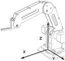
图1e为标有三维坐标系的一种机械臂的立体结构示意图;Fig. 1e is a three-dimensional schematic diagram of a mechanical arm marked with a three-dimensional coordinate system;
图1f为本发明实施例提供的机械臂运动控制系统的结构框图;1f is a structural block diagram of a robotic arm motion control system provided by an embodiment of the present invention;
图1g为本发明实施例中一种机械臂的结构示意图;1g is a schematic structural diagram of a mechanical arm in an embodiment of the present invention;
图2a为标有三维坐标系的一种3D鼠标的立体结构示意图;Figure 2a is a schematic diagram of a three-dimensional structure of a 3D mouse marked with a three-dimensional coordinate system;
图2b为图2a所示3D鼠标的俯视图;Fig. 2b is a top view of the 3D mouse shown in Fig. 2a;
图3为本发明实施例中一种机械臂的运动控制方法一个实施例的流程图;3 is a flowchart of an embodiment of a method for controlling motion of a robotic arm in an embodiment of the present invention;
图4为本发明实施例中一种机械臂的运动控制方法另一个实施例的流程图;4 is a flowchart of another embodiment of a method for controlling motion of a robotic arm in an embodiment of the present invention;
图5为本发明实施例中一种机械臂的运动控制方法对执行机构进行运动控制的具体流程图;5 is a specific flow chart of a motion control method for a robotic arm performing motion control on an actuator in an embodiment of the present invention;
图6为本发明实施例中一种设于机械臂上的微控制器一个实施例结构图;6 is a structural diagram of an embodiment of a microcontroller disposed on a robotic arm in an embodiment of the present invention;
图7为本发明一实施例提供的微控制器的示意图。FIG. 7 is a schematic diagram of a microcontroller according to an embodiment of the present invention.
具体实施方式Detailed ways
本发明实施例提供了一种机械臂的运动控制方法、微控制器和存储介质,用于应用界面中的界面按键无法与机械臂的运动方向直观对应的问题。Embodiments of the present invention provide a motion control method, a microcontroller and a storage medium for a robotic arm, which are used for the problem that the interface keys in the application interface cannot intuitively correspond to the moving direction of the robotic arm.
为使得本发明的发明目的、特征、优点能够更加的明显和易懂,下面将结合本发明实施例中的附图,对本发明实施例中的技术方案进行清楚、完整地描述,显然,下面所描述的实施例仅仅是本发明一部分实施例,而非全部的实施例。基于本发明中的实施例,本领域普通技术人员在没有做出创造性劳动前提下所获得的所有其它实施例,都属于本发明保护的范围。In order to make the purpose, features and advantages of the present invention more obvious and understandable, the technical solutions in the embodiments of the present invention will be clearly and completely described below with reference to the accompanying drawings in the embodiments of the present invention. Obviously, the following The described embodiments are only some, but not all, embodiments of the present invention. Based on the embodiments of the present invention, all other embodiments obtained by those of ordinary skill in the art without creative efforts shall fall within the protection scope of the present invention.
首先,图1f示出了本发明实施例提供的机械臂运动控制系统的结构框图,为了便于说明,仅示出与本实施例相关的部分。First, FIG. 1f shows a structural block diagram of a robotic arm motion control system provided by an embodiment of the present invention. For convenience of description, only the part related to this embodiment is shown.
参照图1f,在本发明实施例中,机械臂运动控制系统可以由控制设备、微控制器、驱动扩展板和机械臂本体组成,其中,微控制器、驱动扩展板和机械臂本体均设于机械臂上;而控制设备可以安装在所述机械臂上,也可以作为机械臂的外设通过有线或无线的方式与所述机械臂上的微控制器通信连接。特别地,在一个应用场景下,本发明实施例提供的一种机械臂的结构如图1g所示。优选地,微控制器在机械臂上的安装位置可以有以下两种方式。第一种方式,该微控制器可以安装在所述机械臂底座a的主控电路板上,通过所述主控电路板与所述控制设备b以及所述机械臂电气连接。第二种方式,所述微控制器可以设于所述控制设备b上,所述控制设备b安装在所述机械臂上;所述微控制器与所述机械臂上的驱动扩展板通信连接。该机械臂运动控制系统在工作时,微控制器对控制设备的转动事件、移动事件和/或触发事件进行采集,以获取到控制设备的操作数据,并根据操作数据生成对应的运动数据,然后将生成的运动数据发送给驱动扩展板,由驱动扩展板驱动机械臂本体依照该运动数据进行运动,由此实现通过控制设备对机械臂进行运动控制。可见,本实施例中通过微控制器直接作为事件转换和运动数据生成的执行主体,可以直接将生成的运动数据交给驱动扩展板执行,相比现有技术通过控制指令来控制机械臂的方式,由于无需消耗额外的资源对指令进行解析,因此对机械臂的控制更加高效、准确。Referring to FIG. 1f, in the embodiment of the present invention, the robotic arm motion control system may be composed of a control device, a microcontroller, a drive expansion board, and a robotic arm body, wherein the microcontroller, the drive expansion board, and the robotic arm body are all located in On the mechanical arm; and the control device can be installed on the mechanical arm, and can also be used as a peripheral device of the mechanical arm to communicate with the microcontroller on the mechanical arm in a wired or wireless manner. In particular, in an application scenario, the structure of a robotic arm provided by an embodiment of the present invention is shown in FIG. 1g. Preferably, the installation position of the microcontroller on the robotic arm can be in the following two ways. In a first manner, the microcontroller can be installed on the main control circuit board of the robot arm base a, and is electrically connected to the control device b and the robot arm through the main control circuit board. In the second way, the microcontroller can be set on the control device b, and the control device b is installed on the robotic arm; the microcontroller is connected in communication with the drive expansion board on the robotic arm . When the robotic arm motion control system is working, the microcontroller collects the rotation events, movement events and/or trigger events of the control device to obtain the operation data of the control device, and generates corresponding motion data according to the operation data, and then The generated motion data is sent to the drive expansion board, and the drive expansion board drives the manipulator body to move according to the motion data, thereby realizing the motion control of the manipulator through the control device. It can be seen that in this embodiment, the microcontroller is directly used as the execution body for event conversion and motion data generation, and the generated motion data can be directly handed over to the drive expansion board for execution. , since there is no need to consume additional resources to parse the instructions, the control of the robotic arm is more efficient and accurate.
另外,本发明实施例中,控制设备可以具体为鼠标或摇杆控制器。其中,鼠标可以为普通鼠标或3D鼠标。In addition, in this embodiment of the present invention, the control device may specifically be a mouse or a joystick controller. The mouse may be a normal mouse or a 3D mouse.
如图2a、2b所示,图2a为3D鼠标的立体示意图,图2b为3D鼠标的俯视图,其中,02为3D鼠标上的弹性结构。当控制设备为3D鼠标时,3D鼠标(例如Space Navigate)上配置的弹性结构02可旋转、拧动,该弹性结构 02在旋转、拧动时可作为控制设备的旋钮。另外,该弹性结构02还可以被提起或按下,因此该弹性结构02在用于提起或按下时,可作为控制设备在垂直方向上的移动部件。如图2b所示,3D鼠标本身还可以在平面上滑动,在3D 鼠标本身滑动时,3D鼠标可以输出滑动过程中的移动方向和移动距离,因此, 3D鼠标本身可作为控制设备在水平方向上的移动部件。另外,对于部分型号的3D鼠标,其上还可以配置一个以上按键,这些按键可以作为控制设备的触发部件。同理,当控制设备为普通鼠标时,其大部分控制部件与3D鼠标的类似,另外需要为普通鼠标额外配置一个旋钮作为控制部件的旋钮使用。As shown in Figures 2a and 2b, Figure 2a is a three-dimensional schematic diagram of a 3D mouse, and Figure 2b is a top view of the 3D mouse, wherein 02 is an elastic structure on the 3D mouse. When the control device is a 3D mouse, the
而当控制设备为摇杆控制器时,摇杆控制器上配置的旋钮或者用于绕圆周进行摇动操作的摇杆,可以看作是控制设备的旋钮。另外,部分型号的摇杆控制器上配置的弹性结构可被提起或按下,因此该弹性结构在用于提起或按下时,可作为控制设备在垂直方向上的移动部件。摇杆控制器上的摇杆可以往一个水平面的各个方向摇动,在摇杆摇动时,摇杆控制器可以输出遥控过程中的摇动方向和摇动距离,因此,摇杆控制器的摇杆可以作为控制设备在水平方向上的移动部件。另外,对于大多数摇杆控制器来说,其上配置有一个以上按键,这些按键可以作为控制设备的触发部件。When the control device is a joystick controller, the knob configured on the joystick controller or the joystick used for shaking operation around the circumference can be regarded as the knob of the control device. In addition, the elastic structure configured on some models of the joystick controller can be lifted or pressed, so when the elastic structure is used for lifting or pressing, it can be used as a moving part of the control device in the vertical direction. The joystick on the joystick controller can be shaken in all directions on a horizontal plane. When the joystick is shaken, the joystick controller can output the shaking direction and shaking distance during the remote control process. Therefore, the joystick of the joystick controller can be used as a Controls the moving parts of the device in the horizontal direction. In addition, for most joystick controllers, there are more than one buttons configured on them, and these buttons can be used as trigger parts of the control device.
由上述内容可知,本发明实施例中的控制设备具有多种选择。在下述内容中,为便于描述,仅以3D鼠标作为控制设备为例进行说明。It can be known from the above content that the control device in the embodiment of the present invention has various options. In the following content, for the convenience of description, only a 3D mouse is used as an example for description.
基于图1f所示的系统结构,图3示出了本发明实施例提供的机械臂的运动控制方法的实现流程,详述如下:Based on the system structure shown in FIG. 1f, FIG. 3 shows the implementation process of the motion control method of the robotic arm provided by the embodiment of the present invention, and the details are as follows:
步骤301、所述微控制器获取来自控制设备的所述控制设备上移动部件的移动方向和在所述移动方向上的移动距离,所述移动方向和所述移动距离为所述控制设备通过对所述移动部件的移动情况进行检测得到;Step 301: The microcontroller obtains the movement direction and the movement distance of the moving part on the control device from the control device, and the movement direction and the movement distance are obtained by the control device through pairing. The movement of the moving part is detected and obtained;
在本实施例中,控制设备为3D鼠标,实现的是对3D鼠标运动数据的采集,微控制器通过对3D鼠标事件进行监听,获取到3D鼠标移动部件的移动方向及移动部件在该移动方向上的移动距离。其中,所述移动部件,可以为 3D鼠标本体或者弹性结构(用于提起或按下时),若移动部件为3D鼠标本体,由于3D鼠标本体可以在水平面上进行如图2b所示的X轴方向和Y轴方向的移动,因此,需要分别获取到3D鼠标本体在上述两个轴向方向上的移动距离;若移动部件为3D鼠标的弹性结构,由于弹性结构可以在垂直方向上被提起或按下,因此,弹性结构可以在垂直方向上进行如图2a所示的Z轴方向的移动,并需要获取到该弹性结构在垂直方向上的移动距离。In this embodiment, the control device is a 3D mouse, which realizes the collection of 3D mouse motion data. The microcontroller monitors the 3D mouse events to obtain the moving direction of the 3D mouse moving part and the moving direction of the moving part in the moving direction. the moving distance on . Wherein, the moving part can be a 3D mouse body or an elastic structure (for lifting or pressing), if the moving part is a 3D mouse body, because the 3D mouse body can perform the X-axis on a horizontal plane as shown in Figure 2b Therefore, it is necessary to obtain the moving distance of the 3D mouse body in the above two axial directions respectively; if the moving part is the elastic structure of the 3D mouse, the elastic structure can be lifted or lifted in the vertical direction. Press, therefore, the elastic structure can move in the vertical direction in the Z-axis direction as shown in FIG. 2a, and it is necessary to obtain the moving distance of the elastic structure in the vertical direction.
步骤302、所述微控制器将所述移动部件的移动方向转换为所述机械臂的运动方向;
步骤303、所述微控制器根据所述移动部件的所述移动距离确定所述机械臂在所述运动方向上的运动速度;
对于上述步骤302和步骤303,在本发明实施例中,微控制器需要根据步骤301中采集到的3D鼠标的操作数据来生成对应的运动数据,因此,需要将 3D鼠标的操作数据转换成机械臂的运动数据,这其中涉及到;将3D鼠标的移动部件的移动方向转换为机械臂的运动方向,以及将移动部件在该移动方向上的移动距离转换为机械臂在该运动方向上的运动速度。为了控制机械臂在三维空间运动,微控制器需要明确机械臂在三维运动坐标系X轴、Y轴、Z 轴三个轴向方向上对应的运动速度,因此,在本发明实施例中,通过采集到的3D鼠标在三个不同维度上的运动数据,以将这三个不同维度上的运动数据分别转换为机械臂在三个轴向方向上的运动速度。具体地,作为本发明的一个实施例,所述微控制器将所述移动部件的移动方向转换为机械臂的运动方向包括:For the
若所述移动部件为3D鼠标本体,将所述3D鼠标本体在水平平面上的移动方向映射为所述机械臂在水平平面上的运动方向;If the moving part is a 3D mouse body, the moving direction of the 3D mouse body on the horizontal plane is mapped to the moving direction of the mechanical arm on the horizontal plane;
若所述移动部件为3D鼠标的弹性结构,将所述弹性结构的移动方向转换为所述机械臂在垂直方向上的运动方向。If the moving part is an elastic structure of a 3D mouse, the moving direction of the elastic structure is converted into the moving direction of the mechanical arm in the vertical direction.
具体地,对应于图2a所示的三维坐标系,可以以机械臂的初始运动位置或底座固定位置为原点,建立如图1e所示的三维运动坐标系,将3D鼠标本体在图2a的X轴轴向方向的运动映射为机械臂在图1e X轴轴向方向的运动,将3D鼠标本体在图2a的Y轴轴向方向的运动映射为机械臂在图1e Y轴轴向方向的运动,将弹性结构在垂直方向上(即图2a Z轴方向)的运动映射为机械臂在图1e Z轴轴向方向的运动。显然,容易想到的是,3D鼠标与机械臂的运动维度映射关系可以不局限于以上方式,在本发明实施例中,3D鼠标提供了三个不同维度的运动数据,只需要将这三个不同维度与机械臂运动的三个轴向方向建立起一一对应的关系即可,在此并不限定每组对应关系中的具体维度。Specifically, corresponding to the three-dimensional coordinate system shown in Fig. 2a, the initial motion position of the robotic arm or the fixed position of the base can be used as the origin to establish the three-dimensional motion coordinate system shown in Fig. The movement in the axial direction of the axis is mapped to the movement of the robot arm in the axial direction of the X axis in Figure 1e, and the movement of the 3D mouse body in the axial direction of the Y axis in Figure 2a is mapped to the movement of the robot arm in the axial direction of the Y axis in Figure 1e , the movement of the elastic structure in the vertical direction (ie, the Z-axis direction in Figure 2a) is mapped to the movement of the robotic arm in the Z-axis axial direction in Figure 1e. Obviously, it is easy to think that the mapping relationship between the motion dimension of the 3D mouse and the robotic arm may not be limited to the above method. In the embodiment of the present invention, the 3D mouse provides motion data of three different dimensions, and it is only necessary to map these three different dimensions. It is sufficient to establish a one-to-one correspondence between the dimensions and the three axial directions of the motion of the robotic arm, and the specific dimensions in each set of corresponding relationships are not limited here.
除了需要将所述移动部件的移动方向转换为所述机械臂的运动方向之外,在本发明实施例中,微控制器还需要根据所述移动部件的所述移动距离确定所述机械臂在所述运动方向上的运动速度。微控制器可以预先建立好移动部件的移动距离与机械臂的运动速度的对应关系。例如,3D鼠标本体在X 轴方向的移动距离为D,移动的时间为t,则3D鼠标本体的X轴方向的平均移动速度为D/t,从而,确定该机械臂在X轴的运动速度为D/t。又比如,3D鼠标本体在X轴方向的移动距离为D,移动的时间为t,则3D鼠标本体的X 轴方向的平均加速度为2D/t2,从而该机械臂在X轴上运动的平均加速度为 2D/t2,并以该加速度从0开始进行加速运动。In addition to converting the moving direction of the moving part to the moving direction of the robotic arm, in this embodiment of the present invention, the microcontroller also needs to determine whether the robotic arm is in the moving direction according to the moving distance of the moving part. Movement speed in the movement direction. The microcontroller can pre-establish the correspondence between the moving distance of the moving part and the moving speed of the robotic arm. For example, the moving distance of the 3D mouse body in the X-axis direction is D, and the moving time is t, then the average moving speed of the 3D mouse body in the X-axis direction is D/t, thereby determining the movement speed of the robotic arm in the X-axis direction. is D/t. For another example, the moving distance of the 3D mouse body in the X-axis direction is D, and the moving time is t, then the average acceleration of the 3D mouse body in the X-axis direction is 2D/t2 , so the average acceleration of the robotic arm in the X-axis direction is 2D/t 2 . The acceleration is 2D/t2 , and the acceleration movement starts from 0 at this acceleration.
另外,需要说明的是,在确定出机械臂在所述运动方向上的运动速度之后,该机械臂在该运动方向上何时停止运动,可以通过多种方式进行控制。比如,可以默认机械臂在该运动方向上的运动时间等于移动部件的移动时间,也即机械臂时“跟随”移动部件进行相应运动的,移动部件移动时,机械臂移动;反之,移动部件停下时,机械臂也相应停止运动。另一种方式,也可以设定机械臂的运动停止需要用户另外输入一个控制机械臂停止运动的指令。比如,确定机械臂在X轴的运动速度为D/t之后,该机械臂即在X轴上以D/t的运动速度进行匀速运动,在用户另外输入一个“停止”的控制指令之前,该机械臂可以一直保持这种运动状态,直到机械臂达到物理上的限位状态或者用户输入一个“停止”的控制指令为止,该机械臂才停止运动。可见,在本实施例中,控制机械臂在该运动方向上运动之后,何时控制机械臂停止运动可以根据实际使用情况进行设定,此处不做具体限定。In addition, it should be noted that, after the movement speed of the robot arm in the movement direction is determined, when the robot arm stops moving in the movement direction can be controlled in various ways. For example, it can be assumed that the movement time of the manipulator in this direction of movement is equal to the movement time of the moving part, that is, when the manipulator “follows” the moving part to move accordingly, when the moving part moves, the manipulator moves; otherwise, the moving part stops. When it goes down, the robot arm also stops moving accordingly. In another way, it is also possible to set the motion stop of the manipulator to require the user to additionally input an instruction to control the manipulator to stop the motion. For example, after it is determined that the moving speed of the robotic arm on the X-axis is D/t, the robotic arm moves at a constant speed on the X-axis at the moving speed of D/t. Before the user additionally inputs a "stop" control command, the The robotic arm can maintain this motion state until the robotic arm reaches a physical limit state or the user inputs a "stop" control command, and the robotic arm stops moving. It can be seen that, in this embodiment, after controlling the robotic arm to move in the movement direction, when to control the robotic arm to stop moving can be set according to the actual usage, which is not specifically limited here.
步骤304、所述微控制器生成第一运动数据,所述第一运动数据用于控制所述机械臂以所述运动速度沿所述运动方向运动;
步骤305、所述微控制器将所述第一运动数据发送至所述机械臂的驱动扩展板。
基于步骤302和步骤303的转换结果,微控制器生成相应的第一运动数据,该第一运动数据用于控制机械臂以所述运动速度沿着转换得到的运动方向运动,将该第一运动数据发送至图1f所示的驱动扩展板,从而使得驱动扩展板能够根据该第一运动数据驱动机械臂运动,完成3D鼠标对机械臂的运动控制。Based on the conversion results of
可以理解的是,在控制机械臂以所述运动速度沿着转换得到的运动方向运动之后,当接收到停止运动指令时,机械臂停止运动;或者,当接收到另一个第一运动数据时,则驱动扩展板根据另一个第一运动数据控制机械臂运动。It can be understood that, after controlling the robot arm to move along the converted movement direction at the movement speed, when a stop movement instruction is received, the robot arm stops moving; or, when another first movement data is received, Then the drive expansion board controls the movement of the robotic arm according to another first movement data.
示例性地,通过图3实施例所示的方案,可以实现以下运动控制效果:Exemplarily, through the solution shown in the embodiment of FIG. 3, the following motion control effects can be achieved:
1、当3D鼠标沿着图2a所示的X轴正方向运动时,驱动机械臂沿着图 1e所示的X轴正方向运动;当3D鼠标沿着图2a所示的X轴负方向运动时,驱动机械臂沿着图1e所示的X轴负方向运动;1. When the 3D mouse moves in the positive direction of the X-axis shown in Figure 2a, the driving arm moves in the positive direction of the X-axis shown in Figure 1e; when the 3D mouse moves in the negative direction of the X-axis shown in Figure 2a , the driving manipulator moves along the negative direction of the X-axis shown in Figure 1e;
2、当3D鼠标沿着图2a所示的Y轴正方向运动时,驱动机械臂沿着图 1e所示的Y轴正方向运动;当3D鼠标沿着图2a所示的Y轴负方向运动时,驱动机械臂沿着图1e所示的Y轴负方向运动;2. When the 3D mouse moves along the positive direction of the Y-axis shown in Figure 2a, the driving robot arm moves along the positive direction of the Y-axis shown in Figure 1e; when the 3D mouse moves along the negative direction of the Y-axis shown in Figure 2a , the driving manipulator moves along the negative direction of the Y-axis shown in Figure 1e;
3、当3D鼠标沿着与图2a所示的X轴及Y轴各成一定夹角的方向运动时,驱动机械臂沿着与图1e所示的X轴及Y轴各成一定夹角的方向运动。3. When the 3D mouse moves in a direction that forms a certain angle with the X-axis and the Y-axis shown in Figure 2a, the robotic arm is driven along the direction that forms a certain angle with the X-axis and the Y-axis shown in Figure 1e. directional movement.
进一步地,针对图3对应实施例的运动控制方案,为了更好地实现机械臂的运动控制,在步骤301之前,增加对机械臂进行运动控制的触发条件。作为优选的一个实施例下,所述微控制器可以监听所述控制设备上第一触发部件的第一触发事件,若监听到所述第一触发事件,则所述微控制器执行上述步骤301。具体地,所述微控制器可以是监听所述第一触发部件是否处于被按下的状态,若是,则执行上述步骤301,实现机械臂的运动控制。更进一步地,当该第一触发部件处于松开的状态时,则所述微控制器可以生成第二运动数据,将该第二运动数据发送给驱动扩展板,使得该驱动扩展板控制该机械臂停止运动。Further, for the motion control scheme of the embodiment corresponding to FIG. 3 , in order to better realize the motion control of the robotic arm, before
示例性地,通过上述的第一触发事件作为机械臂运动控制的触发条件,可以实现以下运动控制效果:当按住鼠标的一个或两个按键时,此时移动鼠标,驱动机械臂以鼠标的平均移动速度沿着鼠标的运动方向运动。此时,用户只要不松开该按键,则机械臂一直以这个平均移动速度沿着该运动方向运动。当用户认为机械臂已移动到想要的位置时,用户松开该按键,机械臂停止运动。可以理解的是,通过第一触发事件作为机械臂运动控制的触发条件,可以对机械臂的多种运动控制方式在用户操作层面上实现区分。比如,若机械臂包括常用的跟随运动方式以及特殊情况下使用的非跟随运动方式。其中,跟随运动方式是指机械臂的运动状态跟随鼠标的运动状态,当鼠标运动时,机械臂运动;鼠标停止时,机械臂停止。非跟随运动方式则是指上述步骤 301~305所述的运动方式。因此,可以将第一触发事件作为非跟随运动方式的触发条件,从而将跟随运动方式与非跟随运动方式区分开来。用户控制机械臂时,若用户需要采用跟随运动方式控制机械臂,用户可以直接移动鼠标进行控制;若用户需要采用非跟随运动方式控制机械臂,用户可以触发第一触发事件时,比如通过按住鼠标的一个按键不放来移动鼠标,从而控制机械臂以非跟随运动方式进行运动。Exemplarily, by using the above-mentioned first trigger event as a trigger condition for motion control of the robotic arm, the following motion control effects can be achieved: when one or two buttons of the mouse are held down, the mouse is moved at this time, and the robotic arm is driven to use the mouse's The average movement speed moves in the direction of the mouse's movement. At this time, as long as the user does not release the button, the robotic arm will always move along the moving direction at this average moving speed. When the user thinks that the robotic arm has moved to the desired position, the user releases the button and the robotic arm stops moving. It can be understood that by using the first trigger event as a trigger condition for motion control of the robotic arm, various motion control modes of the robotic arm can be differentiated at the user operation level. For example, if the manipulator includes common following motion modes and non-following motion modes used in special cases. The following motion mode means that the motion state of the robotic arm follows the motion state of the mouse. When the mouse moves, the robotic arm moves; when the mouse stops, the robotic arm stops. The non-following motion mode refers to the motion mode described in
图3所示实施例阐述了对机械臂进行运动控制的方案,进一步地,本发明实施例还可以通过控制设备对机械臂旋转轴进行运动控制,如图4所示,本发明实施例所述的运动控制方法还包括:The embodiment shown in FIG. 3 illustrates the motion control scheme for the robotic arm. Further, the embodiment of the present invention can also control the motion of the rotating shaft of the robotic arm through a control device. As shown in FIG. 4 , the embodiment of the present invention describes The motion control method also includes:
如图1a、1b、1c和1d所示,为了提高机械臂活动的自由度,机械臂上往往设置有旋转轴,通过旋转轴可以使得机械臂在一定范围内绕旋转轴旋转,在某些特殊作用中,旋转式的运动可以大大提高机械臂的作业能力。其中,图1a~1c所示型号的机械臂为大小臂绕旋转轴01在水平面上运动的机械臂,图1a为该机械臂的正视图,图1b、图1c为该机械臂两种姿态下的俯视图;图1d所示型号的机械臂为大小臂绕旋转轴01在垂直平面上运动的机械臂。As shown in Figures 1a, 1b, 1c and 1d, in order to improve the freedom of movement of the manipulator, the manipulator is often provided with a rotation axis, through which the manipulator can be rotated around the axis of rotation within a certain range, and in some special cases In action, the rotary motion can greatly improve the working ability of the manipulator. Among them, the manipulators of the models shown in Figures 1a to 1c are manipulators whose large and small arms move around the
为提高对机械臂旋转轴的运动控制效率,本发明实施例提出图4所示的运动控制方法,如下:In order to improve the motion control efficiency of the rotation axis of the manipulator, the embodiment of the present invention proposes the motion control method shown in FIG. 4 , as follows:
步骤401、所述微控制器获取来自控制设备的所述控制设备上旋钮的第一转动方向及在所述第一转动方向上的第一角度增量,所述第一转动方向和所述第一角度增量为所述控制设备通过对所述旋钮的转动情况进行检测得到;Step 401: The microcontroller obtains the first rotation direction of the knob on the control device and the first angle increment in the first rotation direction from the control device, the first rotation direction and the first rotation direction. An angular increment is obtained by the control device by detecting the rotation of the knob;
在本实施例中,控制设备为3D鼠标,实现的是对3D鼠标运动数据的采集,微控制器通过对3D鼠标事件进行监听,获取到3D鼠标上弹性结构(作为旋钮使用)的第一转动方向及在所述第一转动方向上的第一角度增量。该弹性结构可以进行如图2b所示的顺时针转动和逆时针转动,因此,当弹性结构顺时针转动时,获取到的第一转动方向为顺时针转动的方向;当弹性结构逆时针转动时,获取到的第一转动方向为逆时针转动的方向。与此同时,在获取到第一转动方向时,还可以获取该弹性结构在第一转动方向上转过的角度,也即第一角度增量。In this embodiment, the control device is a 3D mouse, which realizes the collection of 3D mouse motion data. The microcontroller monitors the 3D mouse events to obtain the first rotation of the elastic structure (used as a knob) on the 3D mouse. direction and a first angular increment in the first rotational direction. The elastic structure can rotate clockwise and counterclockwise as shown in Figure 2b. Therefore, when the elastic structure rotates clockwise, the obtained first rotation direction is the clockwise rotation direction; when the elastic structure rotates counterclockwise , the obtained first rotation direction is the counterclockwise rotation direction. At the same time, when the first rotation direction is acquired, the angle rotated by the elastic structure in the first rotation direction, that is, the first angle increment, can also be acquired.
步骤402、所述微控制器将所述旋钮的第一转动方向转换为机械臂的目标旋转轴的第二转动方向;
步骤403、所述微控制器将所述旋钮的第一角度增量转换为所述目标旋转轴在所述第二转动方向上的转动角度;
对于上述步骤402和步骤403,在本发明实施例中,所述微控制器需要根据步骤401中采集到的3D鼠标的操作数据来生成对应的运动数据,因此,需要将3D鼠标的操作数据转换成机械臂的运动数据,这其中涉及到:将3D鼠标弹性结构的第一转动方向转换为目标旋转轴的第二转动方向,以及将3D鼠标弹性结构的第一角度增量转换为所述目标旋转轴在所述第二转动方向上的转动角度。为了准确控制目标旋转轴的转动方向,需要在微控制器中预先定义目标旋转轴的转动方向与弹性结构的转动方向的对应关系。例如可以是:当弹性结构顺时针转动时,目标旋转轴的转动方向为顺时针转动;当弹性结构逆时针转动时,目标旋转轴的转动方向为逆时针转动。也可以是:当弹性结构顺时针转动时,目标旋转轴的转动方向为逆时针转动;当弹性结构逆时针转动时,目标旋转轴的转动方向为顺时针转动。For the
另一方面,为了进行第一角度增量与目标旋转轴的转动角度之间的转换,微控制器可以预先建立好弹性结构的转动角度与目标旋转轴的转动角度之间的对应关系。例如,弹性结构的单位转动角度步长对应目标旋转轴的单位转动角度步长,从而转换后,该目标旋转轴在所述第二转动方向上的转动角度等于所述第一角度增量。On the other hand, in order to perform the conversion between the first angle increment and the rotation angle of the target rotation axis, the microcontroller can pre-establish a corresponding relationship between the rotation angle of the elastic structure and the rotation angle of the target rotation axis. For example, the unit rotation angle step of the elastic structure corresponds to the unit rotation angle step of the target rotation axis, so after conversion, the rotation angle of the target rotation axis in the second rotation direction is equal to the first angle increment.
作为本实施例的一种优选方式,当机械臂配置有两个以上旋转轴时,在上述步骤402和步骤403之前,微控制器还可以从所述两个以上旋转轴中确定一个以上的旋转轴作为所述目标旋转轴。可以理解的是,如图1a~1d所示,机械臂配置有两个旋转轴,分别对应控制大臂和小臂的运动。因此,当需要对旋转轴进行转动控制之前,可以先由用户选择一个旋转轴作为目标旋转轴进行控制。例如,当用户需要控制机械臂完成一个画圆弧的动作时,现有技术往往需要在应用界面中预设一个画圆弧的指令,用户才能通过预设的画圆弧指令来控制机械臂完成画圆弧的动作。然而,应用界面上往往只预设有常用的、标准的画圆弧指令,比如画四分之一圆弧、画二分之一圆弧、画一个完整的圆等,当用户想要画出非常规的圆滑时,例如画八分之七圆弧,则非常困难。本实施例中,通过单独对某个旋转轴进行转动控制,用户可以确定机械臂上某个旋转轴为目标旋转轴,然后控制该目标旋转轴进行转动,转动的角度和方向均可以由用户通过控制设备上的旋钮直接控制,使得在控制机械臂进行类似画圆弧的动作时,可以做到“所见即所得”的效果。另外在有需要时,也可以同时对两个或两个以上的旋转轴进行控制。As a preferred mode of this embodiment, when the robotic arm is configured with more than two rotation axes, before the
可以理解的是,在这些旋转轴中确定出目标旋转轴的方式可以有多种,例如可以预设算法进行自动选定,也可以由用户进行手动选择,此处不作具体限定。It can be understood that there may be various ways to determine the target rotation axis among these rotation axes, for example, a preset algorithm may be used for automatic selection, or a user may manually select, which is not specifically limited here.
步骤404、所述微控制器生成转动运动数据,所述转动运动数据用于控制所述目标旋转轴沿所述第二转动方向转动所述转动角度;
步骤405、所述微控制器将所述转动运动数据发送至所述机械臂的驱动扩展板。Step 405: The microcontroller sends the rotational motion data to the drive expansion board of the robotic arm.
基于上述步骤402和步骤403的转换结果,微控制器生成转动运动数据,所述转动运动数据用于控制所述目标旋转轴沿所述第二转动方向转动所述转动角度,将该转动运动数据发送至图1f所示的驱动扩展板,从而使得驱动扩展板能够根据所述转动运动数据驱动所述机械臂上的所述目标旋转轴运动,完成3D鼠标对机械臂上目标旋转轴的运动控制。Based on the conversion results of the
图4所示实施例阐述了对机械臂进行运动控制的方案,进一步地,本发明实施例还可以通过控制设备实现对机械臂末端连接的执行机构的运动控制,如图5所示,本发明实施例所述的运动控制方法还包括:The embodiment shown in FIG. 4 illustrates the motion control scheme for the robotic arm. Further, the embodiment of the present invention can also realize the motion control of the actuator connected to the end of the robotic arm through the control device. As shown in FIG. 5 , the present invention The motion control method of the embodiment further includes:
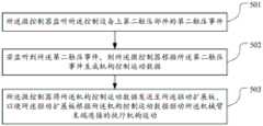
步骤501、所述微控制器监听所述控制设备上第二触发部件的第二触发事件;
对于鼠标来说,其上可以配置有至少一个按键作为控制设备的第二触发部件。本实施例中,可以对鼠标的按键的触压时间进行监听,以判断用户是否对鼠标进行了触压操作。For a mouse, at least one key may be configured thereon as a second trigger component of the control device. In this embodiment, the pressing time of the button of the mouse may be monitored to determine whether the user has performed a pressing operation on the mouse.
步骤502、若监听到所述第二触发事件,则所述微控制器根据所述第二触发事件生成机构控制运动数据;
步骤503、所述微控制器将所述机构控制运动数据发送至所述驱动扩展板,以使所述驱动扩展板根据所述机构控制运动数据驱动所述机械臂末端连接的执行机构运动。Step 503: The microcontroller sends the mechanism control motion data to the drive expansion board, so that the drive expansion board drives the actuator connected to the end of the robotic arm to move according to the mechanism control motion data.
对于上述步骤502和步骤503,当监听到第二触发事件时,所述微控制器即可生成对机械臂末端连接的执行机构进行控制的机构控制运动数据,并将该机构控制运动数据发送至图1f所示的驱动扩展板,该驱动扩展板直接根据该机构运动数据驱动该执行机构运动。在本发明实施例中,所述机械臂末端连接的执行机构,包括但不限于机械臂末端的旋转机构(例如舵机),或者还包括与该旋转机构连接的爪子、吸盘等装置,该机构的种类不同,所能够实现的功能也不相同,总体来说,该执行机构是用于实现机械臂更为精细的机械控制,例如抓握物体、绘画、激光刻字,等等。For the
以下通过若干实施例来对图5实施例的实现进行详细阐述:The implementation of the embodiment of FIG. 5 will be described in detail below through several embodiments:
作为本发明的一个实施例,步骤502可以具体通过以下方式实现:As an embodiment of the present invention, step 502 can be specifically implemented in the following manner:
若监听到关于所述第二触发部件的双击操作事件,则所述微控制器根据所述双击操作事件生成第一机构控制运动数据,所述第一机构控制运动数据用于控制所述执行机构在打开状态和关闭状态之间的切换。在本实施例中,该第二触发部件可以是鼠标左键、鼠标右键或者鼠标上配置的其他物理按键。当监听到该第二触发部件被双击时,则所述微控制器生成第一机构控制运动数据,并将该第一机构控制运动数据发送至驱动扩展板。若机械臂的执行机构正处于打开状态,则当机械臂上的驱动扩展板接收到该第一机构控制运动数据时,驱动扩展板控制机械臂的执行机构从打开状态切换至关闭状态;反之,若机械臂的执行机构正处于关闭状态,则当驱动扩展板接收到该第一机构控制运动数据时,驱动扩展板控制机械臂的执行机构从关闭状态切换至打开状态。If a double-click operation event on the second trigger component is monitored, the microcontroller generates first mechanism control motion data according to the double-click operation event, and the first mechanism control motion data is used to control the actuator Toggle between on and off state. In this embodiment, the second trigger component may be a left mouse button, a right mouse button, or other physical buttons configured on the mouse. When it is detected that the second trigger component is double-clicked, the microcontroller generates first mechanism control motion data, and sends the first mechanism control motion data to the drive expansion board. If the actuator of the manipulator is in the open state, when the drive expansion board on the manipulator receives the first mechanism control motion data, the drive expansion board controls the actuator of the manipulator to switch from the open state to the closed state; otherwise, If the actuator of the manipulator is in a closed state, when the drive expansion board receives the first mechanism control motion data, the drive expansion board controls the actuator of the manipulator to switch from the closed state to the open state.
作为本发明的又一个实施例,步骤502还可以具体通过以下方式实现:As another embodiment of the present invention, step 502 can also be specifically implemented in the following manner:
若监听到所述第二触发部件处于被按下的状态,则所述微控制器生成第二机构控制运动数据,所述第二机构控制运动数据用于打开所述执行机构;若监听到所述第二触发部件处于松开状态,则所述微控制器生成第三机构控制运动数据,所述第三机构控制运动数据用于关闭所述执行机构。在本实施例中,该第二触发部件可以是鼠标左键、鼠标右键或者鼠标上配置的其他物理按键。当监听到该第二触发部件处于被按下的状态时,则所述微控制器生成第二机构控制运动数据,并将该第二机构控制运动数据发送至机械臂上的驱动扩展板,驱动扩展板控制机械臂的执行机构打开;而当监听到该第二触发部件处于松开状态时,则微控制器生成第三机构控制运动数据,并将该第三机构控制运动数据发送至驱动扩展板,驱动扩展板控制机械臂的执行机构关闭。示例性地,在一个应用场景下,用户按下某按键时,机械臂末端的执行机构打开、启动并执行相应操作。用户保持按下该按键的状态,该执行机构持续作业,直到用户认为该执行机构已完成阶段性的作业时,用户松开该按键,该执行机构则关闭,停止作业。If it is monitored that the second trigger part is in the pressed state, the microcontroller generates second mechanism control motion data, and the second mechanism control motion data is used to open the actuator; If the second trigger part is in a released state, the microcontroller generates third mechanism control motion data, and the third mechanism control motion data is used to close the actuator. In this embodiment, the second trigger component may be a left mouse button, a right mouse button, or other physical buttons configured on the mouse. When monitoring that the second trigger component is in the pressed state, the microcontroller generates the second mechanism control motion data, and sends the second mechanism control motion data to the drive expansion board on the robotic arm, driving the The expansion board controls the actuator of the mechanical arm to open; and when monitoring that the second trigger part is in the released state, the microcontroller generates the third mechanism control motion data, and sends the third mechanism control motion data to the drive extension board, which drives the expansion board to control the closing of the actuator of the robotic arm. Exemplarily, in an application scenario, when a user presses a button, the actuator at the end of the robotic arm is turned on, started, and performs a corresponding operation. The user keeps pressing the button, the actuator continues to work, until the user thinks that the actuator has completed the phased operation, the user releases the button, the actuator is turned off, and the operation stops.
需要说明的是,上述的第一触发部件、第二触发部件具体可以是控制设备上的按键、摇杆、弹性结构、移动部件等一切可以进行指令输入的部件。控制设备可以预先设定哪一个部件为第一触发部件,哪一个部件为第二触发部件,当相应部件被触发(比如,被按下、被触压、被提起、被扭动,等等) 时,则生成对应的触发事件,比如上述的第一触发事件或第二触发事件。It should be noted that the above-mentioned first triggering component and second triggering component may specifically be all components that can perform command input, such as buttons, joysticks, elastic structures, and moving components on the control device. The control device can preset which part is the first trigger part and which part is the second trigger part, when the corresponding part is triggered (for example, pressed, pressed, lifted, twisted, etc.) is generated, a corresponding trigger event is generated, such as the above-mentioned first trigger event or second trigger event.
在本发明实施例中,微控制器通过预先建立控制设备的移动部件与机械臂之间运动坐标系的转换关系,将移动部件的移动情况转换成对机械臂进行控制的控制运动数据,从而建立起控制设备上移动部件与机械臂运动的直观联系,提升了机械臂的运动控制效率。In the embodiment of the present invention, the microcontroller converts the movement of the moving part into control motion data for controlling the mechanical arm by pre-establishing the conversion relationship between the moving part of the control device and the mechanical arm, thereby establishing The intuitive connection between the moving parts on the control device and the motion of the manipulator improves the motion control efficiency of the manipulator.
进一步地,微控制器还通过预先建立旋钮与目标旋转轴之间转动坐标系的转换关系,将旋钮的转动情况转换成对目标旋转轴的控制运动数据,从而建立起控制设备上旋钮与机械臂上目标旋转轴转动的直观联系,提升了机械臂旋转轴的运动控制效率。Further, the microcontroller also converts the rotation of the knob into the control motion data for the target rotation axis by pre-establishing the conversion relationship between the rotary coordinate system between the knob and the target rotation axis, thereby establishing the control device on the knob and the mechanical arm. The intuitive connection of the rotation of the upper target rotation axis improves the motion control efficiency of the rotation axis of the manipulator.
应理解,上述实施例中各步骤的序号的大小并不意味着执行顺序的先后,各过程的执行顺序应以其功能和内在逻辑确定,而不应对本发明实施例的实施过程构成任何限定。It should be understood that the size of the sequence numbers of the steps in the above embodiments does not mean the sequence of execution, and the execution sequence of each process should be determined by its functions and internal logic, and should not constitute any limitation to the implementation process of the embodiments of the present invention.
对应于上文实施例所述的机械臂的运动控制方法,图6示出了本发明实施例提供的机械臂的微控制器的结构框图。为了便于说明,仅示出了与本实施例相关的部分。Corresponding to the motion control method of the robotic arm described in the above embodiments, FIG. 6 shows a structural block diagram of the microcontroller of the robotic arm provided by the embodiment of the present invention. For convenience of explanation, only the parts related to this embodiment are shown.
本实施例中,一种设于机械臂上的微控制器包括:In this embodiment, a microcontroller provided on the robotic arm includes:
移动检测模块601,用于获取来自控制设备的所述控制设备上移动部件的移动方向和在所述移动方向上的移动距离,所述移动方向和所述移动距离为所述控制设备通过对所述移动部件的移动情况进行检测得到;The
运动方向转换模块602,用于将所述移动部件的移动方向转换为机械臂的运动方向;a movement
运动速度转换模块603,用于根据所述移动部件的所述移动距离确定所述机械臂在所述运动方向上的运动速度;a movement
第一运动数据生成模块604,用于生成第一运动数据,所述第一运动数据用于控制所述机械臂以所述运动速度沿所述运动方向运动;a first motion
第一运动数据发送模块605,用于将所述第一运动数据发送至所述机械臂的驱动扩展板。The first motion
进一步地,所述微控制器还可以包括:Further, the microcontroller may also include:
第一触发事件监听模块,用于监听所述控制设备上第一触发部件的第一触发事件;a first trigger event monitoring module for monitoring the first trigger event of the first trigger component on the control device;
监听触发模块,用于若所述第一触发事件监听模块监听到所述第一触发事件,则触发所述移动检测模块。and a monitoring trigger module, configured to trigger the movement detection module if the first trigger event monitoring module monitors the first trigger event.
进一步地,所述第一触发事件监听模块可以包括:Further, the first trigger event monitoring module may include:
第一状态监听单元,用于监听所述第一触发部件是否处于被按下的状态;a first state monitoring unit for monitoring whether the first trigger component is in a pressed state;
第一触发确定单元,用于若所述第一触发部件处于被按下的状态,则确定监听到所述第一触发事件;a first trigger determination unit, configured to determine that the first trigger event is monitored if the first trigger component is in a pressed state;
所述微控制器还可以包括The microcontroller may also include
状态数据生成模块,用于若监听到所述第一触发部件处于松开状态,则生成第二运动数据;a state data generating module, configured to generate second motion data if it is detected that the first trigger part is in a loosened state;
状态数据发送模块,用于将所述状态数据生成模块生成的所述第二运动数据发送至所述驱动扩展板,以使所述驱动扩展板根据所述第二运动数据控制所述机械臂停止运动。a state data sending module, configured to send the second motion data generated by the state data generating module to the drive expansion board, so that the drive expansion board controls the robotic arm to stop according to the second motion data sports.
进一步地,所述微控制器还可以包括:Further, the microcontroller may also include:
转动检测模块,用于获取来自控制设备的所述控制设备上旋钮的第一转动方向及在所述第一转动方向上的第一角度增量,所述第一转动方向和所述第一角度增量为所述控制设备通过对所述旋钮的转动情况进行检测得到;A rotation detection module for acquiring the first rotation direction of the knob on the control device from the control device and the first angle increment in the first rotation direction, the first rotation direction and the first angle The increment is obtained by the control device by detecting the rotation of the knob;
转动方向转换模块,用于将所述旋钮的第一转动方向转换为机械臂的目标旋转轴的第二转动方向;a rotation direction conversion module, configured to convert the first rotation direction of the knob to the second rotation direction of the target rotation axis of the mechanical arm;
转动角度转换模块,用于将所述旋钮的第一角度增量转换为所述目标旋转轴在所述第二转动方向上的转动角度;a rotation angle conversion module, configured to convert the first angle increment of the knob into the rotation angle of the target rotation axis in the second rotation direction;
转动数据生成模块,用于生成转动运动数据,所述转动运动数据用于控制所述目标旋转轴沿所述第二转动方向转动所述转动角度;a rotation data generation module, configured to generate rotation motion data, where the rotation motion data is used to control the target rotation axis to rotate the rotation angle along the second rotation direction;
转动数据发送模块,用于将所述转动运动数据发送至所述机械臂的驱动扩展板。The rotation data sending module is used for sending the rotation motion data to the drive expansion board of the mechanical arm.
进一步地,所述微控制器还可以包括:Further, the microcontroller may also include:
第二触压监听模块,用于监听所述控制设备上第二触发部件的第二触发事件;a second touch monitoring module for monitoring the second trigger event of the second trigger component on the control device;
机构数据生成模块,用于若监听到所述第二触发事件,则根据所述第二触发事件生成机构控制运动数据;a mechanism data generation module, configured to generate mechanism control motion data according to the second trigger event if the second trigger event is monitored;
机构数据发送模块,用于将所述机构控制运动数据发送至所述驱动扩展板,以使所述驱动扩展板根据所述机构控制运动数据驱动所述机械臂末端连接的执行机构运动。A mechanism data sending module, configured to send the mechanism control motion data to the drive expansion board, so that the drive expansion board drives the actuator connected to the end of the mechanical arm to move according to the mechanism control motion data.
进一步地,所述机构指令生成模块可以包括:Further, the mechanism instruction generation module may include:
第一机构数据生成单元,用于若监听到关于所述第二触发部件的双击操作事件,则根据所述双击操作事件生成第一机构控制运动数据,所述第一机构控制运动数据用于控制所述执行机构在打开状态和关闭状态之间的切换;The first mechanism data generation unit is used to generate first mechanism control motion data according to the double-click operation event if the double-click operation event on the second trigger component is monitored, and the first mechanism control motion data is used to control the switching of the actuator between an open state and a closed state;
和/或and / or
第二机构数据生成单元,用于若监听到所述第二触发部件处于被按下的状态,则生成第二机构控制运动数据,所述第二机构控制运动数据用于打开所述执行机构;A second mechanism data generating unit, configured to generate second mechanism control motion data if it is monitored that the second trigger member is in a pressed state, and the second mechanism control motion data is used to open the actuator;
第三机构数据生成单元,用于若监听到所述第二触发部件处于松开状态,则生成第三机构控制运动数据,所述第三机构控制运动数据用于关闭所述执行机构。The third mechanism data generating unit is configured to generate third mechanism control motion data if it is detected that the second trigger member is in a released state, and the third mechanism control motion data is used to close the actuator.
图7是本发明一实施例提供的微控制器的示意图。如图7所示,该实施例的微控制器7包括:处理器70、存储器71以及存储在所述存储器71中并可在所述处理器70上运行的计算机程序72,例如机械臂的运动控制程序。所述处理器70执行所述计算机程序72时实现上述各个机械臂的运动控制方法实施例中的步骤,例如图3所示的步骤301至305。或者,所述处理器70执行所述计算机程序72时实现上述各装置实施例中各模块/单元的功能,例如图6所示模块601至605的功能。FIG. 7 is a schematic diagram of a microcontroller according to an embodiment of the present invention. As shown in FIG. 7 , the
示例性的,所述计算机程序72可以被分割成一个或多个模块/单元,所述一个或者多个模块/单元被存储在所述存储器71中,并由所述处理器70执行,以完成本发明。所述一个或多个模块/单元可以是能够完成特定功能的一系列计算机程序指令段,该指令段用于描述所述计算机程序72在所述微控制器7 中的执行过程。Exemplarily, the
所述微控制器7可以是MCU(Microcontroller Unit),其可包括,但不仅限于,处理器70、存储器71。本领域技术人员可以理解,图7仅仅是微控制器7的示例,并不构成对微控制器7的限定,可以包括比图示更多或更少的部件,或者组合某些部件,或者不同的部件,例如所述微控制器还可以包括输入输出设备、网络接入设备、总线等。The
所述处理器70可以是中央处理单元(Central Processing Unit,CPU),还可以是其他通用处理器、数字信号处理器(Digital Signal Processor,DSP)、专用集成电路(Application Specific Integrated Circuit,ASIC)、现成可编程门阵列 (Field-Programmable Gate Array,FPGA)或者其他可编程逻辑器件、分立门或者晶体管逻辑器件、分立硬件组件等。通用处理器可以是微处理器或者该处理器也可以是任何常规的处理器等。The
所述存储器71可以是所述微控制器7的内部存储单元,例如微控制器7 的硬盘或内存。所述存储器71也可以是所述微控制器7的外部存储设备,例如所述微控制器7上配备的插接式硬盘,智能存储卡(Smart Media Card, SMC),安全数字(Secure Digital,SD)卡,闪存卡(Flash Card)等。进一步地,所述存储器71还可以既包括所述微控制器7的内部存储单元也包括外部存储设备。所述存储器71用于存储所述计算机程序以及所述计算机所需的其他程序和数据。所述存储器71还可以用于暂时地存储已经输出或者将要输出的数据。The
所属领域的技术人员可以清楚地了解到,为描述的方便和简洁,上述描述的系统,装置和单元的具体工作过程,可以参考前述方法实施例中的对应过程,在此不再赘述。Those skilled in the art can clearly understand that, for the convenience and brevity of description, the specific working process of the system, device and unit described above may refer to the corresponding process in the foregoing method embodiments, which will not be repeated here.
在本申请所提供的几个实施例中,应该理解到,所揭露的系统,装置和方法,可以通过其它的方式实现。例如,以上所描述的装置实施例仅仅是示意性的,例如,所述单元的划分,仅仅为一种逻辑功能划分,实际实现时可以有另外的划分方式,例如多个单元或组件可以结合或者可以集成到另一个系统,或一些特征可以忽略,或不执行。另一点,所显示或讨论的相互之间的耦合或直接耦合或通信连接可以是通过一些接口,装置或单元的间接耦合或通信连接,可以是电性,机械或其它的形式。In the several embodiments provided in this application, it should be understood that the disclosed system, apparatus and method may be implemented in other manners. For example, the apparatus embodiments described above are only illustrative. For example, the division of the units is only a logical function division. In actual implementation, there may be other division methods. For example, multiple units or components may be combined or Can be integrated into another system, or some features can be ignored, or not implemented. On the other hand, the shown or discussed mutual coupling or direct coupling or communication connection may be through some interfaces, indirect coupling or communication connection of devices or units, and may be in electrical, mechanical or other forms.
所述作为分离部件说明的单元可以是或者也可以不是物理上分开的,作为单元显示的部件可以是或者也可以不是物理单元,即可以位于一个地方,或者也可以分布到多个网络单元上。可以根据实际的需要选择其中的部分或者全部单元来实现本实施例方案的目的。The units described as separate components may or may not be physically separated, and components displayed as units may or may not be physical units, that is, may be located in one place, or may be distributed to multiple network units. Some or all of the units may be selected according to actual needs to achieve the purpose of the solution in this embodiment.
另外,在本发明各个实施例中的各功能单元可以集成在一个处理单元中,也可以是各个单元单独物理存在,也可以两个或两个以上单元集成在一个单元中。上述集成的单元既可以采用硬件的形式实现,也可以采用软件功能单元的形式实现。In addition, each functional unit in each embodiment of the present invention may be integrated into one processing unit, or each unit may exist physically alone, or two or more units may be integrated into one unit. The above-mentioned integrated units may be implemented in the form of hardware, or may be implemented in the form of software functional units.
所述集成的单元如果以软件功能单元的形式实现并作为独立的产品销售或使用时,可以存储在一个计算机可读取存储介质中。基于这样的理解,本发明的技术方案本质上或者说对现有技术做出贡献的部分或者该技术方案的全部或部分可以以软件产品的形式体现出来,该计算机软件产品存储在一个存储介质中,包括若干指令用以使得一台计算机设备(可以是个人计算机,服务器,或者网络设备等)执行本发明各个实施例所述方法的全部或部分步骤。而前述的存储介质包括:U盘、移动硬盘、只读存储器(ROM,Read-OnlyMemory)、随机存取存储器(RAM,Random Access Memory)、磁碟或者光盘等各种可以存储程序代码的介质。The integrated unit, if implemented in the form of a software functional unit and sold or used as an independent product, may be stored in a computer-readable storage medium. Based on this understanding, the technical solution of the present invention is essentially or the part that contributes to the prior art, or all or part of the technical solution can be embodied in the form of a software product, and the computer software product is stored in a storage medium , including several instructions for causing a computer device (which may be a personal computer, a server, or a network device, etc.) to execute all or part of the steps of the methods described in the various embodiments of the present invention. The aforementioned storage medium includes: U disk, removable hard disk, Read-Only Memory (ROM, Read-Only Memory), Random Access Memory (RAM, Random Access Memory), magnetic disk or optical disk and other media that can store program codes.
以上所述,以上实施例仅用以说明本发明的技术方案,而非对其限制;尽管参照前述实施例对本发明进行了详细的说明,本领域的普通技术人员应当理解:其依然可以对前述各实施例所记载的技术方案进行修改,或者对其中部分技术特征进行等同替换;而这些修改或者替换,并不使相应技术方案的本质脱离本发明各实施例技术方案的精神和范围。As mentioned above, the above embodiments are only used to illustrate the technical solutions of the present invention, but not to limit them; although the present invention has been described in detail with reference to the foregoing embodiments, those of ordinary skill in the art should understand: The technical solutions described in the embodiments are modified, or some technical features thereof are equivalently replaced; and these modifications or replacements do not make the essence of the corresponding technical solutions depart from the spirit and scope of the technical solutions of the embodiments of the present invention.
Claims (10)
Translated fromChinesePriority Applications (1)
| Application Number | Priority Date | Filing Date | Title |
|---|---|---|---|
| CN201710379367.2ACN107214699B (en) | 2017-05-25 | 2017-05-25 | Motion control method of mechanical arm, microcontroller and storage medium |
Applications Claiming Priority (1)
| Application Number | Priority Date | Filing Date | Title |
|---|---|---|---|
| CN201710379367.2ACN107214699B (en) | 2017-05-25 | 2017-05-25 | Motion control method of mechanical arm, microcontroller and storage medium |
Publications (2)
| Publication Number | Publication Date |
|---|---|
| CN107214699A CN107214699A (en) | 2017-09-29 |
| CN107214699Btrue CN107214699B (en) | 2020-07-31 |
Family
ID=59945173
Family Applications (1)
| Application Number | Title | Priority Date | Filing Date |
|---|---|---|---|
| CN201710379367.2AActiveCN107214699B (en) | 2017-05-25 | 2017-05-25 | Motion control method of mechanical arm, microcontroller and storage medium |
Country Status (1)
| Country | Link |
|---|---|
| CN (1) | CN107214699B (en) |
Families Citing this family (1)
| Publication number | Priority date | Publication date | Assignee | Title |
|---|---|---|---|---|
| CN108527405A (en)* | 2018-03-30 | 2018-09-14 | 天津大学 | A kind of cooperation robot guiding teaching system |
Citations (6)
| Publication number | Priority date | Publication date | Assignee | Title |
|---|---|---|---|---|
| CN101870107A (en)* | 2010-06-26 | 2010-10-27 | 上海交通大学 | Control system of orthopedic surgery assistant robot |
| CN102310407A (en)* | 2011-04-22 | 2012-01-11 | 三一重工股份有限公司 | Bionic control method and control system of mechanical arm |
| CN104159016A (en)* | 2013-05-13 | 2014-11-19 | 浙江大华技术股份有限公司 | Cradle head control system, method and device |
| CN106064378A (en)* | 2016-06-07 | 2016-11-02 | 南方科技大学 | Control method and device for unmanned aerial vehicle mechanical arm |
| CN106182020A (en)* | 2016-07-13 | 2016-12-07 | 上海航天控制技术研究所 | A kind of robot manipulation's teaching system based on synchronous robot and method |
| CN106182003A (en)* | 2016-08-01 | 2016-12-07 | 清华大学 | A kind of mechanical arm teaching method, Apparatus and system |
- 2017
- 2017-05-25CNCN201710379367.2Apatent/CN107214699B/enactiveActive
Patent Citations (6)
| Publication number | Priority date | Publication date | Assignee | Title |
|---|---|---|---|---|
| CN101870107A (en)* | 2010-06-26 | 2010-10-27 | 上海交通大学 | Control system of orthopedic surgery assistant robot |
| CN102310407A (en)* | 2011-04-22 | 2012-01-11 | 三一重工股份有限公司 | Bionic control method and control system of mechanical arm |
| CN104159016A (en)* | 2013-05-13 | 2014-11-19 | 浙江大华技术股份有限公司 | Cradle head control system, method and device |
| CN106064378A (en)* | 2016-06-07 | 2016-11-02 | 南方科技大学 | Control method and device for unmanned aerial vehicle mechanical arm |
| CN106182020A (en)* | 2016-07-13 | 2016-12-07 | 上海航天控制技术研究所 | A kind of robot manipulation's teaching system based on synchronous robot and method |
| CN106182003A (en)* | 2016-08-01 | 2016-12-07 | 清华大学 | A kind of mechanical arm teaching method, Apparatus and system |
Also Published As
| Publication number | Publication date |
|---|---|
| CN107214699A (en) | 2017-09-29 |
Similar Documents
| Publication | Publication Date | Title |
|---|---|---|
| CN107186715B (en) | Method and device for controlling movement of mechanical arm, storage medium and computer | |
| US11007651B2 (en) | Haptic controller with touch-sensitive control knob | |
| JP6497021B2 (en) | Robot operation device, robot system, and robot operation program | |
| US9857962B2 (en) | Robot operation apparatus and robot operation program product | |
| JP6476662B2 (en) | Robot operation device, robot system, and robot operation program | |
| CN107260314A (en) | Surgical robot and device and system in surgical robot | |
| CN107363835B (en) | Configuration method, device, medium and robot system of motion control components | |
| JP2017071018A (en) | Robot system, robot, and robot controller | |
| CN113183150B (en) | Bionic hand control optimization method and system and electronic equipment | |
| JP2021100788A (en) | Robot operation device, and robot operation program | |
| CN107160391B (en) | Motion control method of mechanical arm, third-party processing terminal and storage medium | |
| CN114714358A (en) | Method and system for teleoperation of mechanical arm based on gesture protocol | |
| CN107562017A (en) | Parameter edit methods, computer-readable medium and the computer of control parts of motion | |
| JP2018051647A (en) | Robot control device, robot and robot system | |
| CN107214699B (en) | Motion control method of mechanical arm, microcontroller and storage medium | |
| CN107199564B (en) | Method and device for controlling movement of mechanical arm, storage medium and computer | |
| CN107263471B (en) | Motion control method of robotic arm, third-party processing terminal and storage medium | |
| JP6379902B2 (en) | Robot operation device, robot system, and robot operation program | |
| CN107160393A (en) | Motion control method and device and storage medium, the computer of mechanical arm | |
| CN107291049B (en) | Motion control method and device for robotic arm | |
| TWI767265B (en) | Method for controlling working endpoint of multi-axis object in two-dimensional display interface | |
| JP2017052031A (en) | Robot operation device and robot operation method | |
| JP6379921B2 (en) | Robot operation device, robot system, and robot operation program | |
| CN205497463U (en) | Disconnect -type robot drags teaching handle | |
| CN107081758A (en) | Motion control method, microcontroller and the storage medium of mechanical arm |
Legal Events
| Date | Code | Title | Description |
|---|---|---|---|
| PB01 | Publication | ||
| PB01 | Publication | ||
| SE01 | Entry into force of request for substantive examination | ||
| SE01 | Entry into force of request for substantive examination | ||
| GR01 | Patent grant | ||
| GR01 | Patent grant | ||
| CP03 | Change of name, title or address | Address after:518000 18 / F, building C2, Nanshan wisdom Park, 1001 Xueyuan Avenue, Xili University Town, Taoyuan Street, Nanshan District, Shenzhen City, Guangdong Province Patentee after:Shenzhen Yuejiang Technology Co.,Ltd. Country or region after:China Address before:518000 18 / F, building C2, Nanshan wisdom Park, 1001 Xueyuan Avenue, Xili University Town, Taoyuan Street, Nanshan District, Shenzhen City, Guangdong Province Patentee before:SHENZHEN YUEJIANG TECHNOLOGY Co.,Ltd. Country or region before:China | |
| CP03 | Change of name, title or address |