CN107206597B - Robots and Robotic Systems - Google Patents
Robots and Robotic SystemsDownload PDFInfo
- Publication number
- CN107206597B CN107206597BCN201680008794.3ACN201680008794ACN107206597BCN 107206597 BCN107206597 BCN 107206597BCN 201680008794 ACN201680008794 ACN 201680008794ACN 107206597 BCN107206597 BCN 107206597B
- Authority
- CN
- China
- Prior art keywords
- link member
- arc
- shaped portion
- manipulator
- predetermined
- Prior art date
- Legal status (The legal status is an assumption and is not a legal conclusion. Google has not performed a legal analysis and makes no representation as to the accuracy of the status listed.)
- Active
Links
Images


Classifications
- A—HUMAN NECESSITIES
- A61—MEDICAL OR VETERINARY SCIENCE; HYGIENE
- A61B—DIAGNOSIS; SURGERY; IDENTIFICATION
- A61B1/00—Instruments for performing medical examinations of the interior of cavities or tubes of the body by visual or photographical inspection, e.g. endoscopes; Illuminating arrangements therefor
- A61B1/005—Flexible endoscopes
- A61B1/0051—Flexible endoscopes with controlled bending of insertion part
- A61B1/0057—Constructional details of force transmission elements, e.g. control wires
- A—HUMAN NECESSITIES
- A61—MEDICAL OR VETERINARY SCIENCE; HYGIENE
- A61B—DIAGNOSIS; SURGERY; IDENTIFICATION
- A61B1/00—Instruments for performing medical examinations of the interior of cavities or tubes of the body by visual or photographical inspection, e.g. endoscopes; Illuminating arrangements therefor
- A61B1/00002—Operational features of endoscopes
- A61B1/00004—Operational features of endoscopes characterised by electronic signal processing
- A61B1/00009—Operational features of endoscopes characterised by electronic signal processing of image signals during a use of endoscope
- A—HUMAN NECESSITIES
- A61—MEDICAL OR VETERINARY SCIENCE; HYGIENE
- A61B—DIAGNOSIS; SURGERY; IDENTIFICATION
- A61B1/00—Instruments for performing medical examinations of the interior of cavities or tubes of the body by visual or photographical inspection, e.g. endoscopes; Illuminating arrangements therefor
- A61B1/00131—Accessories for endoscopes
- A61B1/00133—Drive units for endoscopic tools inserted through or with the endoscope
- A—HUMAN NECESSITIES
- A61—MEDICAL OR VETERINARY SCIENCE; HYGIENE
- A61B—DIAGNOSIS; SURGERY; IDENTIFICATION
- A61B1/00—Instruments for performing medical examinations of the interior of cavities or tubes of the body by visual or photographical inspection, e.g. endoscopes; Illuminating arrangements therefor
- A61B1/005—Flexible endoscopes
- A61B1/0051—Flexible endoscopes with controlled bending of insertion part
- A61B1/0055—Constructional details of insertion parts, e.g. vertebral elements
- A—HUMAN NECESSITIES
- A61—MEDICAL OR VETERINARY SCIENCE; HYGIENE
- A61B—DIAGNOSIS; SURGERY; IDENTIFICATION
- A61B17/00—Surgical instruments, devices or methods
- A61B17/00234—Surgical instruments, devices or methods for minimally invasive surgery
- A—HUMAN NECESSITIES
- A61—MEDICAL OR VETERINARY SCIENCE; HYGIENE
- A61B—DIAGNOSIS; SURGERY; IDENTIFICATION
- A61B34/00—Computer-aided surgery; Manipulators or robots specially adapted for use in surgery
- A61B34/70—Manipulators specially adapted for use in surgery
- A61B34/71—Manipulators operated by drive cable mechanisms
- A—HUMAN NECESSITIES
- A61—MEDICAL OR VETERINARY SCIENCE; HYGIENE
- A61B—DIAGNOSIS; SURGERY; IDENTIFICATION
- A61B90/00—Instruments, implements or accessories specially adapted for surgery or diagnosis and not covered by any of the groups A61B1/00 - A61B50/00, e.g. for luxation treatment or for protecting wound edges
- A61B90/06—Measuring instruments not otherwise provided for
- B—PERFORMING OPERATIONS; TRANSPORTING
- B25—HAND TOOLS; PORTABLE POWER-DRIVEN TOOLS; MANIPULATORS
- B25J—MANIPULATORS; CHAMBERS PROVIDED WITH MANIPULATION DEVICES
- B25J13/00—Controls for manipulators
- B25J13/04—Foot-operated control means
- B—PERFORMING OPERATIONS; TRANSPORTING
- B25—HAND TOOLS; PORTABLE POWER-DRIVEN TOOLS; MANIPULATORS
- B25J—MANIPULATORS; CHAMBERS PROVIDED WITH MANIPULATION DEVICES
- B25J17/00—Joints
- B—PERFORMING OPERATIONS; TRANSPORTING
- B25—HAND TOOLS; PORTABLE POWER-DRIVEN TOOLS; MANIPULATORS
- B25J—MANIPULATORS; CHAMBERS PROVIDED WITH MANIPULATION DEVICES
- B25J18/00—Arms
- B25J18/06—Arms flexible
- A—HUMAN NECESSITIES
- A61—MEDICAL OR VETERINARY SCIENCE; HYGIENE
- A61B—DIAGNOSIS; SURGERY; IDENTIFICATION
- A61B1/00—Instruments for performing medical examinations of the interior of cavities or tubes of the body by visual or photographical inspection, e.g. endoscopes; Illuminating arrangements therefor
- A61B1/00064—Constructional details of the endoscope body
- A61B1/00071—Insertion part of the endoscope body
- A61B1/0008—Insertion part of the endoscope body characterised by distal tip features
- A61B1/00087—Tools
- A—HUMAN NECESSITIES
- A61—MEDICAL OR VETERINARY SCIENCE; HYGIENE
- A61B—DIAGNOSIS; SURGERY; IDENTIFICATION
- A61B1/00—Instruments for performing medical examinations of the interior of cavities or tubes of the body by visual or photographical inspection, e.g. endoscopes; Illuminating arrangements therefor
- A61B1/005—Flexible endoscopes
- A61B1/008—Articulations
- A—HUMAN NECESSITIES
- A61—MEDICAL OR VETERINARY SCIENCE; HYGIENE
- A61B—DIAGNOSIS; SURGERY; IDENTIFICATION
- A61B17/00—Surgical instruments, devices or methods
- A61B17/28—Surgical forceps
- A—HUMAN NECESSITIES
- A61—MEDICAL OR VETERINARY SCIENCE; HYGIENE
- A61B—DIAGNOSIS; SURGERY; IDENTIFICATION
- A61B17/00—Surgical instruments, devices or methods
- A61B17/00234—Surgical instruments, devices or methods for minimally invasive surgery
- A61B2017/00292—Surgical instruments, devices or methods for minimally invasive surgery mounted on or guided by flexible, e.g. catheter-like, means
- A61B2017/003—Steerable
- A61B2017/00305—Constructional details of the flexible means
- A61B2017/00314—Separate linked members
- A—HUMAN NECESSITIES
- A61—MEDICAL OR VETERINARY SCIENCE; HYGIENE
- A61B—DIAGNOSIS; SURGERY; IDENTIFICATION
- A61B17/00—Surgical instruments, devices or methods
- A61B17/00234—Surgical instruments, devices or methods for minimally invasive surgery
- A61B2017/00292—Surgical instruments, devices or methods for minimally invasive surgery mounted on or guided by flexible, e.g. catheter-like, means
- A61B2017/003—Steerable
- A61B2017/00318—Steering mechanisms
- A61B2017/00323—Cables or rods
- A—HUMAN NECESSITIES
- A61—MEDICAL OR VETERINARY SCIENCE; HYGIENE
- A61B—DIAGNOSIS; SURGERY; IDENTIFICATION
- A61B34/00—Computer-aided surgery; Manipulators or robots specially adapted for use in surgery
- A61B34/30—Surgical robots
- A61B2034/305—Details of wrist mechanisms at distal ends of robotic arms
- A—HUMAN NECESSITIES
- A61—MEDICAL OR VETERINARY SCIENCE; HYGIENE
- A61B—DIAGNOSIS; SURGERY; IDENTIFICATION
- A61B34/00—Computer-aided surgery; Manipulators or robots specially adapted for use in surgery
- A61B34/70—Manipulators specially adapted for use in surgery
- A61B34/71—Manipulators operated by drive cable mechanisms
- A61B2034/715—Cable tensioning mechanisms for removing slack
- A—HUMAN NECESSITIES
- A61—MEDICAL OR VETERINARY SCIENCE; HYGIENE
- A61B—DIAGNOSIS; SURGERY; IDENTIFICATION
- A61B90/00—Instruments, implements or accessories specially adapted for surgery or diagnosis and not covered by any of the groups A61B1/00 - A61B50/00, e.g. for luxation treatment or for protecting wound edges
- A61B90/06—Measuring instruments not otherwise provided for
- A61B2090/064—Measuring instruments not otherwise provided for for measuring force, pressure or mechanical tension
Landscapes
- Health & Medical Sciences (AREA)
- Life Sciences & Earth Sciences (AREA)
- Engineering & Computer Science (AREA)
- Surgery (AREA)
- Public Health (AREA)
- Molecular Biology (AREA)
- Veterinary Medicine (AREA)
- Nuclear Medicine, Radiotherapy & Molecular Imaging (AREA)
- General Health & Medical Sciences (AREA)
- Animal Behavior & Ethology (AREA)
- Biomedical Technology (AREA)
- Heart & Thoracic Surgery (AREA)
- Medical Informatics (AREA)
- Pathology (AREA)
- Robotics (AREA)
- Radiology & Medical Imaging (AREA)
- Physics & Mathematics (AREA)
- Optics & Photonics (AREA)
- Biophysics (AREA)
- Mechanical Engineering (AREA)
- Oral & Maxillofacial Surgery (AREA)
- Signal Processing (AREA)
- Manipulator (AREA)
- Instruments For Viewing The Inside Of Hollow Bodies (AREA)
- Endoscopes (AREA)
Abstract
Description
Translated fromChinese技术领域technical field
本发明涉及如下的机械手和机械手系统:能够通过使关节弯折而弯曲,进行各种处置等。The present invention relates to a manipulator and a manipulator system capable of performing various treatments and the like by bending and bending a joint.
背景技术Background technique
例如,广泛使用如下的机械手:将处置器具插入到患者的体腔内,利用线等对处置器具前端进行牵拉而使其弯曲,对体腔内的脏器进行观察,或者进行治疗。在手术时,多数情况下将用于观察的内窥镜、把持组织的钳子或切除组织的电手术刀等多个处置器具插入到体腔内。For example, a manipulator is widely used for inserting a treatment tool into a body cavity of a patient, pulling and bending the distal end of the treatment tool with a wire or the like, and observing or treating an organ in the body cavity. During surgery, a plurality of treatment instruments such as an endoscope for observation, forceps for holding tissue, and an electric scalpel for excising tissue are often inserted into a body cavity.
以往,在这样的机械手中,公开了如下构造:将引导线配置成在基底部件之间交叉并将引导线的端部固定,由此引导线一边约束基底部件间的关节的动作,一边使基底部件滚动接触地进行动作(专利文献1)。在这样的构造中,对于关节弯折时的基底部件打滑这样的动作,由引导线来承受该负荷,因此基底部件不会打滑。Conventionally, in such a manipulator, a structure has been disclosed in which a guide wire is arranged so as to intersect between base members and ends of the guide wire are fixed, whereby the guide wire restrains the movement of the joint between the base members and causes the base member to move. The components operate in rolling contact (Patent Document 1). In such a configuration, the guide wire bears the load of the base member slipping when the joint is bent, so that the base member does not slip.
现有技术文献prior art literature
专利文献Patent Literature
专利文献1:美国专利第5784542号说明书Patent Document 1: Specification of US Patent No. 5,784,542
发明内容SUMMARY OF THE INVENTION
发明要解决的课题The problem to be solved by the invention
但是,在专利文献1所记载的机械手的构造中,在至少由3个基底部件构成两个关节的情况下,需要分别将在基底部件之间交叉的引导线的端部固定。因此,必须将4条引导线固定在8个部位上,由于部件件数变多,构造复杂化,所以在组装上花费时间。However, in the structure of the manipulator described in
本发明是鉴于上述课题而完成的,提供如下的机械手和机械手系统:能够使部件件数变少,以简单的构造容易地进行组装,能够顺利地进行动作。The present invention has been made in view of the above-mentioned problems, and provides a robot and a robot system capable of reducing the number of parts, being easily assembled with a simple structure, and being able to operate smoothly.
用于解决课题的手段means of solving problems
本发明的一个实施方式的机械手的特征在于,该机械手具有:A manipulator according to an embodiment of the present invention is characterized in that the manipulator has:
操作部;以及Operations; and
弯曲部,其通过所述操作部的操作而弯曲,a bending portion, which is bent by operation of the operating portion,
所述弯曲部具有:The curved portion has:
第1连杆部件,其具有第1圆弧状部;a first link member, which has a first arc-shaped portion;
第2连杆部件,其具有第2圆弧状部;a second link member, which has a second arc-shaped portion;
中间连杆部件,其安装在所述第1连杆部件与所述第2连杆部件之间;an intermediate link member installed between the first link member and the second link member;
第1连结部件,其将所述第1连杆部件和所述中间连杆部件连结;a first connecting member connecting the first link member and the intermediate link member;
第2连结部件,其将所述第2连杆部件和所述中间连杆部件连结;以及a second connecting member connecting the second link member and the intermediate link member; and
规定部件,其被规定成在从所述第1连杆部件的所述第1圆弧状部到所述中间连杆部件的所述第1中间圆弧状部之间交叉卷绕,在从所述第2连杆部件的所述第2圆弧状部到所述中间连杆部件的所述第2中间圆弧状部之间交叉卷绕,使所述第1圆弧状部和所述第1中间圆弧状部以及所述第2圆弧状部和所述第2中间圆弧状部滚动旋转。a predetermined member which is defined so as to be cross-wound from the first arc-shaped portion of the first link member to the first intermediate arc-shaped portion of the intermediate link member, The second arc-shaped portion of the second link member is cross-wound to the second intermediate arc-shaped portion of the intermediate link member, so that the first arc-shaped portion and the The first intermediate arc-shaped portion, the second arc-shaped portion, and the second intermediate arc-shaped portion roll and rotate.
在本发明的一个实施方式的机械手中,所述规定部件是在所述第1连杆部件的所述第1圆弧状部与所述中间连杆部件的所述第1中间圆弧状部之间交叉并且在所述第2连杆部件的所述第2圆弧状部与所述中间连杆部件的所述第2中间圆弧状部之间交叉的线状部件。In the manipulator according to an embodiment of the present invention, the predetermined member is formed between the first arc-shaped portion of the first link member and the first intermediate arc-shaped portion of the intermediate link member. A linear member intersecting therebetween and intersecting between the second arc-shaped portion of the second link member and the second intermediate arc-shaped portion of the intermediate link member.
在本发明的一个实施方式的机械手中,In the manipulator of one embodiment of the present invention,
所述线状部件紧固在所述中间连杆部件上。The linear member is fastened to the intermediate link member.
在本发明的一个实施方式的机械手中,In the manipulator of one embodiment of the present invention,
所述线状部件紧固在所述第1连杆部件上。The linear member is fastened to the first link member.
在本发明的一个实施方式的机械手中,In the manipulator of one embodiment of the present invention,
所述线状部件紧固在所述第2连杆部件上。The linear member is fastened to the second link member.
在本发明的一个实施方式的机械手中,In the manipulator of one embodiment of the present invention,
所述线状部件的两端紧固在所述中间连杆部件上。Both ends of the linear member are fastened to the intermediate link member.
在本发明的一个实施方式的机械手中,In the manipulator of one embodiment of the present invention,
所述线状部件具有第1线状部件和第2线状部件,The linear member has a first linear member and a second linear member,
所述第1线状部件的一端紧固在所述第1连杆部件上,从所述第1圆弧状部卷绕在所述中间连杆部件的所述第1中间圆弧状部上,从所述第1中间圆弧状部卷绕在所述第2中间圆弧状部上,从所述第2中间圆弧状部卷绕在所述第2连杆部件的所述第2圆弧状部上,所述第1线状部件的另一端紧固在所述第2连杆部件上,One end of the first linear member is fastened to the first link member, and is wound from the first arc-shaped portion around the first intermediate arc-shaped portion of the intermediate link member is wound around the second intermediate arc-shaped portion from the first intermediate arc-shaped portion, and is wound around the second link member from the second intermediate arc-shaped portion On the arc-shaped portion, the other end of the first linear member is fastened to the second link member,
所述第2线状部件的一端紧固在所述第1连杆部件上,从所述第1圆弧状部卷绕在所述中间连杆部件的所述第1中间圆弧状部上,从所述第1中间圆弧状部卷绕在所述第2中间圆弧状部上,从所述第2中间圆弧状部卷绕在所述第2连杆部件的所述第2圆弧状部上,所述第1线状部件的另一端紧固在所述第2连杆部件上,One end of the second linear member is fastened to the first link member, and is wound from the first arc-shaped portion around the first intermediate arc-shaped portion of the intermediate link member is wound around the second intermediate arc-shaped portion from the first intermediate arc-shaped portion, and is wound around the second link member from the second intermediate arc-shaped portion On the arc-shaped portion, the other end of the first linear member is fastened to the second link member,
所述第1线状部件和所述第2线状部件在所述第1连杆部件的所述第1圆弧状部与所述中间连杆部件的所述第1中间圆弧状部之间交叉,在所述第2连杆部件的所述第2圆弧状部与所述中间连杆部件的所述第2中间圆弧状部之间交叉。The first linear member and the second linear member are located between the first arc-shaped portion of the first link member and the first intermediate arc-shaped portion of the intermediate link member. It intersects with each other between the second arc-shaped portion of the second link member and the second intermediate arc-shaped portion of the intermediate link member.
在本发明的一个实施方式的机械手中,In the manipulator of one embodiment of the present invention,
所述线状部件配设在形成于所述中间连杆部件的槽中。The linear member is arranged in a groove formed in the intermediate link member.
在本发明的一个实施方式的机械手中,In the manipulator of one embodiment of the present invention,
所述中间连杆部件具有对所述线状部件的张力进行调整的张力调整部。The intermediate link member has a tension adjusting portion that adjusts the tension of the linear member.
本发明的一个实施方式的机械手系统的特征在于,该机械手系统具有:A manipulator system according to an embodiment of the present invention is characterized in that the manipulator system has:
权利要求1至9所述的机械手,其在所述弯曲部中具有处置器具和内窥镜;The manipulator of
图像处理部,其对从所述内窥镜获得的图像信号进行图像处理;以及an image processing section that performs image processing on image signals obtained from the endoscope; and
显示部,其显示从所述图像处理部发送的影像信号。A display unit that displays the video signal sent from the image processing unit.
发明效果Invention effect
根据该方式的机械手和机械手系统,能够使部件件数变少,以简单的构造容易地进行组装,能够顺利地进行动作。According to the manipulator and the manipulator system of this aspect, the number of parts can be reduced, the assembly can be easily performed with a simple structure, and the operation can be performed smoothly.
附图说明Description of drawings
图1示出本实施方式的机械手。FIG. 1 shows the manipulator of this embodiment.
图2示出本实施方式的机械手的弯曲部的一部分。FIG. 2 shows a part of the bending portion of the manipulator of the present embodiment.
图3示出第1实施方式的机械手的弯曲部的一部分。FIG. 3 shows a part of the bending portion of the manipulator according to the first embodiment.
图4示出第1实施方式的机械手的弯曲部的动作例。FIG. 4 shows an example of the operation of the bending portion of the manipulator according to the first embodiment.
图5示出第1实施方式的规定部件的卷绕方法的其他例。FIG. 5 shows another example of the method of winding the predetermined member according to the first embodiment.
图6示出第2实施方式的机械手的弯曲部的一部分的一例。FIG. 6 shows an example of a part of the bending portion of the manipulator according to the second embodiment.
图7示出第2实施方式的规定部件的卷绕方法的其他例。FIG. 7 shows another example of the method of winding the predetermined member according to the second embodiment.
图8示出第3实施方式的机械手的弯曲部的一部分。FIG. 8 shows a part of the bending portion of the manipulator according to the third embodiment.
图9示出第4实施方式的机械手的弯曲部的一部分。FIG. 9 shows a part of the bending portion of the manipulator according to the fourth embodiment.
图10示出第5实施方式的机械手的弯曲部的一部分。FIG. 10 shows a part of the bending portion of the manipulator according to the fifth embodiment.
图11示出第6实施方式的机械手的弯曲部的一部分。FIG. 11 shows a part of the bending portion of the manipulator according to the sixth embodiment.
图12示出第6实施方式的变形例的机械手1的弯曲部4的一部分。FIG. 12 shows a part of the bending
图13示出与规定部件的安装有关的构造的一例。FIG. 13 shows an example of a structure related to the attachment of predetermined components.
图14示出与规定部件的张力调整有关的构造的一例。FIG. 14 shows an example of the structure related to the tension adjustment of the predetermined member.
图15示出应用了本实施方式的机械手的机械手系统。FIG. 15 shows a manipulator system to which the manipulator of the present embodiment is applied.
图16示出本实施方式的机械手的前端部的一例。FIG. 16 shows an example of the distal end portion of the manipulator of the present embodiment.
图17示出应用了本实施方式的机械手的机械手系统的系统结构图。FIG. 17 shows a system configuration diagram of a manipulator system to which the manipulator of the present embodiment is applied.
具体实施方式Detailed ways
以下,对实施方式进行说明。Hereinafter, the embodiment will be described.
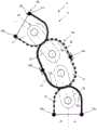
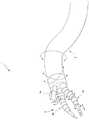
图1示出本实施方式的机械手1。FIG. 1 shows the
本实施方式的机械手1具有:主体部2;长条部3,其从主体部2延伸;弯曲部4,其与长条部3连接;以及线等动力传递部5,其传递使弯曲部4进行动作的动力。The
主体部2具有:由马达和齿轮等构成的驱动部2a,其产生传递给动力传递部5的动力;以及驱动操作部2b,其对驱动部2a进行操作。主体部2是对驱动部2a进行收纳的盒状的部分。在第1实施方式中,对动力传递部5进行收纳的长条部3从主体部2延伸。在长条部3的前端安装有能够相对于长条部3屈曲或弯曲的弯曲部4。动力传递部5具有由线等构成的第1动力传递部件5a和第2动力传递部件5b,它们的一端侧均安装在弯曲部4上,贯穿插入在长条部3的内部,另一端侧均安装在驱动部2a上。The
关于这样的构造的机械手1,在通常时通过对驱动操作部2b进行操作而使弯曲部4弯曲。当对驱动操作部2b进行操作时,驱动部2a进行驱动。驱动部2a所产生的动力对第1动力传递部件5a或第2动力传递部件5b进行牵拉。被牵拉的动力传递部5在长条部3内移动,对弯曲部4的一方进行牵拉。并且,使弯曲部4弯曲。In the
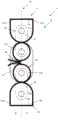
图2示出第1实施方式的机械手1的弯曲部4的一部分。FIG. 2 shows a part of the bending
本实施方式的机械手1的弯曲部4具有至少1个关节部10。关节部10具有:第1连杆部件11;第2连杆部件12;中间连杆部件13,其安装在第1连杆部件11与第2连杆部件12之间;第1连结部件21,其将第1连杆部件11和中间连杆部件13连结;第2连结部件22,其将第2连杆部件12和中间连杆部件13连结;以及规定部件30,其由卷绕在第1连杆部件11、第2连杆部件12和中间连杆部件13上的线状部件等构成。另外,弯曲部4也可以由多个关节部10形成。The bending
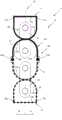
图3示出第1实施方式的机械手1的弯曲部4的一部分。FIG. 3 shows a part of the bending
在第1实施方式的机械手1的弯曲部4中,相对于1个关节部10,2根规定部件30通过6个部位的紧固部50而紧固在第1连杆部件11、第2连杆部件12和中间连杆部件13上。In the bending
第1连杆部件11具有第1圆弧状部11a、第1端面11b、一侧第1角部11c、以及另一侧第1角部11d。第2连杆部件12具有第2圆弧状部12a、第2端面12b、一侧第2角部12c、以及另一侧第2角部12d。并且,中间连杆部件13具有与第1圆弧状部11a接触的第1中间圆弧状部13a、与第2圆弧状部12a接触的第2中间圆弧状部13b、一侧中间面13c、以及另一侧中间面13d。The
连结部件20具有:第1连结部件21,其将第1连杆部件11和中间连杆部件13连结;以及第2连结部件22,其将第2连杆部件12和中间连杆部件13连结。另外,相对于将连结部件20的各旋转中心连接的线C,将一侧设为A,将另一侧设为B。The connecting
紧固部50具有:第1连杆一侧紧固部51a,其形成在第1连杆部件11的一侧A;第1连杆另一侧紧固部51b,其形成在第1连杆部件11的另一侧B;第2连杆一侧紧固部52a,其形成在第2连杆部件11的一侧A;第2连杆另一侧紧固部52b,其形成在第2连杆部件11的另一侧B;中间连杆一侧紧固部53a,其形成在中间连杆部件13的一侧A;以及中间连杆另一侧紧固部53b,其形成在中间连杆部件13的另一侧B。紧固部50通过铆接或钎焊等而构成。The
例如,第1连杆部11的紧固部50的第1连杆一侧紧固部51a形成在一侧第1角部11c,第1连杆另一侧紧固部51b形成在另一侧第1角部11d。同样地,第2连杆部12的紧固部50的第2连杆一侧紧固部52a形成在一侧第2角部12c,第2连杆另一侧紧固部52b形成在另一侧第2角部12d。并且,中间连杆部13的紧固部50的中间连杆一侧紧固部53a形成在一侧中间面13c上,中间连杆另一侧紧固部53b形成在另一侧中间面13d上。For example, the
在图3所示的例子中,使用2根规定部件30。即,规定部件30具有由线状部件等构成的第1规定部件31和第2规定部件32。In the example shown in FIG. 3 , two
第1规定部件31的一端紧固在第1连杆部件11的一侧A的第1连杆一侧紧固部51a上,卷绕在第1圆弧状部11a的至少一侧A的一部分上。接着,第1规定部件31卷绕在中间连杆部件13的第1中间圆弧状部13a的至少另一侧B的一部分上,卷绕在第2中间圆弧状部13b的至少另一侧B的一部分上。接着,第1规定部件31卷绕在第2连杆部件12的第2圆弧状部12a的至少一侧A的一部分上,紧固在一侧A的第2连杆一侧紧固部52a上。并且,第1规定部件31紧固在中间连杆另一侧紧固部53b上,该中间连杆另一侧紧固部53b形成在中间连杆部件13的另一侧B。One end of the first
第2规定部件32的一端紧固在第1连杆部件11的另一侧B的第1连杆另一侧紧固部51b上,卷绕在第1圆弧状部11a的至少另一侧B的一部分上。接着,第2规定部件32卷绕在中间连杆部件13的第1中间圆弧状部13a的至少一侧A的一部分上,卷绕在第2中间圆弧状部13b的至少一侧A的一部分上。接着,第2规定部件32卷绕在第2连杆部件12的第2圆弧状部12a的至少另一侧B的一部分上,紧固在另一侧B的第2连杆另一侧紧固部52b上。并且,第2规定部件32紧固在中间连杆一侧紧固部53a上,该中间连杆一侧紧固部53a形成在中间连杆部件13的一侧A的面上。One end of the second
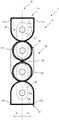
图4示出第1实施方式的机械手1的弯曲部4的动作例。FIG. 4 shows an example of the operation of the bending
图4示出将来自图1所示的驱动部2a的动力传递给动力传递部5而使弯曲部4的前端侧向另一侧B弯曲的状态。第1规定部件31和第2规定部件32分别被配置为在第1连杆部件11、第2连杆部件12和中间连杆部件13之间交叉,紧固在各紧固部50上。因此,成为如下构造:第1规定部件31和第2规定部件3至少对第1连杆部件11、第2连杆部件12和中间连杆部件13之间的关节的动作进行约束,并且使它们不会打滑地滚动旋转而进行动作。FIG. 4 shows a state in which the front end side of the bending
这样,根据第1实施方式的机械手1的弯曲部4,能够使部件件数变少,以简单的构造容易地进行组装。In this way, according to the bending
另外,在图4所示的例子中,使用了2根规定部件30,但也可以由1根~4根构成。In addition, in the example shown in FIG. 4, although two
图5示出第1实施方式的规定部件30的卷绕方法的其他例。FIG. 5 shows another example of the method of winding the
图5的(a)示出规定部件30为1根的情况,图5的(b)示出规定部件30为3根的情况,图5的(c)示出规定部件30为4根的情况。FIG. 5( a ) shows a case where there is one
在图5的(a)所示的例子中,只要对规定部件30进行卷绕,并将规定部件30的一端和另一端紧固在6个紧固部50中的任意紧固部上即可。在图5的(b)所示的例子中,将图3所示的第2规定部件32分割成将第1连杆部件11和中间连杆部件13连接的部分32a和将第2连杆部件12和中间连杆部件13连接的部分32b这两个部分,由3根规定部件30形成规定部件30。在图5的(c)所示的例子中,将图5的(b)所示的例子的第1规定部件31分割成将第1连杆部件11和中间连杆部件13连接的部分31a和将第2连杆部件12和中间连杆部件13连接的部分32b这两个部分,由4根规定部件30形成规定部件30。In the example shown in FIG. 5( a ), the
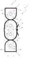
图6示出第2实施方式的机械手1的弯曲部4的一部分的一例。FIG. 6 shows an example of a part of the bending
在第2实施方式的弯曲部4中,考虑了规定部件30为1根~4根的情况。这里,对规定部件30为2根的情况进行说明。In the bending
在第2实施方式的情况下,考虑了如下的图6的(a)所示的第1紧固形式和图6的(b)所示的第2紧固形式,在图6的(a)所示的第1紧固形式中,第1规定部件31的一端和第2规定部件32的一端都通过第1连杆紧固部51而紧固在第1连杆部件11的第1端面11b上,第1规定部件31的另一端和第2规定部件32的另一端都通过第2连杆紧固部52而紧固在第2连杆部件12的第2端面12b上,在图6的(b)所示的第2紧固形式中,第1规定部件31的一端和第2规定部件32的一端都紧固在中间连杆另一侧紧固部53b上,第1规定部件31的另一端和第2规定部件32的另一端都紧固在中间连杆一侧紧固部53a,其中,该中间连杆另一侧紧固部53b形成在中间连杆部件13的另一侧中间面13d上,该中间连杆一侧紧固部53a形成在中间连杆部件13的一侧中间面13c上。In the case of the second embodiment, the following first tightening form shown in FIG. 6( a ) and the second tightening form shown in FIG. 6( b ) are considered. In the illustrated first fastening form, both one end of the first
例如,在第1紧固形式的情况下,第1规定部件31从第1连杆部件11的第1端面11b的第1连杆紧固部51卷绕在一侧第1角部11c上,卷绕在第1圆弧状部11a的至少一侧A的一部分上。接着,第1规定部件31卷绕在中间连杆部件13的第1中间圆弧状部13a的至少另一侧B的一部分上,穿过另一侧中间面13d而卷绕在第2中间圆弧状部13b的至少另一侧B的一部分上。接着,第1规定部件31卷绕在第2连杆部件12的第2圆弧状部12a的至少一侧A的一部分上,卷绕在一侧第2角部12c上,紧固在第2端面12b的第2连杆紧固部52上。并且,第1规定部件31紧固在中间连杆另一侧紧固部53b上,该中间连杆另一侧紧固部53b形成在中间连杆部件13的另一侧中间面13d上。For example, in the case of the first fastening form, the first
第2规定部件32从第1连杆部件11的第1端面11b的第1连杆紧固部51卷绕在另一侧第1角部11d上,卷绕在第1圆弧状部11a的至少另一侧B的一部分上。接着,第2规定部件32卷绕在中间连杆部件13的第1中间圆弧状部13a的至少一侧A的一部分上,穿过一侧中间面13c而卷绕在第2中间圆弧状部13b的至少一侧A的一部分上。接着,第2规定部件32卷绕在第2连杆部件12的第2圆弧状部12a的至少另一侧B的一部分上,卷绕在另一侧第2角部12d上,紧固在第2端面12b的第2连杆紧固部52上。并且,第2规定部件32紧固在中间连杆一侧紧固部53a上,该中间连杆一侧紧固部53a形成在中间连杆部件13的一侧A的面上。The second
另外,在第2紧固形式的情况下,只要将第1规定部件31和第2规定部件32的一端和另一端的紧固位置设为中间连杆一侧紧固部53a和中间连杆另一侧紧固部53b,将第1规定部件31和第2规定部件32设置为在第1连杆部件11、第2连杆部件12和中间连杆部件13之间分别交叉即可。In addition, in the case of the second tightening form, the tightening positions of one end and the other end of the first
这样,根据第2实施方式的机械手1的弯曲部4,能够使部件件数变少,以简单的构造容易地进行组装。In this way, according to the bending
图7示出第2实施方式的规定部件30的卷绕方法的其他例。FIG. 7 shows another example of the method of winding the
图7的(a)示出规定部件30为1根的情况,图7的(b)示出规定部件30为3根的情况,图7的(c)示出规定部件30为4根的情况。FIG. 7( a ) shows a case where there is one
在图7的(a)所示的例子中,只要对规定部件30进行卷绕,并将一端和另一端紧固在6个紧固部50中的任意紧固部上即可。在图7的(b)所示的例子中,将图6所示的第2规定部件32分割成将第1连杆部件11和中间连杆部件13连接的部分32a以及将第2连杆部件12和中间连杆部件13连接的部分32b这两个部分,由3根规定部件30形成规定部件30。在图7的(c)所示的例子中,将图7的(b)所示的例子的第1规定部件31分割成将第1连杆部件11和中间连杆部件13连接的部分31a以及将第2连杆部件12和中间连杆部件13连接的部分32b这两个部分,由4根规定部件30形成规定部件30。In the example shown in FIG. 7( a ), the
图8示出第3实施方式的机械手1的弯曲部4的一部分。FIG. 8 shows a part of the bending
第3实施方式的弯曲部4将1根或2根规定部件30仅紧固在中间连杆一侧紧固部53a和中间连杆另一侧紧固部53b上,其中,该中间连杆一侧紧固部53a形成在中间连杆部件13的一侧中间面13c上,该中间连杆另一侧紧固部53b形成在另一侧中间面13d上。并且,规定部件30通过摩擦而固定在第1连杆部件11的第1端面11b和第2连杆部件12的第2端面12b上。In the bending
例如在使用2根规定部件30的情况下,第1规定部件31的一端紧固在中间连杆一侧紧固部53a上,该中间连杆一侧紧固部53a形成在中间连杆部件13的一侧A的面上。接着,第1规定部件31卷绕在中间连杆部件13的第1中间圆弧状部13a的至少一侧A的一部分上,卷绕在第1连杆部件11的第1圆弧状部11a的至少另一侧B的一部分上。接着,第1规定部件31卷绕在另一侧第1角部11d上,经过第1端面11b而卷绕在一侧第1角部11c上。此外,第1规定部件31卷绕在第1圆弧状部11a的至少一侧A的一部分上,卷绕在中间连杆部件13的第1中间圆弧状部13a的至少另一侧B的一部分上,紧固在中间连杆另一侧紧固部53b上,其中,该中间连杆另一侧紧固部53b形成在中间连杆部件13的另一侧B的面上。For example, when two
第2规定部件32的一端紧固在中间连杆一侧紧固部53a上,该中间连杆一侧紧固部53a形成在中间连杆部件13的一侧A的面上。接着,第2规定部件32卷绕在中间连杆部件13的第2中间圆弧状部13b的至少一侧A的一部分上,并且卷绕在第2连杆部件12的第1圆弧状部12a的至少另一侧B的一部分上。接着,第2规定部件32卷绕在另一侧第2角部12d上,经过第2端面12b而卷绕在一侧第2角部12c上。此外,第2规定部件32卷绕在第2圆弧状部12a的至少一侧A的一部分上,并且卷绕在中间连杆部件13的第2中间圆弧状部13b的至少另一侧B的一部分上,紧固在中间连杆另一侧紧固部53b上,其中,该中间连杆另一侧紧固部53b形成在中间连杆部件13的另一侧B的面上。One end of the second
另外,在使用1根规定部件30的情况下,只要将一端和另一端紧固在中间连杆一侧紧固部53a或中间连杆另一侧紧固部53b的任意紧固部上即可。In addition, in the case of using one
这样,根据第3实施方式的机械手1的弯曲部4,通过将1根或2根规定部件30紧固在两个部位上,能够以简单的构造容易地进行组装,能够顺利地进行动作。As described above, according to the bending
图9示出第4实施方式的机械手1的弯曲部4的一部分。FIG. 9 shows a part of the bending
在第4实施方式的弯曲部4中,中间连杆部件13具有圆形的能够旋转的第1卷绕部131和第2卷绕部132,1根规定部件30被配设为在第1卷绕部131和第2卷绕部132之间交叉,紧固在该交叉的点上。并且,规定部件30通过摩擦而固定在第1连杆部件11的第1端面11b和第2连杆部件12的第2端面12b上。即,在第4实施方式的弯曲部4中,将1根规定部件30紧固在1个部位上。In the bending
这样,根据第4实施方式的机械手1的弯曲部4,使用1根规定部件30,紧固部位可以是1个部位,能够以更简单的构造容易地进行组装。In this way, according to the bending
图10示出第5实施方式的机械手1的弯曲部4的一部分。FIG. 10 shows a part of the bending
在第5实施方式的弯曲部4中,规定部件30仅紧固在中间连杆一侧紧固部53a上,该中间连杆一侧紧固部53a形成在中间连杆部件13的一侧中间面13c上。并且,规定部件30通过摩擦而固定在第1连杆部件11的第1端面11b和第2连杆部件12的第2端面12b上。即,在第5实施方式的弯曲部4中,将1根规定部件30紧固在1个部位上。In the bending
这样,根据第5实施方式的机械手1的弯曲部4,将规定部件30的张力绷紧的作业可以是一次,能够以更简单的构造容易地进行组装。并且,紧固部位也可以是1个部位,能够更容易地进行组装。In this way, according to the bending
图11示出第6实施方式的机械手1的弯曲部4的一部分。FIG. 11 shows a part of the bending
在第6实施方式的弯曲部4中,中间连杆部件13具有第1卷绕部131和第2卷绕部132,1根规定部件30的两端以从第1卷绕部131与第2卷绕部132之间朝向相同的方向的方式卷绕在各个连杆部件上。并且,规定部件30通过摩擦而固定在第1连杆部件11的第1端面11b和第2连杆部件12的第2端面12b上。即,在第6实施方式的弯曲部4中,将1根规定部件30紧固在1个部位上。In the bending
这样,根据第6实施方式的机械手1的弯曲部4,1根规定部件30的两端朝向相同的方向,能够容易地施加张力。In this way, according to the bending
图12示出第6实施方式的变形例的机械手1的弯曲部4的一部分。FIG. 12 shows a part of the bending
图12所示的例子的弯曲部4具有如下构造:将规定部件30的两端侧钩挂于在图11所示的中间连杆部件13的一侧A横跨在第1卷绕部131与第2卷绕部132之间的规定部件30上而朝向另一侧B的方向对该规定部件30的两端侧进行牵拉。通过这样的构造使1根规定部件30的两端朝向相同的方向,能够容易地施加张力。并且,规定部件30能够可靠地卷绕在第1卷绕部131和第2卷绕部132上,均等地对第1卷绕部131和第2卷绕部132施加张力。The bending
图13示出与规定部件30的安装有关的构造的一例。FIG. 13 shows an example of the structure related to the attachment of the
图13所示的例子示出基于铆接的安装。在中间连杆部件13上形成有凹部13e。首先,如图13的(a)所示,在各关节部10上卷绕有规定部件30。然后,如图13的(b)所示,根据凹部13e的位置在规定部件30的外侧配置有由金属或树脂等构成的铆接用部件6。并且,如图13的(c)所示,对铆接用部件6进行铆接。The example shown in FIG. 13 shows a riveting-based installation. A recessed
根据这样的铆接构造,能够容易地施加规定部件30的张力,并且同时进行紧固。According to such a caulking structure, the tension of the
图14示出与规定部件30的张力调整有关的构造的一例。FIG. 14 shows an example of the structure related to the tension adjustment of the
在图14所示的例子中,在中间连杆部件13上设置有张力调整部件7。张力调整部件7具有:螺钉部71,其能够通过驱动器等而旋转;以及旋转部72,其供规定部件30的一端安装,该旋转部72能够与螺钉部71一体旋转。在图14所示的例子中,规定部件30具有第1规定部件31和第2规定部件32。第1规定部件31和第2规定部件32的一端在旋转部件72上被安装在相对于旋转中心对称的位置。第1规定部件31在像图8所示的第3实施方式那样卷绕在第1连杆部件11上之后,另一端紧固在中间连杆部件13上。第2规定部件32在像图8所示的第3实施方式那样卷绕在第2连杆部件12上之后,另一端紧固在中间连杆部件13上。In the example shown in FIG. 14 , the tension adjusting member 7 is provided on the
在对规定部件30的张力进行调整时,通过驱动器等使张力调整部件7的螺钉部71旋转。于是,安装有规定部件30的一端的旋转部72旋转,对规定部件30进行牵拉。根据这样的构造,能够容易地对张力进行调整。When the tension of the
图15示出应用了本实施方式的机械手1的机械手系统90。图16示出本实施方式的机械手1的弯曲部4的一例。图17示出应用了本实施方式的机械手1的机械手系统90的系统结构图。FIG. 15 shows a
本实施方式的机械手系统90应用图1所示的机械手1。机械手系统90具有:操作部91,其由操作者O进行操作;机械手1,其具有图1所示的长条部3和图1所示的弯曲部4等,该长条部3能够插入到手术台BD上的患者P的体内例如大肠等柔软的脏器内,该弯曲部4具有设置在长条部3的前端的内窥镜等;控制部92,其对机械手1进行控制;以及显示部93,其显示由机械手1获取的图像。The
如图15所示,操作部91具有安装在操作台上的一对操作把手和配置在地面上的脚踏开关等。操作部91也可以具有多关节构造。操作部91与长条部3和弯曲部4机械连接,进行长条部3的弯曲操作。并且,从编码器等角度获取部获取所操作的操作部91的角度,控制部92根据该获取的信号经由驱动器92a使弯曲部4进行动作。As shown in FIG. 15 , the
如图16所示,机械手1能够将内窥镜4a以及带有屈曲或弯曲的处置器具4b作为弯曲部4。并且,也可以是供以往的无关节的处置器具贯穿插入的带有弯曲的导管那样的结构。内窥镜4a具有用于对体内进行照明并获取图像的观察光学系统、照明光学系统和摄像元件等。摄像元件经由观察光学系统而获取的图像被输出给控制部92内的图像处理部92b。由图像处理部92b处理后的图像显示在显示部93上。并且,操作者O一边观察在显示部93上显示的图像一边对机械手1进行操作。As shown in FIG. 16 , the
根据这样的机械手系统90,能够稳定且顺利地进行动作。According to such a
以上,根据本实施方式的机械手1,具有操作部2b以及通过操作部2b的操作而弯曲的弯曲部4,弯曲部4具有:第1连杆部件11,其具有第1圆弧状部11a;第2连杆部件12,其具有第2圆弧状部12a;中间连杆部件13,其安装在第1连杆部件11与第2连杆部件12之间;第1连结部件21,其将第1连杆部件11和中间连杆部件13连结;第2连结部件22,其将第2连杆部件12和中间连杆部件13连结;以及规定部件30,其被规定成在从第1连杆部件11的第1圆弧状部11a到中间连杆部件13的第1中间圆弧状部13a之间交叉卷绕,在从第2连杆部件12的第2圆弧状部12a到中间连杆部件13的第2中间圆弧状部13b之间交叉卷绕,使第1圆弧状部11a和第1中间圆弧状部13a以及第2圆弧状部12和第2中间圆弧状部13b进行滚动旋转,因此能够使部件件数变少,以简单的构造容易地进行组装,能够顺利地进行动作。As described above, according to the manipulator 1 of the present embodiment, the manipulator 1 includes the operation portion 2b and the bending portion 4 that is bent by the operation of the operation portion 2b, and the bending portion 4 includes the first link member 11 having the first arc-shaped portion 11a; The second link member 12 has a second arc-shaped portion 12a; the intermediate link member 13 is mounted between the first link member 11 and the second link member 12; and the first connecting member 21 connects the The first link member 11 and the intermediate link member 13 are connected; the second connecting member 22 is connected to the second link member 12 and the intermediate link member 13; The first circular arc-shaped portion 11a of the lever member 11 and the first intermediate circular arc-shaped portion 13a of the intermediate link member 13 are cross-wound, from the second circular arc-shaped portion 12a of the second link member 12 to the middle The second intermediate arcuate portions 13b of the link member 13 are cross-wound so that the first arcuate portion 11a and the first intermediate arcuate portion 13a and the second arcuate portion 12 and the second intermediate arcuate Since the shaped portion 13b is rolled and rotated, the number of parts can be reduced, the assembly can be easily performed with a simple structure, and the operation can be performed smoothly.
并且,根据本实施方式的机械手1,由于规定部件30是在第1连杆部件11的第1圆弧状部11a与中间连杆部件13的第1中间圆弧状部13a之间交叉的、在第2连杆部件12的第2圆弧状部12a与中间连杆部件13的第2中间圆弧状部13b之间交叉的线状部件30,所以能够以更简单的构造容易地进行组装,能够顺利地进行动作。Furthermore, according to the
并且,根据本实施方式的机械手1,由于线状部件30紧固在中间连杆部件13上,所以能够可靠地施加张力,稳定地进行动作。In addition, according to the
并且,根据本实施方式的机械手1,由于线状部件30紧固在第1连杆部件11上,所以能够可靠地施加张力,稳定地进行动作。Furthermore, according to the
并且,根据本实施方式的机械手1,由于线状部件30紧固在第2连杆部件12上,所以能够可靠地施加张力,稳定地进行动作。In addition, according to the
并且,根据本实施方式的机械手1,由于线状部件30的两端紧固在中间连杆部件13上,所以能够由1根线状部件30构成,能够以更简单的构造容易地进行组装,能够顺利地进行动作。Furthermore, according to the
并且,根据本实施方式的机械手1,线状部件30具有第1线状部件31和第2线状部件32,第1线状部件31的一端紧固在第1连杆部件11上,从第1圆弧状部11a卷绕在中间连杆部件13的第1中间圆弧状部13a上,从第1中间圆弧状部13a卷绕在第2中间圆弧状部13b上,从第2中间圆弧状部13b卷绕在第2连杆部件12的第2圆弧状部12a上,第1线状部件31的另一端紧固在第2连杆部件12上,第2线状部件32的一端紧固在第1连杆部件11上,从第1圆弧状部11a卷绕在中间连杆部件13的第1中间圆弧状部13a上,从第1中间圆弧状部13a卷绕在第2中间圆弧状部13b上,从第2中间圆弧状部13b卷绕在第2连杆部件12的第2圆弧状部12a上,第2线状部件32的另一端紧固在第2连杆部件12上,第1线状部件31和第2线状部件32在第1连杆部件11的第1圆弧状部11a与中间连杆部件13的第1中间圆弧状部13a之间交叉,并且在第2连杆部件12的第2圆弧状部12a与中间连杆部件13的第2中间圆弧状部13b之间交叉,因此能够可靠地施加张力,能够稳定地进行动作。Further, according to the
并且,根据本实施方式的机械手1,由于线状部件30配设在形成于中间连杆部件13的槽中,所以线30不会从中间连杆部件13脱离,能够稳定地进行动作。Furthermore, according to the
并且,根据本实施方式的机械手1,由于中间连杆部件13具有对线状部件30的张力进行调整的张力调整部7,所以能够更可靠地施加张力,稳定地进行动作。Furthermore, according to the
并且,根据本实施方式的机械手系统90,具有:所述机械手1,其在弯曲部4中具有处置器具4b和内窥镜4a;图像处理部92a,其对从内窥镜4a获得的图像信号进行图像处理;以及显示部93,其显示从图像处理部92a发送的影像信号,因此该机械手系统90能够顺利地进行动作。Further, according to the
另外,本发明并不限定于本实施方式。即,在实施方式的说明中,包含大量的为了例示而特定的详细内容,但即使在这些详细内容中添加了各种各样的变化或变更,在不超过本发明的范围的情况下,本领域技术人员也能够理解。因此,相对于要求保护的发明,本发明的例示性的实施方式是以不失去一般性并且没有任何限定的方式论述的。In addition, this invention is not limited to this embodiment. That is, in the description of the embodiment, a large number of details specified for illustration are included, but even if various changes or modifications are added to these details, the present invention does not exceed the scope of the present invention. Those skilled in the art can also understand. Accordingly, exemplary embodiments of the present invention are discussed without loss of generality and without limitation with respect to the claimed invention.
例如,关节部10不仅是同轴的关节,也可以是使反转了90度后的轴的关节组合而成的关节。For example, the
标号说明Label description
1:机械手;2:主体部;3:长条部;4:弯曲部;5:动力传递部;10:关节部;11:第1连杆部件;12:第2连杆部件;13:第3连杆部件;20:连结部件;21:第1连结部件;22:第2连结部件;30:线状部件(规定部件);31:第1规定部件;32:第2规定部件;50:紧固部;90:机械手系统;91:操作部;92:系统控制部;93:显示部。1: Manipulator; 2: Main body; 3: Long part; 4: Bending part; 5: Power transmission part; 10: Joint part; 11: First link member; 12: Second link member; 3 link member; 20: connecting member; 21: first connecting member; 22: second connecting member; 30: linear member (predetermined member); 31: first prescribed member; 32: second prescribed member; 50: Fastening part; 90: Robot system; 91: Operation part; 92: System control part; 93: Display part.
Claims (3)
Translated fromChineseApplications Claiming Priority (3)
| Application Number | Priority Date | Filing Date | Title |
|---|---|---|---|
| JP2015-036034 | 2015-02-26 | ||
| JP2015036034 | 2015-02-26 | ||
| PCT/JP2016/053546WO2016136430A1 (en) | 2015-02-26 | 2016-02-05 | Manipulator and manipulator system |
Publications (2)
| Publication Number | Publication Date |
|---|---|
| CN107206597A CN107206597A (en) | 2017-09-26 |
| CN107206597Btrue CN107206597B (en) | 2020-07-24 |
Family
ID=56788312
Family Applications (1)
| Application Number | Title | Priority Date | Filing Date |
|---|---|---|---|
| CN201680008794.3AActiveCN107206597B (en) | 2015-02-26 | 2016-02-05 | Robots and Robotic Systems |
Country Status (5)
| Country | Link |
|---|---|
| US (1) | US10413164B2 (en) |
| EP (1) | EP3263296A4 (en) |
| JP (1) | JP6153678B2 (en) |
| CN (1) | CN107206597B (en) |
| WO (1) | WO2016136430A1 (en) |
Families Citing this family (9)
| Publication number | Priority date | Publication date | Assignee | Title |
|---|---|---|---|---|
| JP6177486B1 (en)* | 2016-01-22 | 2017-08-09 | オリンパス株式会社 | Medical instruments |
| WO2018235203A1 (en)* | 2017-06-21 | 2018-12-27 | オリンパス株式会社 | Manipulator and its joint structure |
| JP7033199B2 (en)* | 2017-10-16 | 2022-03-09 | セント・ジュード・メディカル,カーディオロジー・ディヴィジョン,インコーポレイテッド | Tension adjustment for steering actuators for deflectable catheters |
| WO2020014401A1 (en)* | 2018-07-10 | 2020-01-16 | Boards Of Regents Of The University Of Texas System | Articulable devices for in vivo tissue evaluation |
| CN109909988B (en)* | 2019-01-29 | 2021-01-19 | 西安交通大学 | Multistable rigidity-variable robot structure |
| CN110450191B (en)* | 2019-08-22 | 2020-10-09 | 哈尔滨工业大学 | A self-growing soft robot top carrying camera device |
| CN110666832B (en)* | 2019-09-23 | 2024-12-20 | 广东工业大学 | A rope-driven swing joint module |
| CN112023226B (en)* | 2020-11-04 | 2021-03-19 | 上海心玮医疗科技股份有限公司 | Adjustable curved seal wire |
| KR102546885B1 (en)* | 2021-11-30 | 2023-06-27 | 한국생산기술연구원 | Multi-Joint Continuum Assembly with Unit Constraint Method of Joint Unit |
Citations (10)
| Publication number | Priority date | Publication date | Assignee | Title |
|---|---|---|---|---|
| US4865376A (en)* | 1987-09-25 | 1989-09-12 | Leaver Scott O | Mechanical fingers for dexterity and grasping |
| US5062673A (en)* | 1988-12-28 | 1991-11-05 | Kabushiki Kaisha Toyota Chuo Kenkyusho | Articulated hand |
| US5570920A (en)* | 1994-02-16 | 1996-11-05 | Northeastern University | Robot arm end effector |
| US5710870A (en)* | 1995-09-07 | 1998-01-20 | California Institute Of Technology | Decoupled six degree-of-freedom robot manipulator |
| US5784542A (en)* | 1995-09-07 | 1998-07-21 | California Institute Of Technology | Decoupled six degree-of-freedom teleoperated robot system |
| US5828813A (en)* | 1995-09-07 | 1998-10-27 | California Institute Of Technology | Six axis force feedback input device |
| US6668678B1 (en)* | 1999-10-26 | 2003-12-30 | Tmsuk Co., Ltd. | Manipulator |
| CN1995777A (en)* | 2006-12-14 | 2007-07-11 | 上海交通大学 | Wire cable transmission mechanism for use in mechanical arm |
| WO2012049623A1 (en)* | 2010-10-11 | 2012-04-19 | Ecole Polytechnique Federale De Lausanne (Epfl) | Mechanical manipulator for surgical instruments |
| US8342586B2 (en)* | 2008-09-11 | 2013-01-01 | Samsung Electronics Co., Ltd. | Robot hand and humanoid robot having the same |
Family Cites Families (10)
| Publication number | Priority date | Publication date | Assignee | Title |
|---|---|---|---|---|
| FR1375031A (en)* | 1963-05-10 | 1964-10-16 | Commissariat Energie Atomique | Articulation devices with transmission of movements |
| US5810716A (en)* | 1996-11-15 | 1998-09-22 | The United States Of America As Represented By The Secretary Of The Navy | Articulated manipulator for minimally invasive surgery (AMMIS) |
| JPH11320464A (en)* | 1998-05-11 | 1999-11-24 | Hitachi Ltd | Transfer device |
| JP2003001580A (en)* | 2001-06-22 | 2003-01-08 | Sony Corp | Multi-joint curve mechanism for leg type move robot |
| JP3912251B2 (en)* | 2002-10-02 | 2007-05-09 | 株式会社日立製作所 | manipulator |
| JP2004306224A (en)* | 2003-04-09 | 2004-11-04 | Keio Gijuku | Robot fingers, 4-finger robot hand, and 5-finger robot hand |
| IT1401438B1 (en)* | 2010-08-04 | 2013-07-26 | Surgica Robotica S P A | ROBOTIC SURGICAL TOOL. |
| KR101917076B1 (en)* | 2012-02-21 | 2018-11-09 | 삼성전자주식회사 | Link unit, and arm module having the same |
| KR102127215B1 (en) | 2013-05-07 | 2020-06-30 | 삼성전자주식회사 | Link driving apparatus using wire |
| JP2016053546A (en)* | 2014-09-04 | 2016-04-14 | 大和製衡株式会社 | Weighting device |
- 2016
- 2016-02-05CNCN201680008794.3Apatent/CN107206597B/enactiveActive
- 2016-02-05WOPCT/JP2016/053546patent/WO2016136430A1/ennot_activeCeased
- 2016-02-05EPEP16755179.5Apatent/EP3263296A4/ennot_activeWithdrawn
- 2016-02-05JPJP2016571769Apatent/JP6153678B2/enactiveActive
- 2017
- 2017-08-22USUS15/682,824patent/US10413164B2/enactiveActive
Patent Citations (10)
| Publication number | Priority date | Publication date | Assignee | Title |
|---|---|---|---|---|
| US4865376A (en)* | 1987-09-25 | 1989-09-12 | Leaver Scott O | Mechanical fingers for dexterity and grasping |
| US5062673A (en)* | 1988-12-28 | 1991-11-05 | Kabushiki Kaisha Toyota Chuo Kenkyusho | Articulated hand |
| US5570920A (en)* | 1994-02-16 | 1996-11-05 | Northeastern University | Robot arm end effector |
| US5710870A (en)* | 1995-09-07 | 1998-01-20 | California Institute Of Technology | Decoupled six degree-of-freedom robot manipulator |
| US5784542A (en)* | 1995-09-07 | 1998-07-21 | California Institute Of Technology | Decoupled six degree-of-freedom teleoperated robot system |
| US5828813A (en)* | 1995-09-07 | 1998-10-27 | California Institute Of Technology | Six axis force feedback input device |
| US6668678B1 (en)* | 1999-10-26 | 2003-12-30 | Tmsuk Co., Ltd. | Manipulator |
| CN1995777A (en)* | 2006-12-14 | 2007-07-11 | 上海交通大学 | Wire cable transmission mechanism for use in mechanical arm |
| US8342586B2 (en)* | 2008-09-11 | 2013-01-01 | Samsung Electronics Co., Ltd. | Robot hand and humanoid robot having the same |
| WO2012049623A1 (en)* | 2010-10-11 | 2012-04-19 | Ecole Polytechnique Federale De Lausanne (Epfl) | Mechanical manipulator for surgical instruments |
Also Published As
| Publication number | Publication date |
|---|---|
| CN107206597A (en) | 2017-09-26 |
| US20170347859A1 (en) | 2017-12-07 |
| WO2016136430A1 (en) | 2016-09-01 |
| JPWO2016136430A1 (en) | 2017-06-08 |
| JP6153678B2 (en) | 2017-06-28 |
| EP3263296A4 (en) | 2018-10-03 |
| US10413164B2 (en) | 2019-09-17 |
| EP3263296A1 (en) | 2018-01-03 |
Similar Documents
| Publication | Publication Date | Title |
|---|---|---|
| CN107206597B (en) | Robots and Robotic Systems | |
| US12256911B2 (en) | Operating self-antagonistic drives of medical instruments | |
| US20180214220A1 (en) | Surgical robot | |
| JP4781492B2 (en) | Articulated manipulator device and endoscope system having the same | |
| WO2015129437A1 (en) | Slack correction mechanism, manipulator, and manipulator system | |
| EP3025674B1 (en) | Therapeutic manipulator and manipulator system | |
| JPH08224241A (en) | Medical manipulator | |
| US20180311006A1 (en) | Method for controlling a flexible manipulator | |
| JP6894752B2 (en) | Medical treatment tools and surgical systems | |
| JP3679440B2 (en) | Medical manipulator | |
| US11324560B2 (en) | Surgical instrument | |
| EP3158909B1 (en) | Guiding device and surgical system | |
| WO2015156026A1 (en) | Treatment tool and surgical system | |
| US10213265B2 (en) | Manipulator and manipulator system | |
| KR20130075932A (en) | Automatic compensation device of wire length and surgery apparatus including the same | |
| JP2001314410A (en) | A remote microsurgery system and a method for inserting a slave manipulator. | |
| JP5829164B2 (en) | Medical equipment system | |
| WO2024058098A1 (en) | Movable long structure and method for manipulating same, medical system, tool, robot and method for operating same, manipulator, flexible endoscope, and steering catheter | |
| JP2005319194A (en) | Endoscope | |
| CN120203795A (en) | Surgical Instruments and Medical Systems |
Legal Events
| Date | Code | Title | Description |
|---|---|---|---|
| PB01 | Publication | ||
| PB01 | Publication | ||
| SE01 | Entry into force of request for substantive examination | ||
| SE01 | Entry into force of request for substantive examination | ||
| GR01 | Patent grant | ||
| GR01 | Patent grant |