CN107157712B - Rehabilitation device for lower limb training - Google Patents
Rehabilitation device for lower limb trainingDownload PDFInfo
- Publication number
- CN107157712B CN107157712BCN201710471494.5ACN201710471494ACN107157712BCN 107157712 BCN107157712 BCN 107157712BCN 201710471494 ACN201710471494 ACN 201710471494ACN 107157712 BCN107157712 BCN 107157712B
- Authority
- CN
- China
- Prior art keywords
- guide rail
- rotating
- patient
- fixing plate
- running platform
- Prior art date
- Legal status (The legal status is an assumption and is not a legal conclusion. Google has not performed a legal analysis and makes no representation as to the accuracy of the status listed.)
- Active
Links
- 210000003141lower extremityAnatomy0.000titleclaimsabstractdescription29
- 210000004197pelvisAnatomy0.000claimsabstractdescription37
- 230000033001locomotionEffects0.000claimsabstractdescription32
- 210000002414legAnatomy0.000claimsdescription25
- 210000001624hipAnatomy0.000claimsdescription18
- 230000005540biological transmissionEffects0.000claimsdescription9
- 230000003993interactionEffects0.000claimsdescription5
- 230000005021gaitEffects0.000abstractdescription6
- 238000002560therapeutic procedureMethods0.000description2
- 239000013585weight reducing agentSubstances0.000description2
- 206010017577Gait disturbanceDiseases0.000description1
- 208000012902Nervous system diseaseDiseases0.000description1
- 206010033799ParalysisDiseases0.000description1
- 206010071368Psychological traumaDiseases0.000description1
- 230000032683agingEffects0.000description1
- 230000009286beneficial effectEffects0.000description1
- 208000026106cerebrovascular diseaseDiseases0.000description1
- 230000006837decompressionEffects0.000description1
- 238000010586diagramMethods0.000description1
- 238000006073displacement reactionMethods0.000description1
- 230000004064dysfunctionEffects0.000description1
- 230000000694effectsEffects0.000description1
- 230000005611electricityEffects0.000description1
- 230000005484gravityEffects0.000description1
- 210000004394hip jointAnatomy0.000description1
- 210000000629knee jointAnatomy0.000description1
- 230000004630mental healthEffects0.000description1
- 238000000034methodMethods0.000description1
- 238000012986modificationMethods0.000description1
- 230000004048modificationEffects0.000description1
- 230000008569processEffects0.000description1
- 230000001953sensory effectEffects0.000description1
Images


Classifications
- A—HUMAN NECESSITIES
- A61—MEDICAL OR VETERINARY SCIENCE; HYGIENE
- A61H—PHYSICAL THERAPY APPARATUS, e.g. DEVICES FOR LOCATING OR STIMULATING REFLEX POINTS IN THE BODY; ARTIFICIAL RESPIRATION; MASSAGE; BATHING DEVICES FOR SPECIAL THERAPEUTIC OR HYGIENIC PURPOSES OR SPECIFIC PARTS OF THE BODY
- A61H3/00—Appliances for aiding patients or disabled persons to walk about
- A61H3/008—Appliances for aiding patients or disabled persons to walk about using suspension devices for supporting the body in an upright walking or standing position, e.g. harnesses
- A—HUMAN NECESSITIES
- A61—MEDICAL OR VETERINARY SCIENCE; HYGIENE
- A61H—PHYSICAL THERAPY APPARATUS, e.g. DEVICES FOR LOCATING OR STIMULATING REFLEX POINTS IN THE BODY; ARTIFICIAL RESPIRATION; MASSAGE; BATHING DEVICES FOR SPECIAL THERAPEUTIC OR HYGIENIC PURPOSES OR SPECIFIC PARTS OF THE BODY
- A61H1/00—Apparatus for passive exercising; Vibrating apparatus; Chiropractic devices, e.g. body impacting devices, external devices for briefly extending or aligning unbroken bones
- A61H1/02—Stretching or bending or torsioning apparatus for exercising
- A61H1/0237—Stretching or bending or torsioning apparatus for exercising for the lower limbs
- A61H1/0255—Both knee and hip of a patient, e.g. in supine or sitting position, the feet being moved together in a plane substantially parallel to the body-symmetrical plane
- A—HUMAN NECESSITIES
- A61—MEDICAL OR VETERINARY SCIENCE; HYGIENE
- A61H—PHYSICAL THERAPY APPARATUS, e.g. DEVICES FOR LOCATING OR STIMULATING REFLEX POINTS IN THE BODY; ARTIFICIAL RESPIRATION; MASSAGE; BATHING DEVICES FOR SPECIAL THERAPEUTIC OR HYGIENIC PURPOSES OR SPECIFIC PARTS OF THE BODY
- A61H1/00—Apparatus for passive exercising; Vibrating apparatus; Chiropractic devices, e.g. body impacting devices, external devices for briefly extending or aligning unbroken bones
- A61H1/02—Stretching or bending or torsioning apparatus for exercising
- A61H1/0237—Stretching or bending or torsioning apparatus for exercising for the lower limbs
- A61H1/0255—Both knee and hip of a patient, e.g. in supine or sitting position, the feet being moved together in a plane substantially parallel to the body-symmetrical plane
- A61H1/0262—Walking movement; Appliances for aiding disabled persons to walk
- A—HUMAN NECESSITIES
- A63—SPORTS; GAMES; AMUSEMENTS
- A63B—APPARATUS FOR PHYSICAL TRAINING, GYMNASTICS, SWIMMING, CLIMBING, OR FENCING; BALL GAMES; TRAINING EQUIPMENT
- A63B21/00—Exercising apparatus for developing or strengthening the muscles or joints of the body by working against a counterforce, with or without measuring devices
- A63B21/00178—Exercising apparatus for developing or strengthening the muscles or joints of the body by working against a counterforce, with or without measuring devices for active exercising, the apparatus being also usable for passive exercising
- A—HUMAN NECESSITIES
- A63—SPORTS; GAMES; AMUSEMENTS
- A63B—APPARATUS FOR PHYSICAL TRAINING, GYMNASTICS, SWIMMING, CLIMBING, OR FENCING; BALL GAMES; TRAINING EQUIPMENT
- A63B21/00—Exercising apparatus for developing or strengthening the muscles or joints of the body by working against a counterforce, with or without measuring devices
- A63B21/00181—Exercising apparatus for developing or strengthening the muscles or joints of the body by working against a counterforce, with or without measuring devices comprising additional means assisting the user to overcome part of the resisting force, i.e. assisted-active exercising
- A—HUMAN NECESSITIES
- A63—SPORTS; GAMES; AMUSEMENTS
- A63B—APPARATUS FOR PHYSICAL TRAINING, GYMNASTICS, SWIMMING, CLIMBING, OR FENCING; BALL GAMES; TRAINING EQUIPMENT
- A63B21/00—Exercising apparatus for developing or strengthening the muscles or joints of the body by working against a counterforce, with or without measuring devices
- A63B21/40—Interfaces with the user related to strength training; Details thereof
- A63B21/4027—Specific exercise interfaces
- A63B21/4033—Handles, pedals, bars or platforms
- A63B21/4035—Handles, pedals, bars or platforms for operation by hand
- A—HUMAN NECESSITIES
- A63—SPORTS; GAMES; AMUSEMENTS
- A63B—APPARATUS FOR PHYSICAL TRAINING, GYMNASTICS, SWIMMING, CLIMBING, OR FENCING; BALL GAMES; TRAINING EQUIPMENT
- A63B22/00—Exercising apparatus specially adapted for conditioning the cardio-vascular system, for training agility or co-ordination of movements
- A63B22/02—Exercising apparatus specially adapted for conditioning the cardio-vascular system, for training agility or co-ordination of movements with movable endless bands, e.g. treadmills
- A63B22/0235—Exercising apparatus specially adapted for conditioning the cardio-vascular system, for training agility or co-ordination of movements with movable endless bands, e.g. treadmills driven by a motor
- A—HUMAN NECESSITIES
- A63—SPORTS; GAMES; AMUSEMENTS
- A63B—APPARATUS FOR PHYSICAL TRAINING, GYMNASTICS, SWIMMING, CLIMBING, OR FENCING; BALL GAMES; TRAINING EQUIPMENT
- A63B24/00—Electric or electronic controls for exercising apparatus of preceding groups; Controlling or monitoring of exercises, sportive games, training or athletic performances
- A63B24/0062—Monitoring athletic performances, e.g. for determining the work of a user on an exercise apparatus, the completed jogging or cycling distance
- A—HUMAN NECESSITIES
- A63—SPORTS; GAMES; AMUSEMENTS
- A63B—APPARATUS FOR PHYSICAL TRAINING, GYMNASTICS, SWIMMING, CLIMBING, OR FENCING; BALL GAMES; TRAINING EQUIPMENT
- A63B24/00—Electric or electronic controls for exercising apparatus of preceding groups; Controlling or monitoring of exercises, sportive games, training or athletic performances
- A63B24/0087—Electric or electronic controls for exercising apparatus of groups A63B21/00 - A63B23/00, e.g. controlling load
- A—HUMAN NECESSITIES
- A63—SPORTS; GAMES; AMUSEMENTS
- A63B—APPARATUS FOR PHYSICAL TRAINING, GYMNASTICS, SWIMMING, CLIMBING, OR FENCING; BALL GAMES; TRAINING EQUIPMENT
- A63B69/00—Training appliances or apparatus for special sports
- A63B69/0057—Means for physically limiting movements of body parts
- A—HUMAN NECESSITIES
- A63—SPORTS; GAMES; AMUSEMENTS
- A63B—APPARATUS FOR PHYSICAL TRAINING, GYMNASTICS, SWIMMING, CLIMBING, OR FENCING; BALL GAMES; TRAINING EQUIPMENT
- A63B69/00—Training appliances or apparatus for special sports
- A63B69/0064—Attachments on the trainee preventing falling
- A—HUMAN NECESSITIES
- A61—MEDICAL OR VETERINARY SCIENCE; HYGIENE
- A61H—PHYSICAL THERAPY APPARATUS, e.g. DEVICES FOR LOCATING OR STIMULATING REFLEX POINTS IN THE BODY; ARTIFICIAL RESPIRATION; MASSAGE; BATHING DEVICES FOR SPECIAL THERAPEUTIC OR HYGIENIC PURPOSES OR SPECIFIC PARTS OF THE BODY
- A61H2201/00—Characteristics of apparatus not provided for in the preceding codes
- A61H2201/12—Driving means
- A61H2201/1207—Driving means with electric or magnetic drive
- A61H2201/123—Linear drive
- A—HUMAN NECESSITIES
- A61—MEDICAL OR VETERINARY SCIENCE; HYGIENE
- A61H—PHYSICAL THERAPY APPARATUS, e.g. DEVICES FOR LOCATING OR STIMULATING REFLEX POINTS IN THE BODY; ARTIFICIAL RESPIRATION; MASSAGE; BATHING DEVICES FOR SPECIAL THERAPEUTIC OR HYGIENIC PURPOSES OR SPECIFIC PARTS OF THE BODY
- A61H2201/00—Characteristics of apparatus not provided for in the preceding codes
- A61H2201/12—Driving means
- A61H2201/1253—Driving means driven by a human being, e.g. hand driven
- A61H2201/1261—Driving means driven by a human being, e.g. hand driven combined with active exercising of the patient
- A—HUMAN NECESSITIES
- A61—MEDICAL OR VETERINARY SCIENCE; HYGIENE
- A61H—PHYSICAL THERAPY APPARATUS, e.g. DEVICES FOR LOCATING OR STIMULATING REFLEX POINTS IN THE BODY; ARTIFICIAL RESPIRATION; MASSAGE; BATHING DEVICES FOR SPECIAL THERAPEUTIC OR HYGIENIC PURPOSES OR SPECIFIC PARTS OF THE BODY
- A61H2201/00—Characteristics of apparatus not provided for in the preceding codes
- A61H2201/14—Special force transmission means, i.e. between the driving means and the interface with the user
- A—HUMAN NECESSITIES
- A61—MEDICAL OR VETERINARY SCIENCE; HYGIENE
- A61H—PHYSICAL THERAPY APPARATUS, e.g. DEVICES FOR LOCATING OR STIMULATING REFLEX POINTS IN THE BODY; ARTIFICIAL RESPIRATION; MASSAGE; BATHING DEVICES FOR SPECIAL THERAPEUTIC OR HYGIENIC PURPOSES OR SPECIFIC PARTS OF THE BODY
- A61H2201/00—Characteristics of apparatus not provided for in the preceding codes
- A61H2201/16—Physical interface with patient
- A61H2201/1602—Physical interface with patient kind of interface, e.g. head rest, knee support or lumbar support
- A61H2201/1628—Pelvis
- A61H2201/163—Pelvis holding means therefor
- A—HUMAN NECESSITIES
- A61—MEDICAL OR VETERINARY SCIENCE; HYGIENE
- A61H—PHYSICAL THERAPY APPARATUS, e.g. DEVICES FOR LOCATING OR STIMULATING REFLEX POINTS IN THE BODY; ARTIFICIAL RESPIRATION; MASSAGE; BATHING DEVICES FOR SPECIAL THERAPEUTIC OR HYGIENIC PURPOSES OR SPECIFIC PARTS OF THE BODY
- A61H2201/00—Characteristics of apparatus not provided for in the preceding codes
- A61H2201/16—Physical interface with patient
- A61H2201/1602—Physical interface with patient kind of interface, e.g. head rest, knee support or lumbar support
- A61H2201/164—Feet or leg, e.g. pedal
- A61H2201/1642—Holding means therefor
- A—HUMAN NECESSITIES
- A61—MEDICAL OR VETERINARY SCIENCE; HYGIENE
- A61H—PHYSICAL THERAPY APPARATUS, e.g. DEVICES FOR LOCATING OR STIMULATING REFLEX POINTS IN THE BODY; ARTIFICIAL RESPIRATION; MASSAGE; BATHING DEVICES FOR SPECIAL THERAPEUTIC OR HYGIENIC PURPOSES OR SPECIFIC PARTS OF THE BODY
- A61H2201/00—Characteristics of apparatus not provided for in the preceding codes
- A61H2201/16—Physical interface with patient
- A61H2201/1602—Physical interface with patient kind of interface, e.g. head rest, knee support or lumbar support
- A61H2201/165—Wearable interfaces
- A61H2201/1652—Harness
- A—HUMAN NECESSITIES
- A61—MEDICAL OR VETERINARY SCIENCE; HYGIENE
- A61H—PHYSICAL THERAPY APPARATUS, e.g. DEVICES FOR LOCATING OR STIMULATING REFLEX POINTS IN THE BODY; ARTIFICIAL RESPIRATION; MASSAGE; BATHING DEVICES FOR SPECIAL THERAPEUTIC OR HYGIENIC PURPOSES OR SPECIFIC PARTS OF THE BODY
- A61H2201/00—Characteristics of apparatus not provided for in the preceding codes
- A61H2201/50—Control means thereof
- A61H2201/5007—Control means thereof computer controlled
- A—HUMAN NECESSITIES
- A61—MEDICAL OR VETERINARY SCIENCE; HYGIENE
- A61H—PHYSICAL THERAPY APPARATUS, e.g. DEVICES FOR LOCATING OR STIMULATING REFLEX POINTS IN THE BODY; ARTIFICIAL RESPIRATION; MASSAGE; BATHING DEVICES FOR SPECIAL THERAPEUTIC OR HYGIENIC PURPOSES OR SPECIFIC PARTS OF THE BODY
- A61H2201/00—Characteristics of apparatus not provided for in the preceding codes
- A61H2201/50—Control means thereof
- A61H2201/5023—Interfaces to the user
- A61H2201/5043—Displays
- A—HUMAN NECESSITIES
- A61—MEDICAL OR VETERINARY SCIENCE; HYGIENE
- A61H—PHYSICAL THERAPY APPARATUS, e.g. DEVICES FOR LOCATING OR STIMULATING REFLEX POINTS IN THE BODY; ARTIFICIAL RESPIRATION; MASSAGE; BATHING DEVICES FOR SPECIAL THERAPEUTIC OR HYGIENIC PURPOSES OR SPECIFIC PARTS OF THE BODY
- A61H2201/00—Characteristics of apparatus not provided for in the preceding codes
- A61H2201/50—Control means thereof
- A61H2201/5058—Sensors or detectors
- A61H2201/5061—Force sensors
- A—HUMAN NECESSITIES
- A61—MEDICAL OR VETERINARY SCIENCE; HYGIENE
- A61H—PHYSICAL THERAPY APPARATUS, e.g. DEVICES FOR LOCATING OR STIMULATING REFLEX POINTS IN THE BODY; ARTIFICIAL RESPIRATION; MASSAGE; BATHING DEVICES FOR SPECIAL THERAPEUTIC OR HYGIENIC PURPOSES OR SPECIFIC PARTS OF THE BODY
- A61H2201/00—Characteristics of apparatus not provided for in the preceding codes
- A61H2201/50—Control means thereof
- A61H2201/5058—Sensors or detectors
- A61H2201/5064—Position sensors
- A—HUMAN NECESSITIES
- A63—SPORTS; GAMES; AMUSEMENTS
- A63B—APPARATUS FOR PHYSICAL TRAINING, GYMNASTICS, SWIMMING, CLIMBING, OR FENCING; BALL GAMES; TRAINING EQUIPMENT
- A63B2220/00—Measuring of physical parameters relating to sporting activity
- A63B2220/10—Positions
- A—HUMAN NECESSITIES
- A63—SPORTS; GAMES; AMUSEMENTS
- A63B—APPARATUS FOR PHYSICAL TRAINING, GYMNASTICS, SWIMMING, CLIMBING, OR FENCING; BALL GAMES; TRAINING EQUIPMENT
- A63B2220/00—Measuring of physical parameters relating to sporting activity
- A63B2220/50—Force related parameters
- A63B2220/51—Force
- Y—GENERAL TAGGING OF NEW TECHNOLOGICAL DEVELOPMENTS; GENERAL TAGGING OF CROSS-SECTIONAL TECHNOLOGIES SPANNING OVER SEVERAL SECTIONS OF THE IPC; TECHNICAL SUBJECTS COVERED BY FORMER USPC CROSS-REFERENCE ART COLLECTIONS [XRACs] AND DIGESTS
- Y02—TECHNOLOGIES OR APPLICATIONS FOR MITIGATION OR ADAPTATION AGAINST CLIMATE CHANGE
- Y02A—TECHNOLOGIES FOR ADAPTATION TO CLIMATE CHANGE
- Y02A50/00—TECHNOLOGIES FOR ADAPTATION TO CLIMATE CHANGE in human health protection, e.g. against extreme weather
- Y02A50/30—Against vector-borne diseases, e.g. mosquito-borne, fly-borne, tick-borne or waterborne diseases whose impact is exacerbated by climate change
Landscapes
- Health & Medical Sciences (AREA)
- General Health & Medical Sciences (AREA)
- Physical Education & Sports Medicine (AREA)
- Life Sciences & Earth Sciences (AREA)
- Rehabilitation Therapy (AREA)
- Veterinary Medicine (AREA)
- Public Health (AREA)
- Animal Behavior & Ethology (AREA)
- Epidemiology (AREA)
- Pain & Pain Management (AREA)
- Orthopedic Medicine & Surgery (AREA)
- Biophysics (AREA)
- Vascular Medicine (AREA)
- Cardiology (AREA)
- Rehabilitation Tools (AREA)
Abstract
Description
Claims (6)
Priority Applications (4)
| Application Number | Priority Date | Filing Date | Title |
|---|---|---|---|
| CN201710471494.5ACN107157712B (en) | 2017-06-20 | 2017-06-20 | Rehabilitation device for lower limb training |
| PCT/CN2018/078705WO2018233322A1 (en) | 2017-06-20 | 2018-03-12 | Lower limb training rehabilitation equipment |
| US16/469,649US11166866B2 (en) | 2017-06-20 | 2018-03-12 | Lower limb training rehabilitation apparatus |
| EP18821348.2AEP3643286A4 (en) | 2017-06-20 | 2018-03-12 | Lower limb training rehabilitation apparatus |
Applications Claiming Priority (1)
| Application Number | Priority Date | Filing Date | Title |
|---|---|---|---|
| CN201710471494.5ACN107157712B (en) | 2017-06-20 | 2017-06-20 | Rehabilitation device for lower limb training |
Publications (2)
| Publication Number | Publication Date |
|---|---|
| CN107157712A CN107157712A (en) | 2017-09-15 |
| CN107157712Btrue CN107157712B (en) | 2023-07-11 |
Family
ID=59818905
Family Applications (1)
| Application Number | Title | Priority Date | Filing Date |
|---|---|---|---|
| CN201710471494.5AActiveCN107157712B (en) | 2017-06-20 | 2017-06-20 | Rehabilitation device for lower limb training |
Country Status (4)
| Country | Link |
|---|---|
| US (1) | US11166866B2 (en) |
| EP (1) | EP3643286A4 (en) |
| CN (1) | CN107157712B (en) |
| WO (1) | WO2018233322A1 (en) |
Families Citing this family (42)
| Publication number | Priority date | Publication date | Assignee | Title |
|---|---|---|---|---|
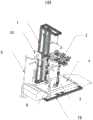
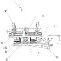
| CN107157712B (en)* | 2017-06-20 | 2023-07-11 | 深圳市瀚翔生物医疗电子股份有限公司 | Rehabilitation device for lower limb training |
| CN107694013B (en)* | 2017-11-23 | 2023-05-23 | 航天科工智能机器人有限责任公司 | A weight-reducing support system for rehabilitation training of patients' lower limbs |
| CN107854281A (en)* | 2017-11-30 | 2018-03-30 | 湖南妙手机器人有限公司 | Lower limb rehabilitation robot |
| CN108210245A (en)* | 2018-01-09 | 2018-06-29 | 洛阳理工学院 | A kind of leg training healing robot |
| CN108042313B (en)* | 2018-01-12 | 2023-10-27 | 深圳市迈步机器人科技有限公司 | Pelvis exercise auxiliary structure |
| CN108245840A (en)* | 2018-01-12 | 2018-07-06 | 深圳市瀚翔生物医疗电子股份有限公司 | A kind of planer-type leg training rehabilitation equipment |
| CN108514494A (en)* | 2018-02-02 | 2018-09-11 | 上海交通大学 | Device for the training of postoperative gait rehabilitation |
| CN109223434B (en)* | 2018-08-06 | 2020-01-07 | 北京航空航天大学 | An exoskeleton rehabilitation robot |
| CN108853928A (en)* | 2018-09-10 | 2018-11-23 | 安庆中船柴油机有限公司 | A kind of healing robot |
| CN109846642A (en)* | 2019-01-23 | 2019-06-07 | 广西大学 | A hip width adjustment and locking mechanism for a gait training rehabilitation robot |
| CN110219591B (en)* | 2019-07-25 | 2024-04-26 | 桂林航天工业学院 | A walking device for engineering drilling equipment |
| CN110314068A (en)* | 2019-08-01 | 2019-10-11 | 台州市中心医院(台州学院附属医院) | Neural rehabilitation training device of shank that patient independently used |
| CN110974620B (en)* | 2019-12-12 | 2024-11-26 | 上海理工大学 | A mechanical virtual walking training aid device |
| CN110974633B (en)* | 2019-12-26 | 2025-07-29 | 上海金矢机器人科技有限公司 | Intelligent walking-assisting rehabilitation training robot |
| CN111297634B (en)* | 2020-03-04 | 2024-09-03 | 河南省祥和康复产业技术研究院有限责任公司 | Barrel gate type wet lower limb rehabilitation training device |
| CN111345969A (en)* | 2020-03-12 | 2020-06-30 | 泰信利美信息科技(常州)有限公司 | Traction device for orthopedics |
| CN111449910B (en)* | 2020-04-24 | 2022-03-11 | 李进梅 | Shank stretching device that orthopedics was used |
| CN111803334A (en)* | 2020-06-30 | 2020-10-23 | 山东管理学院 | A functional training device for a one-stop elderly care service center |
| US12016814B2 (en)* | 2020-10-05 | 2024-06-25 | Altimate Medical Holdings, Inc. | Carriable complex rehabilitation technology systems |
| CN112206471A (en)* | 2020-11-14 | 2021-01-12 | 南京浙溧智能制造研究院有限公司 | Gait rehabilitation training device for Parkinson patient |
| CN112826696A (en)* | 2020-12-24 | 2021-05-25 | 阁步(上海)医疗科技有限公司 | Three-freedom mechanical arm for lower limb rehabilitation training device |
| CN112826694A (en)* | 2020-12-24 | 2021-05-25 | 阁步(上海)医疗科技有限公司 | Base supporting device for lower limb rehabilitation training device |
| CN112826697A (en)* | 2020-12-24 | 2021-05-25 | 阁步(上海)医疗科技有限公司 | Lower limb rehabilitation training robot |
| CN113143701B (en)* | 2021-01-21 | 2023-01-10 | 河南省人民医院 | A walking aid device for rehabilitation of patients with neurological diseases |
| CN112891154B (en)* | 2021-03-03 | 2023-03-21 | 遂宁市中心医院 | A neural rehabilitation device for cerebral apoplexy patient |
| CN113081665A (en)* | 2021-03-22 | 2021-07-09 | 上海交通大学 | Exercise-assisted rehabilitation device |
| CN113143695B (en)* | 2021-04-15 | 2022-11-01 | 北航歌尔(潍坊)智能机器人有限公司 | Weight reduction device for rehabilitation training and limb rehabilitation system |
| CN113101145A (en)* | 2021-04-28 | 2021-07-13 | 泉州平旺科技有限公司 | Orthopedics is with injured patient's of shank massage device |
| CN113577669B (en)* | 2021-08-05 | 2022-07-22 | 无锡市第二人民医院 | A balance mechanism and a limb exercise device for chronic kidney disease rehabilitation |
| CN113750464B (en)* | 2021-08-10 | 2023-07-18 | 长治医学院 | Lower limb nerve rehabilitation evaluation and training equipment |
| CN113876526B (en)* | 2021-10-05 | 2023-05-26 | 罗东旭 | Artificial intelligence pelvis restoration physiotherapy system based on Internet of things and restoration method thereof |
| US20240407335A1 (en)* | 2021-10-13 | 2024-12-12 | Tekno Idea S.R.L. | Device for the treatment of the motility of quadruples |
| CN113855488B (en)* | 2021-10-26 | 2024-07-23 | 上海迈动医疗器械股份有限公司 | Novel recovered sky rail of drive formula |
| CN114224582B (en)* | 2021-12-06 | 2023-09-01 | 中国人民解放军北部战区总医院 | Orthopedic clinical nursing bracket and use method thereof |
| CN114028175B (en)* | 2021-12-14 | 2024-11-15 | 青岛市胶州中心医院 | A multifunctional physical therapy rehabilitation device for cardiology |
| CN114146363B (en)* | 2021-12-14 | 2022-08-30 | 国家康复辅具研究中心 | Walking aid training system and integrated control method thereof |
| CN114042292B (en)* | 2021-12-21 | 2023-02-03 | 永城市人民医院 | Cerebral infarction patient lower limb rehabilitation training device |
| CN114392115A (en)* | 2021-12-27 | 2022-04-26 | 葛保国 | Limb training device for severe medical department |
| CN114681270B (en)* | 2022-04-11 | 2023-07-14 | 内蒙古工业大学 | A lower extremity exoskeleton for paraplegic and hemiplegic patients |
| CN115350443B (en)* | 2022-09-06 | 2023-08-22 | 浙江中医药大学附属第三医院 | Rehabilitation training device and application method thereof |
| CN115887173A (en)* | 2022-10-12 | 2023-04-04 | 美利威瑟(金华)科技发展有限责任公司 | Self-learning-based exoskeleton rehabilitation training device for disabled people |
| CN117159330B (en)* | 2023-10-17 | 2024-03-26 | 中国人民解放军总医院第二医学中心 | Department of neurology is with supplementary rehabilitation training device of low limbs |
Citations (3)
| Publication number | Priority date | Publication date | Assignee | Title |
|---|---|---|---|---|
| KR101416068B1 (en)* | 2013-04-25 | 2014-07-08 | 세종대학교산학협력단 | Walk Supporting Apparatus Having Walk Practicing Device |
| CN105392461A (en)* | 2013-06-21 | 2016-03-09 | 浩康股份公司 | Apparatus for automated walking training |
| CN105832496A (en)* | 2016-03-17 | 2016-08-10 | 合肥工业大学 | Novel lower extremity exoskeleton rehabilitation training device and training method |
Family Cites Families (49)
| Publication number | Priority date | Publication date | Assignee | Title |
|---|---|---|---|---|
| US4635875A (en)* | 1984-01-19 | 1987-01-13 | Apple Merrill K | Cable pulling device |
| US4620703A (en)* | 1984-10-12 | 1986-11-04 | Greenhut Paul M | Exercise apparatus |
| US4724827A (en)* | 1985-01-10 | 1988-02-16 | Schenck Robert R | Dynamic traction device |
| US5667461A (en)* | 1994-07-06 | 1997-09-16 | Hall; Raymond F. | Ambulatory traction assembly |
| US6123649A (en)* | 1998-02-13 | 2000-09-26 | Lee; R. Clayton | Resistance apparatus for connection to a human body |
| WO2001014018A1 (en)* | 1999-08-20 | 2001-03-01 | The Regents Of The University Of California | Method, apparatus and system for automation of body weight support training (bwst) of biped locomotion over a treadmill using a programmable stepper device (psd) operating like an exoskeleton drive system from a fixed base |
| US20040204294A2 (en)* | 2000-12-29 | 2004-10-14 | William Wilkinson | Exercise device for exercising upper body simultaneously with lower body exercise |
| US6796926B2 (en)* | 2001-08-22 | 2004-09-28 | The Regents Of The University Of California | Mechanism for manipulating and measuring legs during stepping |
| US7125388B1 (en)* | 2002-05-20 | 2006-10-24 | The Regents Of The University Of California | Robotic gait rehabilitation by optimal motion of the hip |
| US6837830B2 (en)* | 2002-11-01 | 2005-01-04 | Mark W. Eldridge | Apparatus using multi-directional resistance in exercise equipment |
| US20040116839A1 (en)* | 2002-12-13 | 2004-06-17 | New Mexico Technical Research Foundation | Gait training apparatus |
| US10286279B2 (en)* | 2003-07-16 | 2019-05-14 | Vertimax, Llc | Lateral training system and method |
| US7331906B2 (en)* | 2003-10-22 | 2008-02-19 | Arizona Board Of Regents | Apparatus and method for repetitive motion therapy |
| US7494450B2 (en)* | 2004-05-14 | 2009-02-24 | Solomon Richard D | Variable unweighting and resistance training and stretching apparatus for use with a cardiovascular or other exercise device |
| US9616274B2 (en)* | 2005-03-01 | 2017-04-11 | Michael A. Wehrell | Swing training apparatus and method |
| US7998040B2 (en)* | 2005-04-11 | 2011-08-16 | The Regents Of The University Of Colorado | Force assistance device for walking rehabilitation therapy |
| PL1874239T3 (en)* | 2005-04-13 | 2014-10-31 | Univ California | Semi-powered lower extremity exoskeleton |
| US7556606B2 (en)* | 2006-05-18 | 2009-07-07 | Massachusetts Institute Of Technology | Pelvis interface |
| US8152699B1 (en)* | 2008-06-19 | 2012-04-10 | Arrowhead Center, Inc. | Apparatus and method for reduced-gravity simulation |
| US7887471B2 (en)* | 2008-11-25 | 2011-02-15 | Mcsorley Tyrone G | Neuromuscular training apparatus and method of use |
| IT1393365B1 (en)* | 2009-03-20 | 2012-04-20 | Dinon | ROBOT MOTOR REHABILITATION DEVICE |
| CN101536955B (en)* | 2009-04-21 | 2011-01-05 | 清华大学 | Vertical follow-up type lightened walking rehabilitation training robot |
| JP5507224B2 (en)* | 2009-12-02 | 2014-05-28 | 学校法人 中村産業学園 | Walking assistance robot |
| US8608479B2 (en)* | 2010-05-07 | 2013-12-17 | The University Of Kansas | Systems and methods for facilitating gait training |
| DE202010015329U1 (en)* | 2010-11-12 | 2011-02-24 | Harrer, Franz | Treadmill ergometer with adapted train and measuring units for therapeutic applications and for the gear school as well as running training |
| WO2013009749A1 (en)* | 2011-07-11 | 2013-01-17 | Powerblock Holdings, Inc. | Exercise machine for providing weight lifting exercises similar to those provided by a free weight barbell |
| KR101289005B1 (en)* | 2012-02-08 | 2013-07-23 | 주식회사 피앤에스미캐닉스 | Walking training apparatus |
| US20140100491A1 (en)* | 2012-10-05 | 2014-04-10 | Jianjuen Hu | Lower Extremity Robotic Rehabilitation System |
| ITRM20120482A1 (en)* | 2012-10-09 | 2014-04-10 | Uni Campus Bio Medico Di Rom A | ROBOTIC DEVICE FOR ASSISTANCE AND REHABILITATION OF LOWER LIMBS. |
| US20140121071A1 (en)* | 2012-10-31 | 2014-05-01 | Icon Health & Fitness, Inc. | Movable Pulley Systems, Methods and Devices for Exercise Machines |
| CN103892987B (en)* | 2012-12-25 | 2015-11-25 | 上海璟和技创机器人有限公司 | A kind of lower limbs rehabilitation training robot |
| CN103349596B (en)* | 2013-07-19 | 2015-12-30 | 马放 | There is the liftable of body-building function, flexible, rotation remote control electric self-aid vehicle |
| US9638163B2 (en)* | 2014-02-20 | 2017-05-02 | General Electric Company | Methods and systems for removing and/or installing wind turbine rotor blades |
| US9421144B2 (en)* | 2014-03-07 | 2016-08-23 | Eugene Kalinowski | Motorized air walker and suspension system for paralyzed persons |
| EP3133998B1 (en)* | 2014-04-21 | 2019-07-03 | The Trustees of Columbia University in the City of New York | Human movement research, therapeutic, and diagnostic devices, methods, and systems |
| US9662526B2 (en)* | 2014-04-21 | 2017-05-30 | The Trustees Of Columbia University In The City Of New York | Active movement training devices, methods, and systems |
| CN104107131B (en)* | 2014-07-01 | 2016-03-30 | 西安交通大学 | An adaptive support and weight reduction device for a lower limb exoskeleton rehabilitation robot |
| US10500122B2 (en)* | 2014-07-09 | 2019-12-10 | Hocoma Ag | Apparatus for gait training |
| KR101680740B1 (en)* | 2015-08-31 | 2016-11-30 | 한국과학기술연구원 | Recognition method of human walking speed intention from surface electromyogram signals of plantar flexor and walking speed control method of a lower-limb exoskeleton robot |
| EA030027B1 (en)* | 2015-12-23 | 2018-06-29 | Общество С Ограниченной Ответственностью "Кинидекс" | System and method for restoring human motor activity |
| US10870033B2 (en)* | 2016-05-13 | 2020-12-22 | Neuromobility Llc | Device with reciprocating upper extremity support assemblies |
| US20180125738A1 (en)* | 2016-05-25 | 2018-05-10 | Carnegie Mellon University | Exoskeleton device and control system |
| US10292892B2 (en)* | 2016-09-12 | 2019-05-21 | Lunghwa University Of Science And Technology | Pneumatic lower extremity gait rehabilitation training system |
| US9789023B1 (en)* | 2016-09-29 | 2017-10-17 | Lunghwa University Of Science And Technology | Multi-function lower limb ambulation rehabilitation and walking assist device |
| JP6458795B2 (en)* | 2016-12-08 | 2019-01-30 | トヨタ自動車株式会社 | Walking training device |
| CN106726358A (en)* | 2017-03-16 | 2017-05-31 | 沈阳艾克申机器人技术开发有限责任公司 | A kind of vertical lower limbs rehabilitation training robot |
| CN107260483B (en)* | 2017-05-22 | 2018-06-26 | 华中科技大学 | A kind of link-type lower limb exoskeleton rehabilitation robot |
| CN207837831U (en)* | 2017-06-20 | 2018-09-11 | 深圳市瀚翔生物医疗电子股份有限公司 | A kind of leg training rehabilitation equipment |
| CN107157712B (en)* | 2017-06-20 | 2023-07-11 | 深圳市瀚翔生物医疗电子股份有限公司 | Rehabilitation device for lower limb training |
- 2017
- 2017-06-20CNCN201710471494.5Apatent/CN107157712B/enactiveActive
- 2018
- 2018-03-12USUS16/469,649patent/US11166866B2/enactiveActive
- 2018-03-12WOPCT/CN2018/078705patent/WO2018233322A1/ennot_activeCeased
- 2018-03-12EPEP18821348.2Apatent/EP3643286A4/ennot_activeWithdrawn
Patent Citations (3)
| Publication number | Priority date | Publication date | Assignee | Title |
|---|---|---|---|---|
| KR101416068B1 (en)* | 2013-04-25 | 2014-07-08 | 세종대학교산학협력단 | Walk Supporting Apparatus Having Walk Practicing Device |
| CN105392461A (en)* | 2013-06-21 | 2016-03-09 | 浩康股份公司 | Apparatus for automated walking training |
| CN105832496A (en)* | 2016-03-17 | 2016-08-10 | 合肥工业大学 | Novel lower extremity exoskeleton rehabilitation training device and training method |
Also Published As
| Publication number | Publication date |
|---|---|
| WO2018233322A1 (en) | 2018-12-27 |
| EP3643286A4 (en) | 2021-03-31 |
| EP3643286A1 (en) | 2020-04-29 |
| CN107157712A (en) | 2017-09-15 |
| US20200100977A1 (en) | 2020-04-02 |
| US11166866B2 (en) | 2021-11-09 |
Similar Documents
| Publication | Publication Date | Title |
|---|---|---|
| CN107157712B (en) | Rehabilitation device for lower limb training | |
| CN207370865U (en) | A kind of vertical lower limbs rehabilitation training robot | |
| CN205145027U (en) | Seat movable low limbs ectoskeleton rehabilitation training device | |
| CN106823289A (en) | A kind of healthy trainer of pose adjustable lower limb | |
| CN206745869U (en) | A kind of healthy trainer of pose adjustable lower limb | |
| CN108245840A (en) | A kind of planer-type leg training rehabilitation equipment | |
| CN103230331A (en) | Foldable and orbital transfer upper and lower limb coordination exercise training chair | |
| CN103316452B (en) | Foldable, track-changeable upper and lower limb coordination movement training mechanism | |
| CN207341905U (en) | One kind can survey the healthy training device of lower limb in real time | |
| CN108969296A (en) | A kind of lower limb rehabilitation robot | |
| CN107822834A (en) | A kind of pedal lower limb rehabilitation robot of bilateral independent control | |
| CN206730382U (en) | A kind of healthy image training robot of more poses | |
| CN207837831U (en) | A kind of leg training rehabilitation equipment | |
| CN107157704B (en) | Pelvis exercise auxiliary structure | |
| CN106890430A (en) | A kind of measurable many healthy image training robots of pose in real time | |
| CN206715172U (en) | A kind of measurable more healthy image training robots of pose in real time | |
| CN203315647U (en) | Track-changeable upper limb and lower limb coordinate exercise training mechanism with moving pair | |
| CN207838144U (en) | A kind of planer-type leg training rehabilitation equipment | |
| CN103463796A (en) | Adjustable-trajectory limb health training device with sliding pair | |
| CN209347555U (en) | A kind of intelligence weight reducing device | |
| CN103976851A (en) | Self-rehabilitation training instrument for shoulder joints | |
| CN110251364A (en) | A robot for upper limb rehabilitation training | |
| CN203315281U (en) | Upper limb and lower limb coordination exercise training chair capable of being folded and changing rails | |
| CN207979955U (en) | A kind of pelvic movement supplementary structure | |
| CN108042313B (en) | Pelvis exercise auxiliary structure |
Legal Events
| Date | Code | Title | Description |
|---|---|---|---|
| PB01 | Publication | ||
| PB01 | Publication | ||
| SE01 | Entry into force of request for substantive examination | ||
| SE01 | Entry into force of request for substantive examination | ||
| GR01 | Patent grant | ||
| GR01 | Patent grant | ||
| CP03 | Change of name, title or address | ||
| CP03 | Change of name, title or address | Address after:Room 301, Building A, Huayuan City Digital Building, No. 1079 Nanhai Avenue, Nanshan District, Shenzhen City, Guangdong Province, 518000 Patentee after:Shenzhen Hanxiang Brain Science and Technology Co.,Ltd. Country or region after:China Patentee after:SHENZHEN MILEBOT ROBOTICS Co.,Ltd. Address before:Room 301, Building A, Huayuan City Digital Building, No. 1079 Nanhai Avenue, Nanshan District, Shenzhen City, Guangdong Province, 518000 Patentee before:SHENZHEN HANIX UNITED, Ltd. Country or region before:China Patentee before:SHENZHEN MILEBOT ROBOTICS Co.,Ltd. | |
| TR01 | Transfer of patent right | ||
| TR01 | Transfer of patent right | Effective date of registration:20240312 Address after:518000, Zone B, 2nd Floor, Juyou Entrepreneurship Center (Phoenix City Building), No. 15 Keji North Road, Songpingshan Community, Xili Street, Nanshan District, Shenzhen City, Guangdong Province (one photo multiple site enterprise) Patentee after:SHENZHEN YINGZHI TECHNOLOGY Co.,Ltd. Country or region after:China Address before:Room 301, Building A, Huayuan City Digital Building, No. 1079 Nanhai Avenue, Nanshan District, Shenzhen City, Guangdong Province, 518000 Patentee before:Shenzhen Hanxiang Brain Science and Technology Co.,Ltd. Country or region before:China Patentee before:SHENZHEN MILEBOT ROBOTICS Co.,Ltd. |