CN107148719B - System and method for power transmission - Google Patents
System and method for power transmissionDownload PDFInfo
- Publication number
- CN107148719B CN107148719BCN201580055444.8ACN201580055444ACN107148719BCN 107148719 BCN107148719 BCN 107148719BCN 201580055444 ACN201580055444 ACN 201580055444ACN 107148719 BCN107148719 BCN 107148719B
- Authority
- CN
- China
- Prior art keywords
- transmitter
- power
- receiver
- coil
- wireless power
- Prior art date
- Legal status (The legal status is an assumption and is not a legal conclusion. Google has not performed a legal analysis and makes no representation as to the accuracy of the status listed.)
- Active
Links
Images


Classifications
- H—ELECTRICITY
- H02—GENERATION; CONVERSION OR DISTRIBUTION OF ELECTRIC POWER
- H02J—CIRCUIT ARRANGEMENTS OR SYSTEMS FOR SUPPLYING OR DISTRIBUTING ELECTRIC POWER; SYSTEMS FOR STORING ELECTRIC ENERGY
- H02J7/00—Circuit arrangements for charging or depolarising batteries or for supplying loads from batteries
- H02J7/0042—Circuit arrangements for charging or depolarising batteries or for supplying loads from batteries characterised by the mechanical construction
- H—ELECTRICITY
- H02—GENERATION; CONVERSION OR DISTRIBUTION OF ELECTRIC POWER
- H02J—CIRCUIT ARRANGEMENTS OR SYSTEMS FOR SUPPLYING OR DISTRIBUTING ELECTRIC POWER; SYSTEMS FOR STORING ELECTRIC ENERGY
- H02J50/00—Circuit arrangements or systems for wireless supply or distribution of electric power
- H02J50/005—Mechanical details of housing or structure aiming to accommodate the power transfer means, e.g. mechanical integration of coils, antennas or transducers into emitting or receiving devices
- H—ELECTRICITY
- H02—GENERATION; CONVERSION OR DISTRIBUTION OF ELECTRIC POWER
- H02J—CIRCUIT ARRANGEMENTS OR SYSTEMS FOR SUPPLYING OR DISTRIBUTING ELECTRIC POWER; SYSTEMS FOR STORING ELECTRIC ENERGY
- H02J50/00—Circuit arrangements or systems for wireless supply or distribution of electric power
- H02J50/10—Circuit arrangements or systems for wireless supply or distribution of electric power using inductive coupling
- H02J50/12—Circuit arrangements or systems for wireless supply or distribution of electric power using inductive coupling of the resonant type
- H—ELECTRICITY
- H02—GENERATION; CONVERSION OR DISTRIBUTION OF ELECTRIC POWER
- H02J—CIRCUIT ARRANGEMENTS OR SYSTEMS FOR SUPPLYING OR DISTRIBUTING ELECTRIC POWER; SYSTEMS FOR STORING ELECTRIC ENERGY
- H02J50/00—Circuit arrangements or systems for wireless supply or distribution of electric power
- H02J50/40—Circuit arrangements or systems for wireless supply or distribution of electric power using two or more transmitting or receiving devices
- H—ELECTRICITY
- H02—GENERATION; CONVERSION OR DISTRIBUTION OF ELECTRIC POWER
- H02J—CIRCUIT ARRANGEMENTS OR SYSTEMS FOR SUPPLYING OR DISTRIBUTING ELECTRIC POWER; SYSTEMS FOR STORING ELECTRIC ENERGY
- H02J50/00—Circuit arrangements or systems for wireless supply or distribution of electric power
- H02J50/80—Circuit arrangements or systems for wireless supply or distribution of electric power involving the exchange of data, concerning supply or distribution of electric power, between transmitting devices and receiving devices
- H—ELECTRICITY
- H02—GENERATION; CONVERSION OR DISTRIBUTION OF ELECTRIC POWER
- H02J—CIRCUIT ARRANGEMENTS OR SYSTEMS FOR SUPPLYING OR DISTRIBUTING ELECTRIC POWER; SYSTEMS FOR STORING ELECTRIC ENERGY
- H02J7/00—Circuit arrangements for charging or depolarising batteries or for supplying loads from batteries
- H02J7/007—Regulation of charging or discharging current or voltage
- H02J7/00712—Regulation of charging or discharging current or voltage the cycle being controlled or terminated in response to electric parameters
- H02J7/00714—Regulation of charging or discharging current or voltage the cycle being controlled or terminated in response to electric parameters in response to battery charging or discharging current
- H—ELECTRICITY
- H04—ELECTRIC COMMUNICATION TECHNIQUE
- H04B—TRANSMISSION
- H04B5/00—Near-field transmission systems, e.g. inductive or capacitive transmission systems
- H04B5/20—Near-field transmission systems, e.g. inductive or capacitive transmission systems characterised by the transmission technique; characterised by the transmission medium
- H04B5/24—Inductive coupling
- H—ELECTRICITY
- H04—ELECTRIC COMMUNICATION TECHNIQUE
- H04B—TRANSMISSION
- H04B5/00—Near-field transmission systems, e.g. inductive or capacitive transmission systems
- H04B5/70—Near-field transmission systems, e.g. inductive or capacitive transmission systems specially adapted for specific purposes
- H04B5/79—Near-field transmission systems, e.g. inductive or capacitive transmission systems specially adapted for specific purposes for data transfer in combination with power transfer
Landscapes
- Engineering & Computer Science (AREA)
- Power Engineering (AREA)
- Computer Networks & Wireless Communication (AREA)
- Signal Processing (AREA)
- Charge And Discharge Circuits For Batteries Or The Like (AREA)
- Near-Field Transmission Systems (AREA)
Abstract
Description
Translated fromChinese技术领域technical field
本发明属于无线或感应功率传输领域。更具体地,但非排他地,本发明涉及用于消费电子设备的感应功率传输的系统和方法。The present invention belongs to the field of wireless or inductive power transmission. More specifically, but not exclusively, the present invention relates to systems and methods for inductive power transfer for consumer electronic devices.
背景技术Background technique
IPT技术是一个日益发展的领域,IPT系统现在用于一系列应用且具有各种配置。一种这类应用是IPT系统在所谓的“充电垫”或板中的使用。这样的充电垫通常将提供平面充电表面,便携式电子设备(诸如智能电话)可以放置在该充电表面上而被无线充电或供电。IPT technology is a growing field and IPT systems are now used in a range of applications and in various configurations. One such application is the use of IPT systems in so-called "charging pads" or plates. Such charging pads will typically provide a flat charging surface upon which portable electronic devices, such as smartphones, can be placed to be wirelessly charged or powered.
通常,充电垫将包括发射器,发射器具有与充电垫的平面充电表面平行布置的一个或更多个功率传输线圈。发射器驱动发射线圈,使得发射线圈紧邻平面表面产生时变磁场。当便携式电子设备放置在平面表面上或附近时,时变磁场将在与设备相关联的合适的接收器(例如,结合到设备本身中的接收器)的接收线圈中感应出交流电。然后接收到的功率可以用于对电池充电,或为设备或一些其他负载供电。Typically, the charging pad will include a transmitter with one or more power transfer coils arranged parallel to the planar charging surface of the charging pad. The transmitter drives the transmit coil so that the transmit coil produces a time-varying magnetic field in close proximity to the planar surface. When the portable electronic device is placed on or near a flat surface, the time-varying magnetic field will induce an alternating current in the receive coil of a suitable receiver associated with the device (eg, a receiver incorporated into the device itself). The received power can then be used to charge a battery, or power a device or some other load.
与充电垫设计相关的问题是确保感应功率传输充分有效。一种方法是要求发射线圈和接收线圈之间的精确对准。这可以例如通过以下来实现:在平面充电表面上做标记或凹痕,使得当用户将设备放置在充电垫上时,可以保证线圈之间的对准。然而,这种方法并不理想,因为需要用户将他们的设备小心地放置在充电垫上。A problem associated with charging pad design is ensuring that inductive power transfer is sufficiently efficient. One approach is to require precise alignment between the transmit and receive coils. This can be achieved, for example, by marking or indenting the flat charging surface so that when the user places the device on the charging pad, alignment between the coils can be guaranteed. However, this approach is not ideal as it requires users to carefully place their devices on the charging pad.
与充电垫设计相关的另一个问题是能够以有效和成本有效的方式同时对多个设备充电。一些常规设计使用与充电垫的整个表面相对应的单个大发射线圈。在这种情况下,一个或更多个设备可以放置在充电垫的表面上的任何地方。这就用户可以将设备放置在充电垫上来讲给予了更多的自由。然而,由大发射线圈产生的磁场可能是不均匀的,存在朝向充电垫的中心的“弱点”。此外,由于整个表面被“供电”,可能的是,表面未被正在充电设备覆盖的任何部分可能存在安全隐患。Another issue associated with charging pad design is the ability to charge multiple devices simultaneously in an efficient and cost-effective manner. Some conventional designs use a single large transmit coil that corresponds to the entire surface of the charging pad. In this case, one or more devices can be placed anywhere on the surface of the charging pad. This gives the user more freedom in terms of placing the device on the charging pad. However, the magnetic field produced by the large transmit coil can be non-uniform, with a "weak point" towards the center of the charging pad. Furthermore, since the entire surface is "powered", it is possible that any part of the surface not covered by the device being charged may be a safety hazard.
用于多设备充电的另一常规方法是具有较小发射线圈的阵列。为了提供有效和安全的功率传输,充电垫使用合适的检测机构来检测设备的位置,并激活最接近的一个发射线圈或多个发射线圈。虽然这就用户可以放置设备的位置来讲给予了更多自由,但是像单线圈设计,相邻发射线圈之间的边界可能由于相邻线圈的抵消效应而导致弱点,由此接收器不能接收足够的功率。Another conventional method for multi-device charging is an array with smaller transmit coils. To provide efficient and safe power transfer, the charging pad uses a suitable detection mechanism to detect the position of the device and activate the closest transmitter coil or coils. While this gives more freedom in terms of where the user can place the device, like single-coil designs, the boundaries between adjacent transmit coils can lead to weaknesses due to the canceling effect of adjacent coils, whereby the receiver cannot receive enough of power.
当非接收器进入发射器的范围中时另一个问题出现了,不需要的电流(因此热)在其中被感应出来。这些非接收器通常被称为寄生负载或异物。通常可以检测接收器设备的存在,但是也可能需要将接收器识别为与特定发射器兼容。试图将功率传输到不兼容的接收器可能导致无效的功率传输(因此,不期望的能量损耗),或者发射器和/或接收器故障。Another problem arises when the non-receiver comes into range of the transmitter, where unwanted current (and therefore heat) is induced. These non-receivers are often referred to as parasitic loads or foreign objects. It is usually possible to detect the presence of a receiver device, but it may also be necessary to identify the receiver as compatible with a particular transmitter. Attempting to transfer power to an incompatible receiver may result in ineffective power transfer (hence, undesired energy loss), or transmitter and/or receiver failure.
对上述问题的一种明显的解决方案是使发射器包括手动操作的电源开关。虽然这提供了用于控制何时应当给发射器供电的方法,但是它破坏了许多IPT系统的目标-便利性。它还需要用户在移除接收器时手动关闭发射器,并且不适应在用户不知情的情况下可能被引入发射器附近的任何寄生负载。An obvious solution to the above problem is for the transmitter to include a manually operated power switch. While this provides a method for controlling when the transmitter should be powered, it defeats the goal of many IPT systems - convenience. It also requires the user to manually turn off the transmitter when the receiver is removed, and does not accommodate any parasitic loads that may be introduced near the transmitter without the user's knowledge.
本发明提供一种感应功率传输系统和方法,其对多设备供电来讲实现了可靠且有效的无线功率传输,或者至少为公众提供了有用的选择。The present invention provides an inductive power transfer system and method that enables reliable and efficient wireless power transfer for powering multiple devices, or at least provides the public with a useful choice.
发明内容SUMMARY OF THE INVENTION
根据一个示例性实施例,提供一种功率传输系统以及操作该系统的方法。该系统包括功率发射器和功率接收器。功率发射器具有多个发射器线圈,在控制器的控制下能够选择性地使所述多个发射器线圈以多种模式将功率传送到功率接收器的接收器线圈。控制器被配置为检测功率接收器的特性,以控制功率传输的模式。According to an exemplary embodiment, a power transfer system and method of operating the system are provided. The system includes a power transmitter and a power receiver. The power transmitter has a plurality of transmitter coils that can be selectively caused to transmit power to the receiver coils of the power receiver in various modes under the control of the controller. The controller is configured to detect characteristics of the power receiver to control the mode of power transfer.
根据另一个示例性实施例,提供一种功率传输系统,包括功率发射器和至少一个功率接收器,功率发射器具有多个发射器线圈,在控制器的控制下能够选择性地使所述多个发射器线圈以多种模式将功率传送到所述至少一个功率接收器的接收器线圈,其中,控制器被配置为检测功率接收器的特性,以控制功率传输的模式。According to another exemplary embodiment, there is provided a power transfer system including a power transmitter and at least one power receiver, the power transmitter having a plurality of transmitter coils, the plurality of which can be selectively enabled under the control of a controller The transmitter coils deliver power to the receiver coils of the at least one power receiver in multiple modes, wherein the controller is configured to detect characteristics of the power receiver to control the mode of power transfer.
功率接收器的特性可以包括:功率接收器是否包括用于控制到接收器的负载的功率流的电路。Characteristics of the power receiver may include whether the power receiver includes circuitry for controlling power flow to the receiver's load.
控制器可以被配置为与功率接收器通信,以及从功率接收器接收关于所述特性的信息。控制器可以被配置为通过对在功率发射器与功率接收器之间经由电磁感应传送的功率信号的调制来与功率接收器通信。The controller may be configured to communicate with the power receiver and to receive information about the characteristic from the power receiver. The controller may be configured to communicate with the power receiver by modulating a power signal communicated between the power transmitter and the power receiver via electromagnetic induction.
功率发射器可以包括物体检测器,物体检测器可以设置用于在由物体检测线圈感应的磁场内检测物体。The power transmitter may comprise an object detector which may be arranged to detect the object within the magnetic field induced by the object detection coil.
控制器可以从在耦合的发射器线圈与接收器线圈之间传递的调制的功率信号提取接收器设备版本信息,以基于版本信息来控制功率传输的模式。The controller may extract receiver device version information from the modulated power signal communicated between the coupled transmitter coil and receiver coil to control the mode of power transfer based on the version information.
控制器还可以从在耦合的发射器线圈与接收器线圈之间传递的调制的功率信号提取接收器设备配置信息,以基于配置信息来控制功率传输的模式。要传送到接收器设备的最大功率和/或对接收器供电所需的发射器线圈的数量可以根据配置信息来控制。The controller may also extract receiver device configuration information from the modulated power signal communicated between the coupled transmitter coil and receiver coil to control the mode of power transfer based on the configuration information. The maximum power to be delivered to the receiver device and/or the number of transmitter coils required to power the receiver can be controlled according to configuration information.
在接收器定位阶段期间,在能量传输之前,控制器可以基于从接收器接收到的信息来选择性地控制发射器线圈中的哪一个或哪些被驱动,所述信息是关于对由接收器从驱动的发射器线圈接收到的信号强度的测量。在接收器定位阶段期间,控制电路可以顺序地将来自功率调节电路的驱动信号连接到每个功率发射线圈以激励每个线圈预定时间。During the receiver positioning phase, prior to energy transfer, the controller may selectively control which one or which of the transmitter coils is driven based on information received from the receiver regarding A measurement of the signal strength received by a driven transmitter coil. During the receiver positioning phase, the control circuit may sequentially connect a drive signal from the power conditioning circuit to each of the power transmit coils to energize each coil for a predetermined time.
根据另一个示例性实施例,提供一种用于给感应功率传输接收器供给功率的感应功率传输发射器,感应功率传输接收器具有一个或更多个接收器线圈,发射器包括:According to another exemplary embodiment, there is provided an inductive power transfer transmitter for powering an inductive power transfer receiver having one or more receiver coils, the transmitter comprising:
i.多个发射器线圈;i. Multiple transmitter coils;
ii.功率调节电路,所述功率调节电路用于在被驱动时将驱动信号供应给发射器线圈;以及ii. a power conditioning circuit for supplying a drive signal to the transmitter coil when driven; and
iii.控制电路,所述控制电路基于由发射器从接收器接收到的信息来选择性地控制发射器线圈中的哪一个或哪些被功率调节电路驱动,所述信息是关于对由接收器线圈从驱动的发射器线圈接收到的信号强度的测量。iii. A control circuit that selectively controls which one or which of the transmitter coils is driven by the power conditioning circuit based on information received by the transmitter from the receiver, the information being A measurement of the received signal strength from a driven transmitter coil.
在接收器定位阶段期间,控制电路顺序地将来自功率调节电路的驱动信号连接到每个功率发射线圈以激励每个线圈预定时间。预定时间对应于用于接收信号强度包的预期接收时间。During the receiver positioning phase, the control circuit sequentially connects a drive signal from the power conditioning circuit to each of the power transmit coils to energize each coil for a predetermined time. The predetermined time corresponds to the expected reception time for receiving the signal strength packet.
控制电路可以将响应于线圈被驱动而从接收器接收到的信息与驱动的线圈关联,以选择发射器线圈中的哪一个或哪些要被驱动。通信模块可以检测对在耦合的发射器线圈与接收器线圈之间传递的功率信号的调制,以对发射器和接收器线圈对之间的耦合进行测量,优选地,通过从接收器发送来的信号强度包提取信号强度值来对发射器和接收器线圈对之间的耦合进行测量。The control circuit can correlate information received from the receiver in response to the coils being driven with the driven coils to select which one or which of the transmitter coils is to be driven. The communication module can detect the modulation of the power signal passed between the coupled transmitter coil and receiver coil to measure the coupling between the transmitter and receiver coil pair, preferably by a signal sent from the receiver. The signal strength packet extracts signal strength values to measure the coupling between the transmitter and receiver coil pairs.
在选择发射器线圈中的一个或多个之后,发射器线圈中的所述一个或多个被激励长于预定时间,以允许从接收器接收另外的包。控制电路可以选择一个或更多个发射器线圈,以给接收器供给功率。可以选择具有最高关联信号强度值的单个发射器线圈,或者作为具有最高关联信号强度值的发射器线圈和具有次高关联信号强度值的发射器线圈的两个或更多个发射器线圈。After selecting one or more of the transmitter coils, the one or more of the transmitter coils are energized for longer than a predetermined time to allow additional packets to be received from the receiver. The control circuit may select one or more transmitter coils to power the receiver. Either a single transmitter coil with the highest associated signal strength value, or two or more transmitter coils as the transmitter coil with the highest associated signal strength value and the transmitter coil with the next highest associated signal strength value may be selected.
控制电路可以响应于包含在由发射器接收到的信息中的功率接收器的特性来控制功率调制电路。The control circuit may control the power modulation circuit in response to the characteristics of the power receiver contained in the information received by the transmitter.
发射器可以包括物体检测系统,以及控制系统可以在物体检测系统检测物体时激励发射器线圈。The transmitter may include an object detection system, and the control system may energize the transmitter coil when the object detection system detects an object.
通信模块可以从在耦合的发射器线圈与接收器线圈之间传递的调制信号提取接收器标识信息,以及基于标识信息来控制功率调节电路的操作。The communication module may extract receiver identification information from the modulated signal communicated between the coupled transmitter coil and receiver coil, and control operation of the power conditioning circuit based on the identification information.
根据另一个示例性实施例,提供了一种在IPT功率系统中选择性地驱动一个或更多个发射器线圈的方法,IPT功率系统包括具有多个发射器线圈的IPT功率发射器和具有一个或更多个接收器线圈的功率接收器的,该方法包括以下步骤:According to another exemplary embodiment, a method of selectively driving one or more transmitter coils in an IPT power system is provided, the IPT power system including an IPT power transmitter having a plurality of transmitter coils and having a of a power receiver of or more receiver coils, the method comprising the steps of:
a.在接收器定位阶段期间,顺序地驱动功率发射线圈以激励每个线圈预定时间;a. During the receiver positioning phase, sequentially driving the power transmitting coils to excite each coil for a predetermined time;
b.检测接收器的一个或更多个接收器线圈的激励,以及响应于此,从接收器向发射器发送信号强度信息;b. Detecting excitation of one or more receiver coils of the receiver and, in response thereto, transmitting signal strength information from the receiver to the transmitter;
c.将接收到的信号强度信息与激励的发射器线圈关联;以及c. Correlate the received signal strength information with the energized transmitter coil; and
d.基于与每个发射器线圈关联的信号强度信息来确定在功率传输期间驱动哪个线圈或哪些线圈。d. Determine which coil or coils are driven during power transfer based on the signal strength information associated with each transmitter coil.
预定时间可以对应于用于接收信号强度包的预期接收时间。接收器可以通过对在功率发射器与功率接收器之间传送的功率信号的调制来将信号发送到发射器。信号强度信息可以以信号强度包来发送,信号强度包可以包括接收器标识信息。在接收器定位阶段之后,接收器标识信息可以以标识包发送给耦合的发射器。The predetermined time may correspond to an expected reception time for receiving the signal strength packet. The receiver may transmit the signal to the transmitter by modulating the power signal communicated between the power transmitter and the power receiver. The signal strength information may be sent in signal strength packets, which may include receiver identification information. Following the receiver location phase, receiver identification information may be sent to coupled transmitters in identification packets.
发射器可以基于接收器标识信息来确定版本信息。发射器的操作的模式可以根据版本信息来控制。标识包可以包括识别接收器的操作的模式的版本码。标识包还可以包括识别接收器的制造商的制造商码。标识包还可以包括唯一标识符。The transmitter may determine the version information based on the receiver identification information. The mode of operation of the transmitter can be controlled according to the version information. The identification packet may include a version code identifying the mode of operation of the receiver. The identification packet may also include a manufacturer code identifying the manufacturer of the receiver. The identification package may also include a unique identifier.
通信电路将接收器设备配置信息发送至耦合的接收器,优选地以配置包来将接收器设备配置信息发送至耦合的接收器。配置包可以包括要被传送的最大功率。功率发射器可以根据包含在由发射器接收到的信息中的功率接收器的特性来给功率接收器供给功率。The communication circuit sends the receiver device configuration information to the coupled receiver, preferably in a configuration packet to the coupled receiver. The configuration packet may include the maximum power to be transmitted. The power transmitter may supply power to the power receiver according to the characteristics of the power receiver contained in the information received by the transmitter.
在每个包包括接收器标识码,优选包括唯一码的情况下,功率传输的模式可以基于接收器标识码。Where each packet includes a receiver identification code, preferably a unique code, the mode of power transfer may be based on the receiver identification code.
根据另一个示例性实施例,提供一种感应功率传输接收器,包括:According to another exemplary embodiment, there is provided an inductive power transfer receiver comprising:
i.接收器线圈;i. Receiver coil;
ii.信号强度测量电路,所述信号强度测量电路用于测量由接收器线圈从感应功率传输发射器线圈接收到的信号的强度;以及ii. a signal strength measurement circuit for measuring the strength of a signal received by the receiver coil from the inductive power transfer transmitter coil; and
iii.通信电路,所述通信电路在从感应功率传输发射器线圈接收到功率时,将关于测量的信号强度和接收器标识信息的信号传送给感应功率传输发射器。iii. A communication circuit that, upon receiving power from the inductive power transfer transmitter coil, transmits a signal to the inductive power transfer transmitter regarding the measured signal strength and receiver identification information.
根据另一个示例性实施例,提供一种感应功率传输发射器,包括多个相邻的发射器线圈和由导磁材料形成的芯块,每个绕组限定中心开口,相邻线圈的中心开口限定公共开口,芯块被设置在至少一些公共开口内且在发射器线圈之上突出。According to another exemplary embodiment, there is provided an inductive power transfer transmitter comprising a plurality of adjacent transmitter coils and a core block formed of a magnetically permeable material, each winding defining a central opening, the central openings of the adjacent coils defining Common openings, core blocks are disposed within at least some of the common openings and protrude over the transmitter coils.
芯块从设置在线圈之下的导磁材料层突出。至少一些相邻的发射器线圈可以具有多层,并且它们的层可以交错。The core blocks protrude from the layer of magnetically conductive material disposed under the coils. At least some adjacent transmitter coils may have multiple layers, and their layers may be staggered.
根据另一个示例性实施例,提供一种发射器,其中,每个绕组限定中心开口,且相邻线圈的中心开口限定公共开口,以及其中,由导磁材料形成的芯块被设置在至少一些公共开口内。According to another exemplary embodiment, there is provided a transmitter wherein each winding defines a central opening and the central openings of adjacent coils define a common opening, and wherein a core block formed of a magnetically permeable material is provided in at least some of the in public openings.
每个芯块可以在发射器线圈的顶表面之上突出。多个发射器线圈可以被设置为:每个线圈具有多个绕组层,其中至少一些线圈偏移,且它们的层交错。芯块可以从设置在线圈之下的导磁材料层突出。Each core piece may protrude above the top surface of the transmitter coil. The multiple transmitter coils may be arranged with each coil having multiple winding layers, with at least some of the coils offset and their layers staggered. The core blocks may protrude from a layer of magnetically permeable material disposed below the coils.
至少一些线圈中的每层的绕组可以被形成为并联电连接的多个并联绕组。至少一些线圈中的每层的绕组可以被形成为并联电连接的三个并联绕组。至少一些并联绕组的径向位移可以在层与层之间改变。在一种设计中,成对的并联绕组在层与层之间在距离线圈中心最近与距离线圈中心最远之间交替。The windings of each layer in at least some of the coils may be formed as a plurality of parallel windings electrically connected in parallel. The windings of each layer in at least some of the coils may be formed as three parallel windings electrically connected in parallel. The radial displacement of at least some of the parallel windings may vary from layer to layer. In one design, pairs of parallel windings alternate between layers closest to the center of the coil and furthest from the center of the coil.
根据另一个示例性实施例,提供一种感应功率传输发射器,包括多个发射器线圈,其中,每个线圈由多个绕组层组成,以及其中,绕组被形成为并联电连接的多个并联绕组。According to another exemplary embodiment, there is provided an inductive power transfer transmitter comprising a plurality of transmitter coils, wherein each coil is composed of a plurality of winding layers, and wherein the windings are formed as a plurality of parallel electrical connections in parallel winding.
并联绕组可以形成在每层上且在层与层之间互连。至少一些线圈中的每层的绕组可以被形成为并联电连接的三个并联绕组。至少一些并联绕组的径向位移可以在层与层之间改变,诸如成对的并联绕组在层与层之间在最接近线圈中心和离线圈中心最远之间交替。Parallel windings may be formed on each layer and interconnected from layer to layer. The windings of each layer in at least some of the coils may be formed as three parallel windings electrically connected in parallel. The radial displacement of at least some of the parallel windings may vary from layer to layer, such as pairs of parallel windings alternating between layers closest to the center of the coil and farthest from the center of the coil.
每匝的并联绕组可以分布在绕组层之间,优选地,分布在两层之间。并联绕组还可以在层与层之间偏移。The parallel windings per turn may be distributed between the winding layers, preferably between two layers. Parallel windings can also be offset from layer to layer.
由导磁材料形成的芯块可以充分地延伸至每个线圈之上,以大幅减小绕组中的感应电流。芯块可以在每个绕组的顶部之上突出大约每个绕组的高度,或者在每个绕组的顶部之上突出大约或超过1mm。四个公共开口可以被限定在每个发射器线圈内以容纳芯块。空气间隙可以被设置在每个发射器线圈与每个芯块之间以减小发射器线圈中的感应电流。Core blocks formed of magnetically permeable material can extend sufficiently above each coil to substantially reduce induced currents in the windings. The core blocks may protrude above the top of each winding by about the height of each winding, or by about or more than 1 mm above the top of each winding. Four common openings may be defined within each transmitter coil to accommodate the pellets. An air gap may be provided between each transmitter coil and each core block to reduce induced currents in the transmitter coils.
根据另一个示例性实施例,提供一种具有多个发射器线圈的感应功率传输发射器,在控制器的控制下能够选择性地使所述多个发射器线圈以多种模式将功率传送到至少一个功率接收器的接收器线圈,其中,控制器被配置为检测功率接收器的特性,以控制功率传输的模式。According to another exemplary embodiment, there is provided an inductive power transfer transmitter having a plurality of transmitter coils that can be selectively caused, under the control of a controller, to transfer power in a plurality of modes to A receiver coil of at least one power receiver, wherein the controller is configured to detect characteristics of the power receiver to control the mode of power transfer.
功率接收器的特性可以包括:功率接收器是否包括用于控制到接收器的负载的功率流的电路。控制器可以被配置为诸如经由对在功率发射器与功率接收器之间由电磁感应传送的功率信号的调制,来与功率接收器通信,以及从功率接收器接收关于这种特性的信息。Characteristics of the power receiver may include whether the power receiver includes circuitry for controlling power flow to the receiver's load. The controller may be configured to communicate with the power receiver, such as via modulation of a power signal transmitted between the power transmitter and the power receiver by electromagnetic induction, and to receive information about such characteristics from the power receiver.
控制器可以从在耦合的发射器线圈与接收器线圈之间传递的调制的功率信号提取接收器设备版本信息,以及基于版本信息来控制功率传输的模式。The controller may extract receiver device version information from the modulated power signal communicated between the coupled transmitter coil and receiver coil, and control the mode of power transfer based on the version information.
要传送到接收器设备的最大功率和/或对接收器供电所需的发射器线圈的数量可以根据版本信息来控制。The maximum power to be delivered to the receiver device and/or the number of transmitter coils required to power the receiver can be controlled based on the version information.
根据另一个示例性实施例,提供一种感应功率传输接收器,包括:According to another exemplary embodiment, there is provided an inductive power transfer receiver comprising:
i.一个或更多个接收器线圈;以及i. one or more receiver coils; and
ii.通信电路,所述通信电路当在接收器线圈中从感应功率传输发射器线圈接收到功率时,将关于接收器的特性的信号传送给感应功率传输发射器。ii. A communication circuit that, when power is received in the receiver coil from the inductive power transfer transmitter coil, transmits a signal about the characteristics of the receiver to the inductive power transfer transmitter.
接收器可以包括用于控制到接收器的负载的功率流的功率流控制器,由通信电路传送的特性包括功率流控制特性。The receiver may include a power flow controller for controlling power flow to a load of the receiver, the characteristics communicated by the communication circuit including the power flow control characteristics.
接收器的特性可以包括版本信息,版本信息可以指示接收器的功率传输的模式。版本信息可以以信号强度包之后的包来发送。The characteristics of the receiver may include version information, which may indicate the mode of power transfer of the receiver. Version information may be sent in packets following the signal strength packet.
特性还可以包括配置信息,配置信息可以包括需要被驱动以给一个或更多个接收器线圈提供功率的发射器线圈的数量。Characteristics may also include configuration information, which may include the number of transmitter coils that need to be driven to provide power to one or more receiver coils.
关于从功率发射器接收到的功率信号的强度的信号强度信息可以在其他通信之前被发送。Signal strength information regarding the strength of the power signal received from the power transmitter may be sent prior to other communications.
需要知道,术语“包括”及其变型在不同的权限下可以具有排它性意义或包含性意义。出于本说明书的目的,除非另有说明,这些术语旨在具有包含性意义,即,它们将被认为表示包括该使用直接引用的所列出的组件,并且可能还包括其他未指出的组件或元件。It is to be understood that the term "comprising" and variations thereof can have an exclusive or inclusive meaning under different jurisdictions. For the purposes of this specification, unless otherwise stated, these terms are intended to have an inclusive meaning, i.e., they will be taken to mean that the listed component(s) to which this usage is directly referenced may also include other unspecified components or element.
本说明书中对任何现有技术的引用不构成承认这些现有技术形成公知常识的一部分。The citation of any prior art in this specification does not constitute an admission that such prior art forms part of the common general knowledge.
附图说明Description of drawings
附图示出了本发明的实施例,并且与上面给出的本发明的总体描述以及下面给出的实施例的详细描述一起用于解释本发明的原理,附图并入本说明书并构成其一部分。在附图中:The accompanying drawings illustrate embodiments of the invention and together with the general description of the invention given above and the detailed description of the embodiments given below serve to explain the principles of the invention, and are incorporated in and constitute the specification part. In the attached image:
图1图示了本发明的典型应用;Figure 1 illustrates a typical application of the present invention;
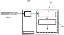
图2图示了本发明的无线功率传输系统的示例性配置;FIG. 2 illustrates an exemplary configuration of the wireless power transfer system of the present invention;
图3图示了系统的发射器的实施例;Figure 3 illustrates an embodiment of a transmitter of the system;
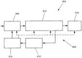
图4以框图形式示出了发射器的更详细示例;Figure 4 shows a more detailed example of a transmitter in block diagram form;
图5(A)-图5(D)示出了与物体检测测量有关的结果;Figures 5(A)-5(D) show results related to object detection measurements;
图6(A)-图6(E)图示了通信协议的数据和数据包结构;6(A)-FIG. 6(E) illustrate the data and packet structure of the communication protocol;
图7是通信处理块的框图;7 is a block diagram of a communication processing block;
图8图示了系统的接收器的实施例;Figure 8 illustrates an embodiment of a receiver of the system;
图9以框图形式示出了接收器的更详细示例;Figure 9 shows a more detailed example of a receiver in block diagram form;
图10是接收器的示例性形式的电路图;10 is a circuit diagram of an exemplary form of a receiver;
图11(A)图示了可操作来实现发射器的逆变器的功能的示例性电路的示意图;11(A) illustrates a schematic diagram of an exemplary circuit operable to implement the functionality of an inverter of a transmitter;
图11(B)图示了可操作来实现发射器的微处理器的功能的示例性电路的示意图;11(B) illustrates a schematic diagram of an exemplary circuit operable to implement the functionality of the transmitter's microprocessor;
图11(C)图示了可操作来实现发射器的功率调整器的功能的示例性电路的示意图;11(C) illustrates a schematic diagram of an exemplary circuit operable to implement the functions of a power regulator of a transmitter;
图11(D)图示了可操作来实现发射器的发射器线圈阵列的功能的示例性电路的示意图;11(D) illustrates a schematic diagram of an exemplary circuit operable to implement the functions of a transmitter coil array of a transmitter;
图11(E)图示了可操作来实现发射器的选择器的功能的示例性电路的示意图;11(E) illustrates a schematic diagram of an exemplary circuit operable to implement the functionality of a selector of a transmitter;
图11(F)图示了可操作来实现发射器的物体检测器的功能的示例性电路的示意图;11(F) illustrates a schematic diagram of an exemplary circuit operable to implement the functionality of an object detector of a transmitter;
图11(G)图示了可操作以实现发射器的通信模块的功能的示例性电路的示意图;FIG. 11(G) illustrates a schematic diagram of an exemplary circuit operable to implement the functions of a communication module of a transmitter;
图11(H)图示了用于改进发射器的通信模块的功能的示例性电路的示意图;11(H) illustrates a schematic diagram of an exemplary circuit for improving the functionality of the communication module of the transmitter;
图12(A)和图12(B)图示了可操作来实现接收器的整流器的功能的在点A和B上连接的示例性电路的示意图;Figures 12(A) and 12(B) illustrate schematic diagrams of exemplary circuits connected at points A and B operable to implement the function of the receiver's rectifier;
图12(C)图示了可操作以实现发射器的微处理器的功能的示例性电路的示意图;Figure 12(C) illustrates a schematic diagram of an exemplary circuit operable to implement the functions of the transmitter's microprocessor;
图12(D)图示了可操作以实现接收器的通信模块的功能的示例性电路的示意图;12(D) illustrates a schematic diagram of an exemplary circuit operable to implement the functionality of the communication module of the receiver;
图12(E)图示了可操作以实现接收器的电流感测电路的功能的示例性电路的示意图;12(E) illustrates a schematic diagram of an exemplary circuit operable to implement the functionality of a current sensing circuit of a receiver;
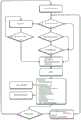
图13(A)-图13(C)是由发射器处理的控制顺序的流程图;13(A)-13(C) are flowcharts of the control sequence processed by the transmitter;
图14(A)-图14(C)是由接收器处理的控制顺序的流程图;14(A)-FIG. 14(C) are flowcharts of the control sequence processed by the receiver;
图15(A)-图15(C)图示了示例性的发射器线圈阵列;15(A)-15(C) illustrate exemplary transmitter coil arrays;
图15D至图15G图示了可以用于四层发射器线圈的示例性绕组图案;15D-15G illustrate exemplary winding patterns that may be used for a four-layer transmitter coil;
图15H和图15J图示了示例性的发射器线圈布置;15H and 15J illustrate exemplary transmitter coil arrangements;
图16是示例性发射器的分解图;16 is an exploded view of an exemplary transmitter;
图17图示了图16的发射器的分离的组件;Figure 17 illustrates separate components of the transmitter of Figure 16;
图18是图17中的视图的剖面图;Figure 18 is a cross-sectional view of the view in Figure 17;
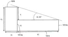
图19图示了铁磁突出部和PCB发射器线圈层之间的关系;以及Figure 19 illustrates the relationship between the ferromagnetic tabs and the PCB transmitter coil layers; and
图20(A)和图20(B)图示了系统的示例性的物体检测器的等效电路。20(A) and 20(B) illustrate the equivalent circuit of an exemplary object detector of the system.
具体实施方式Detailed ways
图1图示了本发明的典型应用100。无线功率传输系统100被示出为具有发射器或充电“板”102,发射器或充电“板”102具有设置在其上的多个消费电子设备104,使得设备的电负载或能量储存元件(例如,电池)可以以无线或非接触方式用电功率来充电。在所示示例中,使用发射器电子器件与接收器电子器件之间的松散耦合技术、经由电磁感应或感应功率传输(IPT)而在垫和设备之间提供电功率。然而,对于这样的系统,其他类型的无线功率传输也是可能的,例如,电容性功率传输。Figure 1 illustrates a
充电板102和设备104的发射器电子器件和接收器电子器件被配置为使得设备在板上的布置可以由用户任意选择,而不需要确保发射器电子器件(在板中或板上)与接收器电子器件(在设备中或设备上)的预定义对准,以用于功率传输以全部或有效的方式发生。此外,发射器被配置为独立地对如此设置的多个接收器设备充电。发射器和多个接收器之间的这种“空间自由”是基本上无限制的,并且被提供为如下所述。The transmitter electronics and receiver electronics of the
图2中图示了无线功率传输系统200的示例性配置。提供了发射器202,其被配置为向多个接收器204、206和208传输功率。在该示例中,示出了消费者设备配置的三个接收器,诸如图1中所示的放置在发射器“板”上的“智能电话”,然而本领域技术人员基于以下描述将理解,发射器的“板”可以缩放,以便适应并对相同类型或不同类型的两个或更多个接收器设备(例如,多个电话、平板手机、平板电脑、膝上计算机、其组合等)供电,它们中的每个具有各自的空间维度和功率水平,例如,智能电话可以需要约5瓦特至约7.5瓦特的功率,而平板电脑可以需要约15瓦特的功率以对各自的电池充电。An exemplary configuration of a wireless
以框图形式示出了发射器202,该框图形式示出了其电子器件和组件。用于传输到接收器的功率从电源210被输入到发射器。电源210可以向发射器202供应AC功率或DC功率。对于AC电源,电源210可以是例如市电功率和经由电缆连接的输入方法,然而其他AC电源和输入方法也是可能的。对于DC电源,电源210可以是例如电池、稳压DC电源或连接至PC的USB电源连接等。在任意一种情况下,发射器202的电路将输入功率转换成合适的信号以经由功率发射元件212来传输。发射元件212以阵列214来设置。如所示,发射元件212被配置为使得采用一个或更多个该元件来向接收器设备204-208之一的接收元件216发射功率。
如本领域技术人员所理解的,在IPT中,发射元件和接收元件是被设置为初级(发射)线圈和次级或拾取(接收)线圈的电感元件,当接近时,初级(发射)线圈与次级或拾取(接收)线圈彼此感应耦合,在初级(发射)线圈与次级或拾取(接收)线圈之间,功率经由在交流电(AC)穿过发射线圈时感应出的磁场来传输。在图2的描绘中,接收器线圈216被示出为远离发射线圈212,其中耦合的发射器线圈和接收器线圈的组以类似的阴影线示出,这仅仅是为了便于说明,并且在操作中,接收器线圈覆盖与它们耦合的发射器线圈。As understood by those skilled in the art, in IPT, the transmit and receive elements are inductive elements arranged as primary (transmit) coils and secondary or pick-up (receive) coils that, when approached, interact with the primary (transmit) coil. The secondary or pick-up (receive) coils are inductively coupled to each other, and between the primary (transmit) coil and the secondary or pick-up (receive) coil, power is transferred via a magnetic field induced when alternating current (AC) passes through the transmit coil. In the depiction of FIG. 2, the
理解的是,本文中术语“线圈”的使用意在表示感应“线圈”,在所述感应线圈中,导电线缠绕成三维线圈形状或二维平面线圈形状,使用印刷电路板(PCB)技术、冲压或印刷(例如,丝网印刷或3D印刷)来将导电材料制成在一个或多个PCB层上的三维线圈形状以及其他像线圈的形状。在这个意义上,术语“线圈”的使用不意味着是限制性的。此外,发射器线圈和接收器线圈被描绘为二维形状通常是图2中所示的椭圆形;这仅仅是示例性的,其他二维形状也是可能的,诸如圆形、三角形、正方形、矩形和其他多边形形状,其中这些形状有助于阵列配置,如稍后更详细地解释的。It is understood that the use of the term "coil" herein is intended to mean an induction "coil" in which conductive wire is wound into a three-dimensional coil shape or a two-dimensional planar coil shape using printed circuit board (PCB) technology, Stamping or printing (eg, screen printing or 3D printing) to form conductive materials into three-dimensional coil shapes and other coil-like shapes on one or more PCB layers. In this sense, the use of the term "coil" is not meant to be limiting. Additionally, the transmitter coil and receiver coil are depicted as two-dimensional shapes typically oval as shown in Figure 2; this is merely exemplary, other two-dimensional shapes are possible, such as circles, triangles, squares, rectangles and other polygonal shapes, where these shapes facilitate array configuration, as explained in more detail later.
为了使系统有效地操作,发射器202仅需要向可以耦合到邻近接收器设备的接收器线圈216的发射器线圈212供电。以这种方式,所提供的功率用于向接收器的功率传输,而不是用于给发射器线圈本身供电。该选择性操作需要识别接收器线圈相对于发射器线圈的定位,这将在后面详细解释。For the system to operate efficiently, the
选择性地为阵列214的多个发射器线圈供电的最简单的方式是:提供专用于阵列中的每个线圈或至少成组的线圈的驱动电子器件。虽然这种方案简单,但是所需的电子电路的数量多,导致电路复杂性、尺寸和成本增加。电路复杂性增加意味着需要更多的组件数量,这增加了电路中与有效IPT所需的效率相冲突的可能损耗。增加的成本是消费电子工业特别关注的点,其中制造商和供应商的金融利润很小,因此需要优化。因此,本发明的IPT发射器利用所有发射器线圈共用的驱动电子器件。这简化了所需的电路,但增加了控制驱动电路的方式的复杂性。然而,当采用本发明的控制方法时,这种增加的控制复杂性是可以接受的,如后面详细描述的。发射器驱动电子器件在图2中被示为驱动或控制电路218。控制电路218包括控制器220、发射功率调节器222和选择器224。The simplest way to selectively power multiple transmitter coils of
控制器220可以被设置为诸如微控制器或微处理器的可编程集成电路形式的数字控制器,或者分立电路组件形式的模拟控制器,以及可以包括或者可以是比例-积分-微分(PID)控制器。在本文描述的驱动电路的示例中,微控制器不仅被设置为用来驱动线圈,而且用作发射器的主处理电路,然而本领域技术人员理解的是,可以根据本系统的具体应用来等效地使用不同应用形式的控制器。
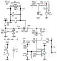
发射功率调节器222用于调节驱动发射器线圈的输入功率,因此发射功率调节器222的配置取决于所使用的电源210和发射器线圈电路的要求。例如,如果电源210提供DC功率,则发射功率调节器222是具有功率整流功能的DC-AC逆变器,而如果电源210供应AC功率,则发射功率调节器222是具有功率调节功能的AC-DC转换器和具有功率整流功能的DC-AC逆变器的组合,从而经由DC传输链路提供AC到AC功率调节。在任一情况下,单个逆变器用于驱动发射器元件阵列。当电源210提供AC功率时,可以将发射功率调节器222配置为直接AC-AC转换器,然而由于不能产生高频输出,因此这种直接转换器通常不适用于IPT应用。如本领域技术人员所熟知的,在非同步配置或同步配置中,功率整流DC-AC逆变器可以被设置为基于开关的整流器,诸如具有开关(诸如基于二极管的开关或半导体开关(诸如晶体管、场效应晶体管(FET)或金属氧化物半导体FET(MOSFET)))的半桥整流器或全桥整流器(FET)。在系统200的特定应用中,功率调节DC-AC转换器可以被设置为与升压转换器、降压转换器、降压-升压转换器或适用于调节功率的其他转换器类型相结合的AC至DC转换器(ADC)。在本文描述的驱动电路的示例中,电源210供应市电额定值的AC,发射器或发射功率调节器具有:ADC,用于将由电源210输入的AC功率转换为DC;降压-升压转换器,用于调节经转换的DC功率;以及半桥整流器,具有成对的FET以整流经调节的功率,从而提供整流的功率到发射线圈212来感应所需的磁通量,然而本领域技术人员理解的是,可以根据本系统的特定应用来等同地使用不同的应用形式的调整器和整流器。The transmit
选择器224可以被设置为与各个发射器线圈212分离且连接的电池或开关阵列,或者被设置为在各个发射电路中分别与线圈212集成的开关。选择器224还可以包括用于以本领域技术人员公知的方式来驱动开关的解复用器和移位寄存器。之后详细讨论驱动电路218的这些组件的操作和效果。The
发射器线圈212的阵列214可以以若干方式来配置。发射器线圈可以被配置为具有与接收器线圈基本相同的尺寸和配置,使得发射器线圈和接收器线圈可以成对耦合。可选地,发射器线圈可以被配置为大于或小于接收器线圈,和/或具有与接收器线圈不同的配置。实际上,不同类型的接收器设备可以具有不同尺寸和配置的接收器线圈,使得这些相对配置的组合可以由本发明的系统和方法来支持。在图2的示例中,发射器线圈212被图示为尺寸小于接收器线圈216但是配置相同(即,通常是椭圆形)。在这种配置中,多个发射器线圈212可以耦接到相应的接收器线圈216,如阴影线的发射器线圈组212a、212b和212c所示。使用多个发射器线圈为单个较大的接收器线圈供电通过有效使用发射器和驱动电路而优化了传输的功率量。如图2所示,基于覆盖在上的接收器线圈的布置(包括相对定向)来选择成组的发射器线圈。The
图2的阵列214是布置发射器线圈212的最简单形式。即,重复模式的发射器线圈被设置在单个层或平面中,其中每个线圈通常与该阵列的所有其他线圈共面。尽管该配置在简化方面有利,但是阵列的其他配置是可能的,包括具有或不具有规则或不规则布置的发射器线圈的层间偏移或重叠的多层或多平面的线圈阵列。这种复杂性提高的阵列提供了其他益处,诸如改善了耦合磁场的均匀性。稍后描述不同阵列形式的具体实施例,然而提供空间自由的多设备IPT充电的目的效果对于这些实施例中的每个是共同的。The
进一步参考图2,发射器202还包括由系统200的用户使用的仪器226。仪器226可以包括诸如按钮的用户控制件和/或诸如发光二极管(LED)的指示器,如图1所示。仪器226可以连接到控制器220或其他控制电路并由其控制,以适用于与系统的操作有关的信息的输入和输出。With further reference to FIG. 2 , the
如前所述,发射器线圈的选择性操作需要识别接收器线圈相对于发射器线圈的定位。本领域中存在用于实现这种目的的各种技术。然而,在示例性实施例中,本发明使用相对简单的技术来首先检测发射器附近(例如,在充电范围内)的接收器或其他物体的存在(“粗略”检测),然后检测接收器线圈相对于发射器线圈的相对位置(“精细”检测)。这在本发明的系统中是有利的,因为一旦检测到存在接收器,仅对用于精细检测的多个发射器线圈进行充分供电,从而使发射器实质上处于低功率的空闲模式或“睡眠”模式。“低”功率的典型值低于约100mW,优选低于约50mW,更优选在约几mW至低于约20mW的范围内。As previously mentioned, selective operation of the transmitter coil requires identifying the positioning of the receiver coil relative to the transmitter coil. Various techniques exist in the art for accomplishing this. However, in an exemplary embodiment, the present invention uses a relatively simple technique to first detect the presence of a receiver or other object in the vicinity of the transmitter (eg, within charging range) ("coarse" detection), and then detect the receiver coil Relative position relative to the transmitter coil ("fine" detection). This is advantageous in the system of the present invention, because once the presence of the receiver is detected, only the multiple transmitter coils for fine detection are sufficiently powered, leaving the transmitter essentially in a low power idle mode or "sleep" "model. Typical values for "low" power are below about 100 mW, preferably below about 50 mW, more preferably in the range of about a few mW to below about 20 mW.
本发明的粗略检测然后进行精细检测的两级接收器检测方法可以提供如下。图3图示了本发明的系统的发射器302的实施例。如图2所示,发射器302以框图形式示出,示出了包括成阵列314的发射元件/线圈312以及驱动电路318的电子器件,驱动电路318包括控制器320、发射功率调节器322和选择器324。另外,发射器302被图示为还具有检测器328和通信模块330。图4以框图形式示出了具有相似组件/元件的发射器402的更详细的示例,发射器402包括成阵列414的发射元件/线圈412、驱动电路418、检测器428和通信模块430,驱动电路418包括控制器420、发射功率调节器422和选择器424。另外,发射功率调节器422被示为具有如前所述的(降压-升压)转换器432和(半桥)整流器434。注意,发射器302和402的组件/元件以类似于发射器202的类似组件/元件的方式来工作,并且在每个图中发射器328和428的检测器和通信模块表示相同的元件。The two-stage receiver detection method of the present invention with coarse detection followed by fine detection can be provided as follows. Figure 3 illustrates an embodiment of a
检测器与控制器结合用于接收器的粗略检测,而控制器结合其他电路可以用于精细检测方法。检测器428被设置为检测传输元件436和相关联的检测电路438。在一个实施例中,检测传输元件432被设置为围绕功率传输元件412的阵列414的线圈。在另一个实施例中,检测传输元件436可以被设置为覆盖阵列414的(至少)部分的线圈或者被设置为多个线圈(或线圈的阵列)。例如,公开号为WO 2014/070026的PCT中公开的检测线圈的配置和操作是传输元件432的可应用的示例性形式,该PCT的公开内容通过引用明确地并入本文中。检测元件436用于确定接收器是否在发射器附近,例如,诸如智能电话的接收器设备是放置在发射器板或充电表面上还是从发射器板或充电表面移除。如前所述,检测器328/428的“线圈”可以是缠绕线圈或印刷电路线圈,或者可以是具有有助于特定应用的形状和尺寸的冲压或印刷线圈。The detector is combined with the controller for coarse detection of the receiver, while the controller combined with other circuits can be used for fine detection methods. The
该检测如下来实现。如图4所示,线圈436在控制器420的控制下由功率调整器440经由检测电路438供电。功率调整器440转换来自电源的输入功率以由检测器428使用。即,类似于发射功率调节器的操作,功率调整器440被配置为向检测线圈436供应经调整的AC信号(电压/电流),以便感应出接收器线圈检测所需的磁通量。例如,功率调整器440可以被设置为与降压转换器、升压转换器或降压-升压转换器组合的ADC。在图4所示的示例性实施例中,功率调整器440是供应有来自DC功率输入442的DC电压的降压-升压转换器。DC功率输入442可以被设置为AC适配器,在该AC适配器处,市电AC功率或DC功率例如经由与PC等的USB连接而被供应给发射器402。本领域技术人员理解,根据功率(发射器)线圈412和检测线圈436的相关的电压/电流需求,功率调整器440可以是驱动电路418的一部分。在图4所示的示例性实施例中,由于相关需求不同,因此用需要第一电压电平的检测器428(和控制器420)以及需要第二电压电平的发射功率调节器422和发射线圈412来提供分开的驱动电子器件。之后描述这些参数的示例性值。在任意一种配置中,由DC功率输入442提供的DC电压可以在经过EMI滤波器块444的电磁干扰(EMI)调节之后被输入到发射器402的电路,EMI滤波器块444包含用于EMI噪声抑制的共模滤波器和差模滤波器。抑制EMI噪声提高了发射器电路的稳定性和响应性,特别是当该系统用于蜂窝通信环境中时。This detection is accomplished as follows. As shown in FIG. 4 ,
在检测器的最简单形式中,所提供的“检测”基本上是对金属检测系统的检测。如本领域技术人员所理解的,检测器的线圈在被供电时引起频率的振荡。在控制器的控制下,通过检测电路来测量该振荡频率(根据在预定时间帧内计数的振荡频率信号的边沿的数目)。当金属物体接近检测线圈并因此接近发射器时,由于金属吸收由检测线圈发射的磁通量的能量,使得振荡在频率上改变,从而改变在该时间段中计数的边沿的数量。变化的量根据金属物体吸收的能量的量而改变。因此,通过对该振荡频率变化设置极限或阈值,可以检测“金属物体”。可以在单个时间段内或在一系列时间段内测量(即,检测)该变化。用于检测和计数边沿的合适方法是众所周知的,因此这里不再详细讨论。In the simplest form of the detector, the "detection" provided is basically the detection of a metal detection system. As understood by those skilled in the art, the coil of the detector causes oscillations in frequency when powered. Under the control of the controller, the oscillation frequency is measured by a detection circuit (according to the number of edges of the oscillation frequency signal counted within a predetermined time frame). When a metal object approaches the detection coil and thus the transmitter, the oscillations change in frequency due to the metal absorbing the energy of the magnetic flux emitted by the detection coil, thereby changing the number of edges counted in that time period. The amount of change varies according to the amount of energy absorbed by the metal object. Therefore, by setting a limit or threshold for this oscillation frequency change, a "metal object" can be detected. The change can be measured (ie, detected) over a single time period or over a series of time periods. Suitable methods for detecting and counting edges are well known and will not be discussed in detail here.
检测线圈振荡的频率通过适当选择检测电路的组件(其可以是可变组件)以及检测线圈的尺寸和拓扑来选择,以便处于不同于或偏离发射线圈被驱动的频率的频率范围内。以这种方式,由检测器提供的粗略检测不会干扰发射器对接收器供电的操作。在本发明的示例中,检测频率在MHz范围内,例如,大约1MHz,而功率传输在kHz范围内,例如,大约100kHz(稍后讨论更具体的值范围)。在该频率范围内,用于检测的预定(第一)时间段在毫秒(ms)范围内,例如,大约40ms。因此,通过检测线圈的恒定操作和以规则时间间隔对振荡频率采样以确定是否发生改变来执行对进入发射器附近的物体的“搜索”。不仅在物体被放置在发射器“板”上时,而且还在物体朝向、沿着或远离发射器移动时,都认为在检测“脉冲”之间大约500ms的(第二)时间段适用于检测物体,其中“接近”被认为是在小于100毫米(mm)的范围内,例如,大约3mm至大约30mm,这是系统的充电范围。然而,根据所需检测的“粗糙度”,第一时间段和第二时间段可以选择为更小或更大。The frequency at which the detection coil oscillates is selected by appropriate selection of the components of the detection circuit, which may be variable components, and the size and topology of the detection coil, so as to be in a frequency range different from or offset from the frequency at which the transmit coil is driven. In this way, the coarse detection provided by the detector does not interfere with the operation of the transmitter to power the receiver. In an example of the present invention, the detection frequency is in the MHz range, eg, about 1 MHz, and the power transfer is in the kHz range, eg, about 100 kHz (more specific value ranges are discussed later). In this frequency range, the predetermined (first) time period for detection is in the millisecond (ms) range, eg, about 40 ms. Thus, a "search" for objects entering the vicinity of the transmitter is performed by detecting constant operation of the coil and sampling the oscillation frequency at regular time intervals to determine if a change has occurred. A (second) period of about 500ms between detection "pulses" is considered suitable for detection not only when the object is placed on the transmitter "plate", but also when the object is moving towards, along or away from the transmitter Objects, where "proximity" is considered to be in the range of less than 100 millimeters (mm), eg, about 3 mm to about 30 mm, which is the charging range of the system. However, the first time period and the second time period may be chosen to be smaller or larger, depending on the desired "roughness" of detection.
虽然检测线圈的操作不会显著干扰发射器线圈的操作,但发射器线圈的操作确实干扰检测线圈的操作,这是因为在充电发生时,检测线圈的振荡频率改变。这部分地归因于在整个充电期间接收器设备在发射器的充电表面上的持续存在,以及部分地归因于供电的发射器线圈的感应磁场对(较大)检测器线圈的感应磁场的影响。然而,这种影响被简单地解释为,因为振荡频率的突然变化被测量到,使得充电顺序的效果仅仅移动了频率三角测量(frequency delta measurement)的基线,如稍后更详细讨论的。While the operation of the detection coil does not significantly interfere with the operation of the transmitter coil, the operation of the transmitter coil does interfere with the operation of the detection coil because the oscillation frequency of the detection coil changes as charging occurs. This is due in part to the persistent presence of the receiver device on the charging surface of the transmitter throughout the charging period, and in part to the difference between the induced magnetic field of the powered transmitter coil versus the (larger) detector coil's induced magnetic field influences. However, this effect is simply explained as the effect of the charging sequence simply shifts the baseline of the frequency delta measurement because a sudden change in the oscillation frequency is measured, as discussed in more detail later.
用于检测的测量的频率变化的阈值的设置可以根据系统的应用通过实验来确定,或者可以通过校准来设置,或者可以由于多个接收器设备在发射器表面上的放置来动态地确定并用作频率值的“滚动”平均(‘rolling’average)。在本文描述的系统的示例性实施例中,约5%至约10%的边沿计数的顺序读数之间的变化被认为与环境有关(例如,“背景噪声”),因此被忽略(参见图5(A))。当与其中部署了IPT系统的典型环境相比,包含相对大量金属的密集物体的实际消费设备(诸如智能电话)被放置在发射器表面上时,导致振荡频率的相当大的变化,例如,对于典型的智能手机,在两个顺序读数之间可以观察到几乎两倍的频率,并且比下一读数进一步增加约150%至约200%(参见图5(B))。这样的“事件”用于“触发”精细检测,精细检测将判断检测到的“物体”是接收器还是只是放置在发射器上并因此不应被供电的一些其他金属物体,即,所谓的“异物”或“寄生负载”,如稍后更详细讨论的。The setting of the threshold value of the measured frequency change for detection may be determined experimentally depending on the application of the system, or may be set by calibration, or may be determined dynamically due to the placement of multiple receiver devices on the transmitter surface and used as 'rolling' average of frequency values. In an exemplary embodiment of the system described herein, the variation between sequential readings of about 5% to about 10% of edge counts is considered to be context dependent (eg, "background noise") and is therefore ignored (see Figure 5 (A)). When compared to typical environments in which IPT systems are deployed, actual consumer devices, such as smartphones, containing dense objects containing relatively large amounts of metal, are placed on the surface of the transmitter, resulting in considerable changes in the frequency of oscillation, e.g. for For a typical smartphone, almost twice the frequency can be observed between two sequential readings and a further increase of about 150% to about 200% over the next reading (see Figure 5(B)). Such "events" are used to "trigger" fine detection, which will tell whether the detected "object" is the receiver or some other metal object that is just placed on the transmitter and therefore should not be powered, i.e., the so-called "object" foreign objects" or "parasitic loads," as discussed in more detail later.
虽然图5(A)和图5(B)中所示的结果图示了对于相对敏感“事件”检测来说可以设置大于约10%的频率变化阈值,或者说对于相对粗略事件检测来说可以设置约50%或更大的频率变化阈值,但是在设置阈值时应考虑其他因素,使得不产生其中使用更耗时和耗能的精细检测方法的“误报(false positives)”。While the results shown in Figures 5(A) and 5(B) illustrate that a frequency change threshold greater than about 10% can be set for relatively sensitive "event" detection, or for relatively coarse event detection A frequency change threshold of about 50% or greater is set, but other factors should be considered when setting the threshold so that "false positives" are not produced where more time and energy consuming refined detection methods are used.
例如,在系统附近使用的环境中的金属的量可能影响背景变化。虽然当系统的最终使用的位置和环境是未知的且不受约束时,难以以预定方式解释这些因素,但是可以通过检测器线圈的适当设计来减小影响的水平。例如,如本领域技术人员所理解的,可以使用定向线圈拓扑、屏蔽、磁场成形等。For example, the amount of metal in the environment used in the vicinity of the system may affect the background variation. Although it is difficult to account for these factors in a predetermined manner when the location and environment of the final use of the system are unknown and unconstrained, the level of influence can be reduced by proper design of the detector coils. For example, directional coil topology, shielding, magnetic field shaping, etc. may be used, as understood by those skilled in the art.
此外,振荡频率可以因功率发射器线圈的供能而改变。如前所述,在本示例中,在被供电时发射器线圈412以约100kHz至约120kHz的频率振荡,如本领域技术人员公知的。发射线圈的这种振荡影响检测线圈的振荡,从而导致检测读数的约为10%或更大的变化(见图5(C))。因此,在设置粗略检测阈值时,需要理解和解释功率传输或充电线圈的供电的影响。Furthermore, the oscillation frequency can be changed by the energization of the power transmitter coil. As previously mentioned, in this example, the
必须考虑的另一个因素是由耦合到发射器的接收器汲取的充电电流对检测器电路的振荡频率的影响。汲取电流的这种变化是由于消费电子接收器设备的电池或其他能量储存设备的“电荷”水平随时间的变化以及在发射器侧实施的用来负责功率传输效率方面的变化的功率流控制(稍后详细讨论)导致的。具体地,这是经过较长的时间(即,对智能手机电池充电所需的时间长度,例如,约一个小时左右)观察到的,在该时间期间功率调整器440的降压转换器电压中的负载阶跃反映了接收器所需的功率的量,并且这个变化的量反过来反映了作为振荡频率的波动变化的检测读数(参见图5(D))。这种随时间的变化可以用根据降压转换器电压负载阶跃来动态地设置振荡频率的“基线”的检测算法来解释,这对控制器420是已知的。当然,将理解,一次被供电/充电的设备的数量以及被供电/充电的设备的类型以及这些设备的相对“电荷水平”也影响检测测量值。Another factor that must be considered is the effect of the charging current drawn by the receiver coupled to the transmitter on the oscillation frequency of the detector circuit. This variation in current drawn is due to changes in the "charge" level of the battery or other energy storage device of the consumer electronics receiver device over time and the power flow control implemented on the transmitter side to account for changes in power transfer efficiency ( discussed in detail later). Specifically, this is observed over an extended period of time (ie, the length of time required to charge a smartphone battery, eg, about an hour or so), during which time the buck converter voltage of the
通过将对检测线圈磁性的这些已知的影响相结合,可以为粗略或初始(初级)检测方案提供鲁棒且有效的检测方案。例如,在操作或预设期间,可以基于多设备充电系统的“模式”或使用情况(例如,没有设备被供电/充电、特定类型的一个设备被供电/充电、另一特定类型的一个设备被供电/充电、相同或不同类型的两个设备被供电/充电等)来动态地确定一组阈值。此外,被检测和计数的边沿可以是正向边沿或负向边沿,然而,针对更具体的分类,也可以使用对于正向边沿和负向边沿来讲的不同的阈值的隔离。此外,通过检测发射器处的条件的变化而不是测量静态值,仅需要进行对物体的检测一次,使得如果一旦执行“精细”检测或第二(二次)检测,而检测到的物体结果不是接收器设备,则检测到的物体不会触发再次执行二次检测的需要。By combining these known effects on the detection coil magnetism, a robust and efficient detection scheme can be provided for a coarse or initial (primary) detection scheme. For example, during operation or presets, the multi-device charging system may be based on "modes" or usage conditions (eg, no device is powered/charged, one device of a particular type is powered/charged, one device of another particular type is powered/charged, power/charge, two devices of the same or different types are powered/charged, etc.) to dynamically determine a set of thresholds. Furthermore, the detected and counted edges can be positive or negative going edges, however, for a more specific classification, isolation of different thresholds for positive and negative going edges can also be used. Furthermore, by detecting changes in conditions at the transmitter rather than measuring static values, the detection of the object only needs to be done once, so that if once a "fine" detection or a second (secondary) detection is performed, the detected object turns out not to be receiver device, the detected object does not trigger the need to perform a secondary detection again.
在另一示例中,或者除了这种软件解释之外,可替代地,IPT场对检测场的影响可以被解释为硬件而不是如上所述的软件。图20A图示了在公开号为WO 2014/070026的PCT中所公开的(自振荡)周边线圈的等效电路。利用该电路,当金属放置在“环形”线圈L1内部时,该线圈的电感改变,导致使用所示比较器电路测量的振荡频率(由电感器L1和电容器C1的谐振电路提供)的变化。然而,如上所讨论的,功率发射线圈的操作可以使环形线圈与IPT场耦合,从而恶化检测信号。为了减小IPT场对检测线圈的不利影响(即,噪声),可以在检测器电路中设置合适的滤波器,如图20B所示。在该示例中,电感器L3和电容器C3的LC滤波器与检测器线圈L1并联添加,电感器L2和电容器C2的LC滤波器也设置在比较器电路中。以这种方式,减小了(在比较器电路中)电感器L1和L2与IPT场的耦合。In another example, or in addition to this software interpretation, the effect of the IPT field on the detection field may alternatively be interpreted as hardware rather than software as described above. Figure 20A illustrates the equivalent circuit of the (self-oscillating) peripheral coil disclosed in PCT Publication No. WO 2014/070026. With this circuit, when metal is placed inside the "ring" coil L1, the inductance of this coil changes, resulting in a change in the oscillation frequency (provided by the resonant circuit of inductor L1 and capacitor C1) measured using the comparator circuit shown. However, as discussed above, operation of the power transmit coil can couple the loop coil to the IPT field, thereby degrading the detection signal. To reduce the adverse effects (ie, noise) of the IPT field on the detection coil, suitable filters can be placed in the detector circuit, as shown in Figure 20B. In this example, the LC filter of inductor L3 and capacitor C3 is added in parallel with detector coil L1, and the LC filter of inductor L2 and capacitor C2 is also provided in the comparator circuit. In this way, the coupling of the inductors L1 and L2 to the IPT field (in the comparator circuit) is reduced.
从上述可以理解,物体检测方法不仅可以用于检测包括接收器设备的物体的存在,还可以用于使用相同的阈值方案来检测这些物体的不存在,即,当接收器设备从发射器的充电表面移除,或者相对于充电表面移动时。以这种方式,可以以简单的方式精确地控制发射器的充电模式,从而提供低功率和安全操作。As can be understood from the above, the object detection method can be used not only to detect the presence of objects including the receiver device, but also to detect the absence of these objects using the same thresholding scheme, i.e. when the receiver device is charged from the transmitter When the surface is removed, or moved relative to the charging surface. In this way, the charging mode of the transmitter can be precisely controlled in a simple manner, providing low power and safe operation.
在本发明的系统的发射器的操作中,如下来提供高效且有效的物体检测功能。在上述方案下,在对发射器上电时(即,当从电源向发射器供电时),不对发射器线圈供电,而对检测器线圈供电,以检测包括接收器设备的物体是否在发射器的充电范围内。在对发射器供电时,持续执行物体检测,而在发射器断电时,停止物体检测。In operation of the transmitter of the system of the present invention, an efficient and effective object detection function is provided as follows. Under the above scheme, when the transmitter is powered up (ie, when power is supplied to the transmitter from a power source), the transmitter coil is not powered, but the detector coil is powered to detect whether an object including the receiver device is in the transmitter within the charging range. When power is supplied to the transmitter, object detection is continuously performed, and when the transmitter is powered off, object detection is stopped.
一旦检测到邻近的物体,系统就结合控制器来执行接收器的检测。这种“精细”检测相当于对发射器“板”或充电表面的扫描,以确定所检测物体的实际位置以及所检测物体是否是接收器设备。该扫描通过选择性地激活阵列的发射器线圈以确定物体是否位于那些发射器线圈的离散的已知的位置中来实现。检测到的物体可以是接收器设备或包含如前讨论的金属的其他物体。通过金属与由发射器线圈发射的能量的相互作用来促进检测。以这样的方式执行发射器线圈的激活,使得所发射的能量可以引起发射器线圈与邻近接收器线圈的耦合,而不需要对与耦合的接收器线圈相关联的接收器电路/负载实际供电/充电。具体地,执行扫描,从而通过发射器线圈和物体的磁相互作用来确定使用物体检测器所检测到的任何潜在物体的位置。可以根据发射器线圈阵列的配置以多种方式执行扫描和检测。例如,公开号为WO 2013/165261的PCT和公开号为WO 2014/070026的PCT中公开的浪涌电流测量和检测方法的原理可以用作本发明的“精细”检测方法的测试或步骤的基础,它们两的内容通过引用被明确地并入本文,以及公开号为WO 2013/165261的PCT中公开的扫描检测方法可以用作本发明的“精细”检测方法的测试或步骤的基础。或者,可以使用定位接收器的其他方法,包括稍后讨论的示例性方法。Once an adjacent object is detected, the system, in conjunction with the controller, performs the detection of the receiver. This "fine" detection is equivalent to scanning the transmitter "plate" or charging surface to determine the actual location of the detected object and whether the detected object is a receiver device. The scanning is accomplished by selectively activating the transmitter coils of the array to determine whether objects are located in discrete known locations of those transmitter coils. The detected object may be a receiver device or other object containing metal as previously discussed. Detection is facilitated by the interaction of the metal with the energy emitted by the transmitter coil. Activation of the transmitter coil is performed in such a way that the transmitted energy can cause the coupling of the transmitter coil to an adjacent receiver coil without actually powering the receiver circuit/load associated with the coupled receiver coil/ Charge. Specifically, a scan is performed to determine the location of any potential objects detected using the object detector through the magnetic interaction of the transmitter coil and the object. Scanning and detection can be performed in a variety of ways depending on the configuration of the transmitter coil array. For example, the principles of the surge current measurement and detection methods disclosed in PCT Publication No. WO 2013/165261 and PCT Publication No. WO 2014/070026 can be used as the basis for the tests or steps of the "fine" detection method of the present invention , the contents of both of which are expressly incorporated herein by reference, and the scanning detection method disclosed in PCT Publication No. WO 2013/165261 can be used as the basis for the tests or steps of the "fine" detection method of the present invention. Alternatively, other methods of locating the receiver may be used, including the exemplary methods discussed later.
如在公开号为WO 2013/165261的PCT和公开号为WO 2014/070026的PCT中所公开的,如果接收器电子器件的特性已知,则浪涌和频率扫描检测方法可以用于“识别”接收器设备以及定位该设备。说到这里,稍后讨论定位和识别接收器的替代方法。该识别有助于判断检测到的物体是否是兼容的以通过发射器供电/充电的接收器设备。关于该功能,本发明的系统与用于对消费电子设备进行无线功率充电的常规系统的区别如下。As disclosed in PCT Publication No. WO 2013/165261 and PCT Publication No. WO 2014/070026, surge and frequency sweep detection methods can be used to "identify" if the characteristics of the receiver electronics are known receiver device and locating that device. Having said that, alternative methods of locating and identifying receivers are discussed later. This identification helps to determine if the detected object is a compatible receiver device to be powered/charged by the transmitter. Regarding this function, the system of the present invention differs from conventional systems for wireless power charging of consumer electronic devices as follows.
如前所述,发射器可以使用相同类型或不同类型的两个或更多个接收器设备并对它们供电。这些接收器类型不仅包括诸如智能手机、平板电脑等的设备类型和诸如3瓦、10瓦等的功率额定类型,还包括符合行业标准定义的不同规范的接收器类型。支持这些不同的规范是重要的,以便当行业标准的规范通过该标准的演变而改变时允许向后兼容。即,符合规范的早期版本的设备可能不(完全)符合该规范的后期版本。因此,支持使用为较新版本设备设计的发射器来对那些早期版本设备的供电/充电意味着不会严重损害该标准的早期设备,至少直到它们能够为了较新版本而逐渐淘汰早期版本设备。虽然这是明智的,但是不同代的基于标准的规范在电路设计和操作方面可能不是互补或兼容的。目前,用于消费设备的无线功率行业具有由不同的标准制定组织(SSO)制定的若干规范。由于所使用的无线功率传输的底层技术大不相同,因此这些冲突的规范甚至更难以用单个系统来支持。As previously mentioned, a transmitter may use and power two or more receiver devices of the same type or of different types. These receiver types include not only device types such as smartphones, tablets, etc. and power rating types such as 3 watts, 10 watts, etc., but also receiver types that conform to different specifications defined by industry standards. It is important to support these different specifications in order to allow backward compatibility as the specifications of the industry standard change through the evolution of the standard. That is, a device that conforms to an earlier version of the specification may not (fully) conform to a later version of the specification. Thus, supporting the use of transmitters designed for newer version devices to power/charge those earlier version devices means that earlier devices of the standard will not be severely compromised, at least until they can phase out earlier version devices for newer versions. While this is sensible, different generations of standards-based specifications may not be complementary or compatible in circuit design and operation. Currently, the wireless power industry for consumer devices has several specifications developed by different standards-setting organizations (SSOs). These conflicting specifications are even more difficult to support with a single system due to the vastly different underlying technologies used for wireless power transfer.
在这种情况下,本发明的系统提供了一种机制,该机制用于识别对于发射器来讲而存在的接收器设备的“类型”或至少接收器设备的特性,以及用于支持通过这种识别来对多种“类型”的接收器设备进行充电。本发明的系统还提供了一种机制,通过该机制接收器设备向发射器识别其自身,而无论该发射器是本系统的一部分还是工业标准规范的不同版本的一部分。In this case, the system of the present invention provides a mechanism for identifying the "type" of receiver equipment present to the transmitter, or at least the characteristics of the receiver equipment, and for supporting This identification is used to charge multiple "types" of receiver devices. The system of the present invention also provides a mechanism by which a receiver device identifies itself to a transmitter, whether the transmitter is part of the system or part of a different version of an industry standard specification.
作为本发明的系统的多设备类型供电/充电能力的示例应用,现在描述图3的通信模块330的操作。在该示例性实施例中,通信模块符合在第一版本行业标准规范中阐述的通信需求,使得可以用符合该第一版本规范的接收器设备以及符合第二版本行业标准规范的接收器设备来进行识别、通信和供电/充电,其中,第二版本晚于第一版本。为了执行这种多版本接收器支持,发射器302需要在接收器类型之间进行区分,使得可以选择适当版本的无线功率传输模式。As an example application of the multi-device type powering/charging capability of the system of the present invention, the operation of the
对于从发射器到接收器的功率传输,早期版本的规范具有以下四个阶段:For power transfer from transmitter to receiver, earlier versions of the specification had the following four phases:
·选择·choose
发射器监视发射器(接口)表面上物体的放置和移除。如果发射器检测到物体,则系统进入Ping阶段。The transmitter monitors the placement and removal of objects on the transmitter (interface) surface. If the transmitter detects an object, the system enters the Ping phase.
·Ping·Ping
发射器执行数字ping,并侦听响应。如果发射器接收到响应,则系统进入识别&配置阶段。The transmitter performs a digital ping, and listens for responses. If the transmitter receives a response, the system enters the identification & configuration phase.
·识别&配置· Identify & configure
发射器识别接收器并获取配置信息,诸如接收器意图在其输出(负载)处提供的最大功率量。一旦识别并配置了接收器,则系统进入功率传输阶段。The transmitter identifies the receiver and obtains configuration information, such as the maximum amount of power the receiver is intended to provide at its output (load). Once the receiver is identified and configured, the system enters the power transfer phase.
·功率传输· Power transfer
发射器向接收器提供功率,响应于其从接收器接收到的控制数据来调整其线圈电流。The transmitter provides power to the receiver, adjusting its coil current in response to control data it receives from the receiver.
在早期版本规范的这种方案中,从任何其他阶段到选择阶段的转换涉及发射器去除至接收器的功率信号。在本发明中,这些阶段执行如下。选择阶段涉及如前所述的由本发明的系统执行的物体检测。按照现在将描述的本发明的方式来执行Ping和识别&配置阶段。根据接收器的版本被识别为处于早期版本模式(其中发射器调整如上所述的被传输的功率量)或者处于较新版本模式(其中接收器调整被传输到接收器侧负载的接收功率的量,如稍后将描述的)来执行功率传输阶段。在以下描述中,早期版本的规范被称为版本A,而较新版本的规范被称为版本B。应当理解,可以以类似方式支持不同版本或更多版本的标准规范。In this scheme of earlier versions of the specification, the transition from any other stage to the selection stage involves the transmitter removing the power signal to the receiver. In the present invention, these stages are performed as follows. The selection phase involves object detection performed by the system of the present invention as previously described. The Ping and Identify & Configure phases are performed in the manner of the present invention as will now be described. Depending on the version of the receiver is identified as being in an earlier version mode (where the transmitter adjusts the amount of power delivered as described above) or in a newer version mode (where the receiver adjusts the amount of received power delivered to the receiver side load) , as will be described later) to perform the power transfer phase. In the following description, earlier versions of the specification are referred to as version A, and newer versions of the specification are referred to as version B. It should be understood that different or more versions of the standard specification may be supported in a similar manner.
首先,描述本发明的Ping阶段。在本实施例中,本发明的版本B发射器(例如,发射器302)首先通过选择性地对发射器线圈312供电来进行接收器位置扫描,进而首先判断存在版本A接收器还是版本B接收器,如果不是,则位置扫描结束。这仅仅是示例,并且各种版本可以随后被定位(例如,按顺序),而不是在同一扫描内。First, the Ping phase of the present invention is described. In this embodiment, a Revision B transmitter of the present invention (eg, transmitter 302 ) first performs a receiver location scan by selectively powering the
为了检测接收器设备在发射器表面上的位置并且识别该接收器设备,可以使用发射器和接收器之间的通信协议。该通信协议可以根据任一一种版本规范,使得可以以时间有效的方式检测版本A和版本B设备。时间效率是预期的,使得系统的用户体验不会由于必须等待接收器设备在由发射器供电/充电之前被检测到而受到严重影响。图6示出了版本A通信协议的示例性通信或数据“包”的组件。该包包括由1和0比特位组成的比特流。如图6(A)和6(B)所示,在时钟信号tCLK的单个周期中,0比特位被编码为单个转换,而在单个时钟周期中,1比特位被编码为两个转换,其中时钟周期是例如约2kHz。由于比特位被编码为一个或两个转换,所以信号的初始状态是什么无关紧要,只有在时钟周期的期间内发生多少次转换是重要的。包的每个字节以11位异步串行格式来编码,如图6(C)所示,一个启动位、一个奇校验位和一个停止位。图6(D)示出具有四个部(部分或字段)的包:11至25比特位的前导部分(preamble portion),所有比特位都被设置为1(即,在前导部分中不对字节编码);单个字节的报头部分(header portion),指示消息部分字节的包类型和数量;一个或更多个字节的消息部分;以及单个字节的校验和部分(checksum portion),被计算为报头部分字节与每个消息部分字节进行XOR。In order to detect the position of the receiver device on the surface of the transmitter and to identify the receiver device, a communication protocol between the transmitter and the receiver can be used. The communication protocol can be according to either version specification, so that version A and version B devices can be detected in a time efficient manner. Time efficiency is expected so that the user experience of the system is not severely affected by having to wait for the receiver device to be detected before being powered/charged by the transmitter. FIG. 6 illustrates components of an exemplary communication or data "packet" of the Version A communication protocol. The packet includes a bit stream consisting of 1 and 0 bits. As shown in Figures 6(A) and 6(B), in a single cycle of the clock signal tCLK , a 0-bit bit is encoded as a single transition, and in a single clock cycle, a 1-bit bit is encoded as two transitions, where the clock period is, for example, about 2 kHz. Since bits are encoded as one or two transitions, it does not matter what the initial state of the signal is, only how many transitions occur during the duration of the clock cycle. Each byte of the packet is encoded in an 11-bit asynchronous serial format, as shown in Figure 6(C), with a start bit, an odd parity bit, and a stop bit. Figure 6(D) shows a packet with four parts (parts or fields): a preamble portion of 11 to 25 bits, with all bits set to 1 (ie, no bytes in the preamble portion). encoding); a single-byte header portion, indicating the packet type and number of bytes of the message part; a message part of one or more bytes; and a single-byte checksum portion, Calculated as an XOR of the header part bytes with each message part byte.
在操作中,通过发射器302从阵列314的每个发射器线圈312在预定时间段(例如,从大约100ms到大约300ms)顺序地发送“ping”。“ping”是离散的非充电能量信号,其能够将发送ping的发射器线圈与附近的接收器线圈临时耦合。通过控制发射功率调节器322经由使用选择器324选中的发射器线圈312在特定时间段上输出适当的功率信号来实现ping。由临时ping信号传送的功率使得耦合的接收器设备将耦合通信包“发送”到发射器302,发射器302的通信模块330包括用于解码和处理接收到的包的解码和处理电路。用于执行这些功能的电路可以在控制器320的控制下被设置在发射器302的通信模块330中,或者可以被设置为控制器320本身的一部分。在后面描述接收器对要在包中传送的信息进行编码的方式以及这些包被“发送”的方式。In operation, "pings" are sequentially sent by the
图7是示出用于解码所接收的包的解码器702和用于处理如在控制器320或通信模块330中实现的解码包的状态机704的框图。还示出了用于测量所接收的通信包内的时间段的定时器706。解码器702被配置为:根据版本A通信协议,仅当接收到至少四个前导比特位,消息中没有奇偶校验错误,并且校验和匹配时,才考虑接收包的消息有效;然而其他有效性标准是可能的。解码器702将解码的消息传递到状态机704,以及指示何时接收到了具有错误的消息。状态机704处理解码的包。7 is a block diagram illustrating a
如上所述,接收ping信号的能量的接收器设备通过向发射器发送耦合通信包来响应。该耦合(第一)通信包可以是信号强度包的形式。信号强度包传送包的消息部分中的信号强度值,其指示发送ping的发射器线圈与耦合的接收器线圈之间的耦合程度。状态机704处理该接收到的信号强度包,由此发射器302能够将接收器设备定位在进行发射的发射线圈的本地位置,因为如本领域技术人员所理解的,在IPT领域中是发射线圈来接收信号强度包首先作为反射信号。As described above, the receiver device receiving the energy of the ping signal responds by sending a coupled communication packet to the transmitter. The coupled (first) communication packet may be in the form of a signal strength packet. The Signal Strength Packet conveys a signal strength value in the message portion of the packet that indicates the degree of coupling between the transmitter coil sending the ping and the coupled receiver coil. The
为了进一步定位接收器设备,也可以从信号强度包推导出用于对接收器设备供电/充电的一个或更多个发射器线圈。即,如下面所讨论的,并且在下面更详细地讨论的,接收器被配置为测量发射器线圈中的特定发射器线圈与接收器设备的接收器线圈之间的耦合水平,以及被配置为通过传送信号强度来向发射器指示该耦合水平。因此,发射器可以判断哪个发射器线圈或发射器线圈的组合给出最佳耦合。例如,如果要使用两个或更多个发射器线圈的组合来最大化功率传输,同时最大化功率效率,则控制器320可以判断哪个发射器线圈312提供最大信号强度测量,以及邻近那个“最佳”的发射器线圈312的哪些发射器线圈312提供次“最佳”信号强度,从而使用选择器324来选择“最佳”两个发射器线圈312进行功率传输。或者,可以使用相同或不同参数的其他测量,诸如之前讨论的电流涌流方法。To further locate the receiver device, one or more transmitter coils for powering/charging the receiver device can also be derived from the signal strength packets. That is, as discussed below, and in more detail below, the receiver is configured to measure the level of coupling between a particular one of the transmitter coils and the receiver coil of the receiver device, and is configured to This coupling level is indicated to the transmitter by transmitting the signal strength. Thus, the transmitter can determine which transmitter coil or combination of transmitter coils gives the best coupling. For example, if a combination of two or more transmitter coils is to be used to maximize power transfer while maximizing power efficiency, the
尽管已经描述了两级接收器检测方法,其中首先使用低功率粗略检测方法来检测物体,然后使用精细检测扫描方法来相对于发射器线圈定位物体,但是单级检测方法也在本发明的范围内。例如,如果对于特定应用,检测新出现的接收器设备或先前出现的接收器设备的移动时的功率效率被认为具有较低的重要性,则在特定情况下或者通过从系统完全省略物体检测电路和相关软件来省略粗略检测。实际上,发射器和接收器的电路可以被配置为使得在发射器板扫描期间优化功率效率,或者检测/定位的速度上的任何相应增加可以被评估为高于低功率“空闲”模式或待机模式的需要。Although a two-stage receiver detection method has been described in which an object is first detected using a low-power coarse detection method, and then a fine-detection scanning method is used to locate the object relative to the transmitter coil, a single-stage detection method is also within the scope of the present invention . For example, if, for a particular application, power efficiency in detecting the movement of a newly emerging receiver device or a previously occurring receiver device is considered to be of lesser importance, then in that particular case or by omitting the object detection circuitry entirely from the system and related software to omit rough detection. In practice, the circuitry of the transmitter and receiver can be configured such that power efficiency is optimized during the scan of the transmitter board, or any corresponding increase in the speed of detection/location can be evaluated over a low power "idle" mode or standby mode needs.
一旦定位接收器设备,则系统进入识别&配置阶段。在该阶段,发射器识别接收器并获得配置信息,诸如接收器意在其输出(负载)处提供的最大功率量。例如,这是通过所定位的接收器设备在接收到ping信号的能量时也向发射器发送识别通信包来实现的。该识别(第二)通信包在该包的消息部分中传送接收器设备的识别。例如,根据版本A通信协议,所述消息包含:版本代码、制造商代码和基本设备标识符,其中版本代码指定接收器是版本A和/或版本B兼容的,制造商代码识别接收器的制造商,以及基本设备标识符是可以随机产生以确保充分唯一性的接收器设备标识(例如,设备ID或ID代码)。状态机704处理该接收到的标识包,从而发射器302能够识别已经被定位的接收器设备。在版本A通信协议中,标识包伴随有配置(第三)通信包,其中该包的消息部分指示接收器设备已经被配置来接收的最大功率。状态机704处理该接收的配置包,从而发射器302能够相应地配置功率传输模式的参数。对于版本B接收器,配置包可以包含附加的配置信息,诸如为接收器供电所需的发射器线圈的最大/最小数量。Once the receiver device is located, the system enters the identification & configuration phase. At this stage, the transmitter identifies the receiver and obtains configuration information, such as the maximum amount of power the receiver is intended to provide at its output (load). This is accomplished, for example, by the located receiver device also sending an identifying communication packet to the transmitter when it receives the energy of the ping signal. The identification (second) communication packet conveys the identification of the receiver device in the message portion of the packet. For example, according to the version A communication protocol, the message contains: a version code, a manufacturer code, and a basic device identifier, where the version code specifies that the receiver is version A and/or version B compliant, and the manufacturer code identifies the receiver's manufacture quotient, and the base device identifier is a receiver device identification (eg, a device ID or ID code) that can be randomly generated to ensure sufficient uniqueness. The
作为响应于来自发射器的ping而顺序地提供耦合、识别和配置包的上述协议的替代,系统可以被配置为在更多或更少的数据包中发送类似的信息。图6(E)图示了一种可选的包结构,其中ID部分或字段被设置在报头部分与消息部分之间。这允许与随后通信期间可能有用的所有数据包一起发送设备的身份(诸如基本设备标识符),如稍后所述。此外,如果版本和制造商代码可以从ID代码内推出来,则这可以避免对(产生和)发送单独的标识数据包的需求,这可以有助于加速位置和识别扫描。此外,ID代码还可以用于最初定义所识别的接收器设备的配置要求,使得也可以省略配置数据包,从而进一步加快本系统的“精细”检测方法的处理时间。As an alternative to the above-described protocol that sequentially provides coupling, identification, and configuration packets in response to pings from the transmitter, the system may be configured to send similar information in more or fewer packets. FIG. 6(E) illustrates an alternative packet structure in which an ID part or field is provided between the header part and the message part. This allows the identity of the device (such as the basic device identifier) to be sent along with all data packets that may be useful during subsequent communications, as described later. Furthermore, if the version and manufacturer codes can be deduced from within the ID code, this can avoid the need to (generate and) transmit separate identification packets, which can help speed up location and identification scans. In addition, the ID code can also be used to initially define the configuration requirements of the identified receiver device, so that configuration packets can also be omitted, thereby further speeding up the processing time of the system's "fine" detection method.
为了描述功率传输阶段,首先有益的是详细描述适用于本发明的与可应用的示例性发射器相关的接收器设备的示例。In order to describe the power transfer phase, it is first beneficial to describe in detail an example of a receiver device suitable for use with the present invention in relation to an applicable exemplary transmitter.
图8图示了本发明的系统的接收器804的实施例。以框图形式图示了接收器804,该框图示出了包括接收功率管理电路806和接收器电路808的电子器件,接收器电路808包括控制器810、接收功率调节器812和通信模块814以及负载816。图9以框图形式示出了具有类似组件/元件的接收器904的更详细示例,接收器904包括接收功率管理电路906和接收器电路908,接收器电路908包括控制器910、接收功率调节器912和通信模块914、以及负载916和电流感测电路917。此外,接收功率调节器912被图示为具有功率整流器918和电压调整器920,并且针对上下文示出了来自图3的线圈阵列314的发送的能量。注意,接收器804和904的类似组件/元件以彼此类似的方式工作。Figure 8 illustrates an embodiment of a
控制器810/910可以被设置为诸如微控制器或微处理器的可编程集成电路形式的数字控制器,或者被设置为分立电路组件形式的模拟控制器。在本文描述的接收功率管理电路和接收器电路的示例中,提供微控制器不仅用于对接收器侧负载进行功率流控制,还作为接收器的主处理电路,然而本领域技术人员理解,根据本系统的特定应用,可以等同地使用不同适用形式的控制器。The
如本领域技术人员所熟知的,在非同步配置或同步配置中,功率整流器918可以被设置为基于开关的整流器,诸如具有开关(诸如基于二极管的开关,或诸如半导体开关(诸如晶体管、FET或MOSFET))的半桥整流器或全桥整流器。电压调整器920可以被设置为低压降调整器(LDO)或适合于调整系统的特定应用中的电压的其他电路。由于接收器线圈接收的功率是AC信号,在本文描述的接收器电路908的示例中,接收功率调节器具有功率整流器918和电压调整器920,功率整流器918被配置为将AC电压转换成DC电压的全桥整流器,电压调整器920被配置为用于将经整流的DC电压(即,图9中所示的中间电压)调整到适于传送到负载916的电压的LDO,然而本领域技术人员理解,根据本系统的特定应用,可以等同地使用不同适用形式的整流器和调整器。As is well known to those skilled in the art, in an asynchronous configuration or a synchronous configuration, the
如前所述,当接收器设备与系统的发射器耦合接近时,在允许/启用接收器设备的上电/充电之前,首先确定接收器设备的存在、相对位置和身份。这种功能不仅有助于发射器上的设备放置的空间自由度和多个设备的同时充电,还确保设备以兼容的方式来供电/充电。这是因为,例如,如前所述,遵守不同SSO规范的多个接收器设备版本具有不同的供电要求和充电要求,诸如被传送到接收器侧负载的最大允许电压。通过使接收器侧负载与接收器的充电电路断开并因此与发射器断开来方便地执行检测和配置阶段,因此不存在错误或不期望的充电的问题。即,当接收器通过发射器的耦合ping而通电时,接收器进入初始状态。在该初始状态下,以本领域技术人员公知的方式,功率调整器924被禁用并且输出负载916通过保持LDO 920禁用而断开。在初始状态和其他状态中断开接收器侧负载的其他方式也适用于本发明。As before, when a receiver device is coupled in proximity to a transmitter of the system, the presence, relative location and identity of the receiver device is first determined before power-up/charging of the receiver device is allowed/enabled. This capability not only facilitates spatial freedom of device placement on the transmitter and simultaneous charging of multiple devices, but also ensures that devices are powered/charged in a compatible manner. This is because, for example, as previously mentioned, multiple receiver device versions complying with different SSO specifications have different powering and charging requirements, such as the maximum allowable voltage delivered to the receiver-side load. The detection and configuration phases are conveniently performed by disconnecting the receiver side load from the receiver's charging circuit and thus from the transmitter, so there is no problem of erroneous or undesired charging. That is, when the receiver is powered up through the coupled ping of the transmitter, the receiver enters the initial state. In this initial state, the
通过负载断开以及电源整流和包括通信模块的这种设置,本发明的被配置为版本B接收器的接收器类似于版本A接收器。然而,相似之处到此结束。本发明的版本B接收器和版本A接收器之间的一个功能差异是包括接收器侧的功率流控制。从下面的描述将变得明显,通过版本A接收器与版本A或版本B发射器之间的通信来提供版本A接收器的功率流控制,其中发射器通过改变正在传输的功率的量来响应这种通信。功率流控制是必要的,以便确保接收器设备的负载(诸如可再充电电池)不被过充电或充电不足,从而传输的功率不被不适当地和不期望地浪费,因为这将降低系统效率。虽然需要发射器侧的功率流控制工作良好,但由于受到使用通信链路的限制,因此操作相对较慢,并且由于IPT场上的功率传输正在用作功率流控制的主要手段,因此难以以精细或精确的方式进行控制。因此,在本发明的接收器中的功率流控制的设置本身允许更加动态和精确的控制形式。With this arrangement of load disconnection and power rectification and including a communication module, the receiver of the present invention configured as a Revision B receiver is similar to a Revision A receiver. However, the similarities end there. One functional difference between the Revision B receiver of the present invention and the Revision A receiver is the inclusion of power flow control on the receiver side. As will become apparent from the description below, power flow control for a Revision A receiver is provided by communication between a Revision A receiver and a Revision A or Revision B transmitter, wherein the transmitter responds by varying the amount of power being transmitted this communication. Power flow control is necessary to ensure that the load of the receiver device (such as a rechargeable battery) is not overcharged or undercharged so that the transmitted power is not wasted inappropriately and undesirably, as this would reduce system efficiency . While power flow control on the transmitter side is required to work well, it is relatively slow to operate due to limitations in the use of communication links, and is difficult to fine-tune since power transfer over the IPT field is being used as the primary means of power flow control or precise control. Thus, the arrangement of power flow control in the receiver of the present invention itself allows for a more dynamic and precise form of control.
虽然接收器侧的功率流控制是已知的,但是应当理解,本发明的特定应用是将接收器电路小型化至消费电子设备,诸如智能电话,如前所述。因此,作为复杂、笨重和沉重的部件的已知的功率流控制电路不适合于这样的应用,其中最终目的是将接收器的电路集成到设备本身的IC中。While receiver-side power flow control is known, it should be understood that a particular application of the present invention is the miniaturization of receiver circuits into consumer electronic devices, such as smartphones, as previously described. Therefore, the known power flow control circuits, which are complex, bulky and heavy components, are not suitable for applications where the ultimate aim is to integrate the receiver's circuitry into the IC of the device itself.
本发明的接收器的功率流控制在控制器的控制下由接收功率管理电路来提供。返回到图9,接收功率管理电路906包括接收器元件(线圈)电路922和功率调整器924,功率调整器924调整从接收器元件电路922传送到接收功率调节器912的功率。接收功率管理电路的示例性形式包括在第61/930,191号和第61/990,409号美国临时申请(分别于2014年1月22日和2014年5月8日提交,发明名称全部为“Coupled-Coil Power Control forInductive Power Transfer Systems”)、第62/075,878号和第62/076,714号美国临时申请(分别于2014年11月5日和2014年11月7日提交,发明名称全部为“Received WirelessPower Regulation”)、以及第617604号、第617606号和第620979号新西兰临时申请(分别于2013年11月11日、2013年11月11日和2014年2月7日提交,发明名称分别为“Power ReceiverHaving Magnetic Signature and Method of Operating Same”、“Contactless PowerReceiver and Method of Operating Same”以及“Inductive Power Receiver withResonant Coupling Regulator”)中公开的调谐电路和功率调整配置,其内容通过引用明确地并入本文。图10图示了具有接收功率管理电路的接收器的示例性实施例,其适用于为版本A和版本B供电/充电提供多模式操作。Power flow control for the receiver of the present invention is provided by the receive power management circuit under the control of the controller. Returning to FIG. 9 , receive
类似于图8和图9,图10示出了具有接收功率管理电路1006和接收器电路1008的接收器1004,接收器电路1008包括控制器1010、接收功率调节器1012和通信模块1014以及负载1016。接收功率调节器1012具有功率整流器1018(示出为二极管桥的框图)和电压调整器1020。这些组件可以以针对图9的类似组件所描述的方式来配置和操作。接收功率管理电路1006具有接收器元件电路1022和功率调整器1024。Similar to FIGS. 8 and 9 , FIG. 10 shows
接收器元件电路1022被配置为具有接收元件1026及(谐振)调谐元件1028和1030的双谐振电路。接收元件被配置为接收器(拾取或次级)线圈1026。第一调谐元件1028被示为串联调谐电容器CS,串联调谐电容器CS被配置为以本领域技术人员所理解的方式来提高系统的功率传输效率。(第二)调谐元件1030被示为并联调谐电容器CP,并联调谐电容器CP被配置为启动谐振检测方法,用于被调谐到约1MHz的根据版本A规范的版本A发射器,因此这里不再详细描述。所示的电容器可以被设置为其他固定或可变电抗元件,诸如可变电容器、电感器等、或这些元件的组合,或者被设置为其他调谐元件,诸如电阻器等,这是本领域技术人员所熟知的。The
如图10所示,接收器1004还包括电流感测电路1017,其被设置用于感测至负载1016的输出电流,负载1016与控制器1010通信。当处于版本A模式时,控制器1010出于多个目的(稍后详细描述)来使用感测到的输出电流信息,这些目的包括:As shown in FIG. 10 , the
(a)用于请求版本A(模式)发射器建立最佳操作点;(a) used to request a Revision A (mode) transmitter to establish an optimal operating point;
(b)用于确定发送到版本A(模式)发射器的接收功率;以及(b) used to determine the received power to the Rel-A (mode) transmitter; and
(c)用于判断是否需要使能同步整流器1018,这在版本A模式中是不需要的。(c) is used to determine whether the
已经描述了版本A和版本B接收器的示例性形式,现在描述由本发明的系统实现的功率传输模式的示例。如前所讨论的,在较早版本SSO规范的功率传输模式中,发射器向接收器提供功率,响应于其从接收器接收的控制数据来调整其线圈电流。然而,在较新版本的SSO规范中,接收器以前面描述的方式来调整正被传送到接收器侧负载的接收功率的量。因此,在这种多版本充电环境中,本发明的系统需要支持几种操作方案。这些方案是:Having described exemplary forms of Rel-A and Rel-B receivers, examples of power transfer modes implemented by the system of the present invention are now described. As previously discussed, in the power delivery mode of earlier versions of the SSO specification, the transmitter provides power to the receiver, adjusting its coil current in response to control data it receives from the receiver. However, in newer versions of the SSO specification, the receiver adjusts the amount of received power being delivered to the receiver-side load in the manner previously described. Therefore, in this multi-version charging environment, the system of the present invention needs to support several operating scenarios. These scenarios are:
(1)版本B模式-版本B发射器(1) Version B Mode - Version B Transmitter
版本B发射器对一个或更多个版本B接收器设备充电;Revision B transmitters charge one or more Revision B receiver devices;
(2)版本B模式-版本B接收器(2) Version B Mode - Version B Receiver
版本B接收器由版本B发射器充电;Revision B receivers are charged by Revision B transmitters;
(3)版本A模式-版本B发射器(3) Version A Mode - Version B Transmitter
版本B发射器对一个或更多个版本A接收器设备充电;Revision B transmitters charge one or more Revision A receiver devices;
(4)版本A模式-版本B接收器(4) Version A Mode - Version B Receiver
版本B接收器由版本A发射器充电;Revision B receivers are charged by Revision A transmitters;
(5)多版本模式-版本B发射器(5) Multi-Version Mode - Version B Transmitter
版本B发射器对一个或更多个版本A接收器设备和版本B接收器设备充电。The Revision B transmitter charges one or more Revision A receiver devices and Revision B receiver devices.
为了使系统采用这些不同操作模式之一,需要在每种情况下确定发射器和接收器的相应版本。在先前描述的版本A通信协议中,执行单向通信,即,从接收器到发射器。这以如前所述的识别&配置阶段的方式提供了用于识别接收器到发射器的版本的良好机制,然而,其不能提供用于识别发射器到接收器的版本的机制。在描述各种方案之前,讨论共同因素。In order for the system to adopt one of these different modes of operation, the corresponding versions of the transmitter and receiver need to be determined in each case. In the previously described version A communication protocol, one-way communication is performed, ie, from receiver to transmitter. This provides a good mechanism for identifying the receiver-to-transmitter version in the manner of the Identify & Configure phase as previously described, however, it does not provide a mechanism for identifying the transmitter-to-receiver version. Before describing the various scenarios, common factors are discussed.
首先,由于版本A通信协议适用于版本A接收器或版本B接收器的识别,所以不同版本接收器响应于来自版本A或版本B发射器的“ping”而对数据包中待传送的信息进行编码的方式基本相同。即,在控制器910的控制下,接收器904的通信模块914使用幅度调制(AM)来产生限定1和0比特位的比特流(以本领域技术人员公知的方式形成各种数据包)的转换,例如,可以通过将通信模块914配置为在接收器的AC侧上的具有相关开关的合适尺寸的两个电容器来提供幅度调制,从而AC信号使用电容性负载来调制。此外,发射器302的通信模块330以本领域技术人员公知的方式来配置,以解调从接收器904接收到的调制信号,并将解调后的包馈送给解码器702。稍后描述发射器的解调电路的实施例的具体示例。First, since the version A communication protocol is suitable for the identification of a version A receiver or a version B receiver, the different version receivers interpret the information to be transmitted in the data packet in response to a "ping" from the version A or version B transmitter. The way of encoding is basically the same. That is, under the control of the
对于信号强度包,例如,从(任何版本的)发射器接收到(数字)ping使得接收器元件(线圈)电路922产生相应的AC信号,该AC信号被功率整流器918转换为整流的DC电压作为中间电压。中间电压由控制器910采样(例如,通过使用分压器电路来测量中间电压以产生被传送到控制器910的电压感测信号),并且由此被用来控制通信模块914以使用幅度调制产生信号强度包,信号强度包指示中间电压的电平,并且因此指示用于发送ping的发射器线圈和接收器线圈之间的耦合的水平(或强度)。For signal strength packets, for example, receiving a (digital) ping from a transmitter (of any version) causes receiver element (coil)
其次,在本示例中,版本A要求任何版本的发射器在特定频率范围内(例如,从大约110kHz到大约205kHz)操作。必须满足该要求以确保较新版本的发射器和接收器与较早版本的发射器和接收器的兼容性。关于频率范围要求,版本B发射器和版本B接收器的操作频率被设置为约110kHz。Second, in this example, Version A requires any version of the transmitter to operate within a certain frequency range (eg, from about 110 kHz to about 205 kHz). This requirement must be met to ensure compatibility of newer versions of transmitters and receivers with older versions of transmitters and receivers. Regarding frequency range requirements, the operating frequency of the Revision B transmitter and Revision B receiver is set to approximately 110 kHz.
第三,受限的所要求的频率范围为版本B发射器与耦合的版本B接收器的通信提供了机会,从而提供了两路或双向通信,如下参考图3实施例。版本B发射器被配置成在阵列314的(或每个)发射器线圈312上发射版本A的操作频率范围之外或偏离其的离散的非供电信号,这样从耦合的接收器接收到版本B标识包。例如,传输频率比版本A操作频率高的信号,诸如约300kHz至约1MHz。在本实施例中,由发射器线圈发射约300kHz至约400kHz的信号(或脉冲串)。这通过控制发射功率调节器322来经由使用选择器324选中的发射器线圈312在预定时间段上输出适当的功率信号而实现。这提供了“签名”以通知所识别的版本B接收器以版本B模式来操作。在本实施例中,预定时间段为约10ms至约50ms。Third, the limited required frequency range provides an opportunity for a Rel-B transmitter to communicate with a coupled Rel-B receiver, thereby providing two-way or two-way communication, as described below with reference to the FIG. 3 embodiment. The Revision B transmitter is configured to transmit a discrete, non-powered signal on (or each)
为了重述的目的,在功率传输阶段之前由系统执行的示例性过程如下。在发射器加电时,进入初始状态,在初始状态中发射器线圈不被供电,使得功率不被传送到任何邻近的接收器。在该初始状态下,保持运行物体检测以检测接收器是否已经放置在发射器的充电表面上。一旦触发物体检测结果,发射器就运行整个充电表面的扫描以确定其上可能具有接收器设备的区域。如前所述,该扫描可以涉及测量离散发射器线圈处的电流浪涌或者搜索接收器对发射器发送数字通信ping的响应。此外,虽然位置(和识别)扫描的所述实施例涉及整个充电表面的扫描,但是仅将扫描执行到接收器设备被定位也在本发明的范围内。一旦检测到接收器,则发射器进入功率传输状态。然而,应注意,在该初始状态之后,由此触发的物体检测以及任何位置和识别扫描继续由发射器执行,使得可以确定所检测到的接收器的移动或移除,和/或可以检测到更多的接收器设备的放置。For purposes of restatement, an exemplary process performed by the system prior to the power transfer phase is as follows. When the transmitter is powered up, an initial state is entered in which the transmitter coil is not powered so that power is not delivered to any adjacent receivers. In this initial state, object detection is kept running to detect if the receiver has been placed on the charging surface of the transmitter. Once an object detection result is triggered, the transmitter runs a scan of the entire charging surface to determine areas that may have receiver devices on it. As previously mentioned, this scan may involve measuring current surges at discrete transmitter coils or searching for the receiver's response to the transmitter sending a digital communication ping. Furthermore, although the described embodiment of the location (and identification) scan involves scanning of the entire charging surface, it is within the scope of the present invention to perform the scan only until the receiver device is located. Once the receiver is detected, the transmitter enters a power transfer state. However, it should be noted that after this initial state, object detection and any position and identification scans triggered thereby continue to be performed by the transmitter, so that detected movement or removal of the receiver can be determined, and/or detected Placement of more receiver equipment.
理解了这些共同点,现在参考图3和图9的示例性实施例,在电力传输阶段的上下文中以其出现的先后顺序(即,方案(1)至(5))来描述适用于本发明的系统的各种使用情况或方案。应当注意,因为对同一处理流程中的所有方案来执行对正确操作状态的确定,因此该顺序不被认为是任何类型的顺序次序。此外,在系统的实际操作中,可能需要满足除了现在所描述的标准之外的各种标准。这些标准稍后在具体示例的上下文中描述。With these commonalities in mind, reference is now made to the exemplary embodiments of Figures 3 and 9, which are described in the order in which they appear in the context of the power transfer phase (ie, schemes (1) to (5)) as applicable to the present invention various use cases or scenarios of the system. It should be noted that this order is not considered to be any kind of sequential order since the determination of the correct operating state is performed for all scenarios in the same process flow. Furthermore, in actual operation of the system, various criteria other than those now described may need to be met. These criteria are described later in the context of specific examples.
在方案(1)中,版本B发射器用于对一个或更多个版本B接收器设备进行充电,因此版本B发射器需要处于版本B模式。In scenario (1), the Rel-B transmitter is used to charge one or more Rel-B receiver devices, so the Rel-B transmitter needs to be in Rel-B mode.
如在先前描述的示例性方案中,版本B接收器传达其是版本B,作为响应于从版本B发射器接收到的ping(消息)而发送的标识包的一部分。发射器302的通信模块330结合控制器320(例如,使用解码器702和状态机704)确定:接收到的标识包识别了接收器设备904是版本B且在接收到标识包的发射器线圈312的耦合范围内。作为响应,控制器320将发射器302置于版本B模式。As in the previously described exemplary scheme, the Revision B receiver communicates that it is Revision B as part of the identification packet sent in response to a ping (message) received from the Revision B transmitter. The
在版本B发射器和版本B接收器都处于版本B模式的情况下,版本B模式的功率传输可以以关于方案(2)讨论的方式开始。注意,当处于版本B模式的功率传输阶段时,在第二或后续或另一个版本B接收器与发射器302耦合接近时(例如,第二版本B接收器被放置在充电表面上时),触发选择阶段的物体检测,从而导致功率传输阶段的中断,以及Ping和识别&配置阶段的开始。在这些阶段中,重新发现已被充电的版本B接收器,并且发现了任何新的(或移动的)版本B接收器。使得在进入功率传输阶段时,重新开始对重新发现的接收器的供电/充电,并且开始对新发现的接收器的供电/充电。即使发射器采用单个逆变器,也能够通过版本B发射器以版本B模式同时对多个版本B接收器设备单独地供电/充电,因为由版本B接收器自身执行功率流控制,如下面详细解释的。With both the Rel-B transmitter and the Rel-B receiver in Rel-B mode, the power transfer in Rel-B mode may begin in the manner discussed with respect to option (2). Note that when in the power transfer phase of the Revision B mode, when the second or subsequent or another Revision B receiver is coupled in close proximity to the transmitter 302 (eg, when the second Revision B receiver is placed on a charging surface), Triggers object detection in the selection phase, which results in the interruption of the power delivery phase, and the start of the ping and identification & configuration phases. During these phases, Re-B receivers that have been charged are rediscovered, and any new (or moved) Re-B receivers are discovered. Such that when entering the power transfer phase, powering/charging of the rediscovered receiver is restarted, and powering/charging of the newly discovered receiver is started. Even if the transmitter employs a single inverter, multiple Revision B receiver devices can be individually powered/charged simultaneously in Revision B mode by the Revision B transmitter, as the power flow control is performed by the Revision B receiver itself, as detailed below explained.
注意,在进入功率传输阶段之前,发射器302可以执行所谓的异物检测步骤,以判断在发射器线圈和接收器线圈之间是否存在(金属的或其他功率吸收材料)物体。如果检测到异物,则发射器将选择不为发射器线圈供电。如果未检测到异物,则开始功率传输阶段。示例性异物检测方法是在第626547号新西兰临时申请和第62/078,103、62/094,341和62/099,750号美国临时专利申请中描述的方法,其内容明确地通过引用并入本文。Note that before entering the power transfer phase, the
在方案(2)中,版本B接收器设备将由版本B发射器来充电,因此版本B接收器需要置于版本B模式。In scenario (2), the Revision B receiver device will be charged by the Revision B transmitter, so the Revision B receiver needs to be placed in Revision B mode.
在版本B接收器的一个示例性实施例中,先前描述的初始状态可以在中性模式(neutral mode)下进行,即,接收器既不处于版本A模式,也不处于版本B模式。用于操作版本B接收器的版本B模式的选择可以从该中性模式的初始状态执行如下。In an exemplary embodiment of a Revision B receiver, the previously described initial state may be performed in neutral mode, ie the receiver is neither in Revision A mode nor in Revision B mode. The selection of the Revision B mode for operating the Revision B receiver can be performed from the initial state of this neutral mode as follows.
在版本B发射器处于版本B模式的情况下,发射器302首先用选择器324选择经由其接收标识包的发射器线圈或多个发射器线圈312,并且发射偏移后的频率脉冲串,以对B接收器将其自身识别为版本B发射器。在发送标识和配置包之后,接收器904的控制器910运行模式选择算法,该模式选择算法以本领域技术人员公知的方式来检测来自发射器302的、由接收器904的接收器线圈922接收到的功率信号的频率。如果接收器904检测到来自发射器302的300kHz信号,则其将进入等待状态。With the Rel-B transmitter in Rel-B mode, the
在固定时间延迟(例如,如前所述约50ms)之后,控制器320将选中的发射器线圈312的操作频率改变为版本B接收器的充电频率,例如,约110kHz。在等待状态下,因为控制器910继续运行模式选择算法,所以接收器904检测发射功率频率的这种变化,以便保持检查从发射器302接收的信号的频率。一旦检测到110kHz信号被接收到,则模式选择算法通过用控制器910启用功率调整器924和LDO 920来选择版本B模式,从而将输出负载916连接到接收器电路908,并使得功率管理电路906来控制接收器904中的功率流。After a fixed time delay (eg, about 50 ms as previously described), the
版本B接收器还可以被配置为在等待状态期间,向版本B发射器发送更多配置(第三)通信包,以便选择应当被操作为对接收器侧负载供电/充电的发射器线圈的数量。The Revision B receiver can also be configured to send further configuration (third) communication packets to the Revision B transmitter during the wait state in order to select the number of transmitter coils that should be operated to power/charge the receiver side load .
此外,在早期版本规范的一个示例中,为了在版本A或版本B接收器与版本A发射器之间建立功率合约,在所需的时间间隔(例如,约500ms)内,发射器需要从接收器接收有效信号强度、标识和配置包。因此,版本B接收器可以被配置为假设其已经被放置在之前描述的初始状态的版本A发射器上。即,版本B接收器的默认模式是版本A模式,使得版本B接收器可以快速建立版本A功率合约。在该示例中,模式选择算法被配置为频率检测中断服务程序(ISR),在该程序中当检测到来自发射器的版本B签名信号时,从初始状态到版本A模式的默认移动被中断。Furthermore, in one example of an earlier version of the specification, in order to establish a power contract between a Revision A or Revision B receiver and a Revision A transmitter, within a required time interval (eg, about 500ms), the transmitter needs to The receiver receives valid signal strength, identification and configuration packets. Thus, the Revision B receiver can be configured to assume that it has been placed on the Revision A transmitter in the initial state described earlier. That is, the default mode of the Revision B receiver is the Revision A mode, so that the Revision B receiver can quickly establish the Revision A power contract. In this example, the mode selection algorithm is configured as a frequency detection interrupt service routine (ISR) in which the default movement from the initial state to the version A mode is interrupted when a version B signature signal from the transmitter is detected.
在版本B发射器和版本B接收器都处于版本B模式的情况下,版本B模式的功率传输可以开始,并且以适用于接收功率管理电路906的接收器线圈电路922和功率调整器924以及接收功率调节器912的配置和操作的方式来实现功率流控制,例如,在前面提及的第61/930,191号、第61/990,409号、第62/075,878号和第62/076,714号美国临时申请以及第617694号、第627606号和第620979号新西兰临时申请所述。With both the Rel-B transmitter and the Rel-B receiver in Rel-B mode, the Rel-B mode power transfer can begin, and the
在方案(3)中,版本B发射器用于对一个或更多个版本A接收器设备进行充电,因此版本B发射器需要被置于版本A模式。In scenario (3), the Revision B transmitter is used to charge one or more Revision A receiver devices, so the Revision B transmitter needs to be placed in Revision A mode.
如在较早描述的示例性方案中,版本A接收器传达其是版本A,作为响应于从版本B发射器接收到的ping(消息)而发送的标识包的一部分。发射器302的通信模块330结合控制器320(例如,使用解码器702和状态机704)确定:所接收的标识包标识了接收器设备是版本A,且在接收到标识包的发射器线圈312的耦合范围内。作为响应,控制器320将发射器302置于版本A模式。As in the example scheme described earlier, the Revision A receiver communicates that it is Revision A as part of the identification packet sent in response to a ping (message) received from the Revision B transmitter. The
在版本B发射器处于版本A模式的情况下,例如,版本A模式的功率传输可以开始如下。With the Rel-B transmitter in Rel-A mode, for example, the power transfer in Rel-A mode may begin as follows.
如前所述,在发射器302的版本A模式中,通过版本A接收器和版本B发射器之间的通信提供版本A接收器的功率流控制。具体地,一旦在版本A模式中,那么发射器302的控制器320(例如,使用解码器702和状态机704)处理在通信模块330处接收到的、来自版本A接收器的配置(第三)通信包,以与版本A接收器建立功率合约。然后,所有进行的功率传输控制由版本A接收器使用通信来处理。例如,控制器320应答由版本A接收器发送的功率传输(第四)通信包。版本A接收器使用功率传输包的消息部分以提供不同的控制功能。例如,功率传输包可以包括启动功率传输包、结束功率传输包、调整功率包和错误包。这些包由解码器702解码并由状态机704实现,以确保功率信号被控制和调节,使得发射器符合版本A规范。As previously described, in the Revision A mode of the
当发射器302接收到启动功率包时,控制器320调整用于向接收器供电的发射线圈312的操作频率,以使其移动到在启动功率包的消息部分中指定的操作点,并开始功率传输。在本示例中,状态机704通过调整发射功率调节器322的(降压-升压)输出电压来设置传输的功率量。When the
一旦功率传输已经开始,由于接收器侧负载所需的功率量随着充电和使用状态而变化,因此版本A接收器持续地发送调整功率包,并且调整功率包被用于调节在版本A接收器处接收到的功率量。当发射器302接收到调整功率包时,控制器320调整用于为接收器供电的发射线圈312的操作频率,以移动到在调整功率包的消息部分中指定的最优操作点。在本示例中,状态机704在接收到每个调整功率包时通过调整发射功率调节器322的(降压-升压)输出电压来控制传输的功率量。Once the power transfer has started, since the amount of power required by the receiver side load varies with charging and usage status, the Revision A receiver continuously sends adjustment power packets, and the adjustment power packets are used to adjust the power in the Revision A receiver. The amount of power received at. When the
如果因为发射功率调节器322处于其操作范围的极限处,因此控制器302不能调节输出电压以满足所需的调节(更高或更低),则控制器320可以使选择器324选择使用不同的发射器线圈312(或线圈组)来恶化或改善与接收器线圈的场耦合。If the
当发射器302接收到结束功率包或错误包时,控制器320结束功率传输,并从功率传输阶段回到其初始状态。可以发送错误包作为在接收器内或附近存在各种错误状况(诸如过温、过电压等)的标识符。When the
由版本A接收器产生和发送的另一个可能的功率传输通信包是接收功率包,其可以在功率传输阶段期间被持续地发送。这些接收功率包可以由版本B发射器来使用,以确定发射的功率(对于控制器是已知的)与版本A接收器接收的功率量之差,从而允许计算任何功率传输损耗。发射器可以用对于版本A功率传输可接受的功率传输损耗的预定阈值来编程。该阈值指示了以下可能的情况:除版本A接收器之外(以外)的一些物体(所谓的异物)正在接收所传输的功率中的一些或全部。需要检测这种异物以减少不期望的影响,诸如对接收器的低效的功率传输以及异物(可能是金属)对传输功率的吸收,从而导致不期望的或不安全的加热。具体地,如果控制器320确定功率传输损耗高于预定的阈值功率传输损耗值,则发射器302停止对接收器供电以防止异物变热。因此,版本B发射器能够在版本A模式中使用功率损耗计算来执行异物检测。Another possible power transfer communication packet generated and sent by the Revision A receiver is the receive power packet, which may be continuously sent during the power transfer phase. These received power packets can be used by the Revision B transmitter to determine the difference between the transmitted power (known to the controller) and the amount of power received by the Revision A receiver, allowing any power transfer losses to be calculated. The transmitter may be programmed with a predetermined threshold of acceptable power transfer losses for Revision A power transfer. This threshold value indicates a possible situation where some object (so called foreign object) other than (other than) the Revision A receiver is receiving some or all of the transmitted power. Such foreign objects need to be detected to reduce undesired effects, such as inefficient power transfer to the receiver and absorption of the transferred power by foreign objects (possibly metal), resulting in undesired or unsafe heating. Specifically, if the
当由于接收到结束功率包或错误包(CEP)或者确定存在可能的异物而导致功率传输停止时,发射器可以通过仪器226向用户指示这些情况,诸如可听指示或例如使用LED的可视指示。可选择地,或者另外地,控制器可以被配置为以不同的方式指示每种情况,即,对于结束功率情况和错误情况采用不同的闪烁或颜色方案。对于在正常或错误操作条件下的功率传输阶段的结束,这些功能同样适用于版本B模式的发射器。When power transfer has ceased due to receipt of an End Power Packet or Error Packet (CEP) or determination of the presence of a possible foreign object, the transmitter may indicate these conditions to the user through the
在本实施例的另一示例中,可以使用接收功率数据包来代替功率调整包,而不是除了功率调整包以外还额外使用接收功率数据包。即,发射器302可以被配置为基于在接收功率数据包中指示的接收功率值来判断功率流控制是否是必要的。In another example of this embodiment, instead of using the received power data packet in addition to the power adjustment packet, the received power data packet may be used instead of the power adjustment packet. That is, the
注意,当处于版本A模式的功率传输阶段中时,当第二或后续或另一个版本A接收器与发射器302耦合接近时,例如,第二版本A接收器被放置在充电表面上时,触发选择阶段的物体检测,从而导致功率传输阶段的中断以及Ping和识别&配置阶段的开始。在这些阶段中,重新发现已被充电的版本A接收器,并且发现任何新(或移动的)版本A接收器。然而,与多个版本B接收器可以同时由版本B发射器单独地供电/充电的版本B模式不同,在版本A模式中,一次只能对一个版本A接收器供电/充电。这是因为,与通过版本B接收器自身来实施功率流控制的版本B模式不同,在版本A模式中,功率流控制由发射器来执行,而在版本B发射器的当前情况下,这通过单个逆变器来执行。因此,当重新进入功率传输阶段时,例如,发射器302可以被配置为重新开始对重新发现的接收器的供电/充电,直到从其接收到结束功率包,此刻对新发现的接收器的供电/充电开始。或者,版本A接收器可以随时间被交替地供电/充电,而不是随后对版本A接收器进行供电/充电。Note that when a second or subsequent or another Revision A receiver is coupled in close proximity to the
虽然物理上能够同时对多于一个的版本A接收器供电/充电,但是不能够确保每个版本A接收器正在接收如本示例的早期版本规范所要求的最佳的功率量。然而,如果特定应用的早期版本规范提供不同的标准和要求,则可以在早期规范版本模式中支持多个充电。While it is physically possible to power/charge more than one Revision A receiver at the same time, there is no guarantee that each Revision A receiver is receiving the optimal amount of power as required by the earlier Revision specification of this example. However, multiple charging may be supported in the earlier specification version mode if the earlier version of the specification for a particular application provides different standards and requirements.
在方案(4)中,版本B接收器设备将由版本A发射器进行充电,因此版本B接收器需要被置于版本A模式。In scenario (4), the Revision B receiver device will be charged by the Revision A transmitter, so the Revision B receiver needs to be placed in Revision A mode.
如前所述,版本B接收器的初始状态可以在中性模式(即,接收器既不处于版本A模式,也不处于版本B模式)或默认模式(即,版本B接收器处于版本A模式)下进行,使得版本B接收器可以快速建立版本A功率合约。在这些模式的任意一种模式中,和版本B发射器一样,版本A发射器间歇地发送“ping”以检测合适接收器的存在。版本B接收器以与前面讨论的方式相同的方式例如通过传送耦合(信号强度)和标识(和配置)包)来响应从版本A发射器接收到的ping。然而,与方案(2)不同,如果接收器904处于中性模式,则在发送标识(和配置)包之后,版本B接收器将不会进入等待状态,因为与版本B发射器不同,接收器904将不检测来自版本A发射器的任何偏移的频率或其他签名信号,更确切地说,版本A发射器将基于从接收器904接收到的配置包、以操作频率(例如,110kHz)开始发射功率。基于没有接收到偏移的频率或其他签名信号,接收器904的控制器910确定发射器是版本A,并且因此进入或维持版本A模式,从而建立功率合约。As mentioned earlier, the initial state of the Revision B receiver can be in neutral mode (ie, the receiver is neither in Revision A mode nor in Revision B mode) or in default mode (ie, the Revision B receiver is in Revision A mode) ) so that the Revision B receiver can quickly establish the Revision A power contract. In either of these modes, like the Revision B transmitter, the Revision A transmitter intermittently sends "pings" to detect the presence of a suitable receiver. The Revision B receiver responds to pings received from the Revision A transmitter in the same manner as previously discussed, eg, by transmitting coupling (signal strength) and identification (and configuration) packets). However, unlike scheme (2), if the
与版本A接收器一样,在版本A模式中,版本B接收器使用通信来处理所有进行的功率传输控制。例如,接收器904的通信模块914产生并向版本A发射器发送功率传输(第四)通信包。功率传输包的消息部分由接收器904来使用以提供不同的控制功能。例如,功率传输包可以包括启动功率传输包、结束功率传输包、调整功率包和错误包。这些包由解码器解码,并由版本A发射器的状态机实现,以确保功率信号被控制和调节,使得发射器符合版本A规范。Like the Revision A receiver, in Revision A mode, the Revision B receiver uses communications to handle all ongoing power transfer control. For example, the
关于启动功率包,接收器904的控制器910测量中间电压,以检查对版本A规范的功率传输的(预定的)启动要求是否满足。在本示例中,对功率传输的启动要求是中间电压大于七(7)伏特。如果不满足启动要求,则通信模块914结合控制器910发送错误包,以请求版本A发射器移至最优操作点,从而满足启动要求。一旦满足启动要求,控制器910使能LDO920,从而将输出负载916连接到接收器电路908。注意,在版本A模式中功率调整器924不被使能,因此功率管理电路906没有控制接收器904中的功率流。Regarding the start-up power packet, the
一旦功率传输开始,控制器910持续地确定向负载916的输出。这可以通过测量LDO920输出的电压或电流来实现。在示例性实施例中,电流感测电路917用于测量如前所述的输出电流。输出电流样本被传送到控制器910,控制器910例如通过查询查找表来检查测量值与预定值范围,以确定预期的中间电压。表1示出了本实施例的输出电流与预期的中间电压的关系的示例,在该实施例中使用5V的LDO将输出电压调节为5V。在这种情况下,最小压降被设计为小于1.5A输出时的100mV。因此,中间电压可以被控制为5.1V,以允许100mV的压降,并保持输出电压为5V。Once power transfer begins, the
表1:预期中间电压的查找表Table 1: Lookup table for expected intermediate voltages
在低或轻负载情况下,例如,在接收器设备的电池接近其充满电状态的情况下,预期中间电压被设定为高值,使得接收器904可以处理负载阶跃而不影响输出电压。在较高负载情况下,例如,在接收器设备的电池需要充电的情况下,预期中间电压被设定为5.1V,使得中间电压与输出电压之间的压降为0.1V,以最小化5V负载LDO 920两端的功率损耗。Under low or light load conditions, eg, where the receiver device's battery is nearing its fully charged state, the expected intermediate voltage is set to a high value so that the
在确定预期中间电压之后,接收器904的控制器910对实际中间电压进行采样,以在测量的(已知的)输出电流值处确定预期中间电压与实际中间电压之间的差值。基于该差值,控制器910利用通信模块914设置功率调整包的消息的值。这可以例如通过将计算出的预期中间电压与实际中间电压之间的差值除以预定比例因子来实现。该功率调整值可以是正的(例如,请求版本A发射器提供更多的功率)或负的(例如,请求版本A发射器提供更少的功率)。当接收器侧负载所需的功率量随着充电和使用状态而变化时,调整功率包由接收器904持续地发送,并且用于调节在接收器904处接收的功率量。After determining the expected intermediate voltage, the
接收器904的控制器910还被配置为使用通信模块914来产生和发送接收功率包,使得可以由版本A发射器执行用于错误和/或异物检测的功率损耗计算。接收功率是接收器从发射器接收到的总功率(包括功率损耗)的测量值。接收功率值计算如下:接收功率=输出电流×中间电压+估计损耗。“估计损耗”根据电路元件和操作的知识来预先确定。The
在功率传输阶段,接收器904持续监视负载916是否已经满足结束功率传输的条件,以及在任何指定/所需的时间间隔内,向版本A发射器报告功率调整包和接收功率包。如果已满足结束功率传送的任何条件,则接收器904使用通信模块914来产生结束功率传输包并将结束功率传输包发送到版本A发射器,此刻功率传输阶段结束,并且接收器904返回到初始状态。During the power transfer phase, the
在本实施例的另一示例中,可以使用接收功率数据包来代替功率调整包,而不是除了功率调整包以外还额外使用接收功率数据包。即,接收器904可以被配置为发送接收功率数据包,并且版本A发射器可以基于在接收功率数据包中指示的接收功率值来判断功率流控制是否是必要的。In another example of this embodiment, instead of using the received power data packet in addition to the power adjustment packet, the received power data packet may be used instead of the power adjustment packet. That is, the
由版本B接收器产生和发送的另一个可能的功率传输通信包是错误包。错误包是由控制器910使用接收器电路中的各种装置确定的、在接收器内或附近存在的各种错误状况(诸如过温、过电压等)的指示符,这是本领域技术人员众所周知的。Another possible power transfer communication packet generated and transmitted by a Revision B receiver is an error packet. Error packets are indicators of various error conditions (such as over-temperature, over-voltage, etc.) present in or near the receiver as determined by the
在方案(5)中,版本B发射器用于对一个或更多个版本A接收器设备和一个或更多个版本B接收器设备进行充电,因此版本B发射器需要被置于多版本模式。In scheme (5), the Revision B transmitter is used to charge one or more Revision A receiver devices and one or more Revision B receiver devices, so the Revision B transmitter needs to be placed in multi-version mode.
如先前关于方案(1)和(3)所描述的,在版本A模式中,一次对单个版本A接收器供电/充电,而在版本B模式下,一次对多个版本B接收器供电/充电。在方案(5)的各种情况下保持这些模式的基本功能,诸如:As previously described with respect to options (1) and (3), in Revision A mode a single Revision A receiver is powered/charged at a time, while in Revision B mode multiple Revision B receivers are powered/charged at once . The basic functions of these modes are maintained in the various cases of scheme (5), such as:
(a)版本B接收器在版本B模式中被供电/充电,版本A接收器被引入版本B发射器;以及(a) The Revision B receiver is powered/charged in Revision B mode, and the Revision A receiver is introduced into the Revision B transmitter; and
(b)版本A接收器在版本A模式中被供电/充电,版本B接收器被引入版本B发射器。(b) The Revision A receiver is powered/charged in Revision A mode, and the Revision B receiver is introduced into the Revision B transmitter.
在情况(a)或(b)中的任意一种情况下,功率传输阶段由选择阶段的物体检测中断,随后执行Ping和识别&配置阶段,如前所述。在本实施例中,在情况(a)或(b)中的任意一种情况下,给版本B模式充电以优先权。即,在情况(a)中,重新发现已在充电的版本B接收器,并且发现版本A接收器,这样当重新进入功率传输阶段时,版本B发射器重新开始对重新发现的版本B接收器的供电/充电,直到其完全充满电或从发射器移除,然后开始对新发现的版本A接收器的供电/充电;在情况(b)中,重新发现已在充电的版本A接收器,并且发现版本B接收器,这样当重新进入功率传输阶段时,版本B发射器开始对新发现的版本B接收器的供电/充电,直到其完全充满电或从发射器移除,然后重新开始对重新发现的版本A接收器的供电/充电。然而,这仅仅是示例性的,例如,可以给版本A模式以优先于版本B模式的优先权。In either case (a) or (b), the power transfer phase is interrupted by object detection in the selection phase, followed by the ping and identification & configuration phases, as previously described. In the present embodiment, in either case (a) or (b), the version B mode charging is given priority. That is, in case (a), the Rel-B receiver that is already charging is rediscovered, and the Rel-A receiver is discovered, such that when the power transfer phase is re-entered, the Rel-B transmitter restarts the rediscovered Rel-B receiver power/charge until it is fully charged or removed from the transmitter, and then starts powering/charging the newly discovered Revision A receiver; in case (b), rediscovering a Revision A receiver that is already charging, And the Revision B receiver is discovered so that when the power transfer phase is re-entered, the Revision B transmitter starts powering/charging the newly discovered Revision B receiver until it is fully charged or removed from the transmitter, then restarts the Rediscovered powering/charging of the Rev A receiver. However, this is only exemplary, for example, the version A mode may be given priority over the version B mode.
此外,多版本模式可以由发射器302实现,其中例如版本A接收器和版本B接收器被同时或交替地供电。这样的多版模式是极有可能的,即,特定应用的早期版本规范提供不同标准和要求。Additionally, a multi-version mode may be implemented by the
在本示例性实施例中,在方案(3)、(4)和(5)中,版本A模式需要由发射器响应于来自接收器的通信执行功率流控制。这个恒定的被传送的功率数据流,即,功率调整和/或接收功率数据包,对为版本A接收器以及其他版本A接收器或版本B接收器供电/充电的能力产生进一步的限制。这是因为:以版本A模式操作的每个接收器的在先前描述的版本A通信协议中采用的数据流中的消息可以使其他版本A模式接收器的消息劣化,或者导致对版本B模式接收器的充电中断。In the present exemplary embodiment, in schemes (3), (4) and (5), Rel-A mode requires that power flow control be performed by the transmitter in response to communications from the receiver. This constant stream of transmitted power data, ie, power adjustment and/or receive power data packets, imposes further constraints on the ability to power/charge Revision A receivers as well as other Revision A receivers or Revision B receivers. This is because the messages in the data stream employed in the previously described version A communication protocol of each receiver operating in version A mode can degrade the messages of other version A mode receivers or cause the reception of version B mode to The charging of the device is interrupted.
对这种数据包冲突的一种可能的解决方案是将设备标识符(设备ID)包括在由版本A(模式)接收器产生和发送的所有通信包/数据包中,而不是仅包括在标识通信包中。例如,ID码可以被包括在如图6(E)所示的数据包中。以这种方式,诸如码分多址(CDMA)或时分多址(TDMA)的技术可以用于从各个识别的接收器解码和实现接收数据包的消息。One possible solution to this kind of packet collision is to include the device identifier (device ID) in all communication packets/data packets generated and sent by a version A (mode) receiver, rather than just the identification in the communication package. For example, the ID code may be included in the data packet as shown in FIG. 6(E). In this manner, techniques such as Code Division Multiple Access (CDMA) or Time Division Multiple Access (TDMA) may be used to decode and implement the messages of the received data packets from each identified receiver.
例如,当耦合的接收器需要发送消息时,其从一组可用的时间窗口或时隙(slot)中选择随机传输窗口,并且对其他传输窗口保持静止,以允许其他接收器设备在那些窗口中进行通信。在一个示例中,接收器904的控制器910可以被配置为使用唯一的设备ID作为用于随机选择传输窗口的随机数的种子。如果实施的(版本A)通信协议不具有任何种类的数据冲突检测(data collision detection)或确认包(acknowledged packet),则接收器不可能知道发送的消息是成功的还是与另一接收器的消息冲突。因此,接收器904可以在另一个随机选择的时间窗口中针对时隙组的周期继续发送消息,直到功率传输条件改变。当有多于一个的接收器被供电/充电时,将存在因接收器选择同一传输窗口而导致的通信错误,然而消息将在随后的传输中通过而不受到损坏,这是因为每个接收器每次选择不同的随机传输窗口。通过保持一次能够被充电的接收器的最大数量相对较低(例如,小于五)以及可用传输时隙的数量相对较高而不增加总体通信时间(例如,约八个时间窗口),提高了使用这种方法的无错误通信的可能性,这很有可能使得消息通过同时充分保持高速通信。For example, when a coupled receiver needs to send a message, it selects a random transmission window from a set of available time windows or slots, and remains static for other transmission windows to allow other receiver devices to be in those windows to communicate. In one example, the
在方案(1)和(2)中,根据来自版本B接收器的、在通信模块330处接收到的配置通信包和/或启动功率传输通信包来初始设置在功率传输阶段期间由版本B发射器传输的功率量,以建立与版本B接收器的功率合约。在版本B模式中,能够使用通信由版本B接收器处理功率传输控制而不是接收器侧功率流控制,或者除了接收器侧功率流控制还由版本B接收器处理功率传输控制,像版本A接收器一样。即,像版本A模式中或版本A和B的组合模式中一样,功率传输控制可以由版本B发射器单独地处理,或者与版本B接收器的功率流控制组合来处理。例如,版本B接收器可以具有预定范围的动态功率流控制,而版本B发射器可以用于该范围之外的功率传输控制。In scenarios (1) and (2), transmission by Revision B during the power transfer phase is initially set according to the configuration communication packet and/or the initiation power transfer communication packet received at the
在这种组合模式中,像版本A模式中一样,发射器的控制器320对版本B接收器发送的功率传输通信包(包括启动功率传输包、结束功率传输包、调整功率包和控制错误包)作出响应。这些包由解码器702解码并由状态机704实现,以确保功率信号被控制和调节,使得发射器将所请求的功率量传输到版本B接收器。In this combined mode, like in the version A mode, the transmitter's
然而,在没有进一步配置的情况下,该组合模式遭受与上面针对方案(3)、(4)和(5)所讨论的一样的、来自多个版本B接收器的功率传输包之间的冲突。为了减轻该前述冲突,执行解决方法。然而,与至少方案(3)和(4)不同,由版本B接收器提供的功率流控制允许该组合模式优化功率流控制和传送,如下。However, without further configuration, this combined mode suffers from the same collisions between power transfer packets from multiple Rel-B receivers as discussed above for scenarios (3), (4) and (5) . To mitigate this aforementioned conflict, a resolution method is implemented. However, unlike at least schemes (3) and (4), the power flow control provided by the Rel-B receiver allows this combined mode to optimize power flow control and delivery, as follows.
在版本B模式中,由于多个版本B接收器同时被供电,所以版本B发射器从多个版本B接收器接收多个功率传输包。这些功率传输包的值通常是不同的,因此除非预先设置,否则版本B发射器在调整被传输的功率量方面的正确响应是未知的。这种预先设置可以是:较早放置的接收器相比于稍后放置的接收器被赋予优先级,或者没有接收器被赋予优先级而是传输平均功率水平。In Rel-B mode, a Rel-B transmitter receives multiple power transfer packets from multiple Rel-B receivers because multiple Rel-B receivers are powered simultaneously. The values of these power transfer packets are usually different, so unless preset, the correct response of the Rel-B transmitter in adjusting the amount of power being transferred is unknown. This pre-setting may be that receivers placed earlier are prioritized over receivers placed later, or that no receivers are prioritized but the average power level is transmitted.
然而,基于接收器电路中的功率调整器(和调节器)的配置以及接收器侧负载的功率流效率的优点,优选地是,使接收器中的功率流控制电路抑制或减弱接收到的功率(例如,降压控制),而不是增加接收到的功率(例如,升压控制),以满足负载功率要求。如果发射器提供的控制点等于预期的控制点(即,接收到的功率等于负载所需的功率),则由接收器将功率传输(控制错误)包的值设置为零值,如果需要减小接收到的功率,则由接收器将功率传输(控制错误)包的值设置为负值,如果需要增加接收到的功率,则由接收器将功率传输(控制错误)包的值设置为正值。However, based on the configuration of the power regulator (and regulator) in the receiver circuit and the advantages of the power flow efficiency of the receiver side load, it is preferable to have the power flow control circuit in the receiver dampen or attenuate the received power (eg, buck control) instead of increasing the received power (eg, boost control) to meet load power requirements. If the control point provided by the transmitter is equal to the expected control point (ie, the received power is equal to the power required by the load), the value of the power transfer (control error) packet is set by the receiver to a zero value, reduced if necessary received power, the value of the power transfer (control error) packet is set by the receiver to a negative value, and if the received power needs to be increased, the value of the power transfer (control error) packet is set by the receiver to a positive value .
因此,在组合模式中,版本B发射器的控制器被配置为仅对具有最高值的功率传输包作出响应,以便调整用于请求该最高功率水平的该版本B接收器的发射功率。以这种方式,其他版本B接收器进行自调节,以便针对其自身的负载功率要求而减少被供应给负载的功率。因此,发射器的功率控制器符合请求最大功率的接收器设备。Thus, in combined mode, the controller of the Rel-B transmitter is configured to only respond to the power transfer packet with the highest value in order to adjust the transmit power of that Rel-B receiver for requesting that highest power level. In this way, other Revision B receivers self-regulate to reduce the power supplied to the load for its own load power requirements. Thus, the transmitter's power controller conforms to the receiver device requesting maximum power.
具体地,这通过以下来实现:发射器控制器的PID控制器等在通信帧时段期间收集来自所有被供电的接收器的所有功率传输(控制错误)值,选择最大的收集到的值(使得将导致发射器线圈上的最大电流)作为用于更新控制算法的功率传输(控制错误)值,以及在通信帧的开始处同步于帧传输的开始施加更新的控制值。如果最高CEP值不为零,则设置更新的控制值,以便在随后的通信帧上使该最高值为零,从而至少使该接收器进入稳定的操作状态。Specifically, this is achieved by: the PID controller of the transmitter controller or the like collects all power transfer (control error) values from all powered receivers during the communication frame period, selecting the largest collected value (so that will result in the maximum current on the transmitter coil) as the power transfer (control error) value used to update the control algorithm, and the updated control value is applied at the beginning of the communication frame synchronously with the beginning of the frame transfer. If the highest CEP value is not zero, an updated control value is set to zero the highest value on subsequent communication frames to at least bring the receiver into a stable operating state.
已经描述了通信包或数据包由发射器和接收器的通信模块来产生和发送,但是本发明不限于此。可选地,可以预定义和储存(而不是实时产生)各种数据包中的每个,以便在操作期间例如通过查找表进行后续访问。另外地或仍是可选地,数据包的各个部分中的至少一些可以被单独预定义和储存,使得数据包根据所需的数据包的类型、通过将各个预定义的部分与其他预定义的部分和/或主动产生的部分相组合来产生,例如,前导部分和报头(和ID)部分可以是预定义的并且对于相同类型或多种类型的所有包是共同的,消息部分和校验和部分可以完全预定义,或者部分预定义和部分实时主动产生,或者完全实时地主动产生。此外,如本领域技术人员所理解的,通信包的其他数据结构是可能的。此外,发射器和接收器的通信模块被示为与各个控制器分离的元件,然而本发明不限于此。例如,可以在控制器自身内执行包产生、数据储存、数据查找、编码/解码、执行以及接收和传输的通信功能。此外,用于产生通信包以及用于测量和计算各种所描述数据的所需数据可以由模拟和/或数字存储器储存,该模拟和/或数字存储器与控制器分离、专用于控制器和/或与控制器集成。It has been described that the communication packets or data packets are generated and transmitted by the communication modules of the transmitter and the receiver, but the present invention is not limited thereto. Optionally, each of the various data packets may be predefined and stored (rather than generated in real-time) for subsequent access during operation, eg, through a look-up table. Additionally or still alternatively, at least some of the various parts of the data packet may be individually predefined and stored, such that the data packet is based on the type of data packet required by combining the various pre-defined parts with other predefined parts. Parts and/or actively generated parts are generated in combination, for example, the preamble part and the header (and ID) part may be predefined and common to all packets of the same type or types, the message part and the checksum Parts can be fully predefined, or partially predefined and partially active in real-time, or fully active in real-time. Furthermore, other data structures of the communication packets are possible, as understood by those skilled in the art. Also, the communication modules of the transmitter and the receiver are shown as separate elements from the respective controllers, however the present invention is not limited thereto. For example, the communication functions of packet generation, data storage, data lookup, encoding/decoding, execution, and reception and transmission may be performed within the controller itself. Additionally, the required data for generating the communication packets and for measuring and calculating the various described data may be stored by analog and/or digital memory separate from the controller, dedicated to the controller and/or or integrated with the controller.
注意,图10中所示的接收器侧功率流控制的示例性配置有效地提供AC侧功率调节,即,预整流。本领域技术人员理解的是,实现DC侧功率调节(即,后整流)的配置同样适用。在AC侧调节的情况下,因为该调节导致AM通信信号失真,所以难以在功率传输阶段期间同时实现上述IPT通信和功率流控制(调节)。这是因为,使用幅度调制改变了中间电压,这使功率调整器来调整电压以补偿该变化,而不是在通信时段期间保持稳定的调整状态。调节量以及因此引入的失真量可以足以防止功率发射器正确地解析和/或接收被传送的数据包,使得功率传输被错误地停止。这种情况可以被处理如下。Note that the exemplary configuration of receiver-side power flow control shown in FIG. 10 effectively provides AC-side power regulation, ie, pre-rectification. It will be understood by those skilled in the art that configurations that implement DC-side power regulation (ie, post rectification) are equally applicable. In the case of AC side regulation, it is difficult to achieve the above-mentioned IPT communication and power flow control (regulation) simultaneously during the power transfer phase because the regulation causes distortion of the AM communication signal. This is because the intermediate voltage is changed using amplitude modulation, which causes the power regulator to adjust the voltage to compensate for the change, rather than maintaining a stable regulation state during the communication period. The amount of adjustment, and therefore the amount of distortion introduced, may be sufficient to prevent the power transmitter from correctly parsing and/or receiving the transmitted data packets, such that power transfer is erroneously stopped. This situation can be handled as follows.
在一个实施例中,在接收器与发射器的AM通信期间,通过控制器使AC侧调整器去激活或断开,例如,关闭。当调整器处于这种状态时,中间电压上升,这将引起输出电压的上升,即,到负载的电压基本上不被调节。然而,由于每个通信时段相对短,例如,大约50ms,且周期性地发生,例如,大约每秒一次,所以在该时段期间,通过电压调整器(LDO)可以使输出电压保持在基本上恒定的电平,使得电压调整器可以在通信时间段期间消耗额外的功率,而不在电压调整器上引起过载。因此,当AC侧功率流控制在通信期间被去激活时,辅助地实施DC侧功率流控制。In one embodiment, the AC side regulator is deactivated or deactivated, eg, turned off, by the controller during AM communication between the receiver and the transmitter. When the regulator is in this state, the intermediate voltage rises, which will cause a rise in the output voltage, ie, the voltage to the load is not substantially regulated. However, since each communication period is relatively short, eg, about 50ms, and occurs periodically, eg, about once per second, the output voltage can be kept substantially constant by a voltage regulator (LDO) during this period level so that the voltage regulator can consume additional power during the communication period without causing an overload on the voltage regulator. Therefore, when AC side power flow control is deactivated during communication, DC side power flow control is implemented auxiliary.
在另一个实施例中,接收器的控制器被设置为数字控制器。数字控制器被配置为在启动AM通信时储存ADC/控制器值,并且在通信期间使用该储存的值,从而提供辅助的功率调节状态。基本上,不是在通信期间完全去激活功率调整器,而是保持其通信之前的状态。以这种方式,当功率调整器完全关断时,电压调整器不需要像在上述实施例中那样努力地工作,这是因为中间电压的变化和随之而来的输出电压的变化减小。In another embodiment, the controller of the receiver is arranged as a digital controller. The digital controller is configured to store the ADC/controller value when AM communication is initiated, and to use the stored value during communication to provide an auxiliary power regulation state. Basically, instead of completely deactivating the power regulator during communication, it maintains its state prior to communication. In this way, when the power regulator is completely turned off, the voltage regulator does not need to work as hard as in the above-described embodiment, because the change in the intermediate voltage and the consequent change in the output voltage is reduced.
现在已经描述了各种使用方案和本发明的系统处理这些情况的方式,现在描述特定示例性实施例的具体细节是有益的。对于接收器设备1004,要施加给负载1016的输出功率为大约7.5W,而对于版本A接收器,输出功率为大约5W。从LDO 1020至负载1016的输出电压约为5V。这些操作参数可以由图11和图12中所示的示例性电路来提供。图11(A)至图11(G)示出了用于图4的发射器的示例性示意性组件配置和参数,图12(A)至图12(D)示出了用于图10的接收器的示例性示意性组件配置和参数,其是已经描述的各种参数和值的补充。Now that various usage scenarios and the manner in which the system of the present invention handles these situations has been described, it is now instructive to describe the specific details of certain exemplary embodiments. For the
关于发射器402,整流器434是具有成对的FET的半桥逆变器(参见图11(A)),其通过控制器420的微处理器(参见图11(B))来驱动,以对来自功率调整器432的降压-升压转换器电路(参见图11(C))的调节功率进行整流,并且将经整流的功率提供给发射线圈412。发射器线圈阵列414由多个发射器线圈412形成(参见图11D)),每个发射器线圈具有连接到发射器线圈一侧的开关作为选择器424(参见图11(E))。如果一组发射器线圈的相应开关已经接通,则该组发射器线圈可以接通以给接收器供电。物体检测器428的检测电路和通信模块430的解调电路分别如图11(F)和图11(G)所示。Regarding the
在图11(A)中,输入是:来自降压升压调整器的DCDC_OUT-11-21V DC、来自10V线性调整器446的+10_SW、以及作为经由栅极驱动电路450来自微处理器的方波脉冲的INV_PWM_T和INV_PWM_B,输出是:驱动发射器线圈的D_ARM,所描绘的电路向发射器线圈提供高频AC电流(高达5Arms)以及提供约110kHz与约300kHz之间的操作频率。In FIG. 11(A), the inputs are: DCDC_OUT-11-21V DC from the buck boost regulator, +10_SW from the 10V
在图11(C)中,输入是VDC_IN和DCVOLT_PWM_T,VDC_IN是经由EMI滤波器444和浪涌电流及反极性保护电路452的19V DC输入电源442,DCVOLT_PWM_T是来自微处理器的用于改变输出电压调节的PWM信号,输出是DCDC_OUT和COIL_VIN_MCU,DCDC_OUT被设置为从11V到21V变化且被馈送给逆变电路,COIL_VIN_MCU连接至微处理器的引脚13且用于检测降压升压转换器的输出,并且根据从11V到21V的输出电压斜坡而从0.48V到0.91V变化,所描绘的电路提供可变输入电压至逆变器(11V-21V)以实现版本A兼容性和约400kHz的操作频率。In Figure 11(C), the inputs are VDC_IN and DCVOLT_PWM_T, VDC_IN is the 19V DC
在图11(D)和11(E)中,输入是IND、+10V_SW、+3V3、DC、SNUB和D_SNUB,IND连接至发射器线圈中的一个,+10V_SW是DC电源446,+3V3是DC电源440,DC是来自微处理器的选择开关信号,SNUB和D_SNUB都连接至用于确保开关额定电压在所有条件下在限定内的缓冲电路,所描绘的电路提供用于根据接收器的位置选择性地接通发射器线圈的线圈开关,在开关上流动的最大电流约为2A。In Figures 11(D) and 11(E) the inputs are IND, +10V_SW, +3V3, DC, SNUB and D_SNUB, IND is connected to one of the transmitter coils, +10V_SW is the
在图11(F)中,输入是:+3V3电源440和3V3_CONT,3V3_CONT来自微处理器且用于使能/禁止物体检测电路,输出是:LOOP_COMP+,其是具有与振荡器频率成比例的频率的方波,所描绘的电路提供了具有以约1MHz设置的频率的金属检测器,其中当金属物体放置板表面上,其被微处理器检测到时,振荡器频率改变。In Figure 11(F), the inputs are: +
在图11(G)中,输入是:+5V和T-Demod-Signal,+5V是DC电源448,T-Demod-Signal是与逆变器电流成比例的AC信号,输出是:Demod_Out_1,微处理器使用Demod_Out_1与接收器通信,所描绘的电路提供版本B发射器上的电流调制的检测。In Figure 11(G), the inputs are: +5V and T-Demod-Signal, +5V is the
申请人已经发现,由于发射器谐振电路和接收器谐振电路之间的某些相互作用,可能发生一些调制斜率反转。这是因为解调电路中感测的组合电流是发射器的输出电流(其以第一频率谐振)与来自接收器的输入电流(其处于不同的第二频率)的乘积。这导致调制信号的失真,因此扰乱通信。一种可能的解决方案是使用定向耦合器,其消除向外的发射器电流,从而可以通过分离正向电流和反向电流来无失真地感测来自接收器的向内调制的电流。然而,在消费性电子产品中包括这种定向耦合器可能是不期望的,因为包括变压器增加了成本和复杂性。一种替代的解决方案是在图11(G)的解调电路的输入级采用幅度相位检测器1102,如图11(H)所示。在这种幅度相位检测器中,输入变压器1104的两个臂被调谐,使得从该图的右手侧(从发射器线圈)耦合的信号由电容器1106调谐,从该图的左手侧(从逆变器)耦合的信号由电感器1108调谐。以这种方式,正向电流和反向电流根据频率彼此区分。通过选择发射器的电流感测线圈的适当端,能够以适当的频率(例如,约100kHz)使该线圈谐振,以优化来自接收器的拾取线圈的幅度调制信号的电平。Applicants have discovered that due to certain interactions between the transmitter resonant circuit and the receiver resonant circuit, some modulation slope inversion may occur. This is because the combined current sensed in the demodulation circuit is the product of the transmitter's output current (which resonates at the first frequency) and the input current from the receiver (which is at a second, different frequency). This results in distortion of the modulated signal, thus disrupting communications. One possible solution is to use a directional coupler, which eliminates the outgoing transmitter current so that the inward modulated current from the receiver can be sensed without distortion by separating the forward and reverse currents. However, the inclusion of such directional couplers in consumer electronics products may be undesirable due to the added cost and complexity of including a transformer. An alternative solution is to use an amplitude phase detector 1102 at the input stage of the demodulation circuit of Figure 11(G), as shown in Figure 11(H). In such an amplitude phase detector, the two arms of the input transformer 1104 are tuned such that the signal coupled from the right hand side of the figure (from the transmitter coil) is tuned by capacitor 1106, and from the left hand side of the figure (from the inverter coil) Inductor) coupled signal is tuned by inductor 1108. In this way, forward current and reverse current are distinguished from each other according to frequency. By selecting the appropriate ends of the transmitter's current sense coil, the coil can be resonated at an appropriate frequency (eg, about 100 kHz) to optimize the level of the amplitude modulated signal from the receiver's pickup coil.
相对于接收器1004,功率整流器1018被配置为将AC电压转换为DC电压的全桥整流器,并且具有同步配置的四个MOSFET,即,高侧的两个P沟道MOSFET和低侧的两个N沟道MOSFET(参见图12(A)和12(B)),其在控制器1010的微处理器的控制下开关(参见图12(C))。特别地,同步整流器控制对于版本A和版本B模式是通用的。高侧的P沟道MOSFET将由AC信号自驱动,而低侧的N沟道MOSFET将通过由微处理器产生的栅极信号来控制。如果输出电流大于700mA,则同步整流器将被使能(将创建数字栅极信号以接通和关断N沟道MOSFET)。如果负载1016小于500mA,则同步整流器将被禁止,并且N沟道MOSFET的体二极管将用于传导电流。本领域技术人员从图12(A)和(12(B)可以理解,同步整流器可以作为全同步整流器或半同步整流器工作。图12(B)还示出了LDO 1020的电路,通过将微处理器信号的Load_Enable输出设置为低(这也断开了负载1016)来禁止LDO 1020的电路,以及通过将Load_Enable信号设置为高来使能LDO 1020的电路。通信模块1014的调制电路具有两个电容器和两个开关,并且通过调制接收器1004的AC侧上的电容器的电容性负载来提供通信包/信号(参见图12(D))。电流感测电路具有与负载串联的电阻器和放大器(参见图12(E)),以确定输出电流,微处理器使用该信息来请求发射器建立最佳操作点,确定从发射器接收的功率,确定同步整流器是否需要被使能,以及在低(轻)负载时,使能半同步整流器。With respect to
在图12(A)和12(B)中,整流器1018的输入是:AC_in1/2(来自图12(D)的调制电路),用于允许Q1和Q2自开关;Sync_Ctrl_PWM_1/2;以及来自+5V电源开关电路的5V_Supply,其采用5V_Load和Analogue_enable作为输入并用于通过控制电路的电源电压来禁止/使能接收功率管理电路1006的模拟电路(未示出,如本领域技术人员所理解的配置那样),LDO 1020的输入是:中间电压以及Load_Enable和Dummy_Load_Enable(来自图12(C)的微处理器),整流器的输出是:中间电压,LDO的输出是:5V_Load和Current_Sense_R;在所描绘的电路中,整流器D2-D3提供二极管换向半整流,但是可以由微处理器同步开关Q4-Q5。In Figures 12(A) and 12(B), the inputs to the
在图12(C)中,输入是:来自+3.3V LDO电路的3V3_supply,其采用Soft_Start_Enable作为输入并用于向微处理器(未示出,如本领域技术人员所理解的配置那样)供电;中间电压;AC_in1/2(来自图12(D)的调制电路);以及CurSense_Input和CurSense_filtered(来自图12(E)的电流感测电路),输出是:Comms(用于驱动对通信模块1014的调制电路中的电容器进行开关的FET);Load_Enable(用于控制LDO1020的接通状态和关断状态);Sync_Ctrl_PWM_1/2;Soft_Start_Enable(用于避免过冲);Dummy_Load_Enable;以及Analogue_enable。In Figure 12(C), the input is: 3V3_supply from the +3.3V LDO circuit, which takes Soft_Start_Enable as input and is used to power the microprocessor (not shown, as the configuration will understand to those skilled in the art); the middle voltage; AC_in1/2 (modulation circuit from Figure 12(D)); and CurSense_Input and CurSense_filtered (current sensing circuit from Figure 12(E)), the outputs are: Comms (for driving the modulation circuit for communication module 1014) Load_Enable (to control the on and off states of the LDO1020); Sync_Ctrl_PWM_1/2; Soft_Start_Enable (to avoid overshoot); Dummy_Load_Enable; and Analogue_enable.
在图12(D)中,输入为:Comms,输出为:AC_in1/2,以及在所描绘的电路中,4.7nF电容器被切换到输出以调制接收器线圈的电压的幅度,从而提供版本A模式的信令状态。In Figure 12(D), the input is: Comms, the output is: AC_in1/2, and in the circuit depicted, the 4.7nF capacitor is switched to the output to modulate the magnitude of the voltage of the receiver coil, providing a version A mode signaling state.
在图12(E)中,输入为:3V3_Supply;5V_Supply;以及Current_Sense_R,输出为:CurSense_Input(向微处理器的比较器的输入,用于快速输出电流转换检测,用于关断对同步整流器的控制)和CurSense_filtered(其是放大的输出电流,微处理器将该放大的输出电流用作在版本A和版本B模式期间使用的输出功率监视的模拟输入)。In Figure 12(E), the inputs are: 3V3_Supply; 5V_Supply; and Current_Sense_R, and the outputs are: CurSense_Input (input to the microprocessor's comparator for fast output current transition detection, for turning off control of the synchronous rectifier ) and CurSense_filtered (which is the amplified output current that the microprocessor uses as an analog input for output power monitoring used during Revision A and Revision B modes).
图13(A)至图13(C)是由功率发射器(即先前讨论的版本B的发射器)的控制器实现的控制流的流程图,图14(A)至图14(C)是由本发明的功率接收器(即先前讨论的版本B的接收器)的控制器实现的控制流的流程图。Figures 13(A) to 13(C) are flowcharts of the control flow implemented by the controller of the power transmitter (ie, the previously discussed version B transmitter), and Figures 14(A) to 14(C) are A flow diagram of the control flow implemented by the controller of the power receiver of the present invention (ie the Rel-B receiver discussed earlier).
现在描述根据本发明的各种示例性实施例的发射器线圈阵列和操作。如前所述,发射器具有发射器线圈阵列,用于提供空间自由度和对多个接收设备供电/充电。提供这种功能的一种方式是在多层或多平面阵列中提供发射器线圈的重复图案,其中每个线圈通常与该层的其他线圈共面。图15(A)至图15(C)中示出了具有发射器线圈的层间偏移或重叠的两层阵列的一个可能的实施例。这种配置提供了诸如改进的耦合磁场的均匀性的益处。在所示的示例性实施例中,发射器线圈被提供为使用PCB技术在多个PCB‘层’之上制造的导电材料的二维平面线圈形状。在该实施例中,发射器线圈被描绘为大体正方形形状;这仅仅是示例性的,其他二维形状是可能的,诸如圆形、三角形、矩形和其他多边形形状,其中这些形状有助于阵列配置。例如,提供具有八边形形状的线圈可以允许线圈更紧密地间隔开,这可以进一步增强IPT场的均匀性。Transmitter coil arrays and operation in accordance with various exemplary embodiments of the present invention will now be described. As previously mentioned, the transmitter has an array of transmitter coils to provide spatial freedom and to power/charge multiple receiver devices. One way to provide this functionality is to provide a repeating pattern of transmitter coils in a multi-layer or multi-planar array, where each coil is generally coplanar with the other coils in that layer. One possible embodiment of a two-layer array with interlayer offset or overlap of transmitter coils is shown in Figures 15(A)-15(C). This configuration provides benefits such as improved uniformity of the coupled magnetic field. In the exemplary embodiment shown, the transmitter coil is provided as a two-dimensional planar coil shape of conductive material fabricated over multiple PCB 'layers' using PCB techniques. In this embodiment, the transmitter coils are depicted as being generally square in shape; this is exemplary only, other two-dimensional shapes are possible, such as circles, triangles, rectangles, and other polygonal shapes, where these shapes facilitate the array configuration. For example, providing coils with an octagonal shape may allow the coils to be spaced more closely, which may further enhance the uniformity of the IPT field.
如图15(A)至图15(C)所示,在PCB 1512c内,一层发射器线圈1512a被第二层发射器线圈1512b覆盖。在所示的示例中,第一层1512a具有六个线圈,第二层1512b具有四个线圈,然而,对于层来讲其他数量的线圈和组合也是可能的。每个线圈1512a和1512b具有若干“绕组”,从而提供其中不存在绕组的内部空间。换句话说,每个发射器线圈的径向中心没有导电材料。重叠的线圈在每个线圈内限定四个公共开口,参见线圈1512a内的公共开口1512d至1512g。这允许在每个公共开口内提供由导磁材料形成的芯块(slug),如下所述。如所描绘的,线圈的中心被对准,这有助于在两个或更多个相邻/重叠的线圈被选择用于传输功率时产生均匀的磁场。如在图15(C)中被最清楚地示出的,每个PCB线圈1512被制造为四个PCB“层”,第一层和第二层中的这些层形成间隔层,如标记为A的圆圈区域所示。这种间隔进一步有助于均匀磁场的产生。然而,第一层和第二层可以是“层叠的”而不是“间隔的”,即,第二层的所有PCB层层叠在第一层的所有PCB层之上。虽然描述了两层,但是根据特定应用的IPT场和发射器线圈阵列要求,多于两层是可能的。As shown in FIGS. 15(A) to 15(C), within the
现在参考图15D至15G,将描述可用于四层发射器线圈1521a或1512b(图15B)的特定绕组图案。图15D示出了PCB顶层1520;图15E示出了PCB第三层1521(第二PCB层是相邻重叠线圈的插入层);图15F示出了PCB第五层1522(第四PCB层是相邻重叠线圈的插入层);图15G示出了PCB第七层1523(第六PCB层是相邻重叠线圈的插入层,第八层在层1523之下)。PCB层垂直地层叠在彼此之上并且互连,如下面将描述的。Referring now to Figures 15D-15G, specific winding patterns that may be used for the four-
首先看顶层1520,第一线圈端子1527连接到三个并联绕组1524、1525和1526。尽管示出了三个并联绕组,但应当理解,并联绕组的数量可以根据应用而变化。在仅使用单个绕组的情况下,可能由于大电流由绕组的小表面积承载的“集肤效应”而产生不可接受的损耗和发热。通过提供并联绕组,可以改善这种效应。Looking first at the
这些并联绕组形成两个环路并终止于末端1528、1529和1530。末端1528、1529和1530与图15E中所示的第三PCB层1521的末端1531、1532和1533互连(即,末端1528连接到末端1531;末端1529连接到末端1532;末端1530连接到末端1533)。末端1531、1532和1533连接到并联绕组1534、1535和1536。These parallel windings form two loops and terminate at
将注意到,在第一层1520中,并联绕组1524最靠近线圈的中心,并联绕组1526离线圈的中心最远,而在第三PCB层1521中,绕组1534(连接到绕组1526)最靠近线圈的中心,并联绕组1536(连接到并联绕组1524)离线圈的中心最远。因此,在层之间,最内侧的并联绕组和最外侧的并联绕组交换层之间的位置。It will be noted that in the
类似地,对于第五层1522,第三层1521的末端1537、1538和1539与图15F所示的第五PCB层1522的末端1540、1541和1542互连(即,末端1537连接到末端1540;末端1538连接到末端1541;以及末端1539连接到末端1542)。末端1540、1541和1542连接到并联绕组1545、1544和1543。Similarly, for
类似地,对于第七层1523,第五层1522的末端1546、1547和1548与图15G所示的第七PCB层1523的末端1549、1550和1551互连(即,末端1546连接到末端1549;末端1547连接到末端1550;以及末端1548连接到末端1551)。末端1549、1550和1551连接到共同连接到第二线圈端子1555的并联绕组1552、1553和1554。可以通过向第一线圈端子1527和第二线圈端子1555施加交变驱动信号来驱动线圈。Similarly, for
将注意到,在层之间,最接近线圈中心的并联绕组和离线圈中心最远的并联绕组交替。这确保没有单个并联绕组暴露于最接近线圈中心处所遭受的最大感应电流。这有助于避免线圈烧坏。此外,并联绕组减小每个并联绕组所被施加的电流并且减小线圈电阻。It will be noted that between layers, parallel windings closest to the center of the coil alternate with parallel windings farthest from the center of the coil. This ensures that no single parallel winding is exposed to the maximum induced current experienced closest to the center of the coil. This helps avoid burnout of the coil. Additionally, parallel windings reduce the current applied to each parallel winding and reduce coil resistance.
图15H示出了穿过位于导磁基底1557上的单个发射器线圈1556的一侧的横截面视图,其中线圈1556围绕导磁芯块1558。在这种情况下,示出了单个线圈,但是应当理解,该设计可以应用于上述的交叉线圈设计。发射器线圈1556形成为六个PCB层1559至1564,为了清楚仅示出了导体。层1559至1564的绕组可以在层之间偏移以改善电流分布。每层的导体是宽度大于0.25mm、厚度为0.14mm且间距大于0.2mm的铜导体。如在前述实施例中,采用并联绕组,优选地采用三个并联绕组。并联绕组可以分布在绕组层之间,例如,前三个并联绕组可以包括来自层1559和1560的导体。优选地,每组并联绕组分布在两层之间。芯块1558充分延伸到线圈1556之上,以大幅减少线圈绕组中的感应电流。芯块1558可以在绕组之上突出大约绕组的高度。在一个优选实施例中,芯块在绕组的高度之上延伸大约或大于1mm。15H shows a cross-sectional view through one side of a
空气间隙1565设置在发射器线圈1556和芯块1558之间,以减少发射器线圈1556的绕组中的感应电流。An
图15J示出了图15H的变型,其中,芯块1566设置在发射器线圈1556的外部,芯块1558设置在发射器线圈1556的内部。这种配置进一步减小了发射器线圈1556中的感应电流,实际上由于接收线圈的场整形效应而导致负载线圈的损耗比无载线圈的损耗更低。然而,由于附加元件的增加的成本和复杂性,因此这种设计可能仅在更苛刻的应用中是合理的。FIG. 15J shows a variation of FIG. 15H in which the
应当理解,图15H和图15J的设计特征可以适当地应用于图15A至图15G的发射器线圈阵列。It should be appreciated that the design features of Figures 15H and 15J may be appropriately applied to the transmitter coil arrays of Figures 15A-15G.
图16示出了可应用于本实施例的分解形式的发射器1602中的PCB线圈阵列1614。发射器1602具有顶部壳体1603a、底部壳体1603b、承载驱动电路的主PCB电路板1605、物体检测器、通信模块以及发射器的其他电路。PCB线圈阵列1614设置在磁性材料层1607上。材料层1607由增强在发射器线圈阵列中感应的磁场的材料形成,诸如铁磁材料或铁氧体材料。如所示的,材料层1607具有用于进一步增强磁场的突出部1609,其与磁性材料层一体或安装(定位地或粘附地)到磁性材料层。这在图17中被更清楚地看出,其中PCB线圈阵列1714被示出为绝缘地安装在材料层1707上。可以看到,PCB线圈阵列1714具有通孔1714a,材料层1707的突出部1709穿过通孔1714a突出,使得每个发射器线圈在其内部具有至少一个突出部1709。图18以剖面图更详细地示出了该点,其中相同的附图标记用于图17的相同元件。每个突出部或芯块1809可以在每个绕组1814的顶部之上突出约每个绕组1814的高度。优选地,每个芯块1809在每个绕组1814的顶部之上突出大约或大于1mm。Figure 16 shows a
可以看出,铁氧体材料层的突出部或芯块在PCB线圈阵列层之上突出。申请人已经发现,这对磁场提供进一步有益的影响。图19示出了在PCB线圈层1914的区段之上突出高度h的突出部1909,高度h被确定为使得从PCB线圈层1914中的下一个孔1914a的边缘起的角度θ小于45度。理解的是,磁性材料的“芯块”可以被设置为具有或不具有省略的磁性材料层的独立元件,以及可以被设置为发射器线圈阵列制造的一部分,例如,被设置为用于定位线圈的PCB或其他基底的一部分,而不是被设置为磁性材料层的突出部。此外,在所示的示例中,每个线圈围绕四个磁性材料元件,其中这些元件在矩形线圈的内部拐角处,这种配置有助于线圈阵列的多层化,同时最大化每个线圈的“腔”内的磁性材料的量,从而优化有益的影响。应当理解,可以用更少、更多或不同形状的元件进行线圈和磁性材料元件的其他布置。此外,如果应用更适合于此,则磁性材料元件不需要在发射器线圈阵列的顶层之上突出,例如,元件和线圈阵列可以是共面的。It can be seen that the protrusions or core pieces of the ferrite material layer protrude above the PCB coil array layer. Applicants have found that this provides a further beneficial effect on the magnetic field. 19 shows
发射器磁场或IPT场的有益影响或增强包括场的整形,以在合理的功率传输水平提供均匀或增加的IPT覆盖,诸如高度增加的IPT场(被称为相对于发射器板的笛卡尔几何形状的“z高度”)。申请人已经发现,还可以或另外通过增加同时供电的相邻发射器线圈的数量来提供增加的z高度。因此,这些机制(例如,机械和控制)的组合可以用于增加功率发射器的有效无线功率传输范围。以这种方式整形场还可以减小线圈绕组中的感应电流和/或改善线圈绕组中的电流分布。随着铁氧体磁心延伸到线圈表面或其以下的高度,在线圈的内部绕组和/或外部绕组处可能经历感应电流;而当延伸到线圈表面之上的磁芯被使用时,电流分布可以更加均匀,和/或减小感应电流。可选地或组合地,在线圈的外边缘上延伸铁氧体磁芯和/或将其延伸到接收器的一部分可以进一步改善线圈电流分布和/或减少感应电流。Beneficial effects or enhancements of the transmitter magnetic field or IPT field include shaping of the field to provide uniform or increased IPT coverage at reasonable power transfer levels, such as an IPT field of increased height (known as Cartesian geometry relative to the transmitter plate). shape's "z-height"). Applicants have discovered that increased z-height can also or additionally be provided by increasing the number of adjacent transmitter coils that are simultaneously powered. Therefore, a combination of these mechanisms (eg, mechanical and control) can be used to increase the effective wireless power transfer range of the power transmitter. Shaping the field in this way may also reduce induced currents and/or improve current distribution in the coil windings. As the ferrite core extends to the height of the coil surface or below, induced currents may be experienced at the inner and/or outer windings of the coil; while when a core extending above the coil surface is used, the current distribution can be more uniform, and/or reduced induced current. Alternatively or in combination, extending the ferrite core over the outer edge of the coil and/or extending it to a portion of the receiver may further improve coil current distribution and/or reduce induced current.
发射器线圈阵列的所示实施例示出了PCB线圈。然而,这仅是配置和制造IPT线圈阵列的示例性方式。线圈可以是手工或机器缠绕的线圈,或者可以以一些其他方式(诸如冲压、印刷等)制造,如前所述。阵列内的线圈的相对位置和功能是提供提供有效、可靠和有效率的无线功率传输的IPT场的重要因素。The illustrated embodiment of the transmitter coil array shows a PCB coil. However, this is only an exemplary way of configuring and fabricating an array of IPT coils. The coils may be hand or machine wound coils, or may be fabricated in some other manner (such as stamping, printing, etc.), as previously described. The relative position and function of the coils within the array are important factors in providing an IPT field that provides efficient, reliable and efficient wireless power transfer.
前述无线功率传输系统可以基于多模型或兼容性配置而结合地(例如,发射器和一个或更多个接收器被设置为“整套组件”或“成组”)或单独地(例如,发射器被设置为可与接收器分离地获得和操作的单元)设置为终端用户消费性电子系统。可选地,无线功率传输系统可以被设置为套件,用于制造消费性电子产品的原始设计制造商(ODM)或原始设备制造商(OEM)的评估或教育目的,使得可以测试各种配置或功能,和/或可以评估将无线电源集成或并入他们产品中。这样的套件可以包括无线功率传输所需的组件、模块、指令和学习材料,以及用于不同应用(例如,功率水平、场覆盖等)的无线功率传输系统的设计、修改、适应、测试、评估或构建的系统的配置和调整。The aforementioned wireless power transfer systems may be combined (eg, a transmitter and one or more receivers are arranged as a "package" or "group") or individually (eg, a transmitter The unit configured to be obtainable and operable separately from the receiver) is configured as an end user consumer electronics system. Optionally, the wireless power transfer system can be configured as a kit for evaluation or educational purposes by Original Design Manufacturers (ODMs) or Original Equipment Manufacturers (OEMs) manufacturing consumer electronics, so that various configurations or functionality, and/or can evaluate the integration or incorporation of wireless power into their products. Such kits may include components, modules, instructions, and learning materials required for wireless power transfer, as well as the design, modification, adaptation, testing, evaluation of wireless power transfer systems for different applications (eg, power levels, field coverage, etc.) Or the configuration and tuning of the built system.
这样的无线功率传输套件可以包括无线功率发射器和多个无线功率接收器设备,具有如本文所述和附图中所示的配置和特征。套件可以包括用于无线功率传输的套件部件的布置、配置、优化、适应等的指令。指令可以教导如何适应、使用、构建或评估系统的部件。无线功率传输套件的电部件可以具有多个电接触,以能够使用诸如示波器、万用表、功率计、电流计、电压表、探针等的测量仪器来测量操作参数。Such a wireless power transfer kit may include a wireless power transmitter and a plurality of wireless power receiver devices, having configurations and features as described herein and shown in the accompanying drawings. The kit may include instructions for the arrangement, configuration, optimization, adaptation, etc. of the kit components for wireless power transfer. Instructions can teach how to adapt, use, build, or evaluate components of a system. The electrical components of the wireless power transfer kit may have multiple electrical contacts to enable measurement of operating parameters using measurement instruments such as oscilloscopes, multimeters, power meters, current meters, voltmeters, probes, and the like.
尽管已经通过对本发明的实施例的描述说明了本发明,并且虽然已经详细描述了实施例,但是并不意图将所附权利要求的范围限制或以任何方式限制到这样的细节。额外的优点和修改对于本领域技术人员将是明显的。因此,本发明在其更广泛的方面不限于所示和所描述的具体细节、代表性装置和方法以及说明性示例。因此,在不脱离本发明总体构思的精神或范围的情况下,可以偏离这些细节。While the present invention has been described by way of description of embodiments of the invention, and although the embodiments have been described in detail, it is not intended to limit the scope of the appended claims or to be limited in any way to such details. Additional advantages and modifications will readily appear to those skilled in the art. Therefore, the invention in its broader aspects is not limited to the specific details, representative apparatus and method, and illustrative examples shown and described. Accordingly, departures from these details may be made without departing from the spirit or scope of the present general inventive concept.
Claims (14)
Priority Applications (1)
| Application Number | Priority Date | Filing Date | Title |
|---|---|---|---|
| CN202011332792.4ACN112510856A (en) | 2014-08-12 | 2015-08-12 | System and method for power transmission |
Applications Claiming Priority (11)
| Application Number | Priority Date | Filing Date | Title |
|---|---|---|---|
| US201462070042P | 2014-08-12 | 2014-08-12 | |
| US62/070,042 | 2014-08-12 | ||
| US201462036622P | 2014-08-13 | 2014-08-13 | |
| US62/036,622 | 2014-08-13 | ||
| US201562099990P | 2015-01-05 | 2015-01-05 | |
| US62/099,990 | 2015-01-05 | ||
| US201562108495P | 2015-01-27 | 2015-01-27 | |
| US62/108,495 | 2015-01-27 | ||
| NZ71070315 | 2015-08-03 | ||
| NZ710703 | 2015-08-03 | ||
| PCT/NZ2015/050106WO2016024869A1 (en) | 2014-08-12 | 2015-08-12 | System and method for power transfer |
Related Child Applications (1)
| Application Number | Title | Priority Date | Filing Date |
|---|---|---|---|
| CN202011332792.4ADivisionCN112510856A (en) | 2014-08-12 | 2015-08-12 | System and method for power transmission |
Publications (2)
| Publication Number | Publication Date |
|---|---|
| CN107148719A CN107148719A (en) | 2017-09-08 |
| CN107148719Btrue CN107148719B (en) | 2020-11-13 |
Family
ID=55304401
Family Applications (2)
| Application Number | Title | Priority Date | Filing Date |
|---|---|---|---|
| CN202011332792.4APendingCN112510856A (en) | 2014-08-12 | 2015-08-12 | System and method for power transmission |
| CN201580055444.8AActiveCN107148719B (en) | 2014-08-12 | 2015-08-12 | System and method for power transmission |
Family Applications Before (1)
| Application Number | Title | Priority Date | Filing Date |
|---|---|---|---|
| CN202011332792.4APendingCN112510856A (en) | 2014-08-12 | 2015-08-12 | System and method for power transmission |
Country Status (8)
| Country | Link |
|---|---|
| US (2) | US10601251B2 (en) |
| EP (2) | EP3180835A4 (en) |
| JP (2) | JP6859254B2 (en) |
| KR (2) | KR102479354B1 (en) |
| CN (2) | CN112510856A (en) |
| AU (2) | AU2015302418B2 (en) |
| CA (1) | CA2957903A1 (en) |
| WO (1) | WO2016024869A1 (en) |
Families Citing this family (212)
| Publication number | Priority date | Publication date | Assignee | Title |
|---|---|---|---|---|
| US10075008B1 (en) | 2014-07-14 | 2018-09-11 | Energous Corporation | Systems and methods for manually adjusting when receiving electronic devices are scheduled to receive wirelessly delivered power from a wireless power transmitter in a wireless power network |
| US9438045B1 (en) | 2013-05-10 | 2016-09-06 | Energous Corporation | Methods and systems for maximum power point transfer in receivers |
| US10063105B2 (en) | 2013-07-11 | 2018-08-28 | Energous Corporation | Proximity transmitters for wireless power charging systems |
| US10256657B2 (en) | 2015-12-24 | 2019-04-09 | Energous Corporation | Antenna having coaxial structure for near field wireless power charging |
| US9825674B1 (en) | 2014-05-23 | 2017-11-21 | Energous Corporation | Enhanced transmitter that selects configurations of antenna elements for performing wireless power transmission and receiving functions |
| US20150326070A1 (en) | 2014-05-07 | 2015-11-12 | Energous Corporation | Methods and Systems for Maximum Power Point Transfer in Receivers |
| US10992185B2 (en) | 2012-07-06 | 2021-04-27 | Energous Corporation | Systems and methods of using electromagnetic waves to wirelessly deliver power to game controllers |
| US10439448B2 (en) | 2014-08-21 | 2019-10-08 | Energous Corporation | Systems and methods for automatically testing the communication between wireless power transmitter and wireless power receiver |
| US10224758B2 (en) | 2013-05-10 | 2019-03-05 | Energous Corporation | Wireless powering of electronic devices with selective delivery range |
| US10124754B1 (en) | 2013-07-19 | 2018-11-13 | Energous Corporation | Wireless charging and powering of electronic sensors in a vehicle |
| US10206185B2 (en) | 2013-05-10 | 2019-02-12 | Energous Corporation | System and methods for wireless power transmission to an electronic device in accordance with user-defined restrictions |
| US10211682B2 (en) | 2014-05-07 | 2019-02-19 | Energous Corporation | Systems and methods for controlling operation of a transmitter of a wireless power network based on user instructions received from an authenticated computing device powered or charged by a receiver of the wireless power network |
| US9124125B2 (en) | 2013-05-10 | 2015-09-01 | Energous Corporation | Wireless power transmission with selective range |
| US10211680B2 (en) | 2013-07-19 | 2019-02-19 | Energous Corporation | Method for 3 dimensional pocket-forming |
| US10381880B2 (en) | 2014-07-21 | 2019-08-13 | Energous Corporation | Integrated antenna structure arrays for wireless power transmission |
| US11502551B2 (en) | 2012-07-06 | 2022-11-15 | Energous Corporation | Wirelessly charging multiple wireless-power receivers using different subsets of an antenna array to focus energy at different locations |
| US9843201B1 (en) | 2012-07-06 | 2017-12-12 | Energous Corporation | Wireless power transmitter that selects antenna sets for transmitting wireless power to a receiver based on location of the receiver, and methods of use thereof |
| US10199849B1 (en) | 2014-08-21 | 2019-02-05 | Energous Corporation | Method for automatically testing the operational status of a wireless power receiver in a wireless power transmission system |
| US10103582B2 (en) | 2012-07-06 | 2018-10-16 | Energous Corporation | Transmitters for wireless power transmission |
| US12057715B2 (en) | 2012-07-06 | 2024-08-06 | Energous Corporation | Systems and methods of wirelessly delivering power to a wireless-power receiver device in response to a change of orientation of the wireless-power receiver device |
| US9859797B1 (en) | 2014-05-07 | 2018-01-02 | Energous Corporation | Synchronous rectifier design for wireless power receiver |
| US10050462B1 (en) | 2013-08-06 | 2018-08-14 | Energous Corporation | Social power sharing for mobile devices based on pocket-forming |
| US10199835B2 (en) | 2015-12-29 | 2019-02-05 | Energous Corporation | Radar motion detection using stepped frequency in wireless power transmission system |
| US10218227B2 (en) | 2014-05-07 | 2019-02-26 | Energous Corporation | Compact PIFA antenna |
| US9867062B1 (en) | 2014-07-21 | 2018-01-09 | Energous Corporation | System and methods for using a remote server to authorize a receiving device that has requested wireless power and to determine whether another receiving device should request wireless power in a wireless power transmission system |
| US10992187B2 (en) | 2012-07-06 | 2021-04-27 | Energous Corporation | System and methods of using electromagnetic waves to wirelessly deliver power to electronic devices |
| US10291066B1 (en) | 2014-05-07 | 2019-05-14 | Energous Corporation | Power transmission control systems and methods |
| US9368020B1 (en) | 2013-05-10 | 2016-06-14 | Energous Corporation | Off-premises alert system and method for wireless power receivers in a wireless power network |
| US10224982B1 (en) | 2013-07-11 | 2019-03-05 | Energous Corporation | Wireless power transmitters for transmitting wireless power and tracking whether wireless power receivers are within authorized locations |
| US9887584B1 (en) | 2014-08-21 | 2018-02-06 | Energous Corporation | Systems and methods for a configuration web service to provide configuration of a wireless power transmitter within a wireless power transmission system |
| US10230266B1 (en) | 2014-02-06 | 2019-03-12 | Energous Corporation | Wireless power receivers that communicate status data indicating wireless power transmission effectiveness with a transmitter using a built-in communications component of a mobile device, and methods of use thereof |
| US10270261B2 (en) | 2015-09-16 | 2019-04-23 | Energous Corporation | Systems and methods of object detection in wireless power charging systems |
| US9812890B1 (en) | 2013-07-11 | 2017-11-07 | Energous Corporation | Portable wireless charging pad |
| US10291055B1 (en) | 2014-12-29 | 2019-05-14 | Energous Corporation | Systems and methods for controlling far-field wireless power transmission based on battery power levels of a receiving device |
| US10312715B2 (en) | 2015-09-16 | 2019-06-04 | Energous Corporation | Systems and methods for wireless power charging |
| US9787103B1 (en) | 2013-08-06 | 2017-10-10 | Energous Corporation | Systems and methods for wirelessly delivering power to electronic devices that are unable to communicate with a transmitter |
| US10128693B2 (en) | 2014-07-14 | 2018-11-13 | Energous Corporation | System and method for providing health safety in a wireless power transmission system |
| US9871398B1 (en) | 2013-07-01 | 2018-01-16 | Energous Corporation | Hybrid charging method for wireless power transmission based on pocket-forming |
| US10141791B2 (en) | 2014-05-07 | 2018-11-27 | Energous Corporation | Systems and methods for controlling communications during wireless transmission of power using application programming interfaces |
| US10965164B2 (en) | 2012-07-06 | 2021-03-30 | Energous Corporation | Systems and methods of wirelessly delivering power to a receiver device |
| US9853458B1 (en) | 2014-05-07 | 2017-12-26 | Energous Corporation | Systems and methods for device and power receiver pairing |
| US10148097B1 (en) | 2013-11-08 | 2018-12-04 | Energous Corporation | Systems and methods for using a predetermined number of communication channels of a wireless power transmitter to communicate with different wireless power receivers |
| US10141768B2 (en) | 2013-06-03 | 2018-11-27 | Energous Corporation | Systems and methods for maximizing wireless power transfer efficiency by instructing a user to change a receiver device's position |
| US10205239B1 (en) | 2014-05-07 | 2019-02-12 | Energous Corporation | Compact PIFA antenna |
| US10090699B1 (en) | 2013-11-01 | 2018-10-02 | Energous Corporation | Wireless powered house |
| US10021523B2 (en) | 2013-07-11 | 2018-07-10 | Energous Corporation | Proximity transmitters for wireless power charging systems |
| US10075017B2 (en) | 2014-02-06 | 2018-09-11 | Energous Corporation | External or internal wireless power receiver with spaced-apart antenna elements for charging or powering mobile devices using wirelessly delivered power |
| WO2015127127A1 (en) | 2014-02-23 | 2015-08-27 | Apple Inc. | Adjusting filter in a coupled coil system |
| CN106030957B (en) | 2014-02-23 | 2020-03-03 | 苹果公司 | Impedance matching for inductive power transfer systems |
| US10158257B2 (en) | 2014-05-01 | 2018-12-18 | Energous Corporation | System and methods for using sound waves to wirelessly deliver power to electronic devices |
| US10170917B1 (en) | 2014-05-07 | 2019-01-01 | Energous Corporation | Systems and methods for managing and controlling a wireless power network by establishing time intervals during which receivers communicate with a transmitter |
| US10153653B1 (en) | 2014-05-07 | 2018-12-11 | Energous Corporation | Systems and methods for using application programming interfaces to control communications between a transmitter and a receiver |
| US10032557B1 (en) | 2014-05-29 | 2018-07-24 | Apple Inc. | Tuning of primary and secondary resonant frequency for improved efficiency of inductive power transfer |
| US9537353B1 (en) | 2014-06-03 | 2017-01-03 | Apple Inc. | Methods for detecting mated coils |
| US9685814B1 (en) | 2014-06-13 | 2017-06-20 | Apple Inc. | Detection of coil coupling in an inductive charging system |
| US10068703B1 (en) | 2014-07-21 | 2018-09-04 | Energous Corporation | Integrated miniature PIFA with artificial magnetic conductor metamaterials |
| US10116143B1 (en) | 2014-07-21 | 2018-10-30 | Energous Corporation | Integrated antenna arrays for wireless power transmission |
| US9813041B1 (en) | 2014-07-31 | 2017-11-07 | Apple Inc. | Automatic boost control for resonant coupled coils |
| US10014733B2 (en) | 2014-08-28 | 2018-07-03 | Apple Inc. | Temperature management in a wireless energy transfer system |
| US10193372B2 (en) | 2014-09-02 | 2019-01-29 | Apple Inc. | Operating an inductive energy transfer system |
| US10122415B2 (en) | 2014-12-27 | 2018-11-06 | Energous Corporation | Systems and methods for assigning a set of antennas of a wireless power transmitter to a wireless power receiver based on a location of the wireless power receiver |
| JP2018506257A (en) | 2015-02-03 | 2018-03-01 | パワーバイプロキシ リミテッド | Inductive power transmitter |
| US10566853B2 (en)* | 2015-02-03 | 2020-02-18 | Apple Inc. | Inductive power transmitter |
| CN107408833B (en) | 2015-03-04 | 2020-11-13 | 苹果公司 | Inductive power transmitter |
| US10340744B2 (en)* | 2015-05-19 | 2019-07-02 | Panasonic Intellectual Property Management Co., Ltd. | Non-contact power supplying appliance and non-contact power receiving appliance, and non-contact power transmitting system provided therewith |
| US10666084B2 (en) | 2015-07-10 | 2020-05-26 | Apple Inc. | Detection and notification of an unpowered releasable charging device |
| DE102015213981A1 (en)* | 2015-07-24 | 2017-01-26 | Conti Temic Microelectronic Gmbh | Detection of a foreign body in an electromagnetic field, in particular with the aid of an NFC chip |
| JP5995022B1 (en)* | 2015-09-10 | 2016-09-21 | パナソニックIpマネジメント株式会社 | Wireless power transmission system and power transmission device |
| US10523033B2 (en)* | 2015-09-15 | 2019-12-31 | Energous Corporation | Receiver devices configured to determine location within a transmission field |
| US12283828B2 (en) | 2015-09-15 | 2025-04-22 | Energous Corporation | Receiver devices configured to determine location within a transmission field |
| US10186893B2 (en) | 2015-09-16 | 2019-01-22 | Energous Corporation | Systems and methods for real time or near real time wireless communications between a wireless power transmitter and a wireless power receiver |
| US10158259B1 (en) | 2015-09-16 | 2018-12-18 | Energous Corporation | Systems and methods for identifying receivers in a transmission field by transmitting exploratory power waves towards different segments of a transmission field |
| US11710321B2 (en) | 2015-09-16 | 2023-07-25 | Energous Corporation | Systems and methods of object detection in wireless power charging systems |
| US10778041B2 (en) | 2015-09-16 | 2020-09-15 | Energous Corporation | Systems and methods for generating power waves in a wireless power transmission system |
| US10199850B2 (en) | 2015-09-16 | 2019-02-05 | Energous Corporation | Systems and methods for wirelessly transmitting power from a transmitter to a receiver by determining refined locations of the receiver in a segmented transmission field associated with the transmitter |
| US10211685B2 (en) | 2015-09-16 | 2019-02-19 | Energous Corporation | Systems and methods for real or near real time wireless communications between a wireless power transmitter and a wireless power receiver |
| US9871387B1 (en) | 2015-09-16 | 2018-01-16 | Energous Corporation | Systems and methods of object detection using one or more video cameras in wireless power charging systems |
| US10128686B1 (en) | 2015-09-22 | 2018-11-13 | Energous Corporation | Systems and methods for identifying receiver locations using sensor technologies |
| US10020678B1 (en) | 2015-09-22 | 2018-07-10 | Energous Corporation | Systems and methods for selecting antennas to generate and transmit power transmission waves |
| US10135295B2 (en) | 2015-09-22 | 2018-11-20 | Energous Corporation | Systems and methods for nullifying energy levels for wireless power transmission waves |
| US10153660B1 (en) | 2015-09-22 | 2018-12-11 | Energous Corporation | Systems and methods for preconfiguring sensor data for wireless charging systems |
| US10135294B1 (en) | 2015-09-22 | 2018-11-20 | Energous Corporation | Systems and methods for preconfiguring transmission devices for power wave transmissions based on location data of one or more receivers |
| US10498171B2 (en)* | 2015-10-12 | 2019-12-03 | Avago Technologies International Sales Pte. Limited | Wireless power receiver voltage control enabling simultaneous communications to transmitter in over-voltage state |
| US10734717B2 (en) | 2015-10-13 | 2020-08-04 | Energous Corporation | 3D ceramic mold antenna |
| US10333332B1 (en) | 2015-10-13 | 2019-06-25 | Energous Corporation | Cross-polarized dipole antenna |
| US9853485B2 (en) | 2015-10-28 | 2017-12-26 | Energous Corporation | Antenna for wireless charging systems |
| US10063108B1 (en) | 2015-11-02 | 2018-08-28 | Energous Corporation | Stamped three-dimensional antenna |
| US10135112B1 (en) | 2015-11-02 | 2018-11-20 | Energous Corporation | 3D antenna mount |
| US10027180B1 (en) | 2015-11-02 | 2018-07-17 | Energous Corporation | 3D triple linear antenna that acts as heat sink |
| WO2017078473A1 (en)* | 2015-11-05 | 2017-05-11 | 엘지전자(주) | Wireless power transmitter and receiver for vehicle |
| EP3353875B1 (en) | 2015-11-19 | 2020-06-24 | Apple Inc. | Inductive power transmitter |
| CN105337427B (en)* | 2015-11-30 | 2018-08-10 | 联想(北京)有限公司 | Wireless charging device |
| US11863001B2 (en) | 2015-12-24 | 2024-01-02 | Energous Corporation | Near-field antenna for wireless power transmission with antenna elements that follow meandering patterns |
| US10186892B2 (en) | 2015-12-24 | 2019-01-22 | Energous Corporation | Receiver device with antennas positioned in gaps |
| US10256677B2 (en) | 2016-12-12 | 2019-04-09 | Energous Corporation | Near-field RF charging pad with adaptive loading to efficiently charge an electronic device at any position on the pad |
| US10320446B2 (en) | 2015-12-24 | 2019-06-11 | Energous Corporation | Miniaturized highly-efficient designs for near-field power transfer system |
| US10027159B2 (en) | 2015-12-24 | 2018-07-17 | Energous Corporation | Antenna for transmitting wireless power signals |
| US10079515B2 (en) | 2016-12-12 | 2018-09-18 | Energous Corporation | Near-field RF charging pad with multi-band antenna element with adaptive loading to efficiently charge an electronic device at any position on the pad |
| US10038332B1 (en) | 2015-12-24 | 2018-07-31 | Energous Corporation | Systems and methods of wireless power charging through multiple receiving devices |
| US10164478B2 (en) | 2015-12-29 | 2018-12-25 | Energous Corporation | Modular antenna boards in wireless power transmission systems |
| US10193375B2 (en)* | 2016-01-28 | 2019-01-29 | Mediatek Inc. | Closed loop current control in a wireless power system |
| WO2017139594A2 (en)* | 2016-02-12 | 2017-08-17 | The University Of Florida Research Foundation, Inc. | Wireless power transmitter for versatile receiver alignment |
| KR20180124103A (en) | 2016-04-04 | 2018-11-20 | 애플 인크. | Inductive power transmitter |
| CN107231012B (en) | 2016-04-08 | 2019-05-24 | 华为技术有限公司 | A fast charging method, terminal, charger and system |
| US11183885B2 (en)* | 2016-05-13 | 2021-11-23 | Samsung Electronics Co., Ltd. | Wireless power transmission device and control method thereof |
| EP4277318B1 (en)* | 2016-06-08 | 2025-02-26 | LG Electronics Inc. | Wireless power transmission method and device therefor |
| JP7557260B2 (en)* | 2016-07-01 | 2024-09-27 | エルジー イノテック カンパニー リミテッド | Method for detecting foreign substances and device and system therefor |
| US10483786B2 (en) | 2016-07-06 | 2019-11-19 | Apple Inc. | Wireless charging systems with multicoil receivers |
| KR102617560B1 (en)* | 2016-08-23 | 2023-12-27 | 엘지이노텍 주식회사 | Foreign Object Detection Method and Apparatus and System therefor |
| US10644531B1 (en) | 2016-09-22 | 2020-05-05 | Apple Inc. | Adaptable power rectifier for wireless charger system |
| US10897148B2 (en) | 2016-09-23 | 2021-01-19 | Apple Inc. | Wireless charging mats with multi-layer transmitter coil arrangements |
| DE102016221225A1 (en)* | 2016-10-27 | 2018-05-03 | Robert Bosch Gmbh | Energy transmission device and energy transmission method |
| US10923954B2 (en) | 2016-11-03 | 2021-02-16 | Energous Corporation | Wireless power receiver with a synchronous rectifier |
| DE102016123268B3 (en)* | 2016-12-01 | 2018-03-01 | Lisa Dräxlmaier GmbH | CHARGER AND METHOD FOR INDUCTIVELY CHARGING A MOBILE DEVICE INSIDE A MOTOR VEHICLE |
| CN116455101A (en)* | 2016-12-12 | 2023-07-18 | 艾诺格思公司 | Transmitter integrated circuit |
| US10389161B2 (en) | 2017-03-15 | 2019-08-20 | Energous Corporation | Surface mount dielectric antennas for wireless power transmitters |
| US10439442B2 (en) | 2017-01-24 | 2019-10-08 | Energous Corporation | Microstrip antennas for wireless power transmitters |
| US10680319B2 (en) | 2017-01-06 | 2020-06-09 | Energous Corporation | Devices and methods for reducing mutual coupling effects in wireless power transmission systems |
| US10770921B2 (en) | 2017-02-10 | 2020-09-08 | Apple Inc. | Wireless charging system with start-up negotiation |
| US11011942B2 (en) | 2017-03-30 | 2021-05-18 | Energous Corporation | Flat antennas having two or more resonant frequencies for use in wireless power transmission systems |
| US10389274B2 (en) | 2017-04-07 | 2019-08-20 | Apple Inc. | Boosted output inverter for electronic devices |
| US10523063B2 (en) | 2017-04-07 | 2019-12-31 | Apple Inc. | Common mode noise compensation in wireless power systems |
| CN107170570B (en)* | 2017-04-11 | 2020-02-14 | 中国矿业大学 | Wireless power transmission magnetic circuit coupling mechanism |
| KR102421069B1 (en)* | 2017-04-19 | 2022-07-14 | 엘지이노텍 주식회사 | Wireless Power Transmitter for Wireless Charging |
| US10511097B2 (en) | 2017-05-12 | 2019-12-17 | Energous Corporation | Near-field antennas for accumulating energy at a near-field distance with minimal far-field gain |
| US12074460B2 (en) | 2017-05-16 | 2024-08-27 | Wireless Electrical Grid Lan, Wigl Inc. | Rechargeable wireless power bank and method of using |
| US11462949B2 (en) | 2017-05-16 | 2022-10-04 | Wireless electrical Grid LAN, WiGL Inc | Wireless charging method and system |
| US10320241B2 (en) | 2017-05-17 | 2019-06-11 | Apple Inc. | Wireless charging system with object recognition |
| JP2019004691A (en)* | 2017-06-13 | 2019-01-10 | ローム株式会社 | Power transmission device and non-contact power supply system |
| US10848853B2 (en) | 2017-06-23 | 2020-11-24 | Energous Corporation | Systems, methods, and devices for utilizing a wire of a sound-producing device as an antenna for receipt of wirelessly delivered power |
| EP3429060A1 (en)* | 2017-07-13 | 2019-01-16 | Koninklijke Philips N.V. | Wireless power transfer |
| US10705130B2 (en)* | 2017-08-17 | 2020-07-07 | Integrated Device Technology, Inc. | Adaptive transmitter present detection |
| US10734847B2 (en)* | 2017-08-23 | 2020-08-04 | Apple Inc. | Wireless power system with coupling-coefficient-based coil selection |
| ES3010309T3 (en)* | 2017-08-24 | 2025-04-02 | Lg Electronics Inc | Apparatus and method for performing communication in wireless power transmission system |
| US10797534B2 (en) | 2017-09-11 | 2020-10-06 | Apple Inc. | Foreign object detection in wireless charging systems with multiple power receiving devices present on a power transmitting device |
| US10122219B1 (en) | 2017-10-10 | 2018-11-06 | Energous Corporation | Systems, methods, and devices for using a battery as a antenna for receiving wirelessly delivered power from radio frequency power waves |
| US11342798B2 (en) | 2017-10-30 | 2022-05-24 | Energous Corporation | Systems and methods for managing coexistence of wireless-power signals and data signals operating in a same frequency band |
| CN107786005A (en)* | 2017-11-01 | 2018-03-09 | 国家电网公司 | Double layer screen receiving terminal applied to the magnetic coupling of electric automobile wireless power |
| CN107733044B (en)* | 2017-11-15 | 2023-12-01 | 深圳市中天迅通信技术股份有限公司 | Device capable of realizing simultaneous charging of multiple electric appliances |
| KR20190060531A (en)* | 2017-11-24 | 2019-06-03 | 경희대학교 산학협력단 | Method and apparatus for driving of a wireless charging pad including plurality of power transfer coil |
| KR102454603B1 (en)* | 2017-11-30 | 2022-10-14 | 주식회사 위츠 | Apparatus for transmiting power wirelessly and control method thereof |
| US10615647B2 (en) | 2018-02-02 | 2020-04-07 | Energous Corporation | Systems and methods for detecting wireless power receivers and other objects at a near-field charging pad |
| US11171502B2 (en)* | 2018-02-23 | 2021-11-09 | Aira, Inc. | Free positioning charging pad |
| US11159057B2 (en) | 2018-03-14 | 2021-10-26 | Energous Corporation | Loop antennas with selectively-activated feeds to control propagation patterns of wireless power signals |
| US10862351B2 (en)* | 2018-03-26 | 2020-12-08 | Lg Electronics Inc. | Method and apparatus for performing communication in wireless power transmission system |
| EP3547487B1 (en)* | 2018-03-29 | 2020-03-25 | NOK9 ip AB | A testing device for testing a wireless power transmitter device, and an associated method |
| US12341350B2 (en)* | 2018-04-05 | 2025-06-24 | Lg Electronics Inc. | Device and method for controlling transmission of power in wireless power transmitting system |
| CN108390441B (en)* | 2018-05-03 | 2024-03-22 | 深圳银星智能集团股份有限公司 | Charging seat, mobile robot and automatic charging system |
| KR102509314B1 (en)* | 2018-05-16 | 2023-03-14 | 엘지이노텍 주식회사 | Method and Apparatus for Controlling Wireless Power Transmission |
| US11165273B2 (en)* | 2018-05-25 | 2021-11-02 | Apple Inc. | Wireless charging systems for electronic devices |
| US11515732B2 (en) | 2018-06-25 | 2022-11-29 | Energous Corporation | Power wave transmission techniques to focus wirelessly delivered power at a receiving device |
| US11239695B2 (en) | 2018-08-14 | 2022-02-01 | Apple Inc. | Wireless power system with device priority |
| KR102602320B1 (en)* | 2018-08-14 | 2023-11-16 | 삼성전자주식회사 | Wireless power receiving device, wireless power transmitting device, and method for controlling thereof |
| KR102235490B1 (en)* | 2018-08-20 | 2021-04-02 | 애플 인크. | Wireless charging systems for electronic devices |
| EP3826138A4 (en)* | 2018-08-21 | 2021-06-23 | Mitsubishi Electric Corporation | Non-contact power supply system, power reception apparatus for non-contact power supply, and activation signal transmission method by power reception apparatus for non-contact power supplying |
| DE102018120779B3 (en) | 2018-08-24 | 2019-12-12 | Phoenix Contact Gmbh & Co. Kg | Contactless PoE connection system |
| WO2020071842A1 (en)* | 2018-10-04 | 2020-04-09 | 엘지전자 주식회사 | Wireless power transmitter |
| EP3637583A1 (en)* | 2018-10-09 | 2020-04-15 | Koninklijke Philips N.V. | Wireless power transfer |
| KR20250068778A (en)* | 2018-10-26 | 2025-05-16 | 엘지전자 주식회사 | Apparatus and method for transmitting or receiving data in a wireless power transfer system |
| CN109278573B (en)* | 2018-11-07 | 2021-10-19 | 常熟理工学院 | Wireless charging method for pure electric vehicles in stationary state based on beamforming principle |
| US11171503B2 (en)* | 2018-11-08 | 2021-11-09 | Schlage Lock Company Llc | Wireless power status through boosted output voltage |
| US11437735B2 (en) | 2018-11-14 | 2022-09-06 | Energous Corporation | Systems for receiving electromagnetic energy using antennas that are minimally affected by the presence of the human body |
| DE102018220766B4 (en)* | 2018-11-30 | 2020-11-19 | Diehl Metering Gmbh | SIMPLIFIED COMBINATION OF CODED DATA PACKAGES |
| US20220060056A1 (en)* | 2018-12-04 | 2022-02-24 | Powermat Technologies Ltd. | Adaptive wireless power transmitter |
| US11031827B2 (en) | 2019-01-18 | 2021-06-08 | Ossia Inc. | Optimizing pairing of a wireless power transmission system with a wireless power receiver client |
| US11670969B2 (en)* | 2019-01-18 | 2023-06-06 | Ossia Inc. | Wireless power transmission system capable of changing power transmission frequency |
| EP3918691A1 (en) | 2019-01-28 | 2021-12-08 | Energous Corporation | Systems and methods for miniaturized antenna for wireless power transmissions |
| JP2020124002A (en)* | 2019-01-29 | 2020-08-13 | 株式会社東芝 | Wireless power supply system |
| US11018779B2 (en) | 2019-02-06 | 2021-05-25 | Energous Corporation | Systems and methods of estimating optimal phases to use for individual antennas in an antenna array |
| FR3094149B1 (en)* | 2019-03-21 | 2021-07-23 | Continental Automotive | Induction charging method and associated charging device |
| US12155231B2 (en) | 2019-04-09 | 2024-11-26 | Energous Corporation | Asymmetric spiral antennas for wireless power transmission and reception |
| KR20240010082A (en)* | 2019-04-29 | 2024-01-23 | 엘지전자 주식회사 | A wireless power reception device, a wireless power transmission device, and a wireless power transmission method using the same |
| US11114903B2 (en) | 2019-06-24 | 2021-09-07 | Apple Inc. | Wireless power systems with concurrently active data streams |
| CN114072970B (en)* | 2019-07-03 | 2025-08-05 | 威里利生命科学有限责任公司 | Systems and methods for sealing and providing wireless power to wearable or implantable devices |
| CN110610574B (en)* | 2019-07-23 | 2021-07-06 | 未来智城(浙江)科技发展有限公司 | Wireless intelligent device system |
| US11728687B2 (en)* | 2019-08-12 | 2023-08-15 | Microsoft Technology Licensing, Llc | Two-sided inductive charging coil |
| CN110518709A (en)* | 2019-09-02 | 2019-11-29 | 北京酷能科技有限公司 | A kind of wireless charging device, method and radio receiver, method |
| CN114365380A (en)* | 2019-09-04 | 2022-04-15 | 通用电气混合动力技术有限责任公司 | Wireless power transfer device with multiple controllers and adjacent coil shields |
| EP4032166A4 (en) | 2019-09-20 | 2023-10-18 | Energous Corporation | SYSTEMS AND METHODS FOR PROTECTING WIRELESS POWER RECEIVER USING MULTIPLE RECTIFIERS AND PRODUCING IN-BAND COMMUNICATION USING MULTIPLE RECTIFIERS |
| WO2021055901A1 (en) | 2019-09-20 | 2021-03-25 | Energous Corporation | Asymmetric spiral antennas with parasitic elements for wireless power transmission |
| US11139699B2 (en) | 2019-09-20 | 2021-10-05 | Energous Corporation | Classifying and detecting foreign objects using a power amplifier controller integrated circuit in wireless power transmission systems |
| WO2021055898A1 (en) | 2019-09-20 | 2021-03-25 | Energous Corporation | Systems and methods for machine learning based foreign object detection for wireless power transmission |
| US11381118B2 (en) | 2019-09-20 | 2022-07-05 | Energous Corporation | Systems and methods for machine learning based foreign object detection for wireless power transmission |
| EP4073905A4 (en) | 2019-12-13 | 2024-01-03 | Energous Corporation | CHARGING STATION HAVING GUIDANCE CONTOURS FOR ALIGNING AN ELECTRONIC DEVICE TO THE CHARGING STATION AND EFFECTIVELY TRANSFERRING NEAR-FIELD RADIO FREQUENCY ENERGY TO THE ELECTRONIC DEVICE |
| US10985617B1 (en) | 2019-12-31 | 2021-04-20 | Energous Corporation | System for wirelessly transmitting energy at a near-field distance without using beam-forming control |
| EP4088292A4 (en)* | 2020-01-06 | 2024-02-07 | Aira, Inc. | MULTI-COIL SELECTION IN ONE LOADING DEVICE |
| US11799324B2 (en) | 2020-04-13 | 2023-10-24 | Energous Corporation | Wireless-power transmitting device for creating a uniform near-field charging area |
| US11505077B2 (en)* | 2020-05-27 | 2022-11-22 | Toyota Motor Engineering & Manufacturing North America, Inc. | Systems and methods for wireless vehicle power transfer and misalignment estimation |
| JP2022020086A (en)* | 2020-06-26 | 2022-02-01 | キヤノン株式会社 | Power transmission device, control method of the same, and program |
| JP7614750B2 (en)* | 2020-06-26 | 2025-01-16 | キヤノン株式会社 | POWER TRANSMISSION DEVICE, PROGRAM, AND WIRELESS POWER TRANSMISSION METHOD |
| CN111725738B (en)* | 2020-07-27 | 2021-10-01 | 国网黑龙江省电力有限公司电力科学研究院 | A high-voltage line insulator electromagnetic deicing system |
| WO2022025328A1 (en)* | 2020-07-31 | 2022-02-03 | 엘지전자 주식회사 | Wireless power transmission device |
| US11469629B2 (en) | 2020-08-12 | 2022-10-11 | Energous Corporation | Systems and methods for secure wireless transmission of power using unidirectional communication signals from a wireless-power-receiving device |
| JP2022077659A (en)* | 2020-11-12 | 2022-05-24 | キヤノン株式会社 | Power transmission device, power transmission device control method, and program |
| US12306285B2 (en) | 2020-12-01 | 2025-05-20 | Energous Corporation | Systems and methods for using one or more sensors to detect and classify objects in a keep-out zone of a wireless-power transmission field, and antennas with integrated sensor arrangements |
| US12413105B2 (en)* | 2020-12-14 | 2025-09-09 | Drnc Holdings, Inc. | Methods and apparatus for load-based access control in resonance magnetic coupled networks |
| US11483033B2 (en) | 2021-01-28 | 2022-10-25 | Nucurrent, Inc. | Wireless power transfer system with data versus power priority optimization |
| KR20220109690A (en)* | 2021-01-29 | 2022-08-05 | 삼성전자주식회사 | Electronic device for transmitting wireless power and method for wireless charging thereof |
| EP4220895A4 (en) | 2021-01-29 | 2024-06-05 | Samsung Electronics Co., Ltd. | Electronic apparatus for transmitting wireless power and wireless charging method using same |
| KR20220112611A (en)* | 2021-02-04 | 2022-08-11 | 삼성전자주식회사 | Electronic device for adjusting power level in wireless charging and method for operating thereof |
| CN113131560A (en)* | 2021-03-01 | 2021-07-16 | 联想(北京)有限公司 | Electric energy transmission method, equipment and system |
| US20220377947A1 (en)* | 2021-05-16 | 2022-11-24 | Aira, Inc. | Active cooling in a multi-device wireless charger |
| CN114094682A (en)* | 2021-11-18 | 2022-02-25 | 上海卡珀林智能科技有限公司 | A wireless charging system for electronic cigarette charging |
| US11916398B2 (en) | 2021-12-29 | 2024-02-27 | Energous Corporation | Small form-factor devices with integrated and modular harvesting receivers, and shelving-mounted wireless-power transmitters for use therewith |
| KR20230111979A (en)* | 2022-01-19 | 2023-07-26 | 삼성전자주식회사 | Wireless power transmitter, wireless power receiver and method of operating thereof |
| US12142939B2 (en) | 2022-05-13 | 2024-11-12 | Energous Corporation | Integrated wireless-power-transmission platform designed to operate in multiple bands, and multi-band antennas for use therewith |
| CN115542249A (en)* | 2022-09-30 | 2022-12-30 | 深圳市不止技术有限公司 | A laser radar rotation interaction structure, method, laser radar and radar products |
| WO2024205222A1 (en)* | 2023-03-27 | 2024-10-03 | 현대자동차주식회사 | Wireless power transfer device comprising coil structure for wireless power transfer, and method |
| US20240356387A1 (en)* | 2023-04-21 | 2024-10-24 | Solace Power Inc. | Wireless power transmitter module and controller |
| CN116521842B (en)* | 2023-04-27 | 2024-11-22 | 南北联合信息科技有限公司 | A civil case consultation system with spoken description |
| US20250183732A1 (en)* | 2023-12-01 | 2025-06-05 | Apple Inc. | Efficiency Reporting in Wireless Charging Systems |
| US20250182089A1 (en)* | 2023-12-04 | 2025-06-05 | Capital One Services, Llc | Increasing sensitivity and readability of contactless cards |
Citations (4)
| Publication number | Priority date | Publication date | Assignee | Title |
|---|---|---|---|---|
| WO2008137996A1 (en)* | 2007-05-08 | 2008-11-13 | Mojo Mobility, Inc. | System and method for inductive charging of portable devices |
| JP2009201328A (en)* | 2008-02-25 | 2009-09-03 | Toshiba Corp | Charger and charging system |
| WO2013013564A1 (en)* | 2011-07-25 | 2013-01-31 | Convenientpower Hk Ltd | System and method for operating a mobile device |
| WO2014083015A1 (en)* | 2012-11-29 | 2014-06-05 | Koninklijke Philips N.V. | Wireless inductive power transfer |
Family Cites Families (87)
| Publication number | Priority date | Publication date | Assignee | Title |
|---|---|---|---|---|
| JPH0664679B2 (en) | 1984-05-31 | 1994-08-22 | 株式会社豊田中央研究所 | Telemeter device |
| US5000178A (en) | 1986-05-23 | 1991-03-19 | Lti Biomedical, Inc. | Shielded electromagnetic transducer |
| DE3851664T2 (en) | 1987-07-10 | 1995-02-16 | Seiko Epson Corp | Electronic device charger. |
| JPH01157896A (en) | 1987-09-28 | 1989-06-21 | Mitsubishi Electric Corp | Contactless IC cards and contactless card readers/writers |
| NL8802959A (en) | 1988-12-01 | 1990-07-02 | Philips Nv | RF COILING SYSTEM WITH MULTIPLE SURFACE COILS. |
| JP2846090B2 (en) | 1990-09-12 | 1999-01-13 | ユニチカ株式会社 | Non-contact type transformer |
| JPH0629128A (en) | 1992-07-08 | 1994-02-04 | Fujitsu Ltd | Connector |
| JPH06105471A (en) | 1992-08-06 | 1994-04-15 | Toyota Autom Loom Works Ltd | Electromagentic power supply |
| JP3247186B2 (en) | 1993-03-29 | 2002-01-15 | 江藤電気株式会社 | Power supply device to movable body side electric drive means |
| US5496036A (en) | 1995-06-12 | 1996-03-05 | Chester; Keith D. | Football card boardgame |
| FR2765736B1 (en) | 1996-12-03 | 2000-04-28 | Jacques Patrick Andres | SYSTEM FOR THE SUPPLY OF ELECTRICAL ENERGY, PARTICULARLY OUTSIDE AND IN PUBLIC PLACES, CORRESPONDING TERMINAL AND BASE |
| US5803744A (en) | 1997-06-17 | 1998-09-08 | Yen; Jung-Chuan | Computer typing learning device |
| US5959433A (en) | 1997-08-22 | 1999-09-28 | Centurion Intl., Inc. | Universal inductive battery charger system |
| US6151231A (en) | 1998-12-31 | 2000-11-21 | Motorola, Inc. | Circuit and method for reactive energy recirculation control in a series-resonant converter |
| US6320772B1 (en) | 1999-05-26 | 2001-11-20 | Matsushita Electric Industrial Co., Ltd. | Converter circuit having control means with capability to short-circuit converter output |
| JP4127935B2 (en) | 1999-07-29 | 2008-07-30 | 大日本印刷株式会社 | Signal and power transmission device and rotary joint |
| US6803744B1 (en) | 1999-11-01 | 2004-10-12 | Anthony Sabo | Alignment independent and self aligning inductive power transfer system |
| JP2001196249A (en) | 2000-01-17 | 2001-07-19 | Tamura Seisakusho Co Ltd | Detector employing non-contact power feeding |
| JP4681742B2 (en) | 2001-02-14 | 2011-05-11 | Fdk株式会社 | Non-contact coupler |
| GB0210886D0 (en) | 2002-05-13 | 2002-06-19 | Zap Wireless Technologies Ltd | Improvements relating to contact-less power transfer |
| US8917057B2 (en) | 2002-06-10 | 2014-12-23 | City University Of Hong Kong | Battery charging system |
| EP2479866B1 (en) | 2002-06-10 | 2018-07-18 | City University of Hong Kong | Planar inductive battery charger |
| GB0320960D0 (en) | 2003-09-08 | 2003-10-08 | Splashpower Ltd | Improvements relating to improving flux patterns of inductive charging pads |
| US7233137B2 (en)* | 2003-09-30 | 2007-06-19 | Sharp Kabushiki Kaisha | Power supply system |
| US7164591B2 (en) | 2003-10-01 | 2007-01-16 | International Rectifier Corporation | Bridge-less boost (BLB) power factor correction topology controlled with one cycle control |
| JP4096873B2 (en) | 2003-12-05 | 2008-06-04 | 株式会社ダイフク | Inductive power receiving circuit for contactless power supply equipment |
| JP4969770B2 (en) | 2004-04-09 | 2012-07-04 | 株式会社デンソー | Stick type ignition coil and method for assembling the primary coil assembly |
| GB2414120B (en) | 2004-05-11 | 2008-04-02 | Splashpower Ltd | Controlling inductive power transfer systems |
| JP2006029128A (en) | 2004-07-13 | 2006-02-02 | Hino Motors Ltd | Vehicle |
| JP4852829B2 (en) | 2004-07-28 | 2012-01-11 | セイコーエプソン株式会社 | Non-contact power transmission device |
| JP2006105471A (en) | 2004-10-05 | 2006-04-20 | Matsushita Electric Ind Co Ltd | Cooker |
| JP4608282B2 (en) | 2004-10-28 | 2011-01-12 | 大日本印刷株式会社 | Non-contact power feeding method and apparatus |
| JP4503469B2 (en) | 2005-03-04 | 2010-07-14 | 東光電気株式会社 | Molded instrument transformer manufacturing method and molded instrument transformer |
| US20070131505A1 (en) | 2005-07-16 | 2007-06-14 | Kim Bryan H J | Magnetic Induction Charging System for Vehicles |
| DE102005034642B3 (en) | 2005-07-25 | 2006-08-03 | Siemens Ag | Laboratory microfluidic analytical mixer unit has two separate passage systems, one of which has internal leak detector |
| CN101263636B (en) | 2005-09-12 | 2012-06-27 | 皇家飞利浦电子股份有限公司 | Device for recharging batteries |
| KR100792308B1 (en)* | 2006-01-31 | 2008-01-07 | 엘에스전선 주식회사 | Solid state charging device with coil array, solid state charging system and charging method |
| NZ546955A (en) | 2006-05-02 | 2008-09-26 | Auckland Uniservices Ltd | Pick-up apparatus for inductive power transfer systems |
| US7948208B2 (en) | 2006-06-01 | 2011-05-24 | Mojo Mobility, Inc. | Power source, charging system, and inductive receiver for mobile devices |
| US7880337B2 (en) | 2006-10-25 | 2011-02-01 | Laszlo Farkas | High power wireless resonant energy transfer system |
| AU2008251143B2 (en) | 2007-05-10 | 2011-12-22 | Auckland Uniservices Limited | Multi power sourced electric vehicle |
| CN104842808B (en) | 2007-05-10 | 2018-08-07 | 奥克兰联合服务有限公司 | Multi power sourced electric vehicle |
| WO2009004587A1 (en) | 2007-07-02 | 2009-01-08 | Alan Simon Levy | Card player protection |
| GB0716679D0 (en)* | 2007-08-28 | 2007-10-03 | Fells J | Inductive power supply |
| JP2009088479A (en) | 2007-09-14 | 2009-04-23 | Denso Corp | Ignition coil |
| US7973635B2 (en) | 2007-09-28 | 2011-07-05 | Access Business Group International Llc | Printed circuit board coil |
| CA2698566A1 (en) | 2007-09-28 | 2009-04-09 | Access Business Group International Llc | Multiphase inductive power supply system |
| US7915858B2 (en) | 2007-10-30 | 2011-03-29 | City University Of Hong Kong | Localized charging, load identification and bi-directional communication methods for a planar inductive battery charging system |
| JP5224442B2 (en) | 2007-12-28 | 2013-07-03 | Necトーキン株式会社 | Non-contact power transmission device |
| JP4725611B2 (en)* | 2008-07-16 | 2011-07-13 | セイコーエプソン株式会社 | Power transmission control device, power transmission device, power reception control device, power reception device, and electronic device |
| JP5425539B2 (en) | 2009-01-27 | 2014-02-26 | パナソニック株式会社 | Non-contact power transmission system |
| EP2394345B1 (en) | 2009-02-05 | 2019-08-07 | Auckland UniServices Limited | Inductive power transfer apparatus |
| CN105109359B (en) | 2009-02-05 | 2018-10-16 | 奥克兰联合服务有限公司 | induction type power transmitting device |
| US9407327B2 (en)* | 2009-02-13 | 2016-08-02 | Qualcomm Incorporated | Wireless power for chargeable and charging devices |
| KR100944113B1 (en) | 2009-02-27 | 2010-02-24 | 한국과학기술원 | Power supply system and method for electric vehicles |
| AU2010234396A1 (en) | 2009-04-08 | 2011-10-27 | Access Business Group International Llc | Selectable coil array |
| US10325717B2 (en) | 2009-08-07 | 2019-06-18 | Auckland Uniservices Limited | Roadway powered electric vehicle system |
| CA2715706C (en) | 2009-09-24 | 2017-07-11 | Byrne Electrical Specialists, Inc. | Worksurface power transfer |
| JP5691458B2 (en) | 2010-03-31 | 2015-04-01 | 日産自動車株式会社 | Non-contact power feeding apparatus and non-contact power feeding method |
| CN106953368B (en) | 2010-05-19 | 2021-10-15 | 奥克兰联合服务有限公司 | Primary track topology structure of inductive power transmission system |
| US9356383B2 (en)* | 2010-05-28 | 2016-05-31 | Koninklijke Philips N.V. | Transmitter module for use in a modular power transmitting system |
| WO2012027531A1 (en) | 2010-08-25 | 2012-03-01 | Access Business Group International Llc | Wireless power supply system and multi-layer shim assembly |
| JP4835787B1 (en) | 2010-12-01 | 2011-12-14 | パナソニック株式会社 | Non-contact charging module and non-contact charging device |
| JP4835786B1 (en) | 2010-12-01 | 2011-12-14 | パナソニック株式会社 | Non-contact charging module and non-contact charging device |
| US20130181668A1 (en) | 2010-12-01 | 2013-07-18 | Panasonic Corporation | Non-contact charging module and non-contact charging instrument |
| JP5843446B2 (en) | 2011-01-14 | 2016-01-13 | 三菱重工業株式会社 | Electric vehicle charging device |
| US9953761B2 (en)* | 2011-05-03 | 2018-04-24 | Phoenix Contact Gmbh & Co. Kg | Arrangement and method for contactless energy transmission with a coupling-minimized matrix of planar transmission coils |
| US9391671B2 (en)* | 2011-05-06 | 2016-07-12 | Samsung Electronics Co., Ltd. | Wireless power transmission and charging system and method thereof |
| KR102017106B1 (en)* | 2011-05-17 | 2019-10-21 | 삼성전자주식회사 | Power transmitting device and method of transmitting power for communicating with one or more power receiving devices |
| IN2014CN02466A (en)* | 2011-09-08 | 2015-06-19 | Samsung Electronics Co Ltd | |
| US9118203B2 (en)* | 2011-11-15 | 2015-08-25 | Qualcomm Incorporated | Systems and methods for induction charging with a closed magnetic loop |
| JP5838768B2 (en) | 2011-11-30 | 2016-01-06 | ソニー株式会社 | Sensing device, power receiving device, non-contact power transmission system, and sensing method |
| JP5965148B2 (en)* | 2012-01-05 | 2016-08-03 | 日東電工株式会社 | Power receiving module for mobile terminal using wireless power transmission and rechargeable battery for mobile terminal equipped with power receiving module for mobile terminal |
| CN104025468B (en) | 2012-01-08 | 2016-11-02 | 捷通国际有限公司 | Interference mitigation for multiple sensing systems |
| WO2013122483A1 (en)* | 2012-02-16 | 2013-08-22 | Auckland Uniservices Limited | Multiple coil flux pad |
| CN104823353B (en) | 2012-05-02 | 2018-03-20 | 鲍尔拜普罗克西有限公司 | Method for detecting and identifying receivers in an inductive power transfer system |
| US10141768B2 (en)* | 2013-06-03 | 2018-11-27 | Energous Corporation | Systems and methods for maximizing wireless power transfer efficiency by instructing a user to change a receiver device's position |
| EP2685601B1 (en)* | 2012-07-09 | 2017-03-08 | LG Electronics Inc. | Wireless power transfer method, apparatus and system |
| JP6378175B2 (en) | 2012-07-09 | 2018-08-22 | オークランド ユニサービシズ リミテッドAuckland Uniservices Limited | Magnetic flux coupling device and magnetic structure thereof |
| JP2014023348A (en)* | 2012-07-20 | 2014-02-03 | Nikon Corp | Charger of portable terminal |
| US10270297B2 (en)* | 2012-08-06 | 2019-04-23 | Ge Hybrid Technologies, Llc | Apparatus and method for providing compatibility in wireless power transmission system |
| KR101956570B1 (en)* | 2012-09-05 | 2019-03-11 | 엘지전자 주식회사 | Wireless power receiver supporting both inductive and resonant method and wireless power receiving method |
| US9276440B2 (en) | 2012-09-07 | 2016-03-01 | WIPQTUS Inc. | Multi-mode multi-coupling multi-protocol ubiquitous wireless power transmitter |
| US9236757B2 (en) | 2012-09-28 | 2016-01-12 | Broadcom Corporation | Wireless power transfer adaptation triggers |
| TW201415749A (en)* | 2012-10-12 | 2014-04-16 | Espower Electronics Inc | Wireless power supply system for supporting multi remote devices |
| WO2014070026A1 (en) | 2012-11-05 | 2014-05-08 | Powerbyproxi Limited | Inductively coupled power transfer systems |
| US9939539B2 (en) | 2014-04-04 | 2018-04-10 | Texas Instruments Incorporated | Wireless power receiver and/or foreign object detection by a wireless power transmitter |
- 2015
- 2015-08-12EPEP15832412.9Apatent/EP3180835A4/ennot_activeWithdrawn
- 2015-08-12CACA2957903Apatent/CA2957903A1/enactivePending
- 2015-08-12KRKR1020217024226Apatent/KR102479354B1/enactiveActive
- 2015-08-12CNCN202011332792.4Apatent/CN112510856A/enactivePending
- 2015-08-12EPEP19159514.9Apatent/EP3550697A1/ennot_activeWithdrawn
- 2015-08-12WOPCT/NZ2015/050106patent/WO2016024869A1/enactiveIP Right Grant
- 2015-08-12JPJP2017507880Apatent/JP6859254B2/enactiveActive
- 2015-08-12KRKR1020177006829Apatent/KR102285941B1/enactiveActive
- 2015-08-12AUAU2015302418Apatent/AU2015302418B2/enactiveActive
- 2015-08-12USUS15/503,547patent/US10601251B2/enactiveActive
- 2015-08-12CNCN201580055444.8Apatent/CN107148719B/enactiveActive
- 2020
- 2020-01-08JPJP2020001318Apatent/JP2020061939A/enactivePending
- 2020-01-31USUS16/779,155patent/US11374431B2/enactiveActive
- 2020-11-20AUAU2020273361Apatent/AU2020273361B2/enactiveActive
Patent Citations (4)
| Publication number | Priority date | Publication date | Assignee | Title |
|---|---|---|---|---|
| WO2008137996A1 (en)* | 2007-05-08 | 2008-11-13 | Mojo Mobility, Inc. | System and method for inductive charging of portable devices |
| JP2009201328A (en)* | 2008-02-25 | 2009-09-03 | Toshiba Corp | Charger and charging system |
| WO2013013564A1 (en)* | 2011-07-25 | 2013-01-31 | Convenientpower Hk Ltd | System and method for operating a mobile device |
| WO2014083015A1 (en)* | 2012-11-29 | 2014-06-05 | Koninklijke Philips N.V. | Wireless inductive power transfer |
Also Published As
| Publication number | Publication date |
|---|---|
| JP2020061939A (en) | 2020-04-16 |
| JP6859254B2 (en) | 2021-04-21 |
| KR102285941B1 (en) | 2021-08-06 |
| KR102479354B1 (en) | 2022-12-19 |
| CN112510856A (en) | 2021-03-16 |
| US10601251B2 (en) | 2020-03-24 |
| AU2015302418B2 (en) | 2020-08-20 |
| US20200169121A1 (en) | 2020-05-28 |
| US11374431B2 (en) | 2022-06-28 |
| EP3180835A1 (en) | 2017-06-21 |
| CN107148719A (en) | 2017-09-08 |
| AU2020273361B2 (en) | 2022-06-23 |
| AU2015302418A1 (en) | 2017-03-16 |
| AU2020273361A1 (en) | 2020-12-17 |
| EP3550697A1 (en) | 2019-10-09 |
| US20170237296A1 (en) | 2017-08-17 |
| EP3180835A4 (en) | 2017-09-13 |
| US20190245383A9 (en) | 2019-08-08 |
| CA2957903A1 (en) | 2016-02-18 |
| KR20210099178A (en) | 2021-08-11 |
| KR20170041891A (en) | 2017-04-17 |
| WO2016024869A1 (en) | 2016-02-18 |
| JP2017525332A (en) | 2017-08-31 |
Similar Documents
| Publication | Publication Date | Title |
|---|---|---|
| CN107148719B (en) | System and method for power transmission | |
| US9397505B2 (en) | Charging system that detects receiver standard and adjusts charging with switches and selection of capacitors | |
| US9660486B2 (en) | Wireless power transfer device and wireless charging system having same | |
| US9843196B2 (en) | Wireless power transmitter, wireless power receiver and wireless charging system in home appliances | |
| KR102197580B1 (en) | Apparatus and method for transmitting power wirelessly | |
| US20190222062A1 (en) | Wireless power transfer method, apparatus and system | |
| EP3557775A1 (en) | Wirelesspower transmitter for excluding cross-connected wireless power receiver and method for controlling the same | |
| US20170324450A1 (en) | Wireless power transmission apparatus, wireless power reception apparatus, and wireless charging system | |
| CN116742834A (en) | wireless power receiver | |
| KR101750345B1 (en) | Wireless power transfer method, apparatus and system | |
| WO2013031589A1 (en) | Battery charger, and charging station | |
| US20150349545A1 (en) | Apparatus for wirelessly transmitting power | |
| US20200185967A1 (en) | Power feed device | |
| JP7126887B2 (en) | Power transmission device and power transmission system |
Legal Events
| Date | Code | Title | Description |
|---|---|---|---|
| PB01 | Publication | ||
| PB01 | Publication | ||
| SE01 | Entry into force of request for substantive examination | ||
| SE01 | Entry into force of request for substantive examination | ||
| TA01 | Transfer of patent application right | Effective date of registration:20180307 Address after:American California Applicant after:Apple Computer, Inc. Address before:Oakland, New Zealand Applicant before:Powerbyproxi Limited | |
| TA01 | Transfer of patent application right | ||
| GR01 | Patent grant | ||
| GR01 | Patent grant |