CN107074358B - vertical take-off and landing aircraft - Google Patents
vertical take-off and landing aircraftDownload PDFInfo
- Publication number
- CN107074358B CN107074358BCN201580036794.XACN201580036794ACN107074358BCN 107074358 BCN107074358 BCN 107074358BCN 201580036794 ACN201580036794 ACN 201580036794ACN 107074358 BCN107074358 BCN 107074358B
- Authority
- CN
- China
- Prior art keywords
- lift
- fan
- thrust
- ducted
- manned aircraft
- Prior art date
- Legal status (The legal status is an assumption and is not a legal conclusion. Google has not performed a legal analysis and makes no representation as to the accuracy of the status listed.)
- Active
Links
Images


Classifications
- B—PERFORMING OPERATIONS; TRANSPORTING
- B64—AIRCRAFT; AVIATION; COSMONAUTICS
- B64C—AEROPLANES; HELICOPTERS
- B64C27/00—Rotorcraft; Rotors peculiar thereto
- B64C27/22—Compound rotorcraft, i.e. aircraft using in flight the features of both aeroplane and rotorcraft
- B64C27/28—Compound rotorcraft, i.e. aircraft using in flight the features of both aeroplane and rotorcraft with forward-propulsion propellers pivotable to act as lifting rotors
- B—PERFORMING OPERATIONS; TRANSPORTING
- B64—AIRCRAFT; AVIATION; COSMONAUTICS
- B64C—AEROPLANES; HELICOPTERS
- B64C29/00—Aircraft capable of landing or taking-off vertically, e.g. vertical take-off and landing [VTOL] aircraft
- B64C29/0008—Aircraft capable of landing or taking-off vertically, e.g. vertical take-off and landing [VTOL] aircraft having its flight directional axis horizontal when grounded
- B64C29/0016—Aircraft capable of landing or taking-off vertically, e.g. vertical take-off and landing [VTOL] aircraft having its flight directional axis horizontal when grounded the lift during taking-off being created by free or ducted propellers or by blowers
- B64C29/0033—Aircraft capable of landing or taking-off vertically, e.g. vertical take-off and landing [VTOL] aircraft having its flight directional axis horizontal when grounded the lift during taking-off being created by free or ducted propellers or by blowers the propellers being tiltable relative to the fuselage
- B—PERFORMING OPERATIONS; TRANSPORTING
- B64—AIRCRAFT; AVIATION; COSMONAUTICS
- B64C—AEROPLANES; HELICOPTERS
- B64C27/00—Rotorcraft; Rotors peculiar thereto
- B64C27/22—Compound rotorcraft, i.e. aircraft using in flight the features of both aeroplane and rotorcraft
- B64C27/26—Compound rotorcraft, i.e. aircraft using in flight the features of both aeroplane and rotorcraft characterised by provision of fixed wings
- B—PERFORMING OPERATIONS; TRANSPORTING
- B64—AIRCRAFT; AVIATION; COSMONAUTICS
- B64C—AEROPLANES; HELICOPTERS
- B64C29/00—Aircraft capable of landing or taking-off vertically, e.g. vertical take-off and landing [VTOL] aircraft
- B64C29/0008—Aircraft capable of landing or taking-off vertically, e.g. vertical take-off and landing [VTOL] aircraft having its flight directional axis horizontal when grounded
- B64C29/0016—Aircraft capable of landing or taking-off vertically, e.g. vertical take-off and landing [VTOL] aircraft having its flight directional axis horizontal when grounded the lift during taking-off being created by free or ducted propellers or by blowers
- B64C29/0025—Aircraft capable of landing or taking-off vertically, e.g. vertical take-off and landing [VTOL] aircraft having its flight directional axis horizontal when grounded the lift during taking-off being created by free or ducted propellers or by blowers the propellers being fixed relative to the fuselage
- B—PERFORMING OPERATIONS; TRANSPORTING
- B64—AIRCRAFT; AVIATION; COSMONAUTICS
- B64C—AEROPLANES; HELICOPTERS
- B64C9/00—Adjustable control surfaces or members, e.g. rudders
- B—PERFORMING OPERATIONS; TRANSPORTING
- B64—AIRCRAFT; AVIATION; COSMONAUTICS
- B64D—EQUIPMENT FOR FITTING IN OR TO AIRCRAFT; FLIGHT SUITS; PARACHUTES; ARRANGEMENT OR MOUNTING OF POWER PLANTS OR PROPULSION TRANSMISSIONS IN AIRCRAFT
- B64D35/00—Transmitting power from power plants to propellers or rotors; Arrangements of transmissions
- B64D35/04—Transmitting power from power plants to propellers or rotors; Arrangements of transmissions characterised by the transmission driving a plurality of propellers or rotors
- B—PERFORMING OPERATIONS; TRANSPORTING
- B64—AIRCRAFT; AVIATION; COSMONAUTICS
- B64C—AEROPLANES; HELICOPTERS
- B64C9/00—Adjustable control surfaces or members, e.g. rudders
- B64C2009/005—Ailerons
Landscapes
- Engineering & Computer Science (AREA)
- Aviation & Aerospace Engineering (AREA)
- Mechanical Engineering (AREA)
- Chemical & Material Sciences (AREA)
- Combustion & Propulsion (AREA)
- Toys (AREA)
- Structures Of Non-Positive Displacement Pumps (AREA)
Abstract
Description
Translated fromChinese相关申请的交叉引用CROSS-REFERENCE TO RELATED APPLICATIONS
本申请要求2014年5月7日提交的美国临时专利申请号61/989,935的权益,其出于所有目的通过引用被完整并入本文。This application claims the benefit of US Provisional Patent Application No. 61/989,935, filed May 7, 2014, which is incorporated herein by reference in its entirety for all purposes.
背景技术Background technique
机场正变得越来越有必要位于市区附近以解决乘客的需要和在城市之间的其他旅行的需要。然而,由于固定机翼飞行器进行安全起飞和着陆所需的长跑道和广阔的空间,因而机场占地相当大。对于中小型城市,建造这样的机场也是在成本上不允许的。其中,在大城市能够较好的负担机场的建造,但城市机场所呈现出的噪音、污染和安全问题是成问题的。因此,在航空产业中长期以来都需要有小的、价格实惠的、垂直起飞和着陆(Verticaltake-off and landing,VTOL)的飞行器,其可以起飞、降落,和被容纳在商业和住宅地产的相对小的地片上。It is becoming increasingly necessary for airports to be located near urban areas to address the needs of passengers and other travel between cities. However, due to the long runways and vast space required for safe take-off and landing of fixed-wing aircraft, the airport occupies a considerable area. For small and medium-sized cities, building such an airport is also cost prohibitive. Among them, the construction of airports can be better afforded in big cities, but the noise, pollution and safety problems presented by urban airports are problematic. Accordingly, there has long been a need in the aviation industry to have small, affordable, Vertical Take-off and Landing (VTOL) aircraft that can take off, land, and be housed in relatively small amounts of commercial and residential real estate. on a small plot.
历史上,航空业认为直升机将实现小的、价格适中的、垂直起降的飞行器的需求。不料,由于直升机的控制系统、大直径的旋翼,以及较慢的速度和有限的范围,直升机仍然是特殊用途的飞行器。直升机控制系统包括连续调整旋翼俯仰(pitch)的复杂的机制。这种控制系统的建设和维护费用昂贵。此外,直升机是出了名的难飞,需要专门的飞行训练,特别是相较于固定翼飞行器。此外,大直径暴露的旋翼提出了严重的安全和操作挑战。直升机也遭受了其有限的能力以飞行到任何接近固定翼飞机的速度和范围。因此,传统的直升机技术是不适合解决重要的操作和用户的需求和要求。Historically, the aviation industry believed that helicopters would fulfill the need for small, affordable, vertical take-off and landing vehicles. Unexpectedly, helicopters are still special purpose vehicles due to their control systems, large diameter rotors, slower speed and limited range. The helicopter control system includes a complex mechanism for continuously adjusting the pitch of the rotors. The construction and maintenance of such control systems are expensive. Additionally, helicopters are notoriously difficult to fly and require specialized flight training, especially compared to fixed-wing aircraft. In addition, the large diameter exposed rotor presents serious safety and operational challenges. Helicopters also suffer from their limited ability to fly to any speed and range close to that of a fixed-wing aircraft. Therefore, traditional helicopter technology is not suitable for addressing important operational and user needs and requirements.
几十年来,已经有不少尝试将直升机的垂直起降和悬停的能力与固定翼飞机的速度、范围和舒适度结合。然而,除了两架军用飞行器,英国鹞式喷气机和美国空军的F-35,倾转旋翼类的飞行器似乎是接近FAA认证和商业化生产的仅有的结合的垂直起降/固定翼的飞行器。然而,倾转旋翼只能升空和垂直降落,因为旋翼桨叶在向前飞行的配置中会冲击地面。因此,倾转旋翼飞行器的总重量小于固定翼飞行器,它能够在跑道上起飞。较大的发动机/旋翼装配也削弱了其被被固定至的机翼的空气动力特性。这在降低了性能的同时,还进一步降低了紧急滑翔着陆是必要的情况中的安全性。这在倾转旋翼飞行器中特别成问题,因为在当旋翼被垂直定位时,在起飞后不久滑翔着陆成为必须,以及在“转翼式”飞行器中,当旋翼和机翼被垂直定位时,在起飞后不久滑翔着陆也成为必须。此外,由于其规模和复杂性,倾转旋翼不能作为商用市场上轻便、快速、结构紧凑且经济实惠的飞行器的基础(从物理或工程的角度来看)。For decades, there have been many attempts to combine the vertical take-off, landing and hovering capabilities of a helicopter with the speed, range and comfort of a fixed-wing aircraft. However, aside from two military aircraft, the British Harrier jet and the US Air Force's F-35, the tiltrotor class appears to be the only combined VTOL/fixed-wing aircraft close to FAA certification and commercial production . However, a tiltrotor can only lift off and land vertically because the rotor blades hit the ground in a forward-flying configuration. Therefore, the total weight of the tiltrotor aircraft is less than that of the fixed wing aircraft, and it is able to take off on the runway. The larger engine/rotor assembly also impairs the aerodynamic properties of the wing to which it is affixed. This, while reducing performance, further reduces safety in situations where an emergency glide landing is necessary. This is particularly problematic in tiltrotor aircraft, where a glide landing shortly after takeoff becomes necessary when the rotors are positioned vertically, and in "rotary" aircraft, when the rotors and wings are positioned vertically, Glide landing soon after takeoff also became a must. Furthermore, due to its size and complexity, a tiltrotor cannot serve as the basis (from a physical or engineering point of view) for a light, fast, compact and affordable aircraft on the commercial market.
存在被设计用于达到高速的另一类垂直起落飞行器—即,具有额外的部件的直升机以提高速度,例如,螺旋桨,被称为“混合直升机”。西科斯基公司的X2技术飞行器和AVX飞行器公司的同轴旋翼/双涵道风扇(dual ducted fan)技术都被包括在这一类中。西科斯基公司和AVX飞行器并非用于商业化生产,但被设计成能够实现高速,比倾转旋翼之外的任何固定翼飞行器具有更高的垂直起降和悬停能力。但是,类似于倾转旋翼,这些混合直升机具有在起飞和着陆过程中用于提升的标准的较大的直升机桨叶,而不是在起飞和着陆过程中用于提升的较小的较安全的涵道风扇。各种原型或试验的具有旋转的涵道风扇的飞行器在20世纪中期被用于飞行。然而,发动机和风扇没有提供用于货物或乘客的足够的升力,而这些飞行器遭受了显著可控性问题。There is another class of VTOLs designed to reach high speeds - ie, helicopters with additional components to increase speed, such as propellers, known as "hybrid helicopters". Both Sikorsky's X2 technology aircraft and AVX Aircraft's coaxial rotor/dual ducted fan technology are included in this category. The Sikorsky and AVX aircraft are not intended for commercial production, but are designed to achieve high speeds, higher vertical take-off and landing and hover capabilities than any fixed-wing aircraft other than tiltrotors. However, similar to tiltrotors, these hybrid helicopters have standard larger helicopter blades for lift during takeoff and landing, rather than smaller, safer culverts for lift during takeoff and landing. duct fan. Various prototype or experimental aircraft with rotating ducted fans were used for flight in the mid-20th century. However, the engines and fans do not provide sufficient lift for cargo or passengers, and these aircraft suffer from significant controllability problems.
许多现有技术的垂直起降飞行器的设计遭受了广泛的一些列类似的弊端,其阻碍它们作为日常通勤飞行器被广泛的接受。另一个弊端是在起飞和悬停模式中,很多这样的设计需要若干倍的马力来将飞行器保持在空中。因此,在悬停和向前、水平飞行中,这种飞机都遭受了相对高的燃油消耗率。Many prior art VTOL aircraft designs suffer from a wide range of similar drawbacks that prevent their widespread acceptance as everyday commuter aircraft. Another drawback is that many of these designs require several times the horsepower to keep the vehicle in the air during takeoff and hover modes. As a result, the aircraft suffers from relatively high fuel burn rates both in hover and in forward, level flight.
发明内容SUMMARY OF THE INVENTION
本发明内容被提供以用简化的方式介绍概念的选择,其在下面在详细描述中会被进一步描述。本发明内容,以及上述背景,不旨在标识所要求保护的主题的关键方面或基本方面。另外,本发明内容不旨在用作确定所要求保护的主题的范围的辅助。This Summary is provided to introduce a selection of concepts in a simplified form that are further described below in the Detailed Description. This summary, together with the above background, is not intended to identify key or essential aspects of the claimed subject matter. Additionally, this Summary is not intended to be used as an aid in determining the scope of the claimed subject matter.
根据本技术,飞行器是根本上不同于现有飞行器的设计。特别是,本飞行器的实施方式呈现了固定翼、涵道风扇、垂直起降的飞行器,其使用了一组独特配置的三角形涵道风扇。这向实用的飞行器提供了具有竞争力的速度、范围,以及为乘客提供了舒适性,以及大量的载重能力。In accordance with the present technology, the aircraft is a fundamentally different design from existing aircraft. In particular, embodiments of the present aircraft present a fixed wing, ducted fan, VTOL aircraft that utilizes a uniquely configured set of triangular ducted fans. This provides a practical aircraft with competitive speed, range, and comfort for passengers, as well as a large amount of payload capacity.
在各种实施方式中,飞行器包括机身,其具有前端部分、后端部分、以及在前端部分和后端部分之间延伸的中心部分。机身定义了飞行器的中心纵向轴线。一对机翼从机身侧向向外延伸。向下排气的、涵道升力风扇被布置在机身内,在飞行器的俯仰轴和机身的后端部分之间。至少一个可伸缩和可合拢的盖子,其相对于涵道升力风扇在打开和关闭位置之间选择性地移动。一对涵道升力/推力风扇被耦接到一对机翼,使得风扇被放置在飞行器的滚动轴的相对侧彼此对称,并且在俯仰轴的前方。这对涵道升力/推力风扇在提供垂直升力的第一位置和提供水平推力的第二位置之间被可选择地、可旋转地移动。In various embodiments, an aircraft includes a fuselage having a forward end portion, an aft end portion, and a center portion extending between the forward end portion and the aft end portion. The fuselage defines the central longitudinal axis of the aircraft. A pair of wings extend laterally outward from the fuselage. A downwardly exhausting, ducted lift fan is disposed within the fuselage, between the aircraft's pitch axis and the rear end portion of the fuselage. At least one retractable and collapsible cover is selectively movable relative to the ducted lift fan between open and closed positions. A pair of ducted lift/thrust fans are coupled to a pair of wings such that the fans are placed symmetrically to each other on opposite sides of the aircraft's roll axis and forward of the pitch axis. The pair of ducted lift/thrust fans are selectively rotatably movable between a first position providing vertical lift and a second position providing horizontal thrust.
在一些实施方式中,每个飞行器机翼的前缘部分包括曲线形风扇凹槽。一对涵道升力/推力风扇的每一个被可转动地设置在曲线形风扇凹槽内。因此,该曲线形风扇凹槽被成形为近似涵道升力/推力风扇的周缘部分的形状。飞行器的实施方式放置涵道升力风扇,并且将该对涵道升力/推力风扇相对于彼此围绕飞行器的重力的中心成三角形放置。来自每对涵道升力/推力风扇的推力时独立可控的,以提供飞行器的翻滚控制。来自机身的后部的升力风扇的推力是可控的以提供飞行器的俯仰控制。In some embodiments, the leading edge portion of each aircraft wing includes a curved fan groove. Each of a pair of ducted lift/thrust fans is rotatably disposed within the curvilinear fan recess. Therefore, the curved fan groove is shaped to approximate the shape of the peripheral portion of the ducted lift/thrust fan. Embodiments of the aircraft place ducted lift fans and place the pair of ducted lift/thrust fans in a triangle relative to each other around the center of gravity of the aircraft. The thrust from each pair of ducted lift/thrust fans is independently controllable to provide roll control of the aircraft. Thrust from a lift fan at the rear of the fuselage is controllable to provide pitch control of the aircraft.
飞行器的实施方式包括动力装置,其被设置在机身内并且可操作地与一对涵道升力/推力风扇和升力风扇耦接。在一些这样的实施方式中,动力装置包括多个发动机,其可操作地与单个动力传输系统耦接,其与一对涵道升力/推力风扇和升力风扇耦接。第一输出轴和第二输出轴,从可操作地耦接至多个发动机的齿轮箱沿着相反的方向横向地延伸,并且被耦接至与一对涵道升力/推力风扇相关联的减速齿轮箱。第三输出轴从齿轮箱向后延伸并且与减速齿轮箱耦接,其与包含在机身中的后方升力风扇相关联。Embodiments of the aircraft include a powerplant disposed within the fuselage and operably coupled to a pair of ducted lift/thrust fans and a lift fan. In some such embodiments, the powerplant includes multiple engines operably coupled to a single power transmission system coupled to a pair of ducted lift/thrust fans and a lift fan. First and second output shafts extend laterally in opposite directions from a gearbox operatively coupled to the plurality of engines and are coupled to reduction gears associated with a pair of ducted lift/thrust fans box. A third output shaft extends rearwardly from the gearbox and is coupled to a reduction gearbox associated with a rear lift fan contained in the fuselage.
在本系统和方法的这些和其他方面在考虑本文中的详细描述和附图之后将会是显而易见的。然而,应该理解的是,本发明的范围应由以下给出的权利要求所确定,而不是由给出的主题是否解决在背景技术中提及的任何或所有问题来确定或是否包括发明内容中所述的任何特征或方面来确定。These and other aspects of the present system and method will be apparent upon consideration of the detailed description herein and the accompanying drawings. It should be understood, however, that the scope of the invention should be determined by the claims presented below and not by whether the subject matter presented solves any or all of the problems mentioned in the background or is included in the Summary of the Invention any feature or aspect described.
附图说明Description of drawings
本发明的非限制性的和非穷尽的实施方式,包括最佳的实施方式,参考下列附图被描述,其中相似的附图标记指代各个视图中的类似的部分,除非另有说明。Non-limiting and non-exhaustive embodiments of the present invention, including the best mode, are described with reference to the following drawings, wherein like reference numerals refer to like parts throughout the various views unless otherwise indicated.
图1描绘了本技术的垂直起降的飞行器的一个实施方式的立体图以及垂直起降的飞行器可以被配置用于向前飞行的一种方式。1 depicts a perspective view of one embodiment of a VTOL aircraft of the present technology and one way in which a VTOL aircraft may be configured for forward flight.
图2描绘了图1所示的垂直起降的飞行器的立体图,并且描绘了垂直起降的飞行器可以被配置用于着陆或起飞的一种方式。FIG. 2 depicts a perspective view of the VTOL aircraft shown in FIG. 1 and depicts one way in which the VTOL aircraft may be configured for landing or takeoff.
图3描绘了图1所示的垂直起降的飞行器的正视图。FIG. 3 depicts a front view of the VTOL aircraft shown in FIG. 1 .
图4描绘了图2所示的垂直起降的飞行器的正视图。FIG. 4 depicts a front view of the VTOL aircraft shown in FIG. 2 .
图5描绘了图1所示的垂直起降的飞行器的俯视图。FIG. 5 depicts a top view of the VTOL aircraft shown in FIG. 1 .
图6描绘了图2所示的垂直起降的飞行器的俯视图。FIG. 6 depicts a top view of the VTOL aircraft shown in FIG. 2 .
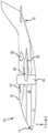
图7描绘了图1所示的垂直起降的飞行器的侧视图。FIG. 7 depicts a side view of the VTOL aircraft shown in FIG. 1 .
图8描绘了图2所示的垂直起降的飞行器的侧视图。FIG. 8 depicts a side view of the VTOL aircraft shown in FIG. 2 .
图9描绘了图2所示的垂直起降的飞行器的后视图,并且进一步地描绘了采用主体风扇下的叶片以提供偏航控制的实施方式。9 depicts a rear view of the VTOL aircraft shown in FIG. 2, and further depicts an embodiment employing blades under the main body fan to provide yaw control.
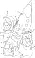
图10描绘了图2所示的垂直起降的飞行器的立体剖面图,并且进一步说明了发动机以及其进气口和排气口可以相对于机身和垂直起降飞行器的端口的风扇被放置的一种方式。FIG. 10 depicts a perspective cutaway view of the VTOL aircraft shown in FIG. 2 and further illustrates how the engine and its intake and exhaust ports may be positioned relative to the fuselage and the fans of the VTOL ports. a method.
图11描绘了图10所示的垂直起降的飞行器的俯视的剖面图。FIG. 11 depicts a top sectional view of the VTOL aircraft shown in FIG. 10 .
图12描绘了图10所示的垂直起降的飞行器的侧面剖视图。FIG. 12 depicts a side cross-sectional view of the VTOL aircraft shown in FIG. 10 .
图13描绘了本技术的垂直起降的飞行器的实施方式的透视示意图,并且说明了发动机和传输系统可以被耦接至涵道风扇的一种方式。13 depicts a perspective schematic view of an embodiment of a vertical take-off and landing aircraft of the present technology, and illustrates one manner in which an engine and transmission system may be coupled to a ducted fan.
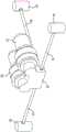
图14描绘了发动机和动力传输系统的等距视图,其被配置用于与本技术的垂直起降的飞行器的实施方式一起使用。14 depicts an isometric view of an engine and power transmission system configured for use with an embodiment of a vertical take-off and landing aircraft of the present technology.
图15示出了本技术的垂直起降的一个实施方式以及乘客客舱的一种配置的示意性立体图。Figure 15 shows a schematic perspective view of one embodiment of the vertical takeoff and landing of the present technology and one configuration of the passenger cabin.
图16示出了本技术的垂直起降的另一个实施方式以及乘客客舱的另一种配置的示意性立体图。16 shows a schematic perspective view of another embodiment of the vertical takeoff and landing of the present technology and another configuration of the passenger cabin.
具体实施方式Detailed ways
下面将参考附图更详细地描述实施方式,附图形成了实施方式的一部分并以图解的方式示出了具体的示例性实施方式。这些实施方式足够详细地被公开,以使本领域技术人员能够实践本发明。然而,实施方式可以不同的形式被实现,并且不应该被解释为限于在这里阐述的实施方式。因此,下面的详细描述不应被视为具有限制意义。Embodiments will be described in more detail below with reference to the accompanying drawings, which form a part hereof and illustrate specific exemplary embodiments by way of illustration. These embodiments are disclosed in sufficient detail to enable those skilled in the art to practice the invention. However, embodiments may be implemented in different forms and should not be construed as limited to the embodiments set forth herein. Accordingly, the following detailed description should not be considered in a limiting sense.
本技术的实施方式,由于它们涉及到垂直起降飞行器10,基本上被描绘在图1-16中。特别参考图1-9、图15和16,垂直起降飞行器10的实施方式包括机身12,其具有前端部分14、后端部分16,以及在前端部分14和后端部分16之间延伸的中心部分18。机身12的各种实施方式是细长的,定义了垂直起降飞行器10的中心纵向滚轴X。在至少一些实施方式中,机身12被提供为具有41英尺长和具有宽度78英寸的客舱。在一些实施方式中,如在图15和16中所描绘的,机身12的前端部分14可以被配置为有乘客以及飞行控制舱室。在各种实施例中,图15所描绘的,乘客和飞行控制舱室可被配置用于五人。这可以包括一到两名机组成员和三到四名乘客。在乘客和飞行控制舱室的后方,垂直起降飞行器10可以包括存储或载重舱。在其它实施方式中,垂直起降飞行器可以被增加大小以容纳更多的人和/或载重。例如,图16描绘了一个实施方式,其中乘客和飞行控制舱室可以被配置用于总共六个人。这可能包括一到两名机组人员和四到五名乘客。Embodiments of the present technology, as they relate to
一对机翼,特别是第一机翼20和第二机翼22,被相对于机身12被固定在固定的位置。该第一机翼20和第二机翼22的每一个由前缘部分24、后缘部分26、根端部28以及相对的尖端部分30所定义。第一机翼20和第二机翼22的根端28分别与机身12的中心部分18耦接,使得第一机翼20和第二机翼22从机身12侧向向外延伸。在至少某些实施方式中,第一机翼20和第二机翼22是掠翼设计,向垂直起降飞行器提供38英尺翼展和约240平方英尺的翼区。在某些实施方式中,机翼提供了垂直起降飞行器10小于80kts的失速速度。A pair of wings, particularly the
参考图2和图6,垂直起降飞行器10的各种实施方式包括向下排气的、涵道升力风扇32,其被置于机身12内,在垂直起降飞行器10的俯仰轴线Z和机身12的后端部分16之间。如在此使用的这个术语,“涵道风扇”仅仅是当空气通过涵道(duct)或护罩时加速空气的系统。相较于没有涵道时所发生的,该涵道用于主要诱导额外的空气量流动通过风扇桨叶。相较于无涵道的风扇或螺旋桨而言,这增加了“推力”,这是反应的力用于空气的加速。具体参照图2和图6,通过多桨叶风扇36,空气通过水平涵道34被加速。在所描绘的实施方式中,水平涵道34被定义为穿过机身12的开口,在垂直起降飞行器10的俯仰轴线Z的后面以及机身12的后端部分16的前方。可以设想,水平涵道34和机身12可一体成型或作为固定在固定位置的相对于彼此分离的结构。Referring to FIGS. 2 and 6 , various embodiments of the
参照图1、2、5、6和9,一组铰接的“蛤壳式(clam shell)”门盖或气窗(louver)37可与水平涵道34的底部出口开口相关联,并且可伸缩的盖子38可与顶部入口开口相关联。底部门盖37和可伸缩的盖子38将在各种实施方式中被提供,以选择性地在打开位置(在图1和5中描绘)和关闭位置(在图2和6中描绘)之间移动。特别是,底部门盖37和可伸缩的盖子38将被布置在打开位置,在那个位置升力风扇36被操作以通过水平涵道产生提升推力。在一些实施方式中,底部门盖37和可伸缩的盖子38将被放置在关闭位置,当垂直起降的飞行器在向前飞行中被操作,在该关闭位置,来自风扇36的提升推力是不期望的或不需要的。可以预期的是,底部门盖37和可伸缩的盖子38可以在前后伸缩或在相反的、侧向的方向上伸缩的多个部件中被提供。单个的可伸缩的盖子38也可以被使用,其在各种已知的方法上前后伸缩。在又一实施方式中,可以预期的是底部门盖37和可伸缩的盖子38可以作为多个气窗被提供,其在关闭和基本上打开的位置之间旋转。在一个这样的实施方式中,一个或多个气窗39可枢转地直接耦接到升力风扇36的下方并且在打开和关闭的位置以及它们之间的离散的点之间可移动。在关闭位置,气窗39形成底部门盖37的一部分以关闭水平涵道34的底部出口开口。这减少了底部门该37的外侧面板的尺寸。在垂直起降飞行器10的悬停飞行的过程中气窗39被设置在打开位置。气窗39和飞行控制的可操作的机械的或电子的耦接,如方向舵踏板或类似物,使得当在打开位置时气窗的选择性的角度设置。在水平涵道34的底部出口开口下方的选择性的角度位置可以被用于偏转水平涵道34的推力输出并且向垂直起降飞行器10提供偏航控制的方面。1, 2, 5, 6 and 9, a set of hinged "clam shell" doors or
参照图1-8,垂直起降飞行器10的实施方式包括一对涵道升力/推力风扇。特别是,该描绘的实施方式包括第一升力/推力风扇40和第二升力/推力风扇42,其分别与第一机翼20和第二机翼22耦接。在各实施方式中,第一升力/推力风扇40和第二升力/推力风扇42包括六英尺直径的五个桨叶旋翼41。旋翼41的实施方式额定超过700马力。可以预期的是,旋翼41的尺寸可以根据垂直起降飞行器10的尺寸和期望的性能特性来增加或减少。在一些实施方式中,旋翼41内的桨叶的距离可以根据所期望的输出性能进行变化。来自升力/推力风扇40和42的推力在各种实施方式中是独立可控的。1-8, an embodiment of a
第一升力/推力风扇40和第二升力/推力风扇42彼此对称地被置于垂直起降飞行器10的翻滚轴X的两侧,并且在俯仰轴Z的前方。以这种方式,并且在所有的一些实施方式中,升力风扇32和一对涵道升力/推力风扇40和42相对于彼此围绕以下至少一个被放置成三角形:第一机翼20和第二机翼22的升力的中心;升力风扇32和涵道升力/推力风扇40和42的升力的中心;以及垂直起降飞行器10的重力的中心。第一升力/推力风扇40和第二升力/推力风扇42与第一机翼20和第二机翼22耦接,使得它们选择性地、可旋转地在第一位置和第二位置之间移动,其中在第一位置它们提供垂直升力(图2)以及在第二位置它们提供水平推力(图1)。在一些实施方式中,第一升力/推力风扇40和第二升降/推力风扇42在第一和第二位置之间旋转,通过使用机械的、液压的,或电机的能够引起移动的致动器,当遭受到显著外力时,以及在需要时将装配锁定在一个位置。The first lift/
在所描述的实施方式中,第一机翼20和第二机翼22的每一个的前缘部分44包括曲线形风扇凹槽46。第一升力/推力风扇40和第二升力/推力风扇42的每一个被可旋转地放置在曲线形风扇凹槽46内。如所描绘的,本技术的实施方式将曲线形风扇凹槽46成形为近似第一升力/推力风扇40和第二升力/推力风扇42的周缘部分的形状。以这种方式,该第一升力/推力风扇40和第二升力/推力风扇42可被水平设置在曲线形风扇凹槽46的套子(nest)内。曲线形凹槽46允许第一升力/推力风扇40和第二升力/推力风扇42被置于后方,紧密靠近垂直起降飞行器10的俯仰轴Z。前缘部分44包括相对的成对的装配肩48,其向前突出以接近于在第一升力/推力风扇40和第二升力/推力风扇42上的枢轴点枢转地啮合第一升力/推力风扇40和第二升力/推力风扇42。在一些实施方式中,第一机翼20和第二机翼22设置有后掠。这使得第一升力/推力风扇40和第二升力/推力风扇42被定位在根端28与第一机翼20和第二机翼22的相对尖端部分30的中间。当第一升力/推力风扇40和第二升力/推力风扇42的位置从第一机翼20和第二机翼22的尖端部分30向内移动时,整个第一机翼20和第二机翼22需要更少的结构性稳固支撑,这减少了垂直起降飞行器10的整体的重量。In the depicted embodiment, the leading edge portion 44 of each of the
参考图10-14,垂直起降飞行器10包括动力装置以及电力传输系统,其提供电力至升力风扇32、第一升力/推力风扇40和第二升力/推力风扇42。能够预期的是,单独的发动机可被用来将电力提供给垂直起降飞行器10。然而,所描绘的实施方式包括第一发动机50和第二发动机52,其被彼此分开放置在第一机翼20和第二机翼22之间的机身12内。在一个具体的实施方式中,第一发动机50和第二发动机52各自至少与具有超过2,000马力的最大额定海平面功率的发动机相匹敌。如在图10和11所描绘的,一对相对的NACA式空气入口涵道54从第一发动机50和第二发动机52向前穿过机身。一对排气口56从第一发动机50和第二发动机52的通过并且穿过机身12的中心部分18的相对侧。Referring to FIGS. 10-14 , the
进一步参考图14,与垂直起降飞机10一起使用的示例性电力传输系统包括齿轮箱58,其接收来自第一发动机50和第二发动机52的电力输出。在所描绘的实施方式中,第一输出轴60和第二输出轴62从齿轮箱58横向地延伸,并啮合第一减速齿轮64和第二减速齿轮66,其分别与第一升力/推力风扇40和第二升力/推力风扇42相关联。第三输出轴68从齿轮箱58向后延伸并与升力风扇32相关联的第三减速齿轮69啮合。在各种实施方式中,可以设想,本文所描述的输出轴可以被提供为双轴、同轴的轴,其提供冗余至电力传输系统。With further reference to FIG. 14 , an exemplary power transfer system for use with the
垂直起降飞行器10包括通过各种飞行操作来操作垂直起降飞行器10的飞行控制系统。飞行操作的方面将被监控,并且在某些情况下,直接由飞行控制计算机控制。与飞行控制计算机相关联的处理器将接收来自一个或多个相关联的系统的数据输入。例如,飞行控制系统的实施方式包括多个导频输入,将数据发射到飞行控制计算机。这些导频输入包括,但不限于,来自飞行控制杆的俯仰和翻滚命令,来自方向舵踏板的偏航,配平命令,以及来自发动机油门控制的电力命令。在各种实施方式中,飞行控制系统可操作地与飞行器控制表面耦接,其包括升降舵、副翼,和方向舵。在一些实施方式中,飞行控制系统可操作地与涵道升力/推力风扇以及升力风扇耦接,以一种允许飞行器控制表面、涵道升力/推力风扇40和42、以及升力风扇36的在功能上的选择性控制的方式。在一些这样的实施方式中,飞行控制系统允许涵道升力/推力风扇40和42、以及升力风扇36的风扇桨距、功率或旋转速度的选择性控制。垂直起降飞行器10的实施方式进一步包括运动传感器/加速计,用于测量在X、Y和Z轴的飞行器加速度。可以提供速率陀螺仪来接收和中继有关俯仰、偏航和翻滚的旋转角的数据。一个或多个传感器检测起落架70伸缩和展开状态。各种外围系统提供环境数据到飞行控制计算机,包括高度计、空气数据传感器系统、空速管(pitot-static probe)和总温度探针。来自这样的外围系统的数据在飞行控制计算机中被处理,其可在一个或多个相关联的存储器存储系统内存储这种数据。一个或多个显示器或多功能显示器向机组人员中继该飞行控制的状态。The
垂直起降飞行器10的实施方式包括紧急降落伞系统用于在垂直起降飞行器10遭受完全的或显著的推进故障或没有足够的空速来执行滑翔迫降时使用。一些这样的实施方式包括一个或多个降落伞,其主要在垂直起降飞行器10处于悬停模式或在低速行进的情况下被使用。紧急降落伞系统的实施方式在机身12内的舱室内固定降落伞,邻近其后端部分16。支撑降落伞电缆被耦接到机体。在一些实施方式中,,如果发动机断电或垂直起降飞行器10在悬停模式变得不稳定,紧急降落伞通过飞行员输入由飞行员部署或自动地通过飞行控制计算机被部署。在一些实施方式,紧急降落伞系统部署火箭,其从机身12以某角度射出并在相反的方向上拉动降落伞的末端,从而部署舱罩(canopy)。如果垂直起降飞行器10正在向前飞行,飞行控制计算机可以被编程以从一个或多个控制传感器接收数据,以确定在速度很快的情况下降落伞的部署是否需要延迟。Embodiments of the
垂直起降飞行器10的飞行控制系统,如上所述,简化了垂直起飞和着陆的操作,以及在悬停模式和向前飞行模式之间转换。例如,操作者启动垂直起飞,通过将升力/推进风扇置于第一、起飞位置以使得其推力朝向地面,如图2中所示。操作者使得飞行员输入启动开始模式。在飞行控制计算机内接收的数据驱动底部门盖37以及可伸缩的盖子38以移动为打开位置。启动序列然后启动升力风扇32、第一升力/推力风扇40,和第二升力/推力风扇42。飞行控制系统允许风扇达到怠速状态。当升力风扇32,第一升力/推力风扇40,和第二升力/推力风扇42的推力到达确定的值或更大时,操作者采用来自与飞行控制系统相关联的飞行员输入的悬停模式。升力风扇32、第一升力/推力风扇40,和第二升力/推力风扇42的推力被增加,直至垂直起降飞行器10升空。The flight control system of the
随着垂直起降飞行器10以稳定的方式悬停,操作者从与飞行控制计算器相关联的飞行员输入选择巡航模式。信号被从飞行控制计算机发送以逐渐倾斜第一升力/推力风扇40和第二升力/推力风扇42从第一位置移动到第二位置,以便产生向前的移动力。当垂直起降飞行器10加速到向前飞行时,升力在机翼上被产生并且垂直起降飞行器10巡航,具有第一升力/推力风扇40和第二升力/推力风扇42被引导向后。然后操作者可以通过控制杆和转向踏板执行手动操作。同时,或在替代方式中,飞行操作可以留给自动操作,其基于从与飞行控制计算机相关联的外围传感器和系统接收的数据来执行。With the
本技术的垂直起降飞行器10提供了处置起飞和着陆的飞行器,其可以高速巡航并且不需要用于起飞和着陆的跑道,因为其可以从地面春之起飞并垂直着陆在地面上。在至少一些实施方式中,垂直起降飞行器10具有小于5000磅的总重量(空)。各种实施方式中的垂直起降飞行器承受超过6000磅的最大垂直起降起飞重量。垂直起降飞行器10的这样的实施方式可以以10度爬升角的240kts的巡航速度在垂直起飞的90秒以内达到约2,000英尺的高度,3海里的下降范围。的高空有当需要时,垂直起降飞行器10也可以执行短距起落(STOL)或常规的起飞和着陆。本技术的实施方式允许在跑道上小于700英尺的起飞和降落,具有第一升力/推力风扇40和第二升力/推力风扇42处于第一位置(向前飞行),具有超过7000磅的最大短距起落起飞重量。起飞跑道距离可缩短到大约300英尺,其中第一升力/推力风扇40和第二升力/推力风扇42在第一位置和第二位置之间被向上旋转40度。在这样的实施方式中,垂直起降飞行器将提供1200海里的美国公务航空协会(NBAA)目视飞行(VFR)范围和1100海里的NBAA仪表飞行(IFR)范围(在240KTAS巡航速度,在29000英尺的高度被计算的)。The vertical take-off and
尽管本技术用某些特定结构、材料和方法步骤来加以描述,但可以理解的是,所附权利要求所界定的发明不必局限于所述的特定结构、材料和/或步骤。实际上,所述的特定方面和步骤只是用来实施所要求的本发明的形式。由于在不偏离本发明的精神和范围的情况下可实施本发明的多个实施方式,因此本发明以下文所附的权利要求为准。除非另外指明,所有在说明书(除了权利要求书)中使用的数字和表达,例如那些表示尺寸、物理特征等等,被理解为在所有情形下由术语“大约”修饰。至少,不试图限制对权利要求等同原则的应用,在说明书或权利要求中叙述的由术语“大约”修饰的每一个数值参数应该至少是鉴于叙述的有效位的数字并通过应用四舍五入技术来解释的。此外,本文所公开的所有范围要理解为包括叙述任何和全部子范围的权利要求或在其中包含的所有或单个值并为其提供支持。例如,所陈述的1到10的范围应该被认为包括所有在最小值1和最大值10之间并包括最小值1和最大值10的任何范围和全部子范围或单个的值;也即,所有的由最小值1或者更大的数开始并由最大值10或更小的数结束的子范围(例如,5.5到10,2.34到3.56,等等)或者任何从1到10的值(例如3,5.8,9.9994等等)。Although the present technology has been described in terms of certain specific structures, materials and method steps, it is to be understood that the invention as defined by the appended claims is not necessarily limited to the specific structures, materials and/or steps described. Indeed, the specific aspects and steps described are merely forms of carrying out the claimed invention. Since various embodiments of the present invention may be practiced without departing from the spirit and scope of the present invention, the present invention is governed by the following claims. Unless otherwise indicated, all numbers and expressions used in the specification (except in the claims), such as those indicating dimensions, physical characteristics, etc., are understood to be modified in all instances by the term "about". At the very least, and without intending to limit the application of the doctrine of equivalents to the claims, each numerical parameter recited in the specification or claims that is modified by the term "about" should be construed at least in light of the number of significant digits recited and by applying rounding techniques . Furthermore, all ranges disclosed herein are to be understood to include and support the claims reciting any and all subranges or all or individual values contained therein. For example, a recited range of 1 to 10 should be considered to include all ranges and all subranges or individual values between and including a minimum value of 1 and a maximum value of 10; that is, all A subrange of a value that begins with a minimum value of 1 or greater and ends with a maximum value of 10 or less (for example, 5.5 to 10, 2.34 to 3.56, etc.) or any value from 1 to 10 (for example, 3 , 5.8, 9.9994, etc.).
Claims (21)
Translated fromChinesePriority Applications (1)
| Application Number | Priority Date | Filing Date | Title |
|---|---|---|---|
| CN201911262704.5ACN111498109B (en) | 2014-05-07 | 2015-05-07 | Vertical take-off and landing aircraft |
Applications Claiming Priority (3)
| Application Number | Priority Date | Filing Date | Title |
|---|---|---|---|
| US201461989935P | 2014-05-07 | 2014-05-07 | |
| US61/989,935 | 2014-05-07 | ||
| PCT/US2015/029751WO2016018486A2 (en) | 2014-05-07 | 2015-05-07 | Vtol aircraft |
Related Child Applications (1)
| Application Number | Title | Priority Date | Filing Date |
|---|---|---|---|
| CN201911262704.5ADivisionCN111498109B (en) | 2014-05-07 | 2015-05-07 | Vertical take-off and landing aircraft |
Publications (2)
| Publication Number | Publication Date |
|---|---|
| CN107074358A CN107074358A (en) | 2017-08-18 |
| CN107074358Btrue CN107074358B (en) | 2020-01-07 |
Family
ID=55218435
Family Applications (2)
| Application Number | Title | Priority Date | Filing Date |
|---|---|---|---|
| CN201580036794.XAActiveCN107074358B (en) | 2014-05-07 | 2015-05-07 | vertical take-off and landing aircraft |
| CN201911262704.5AActiveCN111498109B (en) | 2014-05-07 | 2015-05-07 | Vertical take-off and landing aircraft |
Family Applications After (1)
| Application Number | Title | Priority Date | Filing Date |
|---|---|---|---|
| CN201911262704.5AActiveCN111498109B (en) | 2014-05-07 | 2015-05-07 | Vertical take-off and landing aircraft |
Country Status (7)
| Country | Link |
|---|---|
| US (1) | US9676479B2 (en) |
| EP (1) | EP3140190B1 (en) |
| JP (1) | JP6191039B2 (en) |
| CN (2) | CN107074358B (en) |
| BR (1) | BR112016025875B1 (en) |
| CA (1) | CA2947974C (en) |
| WO (1) | WO2016018486A2 (en) |
Cited By (1)
| Publication number | Priority date | Publication date | Assignee | Title |
|---|---|---|---|---|
| CN111498109B (en)* | 2014-05-07 | 2024-03-29 | Xti飞行器公司 | Vertical take-off and landing aircraft |
Families Citing this family (90)
| Publication number | Priority date | Publication date | Assignee | Title |
|---|---|---|---|---|
| KR101287624B1 (en)* | 2013-02-25 | 2013-07-23 | 주식회사 네스앤텍 | Unmanned aerial vehicle for easily landing |
| EP3169586B1 (en)* | 2014-07-18 | 2020-04-08 | Pegasus Universal Aerospace (Pty) Ltd. | Vertical take-off and landing aircraft |
| US9889924B2 (en)* | 2015-08-24 | 2018-02-13 | The Boeing Company | Multi-directional control using upper surface blowing systems |
| US9908615B2 (en)* | 2015-10-26 | 2018-03-06 | Sikorsky Aircraft Corporation | Rotor blown wing aircraft including a rotor blown wing having at least one selectively controllable control surface and a method of controlling a rotor blown wing aircraft |
| US9856018B2 (en)* | 2016-01-11 | 2018-01-02 | The Boeing Company | Ducted fan doors for aircraft |
| US10926874B2 (en)* | 2016-01-15 | 2021-02-23 | Aurora Flight Sciences Corporation | Hybrid propulsion vertical take-off and landing aircraft |
| CN105711831B (en)* | 2016-04-25 | 2018-03-06 | 长江大学 | The fixed-wing unmanned plane of VTOL |
| US10279900B2 (en) | 2016-08-10 | 2019-05-07 | Bell Helicopter Textron Inc. | Rotorcraft variable thrust cross-flow fan systems |
| US10106253B2 (en)* | 2016-08-31 | 2018-10-23 | Bell Helicopter Textron Inc. | Tilting ducted fan aircraft generating a pitch control moment |
| US10421541B2 (en) | 2016-08-10 | 2019-09-24 | Bell Helicopter Textron Inc. | Aircraft with tilting cross-flow fan wings |
| US10479495B2 (en) | 2016-08-10 | 2019-11-19 | Bell Helicopter Textron Inc. | Aircraft tail with cross-flow fan systems |
| US10377480B2 (en) | 2016-08-10 | 2019-08-13 | Bell Helicopter Textron Inc. | Apparatus and method for directing thrust from tilting cross-flow fan wings on an aircraft |
| US10293931B2 (en) | 2016-08-31 | 2019-05-21 | Bell Helicopter Textron Inc. | Aircraft generating a triaxial dynamic thrust matrix |
| US10562623B1 (en) | 2016-10-21 | 2020-02-18 | Birdseyeview Aerobotics, Llc | Remotely controlled VTOL aircraft |
| GB2555440A (en)* | 2016-10-27 | 2018-05-02 | Mono Aerospace Ip Ltd | Vertical take off and landing aircraft |
| GB2555439A (en)* | 2016-10-27 | 2018-05-02 | Mono Aerospace Ip Ltd | Vertical take-off and landing aircraft and control method |
| US10513333B2 (en)* | 2017-01-14 | 2019-12-24 | Spydar Sensors, Inc. | Ducted fan propulsion engine |
| US10384776B2 (en) | 2017-02-22 | 2019-08-20 | Bell Helicopter Textron Inc. | Tiltrotor aircraft having vertical lift and hover augmentation |
| US10676187B2 (en)* | 2017-03-07 | 2020-06-09 | The Boeing Company | Robust amphibious aircraft |
| WO2018193522A1 (en)* | 2017-04-18 | 2018-10-25 | インダストリーネットワーク株式会社 | Propeller aircraft |
| TWI625270B (en)* | 2017-04-19 | 2018-06-01 | 威拓動力有限公司 | Triaxial helicopter |
| US11111033B1 (en) | 2017-05-12 | 2021-09-07 | Phirst Technologies, Llc | Unmanned aerial vehicle recharging system |
| US11279481B2 (en) | 2017-05-12 | 2022-03-22 | Phirst Technologies, Llc | Systems and methods for tracking, evaluating and determining a response to emergency situations using unmanned airborne vehicles |
| TWI627104B (en)* | 2017-05-31 | 2018-06-21 | 大鵬航太有限公司 | Simple Pitch Control Device for Dual-Mode Aircraft with VTOL and Fixed-Wing Flight |
| US20180346112A1 (en)* | 2017-05-31 | 2018-12-06 | Hsun-Yin Chiang | Simple pitch control device for dual-mode aircraft with vtol and fixed-wing flight |
| US10822101B2 (en) | 2017-07-21 | 2020-11-03 | General Electric Company | Vertical takeoff and landing aircraft having a forward thrust propulsor |
| CN107512393A (en)* | 2017-08-09 | 2017-12-26 | 深圳中翼特种装备制造有限公司 | A kind of rapid vertical landing fixed-wing unmanned plane |
| US10814967B2 (en) | 2017-08-28 | 2020-10-27 | Textron Innovations Inc. | Cargo transportation system having perimeter propulsion |
| JP6879866B2 (en)* | 2017-08-28 | 2021-06-02 | 本田技研工業株式会社 | Vertical takeoff and landing aircraft |
| WO2019062256A1 (en)* | 2017-09-29 | 2019-04-04 | 清华大学 | Single lift force ducted vertical take-off and landing aircraft based on tilt duct |
| CN107539472A (en)* | 2017-09-29 | 2018-01-05 | 清华大学 | A Single Lift Duct VTOL Aircraft Based on Tilting Duct |
| CN107628244A (en)* | 2017-09-29 | 2018-01-26 | 清华大学 | A Dual-Lift Duct VTOL Aircraft Based on Tilting Duct |
| US11001384B2 (en)* | 2017-10-02 | 2021-05-11 | Bell Helicopter Textron Inc. | Hybrid power systems for aircraft |
| EP3470332B1 (en) | 2017-10-13 | 2020-04-22 | AIRBUS HELICOPTERS DEUTSCHLAND GmbH | A multirotor aircraft with an airframe and at least one wing |
| CN107640318A (en)* | 2017-10-15 | 2018-01-30 | 天津飞眼无人机科技有限公司 | Oil electric mixed dynamic fixed-wing unmanned plane |
| CN108082466A (en)* | 2017-11-23 | 2018-05-29 | 北京航空航天大学 | A kind of tilting duct connection wing layout vertically taking off and landing flyer |
| WO2019116101A1 (en)* | 2017-12-12 | 2019-06-20 | Spencer Cameron | Variable-geometry vertical take-off and landing (vtol) aircraft system |
| DE102017130809A1 (en)* | 2017-12-20 | 2019-06-27 | Airbus Defence and Space GmbH | Device for driving an aircraft and aircraft comprising this device |
| KR102010424B1 (en)* | 2017-12-21 | 2019-08-14 | 한국항공우주연구원 | A method and computer program for controlling the tilt angle of the main rotor based on the pitch attitude control signal in the low speed region |
| WO2019124686A1 (en)* | 2017-12-21 | 2019-06-27 | 한국항공우주연구원 | Method and computer program for controlling tilt angle of main rotor on basis of vertical attitude control signal low-speed flight state, and vertical take-off and landing aircraft |
| CN108109473B (en)* | 2018-02-02 | 2024-06-04 | 安徽英釜航空科技有限公司 | Foot rudder linkage device of flight simulator |
| CN108163191A (en)* | 2018-02-24 | 2018-06-15 | 金羽飞 | Aircraft with a flight control device |
| CN108298074A (en)* | 2018-03-14 | 2018-07-20 | 长沙市云智航科技有限公司 | The component that verts for the more rotor flying vehicles of manned duct |
| AU2019257746B2 (en)* | 2018-04-27 | 2023-11-02 | Textron Systems Corporation | Variable pitch rotor assembly for electrically driven vectored thrust aircraft applications |
| US10933991B2 (en)* | 2018-06-18 | 2021-03-02 | Aurora Flight Sciences Corporation | Propulsors, aircraft including the propulsors, and methods of directing a fluid stream in a propulsor |
| DE102018116154B4 (en)* | 2018-07-04 | 2022-09-01 | Dr. Ing. H.C. F. Porsche Aktiengesellschaft | aircraft |
| DE102018116168A1 (en)* | 2018-07-04 | 2020-01-09 | Dr. Ing. H.C. F. Porsche Aktiengesellschaft | aircraft |
| DE102018116147A1 (en)* | 2018-07-04 | 2020-01-09 | Dr. Ing. H.C. F. Porsche Aktiengesellschaft | aircraft |
| US11926429B2 (en)* | 2018-07-04 | 2024-03-12 | Dr. Ing. H.C. F. Porsche Aktiengesellschaft | Aircraft having cooling system for distributing heat transfer liquid to different regions of aircraft |
| CN110723284A (en)* | 2018-07-17 | 2020-01-24 | 刘建国 | Vertical lifting fixed wing aircraft with tiltable ducted fan |
| US10829199B2 (en)* | 2018-08-20 | 2020-11-10 | Bell Helicopter Textron Inc. | Active airflow management for tiltrotor hub thermal ventilation |
| WO2020097367A1 (en)* | 2018-11-09 | 2020-05-14 | Karem Aircraft, Inc. | Vertical flight aircraft with improved stability |
| US11148799B2 (en)* | 2018-11-26 | 2021-10-19 | Textron Innovations Inc. | Tilting duct compound helicopter |
| US10787255B2 (en)* | 2018-11-30 | 2020-09-29 | Sky Canoe Inc. | Aerial vehicle with enhanced pitch control and interchangeable components |
| US20200216189A1 (en)* | 2019-01-03 | 2020-07-09 | Bell Textron Inc. | Display system |
| EP3730404B1 (en) | 2019-04-23 | 2021-08-18 | LEONARDO S.p.A. | Vertical take-off and landing aircraft and related control method |
| EP3966047A4 (en)* | 2019-05-07 | 2023-01-11 | NFT Inc. | Drive and fly electric and hybrid vtol vehicle |
| DE102019112132B4 (en)* | 2019-05-09 | 2024-05-23 | Dr. Ing. H.C. F. Porsche Aktiengesellschaft | Aircraft |
| CN110155315A (en)* | 2019-06-09 | 2019-08-23 | 西北工业大学 | An unmanned vertical take-off and landing aircraft driven by a gasoline-electric hybrid and its flight control method |
| US11536565B2 (en)* | 2019-06-21 | 2022-12-27 | Textron Innovations Inc. | System and method for gimbal lock avoidance in an aircraft |
| US11656632B2 (en)* | 2019-07-12 | 2023-05-23 | The Boeing Company | Takeoff/landing stability augmentation by active wind gust sensing |
| US11661193B2 (en)* | 2019-07-18 | 2023-05-30 | Elroy Air, Inc. | Unmanned aerial vehicle optimization |
| US11427313B2 (en) | 2019-10-15 | 2022-08-30 | Helmuth G. Bachmann | Universally attachable hinged wing and VLOS aid for mutirotor drones |
| CN111017205A (en)* | 2019-12-24 | 2020-04-17 | 中国航空工业集团公司西安飞机设计研究所 | A vertical take-off and landing transport aircraft |
| US11554865B2 (en) | 2020-02-18 | 2023-01-17 | Aurora Flight Sciences Corporation | Vertical take-off and landing (VTOL) aircraft and related methods |
| USD1009696S1 (en) | 2020-02-18 | 2024-01-02 | Aurora Flight Sciences Corporation, a subsidiary of The Boeing Company | Aircraft |
| USD945947S1 (en) | 2020-02-24 | 2022-03-15 | Aurora Flight Sciences Corporation | Aircraft |
| US11472546B2 (en) | 2020-02-24 | 2022-10-18 | Aurora Flight Sciences Corporation | Fixed-wing short-takeoff-and-landing aircraft and related methods |
| CN111422348B (en)* | 2020-04-02 | 2021-11-16 | 沈阳航空航天大学 | Vertical take-off and landing unmanned aerial vehicle and control method thereof |
| CN111907274B (en)* | 2020-07-22 | 2023-09-08 | 淮阴工学院 | A ducted fan opening and closing device and its use method |
| CN112124569B (en)* | 2020-09-17 | 2022-04-01 | 西安电子科技大学 | Vertical take-off and landing and unmanned aerial vehicle stabilizing system based on launching canister |
| CN112373702B (en)* | 2020-11-24 | 2022-07-05 | 中国航空发动机研究院 | Back-support type wing-body fusion body aircraft propulsion system and control method thereof |
| WO2022113086A1 (en)* | 2020-11-30 | 2022-06-02 | Efix Aviation Ltd | Rotorcraft |
| WO2022113087A1 (en)* | 2020-11-30 | 2022-06-02 | Efix Aviation Ltd | Rotorcraft |
| CN112340013A (en)* | 2020-12-12 | 2021-02-09 | 江西洪都航空工业股份有限公司 | Fixed wing aircraft with tiltable duct |
| DE102020007834A1 (en) | 2020-12-21 | 2022-06-23 | BAAZ GmbH | Aircraft and associated operating procedures |
| US11772773B2 (en) | 2021-01-04 | 2023-10-03 | Aurora Flight Sciences Corporation, a subsidiary of The Boeing Company | Aircraft and related methods |
| CN112896500A (en)* | 2021-03-08 | 2021-06-04 | 四川腾盾科技有限公司 | Aircraft with four ducts in tilting layout |
| JP7610449B2 (en)* | 2021-03-29 | 2025-01-08 | 本田技研工業株式会社 | aircraft |
| US11447244B1 (en) | 2021-06-29 | 2022-09-20 | Beta Air, Llc | System and method for airspeed estimation utilizing propulsor data in electric vertical takeoff and landing aircraft |
| CN113830303A (en)* | 2021-11-12 | 2021-12-24 | 娄方远 | Vertical take-off and landing fixed wing aircraft |
| CN114194388A (en)* | 2021-11-23 | 2022-03-18 | 上海羽天航空科技有限公司 | A new type of vertical take-off and landing fixed-wing aircraft |
| US11859542B2 (en)* | 2021-12-20 | 2024-01-02 | Rolls-Royce North American Technologies, Inc. | Dual power lift system |
| CN115180138A (en)* | 2022-07-22 | 2022-10-14 | 中国民航大学 | Novel overall arrangement VTOL fixed wing unmanned aerial vehicle |
| USD1048933S1 (en)* | 2022-11-14 | 2024-10-29 | Yao-Chang Lin | Unmanned aerial vehicle |
| JP2024142914A (en)* | 2023-03-30 | 2024-10-11 | 本田技研工業株式会社 | aircraft |
| WO2024226576A1 (en)* | 2023-04-24 | 2024-10-31 | XTI Aircraft Company | V/stol aircraft |
| CN116714401A (en)* | 2023-04-28 | 2023-09-08 | 重庆中岳航空航天装备智能制造有限公司 | A vertical take-off and landing flying car |
| US20240375799A1 (en)* | 2023-05-11 | 2024-11-14 | United States Of America As Represented By The Administration Of Nasa | Vtol aircraft capable of flying forward and backward |
| US12428141B2 (en) | 2023-06-01 | 2025-09-30 | Efix Aviation Ltd | Fixed wing rotorcraft |
Citations (5)
| Publication number | Priority date | Publication date | Assignee | Title |
|---|---|---|---|---|
| CN101274666A (en)* | 2007-11-05 | 2008-10-01 | 穆骞 | Split type wing |
| CN101643116A (en)* | 2009-08-03 | 2010-02-10 | 北京航空航天大学 | Tiltrotor controlled by double-propeller vertical duct |
| CN101875399A (en)* | 2009-10-30 | 2010-11-03 | 北京航空航天大学 | A kind of tilt rotor aircraft adopting side-by-side coaxial twin rotors |
| CN103832585A (en)* | 2012-11-22 | 2014-06-04 | 上海市浦东新区知识产权保护协会 | Cruise aircraft |
| CN104176250A (en)* | 2013-05-23 | 2014-12-03 | 中国直升机设计研究所 | Vertical take-off and landing rotor aircraft with ducts built in wings |
Family Cites Families (49)
| Publication number | Priority date | Publication date | Assignee | Title |
|---|---|---|---|---|
| US204108A (en) | 1878-05-21 | Improvement in piano-fortes | ||
| BE407576A (en)* | ||||
| US1783458A (en)* | 1929-02-25 | 1930-12-02 | Albert E Grimm | Vertical-lift airplane |
| US1841815A (en)* | 1930-04-30 | 1932-01-19 | Charles J Hughes | Aircraft |
| US1987788A (en)* | 1932-12-03 | 1935-01-15 | Benjamin A Morton | Aircraft |
| US2700425A (en) | 1950-09-12 | 1955-01-25 | Arthur E Voglewede | Rotary wing for airplanes |
| US3083936A (en)* | 1959-02-18 | 1963-04-02 | Scott C Rethorst | Aircraft |
| US3335977A (en)* | 1965-06-16 | 1967-08-15 | Ludwig F Meditz | Convertiplane |
| DE1481542A1 (en) | 1967-01-18 | 1969-03-20 | Entwicklungsring Sued Gmbh | Especially designed for VTOL aircraft |
| US3638884A (en)* | 1969-09-15 | 1972-02-01 | Us Air Force | Thrust vectoring louver cascade |
| GB1259545A (en) | 1969-11-28 | 1972-01-05 | ||
| US4022405A (en) | 1976-03-25 | 1977-05-10 | The United States Of America As Represented By The Secretary Of The Navy | Fan lift-cruise v/stol aircraft |
| USD274511S (en) | 1982-03-01 | 1984-07-03 | Clifton Robert T | Vertical/short take-off/landing aircraft |
| USD274512S (en) | 1982-03-01 | 1984-07-03 | Clifton Robert T | Vertical/short take-off/landing aircraft |
| USD302676S (en) | 1985-11-18 | 1989-08-08 | Vulcan Aircraft Corporation | Vertical short takeoff and landing aircraft |
| USD311719S (en) | 1988-09-30 | 1990-10-30 | The Ishida Foundation | Aircraft |
| US5419514A (en) | 1993-11-15 | 1995-05-30 | Duncan; Terry A. | VTOL aircraft control method |
| US5597137A (en) | 1994-12-28 | 1997-01-28 | Skoglun; Willard | Vertical take-off and landing aircraft |
| KR0150340B1 (en)* | 1995-05-10 | 1998-09-15 | 정수철 | Aircar combines both ground and air |
| US6886776B2 (en) | 2001-10-02 | 2005-05-03 | Karl F. Milde, Jr. | VTOL personal aircraft |
| JP2003137192A (en)* | 2001-10-31 | 2003-05-14 | Mitsubishi Heavy Ind Ltd | Vertical taking-off/landing craft |
| JP3861224B2 (en) | 2001-12-07 | 2006-12-20 | 有限会社新科学開発研究所 | Aerial vehicle |
| USD493411S1 (en) | 2001-12-18 | 2004-07-27 | Peter Sui Lun Fong | Space ship |
| US6843447B2 (en)* | 2003-01-06 | 2005-01-18 | Brian H. Morgan | Vertical take-off and landing aircraft |
| USD500008S1 (en) | 2004-02-20 | 2004-12-21 | Robert Bulaga | Aircraft |
| US7472863B2 (en) | 2004-07-09 | 2009-01-06 | Steve Pak | Sky hopper |
| US20070246601A1 (en) | 2004-10-07 | 2007-10-25 | Layton Otis F | Manned/unmanned V.T.O.L. flight vehicle |
| US7735774B2 (en) | 2004-12-02 | 2010-06-15 | Sonic Blue Aerospace, Inc. | VTOL aircraft with forward-swept fixed wing |
| WO2006069291A2 (en)* | 2004-12-22 | 2006-06-29 | Aurora Flight Sciences Corporation | System and method for utilizing stored electrical energy for vtol aircraft thrust enhancement and attitude control |
| US7267300B2 (en)* | 2005-02-25 | 2007-09-11 | The Boeing Company | Aircraft capable of vertical and short take-off and landing |
| JPWO2006103774A1 (en)* | 2005-03-30 | 2008-09-04 | 力也 石川 | Vertically movable aircraft |
| US20070018035A1 (en) | 2005-07-20 | 2007-01-25 | Saiz Manuel M | Lifting and Propulsion System For Aircraft With Vertical Take-Off and Landing |
| US8152096B2 (en) | 2005-10-18 | 2012-04-10 | Smith Frick A | Apparatus and method for vertical take-off and landing aircraft |
| US7874513B1 (en) | 2005-10-18 | 2011-01-25 | Smith Frick A | Apparatus and method for vertical take-off and landing aircraft |
| US8720814B2 (en)* | 2005-10-18 | 2014-05-13 | Frick A. Smith | Aircraft with freewheeling engine |
| US8181903B2 (en) | 2006-03-03 | 2012-05-22 | David Posva | Aircraft having the ability for hovering flight, fast forward flight, gliding flight, short take-off, short landing, vertical take-off and vertical landing |
| US7410122B2 (en) | 2006-03-20 | 2008-08-12 | The Boeing Company | VTOL UAV with lift fans in joined wings |
| US8205820B2 (en)* | 2009-02-03 | 2012-06-26 | Honeywell International Inc. | Transforming unmanned aerial-to-ground vehicle |
| IL199009A (en)* | 2009-05-27 | 2013-11-28 | Israel Aerospace Ind Ltd | Air vehicle |
| EP2668097A4 (en)* | 2011-01-24 | 2016-07-13 | Frick A Smith | Apparatus and method for vertical take-off and landing aircraft |
| TWI538852B (en)* | 2011-07-19 | 2016-06-21 | 季航空股份有限公司 | Personal aircraft |
| PT2551190E (en)* | 2011-07-29 | 2014-01-23 | Agustawestland Spa | Convertiplane |
| EP2551193B1 (en) | 2011-07-29 | 2016-04-13 | AGUSTAWESTLAND S.p.A. | Convertiplane |
| USD665333S1 (en) | 2011-08-16 | 2012-08-14 | Garreau Oliver | VTOL aircraft |
| IL217501A (en) | 2012-01-12 | 2017-09-28 | Israel Aerospace Ind Ltd | System and method for maneuvering of an air vehicle |
| US9022312B2 (en) | 2012-12-03 | 2015-05-05 | Patrick A. Kosheleff | Fly-in landing pad for lift-fan aircraft |
| FR2999150B1 (en)* | 2012-12-10 | 2015-10-09 | Bermond Gerome Maurice Paul | CONVERTIBLE AIRCRAFT COMPRISING TWO CAREN ROTORS AT THE END OF A WING AND A HORIZONTAL FAN IN FUSELAGE |
| CN103448910A (en)* | 2013-08-31 | 2013-12-18 | 西北工业大学 | Aircraft capable of vertically taking off and landing at high speed |
| CN107074358B (en)* | 2014-05-07 | 2020-01-07 | Xti飞行器公司 | vertical take-off and landing aircraft |
- 2015
- 2015-05-07CNCN201580036794.XApatent/CN107074358B/enactiveActive
- 2015-05-07BRBR112016025875-4Apatent/BR112016025875B1/enactiveIP Right Grant
- 2015-05-07CNCN201911262704.5Apatent/CN111498109B/enactiveActive
- 2015-05-07WOPCT/US2015/029751patent/WO2016018486A2/enactiveApplication Filing
- 2015-05-07JPJP2016566259Apatent/JP6191039B2/enactiveActive
- 2015-05-07CACA2947974Apatent/CA2947974C/enactiveActive
- 2015-05-07EPEP15827223.7Apatent/EP3140190B1/enactiveActive
- 2015-05-07USUS14/706,407patent/US9676479B2/enactiveActive
Patent Citations (5)
| Publication number | Priority date | Publication date | Assignee | Title |
|---|---|---|---|---|
| CN101274666A (en)* | 2007-11-05 | 2008-10-01 | 穆骞 | Split type wing |
| CN101643116A (en)* | 2009-08-03 | 2010-02-10 | 北京航空航天大学 | Tiltrotor controlled by double-propeller vertical duct |
| CN101875399A (en)* | 2009-10-30 | 2010-11-03 | 北京航空航天大学 | A kind of tilt rotor aircraft adopting side-by-side coaxial twin rotors |
| CN103832585A (en)* | 2012-11-22 | 2014-06-04 | 上海市浦东新区知识产权保护协会 | Cruise aircraft |
| CN104176250A (en)* | 2013-05-23 | 2014-12-03 | 中国直升机设计研究所 | Vertical take-off and landing rotor aircraft with ducts built in wings |
Cited By (1)
| Publication number | Priority date | Publication date | Assignee | Title |
|---|---|---|---|---|
| CN111498109B (en)* | 2014-05-07 | 2024-03-29 | Xti飞行器公司 | Vertical take-off and landing aircraft |
Also Published As
| Publication number | Publication date |
|---|---|
| CN107074358A (en) | 2017-08-18 |
| JP2017514748A (en) | 2017-06-08 |
| WO2016018486A3 (en) | 2016-04-07 |
| JP6191039B2 (en) | 2017-09-06 |
| CA2947974C (en) | 2020-06-23 |
| WO2016018486A2 (en) | 2016-02-04 |
| US20160214710A1 (en) | 2016-07-28 |
| EP3140190A2 (en) | 2017-03-15 |
| CA2947974A1 (en) | 2016-02-04 |
| US9676479B2 (en) | 2017-06-13 |
| CN111498109B (en) | 2024-03-29 |
| CN111498109A (en) | 2020-08-07 |
| EP3140190B1 (en) | 2021-12-29 |
| BR112016025875A2 (en) | 2017-08-15 |
| EP3140190A4 (en) | 2018-01-17 |
| BR112016025875B1 (en) | 2022-08-23 |
Similar Documents
| Publication | Publication Date | Title |
|---|---|---|
| CN107074358B (en) | vertical take-off and landing aircraft | |
| US20200407060A1 (en) | Novel aircraft design using tandem wings and a distributed propulsion system | |
| RU2670356C2 (en) | Aircraft capable of vertical take-off | |
| US9862486B2 (en) | Vertical takeoff and landing aircraft | |
| US5086993A (en) | Airplane with variable-incidence wing | |
| US20190291860A1 (en) | Vertical take-off and landing aircraft and control method | |
| US8857755B2 (en) | Vertical/short take-off and landing passenger aircraft | |
| US3142455A (en) | Rotary vertical take-off and landing aircraft | |
| CN108082466A (en) | A kind of tilting duct connection wing layout vertically taking off and landing flyer | |
| US3064928A (en) | Variable sweep wing aircraft | |
| KR20090057504A (en) | Vertical takeoff and landing gear with variable rotorcraft | |
| RU2661277C1 (en) | Unmanned carrier-based convertible rotorcraft | |
| CA3057560A1 (en) | Vertical takeoff and landing aircraft | |
| USRE36487E (en) | Airplane with variable-incidence wing | |
| US11873086B2 (en) | Variable-sweep wing aerial vehicle with VTOL capabilites | |
| CN112238939A (en) | New configuration tiltrotor aircraft and its flight control method | |
| US20200354050A1 (en) | Convertiplane | |
| WO2004031876A1 (en) | Flight control system for vtol aircraft | |
| RU192967U1 (en) | SHORT TAKEOFF AND LANDING PLANE | |
| AU2020100605A4 (en) | A vtol-capable airplane having angled propulsors | |
| US12202600B1 (en) | High-speed tiltrotor aircraft having a variable-sweep wing | |
| US11905010B2 (en) | Short take off and landing aircraft | |
| US11479340B2 (en) | Short take off and land aircraft | |
| WO2024226576A1 (en) | V/stol aircraft | |
| CN118494800A (en) | Tilting double-wing vertical take-off and landing unmanned aerial vehicle |
Legal Events
| Date | Code | Title | Description |
|---|---|---|---|
| PB01 | Publication | ||
| PB01 | Publication | ||
| SE01 | Entry into force of request for substantive examination | ||
| SE01 | Entry into force of request for substantive examination | ||
| GR01 | Patent grant | ||
| GR01 | Patent grant |