CN107066767B - A calculation method and device for a gathering and transportation pipeline network including a gas wave ejector - Google Patents
A calculation method and device for a gathering and transportation pipeline network including a gas wave ejectorDownload PDFInfo
- Publication number
- CN107066767B CN107066767BCN201710384301.2ACN201710384301ACN107066767BCN 107066767 BCN107066767 BCN 107066767BCN 201710384301 ACN201710384301 ACN 201710384301ACN 107066767 BCN107066767 BCN 107066767B
- Authority
- CN
- China
- Prior art keywords
- gas
- pressure
- pipeline
- flow
- phase
- Prior art date
- Legal status (The legal status is an assumption and is not a legal conclusion. Google has not performed a legal analysis and makes no representation as to the accuracy of the status listed.)
- Active
Links
Images


Classifications
- G—PHYSICS
- G06—COMPUTING OR CALCULATING; COUNTING
- G06F—ELECTRIC DIGITAL DATA PROCESSING
- G06F30/00—Computer-aided design [CAD]
- G06F30/20—Design optimisation, verification or simulation
- G—PHYSICS
- G06—COMPUTING OR CALCULATING; COUNTING
- G06F—ELECTRIC DIGITAL DATA PROCESSING
- G06F17/00—Digital computing or data processing equipment or methods, specially adapted for specific functions
- G06F17/10—Complex mathematical operations
- G06F17/11—Complex mathematical operations for solving equations, e.g. nonlinear equations, general mathematical optimization problems
Landscapes
- Engineering & Computer Science (AREA)
- Physics & Mathematics (AREA)
- Theoretical Computer Science (AREA)
- General Physics & Mathematics (AREA)
- Mathematical Physics (AREA)
- Pure & Applied Mathematics (AREA)
- Mathematical Optimization (AREA)
- Computational Mathematics (AREA)
- Mathematical Analysis (AREA)
- General Engineering & Computer Science (AREA)
- Data Mining & Analysis (AREA)
- Software Systems (AREA)
- Databases & Information Systems (AREA)
- Algebra (AREA)
- Operations Research (AREA)
- Computer Hardware Design (AREA)
- Evolutionary Computation (AREA)
- Geometry (AREA)
- Pipeline Systems (AREA)
Abstract
Description
Translated fromChinese技术领域technical field
本发明涉及流体计算领域,尤指一种包含气波引射器的集输管网计算方法及装置。The invention relates to the field of fluid computing, in particular to a method and device for computing a gathering and transportation pipeline network including a gas wave ejector.
背景技术Background technique
我国天然气的储量非常丰富,是理想的清洁能源,天然气的开采是能源热点。若将两口压力级制相差甚远的气井直接连入同一集输管网当中(如图1所示),高压气井的压力无法依靠气体在管网中流动时产生的摩阻自行平衡,高压气井和管网中的气体就会向低压气井倒灌,造成气田产能的降低。为了解决不同地层产气与同一集输系统的压力匹配问题,一般会采用“高压井节流、低压井增压”(如图2所示)或建设高低压两套管网的方式,不仅会增大建设投资,还会造成压力能的浪费。The reserves of natural gas in my country are very rich, and it is an ideal clean energy. The exploitation of natural gas is an energy hotspot. If two gas wells with far different pressure levels are directly connected to the same gathering and transportation pipeline network (as shown in Figure 1), the pressure of the high-pressure gas wells cannot be self-balanced by the friction generated when the gas flows in the pipeline network. And the gas in the pipeline network will backflow into the low-pressure gas wells, resulting in a reduction in the productivity of the gas field. In order to solve the problem of pressure matching between gas production in different formations and the same gathering and transportation system, the method of “throttling of high-pressure wells and boosting of low-pressure wells” (as shown in Figure 2) or the construction of two casing networks of high and low pressure is generally adopted. Increasing construction investment will also cause waste of pressure energy.
气波引射器是一种利用压力波的传播来实现不同流体之间能量交换的新型增压设备。较静态引射器,气波引射器具有等熵效率高的特点,尤其在小膨胀比工况下更有优势。在天然气开采集输系统中,不同地层压力气田的产气需要以相同的压力进行集输,造成能量的浪费。气波引射器可实现多种不同压力体系的井协调进入统一管网,在实现低压气田增压开采及高压气田压力能回收方面具有重要的实用价值(如图3所示)。Air wave ejector is a new type of pressurization equipment that utilizes the propagation of pressure waves to achieve energy exchange between different fluids. Compared with the static ejector, the gas wave ejector has the characteristics of high isentropic efficiency, especially under the condition of small expansion ratio. In the natural gas development, collection and transportation system, the gas production of gas fields with different formation pressures needs to be collected and transported at the same pressure, resulting in a waste of energy. The gas wave ejector can realize the coordinated entry of a variety of wells with different pressure systems into a unified pipeline network, and has important practical value in the realization of pressurized production of low-pressure gas fields and the recovery of pressure energy in high-pressure gas fields (as shown in Figure 3).
集输系统的稳态分析是集输系统设计的依据,也是加强煤层气集输系统优化运行的基础。通过对集输系统进行稳态分析不但可以了解集输管网的运行状况及集输系统的运行规律,还可以评估在不同工况下集气的经济性和安全性。但以往地面集输研究中很少涉及引射装置,目前尚无学者开展包含引射装置的复杂管网计算研究,各大模拟软件也无法模拟或计算。The steady-state analysis of the gathering and transportation system is the basis for the design of the gathering and transportation system, and also the basis for strengthening the optimal operation of the coalbed methane gathering and transportation system. The steady-state analysis of the gathering and transportation system can not only understand the operation status of the gathering and transportation network and the operation law of the gathering and transportation system, but also evaluate the economy and safety of gas gathering under different working conditions. However, ejector devices were rarely involved in previous ground gathering and transportation research. At present, no scholars have carried out computational research on complex pipeline networks including ejector devices, and major simulation software cannot simulate or calculate.
发明内容SUMMARY OF THE INVENTION
本发明目的在于提供一种包含气波引射器的集输管网计算方法及装置,以实现多种不同压力体系的井协调地进入统一管网的工艺计算,主要应用于主要应用于天然气集输管网设计、高低压气体混合输送等方向。The purpose of the present invention is to provide a method and device for calculating a gathering and transportation pipeline network including a gas wave ejector, so as to realize the process calculation of coordinated entry of a variety of wells with different pressure systems into a unified pipeline network, which is mainly used in natural gas gathering and transportation. Pipeline network design, mixed transportation of high and low pressure gas, etc.
为达上述目的,本发明具体提供一种包含气波引射器的集输管网计算方法,所述方法包含:根据管网拓扑结构,通过节点法对管网稳态水力计算建立数学模型;根据所述数学模型和等温输气管流量基本公式建立气相管道流量与压降之间的关系方程;通过BWRS方程与管网信息,获得气相管道流量与压降之间的关系式的关系因子;根据所述关系因子和所述关系方程中,获得气相管道流量与压降之间的关系式;根据所述关系式和管网信息中输气管起点的气相管道流量或压力,获得气波引射器输入端的气相管道流量或压力;根据所述气波引射器输入端和管网信息中输气管终点的气相管道流量或压力,利用气波引射器输入端与输出端的函数关系,获得气波引射器输入端和输出端的气相管道流量或压力。In order to achieve the above object, the present invention specifically provides a method for calculating a gathering and transportation pipeline network including a gas wave ejector, the method comprising: establishing a mathematical model for the steady-state hydraulic calculation of the pipeline network through a node method according to the topology structure of the pipeline network; According to the mathematical model and the basic formula of isothermal gas pipeline flow rate, the relationship equation between gas phase pipeline flow rate and pressure drop is established; through the BWRS equation and pipe network information, the relationship factor of the relationship expression between gas phase pipeline flow rate and pressure drop is obtained; according to In the relationship factor and the relationship equation, the relationship between the gas phase pipeline flow rate and the pressure drop is obtained; according to the relationship equation and the gas phase pipeline flow rate or pressure at the starting point of the gas pipeline in the pipe network information, the gas wave ejector is obtained. The gas-phase pipeline flow or pressure at the input end; according to the gas-wave ejector input and the gas-phase pipeline flow or pressure at the end of the gas pipeline in the pipe network information, the gas wave is obtained by using the functional relationship between the input and output of the gas-wave ejector Gas pipeline flow or pressure at the input and output of the ejector.
在上述计算方法中,优选的,根据所述气波引射器输入端和管网信息中输气管终点的气相管道流量或压力包含:所述输气管起点的气相管道流量或压力包含:高压井口起点的气相管道流量或压力,和低压井口起点的气相管道流量或压力;当所述高压井口起点的气相管道流量或压力、所述低压井口起点的气相管道流量或压力和所述管网信息中输气管终点三者中任意两点为气相管道流量时,剩余一点为气相管道压力;当所述高压井口起点的气相管道流量或压力、所述低压井口起点的气相管道流量或压力和所述管网信息中输气管终点三者中任意两点为气相管道压力时,剩余一点为气相管道流量。In the above calculation method, preferably, according to the input end of the gas wave ejector and the gas phase pipeline flow or pressure at the end of the gas pipeline in the pipeline network information, the flow rate or pressure of the gas pipeline at the starting point of the gas pipeline includes: the high pressure wellhead The gas-phase pipeline flow or pressure at the starting point, and the gas-phase pipeline flow or pressure at the starting point of the low-pressure wellhead; when the gas-phase pipeline flow or pressure at the starting point of the high-pressure wellhead, the gas-phase pipeline flow or pressure at the starting point of the low-pressure wellhead, and the pipe network information When any two points in the end point of the gas pipeline are the gas phase pipeline flow, the remaining point is the gas phase pipeline pressure; When any two points of the three end points of the gas pipeline in the network information are the gas pipeline pressure, the remaining point is the gas pipeline flow.
本发明还提供一种包含气波引射器的集输管网计算装置,所述计算装置包含:管网水力模块、物性计算模块和压力耦合模块;所述管网水力模块用于根据管网拓扑结构,通过节点法对管网稳态水力计算建立数学模型;所述物性计算模块用于通过BWRS方程与管网信息,获得气相管道流量与压降之间的关系式的关系因子;所述压力耦合模块用于根据所述数学模型和等温输气管流量基本公式建立气相管道流量与压降之间的关系方程;并根据所述关系因子获得气相管道流量与压降之间的关系式;以及根据所述关系式和管网信息中输气管起点的气相管道流量或压力,获得气波引射器输入端的气相管道流量或压力;根据所述气波引射器输入端和管网信息中输气管终点的气相管道流量或压力,利用气波引射器输入端与输出端的函数关系,获得气波引射器输入端和输出端的气相管道流量或压力。The present invention also provides a gathering and transportation pipeline network computing device including a gas wave ejector, the computing device includes: a pipeline network hydraulic module, a physical property calculation module, and a pressure coupling module; the pipeline network hydraulic module is used according to the pipeline network. topology structure, establishes a mathematical model for the steady-state hydraulic calculation of the pipe network through the node method; the physical property calculation module is used to obtain the relationship factor of the relationship between the flow rate of the gas pipeline and the pressure drop through the BWRS equation and the pipe network information; the The pressure coupling module is used to establish the relationship equation between the gas-phase pipeline flow rate and pressure drop according to the mathematical model and the basic flow formula of the isothermal gas pipeline; and obtain the relationship equation between the gas-phase pipeline flow rate and the pressure drop according to the relationship factor; and According to the relationship and the gas-phase pipeline flow or pressure at the starting point of the gas pipeline in the pipe network information, the gas-phase pipeline flow or pressure at the input end of the gas wave ejector is obtained; The gas-phase pipeline flow or pressure at the end of the gas pipe is obtained by using the functional relationship between the input and output ends of the gas-wave ejector to obtain the gas-phase pipeline flow or pressure at the input and output ends of the gas-wave ejector.
在上述计算装置中,优选的,所述计算装置还包含数据采集模块,所述数据采集模块用于采集管网信息。In the above computing device, preferably, the computing device further includes a data acquisition module, and the data acquisition module is used to collect pipe network information.
在上述计算装置中,优选的,所述管网信息包含:高压井口起点的气相管道流量或压力,输气管终点的气相管道流量或压降和低压井口起点的气相管道流量或压力;其中,当所述高压井口起点的气相管道流量或压力、所述低压井口起点的气相管道流量或压力和所述管网信息中输气管终点三者中任意两点为气相管道流量时,剩余一点为气相管道压力;当所述高压井口起点的气相管道流量或压力、所述低压井口起点的气相管道流量或压力和所述管网信息中输气管终点三者中任意两点为气相管道压力时,剩余一点为气相管道流量。In the above calculation device, preferably, the pipe network information includes: the flow rate or pressure of the gas phase pipeline at the starting point of the high pressure wellhead, the flow rate or pressure drop of the gas phase pipeline at the end point of the gas pipeline, and the flow rate or pressure of the gas phase pipeline at the starting point of the low pressure wellhead; When any two points of the gas phase pipeline flow rate or pressure at the starting point of the high pressure wellhead, the gas phase pipeline flow rate or pressure at the starting point of the low pressure wellhead, and the end point of the gas pipeline in the pipe network information are the gas phase pipeline flow rate, the remaining point is the gas phase pipeline flow rate. Pressure; when any two points of the gas phase pipeline flow or pressure at the starting point of the high-pressure wellhead, the gas-phase pipeline flow or pressure at the starting point of the low-pressure wellhead, and the end point of the gas pipeline in the pipe network information are the gas-phase pipeline pressure, the remaining point is the pressure of the gas pipeline. is the gas phase pipeline flow.
利用本方法及装置可实现对包含气波引射器的集输管网的工艺计算,可实现多种不同压力体系的井协调进入统一管网,合理利用高压气井的压力延长低压气井开采周期,提高气田开发工艺的整体效率。以本方法为基础编写的软件可对集输系统进行稳态分析,不但可以了解集输管网的运行状况及集输系统的运行规律,还可以评估在不同工况下集气的经济性和安全性。By using the method and the device, the process calculation of the gathering and transportation pipeline network including the gas wave ejector can be realized, the wells of various different pressure systems can be coordinated into the unified pipeline network, and the pressure of the high-pressure gas well can be reasonably used to prolong the production period of the low-pressure gas well. Improve the overall efficiency of the gas field development process. The software written on the basis of this method can perform steady-state analysis on the gathering and transportation system, which can not only understand the operation status of the gathering and transportation pipeline network and the operation law of the gathering and transportation system, but also evaluate the economical and economical efficiency of gas gathering under different working conditions. safety.
附图说明Description of drawings
此处所说明的附图用来提供对本发明的进一步理解,构成本申请的一部分,并不构成对本发明的限定。在附图中:The accompanying drawings described herein are used to provide a further understanding of the present invention, and constitute a part of the present application, and do not constitute a limitation to the present invention. In the attached image:
图1为包含气波引射器的集输管网中高低压井口接连入管网示意图;Fig. 1 is a schematic diagram of the connection of high and low pressure wellheads in the gathering and transportation pipeline network including gas wave ejectors into the pipeline network;
图2为包含气波引射器的集输管网中高压井节流和低压井增压集输方式示意图;Fig. 2 is a schematic diagram of the mode of throttling of high pressure wells and pressurized gathering and transportation of low pressure wells in the gathering and transportation pipeline network including gas wave ejector;
图3为包含气波引射器的集输管网中气波引射高低压集输方式示意图;Fig. 3 is the schematic diagram of the gas wave ejection high and low pressure gathering and transportation mode in the gathering and transportation pipeline network including the gas wave ejector;
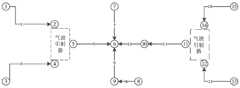
图4为包含气波引射器的集输管网示意图;4 is a schematic diagram of a gathering and transportation pipeline network comprising a gas wave ejector;
图5为包含气波引射器的集输管网计算方法流程示意图;5 is a schematic flowchart of a calculation method for a gathering and transportation pipeline network including a gas wave ejector;
图6为包含气波引射器的集输管网计算装置结构示意图;6 is a schematic structural diagram of a gathering and transportation pipeline network computing device comprising a gas wave ejector;
图7为包含气波引射器的集输管网计算方法一实施例示意图。FIG. 7 is a schematic diagram of an embodiment of a calculation method for a gathering and transportation pipeline network including a gas wave ejector.
具体实施方式Detailed ways
为使本发明实施例的目的、技术方案和优点更加清楚明白,下面结合实施例和附图,对本发明做进一步详细说明。在此,本发明的示意性实施例及其说明用于解释本发明,但并不作为对本发明的限定。In order to make the purposes, technical solutions and advantages of the embodiments of the present invention more clear, the present invention will be further described in detail below with reference to the embodiments and the accompanying drawings. Here, the exemplary embodiments of the present invention and their descriptions are used to explain the present invention, but not to limit the present invention.
请参考图4所示,本发明采取的技术方案是通过基于管网稳态方程,耦合气波引射器的特性方程,采用一种新的计算方法来求解管网的水力工艺参数,大致包括如下步骤:1、基于管网拓扑结构,选择节点法对管网稳态水力计算建立数学模型;2、用BWRS方程计算密度、压缩因子等物性参数;3、用等温输气管流量基本公式建立气相管道流量-压降规律;4、用气波引射器特性方程表示特殊节点进出口的流量-压降规律;5、采用牛顿-拉夫逊法对节点法数学模型进行求解,并且在迭代过程中引入阻尼系数来改善牛顿-拉夫逊法对初值比较敏感的问题,扩大该方法的收敛域,增加算法的稳定性。本发明主要应用于天然气集输管网设计、高低压气体混合输送等方向。具体请参考图5所示,上述方法具体包含:S101根据管网拓扑结构,通过节点法对管网稳态水力计算建立数学模型;S102根据所述数学模型和等温输气管流量基本公式建立气相管道流量与压降之间的关系方程;S103通过BWRS方程与管网信息,获得气相管道流量与压降之间的关系式的关系因子;S104根据所述关系因子和所述关系方程中,获得气相管道流量与压降之间的关系式;S105根据所述关系式和管网信息中输气管起点的气相管道流量或压降,获得气波引射器输入端的气相管道流量或压力;S106根据所述气波引射器输入端和管网信息中输气管终点的气相管道流量或压力,利用气波引射器输入端与输出端的函数关系,获得气波引射器输入端和输出端的气相管道流量或压力;在实际工作中,为提高结果的准确性,进一步通过对S102~S106进行数值方法迭代求解,以此利用往复计算提高最终结果的准确性,具体计算方式可参考后续的牛顿-拉夫逊法求解。Please refer to FIG. 4 , the technical solution adopted in the present invention is to solve the hydraulic process parameters of the pipe network by using a new calculation method based on the steady state equation of the pipe network and the characteristic equation of the coupled gas wave ejector, which roughly includes The following steps: 1. Based on the topological structure of the pipe network, select the node method to establish a mathematical model for the steady-state hydraulic calculation of the pipe network; 2. Use the BWRS equation to calculate the physical parameters such as density and compression factor; 3. Use the basic formula of the isothermal gas pipeline flow to establish the gas phase Pipeline flow-pressure drop law; 4. The flow-pressure drop law at the inlet and outlet of a special node is represented by the characteristic equation of the gas wave ejector; 5. The node method mathematical model is solved by the Newton-Raphson method, and in the iterative process A damping coefficient is introduced to improve the problem that the Newton-Raphson method is sensitive to the initial value, expand the convergence area of the method, and increase the stability of the algorithm. The invention is mainly applied to the design of natural gas gathering and transportation pipeline network, the mixed transportation of high and low pressure gas and the like. Please refer to Fig. 5 for details. The above method specifically includes: S101, according to the topological structure of the pipe network, establish a mathematical model for the steady-state hydraulic calculation of the pipe network through the node method; S102, according to the mathematical model and the basic formula of the isothermal gas pipeline flow, establish a gas-phase pipeline The relationship equation between the flow rate and the pressure drop; S103 obtains the relationship factor of the relationship between the gas phase pipeline flow rate and the pressure drop through the BWRS equation and the pipe network information; S104, according to the relationship factor and the relationship equation, obtain the gas phase The relationship between pipeline flow and pressure drop; S105 obtains the gas-phase pipeline flow or pressure at the input end of the gas wave ejector according to the relationship and the gas-phase pipeline flow or pressure drop at the starting point of the gas pipeline in the pipe network information; S106 Describe the flow rate or pressure of the gas-phase pipeline at the input end of the gas-wave ejector and the end of the gas pipeline in the pipe network information, and use the functional relationship between the input and output ends of the gas-wave ejector to obtain the gas-phase pipelines at the input and output ends of the gas-wave ejector. Flow or pressure; in actual work, in order to improve the accuracy of the results, iteratively solve S102~S106 by numerical method, so as to use the reciprocating calculation to improve the accuracy of the final result, the specific calculation method can refer to the follow-up Newton-Love Solving method.
在上述步骤S101中,针对管网拓扑结构进行矩阵表示,构建节点法管网稳态方程即数学模型具体如下所示:In the above step S101, a matrix representation is performed for the topology structure of the pipe network, and the steady state equation of the pipe network with the node method, that is, the mathematical model is constructed as follows:

上式中,Q=(Q1,Q2,…,Qm)T为管段的流量组成的向量,q=(q1,q2,…,qm)T为节点的流量组成的向量,A为关联矩阵;ΔP=(ΔP1,ΔP2,...,ΔPm)T为管段压降向量,B为环路矩阵;在上述实施例中,数学模型的主要目的是求出每个节点的流量q、压力P两个参数,其中Q=qQ-qZ,即进入管道的流量与流出管道的流量的差值,△P=PQ-PZ,即起点压力与终点压力的差值;多条管道相互连接形成管网,计算时管网结构是已知的,可根据管网结构写出矩阵A、B(此时也知道各个管道的连接关系及是否经过气波引射器)。公式1还需要建立Q和P之间的关系,经过管道就用公式3,经过气波引射器就用公式4。对于每个管网边界点(管网的起点和终点),q或者p有且只知道其中一个,但不能全是q或者全是p;此刻中间点不需要知道参数,可以算出来,以此达到对集输系统进行稳态分析的目的。In the above formula, Q=(Q1 ,Q2 ,...,Qm )T is the vector composed of the flow of the pipe section, q=(q1 ,q2 ,...,qm )T is the vector composed of the flow of the node, A is the correlation matrix; ΔP=(ΔP1 ,ΔP2 ,...,ΔPm )T is the pressure drop vector of the pipe section, and B is the loop matrix; in the above embodiment, the main purpose of the mathematical model is to obtain each There are two parameters of flow q and pressure P at the node, where Q=qQ -qZ , that is, the difference between the flow entering the pipeline and the flow flowing out of the pipeline, △P=PQ -PZ , which is the difference between the starting pressure and the ending pressure. The difference value; multiple pipes are connected to each other to form a pipe network. The pipe network structure is known during the calculation, and the matrix A and B can be written according to the pipe network structure (at this time, the connection relationship of each pipe and whether it is ejected by air waves are also known. device). Formula 1 also needs to establish the relationship between Q and P. Formula 3 is used when passing through the pipeline, and formula 4 is used when passing through the gas wave ejector. For each boundary point of the pipe network (the starting point and the end point of the pipe network), q or p has one and only one of them is known, but not all q or all p; at this moment, the intermediate point does not need to know the parameters, it can be calculated, so that To achieve the purpose of steady-state analysis of the gathering and transportation system.
在上述步骤S102中,所述气相管道流量与压降之间的关系方程具体可通过采用等温输气管的流量公式来构建,以此进行管网流量压降计算,具体构建的关系方程如下所示:In the above-mentioned step S102, the relationship equation between the gas phase pipeline flow rate and the pressure drop can be specifically constructed by adopting the flow rate formula of the isothermal gas transmission pipe, so as to calculate the flow pressure drop of the pipe network, and the specifically constructed relationship equation is as follows :

上式中,Q为输气管道在状况下的体积流量,Nm3/s;pQ为输气管起点压力,Pa;pZ为输气管终点压力,Pa;T为输气温度,K;T0为标准状况下的温度,K;D为输气管内径,m;p0为标准状况下的压力,Pa;λ为水力摩阻系数;Z为天然气在管道平均压力和温度下的压缩因子;Δ*为天然气的相对密度;Ra为空气的气体常数,kJ·(kg·K)-1;Δs为输气管终点与起点的高程差,m;L为输气管的长度,m;In the above formula, Q is the volume flow of the gas pipeline under conditions, Nm3 /s; pQ is the starting pressure of the gas pipeline, Pa; pZ is the end pressure of the gas pipeline, Pa; T is the gas temperature, K; T0 is the temperature under standard conditions, K; D is the inner diameter of the gas pipeline, m; p0 is the pressure under standard conditions, Pa; λ is the hydraulic friction coefficient; Z is the compression factor of natural gas under the average pressure and temperature of the pipeline; Δ* is the relative density of natural gas;Ra is the gas constant of air, kJ·(kg·K)-1 ; Δs is the elevation difference between the end point and the starting point of the gas pipeline, m; L is the length of the gas pipeline, m;
其中


在上述步骤S103和S105中,所述通过BWRS方程与管网信息,获得气相管道流量与压降之间的关系式的关系因子主要通过BWRS状态方程的11个参数以及上述C0,a和b的计算公式获得,其中,所述BWRS方程具体如下所示:In the above steps S103 and S105, the relationship factor of the relationship between the gas phase pipeline flow rate and the pressure drop is obtained through the BWRS equation and the pipe network information mainly through the 11 parameters of the BWRS state equation and the above C0 , a and b The calculation formula is obtained, wherein, the BWRS equation is specifically as follows:

上式中,P为系统的压力,kPa;T为系统的温度,K;ρ为气相或液相的摩尔密度,kmol/m3;R为气体常数,R=8.3143kJ·(kmol·K);A0,B0,C0,D0,E0,a,b,c,α,γ是BWRS状态方程的11个参数。对于某个纯组分i的各项参数均可由其纯组分的临界参数Tci,ρci和偏心因子wi求得。In the above formula, P is the pressure of the system, kPa; T is the temperature of the system, K; ρ is the molar density of the gas or liquid phase, kmol/m3 ; R is the gas constant, R=8.3143kJ·(kmol·K) ; A0 , B0 , C0 , D0 , E0 , a, b, c, α, γ are the 11 parameters of the BWRS state equation. The parameters for a certain pure componenti can be obtained from the critical parameters Tci , ρci and the eccentricity factor wi of the pure component.

上式中:mL为低压气体质量流量;mH为高压气体质量流量;


在上述实施例中,值得说明的是,所述输气管起点的气相管道流量或压力包含:高压井口起点的气相管道流量或压力,和低压井口起点的气相管道流量或压力;当所述高压井口起点的气相管道流量或压力、所述低压井口起点的气相管道流量或压力和所述管网信息中输气管终点三者中任意两点为气相管道流量时,剩余一点为气相管道压力;当所述高压井口起点的气相管道流量或压力、所述低压井口起点的气相管道流量或压力和所述管网信息中输气管终点三者中任意两点为气相管道压力时,剩余一点为气相管道流量。In the above embodiment, it is worth noting that the gas pipeline flow or pressure at the starting point of the gas pipeline includes: the gas pipeline flow or pressure at the starting point of the high-pressure wellhead, and the gas-phase pipeline flow or pressure at the starting point of the low-pressure wellhead; when the high-pressure wellhead When any two points of the gas pipeline flow or pressure at the starting point, the gas pipeline flow or pressure at the starting point of the low-pressure wellhead, and the end point of the gas pipeline in the pipe network information are the gas pipeline flow, the remaining point is the gas pipeline pressure; When any two points in the gas phase pipeline flow or pressure at the starting point of the high-pressure wellhead, the gas-phase pipeline flow or pressure at the starting point of the low-pressure wellhead, and the gas pipeline end point in the pipe network information are the gas-phase pipeline pressure, the remaining point is the gas-phase pipeline flow rate .
在上述步骤S106中,除了常规的计算方法之外,为快速计算结果,在本发明一优选的实施例中,通过上述步骤建立关系方程后,还可通过牛顿-拉夫逊法进行数值求解,具体方法如下:记Δx(k)=x(k+1)-x(k),给定初值x(0),得到改进牛顿-拉夫逊法迭代格式:In the above-mentioned step S106, in addition to the conventional calculation method, in order to quickly calculate the result, in a preferred embodiment of the present invention, after the relational equation is established through the above-mentioned steps, the Newton-Raphson method can also be used for numerical solution. The method is as follows: Denote Δx(k) = x(k+1) -x(k) , given the initial value x(0) , to obtain the improved Newton-Raphson method iteration format:

式中,η为阻尼系数。where η is the damping coefficient.
迭代终止标准取为
其中方程组DF(x(k))Δx(k)=-F(x(k))是线性的,采用高斯列主元消元法进行求解。The equation system DF(x(k) )Δx(k) =-F(x(k) ) is linear, and is solved by the Gaussian column pivoting method.
为更清楚的说明上述流程及计算方法,以下以具体实例,对上述计算流程做进一步说明:In order to illustrate the above process and calculation method more clearly, the following specific examples are used to further illustrate the above calculation process:
(1)读取管网基本数据,如管径、管长、节点高度等;(2)迭代次数设为k,给定管网稳态计算的边界条件(已知节点的压力或流量),并给未知的节点压力和流量赋予一个合理的初始值xk;亦即假设一个值,然后不断重新去算,直到最后符合条件;(3)根据管段两端压力及温度计算管段内气体的物性参数,如压缩因子、密度等(公式2);(4)根据求得的气体物性参数,利用公式3、公式4将所有管段的流量写成关于起点压力和终点压力的表达式并带入(公式1);(5)根据xk的值计算f(xk)的值及f(xk)的雅克比矩阵J(xk);(6)根据(公式5)计算Δxk及xk+1;(7)若Δxk≤ε则停止计算,并输出结果xk+1;(8)若Δxk>ε,则将xk+1的值赋给相应的节点压力或流量,并返回到步骤(3)进行第k+1次迭代计算。(1) Read the basic data of the pipe network, such as pipe diameter, pipe length, node height, etc.; (2) The number of iterations is set to k, and the boundary conditions for the steady-state calculation of the pipe network (the pressure or flow of the known nodes) are given, And give a reasonable initial value xk to the unknown nodal pressure and flow; that is to say, assume a value, and then recalculate continuously until the conditions are finally met; (3) Calculate the physical properties of the gas in the pipe section according to the pressure and temperature at both ends of the pipe section Parameters, such as compression factor, density, etc. (Formula 2); (4) According to the obtained gas physical property parameters, use Formula 3 and Formula 4 to write the flow rate of all pipe sections into expressions about the starting pressure and the ending pressure and bring it into (Formula 4) 1); (5) Calculate the value of f(xk ) and the Jacobian matrix J(xk ) of f(xk ) according to the value of xk ; (6) Calculate Δxk and xk+ according to (Formula 5)1 ; (7) If Δxk ≤ε, stop the calculation and output the result xk+1 ; (8) If Δxk >ε, assign the value of xk+1 to the corresponding node pressure or flow, and return Go to step (3) to perform the k+1th iterative calculation.
基于上述流程,请参考图7所示,该枝状管网由15个节点和10条管段组成,其中节点1,3,7,8,9,10,13,15为气体流入点,节点6为气体流出点,节点2,4,5,11,12,14为气波引射器端口。气体组分为甲烷85%,二氧化碳14%,氮气1%,温度为30℃,气体粘度为1.10125×10⁻⁵N·s/m2。气波引射器ξ抽射比0.4,η等熵效率0.6。给定终点6的压力及其他起始点的流量,需要求出终点6的流量及其他节点的流量、压力;其中气相枝状管网基本数据如下表1所示:Based on the above process, please refer to Figure 7, the branch pipe network consists of 15 nodes and 10 pipe segments, of which
表1Table 1

基于上述待求问题,本发明在此采用迭代求解,现结合具体实施例说明程序中某些参数的取值和计算过程:Based on the above-mentioned problem to be solved, the present invention adopts iterative solution here, and now in conjunction with specific embodiments, the value and calculation process of some parameters in the program are described:
1、首先根据管网结构写出关联矩阵A、环路矩阵B、管段流量向量Q、节点流量向量q、管段压降向量ΔP,构建节点法管网稳态方程:1. First, write the correlation matrix A, loop matrix B, pipe flow vector Q, node flow vector q, and pipe pressure drop vector ΔP according to the pipe network structure, and construct the steady state equation of the nodal method:

B=0;b = 0;
Q=(Q1,Q3,Q5,Q7,Q8,Q9,Q10,Q11,Q13,Q15)T;Q=(Q1 , Q3 , Q5 , Q7 , Q8 , Q9 , Q10 , Q11 , Q13 , Q15 )T ;
q=(20,q2,8.162,q4,q5,q6,15,15,15,15,q11,q12,6.122,q14,15)T;q=(20,q2 ,8.162,q4 ,q5 ,q6 ,15,15,15,15,q11 ,q12 ,6.122,q14 ,15)T ;
ΔP=(ΔP1,ΔP3,ΔP5,ΔP7,ΔP8,ΔP9,ΔP10,ΔP11,ΔP13,ΔP15)T;ΔP=(ΔP1 , ΔP3 , ΔP5 , ΔP7 , ΔP8 , ΔP9 , ΔP10 , ΔP11 , ΔP13 , ΔP15 )T ;

2、利用等温输气管流量基本公式建立气相管道流量-压降规律:2. Use the basic formula of isothermal gas pipeline flow to establish the gas-phase pipeline flow-pressure drop law:

其中


常数C0的数值取决于式中各参数所选择的单位。本文公式中所有参数都采用我国的法定单位,T0=293K,p0=101325Pa,Ra=287.1kJ·(kg·K)-1,则有:C0=0.03848m2·s·K1/2·kg-1。摩阻系数λ本文初始值取为0.01。管径D、管道长度L采用表1的对应值,温度T=303K(30℃)。The value of the constant C0 depends on the unit selected for each parameter in the formula. All the parameters in the formulas in this paper adopt the legal unit of our country, T0 =293K, p0 =101325Pa, Ra =287.1kJ·(kg·K)-1 , then: C0 =0.03848m2 ·s·K1 /2 ·kg-1 . The initial value of friction coefficient λ is taken as 0.01 in this paper. The pipe diameter D and the pipe length L adopt the corresponding values in Table 1, and the temperature T=303K (30°C).
3、结合气体组分为甲烷85%,二氧化碳14%,氮气1%,温度为30℃,气体粘度为1.10125×10⁻⁵N·s/m2,利用BWRS方程求得压缩因子和相对密度等关系因子。3. The combined gas components are 85% methane, 14% carbon dioxide, 1% nitrogen, the temperature is 30°C, and the gas viscosity is 1.10125×10⁻⁵ N·s/m2 , and the compression factor and relative density are obtained by using the BWRS equation. relationship factor.
4、气波引射器特性方程:4. The characteristic equation of the air wave ejector:

抽射比ξ=0.4,等熵效率η=0.6,三个端口的温度为T=303K(30℃),绝热指数k=1.4。The evacuated ratio ξ=0.4, the isentropic efficiency η=0.6, the temperature of the three ports was T=303K (30°C), and the adiabatic index k=1.4.
5、编程迭代求解,采用改进的牛顿拉夫逊方法:5. Programming iterative solution, using the improved Newton-Raphson method:

式中,η为阻尼系数。where η is the damping coefficient.
迭代终止标准取为
η阻尼系数采用试算法,即:首先取阻尼系数为1进行计算,若收敛则停止计算;若不收敛则阻尼系数按某一值递减(本文取为0.1),再次进行计算,直到阻尼系数取到设定的最小值为止。本文迭代次数k为500次,误差精度ε为1E-10,可根据实际需要进行调整。The η damping coefficient adopts the trial algorithm, that is: first, take the damping coefficient as 1 for calculation, and stop the calculation if it converges; to the set minimum value. The number of iterations k in this paper is 500 times, and the error accuracy ε is 1E-10, which can be adjusted according to actual needs.
6、经过以上步骤,结果如下表2所示:6. After the above steps, the results are shown in Table 2 below:
表2Table 2


以此获得未知参数。In this way, the unknown parameters are obtained.
本发明还提供一种包含气波引射器的集输管网计算装置,具体请参考图6所示,所述计算装置包含:管网水力模块、物性计算模块和压力耦合模块;所述管网水力模块用于根据管网拓扑结构,通过节点法对管网稳态水力计算建立数学模型;所述物性计算模块用于通过BWRS方程与管网信息,获得气相管道流量与压降之间的关系式的关系因子;所述压力耦合模块用于根据所述数学模型和等温输气管流量基本公式建立气相管道流量与压降之间的关系方程;并根据所述关系因子获得气相管道流量与压降之间的关系式;以及根据所述关系式和管网信息中输气管起点的气相管道流量或压力,获得气波引射器输入端的气相管道流量或压力;根据所述气波引射器输入端和管网信息中输气管终点的气相管道流量或压力,利用气波引射器输入端与输出端的函数关系,获得气波引射器输入端和输出端的气相管道流量或压力。The present invention also provides a computing device for a gathering and transportation pipeline network including a gas wave ejector. Please refer to FIG. 6 for details. The computing device includes: a pipeline network hydraulic module, a physical property calculation module and a pressure coupling module; The network hydraulic module is used to establish a mathematical model for the steady-state hydraulic calculation of the pipe network through the node method according to the topology of the pipe network; the physical property calculation module is used to obtain the relationship between the gas phase pipeline flow and pressure drop through the BWRS equation and the pipe network information. The relationship factor of the relational expression; the pressure coupling module is used to establish the relationship equation between the gas phase pipeline flow rate and the pressure drop according to the mathematical model and the basic formula of the isothermal gas pipeline flow rate; and obtain the gas phase pipeline flow rate and pressure drop according to the relationship factor. and according to the relational expression and the gas-phase pipeline flow or pressure at the starting point of the gas pipeline in the pipe network information, obtain the gas-phase pipeline flow or pressure at the input end of the gas-wave ejector; according to the gas-wave ejector The gas-phase pipeline flow or pressure at the end of the gas pipeline in the input and pipe network information, and the gas-phase pipeline flow or pressure at the input and output of the gas-wave ejector is obtained by using the functional relationship between the input and output of the gas-wave ejector.
在上述实施例中,所述计算装置还包含数据采集模块,所述数据采集模块用于采集管网信息,所述管网信息除了包含管径、管长、节点高度等,还包含高压井口起点的气相管道流量或压力,输气管终点的气相管道流量或压降和低压井口起点的气相管道流量或压力;其中,当所述高压井口起点的气相管道流量或压力、所述低压井口起点的气相管道流量或压力和所述管网信息中输气管终点三者中任意两点为气相管道流量时,剩余一点为气相管道压力;当所述高压井口起点的气相管道流量或压力、所述低压井口起点的气相管道流量或压力和所述管网信息中输气管终点三者中任意两点为气相管道压力时,剩余一点为气相管道流量。In the above embodiment, the computing device further includes a data acquisition module, and the data acquisition module is used to collect pipe network information. The pipe network information includes not only the pipe diameter, pipe length, node height, etc., but also the starting point of the high-pressure wellhead. The flow rate or pressure of the gas phase pipeline, the flow rate or pressure drop of the gas pipeline at the end of the gas pipeline, and the flow rate or pressure of the gas phase pipeline at the starting point of the low pressure wellhead; wherein, when the flow rate or pressure of the gas phase pipeline at the starting point of the high pressure wellhead, the When any two points in the pipeline flow or pressure and the end point of the gas pipeline in the pipeline network information are the gas pipeline flow, the remaining point is the gas pipeline pressure; when the gas pipeline flow or pressure at the starting point of the high-pressure wellhead, the low-pressure wellhead When any two points of the gas pipeline flow or pressure at the starting point and the end point of the gas pipeline in the pipe network information are the gas pipeline pressure, the remaining point is the gas pipeline flow.
在上述实施例中,所述压力耦合模块还包含气波引射器计算单元,所述气波引射器计算单元用于根据以下公式计算气波引射器输入端和输出端的气相管道流量或压力;In the above embodiment, the pressure coupling module further includes a gas wave ejector calculation unit, and the gas wave ejector calculation unit is configured to calculate the gas-phase pipeline flow rate at the input end and the output end of the gas wave ejector according to the following formula or pressure;

上式中:mL为低压气体质量流量;mH为高压气体质量流量;


以上所述的具体实施例,对本发明的目的、技术方案和有益效果进行了进一步详细说明,所应理解的是,以上所述仅为本发明的具体实施例而已,并不用于限定本发明的保护范围,凡在本发明的精神和原则之内,所做的任何修改、等同替换、改进等,均应包含在本发明的保护范围之内。The specific embodiments described above further describe the purpose, technical solutions and beneficial effects of the present invention in detail. It should be understood that the above-mentioned specific embodiments are only specific embodiments of the present invention, and are not intended to limit the scope of the present invention. Any modification, equivalent replacement, improvement, etc. made within the spirit and principle of the present invention shall be included within the protection scope of the present invention.
Claims (6)
Translated fromChinese


Priority Applications (1)
| Application Number | Priority Date | Filing Date | Title |
|---|---|---|---|
| CN201710384301.2ACN107066767B (en) | 2017-05-26 | 2017-05-26 | A calculation method and device for a gathering and transportation pipeline network including a gas wave ejector |
Applications Claiming Priority (1)
| Application Number | Priority Date | Filing Date | Title |
|---|---|---|---|
| CN201710384301.2ACN107066767B (en) | 2017-05-26 | 2017-05-26 | A calculation method and device for a gathering and transportation pipeline network including a gas wave ejector |
Publications (2)
| Publication Number | Publication Date |
|---|---|
| CN107066767A CN107066767A (en) | 2017-08-18 |
| CN107066767Btrue CN107066767B (en) | 2020-07-28 |
Family
ID=59609895
Family Applications (1)
| Application Number | Title | Priority Date | Filing Date |
|---|---|---|---|
| CN201710384301.2AActiveCN107066767B (en) | 2017-05-26 | 2017-05-26 | A calculation method and device for a gathering and transportation pipeline network including a gas wave ejector |
Country Status (1)
| Country | Link |
|---|---|
| CN (1) | CN107066767B (en) |
Families Citing this family (4)
| Publication number | Priority date | Publication date | Assignee | Title |
|---|---|---|---|---|
| CN107545109B (en)* | 2017-08-31 | 2020-06-05 | 中国石油大学(北京) | Optimization method of coal bed gas field acquisition system |
| CN110705766B (en)* | 2019-09-25 | 2023-04-07 | 中国石油大学(北京) | Optimization method and device for gas field gathering and transportation system |
| CN114186169B (en)* | 2021-11-26 | 2023-12-12 | 西南石油大学 | Natural gas gathering and transportation pipeline transportation efficiency evaluation method |
| CN115130260B (en)* | 2022-07-13 | 2025-09-23 | 中国石油大学(北京) | A single-phase flow-multiphase flow coupling calculation method and device for gas field gathering and transportation pipeline network |
Citations (6)
| Publication number | Priority date | Publication date | Assignee | Title |
|---|---|---|---|---|
| UA27730U (en)* | 2007-07-10 | 2007-11-12 | State Makiivka Scient Res I Fo | Appliance for preventing thermal injury of miners |
| CN101936567A (en)* | 2010-05-20 | 2011-01-05 | 王建新 | Heat supply method and heat supply unit taking steam as heating medium |
| CN102864257A (en)* | 2012-09-28 | 2013-01-09 | 中冶南方工程技术有限公司 | Pressure-equalizing and bleeding method for injecting furnace roof tank coal gas by using high-pressure gas |
| CN204112415U (en)* | 2014-10-20 | 2015-01-21 | 湖北中天鸿源房地产开发有限责任公司 | In highrise building without negative pressure energy-saving supply equipment |
| CN104573143A (en)* | 2013-10-12 | 2015-04-29 | 苏州热工研究院有限公司 | Pipe network simulation system and hydraulic calculation method |
| RU2015109408A (en)* | 2015-03-17 | 2016-10-10 | Федеральное государственное бюджетное образовательное учреждение высшего профессионального образования "Ульяновский государственный технический университет" | Heating cogeneration plant |
- 2017
- 2017-05-26CNCN201710384301.2Apatent/CN107066767B/enactiveActive
Patent Citations (6)
| Publication number | Priority date | Publication date | Assignee | Title |
|---|---|---|---|---|
| UA27730U (en)* | 2007-07-10 | 2007-11-12 | State Makiivka Scient Res I Fo | Appliance for preventing thermal injury of miners |
| CN101936567A (en)* | 2010-05-20 | 2011-01-05 | 王建新 | Heat supply method and heat supply unit taking steam as heating medium |
| CN102864257A (en)* | 2012-09-28 | 2013-01-09 | 中冶南方工程技术有限公司 | Pressure-equalizing and bleeding method for injecting furnace roof tank coal gas by using high-pressure gas |
| CN104573143A (en)* | 2013-10-12 | 2015-04-29 | 苏州热工研究院有限公司 | Pipe network simulation system and hydraulic calculation method |
| CN204112415U (en)* | 2014-10-20 | 2015-01-21 | 湖北中天鸿源房地产开发有限责任公司 | In highrise building without negative pressure energy-saving supply equipment |
| RU2015109408A (en)* | 2015-03-17 | 2016-10-10 | Федеральное государственное бюджетное образовательное учреждение высшего профессионального образования "Ульяновский государственный технический университет" | Heating cogeneration plant |
Non-Patent Citations (2)
| Title |
|---|
| 《气波引射器的参数优化及实验研究》;魏丽;《中国优秀硕士学位论文全文数据库 工程科技Ⅰ辑》;20121015;第B019-147页* |
| 《结构和操作参数对气波引射器性能的影响》;朱立志;《中国优秀硕士学位论文全文数据库 工程科技Ⅰ辑》;20130815;第B019-47页* |
Also Published As
| Publication number | Publication date |
|---|---|
| CN107066767A (en) | 2017-08-18 |
Similar Documents
| Publication | Publication Date | Title |
|---|---|---|
| CN107145696B (en) | A simulation method for the above-ground and underground coupling solution of coalbed methane | |
| CN107066767B (en) | A calculation method and device for a gathering and transportation pipeline network including a gas wave ejector | |
| CN106127599B (en) | A point method is split for gas well yield of the tight gas reservoir under gas gathering station production model | |
| Cheng et al. | A rigorous compressible streamline formulation for two-and three-phase black-oil simulation | |
| CN111353205B (en) | Method for calculating formation pressure and dynamic productivity of water-producing gas well of tight gas reservoir | |
| CN109740242B (en) | Unified Energy Flow Calculation Method for Electric-Gas Integrated Energy System Considering Natural Gas Thermal Process | |
| CN112069692A (en) | Optimization solving method for natural gas pipe network transmission difference calculation | |
| CN104989385B (en) | The HTHP oil gas straight well perforating parameter optimization method calculated based on skin factor | |
| CN107575214B (en) | Prediction method of temperature and pressure in well bore for injection-production process | |
| CN116894572B (en) | Reasonable production allocation method for ultra-deep well considering sand production after rock collapse | |
| Gu et al. | Computationally efficient simulation of non-isothermal two-phase flow during well construction using a new reduced drift-flux model | |
| CN116738871A (en) | Shale gas gathering and transportation system pressurizing allocation optimization method considering time variability | |
| CN110796295B (en) | An optimization method for energy internet gas network transmission | |
| Jiao et al. | Efficiency and pressure recovery in hydraulic jet pumping of two-phase gas/liquid mixtures | |
| Hong et al. | An improved hydraulic model of gathering pipeline network integrating pressure-exchange ejector | |
| Klins et al. | An improved method to predict future IPR curves | |
| CN104729970B (en) | Measurement Method of Relative Permeability Curve of Foam Drive Fluid | |
| Zhou et al. | Coalbed methane production system simulation and deliverability forecasting: coupled surface network/wellbore/reservoir calculation | |
| CN111663916A (en) | Underground oil pipe leakage simulation system | |
| CN118690523A (en) | A method for evaluating the depth of liquid accumulation in a gas well, storage medium and device | |
| Shields et al. | Integrated production modelling for CSG production forecasting | |
| Merrill et al. | Three-Phase Numerical Solution for Jet Pumps Applied to a Large Oilfield | |
| Berard et al. | An improved gas transmission system simulator | |
| Castrup et al. | Tapered-Bean Steam Chokes Revisited | |
| CN118673839A (en) | Simulation system implementation method of gas pipe network |
Legal Events
| Date | Code | Title | Description |
|---|---|---|---|
| PB01 | Publication | ||
| PB01 | Publication | ||
| SE01 | Entry into force of request for substantive examination | ||
| SE01 | Entry into force of request for substantive examination | ||
| GR01 | Patent grant | ||
| GR01 | Patent grant |