CN107003124B - Drawer Vision System - Google Patents
Drawer Vision SystemDownload PDFInfo
- Publication number
- CN107003124B CN107003124BCN201580039713.1ACN201580039713ACN107003124BCN 107003124 BCN107003124 BCN 107003124BCN 201580039713 ACN201580039713 ACN 201580039713ACN 107003124 BCN107003124 BCN 107003124B
- Authority
- CN
- China
- Prior art keywords
- image
- tube
- tray
- images
- sample tube
- Prior art date
- Legal status (The legal status is an assumption and is not a legal conclusion. Google has not performed a legal analysis and makes no representation as to the accuracy of the status listed.)
- Active
Links
Images


Classifications
- G—PHYSICS
- G06—COMPUTING OR CALCULATING; COUNTING
- G06T—IMAGE DATA PROCESSING OR GENERATION, IN GENERAL
- G06T7/00—Image analysis
- G06T7/0002—Inspection of images, e.g. flaw detection
- G06T7/0012—Biomedical image inspection
- G—PHYSICS
- G01—MEASURING; TESTING
- G01C—MEASURING DISTANCES, LEVELS OR BEARINGS; SURVEYING; NAVIGATION; GYROSCOPIC INSTRUMENTS; PHOTOGRAMMETRY OR VIDEOGRAMMETRY
- G01C11/00—Photogrammetry or videogrammetry, e.g. stereogrammetry; Photographic surveying
- G01C11/04—Interpretation of pictures
- G01C11/06—Interpretation of pictures by comparison of two or more pictures of the same area
- G—PHYSICS
- G01—MEASURING; TESTING
- G01N—INVESTIGATING OR ANALYSING MATERIALS BY DETERMINING THEIR CHEMICAL OR PHYSICAL PROPERTIES
- G01N21/00—Investigating or analysing materials by the use of optical means, i.e. using sub-millimetre waves, infrared, visible or ultraviolet light
- G01N21/84—Systems specially adapted for particular applications
- G01N21/88—Investigating the presence of flaws or contamination
- G01N21/95—Investigating the presence of flaws or contamination characterised by the material or shape of the object to be examined
- G01N21/952—Inspecting the exterior surface of cylindrical bodies or wires
- G—PHYSICS
- G01—MEASURING; TESTING
- G01N—INVESTIGATING OR ANALYSING MATERIALS BY DETERMINING THEIR CHEMICAL OR PHYSICAL PROPERTIES
- G01N35/00—Automatic analysis not limited to methods or materials provided for in any single one of groups G01N1/00 - G01N33/00; Handling materials therefor
- G01N35/00584—Control arrangements for automatic analysers
- G01N35/00722—Communications; Identification
- G01N35/00732—Identification of carriers, materials or components in automatic analysers
- G—PHYSICS
- G05—CONTROLLING; REGULATING
- G05B—CONTROL OR REGULATING SYSTEMS IN GENERAL; FUNCTIONAL ELEMENTS OF SUCH SYSTEMS; MONITORING OR TESTING ARRANGEMENTS FOR SUCH SYSTEMS OR ELEMENTS
- G05B21/00—Systems involving sampling of the variable controlled
- G—PHYSICS
- G05—CONTROLLING; REGULATING
- G05B—CONTROL OR REGULATING SYSTEMS IN GENERAL; FUNCTIONAL ELEMENTS OF SUCH SYSTEMS; MONITORING OR TESTING ARRANGEMENTS FOR SUCH SYSTEMS OR ELEMENTS
- G05B21/00—Systems involving sampling of the variable controlled
- G05B21/02—Systems involving sampling of the variable controlled electric
- G—PHYSICS
- G06—COMPUTING OR CALCULATING; COUNTING
- G06F—ELECTRIC DIGITAL DATA PROCESSING
- G06F18/00—Pattern recognition
- G06F18/20—Analysing
- G06F18/24—Classification techniques
- G06F18/243—Classification techniques relating to the number of classes
- G06F18/24323—Tree-organised classifiers
- G—PHYSICS
- G06—COMPUTING OR CALCULATING; COUNTING
- G06T—IMAGE DATA PROCESSING OR GENERATION, IN GENERAL
- G06T7/00—Image analysis
- G06T7/0002—Inspection of images, e.g. flaw detection
- G06T7/0004—Industrial image inspection
- G06T7/0008—Industrial image inspection checking presence/absence
- G—PHYSICS
- G06—COMPUTING OR CALCULATING; COUNTING
- G06T—IMAGE DATA PROCESSING OR GENERATION, IN GENERAL
- G06T7/00—Image analysis
- G06T7/80—Analysis of captured images to determine intrinsic or extrinsic camera parameters, i.e. camera calibration
- G—PHYSICS
- G06—COMPUTING OR CALCULATING; COUNTING
- G06V—IMAGE OR VIDEO RECOGNITION OR UNDERSTANDING
- G06V10/00—Arrangements for image or video recognition or understanding
- G06V10/70—Arrangements for image or video recognition or understanding using pattern recognition or machine learning
- G06V10/764—Arrangements for image or video recognition or understanding using pattern recognition or machine learning using classification, e.g. of video objects
- G—PHYSICS
- G06—COMPUTING OR CALCULATING; COUNTING
- G06V—IMAGE OR VIDEO RECOGNITION OR UNDERSTANDING
- G06V20/00—Scenes; Scene-specific elements
- G06V20/50—Context or environment of the image
- G06V20/52—Surveillance or monitoring of activities, e.g. for recognising suspicious objects
- G—PHYSICS
- G01—MEASURING; TESTING
- G01N—INVESTIGATING OR ANALYSING MATERIALS BY DETERMINING THEIR CHEMICAL OR PHYSICAL PROPERTIES
- G01N35/00—Automatic analysis not limited to methods or materials provided for in any single one of groups G01N1/00 - G01N33/00; Handling materials therefor
- G01N35/02—Automatic analysis not limited to methods or materials provided for in any single one of groups G01N1/00 - G01N33/00; Handling materials therefor using a plurality of sample containers moved by a conveyor system past one or more treatment or analysis stations
- G01N35/04—Details of the conveyor system
- G01N2035/0401—Sample carriers, cuvettes or reaction vessels
- G01N2035/0418—Plate elements with several rows of samples
- G—PHYSICS
- G01—MEASURING; TESTING
- G01N—INVESTIGATING OR ANALYSING MATERIALS BY DETERMINING THEIR CHEMICAL OR PHYSICAL PROPERTIES
- G01N35/00—Automatic analysis not limited to methods or materials provided for in any single one of groups G01N1/00 - G01N33/00; Handling materials therefor
- G01N35/02—Automatic analysis not limited to methods or materials provided for in any single one of groups G01N1/00 - G01N33/00; Handling materials therefor using a plurality of sample containers moved by a conveyor system past one or more treatment or analysis stations
- G01N35/04—Details of the conveyor system
- G01N2035/0496—Other details
- G01N2035/0498—Drawers used as storage or dispensing means for vessels or cuvettes
- G—PHYSICS
- G06—COMPUTING OR CALCULATING; COUNTING
- G06T—IMAGE DATA PROCESSING OR GENERATION, IN GENERAL
- G06T2207/00—Indexing scheme for image analysis or image enhancement
- G06T2207/20—Special algorithmic details
- G06T2207/20081—Training; Learning
- G—PHYSICS
- G06—COMPUTING OR CALCULATING; COUNTING
- G06T—IMAGE DATA PROCESSING OR GENERATION, IN GENERAL
- G06T2207/00—Indexing scheme for image analysis or image enhancement
- G06T2207/30—Subject of image; Context of image processing
- G06T2207/30004—Biomedical image processing
- G06T2207/30024—Cell structures in vitro; Tissue sections in vitro
- G—PHYSICS
- G06—COMPUTING OR CALCULATING; COUNTING
- G06T—IMAGE DATA PROCESSING OR GENERATION, IN GENERAL
- G06T2207/00—Indexing scheme for image analysis or image enhancement
- G06T2207/30—Subject of image; Context of image processing
- G06T2207/30004—Biomedical image processing
- G06T2207/30072—Microarray; Biochip, DNA array; Well plate
- G—PHYSICS
- G06—COMPUTING OR CALCULATING; COUNTING
- G06T—IMAGE DATA PROCESSING OR GENERATION, IN GENERAL
- G06T2207/00—Indexing scheme for image analysis or image enhancement
- G06T2207/30—Subject of image; Context of image processing
- G06T2207/30204—Marker
Landscapes
- Engineering & Computer Science (AREA)
- Physics & Mathematics (AREA)
- General Physics & Mathematics (AREA)
- Theoretical Computer Science (AREA)
- Computer Vision & Pattern Recognition (AREA)
- Health & Medical Sciences (AREA)
- General Health & Medical Sciences (AREA)
- Multimedia (AREA)
- Life Sciences & Earth Sciences (AREA)
- Quality & Reliability (AREA)
- Pathology (AREA)
- Immunology (AREA)
- Biochemistry (AREA)
- Medical Informatics (AREA)
- Analytical Chemistry (AREA)
- Chemical & Material Sciences (AREA)
- Artificial Intelligence (AREA)
- Data Mining & Analysis (AREA)
- Evolutionary Computation (AREA)
- Automation & Control Theory (AREA)
- Radiology & Medical Imaging (AREA)
- Nuclear Medicine, Radiotherapy & Molecular Imaging (AREA)
- Radar, Positioning & Navigation (AREA)
- Remote Sensing (AREA)
- Computing Systems (AREA)
- General Engineering & Computer Science (AREA)
- Evolutionary Biology (AREA)
- Bioinformatics & Computational Biology (AREA)
- Bioinformatics & Cheminformatics (AREA)
- Software Systems (AREA)
- Databases & Information Systems (AREA)
- Automatic Analysis And Handling Materials Therefor (AREA)
Abstract
Description
Translated fromChinese本申请要求2014年6月10日提交的美国临时申请序列号62/010,370的优先权,其通过引用以其整体被并入在本文中。This application claims priority to US Provisional Application Serial No. 62/010,370, filed June 10, 2014, which is incorporated herein by reference in its entirety.
技术领域technical field
本发明一般地涉及表征被包含在试管(tube)托盘中的试管,并且更特别地涉及训练和校准用于捕获试管托盘的图像的系统以确定被保持在托盘内的试管的特性。The present invention relates generally to characterizing test tubes contained in tube trays, and more particularly to training and calibrating systems for capturing images of test tube trays to determine characteristics of tubes held within the tray.
背景技术Background technique
体外诊断(IVD)允许实验室基于对病人流体样品执行的化验来辅助疾病的诊断。IVD包括可以通过分析从病人的体液或脓肿取得的液体样品而执行的与病人诊断和治疗相关的各种类型的分析测试和化验。典型地用包含病人样品的试管或药瓶已经被加载到其中的自动化临床化学分析仪(分析仪)来实施这些化验。由于在现代IVD实验室中需要的各种化验,以及操作实验室所必需的大量测试,常常在单个实验室中采用多个分析仪。在分析仪之间和之中,还可以使用自动化系统。可以将样品从医生的办公室运输到实验室、存储在实验室中、放置到自动化系统或分析仪中以及存储用于随后的测试。In vitro diagnostics (IVD) allow laboratories to aid in the diagnosis of disease based on assays performed on fluid samples from patients. IVD includes various types of analytical tests and assays related to patient diagnosis and treatment that can be performed by analyzing fluid samples taken from the patient's bodily fluids or abscesses. These assays are typically performed with automated clinical chemistry analyzers (analyzers) into which test tubes or vials containing patient samples have been loaded. Due to the variety of assays required in modern IVD laboratories, and the large number of tests necessary to operate the laboratory, multiple analyzers are often employed in a single laboratory. Between and among analyzers, automated systems can also be used. The sample can be transported from the doctor's office to the laboratory, stored in the laboratory, placed into an automated system or analyzer, and stored for subsequent testing.
典型地使用托盘来完成分析仪之间的存储和运输。托盘典型地是被存储在试管中的若干病人样品的阵列。这些托盘常常是可堆叠的并且促进多个样品从实验室的一部分到另一部分的容易承载。例如,实验室可以从医院或诊所接收用于测试的病人样品的托盘。病人样品的该托盘可以被存储在实验室的致冷机中。病人样品的托盘还可以被存储在抽屉(drawer)中。在一些自动化系统中,分析仪可以接受病人样品的托盘并且相应地对样品进行处理,而一些分析仪可以要求由操作者将样品从托盘移除并且在进一步地处理之前将其放置到承载器(诸如圆盘)中。托盘一般是允许承载样品并且在某些情况下允许以有序关系布置样品的被动设备。Storage and transport between analyzers is typically accomplished using pallets. A tray is typically an array of several patient samples stored in test tubes. These trays are often stackable and facilitate easy carrying of multiple samples from one part of the laboratory to another. For example, a laboratory may receive trays of patient samples for testing from a hospital or clinic. This tray of patient samples can be stored in a laboratory refrigerator. Trays of patient samples can also be stored in drawers. In some automated systems, the analyzer may accept a tray of patient samples and process the sample accordingly, while some analyzers may require the operator to remove the sample from the tray and place it on a carrier ( such as a disc). Trays are generally passive devices that allow samples to be carried and, in some cases, arranged in an ordered relationship.
一般地,不知道关于被存储在托盘中的样品试管的信息直到操作者或样品处理机构与每个试管交互。例如,样品处理机器人手臂可以拾取试管、将其从托盘移除并且将其放置到承载器中。承载器然后可以行进到开瓶器站以移除任何可能的盖并且经过条形码读取器使得试管的侧面上的条形码可以被读取以揭露试管的内含物(content)。在许多现有技术的样品处理机构中,不知道试管的身份直到将试管从托盘移除之后。以该方式,托盘中的所有试管将常常被以相同方式处理直到将试管放置到自动化系统中的承载器上之后。Typically, no information is known about the sample tubes stored in the tray until the operator or sample processing facility interacts with each tube. For example, a sample processing robotic arm can pick up a test tube, remove it from the tray, and place it into a carrier. The carrier can then travel to the corkscrew station to remove any possible caps and pass the barcode reader so that the barcode on the side of the tube can be read to reveal the contents of the tube. In many prior art sample processing mechanisms, the identity of the test tube is not known until after the test tube is removed from the tray. In this way, all the tubes in the tray will often be handled in the same way until after the tubes are placed on the carrier in the automated system.
一些系统允许操作者将托盘插入到抽屉中并且自动地旋转试管以辅助稍后的评估和标识。然而,此类系统仍依赖于常规的自动化系统来将样品试管从托盘移动到条形码读取站并且执行很少的或不执行样品试管的表征直到将试管从试管托盘移除之后。这可以导致对所使用的各种试管的实际约束,因为样品处理机(handler)不能计及高度、宽度、形状方面的极大程度的变化,以及是盖还是管顶杯(tube top cup)被放置在试管上。Some systems allow the operator to insert the tray into the drawer and automatically rotate the tube to aid in later evaluation and identification. However, such systems still rely on conventional automated systems to move sample tubes from the tray to the barcode reading station and perform little or no characterization of the sample tubes until after the tubes are removed from the tube tray. This can lead to practical constraints on the variety of tubes used, as the sample handler cannot account for extreme variations in height, width, shape, and whether the lid or tube top cup is placed on the test tube.
相应地,大部分现有技术的试管托盘抽屉和工作流程缺少智能系统以在试管托盘被放置到仪器中时自动地表征其中的试管,代替依赖于一旦它们被从试管托盘移除就对试管进行的后加载处理或工作流程中的更多手动表征。Accordingly, most prior art tube tray drawers and workflows lack an intelligent system to automatically characterize the tubes in a tube tray as it is placed into the instrument, instead relying on the ability to process tubes once they are removed from the tube tray. post-load processing or more manual characterization in the workflow.
发明内容SUMMARY OF THE INVENTION
期望的是确定与以下有关的各种信息片段:托盘、试管和试管在托盘内的位置,诸如例如包含试管的试管狭槽;试管的中心点、直径和高度;托盘在抽屉内的方位;试管被覆盖有盖还是管顶杯。期望的是在没有昂贵装备的情况下且在没有处理或触摸试管的情况下快速地获得这些和其他信息片段。相应地,进一步期望的是具有用于由可以实现这些上面的目标的抽屉视觉系统(DVS)使用的相机和图像处理的高效训练和校准方案。It is desirable to determine various pieces of information related to: trays, tubes and position of tubes within the tray, such as, for example, the tube slots containing the tubes; the centre point, diameter and height of the tubes; the orientation of the tray within the drawer; the tubes Is covered with a lid or a tube top cup. It is desirable to obtain these and other pieces of information quickly without expensive equipment and without handling or touching the test tube. Accordingly, it is further desirable to have efficient training and calibration schemes for cameras and image processing used by drawer vision systems (DVS) that can achieve these above goals.
本发明的实施例通过经由捕获托盘的图像和相关的校准和训练方案而提供对试管托盘的表征来解决上面的需要。Embodiments of the present invention address the above needs by providing characterization of test tube trays via capturing images of the tray and associated calibration and training protocols.
根据实施例,一种用于检测样品试管的性质的方法,包括如下步骤:从至少一个相机接收托盘的一系列图像;从每个图像提取多个图像块;以及使用处理器根据所述多个图像块的第一子集自动地确定多个狭槽中的每个是否包含样品试管,其中每个块与所述托盘中的多个狭槽中的一个对应。针对包含样品试管的那些多个狭槽,所述处理器根据所述多个图像块的第二子集自动地确定每个样品试管是否具有盖,其中每个块与所述样品试管的顶部对应。针对不具有盖的那些试管,所述处理器根据所述多个图像块的所述第二子集自动地确定每个样品试管具有管顶杯还是光管。According to an embodiment, a method for detecting a property of a sample tube comprising the steps of: receiving a series of images of a tray from at least one camera; extracting a plurality of image patches from each image; A first subset of image tiles automatically determines whether each of the plurality of slots contains a sample tube, wherein each tile corresponds to one of the plurality of slots in the tray. For those plurality of slots containing sample tubes, the processor automatically determines whether each sample tube has a cap based on a second subset of the plurality of image patches, wherein each patch corresponds to a top of the sample tube . For those tubes that do not have lids, the processor automatically determines whether each sample tube has a tube top cup or a light tube based on the second subset of the plurality of image patches.
根据一些实施例的一方面,所述系列图像包括托盘抽屉中的预定位置处的托盘的图像。在一些实施例中,使用所述托盘表面上的基准标记的集合来确定与所述托盘中的多个狭槽中的一个对应的每个块。根据一些实施例的一方面,自动地确定多个狭槽中的每个是否包含样品试管的步骤包括:a.针对每个狭槽标识与所述狭槽对应的所述系列图像中的至少一个图像中的块;以及针对每个经标识的块,确定所述狭槽被样品试管占用的概率。According to an aspect of some embodiments, the series of images includes images of trays at predetermined locations in the tray drawer. In some embodiments, each block corresponding to one of the plurality of slots in the tray is determined using a set of fiducial marks on the tray surface. According to an aspect of some embodiments, the step of automatically determining whether each of the plurality of slots contains a sample tube comprises: a. identifying, for each slot, at least one of the series of images corresponding to the slot blocks in the image; and for each identified block, determine the probability that the slot is occupied by the sample tube.
根据一些实施例的一方面,自动地确定每个样品试管是否具有盖的步骤包括:针对每个样品试管标识与所述样品试管的顶部对应的所述系列图像中的至少一个图像中的块;以及针对每个经标识的块,确定所述样品试管具有盖的概率。根据一些实施例的一方面,自动地确定每个样品试管是否具有管顶杯的步骤包括:针对每个样品试管标识与所述样品试管的顶部对应的所述系列图像中的至少一个图像中的块;以及针对每个经标识的块,确定所述样品试管具有管顶杯的概率。According to an aspect of some embodiments, the step of automatically determining whether each sample tube has a cap includes identifying, for each sample tube, a patch in at least one of the series of images corresponding to the top of the sample tube; And for each identified block, determine the probability that the sample tube has a cap. According to an aspect of some embodiments, the step of automatically determining whether each sample tube has a tube top cup includes identifying, for each sample tube, an image in at least one of the series of images corresponding to the top of the sample tube. blocks; and for each identified block, determine the probability that the sample tube has a top cup.
根据一些实施例的一方面,处理器针对每个样品试管确定如下中的至少一个:试管类型;试管高度;试管直径;试管偏移;盖颜色;以及流体类型。根据一些实施例的一方面,处理器根据所述系列图像自动地标识托盘类型。According to an aspect of some embodiments, the processor determines, for each sample tube, at least one of: tube type; tube height; tube diameter; tube offset; cap color; and fluid type. According to an aspect of some embodiments, the processor automatically identifies the tray type from the series of images.
根据一些实施例的一方面,处理器使用具有多个唯一的数字标记的3D目标来校准被配置成捕获所述多个图像的至少一个相机。根据一些实施例的一方面,软件使用随机森林技术和多个训练图像来训练所述处理器执行确定步骤。According to an aspect of some embodiments, the processor calibrates at least one camera configured to capture the plurality of images using a 3D target having a plurality of unique digital indicia. According to an aspect of some embodiments, the software uses random forest techniques and a plurality of training images to train the processor to perform the determining step.
根据一个实施例,一种供在体外诊断环境中使用的视觉系统,包括:抽屉,其被配置成安放托盘,所述托盘包括多个狭槽,每个狭槽被配置成安放样品试管;以及至少一个相机,其被配置成在所述抽屉移动时捕获所述托盘的一系列图像。处理器被配置成执行以下步骤:从相机接收所述托盘的所述系列图像;从每个图像提取多个图像块;根据所述多个图像块的第一子集自动地确定多个狭槽中的每个是否包含样品试管,其中每个块与所述托盘中的多个狭槽中的一个对应;针对包含样品试管的那些多个狭槽,根据所述多个图像块的第二子集自动地确定每个样品试管是否具有盖,其中每个块与所述样品试管的顶部对应;以及针对不具有盖的那些试管,根据所述多个图像块的第二子集自动地确定每个样品试管是否具有管顶杯。According to one embodiment, a vision system for use in an in vitro diagnostic environment, comprising: a drawer configured to receive a tray, the tray including a plurality of slots, each slot configured to receive a sample tube; and At least one camera configured to capture a series of images of the tray as the drawer moves. The processor is configured to perform the steps of: receiving the series of images of the tray from a camera; extracting a plurality of image patches from each image; automatically determining a plurality of slots from a first subset of the plurality of image patches whether each of the contains a sample tube, wherein each block corresponds to one of a plurality of slots in the tray; for those plurality of slots containing a sample tube, a second subsection of the plurality of image blocks according to the automatically determine whether each sample tube has a cap, wherein each block corresponds to the top of the sample tube; and for those tubes that do not have a cap, automatically determine each sample tube from a second subset of the plurality of image blocks. Whether each sample tube has a tube top cup.
根据一些实施例的一方面,所述系列图像包括所述抽屉中的预定位置处的所述托盘的图像。根据一些实施例的一方面,使用所述托盘的表面上的基准标记的集合来确定与所述托盘中的多个狭槽中的一个对应的每个块。根据一些实施例的一方面,在确定多个狭槽中的每个是否包含样品试管时,针对每个狭槽标识与所述狭槽对应的所述系列图像中的至少一个图像中的块,以及针对每个经标识的块,确定所述狭槽被样品试管占用的概率。According to an aspect of some embodiments, the series of images includes images of the tray at a predetermined location in the drawer. According to an aspect of some embodiments, each block corresponding to one of a plurality of slots in the tray is determined using a set of fiducial marks on the surface of the tray. According to an aspect of some embodiments, in determining whether each of the plurality of slots contains a sample tube, identifying, for each slot, a block in at least one of the series of images corresponding to the slot, And for each identified block, the probability that the slot is occupied by the sample tube is determined.
根据一些实施例的一方面,在确定每个样品试管是否具有盖时,处理器针对每个样品试管,标识与所述样品试管的顶部对应的所述系列图像中的至少一个图像中的块,以及针对每个经标识的块,确定所述样品试管具有盖的概率。根据一些实施例的一方面,在自动地确定每个样品试管是否具有管顶杯时,处理器针对每个样品试管标识与所述样品试管的顶部对应的所述系列图像中的至少一个图像中的块,以及针对每个经标识的块,确定所述样品试管具有管顶杯的概率。According to an aspect of some embodiments, in determining whether each sample tube has a cap, the processor identifies, for each sample tube, a block in at least one of the series of images corresponding to the top of the sample tube, And for each identified block, determine the probability that the sample tube has a cap. According to an aspect of some embodiments, in automatically determining whether each sample tube has a tube top cup, the processor identifies, for each sample tube, at least one image in the series of images corresponding to the top of the sample tube. of blocks, and for each identified block, determine the probability that the sample tube has a tube top cup.
根据一些实施例的一方面,处理器被进一步配置成针对每个样品试管自动地确定如下中的至少一个:试管类型、试管高度、试管直径、试管偏移、盖颜色以及流体类型。根据一些实施例的一方面,处理器被配置成执行根据所述系列图像自动地标识托盘类型的步骤。根据一些实施例的一方面,处理器被配置成执行使用具有多个唯一的数字标记的3D目标来校准所述至少一个相机的步骤。根据一些实施例的一方面,处理器被配置成执行使用随机森林技术和多个训练图像来训练处理器执行确定步骤的步骤。According to an aspect of some embodiments, the processor is further configured to automatically determine, for each sample tube, at least one of: tube type, tube height, tube diameter, tube offset, cap color, and fluid type. According to an aspect of some embodiments, the processor is configured to perform the step of automatically identifying the tray type from the series of images. According to an aspect of some embodiments, the processor is configured to perform the step of calibrating the at least one camera using a 3D target having a plurality of unique digital markers. According to an aspect of some embodiments, the processor is configured to perform the step of using a random forest technique and a plurality of training images to train the processor to perform the determining step.
附图说明Description of drawings
当结合附图阅读时,根据以下详细描述最佳地理解本发明的上述和其他方面。出于说明本发明的目的,在绘图中示出目前优选的实施例,然而,应理解本发明不限于所公开的具体手段。在绘图中包括的是以下图:The above and other aspects of the present invention are best understood from the following detailed description when read in conjunction with the accompanying drawings. For the purpose of illustrating the invention, there are shown in the drawings embodiments that are presently preferred, it being understood, however, that the invention is not limited to the precise instrumentalities disclosed. Included in the drawing are the following figures:
图1是根据实施例的用于通过图像分析来表征被保持在抽屉中的试管托盘和试管的系统的表示;1 is a representation of a system for characterizing, through image analysis, test tube trays and test tubes held in a drawer, according to an embodiment;
图2A-2F提供根据实施例的在捕获一行试管的示例性图像时的工作包封(envelope)的图示;2A-2F provide illustrations of a working envelope when capturing an exemplary image of a row of test tubes, according to an embodiment;
图3图示根据实施例的用于通过图像分析来表征被保持在抽屉中的试管托盘和试管的系统的框图表示;3 illustrates a block diagram representation of a system for characterizing via image analysis a test tube tray and test tubes held in a drawer, according to an embodiment;
图4示出在图3中示出的系统的控制器的框图表示;Figure 4 shows a block diagram representation of a controller of the system shown in Figure 3;
图5是供一些实施例使用的校准目标的透视图;Figure 5 is a perspective view of a calibration target for use with some embodiments;
图6是供一些实施例使用的样品图像和图像块的摄影视图;Figure 6 is a photographic view of a sample image and image patches for use with some embodiments;
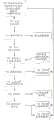
图7是供一些实施例使用的试管分类方案的流程图;Figure 7 is a flow diagram of a test tube sorting scheme for use with some embodiments;
图8是图示创建供一些实施例使用的DVS数据库的数据流;Figure 8 is a data flow illustrating the creation of a DVS database for use with some embodiments;
图9是创建供一些实施例使用的DVS图像数据库的流程图;Figure 9 is a flow diagram of creating a DVS image database for use with some embodiments;
图10是供一些实施例使用的分类器训练的流程图;Figure 10 is a flowchart of classifier training for use with some embodiments;
图11是供一些实施例使用的使用校准目标来校准相机的示例性方法的流程图;以及11 is a flowchart of an exemplary method of calibrating a camera using a calibration target for use with some embodiments; and
图12是供一些实施例使用的用来操作DVS的数据和处理模块的流程图。12 is a flow diagram of data and processing modules used to operate a DVS for use with some embodiments.
具体实施方式Detailed ways
与一些实施例相关联的术语和概念Terms and Concepts Associated with Some Embodiments
分析仪:自动化临床分析仪(“分析仪”)包括临床化学分析仪、自动化免疫测定分析仪或任何其他类型的体外诊断(IVD)测试分析仪。一般地,分析仪对多个病人样品执行一系列自动化IVD测试。病人样品可以被(手动或经由自动化系统)加载到分析仪中,所述分析仪然后可以对每个样品执行一个或多个免疫测定、化学测试或其他可观察到的测试。术语分析仪可以指代但不限于被配置为模块化分析系统的分析仪。模块化分析系统包括集成且可扩展系统,所述集成且可扩展系统包括通过诸如自动化轨道之类的自动化表面以线性或其他几何配置互连的多个模块的任何组合(其可以包括相同类型的模块或不同类型的模块)。在一些实施例中,自动化轨道可以被配置为在其上独立承载器被用来在模块之间移动病人样品和其他类型的材料的整体运输系统。一般地,模块化分析系统中的至少一个模块是分析仪模块。模块可以被专门化或使之冗余以允许对病人样品的分析任务的较高吞吐量。Analyzers: Automated clinical analyzers ("Analyzers") include clinical chemistry analyzers, automated immunoassay analyzers, or any other type of in vitro diagnostic (IVD) test analyzer. Typically, the analyzer performs a series of automated IVD tests on multiple patient samples. Patient samples can be loaded (manually or via an automated system) into an analyzer, which can then perform one or more immunoassays, chemical tests, or other observable tests on each sample. The term analyzer may refer to, but is not limited to, an analyzer configured as a modular analysis system. Modular analysis systems include integrated and expandable systems that include any combination of multiple modules (which may include the same type of modules or different types of modules). In some embodiments, an automated track may be configured as an integral transport system on which individual carriers are used to move patient samples and other types of materials between modules. Typically, at least one module in a modular analysis system is an analyzer module. Modules can be specialized or made redundant to allow higher throughput for analysis tasks on patient samples.
分析仪模块:分析仪模块是模块化分析仪内的被配置成执行IVD测试的模块,所述IVD测试诸如对病人样品的免疫测定、化学测试或其他可观察到的测试。典型地,分析仪模块从样品容器提取液体样品并且在反应比色杯或试管(一般被称为反应容器)中将样品与试剂组合。在分析仪模块中可用的测试可以包括但不限于电解质、肾或肝功能、代谢、心脏、矿物、血液紊乱、药物、免疫测定或其他测试的子集。在一些系统中,分析仪模块可以被专门化或使之冗余以允许较高的吞吐量。分析仪模块的功能还可以由不利用模块化方案的独立分析仪来执行。Analyzer Module: An analyzer module is a module within a modular analyzer that is configured to perform IVD tests such as immunoassays, chemical tests, or other observable tests on patient samples. Typically, an analyzer module extracts a liquid sample from a sample container and combines the sample with reagents in reaction cuvettes or test tubes (commonly referred to as reaction containers). Tests available in the analyzer module may include, but are not limited to, a subset of electrolytes, kidney or liver function, metabolism, cardiac, minerals, blood disorders, drugs, immunoassays, or other tests. In some systems, analyzer modules may be specialized or made redundant to allow higher throughput. The functions of the analyzer module can also be performed by a stand-alone analyzer that does not utilize a modular approach.
承载器:承载器是可以被用来在自动化系统中移动样品容器(以及,通过扩展,移动流体样品)或其他物品的运输单元。在一些实施例中,承载器可以是简单的,比如传统的自动化圆盘(例如,被动设备,其包括用于连接(engage)试管或物品的支持物、用以允许自动化轨道中的外部传送带提供动力的摩擦表面、以及允许由自动化轨道中的墙或铁轨引导圆盘以允许轨道将圆盘传送到其目的地的多个侧面)。在一些实施例中,承载器可以包括主动组件,诸如处理器、运动系统、引导系统、传感器等。在一些实施例中,承载器可以包括允许在自动化系统中的点之间自引导承载器的机载智能。在一些实施例中,承载器可以包括提供动力的机载组件,而在其他实施例中,动力可以由诸如轨道之类的自动化表面提供。在一些实施例中,承载器沿着将运动限制到决策点之间的单个方向(例如,从头到尾)的自动化轨道移动。承载器可以按照IVD环境中的给定有效负载被专门化,诸如具有用以连接和承载样品试管的试管座,或可以包括适合于承载在自动化系统周围的不同物品的安装表面。承载器可以被配置成包括一个或多个狭槽(例如,承载器可以支持样品容器中的一个或多个)。Carrier: A carrier is a transport unit that can be used to move sample containers (and, by extension, fluid samples) or other items in an automated system. In some embodiments, the carrier may be as simple as a conventional automated puck (eg, a passive device that includes a holder for engaging a test tube or item, to allow an external conveyor in an automated track to provide powered friction surfaces, and multiple sides that allow the puck to be guided by a wall or rail in an automated track to allow the track to deliver the puck to its destination). In some embodiments, the carrier may include active components such as processors, motion systems, guidance systems, sensors, and the like. In some embodiments, the carrier may include onboard intelligence that allows the carrier to self-steer between points in the automation system. In some embodiments, the carrier may include an onboard component that provides power, while in other embodiments, the power may be provided by an automated surface such as a track. In some embodiments, the carrier moves along an automated track that restricts movement to a single direction (eg, from end to end) between decision points. The carrier may be specialized for a given payload in an IVD environment, such as having a tube holder to attach and carry sample tubes, or may include mounting surfaces suitable for carrying different items around the automated system. The carrier can be configured to include one or more slots (eg, the carrier can support one or more of the sample containers).
承载器/托盘/支架:承载器可以与托盘可区分,所述托盘可以通常指代不沿着自动化轨道行进(例如,由操作者携带)并且被配置成支持多个有效负载(例如,样品试管)的设备。支架是用以描述被配置成支持多个有效负载(例如,样品试管)的设备的一般术语。支架可以指代被配置成承载多个有效负载的托盘(当自动化轨道外部使用时)或承载器(当被配置成横过自动化轨道时)。在一些实施例中,支架可以指代狭槽的一维或二维阵列。Carrier/Tray/Rack: A carrier can be distinguished from a tray, which can generally refer to not traveling along an automated track (eg, carried by an operator) and configured to support multiple payloads (eg, sample test tubes) )device of. A rack is a general term used to describe a device that is configured to support multiple payloads (eg, sample tubes). A rack may refer to a pallet (when used externally of an automation track) or a carrier (when configured to traverse the automation track) that is configured to carry multiple payloads. In some embodiments, a stent may refer to a one-dimensional or two-dimensional array of slots.
体外诊断(IVD):体外诊断(IVD)是可以检测疾病、状况、感染、代谢指标或者量化身体物质/体液的各种成分的测试。在病人的身体外部,在实验室、医院、医师办公室或其他健康专业设置中执行这些测试。IVD测试一般地利用意图的医疗设备来根据在试管或其他样品容器中的、或更一般地在活有机体外部的受控环境中的化验来执行诊断。IVD包括基于对病人流体样品执行的化验来测试和诊断疾病或者量化身体物质/体液的各种成分。IVD包括可以通过分析从病人的体液或脓肿取得的液体样品而执行的与病人诊断和治疗相关的各种类型的分析测试和化验。典型地用包含病人样品的试管或药瓶已经被加载到其中的分析仪来实施这些化验。IVD可以指代在本文中描述的IVD功能的任何子集。In Vitro Diagnostics (IVDs): In vitro diagnostics (IVDs) are tests that can detect diseases, conditions, infections, metabolic markers, or quantify various components of body substances/fluids. These tests are performed outside the patient's body, in a laboratory, hospital, physician's office, or other health professional setting. IVD testing generally utilizes the intended medical device to perform a diagnosis based on an assay in a test tube or other sample container, or more generally in a controlled environment outside a living organism. IVD involves testing and diagnosing diseases or quantifying various components of bodily substances/fluids based on assays performed on patient fluid samples. IVD includes various types of analytical tests and assays related to patient diagnosis and treatment that can be performed by analyzing fluid samples taken from the patient's bodily fluids or abscesses. These assays are typically performed with an analyzer into which a test tube or vial containing a patient sample has been loaded. IVD can refer to any subset of IVD functions described herein.
实验室自动化系统:实验室自动化系统包括可以自动地(例如,应操作者或软件的请求)样品容器或其他物品使实验室环境内往复运动(shuttle)的任何系统。关于分析仪,自动化系统可以将容器或其他物品自动地移动到分析仪中的站、从分析仪中的站移动、在分析仪中的站之中或之间移动。这些站可以包括但不限于模块化测试站(例如,可以专门进行某些类型的化验或可以以其他方式向较大分析仪提供测试服务的单元)、样品处理站、存储站或工作单元。Laboratory Automation System: A laboratory automation system includes any system that can automatically (eg, at the request of an operator or software) a sample container or other item shuttle within a laboratory environment. With regard to the analyzer, the automated system can automatically move containers or other items to, from, among or between stations in the analyzer. These stations may include, but are not limited to, modular test stations (eg, units that may specialize in certain types of assays or may otherwise provide testing services to larger analyzers), sample processing stations, storage stations, or work cells.
模块:模块执行模块化分析系统内的具体的(一个或多个)任务或(一个或多个)功能。模块的示例可以包括:预分析模块,其准备用于分析测试的样品(例如,开瓶器模块,其移除样品试管顶部上的盖);分析仪模块,其提取样品的一部分并且执行测试或化验;后分析模块,其在分析测试之后准备用于存储的样品(例如,再压盖机(recapper)模块,其重新密封样品试管);或样品处理模块。样品处理模块的功能可以包括出于存货管理的目的而管理样品贮存器/容器、对它们分类、将它们移动到自动化轨道(其可以包括整体运输系统)上或者使它们离开所述自动化轨道、将样品贮存器/容器移动到分离的实验室自动化轨道上或者使其离开所述分离的实验室自动化轨道,以及将样品贮存器/容器移动到托盘、支架、承载器、圆盘和/或存储位置中或者将其移出所述托盘、支架、承载器、圆盘和/或存储位置。Module: A module performs a specific task(s) or function(s) within a modular analysis system. Examples of modules may include: a pre-analysis module, which prepares the sample for analysis of the test (eg, a corkscrew module, which removes the cap on the top of the sample tube); an analyzer module, which extracts a portion of the sample and performs the test or Assays; post-analytical modules, which prepare samples for storage after analytical testing (eg, recapper modules, which reseal sample tubes); or sample processing modules. Functions of the sample processing module may include managing sample repositories/containers for inventory management purposes, sorting them, moving them onto or off automated tracks (which may include an overall transport system), Moving sample reservoirs/containers onto or off a separate laboratory automation track, and moving sample reservoirs/containers to trays, racks, carriers, discs, and/or storage locations into or out of the tray, rack, carrier, puck and/or storage location.
处理器:处理器可以指代一个或多个处理器和/或相关的软件及处理电路。这可以包括单或多核处理器、嵌入式系统或分布式处理架构,酌情用于实现每个实施例中的叙述的处理功能。Processor: A processor may refer to one or more processors and/or associated software and processing circuitry. This may include single or multi-core processors, embedded systems, or distributed processing architectures, as appropriate, for implementing the processing functions recited in each embodiment.
试管/样品容器/流体贮存器:可以在诸如试管或其他适合的容器之类的容器中承载样品,以允许承载器在不污染承载器表面的情况下运输样品。Test Tubes/Sample Containers/Fluid Reservoirs: Samples may be carried in containers such as test tubes or other suitable containers to allow the carrier to transport the sample without contaminating the surface of the carrier.
示例性实施例Exemplary Embodiment
本发明的实施例涉及捕获试管托盘的图像,所述试管托盘被配置成适合在抽屉内并且在被以行和列的阵列布置的狭槽中保持多个试管,并且更特别地涉及训练和校准用于该任务的系统。由观看试管托盘的相机捕获的图像被用来表征托盘以及在托盘上保持的试管。特别地,根据实施例,通过分析图像,可以确定试管的各种特征,诸如例如试管的高度、直径和中心点、试管具有盖还是管顶杯、条形码在试管的顶表面上(例如,盖上)还是在托盘上,并且标识包含试管的托盘狭槽。始终讨论可以经由这些图像确定的样品试管的其他特征。该信息在其中样品处理机处理试管并且将试管移动到分析仪用于测试和分析的IVD环境中是有价值的。本发明的实施例特别良好地适合于但决不限于IVD环境。Embodiments of the present invention relate to capturing images of test tube trays configured to fit within a drawer and hold a plurality of test tubes in slots arranged in arrays of rows and columns, and more particularly to training and calibration The system used for this task. Images captured by a camera looking at the tube tray are used to characterize the tray and the tubes held on the tray. In particular, according to an embodiment, by analyzing the images, various characteristics of the test tube may be determined, such as, for example, the height, diameter and center point of the test tube, whether the test tube has a cap or a tube top cup, the barcode on the top surface of the test tube (eg, the cap on ) is still on the tray and identifies the tray slot containing the tube. Additional features of the sample tube that can be determined via these images are always discussed. This information is valuable in an IVD environment where the sample handler handles the cuvette and moves the cuvette to the analyzer for testing and analysis. Embodiments of the present invention are particularly well suited for, but in no way limited to, IVD environments.
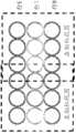
供本文中公开的方法使用的示例性系统是在共有的PCT申请号PCT/US14/27217中讨论的抽屉视觉系统,所述PCT申请号PCT/US14/27217通过引用以其整体被并入在本文中。图1是根据实施例的系统100的表示,其中通过获得和分析其图像来表征被包含在其上的试管托盘120和试管130。一个或多个抽屉110可在打开和关闭位置之间移动,并且被提供在用于样品处理机的工作包封105中。一个或多个试管托盘120可以被加载到抽屉110中或可以是抽屉110的永久部件。每个试管托盘120具有其中可以容纳试管130的狭槽的行和列的阵列(如在示例性托盘121中描绘的那样)。An exemplary system for use with the methods disclosed herein is the drawer vision system discussed in commonly owned PCT Application No. PCT/US14/27217, which is incorporated herein by reference in its entirety middle. 1 is a representation of a
根据可以与本文中公开的概念一起使用的成像系统的一些实施例,拍摄试管托盘120的图像;分析图像以确定试管托盘120和试管130的特性。根据本文中提供的实施例,使用移动的托盘/固定的相机方案来捕获图像用于对其分析。当例如通过手动地或自动地推入抽屉110将试管托盘120移动到工作包封105中时,使用图像捕获系统140来拍摄试管托盘120和包含在其上的试管130的图像。根据实施例,图像捕获系统140包括被定位在工作包封105的入口处或附近的一个或多个相机。该一个或多个相机可以被定位在试管托盘120的表面之上。例如,可以将相机放置在表面之上三到六英寸以捕获试管托盘120的高分辨率图像。取决于相机的特征和所期望的视角和图像质量,还可以使用其他距离和/或定位。可选地,图像捕获系统140可以包括一个或多个照明源,诸如LED闪光灯。当已经要求试管托盘120滑动到工作包封105中时,添加固定的图像捕获系统140不向工作包封105添加过量的成本或复杂度。图像捕获系统140还包括用来执行图像捕获算法的一个或多个处理器,如下面进一步描述的。According to some embodiments of an imaging system that can be used with the concepts disclosed herein, an image of the
根据实施例,每当一行试管托盘120被移动到中心位置或基本上定心在该一个或多个相机下面的位置中时,图像捕获系统140捕获图像。多于一行试管130可以被捕获在该图像中,其中一行被定心或基本上定心在图像捕获系统140下方,而邻近行被从某个斜角捕获在相同图像中。通过一次捕获多于一行,从多个视角捕获多行试管130,提供针对每个试管130的将在图像中捕获的深度和视角信息。According to an embodiment, the
根据实施例,当在多个图像中捕获一行试管130时,捕获该行试管130的三视觉视角(tri-scopic perspective)。例如,当前一行定心或基本上定心在图像捕获系统140下方时,单个行可以出现在图像的底部中(从某个斜视角);当该行试管其本身定心或基本上定心在图像捕获系统140下方时,该单个行然后可以基本上定心在图像中而出现(从基本上自顶向下的视角);并且当后一行试管定心或基本上定心在图像捕获系统140下方时,并且该单个行可以出现在图像的顶部中(从另一斜视角)。在另一实施例中,随着在图像捕获系统140定心或基本上定心在两个邻近行之间的点之上(允许每行以两个斜视角出现在两个图像中)时拍摄图像,可以捕获一行试管的立体视角。类似地,行可以以多于三个视角出现在多于三个图像中,允许从多个图像搜集关于每个试管的更多三维信息。本发明不限于该行试管130的三视觉视角和立体视角;替代地,取决于相机的特征和图像捕获系统140相对于工作包封105的定位,可以获得附加的视角。According to an embodiment, when a row of
图2A-2F提供在捕获一行试管130的示例性图像时的工作包封105的图示。随着该行前进到工作包封105中,图像捕获系统140捕获该行试管130的多个视角。如在图2A-2C中示出的那样,随着行7移动到工作包封105中(即,抽屉110滑动到工作包封105中),直接或几乎直接在所述一个或多个相机下捕获行7的图像,允许行7基本上出现在图像的中心中(例如,如图在2C中示出的那样)。在该示例中,使用两个相机,右和左相机。图2A图示这些相机在行7的图像处的视野。在一些实施例中,这些相机的视野可以重叠。图2B示出允许图像被捕获的示例性情形。随着抽屉110关闭,行130经过图像捕获系统140的视野,允许连续图像被拍摄。图2C示出可以被捕获的示例性灰度图像,其示出行7的顶图像和行6和8的斜图像。随着抽屉关闭,可以在行6和8头顶上捕获类似图像。图2D-2F图示在行7进一步前进到工作包封105中时并且在行8定心或基本上定心在所述一个或多个相机下方时捕获的行7的(例如,如在图2F中示出的)后一斜视角图像(和行8的顶图像,以及行9的斜视角图像)。图2A-2F的系列图示从图像获得的信息的深度,使得能够确定以下特性:集合中的每个试管130的中心点(例如,由对应于试管座的相关图像特征确定的x-y位置);每个试管130的高度(例如,与两个邻近图像之间的试管的顶部的像素距离相关);每个试管的直径(例如,通过观察在每个试管的顶部处形成的圆形或椭圆形的像素大小或通过每个图像中的试管的每侧之间的像素距离);试管130在其顶表面上具有盖还是管顶杯;试管130上的标识信息(即,放置在试管130的盖上的标识符,诸如条形码);或对于普通技术人员而言将显而易见的其他特性。2A-2F provide illustrations of the working
在一些实施例中,可以将一维或二维条形码/QR码放置在试管盖上或托盘的表面上。可以处理经由图像捕获系统140捕获的图像以读取该信息。这可以揭露包含在样品试管中的样品的身份或关于样品的性质的信息,诸如所包含的体液的类型或样品是否是高优先级。在一些实施例中,盖的颜色可以指示优先级、类型或其他状态信息,被可以通过处理由图像捕获系统捕获的图像来确定。在一些实施例中,由图像捕获系统观察到的颜色或标签可以指示样品试管包含校准流体或控制。In some embodiments, a one-dimensional or two-dimensional barcode/QR code may be placed on the lid of the test tube or on the surface of the tray. Images captured via
在一些实施例中,可以使用多个类型的托盘。例如,较大的托盘可以用来运输较大数量的样品试管,而较小的托盘可以用来运输较小数量的样品,这在运输诸如校准物和STAT样品之类的专用样品试管时可以是有用的。可以经由托盘上的光学标志比如QR码将托盘的类型传送到图像捕获系统140。QR码或其他光学标志还可以将托盘方位、托盘优先级、身份/编号、大小、物理性质(诸如狭槽的数量、版本等)传送到图像捕获系统。通过分析标志的所捕获的图像,抽屉视觉系统可以快速地预测托盘的范围,并且在一些实施例中通过使用基于从光学标志接收的信息的托盘的模型更好地分析试管的图像。In some embodiments, multiple types of trays may be used. For example, a larger tray can be used to transport a larger number of sample tubes, while a smaller tray can be used to transport a smaller number of samples, which can be useful when transporting specialized sample tubes such as calibrators and STAT samples useful. The type of tray may be communicated to image
在一些实施例中,当样品试管缺少盖时,可以处理经由图像捕获系统140捕获的图像以在过程中的早期确定关于样品的质量和样品试管或托盘的任何缺陷或异常特性的信息。例如,样品试管侧面上的剥离标签可以引起关于随后处理的问题。剥离标签可以在自顶向下的图像中可见,或者在斜图像中可见,如果它不平放在试管表面上的话。如果试管是湿的或具有冷凝,则其可以引起关于紧握的问题。如果足够严重,则冷凝液滴可以作为折射或反射珠可观察到。如果试管具有裂缝或其他物理缺陷,则这可以是可观察到的并且在自顶向下或斜图像的图像分析期间被检测到。图像分析还可以检测试管相对于其他试管倾斜,这可能在样品处理机器人手臂与试管交互时定位所述样品处理机器人手臂方面是有用的。In some embodiments, images captured via
如果样品已经被误处理,则其可能发泡或起泡。这可以影响稍后的读数并且可以经由图像分析而检测到。如果状况足够严重,则发泡或起泡可以在自顶向下或斜图像中可检测出,并且系统可以警告操作者可能需要新样品。在一些实施例中,还可以检测到样品的异常质量。例如,异质图像或试管中的异质对象可以指示碎片或样品污染,如果其足够严重到出现在图像中的话。还可以观察到其他品质。还可以通过对自顶向下或斜图像的图像分析来确定流体高度的估计,其可以提供可能需要附加的流体量的早期警告。在一些实施例中,可以经由对自顶向下或斜图像的图像分析来确定关于托盘的状况的错误。例如,如果观察到光辉或其他光学异常,则可以确定托盘上的狭槽中的溢出物的存在。类似地,如果未观察到正常与试管或空狭槽一致的图案而是观察到异常内含物,则可以确定碎片或对象的存在。此外,如果托盘中的标志或结构超出所预期图案(诸如条形码或QR码或定位标记)的范围,则这可以指示托盘被磨损或损坏。如果任何这些状况存在,则可以警告操作者。If the sample has been mishandled, it may foam or blister. This can affect later readings and can be detected via image analysis. If the condition is severe enough, foaming or blistering can be detected in a top-down or oblique image, and the system can warn the operator that a new sample may be required. In some embodiments, abnormal quality of the sample may also be detected. For example, a heterogeneous image or a heterogeneous object in a test tube can indicate debris or sample contamination if it is severe enough to appear in the image. Other qualities can also be observed. Estimates of fluid height can also be determined by image analysis of top-down or oblique images, which can provide early warning that additional fluid volumes may be required. In some embodiments, errors regarding the condition of the tray may be determined via image analysis of top-down or oblique images. For example, if brilliance or other optical anomalies are observed, the presence of spills in the slots on the tray can be determined. Similarly, if a pattern normally consistent with a test tube or empty slot is not observed but abnormal inclusions are observed, the presence of debris or objects can be determined. Additionally, if the markings or structures in the tray are outside the range of the expected pattern, such as a barcode or QR code or locator markings, this can indicate that the tray is worn or damaged. If any of these conditions exist, the operator can be alerted.
在没有与试管130、试管托盘120或抽屉110的接触的情况下获得这些特性。替代地,通过获得在不同的视角中的图像,可以对图像执行立体分析。例如,可以通过比较试管顶部的中心在随后的图像之间移动多少来确定试管130的高度。以类似的方式,可以确定试管130和试管托盘120的各种其他特性。These properties are obtained without contact with the
利用顶置相机来以本文中描述的任何方式表征试管托盘中的试管的系统可以被称为抽屉视觉系统(DVS)。图3示出根据实施例的用于通过图像分析来表征在抽屉110中保持的试管托盘120和被包含在其上的试管130的示例性DVS系统500的框图表示。根据实施例,图像捕获系统140包括两个相机,左相机542和右相机544。取决于抽屉110和试管托盘120的大小以及所期望的图像质量和图像视角,可以包括附加的或更少的相机。光源546和图像捕获控制器548也是图像捕获系统140的部分。A system that utilizes an overhead camera to characterize tubes in a tube tray in any of the ways described herein may be referred to as a drawer vision system (DVS). 3 illustrates a block diagram representation of an
在实施例中,为了准确地捕获图像并且考虑到抽屉110/试管托盘120正在移动,相机542、544使用快到足够实质上产生停格摄影(stop motion photography)的快门速度来捕获图像。在一些实施例中,光源546可以与相机542、544的触发同步以在帮助闪光或停格摄影。在其他实施例中,光源546可以持续开着,或者可以在第一次检测到抽屉110/试管托盘120的运动时被触发打开。在一些实施例中,使用容许250微秒曝光时间的相机。在其他实施例中,取决于例如照明、抽屉110/试管托盘120的速度以及所期望的图像质量,可以使用具有其他能力的相机。In an embodiment, in order to accurately capture the image and take into account that the
进一步参考图3,诸如正交编码器之类的编码器510用来确定试管托盘120的行何时移动到所述一个或多个相机542、544下方的中心或基本上中心的位置中。在检测到与试管托盘120的新行移动到所述一个或多个相机542、544下方的中心或基本上中心的位置对应的试管托盘120的移动时,编码器510向图像捕获控制器548发射信号(即,脉冲)。检测基于编码器510根据指示抽屉110和/或试管托盘120已经移动一行的槽口(notch)递增。信号充当用于图像捕获控制器548在接收到信号时命令相机542、544拍摄图像的指令。如上面描述的那样,在一些实施例中,编码方案可以对应于其他移动,诸如例如抽屉110/试管托盘120移动两行或者抽屉110/试管托盘120移动到在两行之间居中的位置中。在其中抽屉110/试管托盘120被移动到工作包封105中的时间段期间,图像捕获控制器548管理由相机542、544拍摄的图像的存储。该时间段还可以包括抽屉110/试管托盘120被移出工作包封105(例如,抽屉110/试管托盘120可以被推入到工作包封105中,被部分地拉出工作包封105,然后被推回到工作包封105中)。一个或多个内部或外部存储器设备可以与图像捕获控制器548相关联,诸如存储器540。在一个实施例中,一个或多个存储器设备中的一个包括其中存储表的随机存取存储器(RAM),该表包含由相机542、544拍摄的图像。图像捕获系统140可以在每个抽屉110/试管托盘120的开端和末端处捕获附加的图像行以便确保从相同数量的视角看到托盘中的所有行(否则,在末端处的行将不被从一侧捕获)。另外,图像捕获系统140可以捕获针对所有行的额外的图像行以便生成关于每个试管的附加的视角并且以便帮助确定某些特征。图像捕获系统140还可以捕获额外的图像行以便检测样品处理机工作包封105中的特征,以便将托盘120定位在工作包封105内并且按照样品处理机的坐标系自动校准托盘120。图像捕获系统140在与托盘120和样品处理机工作包封105的特征具有固定关系的预定位置处捕获固定数量的图像行。With further reference to FIG. 3 , an
图像捕获系统140可以捕获和存储与托盘的预定成像位置的每个成像对应的单个图像。例如,如果托盘具有10行,并且每行应该在三个邻近图像中出现以提供每行的两个斜视角和一个基本上中心的视角,则可以存储在十二个连续成像位置处拍摄的托盘的十二个图像。当捕获给定行的特定视角的新图像时,重写与该成像位置对应的先前存储的图像。例如,考虑以下场景:当行10推入到抽屉110中并且定心或基本上定心在图像捕获系统140的相机542、544下方时捕获图像。如果随后抽屉110被拉出并且然后推入使得行10再次定心或基本上定心在图像捕获系统140下方,则拍摄该视角的第二图像。该第二图像重写第一图像。该实现导致固定量的存储以及固定量的处理时间。The
在一些实施例中,图像可以被缓冲直到抽屉完全关闭。缓冲图像直到抽屉110完全关闭和触发固定位置上的相机542、544可以克服与随机抽屉移动相关联的挑战。特别地,不获取图像,除非抽屉110的固定位置定心或基本上定心在所述一个或多个相机542、544下方,使抽屉110的轻微运动,诸如偶然碰撞被图像捕获系统忽视。作为结果,在相对于抽屉的预定成像位置处拍摄的图像的集合可用于随后的处理以确定试管和抽屉的特性。In some embodiments, the image may be buffered until the drawer is fully closed. Buffering the image until the
控制器520被提供用于管理对由相机542、544拍摄的图像的图像分析。在检测到抽屉110的关闭时,图像捕获控制器548将图像提供给控制器520用于下载和处理。根据实施例,控制器520是样品处理机的部分,其在IVD环境中用来处理试管托盘120和试管130以及使其在存储位置(诸如工作包封105)到分析仪之间移动。由控制器520执行的图像分析用于关于试管托盘120和试管130的各种确定的特性命令样品处理机,从而允许样品处理机相应地处置和处理试管托盘120和试管130。A
所述一个或多个存储器设备540与控制器520相关联。所述一个或多个存储器设备540可以在控制器520内部或外部。一个或多个抽屉传感器530可以被连接到控制器520以指示抽屉110何时完全关闭和/或抽屉110何时完全打开。根据实施例,抽屉110完全关闭充当开始对所捕获和存储的图像进行图像处理的指示。当抽屉110完全关闭时,抽屉传感器530向控制器520发送信号。The one or more memory devices 540 are associated with the
图4提供根据实施例的控制器520的框图表示。抽屉管理器521管理在控制器520的各种模块之中的数据流。根据一些实施例可以是USB收发机的收发机522从图像捕获控制器548接收数据(即,所捕获的图像)。数字输入/输出(I/O)管理器523管理信号的接收以及信号在抽屉传感器530和控制器520之间的传输。当I/O管理器523从抽屉传感器530接收指示抽屉110完全关闭的信号时,I/O管理器523将该信号传送到抽屉管理器521,所述抽屉管理器521向收发机522发布下载图像的请求。抽屉管理器521将所下载的图像提供到图像处理器524用于对其进行处理。可以经由抽屉管理器521将由图像处理器524处理的数据发送到机器人手臂管理器525,所述数据包括试管托盘120和在其上的托盘130的特性。机器人手臂管理器525是控制器520的与处理和运输试管托盘120和试管130相关联的模块(即,样品处理机)。因此,机器人手臂处理器525利用由图像处理器524处理的数据。FIG. 4 provides a block diagram representation of a
根据实施例,图像处理器524基于先入先出算法处理图像。因此,机器人手臂管理器525可以在图像处理器524处理与第二行相关的图像同时处理/处置第一行的试管130。由于机器人手臂管理器525不同时要求所有特性数据,因此不要求图像处理器524在机器人手臂管理器525准备好开始其功能以前处理了所有图像数据。根据实施例,机器人手臂管理器525处理一行试管130所要求的时间近似3秒,从而允许由图像处理器524执行的图像分析花费多达每行3秒。因此,当图像捕获是实时的时,图像分析不是实时的。这极大地减小了图像处理器524的所要求的处理速度和能力。According to an embodiment, the
为了提供DVS的功能,在处理图像的一个或多个处理器(诸如图像处理器524)上运行操作的软件需要被修整以处理在抽屉系统中看到的图像的类型。所期望的是校准软件以计及物理/光学相机性质并且进一步训练所述软件以从现实世界图像识别试管情形。In order to provide the functionality of the DVS, the software that operates on one or more processors that process images, such as
在一些实施例中,从软件立场来看,存在DVS的两个部分:在线部分和离线部分。在线指代在操作期间,即当系统处理由相机捕获的新图像时以及当系统在实验室中的操作期间正用于发现抽屉存货时,发生的那些部分。离线指代在正常实验室工作流程中的对样品进行操作之前进行的对DVS的任何训练和校准。一般地,离线步骤在制造时被执行并且可能偶尔在DVS的寿命期间被执行以维持校准。当DVS在处理样品的实验室中操作时频繁地执行在线步骤。In some embodiments, from a software standpoint, there are two parts of the DVS: an online part and an offline part. Online refers to those parts that occur during operation, ie, when the system is processing new images captured by the camera, and when the system is being used to discover drawer inventory during operation in the laboratory. Offline refers to any training and calibration of the DVS performed prior to manipulation of the sample in the normal laboratory workflow. Typically, off-line steps are performed at the time of manufacture and may occasionally be performed during the life of the DVS to maintain calibration. Online steps are frequently performed when the DVS operates in a laboratory that processes samples.
离线训练对确定不同的试管类型特别有用。一旦范围被限定成确定要用于系统的试管类型,那些试管的图像就可以限定用于训练的集合。针对训练,所期望的是具有允许DVS检测不同的试管类型的用于训练分类器组件的大量数据。可以在工厂处进行一次训练,并且可以或可以不在消费者的房屋处重复所述训练。关于房屋的训练将允许消费者将图像训练定制成在特定实验室中使用的试管类型和大小。在粗略的意义上,训练可以被认为是在制造商侧发生的某事。在一些实施例中,训练可以针对装运有DVS的所有实例的软件包发生一次,而在其他实施例中,可以按照DVS的每个实例修整训练。其他离线组件、校准可以发生在消费者的场所处或在DVS的每个实例的制造商处。然而,训练涉及解释由DVS的相机捕获的图像中的突出特征,校准涉及表征那些相机的物理和光学性质以辅助解释图像。因为每个DVS是分离的物理设备,所以每个可以具有足够的物理变化以保证对每个DVS设备的校准。因此,在一些实施例中,当每个DVS被安装在消费者场所处时或者在制造DVS之后,对所述每个DVS进行校准,同时可以预加载训练数据。在一些实施例中,还可以稍后执行再训练。Offline training is particularly useful for identifying different tube types. Once the scope is defined to determine the types of tubes to be used with the system, images of those tubes can define the set used for training. For training, it is desirable to have a large amount of data for training the classifier component that allows DVS to detect different test tube types. The training may be performed once at the factory and may or may not be repeated at the consumer's premises. Training on houses will allow consumers to tailor image training to the type and size of tubes used in a particular lab. In a rough sense, training can be thought of as something that happens on the manufacturer's side. In some embodiments, training may occur once for a software package that ships with all instances of DVS, while in other embodiments, training may be tailored per instance of DVS. Other off-line components, calibration can take place at the customer's site or at the manufacturer of each instance of the DVS. Whereas training involves interpreting prominent features in images captured by the DVS's cameras, calibration involves characterizing the physical and optical properties of those cameras to aid in the interpretation of the images. Because each DVS is a separate physical device, each can have enough physical variation to warrant calibration of each DVS device. Thus, in some embodiments, each DVS is calibrated as it is installed at the consumer site or after the DVS is manufactured, while training data may be preloaded. In some embodiments, retraining may also be performed later.
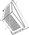
可以使用一系列标记来进行校准。图5示出可以用于校准DVS中的相机的示例性标记。校准目标600包括多个平面602。平面602中的每个包括形成较大光学图案的唯一标记的阵列。示例性的各个标记604包括西门子霍夫曼(Siemens Hoffmann)标记。平面602允许校准目标600呈现唯一标记604的3-D布置。西门子霍夫曼标记通过提供相对于图像平面的已知的2-D空间点而对于校准相机是有用的。每个标记604是唯一的编码块,其与每个平面602上的唯一位置相关。通过提供这些标记的多个平面,目标600呈现然后可以与每个相机的图像平面中的2-D点相关的多个已知3-D空间点。因为每个标记是唯一的,所以相机可以在仅平面的部分视图可用时标识每个平面上的网格位置。按常规,棋盘图案或西门子霍夫曼标记用在常常被以各种姿态(pose)和距离放置在在相机前面的单个2-D平面中。多个平面确保平面上的标记呈现用于相机校准的三维目标,这里在校准目标划过DVS中的相机时每个平面的姿态相对于每个相机变化。在一些实施例中,平面可以被以金字塔或其他形状布置以呈现用于相机校准的3-D目标。Calibration can be performed using a series of markers. FIG. 5 shows exemplary markers that can be used to calibrate a camera in a DVS.
平面602可以被安装在常规试管托盘的顶部上,允许校准目标600在训练期间以试管托盘将在运行时间被处理所用的相同方式由DVS处理。这允许运动机构相对于DVS中的相机来移动标记604。这进一步允许在DVS的运行时间操作期间,每个标记被以样品试管的突出特征将被定位在每个相机的图像平面中的大致相同的方式放置在每个相机的图像平面中的不同位置处。通过利用3-D平坦表面上的标记的阵列,通过使目标600滑动通过抽屉系统和捕获多个图像可以容易地测试多个3-D位置以用于校准。例如,这允许校准图像模拟不同的试管顶部高度。在一些实施例中,DVS包括在抽屉中的行中对齐的多个相机。该行的方向平行于该校准对象中的顶点。该校准对象与一个相机一起工作,也与多个相机一起工作,只要相机可以看到校准对象。The
每个相机具有两个不同类型的性质。第一个被称作固有性质或参数,例如焦距。除了焦距之外,相机的固有参数还可以具有限定的主点,即关于图像的光学中心。第二个被称作外在性质,其包括取决于相机的使用而改变的性质,诸如姿态——相机关于预定义的坐标系定向并且面向何处。固有和外在性质应该被校准。Each camera has two different types of properties. The first is called an intrinsic property or parameter, such as focal length. In addition to the focal length, intrinsic parameters of the camera may also have a defined principal point, ie the optical center with respect to the image. The second is called extrinsic properties and includes properties that change depending on the use of the camera, such as pose - where the camera is oriented and facing with respect to a predefined coordinate system. Intrinsic and extrinsic properties should be calibrated.
通过利用校准目标,诸如目标600,多个相机可以同时经历固有性质校准。另外,因为多个相机看到相同的唯一目标,所以还可以使用这些目标来计算相对于彼此的外在性质。例如,第一相机可以用作参考,允许关于第一相机来估计第二相机的姿态。同时,目标的位置可以用来确定固有参数,诸如每个相机的主点。目标600因此被设计成估计每个相机的固有参数。By utilizing a calibration target, such as
典型地通过将平面放置在相机前面和改变相机或平面的姿态来进行校准。在DVS中,由于抽屉状的结构,空间受限。通过将校准目标安装在试管托盘或模拟试管托盘的对象上,本文中描述的目标可以用来校准受限空间中的DVS相机。理想地,出于校准的目的,仅要求具有非共面3D点的网格的一个图像。然而,在仅网格标记的子集在DVS相机的受限视野内可见的场合,情况常常是这样。另外,对放置在关于相机的不同位置处的网格的多个观察还极大地帮助提高校准的准确性。在固定的相机的情况下,抽屉和目标移动,允许相机拍摄多个图像,其进一步允许具有已知坐标的3-D目标在图像平面中四处移动。这导致目标相对于相机的多个姿态,允许充分的数据来校准每个相机。因为校准目标大到足够跨多相机可见,所以除了每个相机的固有性质之外,校准软件还可以导出相机的每对之间的相对姿态。Calibration is typically performed by placing a plane in front of the camera and changing the pose of the camera or plane. In DVS, space is limited due to the drawer-like structure. The targets described herein can be used to calibrate DVS cameras in confined spaces by mounting the calibration target on a tube tray or an object that simulates a tube tray. Ideally, only one image of a grid with non-coplanar 3D points is required for calibration purposes. However, this is often the case where only a subset of grid markers are visible within the limited field of view of the DVS camera. In addition, multiple observations of the grid placed at different positions with respect to the camera also greatly help improve the accuracy of the calibration. In the case of a fixed camera, the drawer and object move, allowing the camera to take multiple images, which further allows the 3-D object with known coordinates to move around in the image plane. This results in multiple poses of the target relative to the camera, allowing sufficient data to calibrate each camera. Because the calibration target is large enough to be visible across multiple cameras, in addition to the inherent properties of each camera, the calibration software can derive the relative pose between each pair of cameras.
用于校准的软件经由已知3D点的集合


人们可以单独地分解R和t分量,导出旋转矩阵R和平移向量t。R可以被呈现为3x3矩阵,而t可以被呈现为3x1向量,这里


为了执行校准,一个人简单地使校准目标通过抽屉并且捕获图像。因为每个标记的位置在相对于托盘的3-D空间中是已知的,并且在抽屉关闭时的所述抽屉中的托盘的位置可以通过索引或其他手段容易地导出,所以这为等式1中的算法提供充分的信息以解释图像并且解K及t矩阵。因为每个标记是唯一的,所以即使在视野未捕获校准目标的平面的边缘时,也可以为由相机捕获的每个二维图像确定与标记对应的3-D空间中的点。已知的3D点

给定从同时拍摄的一对图像估计的相机A和B的姿态


一旦我们具有两个相机,就估计每个相机的校准参数。等式2和3仅告诉你如何导出相机A和B之间的相对姿态。这是导出相对姿态的常规方案。在这里RA被表征为RA-1,因为你需要将旋转逆转回到坐标然后再投影回到另一坐标系。其是矩阵的逆。Once we have two cameras, estimate the calibration parameters for each camera. Equations 2 and 3 only tell you how to derive the relative pose between cameras A and B. This is the general scheme for deriving relative poses. HereRA isrepresented as RA-1because you need toreverse the rotation back to the coordinates and then project back to another coordinate system. It is the inverse of the matrix.
注意,基于具有已知3-D点的目标来执行上述校准,其可以通过目标上的每个校准点的3-D坐标来提供。当每个标记板上的校准点位于平坦表面的规则网格上时,其全局坐标可以被描述为其局部坐标的刚性变换。从具有整个校准目标在视野中的各种放置的单个相机拍摄的图像允许对这些3D坐标的校准。目标的这两个板之间的刚性变换然后可以经由非线性最小二乘优化导出以推断目标上的所有校准点的3D坐标。Note that the above calibration is performed based on a target with known 3-D points, which can be provided by the 3-D coordinates of each calibration point on the target. When the calibration points on each marker plate lie on a regular grid of flat surfaces, their global coordinates can be described as rigid transformations of their local coordinates. Images taken from a single camera with various placements of the entire calibration target in the field of view allow calibration of these 3D coordinates. The rigid transformation between these two plates of the target can then be derived via nonlinear least squares optimization to infer the 3D coordinates of all calibration points on the target.
一旦相机被校准,其就可以用来训练图像检测算法以利用这些参数来解释试管托盘中的样品试管的现实世界图像,从而允许对DVS系统中的每个试管托盘的内含物的光学表征。在一些实施例中,训练过程使用试管中的实际体液,而在其他实施例中,出于健康和安全的目的而使用模拟的体液。例如,可以使用与血液类似粘度的鲜红流体来模拟血液。可以捕获试管托盘中的示例性样品试管中的模拟的或真实的流体的图像。可以准备这些训练样品以通过改变试管的填充高度来模拟现实世界样品。所使用的样品试管可以具有将在实验室环境中出现的样品试管的相同类型,诸如高度、直径、材料等。可以使用各种流体类型,包括血清、血液和尿液,其每个都可以被模拟。在一些实施例中,较大比例的训练样品可以是血清,其可以更好地近似现实世界的使用。Once the camera is calibrated, it can be used to train an image detection algorithm to utilize these parameters to interpret real-world images of sample tubes in a tube tray, allowing optical characterization of the contents of each tube tray in the DVS system. In some embodiments, the training process uses actual bodily fluids in test tubes, while in other embodiments, simulated bodily fluids are used for health and safety purposes. For example, blood can be simulated using a bright red fluid with a viscosity similar to blood. Images of simulated or real fluids in exemplary sample tubes in the tube tray can be captured. These training samples can be prepared to simulate real world samples by varying the fill height of the test tubes. The sample cuvettes used may be of the same type, such as height, diameter, material, etc., of sample cuvettes that would be found in a laboratory environment. Various fluid types can be used, including serum, blood, and urine, each of which can be simulated. In some embodiments, a larger proportion of the training samples may be serum, which may better approximate real world usage.
可以使用包括示例性DVS系统的测试装具(harness)和包含各种训练样品试管的试管托盘来训练图像处理器。试管可以包括多种不同的试管位置,并且可以包括托盘上的标记,其可以对关于每个样品试管的特性的地面实况进行编码。这允许一个或多个训练托盘滑动到DVS中,从而允许相机从每个试管的各种角度捕获多个图像。试管的这些图像可以被划分成与每个试管对应的图像块,从而允许运行随机森林分类算法。The image processor can be trained using a test harness including an exemplary DVS system and a tube tray containing various training sample tubes. The tubes can include a variety of different tube positions, and can include markings on the tray that can encode ground truth about the properties of each sample tube. This allows one or more training trays to slide into the DVS, allowing the camera to capture multiple images from various angles of each tube. These images of test tubes can be divided into image patches corresponding to each test tube, allowing the random forest classification algorithm to be run.
在一些实施例中,与每个试管对应的图像块被改变尺寸成64x64像素,以提供标准化的训练图像块。该标准化对于尺度图像而言可能是必要的,其中由于距离,图像的与样品试管对应的一部分小于与图像中心处的样品试管对应的图像的部分。已经在相机校准过程期间移除了畸变,因为解决了任何透镜畸变因素。一般地,用已经被分解出来的任何透镜畸变来捕获图像块。在一些实施例中,这些标准化的图像块可以进一步旋转90、180和270度以生成新块,其在训练期间可以用来添加数据变化。诸如被放置在试管托盘的表面上的白点之类的基准标志可以用来标识托盘内的每个试管的行和列位置。图像块中的基准标志可以标识托盘中的哪个狭槽与图像块对应或简单地通过提供参考点来对齐图像内的狭槽。该信息可以是有用的,因为相机不具有托盘内的每个狭槽的相同观看角度。例如,托盘的边缘附近的列中的狭槽可以不直接在相机下面经过,而托盘的中心附近的列中的狭槽可以直接在相机下面经过。相应地,与某些列或行对应的狭槽可以包括图像块中的较陡峭的观看角度。In some embodiments, the image patch corresponding to each test tube is resized to 64x64 pixels to provide a normalized training image patch. This normalization may be necessary for scale images where, due to distance, the portion of the image corresponding to the sample cuvette is smaller than the portion of the image corresponding to the sample cuvette at the center of the image. Distortion has been removed during the camera calibration process as any lens distortion factors are accounted for. Typically, image patches are captured with any lens distortion that has been factored out. In some embodiments, these normalized image patches can be rotated further by 90, 180, and 270 degrees to generate new patches, which can be used to add data changes during training. Fiducial markers such as white dots placed on the surface of the tube tray can be used to identify the row and column location of each tube within the tray. The fiducial marks in the image patch can identify which slot in the tray corresponds to the image patch or simply by providing reference points to align the slots within the image. This information can be useful because the cameras do not have the same viewing angle for every slot in the tray. For example, the slots in the columns near the edge of the tray may not pass directly under the cameras, while the slots in the columns near the center of the tray may pass directly under the cameras. Accordingly, slots corresponding to certain columns or rows may include steeper viewing angles in the image block.
图像块可以包括两个类型的图像块。第一类型的图像块与以每个训练试管的试管顶部为中心的图像的部分对应。可以通过对图像运行常规圆检测图像处理算法以标识可能的试管顶部来选择这些图像块。在一些实施例中,在训练算法用于检测盖或管顶杯的存在的场合,与试管顶部对应的图像块可以被缩放使得所有试管顶部在分类训练期间基本上大小相同。第二类型的图像块与试管可以被插入到其中的狭槽对应。通过标识托盘表面中的狭槽的位置,诸如通过理解相机的姿态校准,如本文中描述的那样,或者通过使用用以标识图像中的物理托盘狭槽的位置的基准标志或其他图像特征的辅助,可以选择与该托盘狭槽的范围对应的图像块。如果托盘狭槽未被占用,则该图像块可以示出与该狭槽对应的干净的圆形结构;如果托盘狭槽被占用,则该图像块可以示出包括样品试管的底部的阻塞的狭槽。Image blocks can include two types of image blocks. The first type of image patch corresponds to the portion of the image centered on the top of each training tube. These image patches can be selected by running conventional circle detection image processing algorithms on the images to identify possible tube tops. In some embodiments, where the training algorithm is used to detect the presence of lids or tube top cups, image patches corresponding to test tube tops may be scaled such that all test tube tops are substantially the same size during classification training. A second type of image patch corresponds to a slot into which a test tube can be inserted. By identifying the location of the slot in the tray surface, such as by understanding the pose calibration of the camera, as described herein, or by using the aid of fiducial markers or other image features to identify the location of the physical tray slot in the image , the image block corresponding to the extent of the tray slot can be selected. If the tray slot is unoccupied, the image block may show a clean circular structure corresponding to the slot; if the tray slot is occupied, the image block may show an obstructed slit including the bottom of the sample tube groove.
一旦收集了图像并且使用测试装具生成了训练图像块,处理器就可以着手特征提取。针对每个图像块,训练算法计算定向的梯度和方向可调(steerable)过滤特征的直方图。算法还可以计算强度值的平均和方差。在特征提取之后,由高维特征向量来表示每个图像块。Once the images are collected and training image patches are generated using the test rig, the processor can proceed to feature extraction. For each image patch, the training algorithm computes a histogram of oriented gradients and steerable filter features. The algorithm can also calculate the mean and variance of the intensity values. After feature extraction, each image patch is represented by a high-dimensional feature vector.
在一些实施例中,托盘包括被附接到托盘的末端以标识托盘和/或托盘类型的2-D条形码或数据标志。当托盘最初被插入到抽屉中时,在托盘的末端附近的条形码将出现在初始图像中并且可以通过用常规的图案匹配技术来标识以定位条形码,或者条形码可以被放置在每个托盘上的基本上统一的位置处。这些条形码可以包含关于托盘类型的信息,其可以将托盘标识为具有15或55个狭槽。在一些实施例中,抽屉被具体地设计成在前面部分上容纳一个55-狭槽托盘并且在后面部分上容纳一个55-狭槽托盘,或者在每个部分上容纳三个15狭槽托盘。相应地,如果标识条形码总是位于托盘的边缘,则在插入托盘时,仅捕获与托盘之间的那些边界对应、需要被搜索并且标识条形码的某些图像。此外,可以由处理器按照托盘的方位理解在这些图像中标识方位标记。维持托盘的定向和布局的适当模型可能对于在图像中标识试管狭槽的预期位置而言是重要的。In some embodiments, the tray includes a 2-D barcode or data mark attached to the end of the tray to identify the tray and/or tray type. When the tray is initially inserted into the drawer, the barcode near the end of the tray will appear in the initial image and can be identified by using conventional pattern matching techniques to locate the barcode, or the barcode can be placed on each tray in a basic at the same location. These barcodes can contain information about the type of tray, which can identify the tray as having 15 or 55 slots. In some embodiments, the drawer is specifically designed to accommodate one 55-slot tray on the front section and one 55-slot tray on the rear section, or three 15-slot trays on each section. Correspondingly, if the identifying barcodes are always located at the edges of the trays, when inserting the trays, only certain images corresponding to those boundaries between the trays that need to be searched for and identify the barcodes are captured. In addition, orientation markings can be identified in these images by the processor in accordance with the orientation of the tray. Maintaining a proper model of the orientation and layout of the tray may be important to identify the expected location of the tube slot in the image.
通过使用校准目标执行相机校准,处理器能够访问用于描述相机的透镜的径向畸变的参数。可以使用这些参数来补偿该径向畸变,使得3-D中的直线在未畸变的经补偿的图像中将出现为直线。对畸变的该补偿可以促进用于托盘级块(例如,试管狭槽块)和试管级块(例如,试管顶部块)两者的块提取的试管狭槽对齐。By performing camera calibration using the calibration target, the processor is able to access parameters describing the radial distortion of the lens of the camera. These parameters can be used to compensate for this radial distortion so that straight lines in 3-D will appear as straight lines in the undistorted compensated image. This compensation for distortion may facilitate cuvette slot alignment for block extraction of both tray-level blocks (eg, cuvette slot blocks) and cuvette-level blocks (eg, cuvette top blocks).
一旦托盘定向类型已经被标识,图像处理器就可以将虚拟的托盘狭槽网格覆盖到图像的模型中。该网格可以包括附加的行和列以允许托盘表面上的任何基准标志的标识。例如,55-狭槽托盘将具有虚拟12 x 6网格。可以通过标识托盘表面上的任何基准标志来将该网格与托盘表面对齐,这里基准标志被布置在表面上的网格中,诸如在每组四试管狭槽之间,并且在边缘处。该网格然后可以用于辅助标识与试管狭槽对应的图像块。网格允许适当地对齐托盘的图像以用于处理。为了唯一地标识基准标记,在托盘滑动到抽屉中时登记的行索引解码器可以标识托盘的物理平移。每个检测到的基准标记与最靠近的编码器标记相关联并且计算平均偏移。这允许即使当由于驻留在狭槽中的样品试管仅几个基准标记在图像中可用而没有闭合时,托盘狭槽网格与托盘图像可靠地对齐。Once the tray orientation type has been identified, the image processor can overlay a virtual grid of tray slots into the model of the image. The grid may include additional rows and columns to allow identification of any fiducial marks on the tray surface. For example, a 55-slot tray would have a virtual 12 x 6 grid. The grid can be aligned with the tray surface by identifying any fiducial marks on the tray surface, where the fiducial marks are arranged in a grid on the surface, such as between each set of four test tube slots, and at the edges. This grid can then be used to assist in identifying image patches corresponding to the test tube slots. The grid allows images of the pallet to be properly aligned for processing. In order to uniquely identify the fiducial marks, a row index decoder registered when the tray is slid into the drawer can identify the physical translation of the tray. Each detected fiducial marker is associated with the closest encoder marker and an average offset is calculated. This allows for reliable alignment of the tray slot grid with the tray image even when only a few fiducial markers are available in the image without closure due to sample tubes residing in the slots.
在覆盖托盘网格之后,算法修剪托盘狭槽块。用触发相机的编码器来捕获相机图像。如果在相机的视野中存在托盘,则所捕获的图像以特定行为中心。给定该信息以及托盘狭槽的行和列索引,该算法计算图像中的感兴趣的可能区域并且应用圆检测算法来检测试管顶部是否在狭槽中存在试管。如果发现圆,则其修剪试管顶层块。试管顶部块连同托盘狭槽块被用作空狭槽检测器和试管类型检测器的输入。块连同地面实况也被收集以离线训练检测器。After covering the pallet grid, the algorithm trims the pallet slot blocks. Capture camera images with an encoder that triggers the camera. If there is a tray in the camera's field of view, the captured image is centered on a specific behavior. Given this information and the row and column indices of the tray slots, the algorithm calculates possible regions of interest in the image and applies a circle detection algorithm to detect the presence of a tube in the slot at the top of the tube. If a circle is found, it trims the top piece of the tube. The Tube Top Block along with the Tray Slot Block is used as the input for the Empty Slot Detector and Tube Type Detector. The blocks are also collected along with the ground truth to train the detector offline.
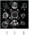
在图6中示出示例性图像和使用该技术提取的示例性图像块。图像610是可以在DVS中的相机的视野中捕获的示例性图像。一旦校准了相机,就针对图像畸变来补偿图像610。可以在图像中检测到白点并且使用其来定向托盘表面的网格覆盖。使用该网格,图像块与试管顶部612和试管狭槽614对应。在该示例中,所有试管具有盖,其可以使用用来导出图像块612的圆检测来标识。类似地,所有狭槽被占用,使得样品试管的部分使与试管狭槽的位置对应的图像块模糊。然而,通过相对于托盘表面来定向网格,图像处理,与所占用的试管狭槽对应的图像块614可以被导出以用于处理狭槽占用的标识。An example image and example image patches extracted using this technique are shown in FIG. 6 .
图像块612和614连同对试管顶部和狭槽占用的地面实况的标识可以用于训练目的。类似地,在实验室中的运行时间期间,图像块612和614可以由DVS创建以用于处理试管顶部类型和狭槽占用的标识。
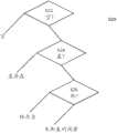
在提取试管顶部块中的托盘狭槽之后,可以经由软件中的检测流水线对其进行处理以将每个托盘狭槽分类为空或非空、将每个非空狭槽分类为具有盖或不具有盖,并且进一步将每个未加盖的试管分类为具有管顶杯或不具有管顶杯。在图7中示出基本决策树。方法620示出用于从图像块表征试管狭槽的内含物的基本过程。在步骤622处,图像处理器观看与试管狭槽对应的托盘级图像块并且确定该块指示狭槽为空还是被占用。如果被占用,则在步骤624处,处理器观看占用狭槽的试管的顶部的试管级块以确定盖是否存在。如果盖不存在,则在步骤626处,图像处理器根据试管级块确定管顶杯是否存在。以该方式,图像处理器使用与狭槽对应的托盘级和试管级块来将每个托盘狭槽分类为“空”和“非空”类别、并且将每个“非空”托盘狭槽分类成“具有盖的试管”、“具有管顶样品杯的试管”以及“光管”种类。After extracting the tray slots in the top block of tubes, they can be processed via an inspection pipeline in the software to classify each tray slot as empty or non-empty, each non-empty slot as having a lid or not Caps were provided, and each uncapped test tube was further classified as either with or without a top cup. A basic decision tree is shown in FIG. 7 .
步骤622处的空托盘狭槽检测包括两个步骤。在第一步骤中,将来自每个输入图像的提取的托盘狭槽块馈送给使用空狭槽块和非空狭槽块训练的随机森林分类器。给定输出分数,将每个块分类成“空”种类(如果分数小于


在一些实施例中,在图像平面中存在三行试管,其在每个图像中被分析。最接近相机的图像中心的中心行包括在抽屉关闭时直接在相机下方的试管。顶部行包括抽屉中的已经滑过相机的试管狭槽,而底部行包括在抽屉关闭时DVS中的还未在相机下方经过的试管狭槽,或者反之亦然。因此,每个试管狭槽在其经过相机时可以被分析三次,从而在试管狭槽的三个连续图像中提供三个分离的相机角度。作为训练过程的部分,并且创建经优化的加权平均,从而允许将权重分配给三个试管狭槽位置中的每个。例如,与中心行中的试管狭槽相关联的图像块可以被给定较高权重,因为该狭槽在图像中的中心位置和基本上垂直的相机视图允许中心行图像块中的试管狭槽相比于顶部或底部行中的图像块而言较不模糊,由于拍摄这些图像块所用的斜角度。在一些实施例中,当优化检测时,可以将不同的权重分配给不同列中的试管狭槽。例如,在中心行中但不直接在相机下面的列中的试管可以由于在试管狭槽处被观察到所用的斜角度而对于相机而言在图像中不同地离开中心出现。通过利用加权平均,可以获得较高的置信水平以用于检测步骤。该加权平均方案可以应用于步骤622、624和626中的每个或本文中讨论的其他处理步骤中的任何处理步骤。In some embodiments, there are three rows of test tubes in the image plane, which are analyzed in each image. The center row closest to the center of the camera's image includes the test tubes directly below the camera when the drawer is closed. The top row includes tube slots in the drawer that have slid past the camera, while the bottom row includes tube slots in the DVS that have not yet passed under the camera when the drawer is closed, or vice versa. Thus, each tube slot can be analyzed three times as it passes the camera, providing three separate camera angles in three consecutive images of the tube slot. As part of the training process, an optimized weighted average is created, allowing weights to be assigned to each of the three tube slot positions. For example, an image patch associated with a tube slot in the center row may be given a higher weight because the slot's central position in the image and the substantially vertical camera view allow for the tube slot in the center row image patch It is less blurry than the image blocks in the top or bottom row, due to the oblique angle at which these image blocks were taken. In some embodiments, different weights may be assigned to tube slots in different columns when optimizing assays. For example, tubes in the center row but not in the column directly below the camera may appear differently from the center in the image for the camera due to the oblique angle at which the tube slot is observed. By utilizing weighted averaging, a higher confidence level can be obtained for the detection step. This weighted averaging scheme may be applied to each of
步骤624可以包括两个步骤。在第一步骤中,将来自每个输入图像的(根据步骤622分类的)提取的“非空”试管顶部块馈送到使用具有盖块和其他块的试管训练的随机森林分类器。给定输出分数,将每个块分类成“具有盖的试管”种类(如果分数小于


类似于空狭槽检测,处理器可以利用基于块位置的试管预测。在方案中,处理器将试管块分类成三个种类使得中心行处的块(我们将在该数据集上训练的分类器称为


在盖检测中针对行中的每个对三个分类器的训练使用随机森林技术。如下在运行时间计算对非空狭槽中的新试管块的预测:The training of the three classifiers for each pair in the row uses a random forest technique in lid detection. Predictions for new tube blocks in non-empty slots are calculated at run time as follows:

下标
步骤626基本上类似于步骤624,这里分类器被训练以检测管顶杯而不是试管盖。Step 626 is substantially similar to step 624, where the classifier is trained to detect tube top cups rather than test tube caps.
图像处理器还可以根据在试管狭槽经过时由相机捕获的图像来估计试管高度。为了估计试管高度,可以使用在试管相对于相机移动时的相同试管的连续图像。一旦校准了相机,就可以利用连续图像之间的试管顶部的图像内的位移来确定试管高度。通过假设相机的观看方向垂直于托盘表面,可以用简单的2-D投影模型来执行试管高度估计。2-D投影的位移与物理位移成正比并且与距相机中心的距离成反比。更正式地,其被通过以下透视投影模型来描述:The image processor can also estimate the tube height from images captured by the camera as the tube slot passes by. To estimate the height of the cuvette, successive images of the same cuvette as the cuvette is moved relative to the camera can be used. Once the camera is calibrated, the displacement within the image of the top of the tube between successive images can be used to determine the tube height. Tube height estimation can be performed with a simple 2-D projection model by assuming that the viewing direction of the camera is normal to the tray surface. The displacement of the 2-D projection is proportional to the physical displacement and inversely proportional to the distance from the camera center. More formally, it is described by the following perspective projection model:

在等式5中,f是焦距,并且Z是3-D点到相机的光心之间的距离,


因此通过跟踪点标记在托盘表面上的位移


由图像处理器进行的图像分析还可以确定对所检测的试管的试管直径的估计。一旦估计了试管高度,就可以基于经校准的相机几何形状来近似每个所检测的试管的直径。通过以下关系使这成为可能。Image analysis by the image processor can also determine an estimate of the tube diameter of the detected tube. Once the tube height is estimated, the diameter of each detected tube can be approximated based on the calibrated camera geometry. This is made possible by the following relationship.

在等式9中,


此外,图像处理器可以估计试管中心偏移,其可能有助于确定试管是否倾斜得更多,以用于确定如果试管狭槽不具有定心弹簧来支持试管,则试管位于试管狭槽中的何处。通过计算3-D中的试管中心和3-D中的托盘狭槽中心之间的偏移来估计试管中心偏移。In addition, the image processor can estimate the tube center offset, which may help determine if the tube is tilted more, for use in determining if the tube is in the tube slot if it does not have a centering spring to support the tube where. Estimate the tube center offset by calculating the offset between the tube center in 3-D and the tray slot center in 3-D.


图像处理器还可以通过执行SVG颜色空间中的颜色分类来估计任何盖的颜色。针对与盖在图像中的地方对应的像素中的每个,处理器将所述像素映射到颜色空间中并且查找集群。在一些实施例中,图像处理器通过使类似颜色的一个集群或两个集群适合在盖圆(cap circle)内来估计盖的颜色。集群的紧凑性用来确定有一个还是两个颜色存在。例如,某些盖具有多个颜色以指示某些内含物类型。The image processor can also estimate the color of any lid by performing color classification in the SVG color space. For each of the pixels corresponding to a place covered in the image, the processor maps the pixel into a color space and finds clusters. In some embodiments, the image processor estimates the color of the cap by fitting a cluster or two clusters of similar colors within a cap circle. The compactness of the cluster is used to determine whether one or two colors are present. For example, some covers have multiple colors to indicate certain types of inclusions.
图8描绘用以创建DVS图像数据库的数据流,其可以用于训练和测试用于DVS的图像处理系统。可以在训练会话之前创建该数据库。这可以在工厂处或在消费者场所处进行。应该使用各种数据测试情况来充分训练DVS系统。托盘类型/方位测试情况(case)702可以包括多个类型的托盘,诸如55位置托盘和15位置托盘,以及这些托盘可能在DVS抽屉中出现的各种方位。狭槽类型测试情况704包括为空的狭槽和包含样品试管的狭槽。流体类型测试情况706包括将在实验室中遭遇的各种样品类型,诸如血清、全血、尿液等。试管几何形状测试情况708包括将在实验室环境中利用的各种试管高度、试管直径和试管材料。测试情况708可以从自定义安装到消费者安装不等,或者所列举的可用试管几何形状的列表可以用来在工厂处训练试管几何形状的超集。试管形状测试情况710包括具有盖、管顶杯的试管和未装饰有盖或杯的演奏(playing)试管。针对具有盖的那些试管,盖颜色测试情况712可以包括单个和多个颜色。在一些实施例中,基于可以在测试情况702到712中选择的期望测试情况,处理器自动地生成对这些测试情况的所有可能组合的列举以使用数据配置生成器714创建训练样品计划。数据配置生成器714的输出是单个数据集配置716,其包括足够的测试实例来训练图像处理器处理测试情况中的每个。在步骤718处,技术员将准备具有与由处理器确定的数据集配置716一致的各种试管和流体的托盘。这些样品托盘然后通过作为消费者仪器的部分的DVS系统或DVS测试装具来准备与数据集716一致的多个测试图像。数据库720包括每个测试样品的地面实况,从而允许训练。8 depicts a data flow to create a DVS image database, which can be used to train and test an image processing system for DVS. This database can be created before a training session. This can be done at the factory or at the consumer site. The DVS system should be adequately trained using various data test situations. Tray Type/
图9描绘用以使用DVS测试装具或DVS来创建DVS图像数据库数据的数据创建过程。一旦包括规定的测试情况场景的物理测试托盘被加载到DVS中,DVS就在步骤722处检测托盘方位。这可以经由用以检测角的存在的光学装置或通过检测插入到抽屉中的托盘的物理方位的物理装置进行。在步骤724处,检测在每个样品托盘的边缘处的条形码。这允许DVS处理器确定托盘类型,诸如图像将对应的55狭槽托盘。在步骤726处,检测托盘表面上的基准标记。这允许DVS处理器定向样品托盘的突出组件的物理位置。在步骤728处,处理器生成可以虚拟地覆盖到样品托盘的图像上的虚拟狭槽网格。该网格考虑两个DVS相机的相机校准数据。在步骤730处,处理器提取狭槽块,如本文中描述的那样通过标识狭槽相对于基准标志的位置。与那些狭槽对应的图像块变成可以被插入到DVS图像数据库720中的训练数据。具体地,训练数据是空比对非空数据库732,因为通过步骤730生成的来自所捕获的各种图像的狭槽块包括可以用于训练目的空和非空狭槽两者。在步骤734处,图像处理器生成试管顶层块提取区域。该提取区域可以是粗略地与每个狭槽的位置相关并且允许在该提取区域内标识试管顶部的搜索区域。在步骤736处,在提取区域内运行圆检测算法以标识每个试管顶部的图像内的精确位置。在步骤738处,标识在提取区域内的试管顶部圆。在步骤740处,图像处理器提取以所检测的图像顶部圆为中心的试管顶部块。这些块还可以被标准化成使得块的范围与试管顶部圆的范围相关。该处理导致两个数据库,盖比对无盖数据库742和杯对对平面试管数据库744,因为图像中的试管应该包括杯、盖和未加盖的样品。数据库742和744成为DVS图像数据库720的部分。以该方式,可以使用DVS测试装具或DVS系统来创建图像块的完整训练集。9 depicts a data creation process to create DVS image database data using a DVS test fixture or DVS. Once the physical test tray including the specified test situation scenario is loaded into the DVS, the DVS detects the tray orientation at step 722 . This can be done via optical means to detect the presence of the angle or by physical means to detect the physical orientation of the tray inserted into the drawer. At step 724, barcodes are detected at the edges of each sample tray. This allows the DVS processor to determine the tray type, such as the 55-slot tray to which the image will correspond. At step 726, fiducial marks on the surface of the tray are detected. This allows the DVS processor to orient the physical location of the protruding components of the sample tray. At step 728, the processor generates a virtual slot grid that can be virtually overlaid onto the image of the sample tray. This grid takes into account the camera calibration data of the two DVS cameras. At step 730, the processor extracts the slot block, as described herein, by identifying the position of the slot relative to the fiducial markers. Image patches corresponding to those slots become training data that can be inserted into the DVS image database 720 . Specifically, the training data is the empty vs. non-empty database 732, since the slot blocks from the various captured images generated by step 730 include both empty and non-empty slots that can be used for training purposes. At step 734, the image processor generates a cuvette top block extraction region. The extraction area may be a search area that correlates roughly with the location of each slot and allows the top of the test tube to be identified within the extraction area. At step 736, a circle detection algorithm is run within the extraction region to identify the precise location within the image of the top of each test tube. At step 738, the tube top circle within the extraction area is identified. At step 740, the image processor extracts the test tube top block centered on the detected image top circle. The blocks can also be normalized so that the extent of the block is related to the extent of the circle at the top of the tube. This process results in two databases, a lid vs. uncovered database 742 and a cup vs. flat tube database 744, since the tubes in the image should include cups, lids, and uncapped samples. Databases 742 and 744 become part of DVS image database 720. In this way, a DVS test rig or DVS system can be used to create a complete training set of image patches.
图10描绘用于训练分类器以便检测图7中的任何状况的训练过程750。针对每个分类器创建训练数据的两个集合。积极训练数据752包含其中被分类的状况是积极的图像块,诸如具有盖的试管;消极训练数据753包含其中被分类的状况是消极的图像块,诸如缺少盖的试管。通过由处理器操作的处理器754生成分类器参数。这些参数可以是用于训练分类器的适当参数的最佳猜测起点并且导致参数集756。参数集756中的参数可以包括用来配置随机森林分类训练算法的参数,其诸如标识树的深度为10、叶特征(note)处的最小样品计数为5、活动变量的数量为100以及树的最大数量为100。参数还可以包括


图11示出用于利用校准目标(诸如图5中示出的校准目标)来校准相机的示例性方法700。使用先前校准的高分辨率相机,从DVS中的每个获取校准目标的多个图像772。这些图像包括目标的多个放置以提供充分的数据来估计标记在校准目标上的3-D坐标。在步骤774处,校准处理器估计校准目标的板与图像中的像素值之间的刚性变换。这导致在3-D空间中标识目标上的每个标记的角的3-D坐标776并且提供可以在等式1中使用的校准目标的3-D模型。一旦标记的3-D模型可用,被校准的DVS中的相机就可以捕获安装在托盘上并且插入在DVS抽屉中的校准目标的多个图像778。在步骤780处,校准处理器利用要被校准的DVS的图像778和3-D坐标776来校准抽屉的每个DVS相机。该步骤可以利用在本文中讨论的教导,诸如等式1。在步骤782处,校准处理器使用在本文中讨论的方法(诸如等式2和3)来计算DVS抽屉中的两个相机之间的相对姿态。这导致用于DVS系统中的每个相机的校准参数784。这允许训练DVS系统并且补偿相机伪像。FIG. 11 illustrates an
图12示出用于在运行时间操作抽屉视觉系统以处理来自抽屉视觉系统的图像并且表征样品托盘的内含物的示例性软件数据流800。图像802包含当插入抽屉时被抽屉视觉系统捕获的图像。这些图像可以包括当抽屉完全关闭或部分打开时抽屉中的样品托盘的部分的图像。软件模块804检测抽屉的内含物的托盘方位,如本文中讨论的那样。软件模块806检测样品托盘的表面上的条形码。这允许软件在步骤810处确定托盘类型和/或托盘的身份。软件模块812提供标记检测,从而标识托盘的表面上的基准标志(诸如白点)的位置。软件模块814基于这些基准标志的位置而将狭槽网络生成到图像上,如以上讨论的那样。模块814利用相机校准数据816来补偿捕获包含基准标志的图像的相机的光学性质。12 illustrates an exemplary
软件模块816基于图像的网格覆盖提取与狭槽对应的图像块以确定图像中的狭槽的位置。这些狭槽图像块被提供给检测模块818的空狭槽。检测模块818利用先前已经被训练的空狭槽检测分类器820。利用与每个托盘狭槽对应的图像块以及检测分类器820 ,检测模块818确定每个狭槽是否为空。如果狭槽被确定为空,则这导致空狭槽预测822,从而允许将狭槽被分类为空。软件模块824生成图像中的试管顶层块提取区域以约束对图像中的试管的顶部的搜索。在一些实施例中,模块824仅针对与非空狭槽对应的每个区域执行。软件模块826提供针对每个试管顶层提取区域的试管顶部检测。为了完成该任务,模块826执行步骤828以检测提取区域中的圆的存在,其与试管的顶部对应。软件模块830提取由模块826标识的试管顶部块,从而允许包含与试管的顶部对应的圆的图像块被进一步检查。The software module 816 extracts image patches corresponding to the slots based on the grid overlay of the images to determine the positions of the slots in the image. These slot image patches are provided to the empty slots of
软件模块832通过检查由模块830提供的试管顶部块以及利用先前已经训练的盖提取分类器834来提供盖检测。如果盖检测模块832检测到盖,则这导致盖的存在的预测836。如果否,则软件模块838通过利用管顶杯检测分类器840分析试管顶部块来提供管顶杯检测,所述管顶杯检测分类器840可以如先前讨论的那样被训练。模块838的操作的结果是试管可以被标识为具有预测的杯(数据结构842)或被预测是光管(数据结构844)。软件模块846通过分析图像来提供如先前讨论的试管几何形状估计以标识高度估计、直径估计和中心偏移估计。软件模块848可以提供对托盘和试管的合计分析,从而标识特点清单。这可以包括:托盘ID的标识,其可以由条形码检测模块806提供;托盘的方位,其可以由托盘方位模块804提供;狭槽类型,其可以由数据结构822提供;试管类型,其可以由数据结构836、842和844提供;以及试管几何形状,其可以由试管几何形状估计模块846提供。
本发明的实施例可以与现有分析仪和自动化系统集成。应该领会到,可以以许多形状和大小来配置承载器,包括适合于供任何设想的分析仪或仪器使用的布局和物理配置。例如,在一些实施例中,承载器可以包括用于承载自动化轨道周围的多个样品的多个狭槽。一个实施例例如可以包括在一个或多个运输支架中具有多个狭槽的承载器的试管支持部分的物理布局。每个支架可以包括多个狭槽(例如,五或更多狭槽),每个狭槽被配置成支持试管(例如,样品试管)。Embodiments of the present invention can be integrated with existing analyzers and automation systems. It should be appreciated that the carrier may be configured in many shapes and sizes, including layouts and physical configurations suitable for use with any contemplated analyzer or instrument. For example, in some embodiments, the carrier may include multiple slots for carrying multiple samples around the automated track. An embodiment may include, for example, the physical layout of the cuvette support portion of the carrier having multiple slots in one or more shipping racks. Each rack may include a plurality of slots (eg, five or more slots), each slot configured to support a test tube (eg, a sample test tube).
尽管已经参考示例性实施例描述了本发明,但本发明不限于此。本领域技术人员将领会到,可以对本发明的优选实施例进行许多改变和修改并且可以进行这样的改变和修改而不脱离本发明的真实精神。因此意图是将所附权利要求解释为覆盖如落入本发明的真实精神和范围内的所有这样的等同变化。Although the present invention has been described with reference to the exemplary embodiments, the present invention is not limited thereto. Those skilled in the art will appreciate that many changes and modifications can be made to the preferred embodiments of the present invention and that such changes and modifications can be made without departing from the true spirit of the invention. It is therefore intended that the appended claims be construed to cover all such equivalent changes as fall within the true spirit and scope of the invention.
Claims (20)
Applications Claiming Priority (3)
| Application Number | Priority Date | Filing Date | Title |
|---|---|---|---|
| US201462010370P | 2014-06-10 | 2014-06-10 | |
| US62/010370 | 2014-06-10 | ||
| PCT/US2015/035092WO2015191702A1 (en) | 2014-06-10 | 2015-06-10 | Drawer vision system |
Publications (2)
| Publication Number | Publication Date |
|---|---|
| CN107003124A CN107003124A (en) | 2017-08-01 |
| CN107003124Btrue CN107003124B (en) | 2020-07-07 |
Family
ID=54834240
Family Applications (1)
| Application Number | Title | Priority Date | Filing Date |
|---|---|---|---|
| CN201580039713.1AActiveCN107003124B (en) | 2014-06-10 | 2015-06-10 | Drawer Vision System |
Country Status (5)
| Country | Link |
|---|---|
| US (1) | US10140705B2 (en) |
| EP (1) | EP3155368B1 (en) |
| CN (1) | CN107003124B (en) |
| CA (1) | CA2950296C (en) |
| WO (1) | WO2015191702A1 (en) |
Families Citing this family (38)
| Publication number | Priority date | Publication date | Assignee | Title |
|---|---|---|---|---|
| EP3259068B1 (en) | 2015-02-17 | 2023-03-29 | Siemens Healthcare Diagnostics Inc. | Detection of barcode tag conditions on sample tubes |
| US10319092B2 (en) | 2015-02-18 | 2019-06-11 | Siemens Healthcare Diagnostics Inc. | Locality-based detection of tray slot types and tube types in a vision system |
| CN108885781B (en)* | 2015-04-28 | 2022-07-08 | 西门子保健有限责任公司 | Method and system for synthesizing virtual high dose or high kV computed tomography images from low dose or low kV computed tomography images |
| WO2018013345A1 (en)* | 2016-07-14 | 2018-01-18 | Siemens Healthcare Diagnostics Inc. | Methods and apparatus for dynamic position adjustments of a robot gripper based on sample rack imaging data |
| US11209447B2 (en) | 2016-07-14 | 2021-12-28 | Siemens Healthcare Diagnostics Inc. | Methods, systems, and apparatus for dynamic pick and place selection sequence based on sample rack imaging data |
| US11378583B2 (en) | 2016-07-21 | 2022-07-05 | Siemens Healthcare Diagnostics Inc. | Automated clinical analyzer system and method |
| RU2762936C2 (en) | 2016-10-28 | 2021-12-24 | Бекман Каултер, Инк. | System for assessing substance preparation |
| EP3357842B1 (en) | 2017-02-03 | 2022-03-23 | Roche Diagnostics GmbH | Laboratory automation system |
| CN110832508B (en) | 2017-07-11 | 2023-08-11 | 美国西门子医学诊断股份有限公司 | Method and system for learning-based image edge enhancement for sample tube top-rounding |
| JP7087058B2 (en)* | 2017-07-11 | 2022-06-20 | シーメンス・ヘルスケア・ダイアグノスティックス・インコーポレーテッド | Image-based tube head circle detection using multiple candidates |
| US11574460B2 (en) | 2017-10-27 | 2023-02-07 | Beckman Coulter, Inc. | Sample container recognition |
| ES2956287T3 (en)* | 2018-03-30 | 2023-12-18 | Amgen Inc | Inspection of drug containers using cameras |
| CN108983306B (en)* | 2018-06-06 | 2019-11-19 | 浙江大华技术股份有限公司 | A kind of method and rays safety detection apparatus of article frame flow display |
| JP6981448B2 (en)* | 2018-06-08 | 2021-12-15 | オムロン株式会社 | Controllers, controller control methods, learning devices, and programs |
| JP7320972B2 (en)* | 2019-04-08 | 2023-08-04 | 株式会社日立ハイテク | Image processing device, automatic analysis system and image processing method |
| CN112072634B (en)* | 2019-06-10 | 2022-06-24 | 浙大城市学院 | Load flow calculation method based on load flow embedding technology |
| EP3789772B1 (en)* | 2019-09-05 | 2025-03-26 | Roche Diagnostics GmbH | Method for determining a position of a rack on a rack placement unit of a laboratory handling system and laboratory handling system |
| KR102782480B1 (en)* | 2019-09-17 | 2025-03-19 | 베크만 컬터, 인코포레이티드 | Automated reagent identification for fluid handling systems |
| EP4052461A4 (en) | 2019-10-31 | 2023-04-19 | Siemens Healthcare Diagnostics, Inc. | Methods and apparatus providing calibration of background illumination for sample and/or sample container characterization |
| CN114585443B (en)* | 2019-10-31 | 2023-11-03 | 美国西门子医学诊断股份有限公司 | Apparatus and method for training diagnostic analyzer model |
| JP7462039B2 (en)* | 2019-10-31 | 2024-04-04 | シーメンス・ヘルスケア・ダイアグノスティックス・インコーポレイテッド | Method and apparatus for providing foreground illumination calibration for characterizing sample containers - Patents.com |
| EP3839515A1 (en) | 2019-12-18 | 2021-06-23 | Roche Diagnostics GmbH | Method and devices for assessing the suitability of a sample tube for use in a laboratory automation system |
| EP4100874B1 (en)* | 2020-02-06 | 2025-07-30 | Berkshire Grey Operating Company, Inc. | Systems and methods for camera calibration with a fiducial of unknown position on an articulated arm of a programmable motion device |
| JP7313310B2 (en) | 2020-03-31 | 2023-07-24 | 日本碍子株式会社 | Inspection method and inspection apparatus for columnar honeycomb structure made of ceramics |
| CN111986263B (en)* | 2020-06-28 | 2023-09-12 | 百度在线网络技术(北京)有限公司 | Image processing method, device, electronic equipment and storage medium |
| EP3968027A1 (en)* | 2020-09-14 | 2022-03-16 | Eppendorf AG | Method and device for identifying labware |
| US12272046B2 (en)* | 2020-09-21 | 2025-04-08 | International Business Machines Corporation | Feature detection based on neural networks |
| EP3979131A1 (en) | 2020-10-02 | 2022-04-06 | Roche Diagnostics GmbH | A method for determining at least one state of at least one cavity of a transport interface configured for transporting sample tubes |
| JP7163947B2 (en)* | 2020-10-22 | 2022-11-01 | セイコーエプソン株式会社 | Projection area setting support method, setting support system, and program |
| JP7617295B2 (en)* | 2021-02-11 | 2025-01-17 | シーメンス・ヘルスケア・ダイアグノスティックス・インコーポレイテッド | Method and apparatus adapted to identify the 3D center position of a specimen container using a single image capture device - Patents.com |
| CA3235375A1 (en)* | 2021-10-18 | 2023-04-27 | Mark Andrews | Inspection unit for cans and method for determining the quality of cans |
| WO2023088600A1 (en) | 2021-11-22 | 2023-05-25 | Roche Diagnostics Gmbh | Method and system for operating a laboratory automation system |
| TWI799012B (en)* | 2021-12-17 | 2023-04-11 | 王一互動科技有限公司 | Electronic apparatus and method for presenting three-dimensional space model |
| EP4231019B1 (en)* | 2022-02-17 | 2024-12-18 | Roche Diagnostics GmbH | Laboratory system |
| JP7724380B2 (en) | 2022-03-03 | 2025-08-15 | シーメンス・ヘルスケア・ダイアグノスティックス・インコーポレイテッド | Diagnostic laboratory system and method for imaging a tube assembly - Patent Application 20070122997 |
| WO2023225123A1 (en)* | 2022-05-18 | 2023-11-23 | Siemens Healthcare Diagnostics Inc. | Sample handlers of diagnostic laboratory analyzers and methods of use |
| US12309352B2 (en) | 2022-06-30 | 2025-05-20 | Apple Inc. | In-field calibration techniques for cameras |
| US11877071B1 (en) | 2022-09-22 | 2024-01-16 | Apple Inc. | Flicker and proximity detection in image sensors with embedded low power readout circuitry |
Family Cites Families (16)
| Publication number | Priority date | Publication date | Assignee | Title |
|---|---|---|---|---|
| KR100704324B1 (en)* | 1998-05-01 | 2007-04-09 | 젠-프로브 인코포레이티드 | Automated Analytical Instruments and Automated Analytical Methods |
| US20040252299A9 (en)* | 2000-01-07 | 2004-12-16 | Lemmo Anthony V. | Apparatus and method for high-throughput preparation and spectroscopic classification and characterization of compositions |
| US20050169733A1 (en)* | 2004-01-29 | 2005-08-04 | Drynkin Alexander V. | Automated tube handler system |
| US20060000296A1 (en)* | 2004-07-02 | 2006-01-05 | Salter Jason P | Synchronization of sample and data collection |
| US7499581B2 (en)* | 2005-02-10 | 2009-03-03 | Forhealth Technologies, Inc. | Vision system to calculate a fluid volume in a container |
| US7988933B2 (en)* | 2006-09-01 | 2011-08-02 | Siemens Healthcare Diagnostics Inc. | Identification system for a clinical sample container |
| US20090154764A1 (en)* | 2006-10-20 | 2009-06-18 | Forhealth Technologies, Inc. | Drug vial detection in an automated drug preparation system |
| EP2227774B1 (en) | 2007-12-04 | 2014-07-09 | University College Dublin, National University of Ireland Dublin | Method and system for image analysis |
| US8170271B2 (en)* | 2008-06-25 | 2012-05-01 | Jadak Llc | System and method for test tube and cap identification |
| US11865534B2 (en) | 2008-09-24 | 2024-01-09 | First Light Diagnostics, Inc. | Imaging analyzer for testing analytes |
| DE102011005807B4 (en) | 2011-03-18 | 2017-02-16 | Anton Paar Gmbh | Cuvette and optical measuring device |
| EP2734824B1 (en)* | 2011-07-22 | 2019-01-23 | Roche Diagnostics Hematology, Inc. | Fluid sample preparation systems and methods |
| US20160109406A1 (en)* | 2012-03-15 | 2016-04-21 | Advanced Analytical Technologies, LLC | Pulse-field multiplex capillary electrophoresis system |
| US9135515B2 (en) | 2012-10-22 | 2015-09-15 | Qiagen Gaithersburg, Inc. | Automated pelletized sample vision inspection apparatus and methods |
| HU230739B1 (en)* | 2013-02-28 | 2018-01-29 | 3Dhistech Kft. | Apparatus and method for automatic staining masking, digitizing of slides |
| US10145857B2 (en)* | 2013-03-14 | 2018-12-04 | Siemens Healthcare Diagnostics Inc. | Tube tray vision system |
- 2015
- 2015-06-10WOPCT/US2015/035092patent/WO2015191702A1/enactiveApplication Filing
- 2015-06-10CACA2950296Apatent/CA2950296C/enactiveActive
- 2015-06-10CNCN201580039713.1Apatent/CN107003124B/enactiveActive
- 2015-06-10USUS15/317,497patent/US10140705B2/enactiveActive
- 2015-06-10EPEP15806102.8Apatent/EP3155368B1/enactiveActive
Also Published As
| Publication number | Publication date |
|---|---|
| EP3155368B1 (en) | 2020-07-29 |
| CN107003124A (en) | 2017-08-01 |
| EP3155368A1 (en) | 2017-04-19 |
| EP3155368A4 (en) | 2017-06-21 |
| US10140705B2 (en) | 2018-11-27 |
| WO2015191702A1 (en) | 2015-12-17 |
| CA2950296C (en) | 2022-12-13 |
| CA2950296A1 (en) | 2015-12-17 |
| US20170124704A1 (en) | 2017-05-04 |
Similar Documents
| Publication | Publication Date | Title |
|---|---|---|
| CN107003124B (en) | Drawer Vision System | |
| JP6870826B2 (en) | Methods and devices configured to quantify samples from lateral multi-viewpoints | |
| EP3408641B1 (en) | Methods and apparatus for multi-view characterization | |
| US10145857B2 (en) | Tube tray vision system | |
| JP6800223B2 (en) | Material preparation evaluation system | |
| US10928310B2 (en) | Methods and apparatus for imaging a specimen container and/or specimen using multiple exposures | |
| CN107532125B (en) | Image-based pipe chase circular detection for vision systems | |
| JP7012719B2 (en) | Methods and equipment for characterizing samples using pattern illumination | |
| US20240133908A1 (en) | Methods and apparatus adapted to identify 3d center location of a specimen container using a single image capture device | |
| US20250271454A1 (en) | Sample handlers of diagnostic laboratory analyzers and methods of use | |
| CN114600131A (en) | Method and apparatus for automated specimen characterization using a diagnostic analysis system with continuous performance-based training | |
| US20240230695A9 (en) | Apparatus and methods of aligning components of diagnostic laboratory systems | |
| CN119563193A (en) | Apparatus and method for training sample characterization algorithms in diagnostic laboratory systems | |
| HK1235856B (en) | Drawer vision system | |
| HK1235856A1 (en) | Drawer vision system | |
| HK1242727A1 (en) | Image-based tube slot circle detection for a vision system | |
| HK1255411B (en) | Methods and apparatus adapted to quantify a specimen from multiple lateral views |
Legal Events
| Date | Code | Title | Description |
|---|---|---|---|
| PB01 | Publication | ||
| PB01 | Publication | ||
| SE01 | Entry into force of request for substantive examination | ||
| SE01 | Entry into force of request for substantive examination | ||
| REG | Reference to a national code | Ref country code:HK Ref legal event code:DE Ref document number:1235856 Country of ref document:HK | |
| GR01 | Patent grant | ||
| GR01 | Patent grant |