CN106993322B - Electronic device and communication method - Google Patents
Electronic device and communication methodDownload PDFInfo
- Publication number
- CN106993322B CN106993322BCN201610040661.6ACN201610040661ACN106993322BCN 106993322 BCN106993322 BCN 106993322BCN 201610040661 ACN201610040661 ACN 201610040661ACN 106993322 BCN106993322 BCN 106993322B
- Authority
- CN
- China
- Prior art keywords
- access point
- cooperative
- distribution center
- data distribution
- user equipment
- Prior art date
- Legal status (The legal status is an assumption and is not a legal conclusion. Google has not performed a legal analysis and makes no representation as to the accuracy of the status listed.)
- Active
Links
Images


Classifications
- H—ELECTRICITY
- H04—ELECTRIC COMMUNICATION TECHNIQUE
- H04W—WIRELESS COMMUNICATION NETWORKS
- H04W40/00—Communication routing or communication path finding
- H04W40/02—Communication route or path selection, e.g. power-based or shortest path routing
- H04W40/22—Communication route or path selection, e.g. power-based or shortest path routing using selective relaying for reaching a BTS [Base Transceiver Station] or an access point
- G—PHYSICS
- G06—COMPUTING OR CALCULATING; COUNTING
- G06F—ELECTRIC DIGITAL DATA PROCESSING
- G06F1/00—Details not covered by groups G06F3/00 - G06F13/00 and G06F21/00
- G06F1/16—Constructional details or arrangements
- G06F1/1613—Constructional details or arrangements for portable computers
- G06F1/1633—Constructional details or arrangements of portable computers not specific to the type of enclosures covered by groups G06F1/1615 - G06F1/1626
- G06F1/1684—Constructional details or arrangements related to integrated I/O peripherals not covered by groups G06F1/1635 - G06F1/1675
- G06F1/1698—Constructional details or arrangements related to integrated I/O peripherals not covered by groups G06F1/1635 - G06F1/1675 the I/O peripheral being a sending/receiving arrangement to establish a cordless communication link, e.g. radio or infrared link, integrated cellular phone
- H—ELECTRICITY
- H04—ELECTRIC COMMUNICATION TECHNIQUE
- H04W—WIRELESS COMMUNICATION NETWORKS
- H04W24/00—Supervisory, monitoring or testing arrangements
- H04W24/08—Testing, supervising or monitoring using real traffic
- H—ELECTRICITY
- H04—ELECTRIC COMMUNICATION TECHNIQUE
- H04W—WIRELESS COMMUNICATION NETWORKS
- H04W40/00—Communication routing or communication path finding
- H04W40/02—Communication route or path selection, e.g. power-based or shortest path routing
- H04W40/18—Communication route or path selection, e.g. power-based or shortest path routing based on predicted events
- H—ELECTRICITY
- H04—ELECTRIC COMMUNICATION TECHNIQUE
- H04W—WIRELESS COMMUNICATION NETWORKS
- H04W48/00—Access restriction; Network selection; Access point selection
- H04W48/20—Selecting an access point
- H—ELECTRICITY
- H04—ELECTRIC COMMUNICATION TECHNIQUE
- H04W—WIRELESS COMMUNICATION NETWORKS
- H04W88/00—Devices specially adapted for wireless communication networks, e.g. terminals, base stations or access point devices
- H04W88/02—Terminal devices
- H04W88/06—Terminal devices adapted for operation in multiple networks or having at least two operational modes, e.g. multi-mode terminals
Landscapes
- Engineering & Computer Science (AREA)
- Computer Networks & Wireless Communication (AREA)
- Signal Processing (AREA)
- Computer Hardware Design (AREA)
- General Engineering & Computer Science (AREA)
- Theoretical Computer Science (AREA)
- Human Computer Interaction (AREA)
- Physics & Mathematics (AREA)
- General Physics & Mathematics (AREA)
- Computer Security & Cryptography (AREA)
- Mobile Radio Communication Systems (AREA)
Abstract
Description
Translated fromChinese技术领域technical field
本发明涉及电子设备和通信方法,更具体地,本公开涉及协作传输系统的电子设备和通信方法。The present invention relates to an electronic device and a communication method, and more particularly, the present disclosure relates to an electronic device and a communication method of a cooperative transmission system.
背景技术Background technique
在新的服务、应用和设备驱使下,未来无线通信中的数据流量正在爆发式地增长。已经公开了一种以用户设备为中心的网络,其包括用户设备、多个接入点和一个服务网关,其中,用户设备不属于通信系统中的任何一个接入点,并且会自主选择一个接入点来为其提供服务,例如,见学术论文“Routing in user-centric networks”,X.Xing,T.Jing,W.Zhou,X.Cheng,Y.Huo和H.Liu,IEEE Commun.Mag.,vol.52,no.9,pp.44-51,Sep.2014。该学术论文考虑了“不总是存在从信息源到其目的地的完整稳定路径”的情况并试图寻找合适的中继并形成合适的路由路径。实际上,该学术论文的核心思想是用户设备可以被当做中继来构造传输路径。然而,该学术论文中提出的多个算法,例如,“利用人类社交特性”,在当前网络中实际上是不可实行的。Driven by new services, applications and devices, the data traffic in future wireless communication is growing explosively. A user equipment-centric network has been disclosed, which includes user equipment, multiple access points and a serving gateway, wherein the user equipment does not belong to any access point in the communication system, and will autonomously select an access point. Entry point to provide services for it, for example, see the academic paper "Routing in user-centric networks", X.Xing, T.Jing, W.Zhou, X.Cheng, Y.Huo and H.Liu, IEEE Commun.Mag ., vol.52, no.9, pp.44-51, Sep.2014. This academic paper considers the case that "there is not always a complete stable path from the source of the information to its destination" and tries to find a suitable relay and form a suitable routing path. In fact, the core idea of this academic paper is that the user equipment can be used as a relay to construct a transmission path. However, several of the algorithms proposed in this academic paper, for example, "exploiting human social characteristics", are practically infeasible in current networks.
另外,在传统的蜂窝小区中,为了提高小区边缘处的用户设备的服务质量,已经提出了一种多点协作传输技术(CoMP:Coordinated Multiple Points Transmission/Reception)。在CoMP技术中,对于小区边缘处的用户设备,可以通过联合传输(JT:JointTransmission)实现多个基站同时为边缘用户设备服务。在对该用户设备进行CoMP时,由该用户设备所属的接入点决定是否对其进行CoMP,如果决定对该用户设备进行CoMP,则接入点上报服务网关,通知相邻接入点进行联合传输。在传输过程中,服务网关将以该用户设备为目的地的数据发送给各个接入点,并由接入点向用户设备协同传输数据。In addition, in a traditional cell, in order to improve the service quality of the user equipment at the cell edge, a coordinated multiple point transmission (CoMP: Coordinated Multiple Points Transmission/Reception) technology has been proposed. In the CoMP technology, for the user equipment at the cell edge, multiple base stations can simultaneously serve the edge user equipment through joint transmission (JT: JointTransmission). When performing CoMP on the user equipment, the access point to which the user equipment belongs decides whether to perform CoMP on the user equipment. If it decides to perform CoMP on the user equipment, the access point reports to the serving gateway and notifies the adjacent access points to join forces transmission. During the transmission process, the serving gateway sends the data destined for the user equipment to each access point, and the access points coordinately transmit the data to the user equipment.
发明内容SUMMARY OF THE INVENTION
在现有技术的以用户为中心的网络中,希望能够改善用户设备的通信质量,而在现有技术的CoMP技术中,希望能够改善用户设备的通信效率。In the user-centric network of the prior art, it is desired to improve the communication quality of the user equipment, while in the CoMP technology of the prior art, it is desired to improve the communication efficiency of the user equipment.
鉴于以上内容,希望提供一种改善用户设备的通信质量和通信效率的技术方案。In view of the above, it is desirable to provide a technical solution for improving the communication quality and communication efficiency of user equipment.
本公开的一个方面涉及一种电子设备,包括:处理电路,其被配置为:从多个可用接入点中选择一个或多个可用接入点作为一个或多个协作接入点以及选择一个可用接入点作为数据分发中心,将关于所述一个或多个协作接入点的信息发送给数据分发中心,使得数据分发中心响应于接收到来自于服务网关的以电子设备为目的地的数据,将所述以电子设备为目的地的数据发送给所述一个或多个协作接入点,并且在接收所述以电子设备为目的地的数据时,通过数据分发中心和所述一个或多个协作接入点的协作传输来接收所述以电子设备为目的地的数据。One aspect of the present disclosure relates to an electronic device including: processing circuitry configured to: select one or more available access points from a plurality of available access points as one or more cooperating access points and select one using the access point as a data distribution center, sending information about the one or more cooperating access points to the data distribution center so that the data distribution center is responsive to receiving data from the serving gateway destined for the electronic device , sending the data destined for the electronic device to the one or more cooperative access points, and when receiving the data destined for the electronic device, through the data distribution center and the one or more cooperating access points Cooperative transmission of two cooperating access points to receive the data destined for the electronic device.
本公开的一个方面涉及一种电子设备,包括处理电路,被配置为:在电子设备被用户设备选择作为数据分发中心的情况下,将关于用户设备和数据分发中心的信息发送给服务网关,从用户设备接收关于协作接入点的信息,响应于从服务网关接收到以用户设备为目的地的数据,将所述以用户设备为目的地的数据发送给用户设备和协作接入点,使得通过数据分发中心和协作接入点的协作传输向所述用户设备发送所述以用户设备为目的地的数据;和在电子设备被用户设备选择作为协作接入点的情况下,响应于接收到所述以用户设备为目的地的数据,将所述以用户设备为目的地的数据发送给用户设备,使得通过数据分发中心和协作接入点的协作传输向所述用户设备发送所述以用户设备为目的地的数据。One aspect of the present disclosure relates to an electronic device including a processing circuit configured to: in the event that the electronic device is selected by the user equipment as a data distribution center, send information about the user equipment and the data distribution center to a serving gateway, from The user equipment receives information about the cooperating access point, and in response to receiving data destined for the user equipment from the serving gateway, transmits the data destined to the user equipment to the user equipment and the cooperating access point, so that through The cooperative transmission of the data distribution center and the cooperating access point sends the data destined for the user equipment to the user equipment; and in the case where the electronic device is selected by the user equipment as the cooperating access point, in response to receiving the data The data destined for the user equipment is sent to the user equipment, so that the data destined for the user equipment is sent to the user equipment through cooperative transmission between the data distribution center and the cooperative access point. data for the destination.
本公开的一个方面涉及一种通信方法,包括:由用户设备从多个可用接入点中选择一个或多个可用接入点作为一个或多个协作接入点以及选择一个可用接入点作为数据分发中心,由用户设备将关于所述一个或多个协作接入点的信息发送给数据分发中心,使得数据分发中心响应于接收到来自于服务网关的以用户设备为目的地的数据,将所述以用户设备为目的地的数据发送给所述一个或多个协作接入点,和在用户设备接收所述以用户设备为目的地的数据时,通过数据分发中心和所述一个或多个协作接入点的协作传输来接收所述以用户设备为目的地的数据。One aspect of the present disclosure relates to a communication method, comprising: selecting, by a user equipment, one or more available access points from a plurality of available access points as one or more cooperative access points and selecting one available access point as a The data distribution center, the user equipment sends the information about the one or more cooperative access points to the data distribution center, so that the data distribution center responds to receiving the data destined for the user equipment from the serving gateway, and sends the data to the data distribution center. The data destined for the user equipment is sent to the one or more cooperative access points, and when the user equipment receives the data destined for the user equipment, the data distribution center and the one or more Cooperative transmission of two cooperating access points to receive the data destined for the user equipment.
本公开的一个方面涉及一种通信方法,包括:在接入点被用户设备选择作为数据分发中心的情况下,由数据分发中心将关于用户设备和数据分发中心的信息发送给服务网关,由数据分发中心从用户设备接收关于协作接入点的信息,响应于由数据分发中心从服务网关接收到以用户设备为目的地的数据,由数据分发中心将所述以用户设备为目的地的数据发送给用户设备和协作接入点,使得由数据分发中心和协作接入点的协作传输向用户设备发送所述以用户设备为目的地的数据;和在接入点被用户设备选择作为协作接入点的情况下,响应于由协作接入点接收到所述以用户设备为目的地的数据,由协作接入点将所述以用户设备为目的地的数据发送给用户设备,使得通过数据分发中心和协作接入点的协作传输向用户设备发送所述以用户设备为目的地的数据。One aspect of the present disclosure relates to a communication method, comprising: when an access point is selected by a user equipment as a data distribution center, the data distribution center sends information about the user equipment and the data distribution center to a service gateway, and the data distribution center sends information about the user equipment and the data distribution center to a service gateway; The distribution center receives information about the cooperating access point from the user equipment, and in response to the data distribution center receiving data destined for the user equipment from the serving gateway, the data distribution center sends the data destined to the user equipment to the user equipment and the cooperative access point so that the data destined for the user equipment is sent to the user equipment by the cooperative transmission of the data distribution center and the cooperative access point; and the access point is selected by the user equipment as the cooperative access point In the case of the user equipment, in response to receiving the data destined for the user equipment by the cooperative access point, the cooperative access point transmits the data destined for the user equipment to the user equipment, so that through the data distribution The cooperative transmission of the center and the cooperative access point sends the data destined for the user equipment to the user equipment.
在本公开的实施例中,由用户设备来确定为其提供服务的接入点的协作传输架构,从而能够提高用户设备的通信质量。另外,在本公开的实施例中,服务网关只要将该用户设备的数据传输到该数据分发中心,由数据分发中心来将数据分发给其他协作接入点,因此,服务网关不必重复将数据传输到其他协作接入点,提高了用户设备的通信效率。In the embodiment of the present disclosure, the user equipment determines the cooperative transmission architecture of the access point that provides the service, so that the communication quality of the user equipment can be improved. In addition, in the embodiment of the present disclosure, the service gateway only needs to transmit the data of the user equipment to the data distribution center, and the data distribution center distributes the data to other cooperative access points. Therefore, the service gateway does not need to repeatedly transmit the data. To other cooperative access points, the communication efficiency of the user equipment is improved.
附图说明Description of drawings
图1是根据本公开的实施例的以用户设备为中心的协作传输系统的示例。FIG. 1 is an example of a user equipment-centric cooperative transmission system according to an embodiment of the present disclosure.
图2是根据本公开的实施例的用户设备的配置示意图。FIG. 2 is a schematic configuration diagram of a user equipment according to an embodiment of the present disclosure.
图3是根据本公开的实施例的接入点的配置示意图。FIG. 3 is a schematic configuration diagram of an access point according to an embodiment of the present disclosure.
图4是根据本公开的实施例的以用户设备为中心的协作传输系统的处理流程的一个示例。FIG. 4 is an example of a processing flow of a user equipment-centric cooperative transmission system according to an embodiment of the present disclosure.
图5是根据本公开的实施例的以用户设备为中心的协作传输系统的用户设备的处理流程的一个示例。FIG. 5 is an example of a process flow of a user equipment of a user equipment-centric cooperative transmission system according to an embodiment of the present disclosure.
图6是根据本公开的实施例的由用户设备选择数据分发中心和协作接入点的处理流程的一个示例。FIG. 6 is an example of a process flow of selecting a data distribution center and a cooperative access point by a user equipment according to an embodiment of the present disclosure.
图7是根据本公开的实施例的由用户设备释放协作接入点的处理流程的示意图。FIG. 7 is a schematic diagram of a process flow of releasing a cooperative access point by a user equipment according to an embodiment of the present disclosure.
图8是根据本公开的实施例的由用户设备增加协作接入点的处理流程的示意图。FIG. 8 is a schematic diagram of a process flow of adding a cooperative access point by a user equipment according to an embodiment of the present disclosure.
图9是根据本公开的实施例在用户设备移动的情况下更新协作接入点的示意图。FIG. 9 is a schematic diagram of updating a cooperating access point in the case of user equipment movement according to an embodiment of the present disclosure.
图10是根据本公开的实施例的由用户设备切换(switch)数据分发中心的处理流程的示意图。10 is a schematic diagram of a process flow of switching a data distribution center by a user equipment according to an embodiment of the present disclosure.
图11是根据本公开的实施例在用户设备移动的情况下切换数据分发中心的示意图。FIG. 11 is a schematic diagram of switching a data distribution center in a case where a user equipment moves, according to an embodiment of the present disclosure.
图12是根据本公开的实施例的以用户设备为中心的协作传输系统的接入点的处理流程的一个示例。FIG. 12 is an example of a process flow of an access point of a user equipment-centric cooperative transmission system according to an embodiment of the present disclosure.
图13是根据本公开的实施例的在释放协作接入点的情况下,由被释放的协作接入点进行的处理流程的示意图。13 is a schematic diagram of a processing flow performed by the released cooperative access point in the case of releasing the cooperative access point according to an embodiment of the present disclosure.
图14是根据本公开的实施例的在释放协作接入点的情况下,由数据分发中心进行的处理流程的示意图。14 is a schematic diagram of a processing flow performed by a data distribution center in the case of releasing a cooperative access point according to an embodiment of the present disclosure.
图15是根据本公开的实施例的在切换数据分发中心的情况下,由原数据分发中心进行的处理流程的示意图。FIG. 15 is a schematic diagram of the processing flow performed by the original data distribution center in the case of switching the data distribution center according to an embodiment of the present disclosure.
图16是根据本公开的实施例的以用户设备为中心的协作传输系统的信令传输过程的一个示例。FIG. 16 is an example of a signaling transmission process of a user equipment-centric cooperative transmission system according to an embodiment of the present disclosure.
图17是根据本公开的实施例的更新协作接入点的信令传输过程的一个示例。17 is an example of a signaling transmission process for updating a cooperating access point according to an embodiment of the present disclosure.
图18是根据本公开的实施例的切换数据分发中心的信令传输过程的一个示例。FIG. 18 is an example of a signaling transmission process for switching a data distribution center according to an embodiment of the present disclosure.
图19是根据本公开的实施例的以用户设备为中心的协作传输系统和传统CoMP技术的传输延迟的仿真图。FIG. 19 is a simulation diagram of transmission delay of a user equipment-centric cooperative transmission system and a conventional CoMP technology according to an embodiment of the present disclosure.
图20是根据本公开的实施例的以用户设备为中心的协作传输系统和现有技术技术的接入点切换的次数的仿真图。20 is a simulation diagram of the number of times of access point handovers of the user equipment-centric cooperative transmission system and the prior art technology according to an embodiment of the present disclosure.
图21是示出根据本公开的实施例的智能电话的示意性配置的示例的框图。21 is a block diagram showing an example of a schematic configuration of a smartphone according to an embodiment of the present disclosure.
图22是示出根据本公开的实施例的汽车导航设备的示意性配置的示例的框图。22 is a block diagram showing an example of a schematic configuration of a car navigation apparatus according to an embodiment of the present disclosure.
图23是示出根据本公开的实施例的eNB的示意性配置的第一示例的框图。23 is a block diagram showing a first example of a schematic configuration of an eNB according to an embodiment of the present disclosure.
图24是示出根据本公开的实施例的eNB的示意性配置的第二示例的框图。24 is a block diagram showing a second example of a schematic configuration of an eNB according to an embodiment of the present disclosure.
具体实施例specific embodiment
下面参考附图,按照以下顺序说明根据本公开的各个实施例的通信方法和实施该通信方法的电子设备。Hereinafter, with reference to the accompanying drawings, a communication method according to various embodiments of the present disclosure and an electronic device implementing the communication method will be described in the following order.
1.根据本公开的以用户设备为中心的协作传输系统的示意性配置1. Schematic configuration of a user equipment-centric cooperative transmission system according to the present disclosure
图1是根据本公开的实施例的以用户设备为中心的协作传输系统的示例。FIG. 1 is an example of a user equipment-centric cooperative transmission system according to an embodiment of the present disclosure.
如图1所示,本公开的通信系统例如可以包括用户设备(UE)100、多个接入点200(200A-200G)和服务网关300。其中,服务网关300能够与接入点200通信并控制接入点200的操作。另外,接入点200可以为UE 100提供服务并与UE 100进行无线通信,从而提供用户设备100与服务网关300之间的通信。另外,接入点200可以彼此通信,从而使得接入点200能够相互协作来为UE 100提供服务。As shown in FIG. 1 , the communication system of the present disclosure may include, for example, a user equipment (UE) 100 , a plurality of access points 200 ( 200A- 200G ), and a
在本公开的实施例中,UE 100可以例如实现为无线电装置、移动电话、蜂窝电话、平板电脑、通信终端、个人数字助理、全球定位装置、个人计算机、膝上型计算机、电视机、车辆通信装置、嵌入式通信处理器或与接入点200进行无线网络连接的任何其他通信装置和/或与这些装置一起工作的装置等。在本公开的实施例中,接入点200可以实现为例如宏基站(macro cell,宏小区中的基站)、微基站(micro cell,微小区中的基站)、微微基站(picocell,微微小区)、家庭基站(femto cell,覆盖家庭网络)、射频拉远头(RRH,remote radiohead)或为UE提供无线网络连接的任何其他类型的通信装置等。此外,在本公开的实施例中,多个接入点200A-200G可以为不同类型的接入点。In embodiments of the present disclosure, the UE 100 may be implemented, for example, as a radio, a mobile phone, a cellular phone, a tablet, a communication terminal, a personal digital assistant, a global positioning device, a personal computer, a laptop, a television, a vehicle communication devices, embedded communication processors, or any other communication devices that make wireless network connections with the access point 200 and/or devices that work with such devices, and the like. In the embodiment of the present disclosure, the access point 200 may be implemented as, for example, a macro cell (macro cell, a base station in a macro cell), a micro cell (micro cell, a base station in a micro cell), a pico cell (picocell, a pico cell). , a home base station (femto cell, covering a home network), a remote radio head (RRH, remote radiohead) or any other type of communication device that provides a wireless network connection for the UE, and the like. Furthermore, in embodiments of the present disclosure, the plurality of
在本公开的实施例中,用户设备100与各个接入点200之间可以通过例如无线通信方式来连接,例如,其无线通信标准可以是码分多址(CDMA)、时分多址(TDMA)、频分双工(FDD)、时分双工(TDD)、长期演进(LTE)、高级长期演进(LTE-A)、移动通信全球系统(GSM)、通用分组无线电服务(GPRS)、频分多址(FDMA)或类似的通信标准等。在本公开的实施例中,各个接入点200A-200G之间可以通过例如各种有线和无线通信方式来连接,例如,接入点之间可以通过X2接口利用光纤实现有线通信,或者利用毫米波频段等实现无线通信。在本公开的实施例中,接入点200与服务网关300之间可以通过S1接口利用无线回传实现通信。In the embodiment of the present disclosure, the
在本公开的实施例中,UE 100从周围的可用接入点(在本实施例中为200A-200G)中选择一个接入点作为数据分发中心(在本实施例中为200A)以及选择多个接入点作为协作接入点(在本实施例中为200B、200C和200D),建立用于对UE 100进行协作传输的架构。在从服务网关300向UE 100发送数据时,服务网关300首先将数据发送给数据分发中心200A。之后,数据分发中心200A将数据再发送给协作接入点200B、200C和200D。最后,协作接入点200B、200C和200D在数据分发中心200A的协调下,与数据分发中心200A一起向UE 100协作传输该数据。In the embodiment of the present disclosure, the
在本公开的实施例中,提出了由用户设备建立的协作传输系统,其中不再由传统的接入点来确定协作方式,而是由用户设备来确定为其提供服务的接入点的协作方式。因此,能够将CoMP技术应用到以用户设备为中心的网络中。In the embodiments of the present disclosure, a cooperative transmission system established by user equipment is proposed, in which the traditional access point no longer determines the cooperation mode, but the user equipment determines the cooperation of the access point providing the service. Way. Therefore, the CoMP technology can be applied to a user equipment-centric network.
此外,在本公开的实施例的以用户设备为中心的协作传输系统中,由UE 100选择为其进行协作传输的数据分发中心和协作接入点从而建立协作传输系统,与传统CoMP中由用户设备所隶属的小区的接入点来决定是否如何向用户设备联合传输数据的情况相比,不需要UE100将对周围接入点的状态的测量报告发送给接入点或服务网关,因此简化了处理流程,缩短了处理时间并节约了通信资源。In addition, in the cooperative transmission system centered on the user equipment of the embodiment of the present disclosure, the
此外,本公开的实施例的以用户设备为中心的协作传输系统利用了接入点200之间的通信。在本公开的实施例中,UE 100从接入点中选择一个作为数据分发中心200A,服务网关300只要将该用户设备的数据传输到该数据分发中心200A,由数据分发中心200A来将数据分发给协作接入点200B、200C和200D,然后数据分发中心200A和协作接入点200B、200C和200D一起向该用户设备100传输数据,因此,服务网关300不必重复将数据传输到协作接入点200B、200C和200D。在以用户设备为中心的网络中,有线通信或者利用例如毫米波频段的大量可用频谱的无线通信可以用来实现接入点200之间的通信,因此,与服务网关300与接入点200之间通过S1接口利用无线回传实现的通信相比,接入点200之间的数据传输速度较快。因此,在本公开的实施例中由服务网关300将该用户设备100的数据仅传输到该数据分发中心200A并由数据分发中心200A来将数据分发给协作接入点200B、200C和200D,这与由服务网关300将用户设备100的数据重复地传输到每个协作接入点相比,可以节约服务网关300与接入点200之间的无线通信资源,增加传输效率,并减小数据延迟。Furthermore, the user equipment-centric cooperative transmission system of the embodiment of the present disclosure utilizes the communication between the access points 200 . In the embodiment of the present disclosure, the
接下来,对根据本公开的实施例的用户设备100和接入点200的示意性配置进行介绍。另外,在本公开的实施例中的服务网关300与现有技术中的服务网关基本相同,在本说明书中省略对其具体配置的介绍。Next, the schematic configuration of the
1-1.用户设备100的示意性配置1-1. Schematic configuration of
图2是根据本公开的实施例的UE 100的配置示意图。FIG. 2 is a schematic configuration diagram of the
根据本公开的一个实施例的UE 100可以包括例如处理电路110、通信单元120和存储器130。The
UE 100的处理电路110提供UE 100的各种功能。例如,在本公开的实施例中,UE100的处理电路110可以包括选择单元111、发送单元112和接收单元113。选择单元111可以被配置为从多个可用接入点200中选择一个或多个可用接入点作为一个或多个协作接入点200B、200C和200D以及选择一个可用接入点作为数据分发中心200A。发送单元112可以被配置为将关于一个或多个协作接入点200B、200C和200D的信息发送给数据分发中心200A,从而通知数据分发中心200A由用户设备选择了哪一个或多个协作接入点。接收单元113可以被配置为从数据分发中心200A和协作接入点200B、200C和200D通过数据分发中心和协作接入点的协作传输来接收以电子设备为目的地的数据。The processing circuit 110 of the
UE 100的通信单元120被配置为在处理电路110的控制下与各个接入点200执行通信。该通信单元120将处理电路110向接入点200发送的信息发送到相应接入点200以及将从各个接入点200接收的信息提供给处理电路110。The communication unit 120 of the
在本公开的实施例中,例如通信单元120可以实现为天线器件,发送单元112和接收单元113可以实现为射频电路、基带处理器等通信接口部件。In the embodiment of the present disclosure, for example, the communication unit 120 may be implemented as an antenna device, and the transmitting unit 112 and the receiving unit 113 may be implemented as communication interface components such as a radio frequency circuit and a baseband processor.
存储器130可以存储由处理电路110产生的信息,以及通过通信单元120从接入点200接收的信息,以及用于UE 100操作的程序和数据。存储器130可以是易失性存储器和/或非易失性存储器。例如,存储器130可以包括,但不限于,随机存取存储器(RAM)、动态随机存取存储器(DRAM)、静态随机存取存储器(SRAM)、只读存储器(ROM)以及闪存存储器。The memory 130 may store information generated by the processing circuit 110 and information received from the access point 200 through the communication unit 120, as well as programs and data for the operation of the
1-2.接入点200的示意性配置1-2. Schematic configuration of the access point 200
图3是根据本公开的实施例的接入点200的配置示意图。FIG. 3 is a schematic configuration diagram of an access point 200 according to an embodiment of the present disclosure.
根据本公开的一个实施例的接入点200可以包括例如处理电路210、通信单元220和存储器230。The access point 200 according to one embodiment of the present disclosure may include, for example, a processing circuit 210 , a communication unit 220 and a memory 230 .
接入点200的处理电路210提供接入点200的各种功能。例如,接入点200的处理电路210可以包括发送单元211和接收单元212。处理电路210可以被配置为根据该接入点200本身被UE 100选择为数据分发中心还是协作接入点来进行操作。The processing circuitry 210 of the access point 200 provides various functions of the access point 200 . For example, the processing circuit 210 of the access point 200 may include a sending unit 211 and a receiving unit 212 . The processing circuit 210 may be configured to operate depending on whether the access point 200 itself is selected by the
在接入点200被UE 100选择作为数据分发中心的情况下(例如,如图1所示的接入点200A),处理电路210可以被配置为通过发送单元211将关于UE 100的信息和关于该接入点200A作为该UE 100的数据分发中心的信息发送给服务网关300,从而通知服务网关300在向该UE 100发送信息时,将UE 100的信息发送给该接入点200A。另外,处理电路210可以通过接收单元212从UE 100接收关于其他协作接入点(例如,如图1所示的接入点200B、200C和200D)的信息,由此,作为数据分发中心的接入点200A和作为协作接入点的接入点200B、200C和200D与UE 100建立了以用户设备为中心的协作传输系统。当处理电路210从服务网关300接收到以UE 100为目的地的数据时,处理电路210通过发送单元211将该以UE 100为目的地的数据发送给UE 100和协作接入点200B、200C和200D,使得能够通过数据分发中心200A和协作接入点200B、200C和200D的协作传输向UE 100发送该以UE 100为目的地的数据。In the case where the access point 200 is selected by the
另外,在接入点200被UE 100选择作为协作接入点的情况下(例如,如图1所示的接入点200B、200C和200D),处理电路210被配置为在从作为数据分发中心的接入点200A接收到以UE 100为目的地的数据时,经由发送单元211通过与数据分发中心200A和其他协作接入点的协作传输将以UE 100为目的地的数据发送给UE 100。Additionally, in the event that the access point 200 is selected by the
接入点200的通信单元220可以被配置为例如能够在处理电路210的控制下与各个UE 100、其他接入点200以及服务网关300执行通信。具体来说,该通信单元220可以将处理电路210的发送单元211向各个UE 100、其他接入点200或服务网关300发送的信息发送到相应目的地,以及将从各个UE 100、其他接入点200或服务网关300接收的信息提供给处理电路210的接收单元212。The communication unit 220 of the access point 200 may be configured, for example, to be able to perform communication with the
在本公开的实施例中,例如通信单元220可以实现为天线器件,发送单元211和接收单元212可以实现为射频电路、基带处理器等通信接口部件。In the embodiment of the present disclosure, for example, the communication unit 220 may be implemented as an antenna device, and the transmitting unit 211 and the receiving unit 212 may be implemented as communication interface components such as a radio frequency circuit and a baseband processor.
存储器230可以存储由处理电路210产生的信息,以及通过通信单元220从各个UE100、其他接入点200或服务网关300接收的信息,以及用于接入点200操作的程序和数据。存储器230可以是易失性存储器和/或非易失性存储器。例如,存储器230可以包括,但不限于,随机存取存储器(RAM)、动态随机存取存储器(DRAM)、静态随机存取存储器(SRAM)、只读存储器(ROM)以及闪存存储器。The memory 230 may store information generated by the processing circuit 210 and information received from
2.根据本公开的实施例的处理流程2. Process flow according to an embodiment of the present disclosure
图4是根据本公开的实施例的以用户设备为中心的协作传输系统的处理流程的一个示例。FIG. 4 is an example of a processing flow of a user equipment-centric cooperative transmission system according to an embodiment of the present disclosure.
在步骤402中,由UE 100选择周围可用接入点200中的一个或多个接入点(例如,接入点200B、200C和200D)作为协作接入点(下文中称作协作接入点200B、200C和200D),以及选择周围可用接入点200中的一个接入点(例如,接入点200A)作为数据分发中心(下文中称作数据分发中心200A)。更具体地说,由UE 100的处理电路110从周围的可用接入点200中选择一个或多个协作接入点以及一个数据分发中心。In step 402, one or more access points (eg,
在步骤404中,由UE 100将关于协作接入点200B、200C和200D的信息发送给数据分发中心200A。更具体地说,由UE 100的处理电路110通过通信单元120将关于协作接入点200B、200C和200D的信息发送给数据分发中心200A的通信单元220,并由其进一步提供给数据分发中心200A的处理电路210。In step 404, the
在步骤406中,由数据分发中心200A将关于UE 100和数据分发中心200A的信息发送给服务网关300。更具体地说,由数据分发中心200A的处理电路210通过通信单元220将关于UE 100和数据分发中心200A的信息发送给服务网关300,从而通知服务网关300在向该UE100发送数据时,将以该UE 100为目的地的数据发送给数据分发中心200A。In step 406, the information about the
在步骤408中,由数据分发中心200A从UE 100接收关于协作接入点200A和200B的信息。更具体地说,由数据分发中心200A的处理电路210通过通信单元220和UE 100的通信单元120从UE 100的处理电路110接收关于协作接入点200A和200B的信息。In step 408, information about the cooperating
在步骤410中,在数据分发中心200A从服务网关300接收以UE 100为目的地的数据时,由数据分发中心200A将该数据发送给协作接入点200B、200C和200D,并通过数据分发中心200A和协作接入点200B、200C和200D的协作传输向UE 100发送以UE 100为目的地的数据。更具体地说,当数据分发中心200A的处理电路210通过通信单元220从服务网关300接收到以UE 100为目的地的数据时,数据分发中心200A的处理电路210通过通信单元220将该以UE 100为目的地的数据发送给协作接入点200B、200C和200D,并通过数据分发中心200A和协作接入点200B、200C和200D的协作传输向UE100发送该以UE 100为目的地的数据。In step 410, when the
下文中,分别从UE 100和接入点200的角度解释说明以上处理流程的具体细节。Hereinafter, the specific details of the above processing flow are explained from the perspectives of the
2-1.根据本公开的实施例的用户设备的操作示例2-1. Operation example of user equipment according to an embodiment of the present disclosure
下文中,从UE 100的角度提供根据本公开的实施例的具体示例。Hereinafter, specific examples of embodiments according to the present disclosure are provided from the perspective of the
2-1-1.用户设备建立以用户设备为中心的协作传输系统的操作示例2-1-1. Operation example of user equipment establishing a cooperative transmission system centered on user equipment
图5是根据本公开的实施例的以用户设备为中心的协作传输系统的用户设备的处理流程的一个示例。该处理流程是由UE 100的处理电路110进行的。FIG. 5 is an example of a process flow of a user equipment of a user equipment-centric cooperative transmission system according to an embodiment of the present disclosure. This processing flow is performed by the processing circuit 110 of the
在步骤502中,UE 100的处理电路110的选择单元111选择周围可用接入点200中的一个或多个接入点(例如,接入点200B、200C和200D)作为协作接入点200B、200C和200D,以及选择周围可用接入点200中的一个接入点(例如,接入点200A)作为数据分发中心200A。In step 502, the selection unit 111 of the processing circuit 110 of the
在步骤504中,由UE 100的处理电路110的发送单元112通过通信单元120将关于协作接入点200B、200C和200D的信息发送给数据分发中心200A的通信单元,以提供给数据分发中心200A的处理电路210。In step 504, the information about the
在步骤506中,在UE 100的处理电路110的接收单元113通过通信单元120经由接入点200从服务网关300接收以UE 100为目的地的数据时,通过数据分发中心200A和协作接入点200B、200C和200D的协作传输来接收以UE 100为目的地的数据。In step 506, when the receiving unit 113 of the processing circuit 110 of the
在本公开的一个实施例中,在开始以上流程之前,还可以包括识别周围可用接入点200的步骤。例如,类似于传统蜂窝网络,传统基站会通过同步信号、参考信号以及广播信道(Broadcast channel,BCH)等发送基站信息。广播信道BCH中的广播控制信道(Broadcastcontrol channel,BCCH)用于基站向所有用户设备广播共用信息,包括小区各种操作参数信息,参考信号和同步信号用于用户设备测量信道质量、信道方向等信道状态和识别小区标志。因此,UE 100可以通过由通信单元120接收由接入点200广播的小区识别信号来发现周围的可用接入点200。另外,UE 100可以利用本公开的技术领域中公知的其他手段来发现周围的可用接入点200。In an embodiment of the present disclosure, before starting the above process, a step of identifying available access points 200 around may also be included. For example, similar to traditional cellular networks, traditional base stations transmit base station information through synchronization signals, reference signals, and broadcast channels (Broadcast channel, BCH). The broadcast control channel (BCCH) in the broadcast channel BCH is used by the base station to broadcast common information to all user equipments, including various operating parameter information of the cell, and reference signals and synchronization signals are used by the user equipment to measure channels such as channel quality and channel direction. Status and identifying cell flags. Therefore, the
2-1-2.用户设备选择数据分发中心和协作接入点的操作示例2-1-2. Operation example of user equipment selecting data distribution center and cooperative access point
图6是根据本公开的实施例由用户设备选择选择数据分发中心和协作接入点的处理流程的一个示例。该处理流程对应于图5中的步骤502,并且是由UE 100的选择单元111进行的。FIG. 6 is an example of a process flow for selecting a data distribution center and a cooperative access point by a user equipment according to an embodiment of the present disclosure. This processing flow corresponds to step 502 in FIG. 5 and is performed by the selection unit 111 of the
在步骤602中,UE 100的处理电路110获得每一个可用接入点200的预期服务质量。在步骤604中,UE 100的处理电路110根据各个接入点的预期服务质量来从可用接入点中选择一个或多个接入点作为协作接入点以及选择一个接入点作为数据分发中心。In step 602, the processing circuit 110 of the
接入点200的预期服务质量是表示在将该接入点200选择作为为UE 100服务的接入点的情况下,预期该接入点200将提供的服务的质量的指示。可以理解,如下文作为示例所列举的,预期服务质量可以基于多个参数来确定,并可以包括表示接入点将提供的服务的质量的多个方面。The expected quality of service of the access point 200 is an indication of the quality of service that the access point 200 is expected to provide if the access point 200 is selected as the access point to serve the
在本公开的一个实施例中,预期服务质量可以基于例如接入点与UE 100之间的信道质量、接入点的固有参数、接入点的当前状态信息和接入点预期分配给该UE 100的资源中的至少一个来确定。In one embodiment of the present disclosure, the expected quality of service may be assigned to the UE based on, for example, the channel quality between the access point and the
接入点与UE 100之间的信道质量是由UE 100测量获得的,例如包括UE 100接收的信号的强度,例如,由UE 100测量的参考信号接收强度(RSRP),以及表示接入点与UE 100之间的信道的干扰情况的参数,例如,信噪比(SNR)、信号与干扰加噪声比(SINR)、信道质量指示(CQI)、丢包率和误码率等。The channel quality between the access point and the
接入点的固有参数包括在建立该接入点之后可以确定的接入点的基本参数,其由接入点的硬件和软件的基本配置来决定并在接入点的工作过程中保持固定,例如包括接入点的类型、覆盖范围、工作能力等。更具体地,接入点的类型包括例如宏基站(macro cell,宏小区中的基站)、微基站(micro cell,微小区中的基站)、微微基站(pico cell,微微小区)、家庭基站(femto cell,覆盖家庭网络)、射频拉远头(RRH,remote radio head)或为UE提供无线网络连接的任何其他类型的通信装置等。但是,在本公开的实施例中,如果一些小型接入点是隶属于某些大型接入点,而不能直接与服务网关进行通信的,则不具备成为数据分发中心的能力。例如有些接入点由宏基站直接掌管,只能通过宏基站和服务网关沟通,则其不能成为数据分发中心。另外,接入点的工作能力例如可以包括该接入点处理数据的效率、是否支持载波聚合、是否支持非授权频段传输、MIMO天线配置情况等。接入点的基本参数由接入点通过例如广播信道(BCH)广播,并能够由UE 100获得。The inherent parameters of the access point include the basic parameters of the access point that can be determined after the access point is established, which are determined by the basic configuration of the hardware and software of the access point and remain fixed during the operation of the access point, For example, it includes the type of access point, coverage area, working capability, etc. More specifically, the types of access points include, for example, a macro cell (macro cell, a base station in a macro cell), a micro cell (micro cell, a base station in a micro cell), a pico cell (pico cell, a pico cell), a home base station ( femto cell, covering a home network), a remote radio head (RRH, remote radio head) or any other type of communication device that provides a wireless network connection for the UE, etc. However, in the embodiment of the present disclosure, if some small access points are subordinate to some large access points and cannot directly communicate with the serving gateway, they do not have the ability to become a data distribution center. For example, some access points are directly managed by the macro base station and can only communicate with the service gateway through the macro base station, so it cannot become a data distribution center. In addition, the working capability of the access point may include, for example, the efficiency of the access point in processing data, whether to support carrier aggregation, whether to support unlicensed frequency band transmission, MIMO antenna configuration, and the like. The basic parameters of the access point are broadcast by the access point via, for example, a broadcast channel (BCH) and can be obtained by the
接入点的当前状态包括表示接入点的当前工作状态的信息,例如包括接入点的负载状况、工作稳定性等。接入点的当前状态除了上述的广播信道,还可以例如以无线电资源控制信令作为载体并通过物理下行共享信道(PDSCH,physical downlink sharechannel),或者利用下行控制信息(DCI)作为载体并通过物理下行控制信道(PDCCH,physical downlink control channel)来发送给用UE 100。The current state of the access point includes information representing the current working state of the access point, for example, including the load status and working stability of the access point. In addition to the above-mentioned broadcast channel, the current state of the access point can also use the radio resource control signaling as a carrier and pass the physical downlink shared channel (PDSCH, physical downlink share channel), or use the downlink control information (DCI) as a carrier and pass the physical downlink shared channel. A downlink control channel (PDCCH, physical downlink control channel) is sent to the
预期分配给用户设备的资源表示接入点准备提供多少资源给该用户设备,例如可以包括接入点的计算处理资源,以及接入点的通信传输资源,例如一个时隙内可以为该用户设备提供多少个资源块(RB,resource block)等。关于预期分配给用户设备的资源的信息可以例如利用下行控制信息(DCI)作为载体并通过物理下行控制信道(PDCCH)来发送给UE 100。The resources expected to be allocated to the user equipment indicate how much resources the access point intends to provide to the user equipment. For example, it may include the computing and processing resources of the access point and the communication and transmission resources of the access point. For example, a time slot may be used for the user equipment. How many resource blocks (RBs, resource blocks) are provided, etc. The information about the resources expected to be allocated to the user equipment may be sent to the
因此,除了以上列举的参数之外,本领域技术人员可以想到许多其他的表示接入点将提供的服务的质量的参数,这些参数都被包括在本公开的范围内。Accordingly, in addition to the parameters listed above, many other parameters indicative of the quality of service to be provided by the access point may occur to those skilled in the art, all of which are included within the scope of this disclosure.
在预期服务质量包括表示接入点将提供的服务的质量的多个方面的多个参数时,在步骤604中选择协作接入点和数据分发中心时,可以综合考虑预期服务质量的各个参数来决定是否选择该接入点作为协作接入点或数据分发中心。例如,可以给各个参数赋予不同的优先级,从而优先考虑优先级更高的参数。When the expected quality of service includes multiple parameters representing aspects of the quality of service to be provided by the access point, when selecting the cooperative access point and the data distribution center in step 604, various parameters of the expected quality of service may be comprehensively considered to Decide whether to select this access point as a cooperating access point or data distribution center. For example, each parameter can be given a different priority so that a parameter with a higher priority is given priority.
在本公开的可选实施例中,可以给各个参数赋予不同的优先级,从而在步骤604中选择协作接入点和数据分发中心时,相比于优先级更低的参数优先考虑优先级更高的参数。对于某一优先级的参数来说,UE 100可以预先确定针对该参数的标准并选择满足该标准的接入点,或者根据该参数从优到差对接入点进行排序并按顺序选择接入点。In an optional embodiment of the present disclosure, different priorities may be assigned to each parameter, so that when selecting a cooperative access point and a data distribution center in step 604, a parameter with a higher priority is given priority over a parameter with a lower priority. high parameters. For a parameter of a certain priority, the
例如,在本公开的一个实施例中,在选择协作接入点时,可以将接入点与UE之间的信道质量作为最先考虑的第一优先级的参数,将接入点预期分配给用户设备的资源作为第二优先级的参数,将接入点的固有参数和当前状态信息作为第三优先级的参数。For example, in an embodiment of the present disclosure, when selecting a cooperative access point, the channel quality between the access point and the UE may be taken as the first priority parameter, and the access point is expected to be allocated to The resources of the user equipment are used as parameters of the second priority, and the inherent parameters and current state information of the access point are used as parameters of the third priority.
在这种情况下,UE 100可以预先确定针对接入点的信道质量的标准并选择满足标准的所有接入点作为协作接入点。或者,UE 100可以根据接入点与UE之间的信道质量从优到差对接入点进行排序并按顺序选择接入点作为协作接入点。对于信道质量基本相同的接入点,可以再考虑第二优先级的预期分配资源和第三优先级的接入点的固有参数和当前状态。In this case, the
具体来说,在本公开的可选实施例中,可以用由UE 100测量的各个接入点的参考信号接收强度(RSRP)来表示该接入点与UE之间的信道质量。RSRP可以被分为六个覆盖强度等级,等级越低,表示其强度越大。UE 100例如可以预先确定接入点的RSRP的标准为具有等级1和2的RSRP,并且将RSRP处于等级1(RSRP>-65dBm)和等级2(-75dBm<RSRP≤-65dBm)的接入点全部选择作为协作接入点。或者,UE 100的例如可以根据RSRP等级从低到高将接入点进行排序并按顺序选择接入点作为协作接入点。对于信号接收强度或信道质量基本相同的接入点,可以再按考虑第二优先级的预期分配资源和第三优先级的接入点的固有参数和当前状态。Specifically, in an optional embodiment of the present disclosure, the reference signal received strength (RSRP) of each access point measured by the
另外,在本公开的实施例中,选择满足预设标准的接入点和根据该参数的排序来选择接入点这两种方式并不相互排斥,可以结合使用。例如,当满足预设标准的接入点的数目超出协作接入点的预定数目时,可以再根据该参数的排序来选择预定数目的协作接入点。例如,当根据参数的排序选择的协作接入点中顺序靠后的接入点已经无法满足预设标准时,可以根据预设标准来仅选择那些满足预设标准的接入点作为协作接入点。In addition, in the embodiment of the present disclosure, the two manners of selecting an access point satisfying a preset standard and selecting an access point according to the ordering of the parameters are not mutually exclusive, and may be used in combination. For example, when the number of access points meeting the preset criteria exceeds the predetermined number of cooperative access points, the predetermined number of cooperative access points may be selected according to the sorting of the parameter. For example, when the access points in the lower order among the cooperative access points selected according to the sorting of parameters can no longer meet the preset criteria, only those access points that meet the preset criteria can be selected as the coordinated access points according to the preset criteria .
根据参数的优先级来选择数据分发中心的方式与选择协作接入点的方式类似,在此对相同部分不再进行具体描述。根据参数的优先级来选择协作接入点和数据分发中心的最大区别在于,所选择的数据分发中心数目是一个,而非协作接入点的一个或多个。另外,对个各个参数,对于协作接入点和数据分发中心的预设标准可以不同。例如,对于数据分发中心的预设标准可以比对于协作接入点的预设标准更高。The way of selecting the data distribution center according to the priority of the parameters is similar to the way of selecting the cooperative access point, and the same part will not be described in detail here. The biggest difference between the selection of the cooperative access point and the data distribution center according to the priority of the parameters is that the number of the selected data distribution center is one instead of one or more of the cooperative access points. In addition, for each parameter, the preset standards for the cooperative access point and the data distribution center may be different. For example, the preset criteria for the data distribution center may be higher than the preset criteria for the cooperating access points.
此外,可以理解上文的综合考虑预期服务质量的各个参数来选择协作接入点和数据分发中心的手段仅仅是示例性的,而非限制性的。本领域技术人员可以想到根据预期服务质量的各个参数来选择协作接入点和数据分发中心的许多其他手段,并且这些手段也包括在本公开的具体实施例内。In addition, it can be understood that the above-mentioned means of comprehensively considering various parameters of the expected quality of service to select the cooperative access point and the data distribution center are merely exemplary and not limiting. Numerous other means of selecting cooperating access points and data distribution centers according to various parameters of the expected quality of service may occur to those skilled in the art, and are also included in the specific embodiments of the present disclosure.
此外,在上文的实施例中,在步骤604中,协作接入点和数据分发中心的选择是彼此独立地进行的。也就是说,在用户设备初始接入网络时,用户设备可以通过彼此独立的处理流程选择协作接入点和数据分发中心。Furthermore, in the above embodiment, in step 604, the selection of the cooperative access point and the data distribution center is performed independently of each other. That is, when the user equipment initially accesses the network, the user equipment can select the cooperative access point and the data distribution center through independent processing flows.
然而,在本公开的可选实施例中,在步骤604中,协作接入点和数据分发中心的选择可以先后进行。例如,在本公开的一个实施例中,在用户设备初始接入网络时,用户设备可以先选择协作接入点,之后再从协作接入点中进一步选择数据分发中心。例如,在用户设备期望数据分发中心尽量保持稳定的情况下,数据分发中心的固有参数(接入点类型、覆盖范围和工作能力等)可能更加重要,因此,用户设备可以根据接入点的固有参数来从所选择的协作接入点中选择数据分发中心。或者,在本公开的另一个实施例中,用户设备可以先选择数据分发中心,之后再从剩下的接入点中选择协作接入点。However, in an alternative embodiment of the present disclosure, in step 604, the selection of the cooperating access point and the data distribution center may be performed sequentially. For example, in an embodiment of the present disclosure, when the user equipment initially accesses the network, the user equipment may first select a cooperative access point, and then further select a data distribution center from the cooperative access points. For example, in the case that the user equipment expects the data distribution center to be as stable as possible, the inherent parameters of the data distribution center (access point type, coverage and working capability, etc.) may be more important. Therefore, the user equipment can be based on the inherent parameters of the access point. parameter to select a data distribution center from the selected cooperating access points. Alternatively, in another embodiment of the present disclosure, the user equipment may first select a data distribution center, and then select a cooperative access point from the remaining access points.
此外,在上文的实施例中,对于各个参数,在选择协作接入点和数据分发中心时对各个参数采用了相同的优先级。In addition, in the above embodiment, for each parameter, the same priority is adopted for each parameter when selecting the cooperative access point and the data distribution center.
然而,在本公开的可选实施例中,对于各个参数,还可以根据对于协作接入点和数据分发中心的性能要求之间的差异,在选择协作接入点和数据分发中心时采用不同的优先级,从而选择更适合于作为协作接入点或数据分发中心的接入点。例如,在用户设备期望数据分发中心尽量保持稳定的情况下,数据分发中心的固有参数(接入点类型、覆盖范围和工作能力等)可能相比于预期分配的资源更重要,所以在选择数据分发中心时,可以相对于预期分配的资源提高接入点的固有参数的优先级。However, in an optional embodiment of the present disclosure, for each parameter, different parameters may also be used when selecting the cooperative access point and the data distribution center according to the difference between the performance requirements for the cooperative access point and the data distribution center. priority to select an access point that is more suitable as a collaborative access point or data distribution center. For example, in the case where the user equipment expects the data distribution center to be as stable as possible, the inherent parameters of the data distribution center (type of access point, coverage and working capacity, etc.) may be more important than the expected allocated resources. When distributing the center, the inherent parameters of the access point can be prioritized relative to the resources expected to be allocated.
2-1-3.用户设备更新协作接入点的操作示例2-1-3. Operation example of user equipment updating cooperative access point
协作接入点的更新包括由用户设备进行协作接入点的释放和新增。在建立了以用户设备为中心的协作传输系统之后,当UE 100发现协作接入点中的一个或多个的当前服务质量低于预设标准或者发现可用接入点中的接入点的预期服务质量高于当前的协作接入点的当前服务质量时,用户设备开始释放原接入点。另外,在释放原接入点之后或者当用户设备判断需要增加协作接入点时,UE 100进行接入点的新增流程。The updating of the cooperative access point includes the release and addition of the cooperative access point by the user equipment. After establishing the cooperative transmission system centered on the user equipment, when the
协作接入点的当前服务质量是表示该协作接入点当前为用户设备提供的服务的质量的指示。可以理解,与预期服务质量类似,当前服务质量也可以基于多个参数来确定,并可以包括表示协作接入点当前提供的服务的质量的多个方面,在此对其不再进行详细说明。The current quality of service of the cooperating access point is an indication representing the quality of the service currently provided by the cooperating access point for the user equipment. It can be understood that, similar to the expected quality of service, the current quality of service may also be determined based on multiple parameters, and may include multiple aspects representing the quality of service currently provided by the cooperating access point, which will not be described in detail here.
图7是根据本公开的实施例的由用户设备选择释放协作接入点的处理流程的示意图。该处理流程是由UE 100进行的。FIG. 7 is a schematic diagram of a process flow of selecting and releasing a cooperative access point by a user equipment according to an embodiment of the present disclosure. This processing flow is performed by the
在步骤702,UE 100的处理电路110获得当前协作接入点的当前服务质量并根据接入点的当前服务质量来决定是否释放协作接入点。在步骤704中,UE 100的处理电路110将关于释放的协作接入点的信息通过通信单元120发送给数据分发中心。In step 702, the processing circuit 110 of the
在步骤702中,当协作接入点的当前服务质量低于预设阈值持续一定时间之后,UE100的处理电路110决定释放该协作接入点。例如,当UE 100发现当前协作接入点与UE 100之间的信道质量(例如,RSRP)低于预设阈值达一定时间之后,决定释放该协作接入点。In step 702, after the current quality of service of the cooperative access point is lower than the preset threshold for a certain period of time, the processing circuit 110 of the
另外,在本公开的另一个实施例中,步骤702还包括获得每一个可用接入点200的预期服务质量的步骤。之后,如果可用接入点200的预期服务质量高于当前协作接入点的当前服务质量,则UE 100的处理电路110决定释放当前协作接入点,并将该可用接入点200新增作为协作接入点。例如,如果可用接入点200的预期服务质量比当前协作接入点的当前服务质量高出预定阈值,并且在预定时间段内仍然保持比当前协作接入点的当前服务质量高出预定阈值,则UE 100的处理电路110决定释放当前协作接入点,并将该可用接入点200新增作为协作接入点。In addition, in another embodiment of the present disclosure, step 702 further includes the step of obtaining the expected quality of service of each available access point 200 . After that, if the expected quality of service of the available access point 200 is higher than the current quality of service of the current cooperative access point, the processing circuit 110 of the
之后,在步骤704,UE 100将该当前协作接入点的信息发送到数据分发中心300,并通知数据分发中心300将该协作接入点从以用户设备为中心的协作传输系统中移除,使得数据分发中心300再次接收到以UE 100为目的地的数据时,不将该数据发送给被释放的协作接入点。After that, in step 704, the
之后,当UE 100决定用新的接入点来替换原接入点或者决定在原有协作接入点集合基础上增加新的接入点时,进行协作接入点新增操作。Afterwards, when the
图8是根据本公开的实施例的由用户设备选择增加协作接入点的处理流程的示意图。该处理流程是由UE 100进行的。FIG. 8 is a schematic diagram of a process flow of selecting and adding a cooperative access point by a user equipment according to an embodiment of the present disclosure. This processing flow is performed by the
在步骤802中,UE 100选择周围可用接入点200中的一个作为新增协作接入点。在步骤804中,由UE 100将关于新增的协作接入点的信息发送给数据分发中心200A。在步骤806中,在UE 100从服务网关300接收以UE 100为目的地的数据时,通过数据分发中心和包括新增协作接入点的协作接入点的协作传输来接收以UE 100为目的地的数据。In step 802, the
步骤802中UE 100所进行的操作与参照图5的步骤502以及图6描述的UE 100选择协作接入点的过程类似,在此不再对其进行详细说明。The operation performed by the
在本公开的一个示例实施例中,为了限制协作接入点的数目,UE 100可以仅在用新的接入点替换原协作接入点时才进行增加协作接入点的操作,或者可以根据具体情况设置协作接入点的数目上限,在协作接入点的数目达到上限之后,不再增加协作接入点。In an exemplary embodiment of the present disclosure, in order to limit the number of cooperative access points, the
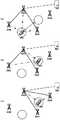
以上情况的典型示例是在用户设备不断移动的场景中,用户设备离开当前协作接入点并接近另一个接入点的情况。图9是根据本公开的实施例在用户设备移动的情况下更新协作接入点的示意图。A typical example of the above situation is a situation where the user equipment leaves the current cooperating access point and approaches another access point in a scenario where the user equipment is constantly moving. FIG. 9 is a schematic diagram of updating a cooperating access point in the case of user equipment movement according to an embodiment of the present disclosure.
在图9的A中,对于UE 100,接入点200A作为数据分发中心,接入点200B和200C作为协作接入点,而接入点200D距离用户设备较远,并没有被选择作为该用户设备的协作接入点。In A of FIG. 9 , for the
如图9的B所示,当UE 100移动到另一个位置时,其与当前协作接入点200B的距离增加而与可用接入点200D的距离减小,此时UE 100可以得到协作接入点200B的当前服务质量和可用接入点200D的预期服务质量。当接入点200B的当前服务质量小于接入点200D的预期服务质量达预定时间段时,UE 100可以决定释放协作接入点200B,并将接入点200D新增作为协作接入点。As shown in B of FIG. 9 , when the
之后,如图9的C所示,UE 100通知数据分发中心200A释放协作接入点200B并新增协作接入点200D,从而建立如图9的C所示的以用户设备为中心的协作传输系统。After that, as shown in C of FIG. 9 , the
根据本公开的实施例的以用户设备为中心的协作传输系统的接入点动态更新机制,可以有效地使得多点协作实时自适应用户设备不断移动的传输场景。According to the dynamic update mechanism of the access point of the cooperative transmission system centered on the user equipment according to the embodiment of the present disclosure, the cooperative multi-point can effectively adapt to the transmission scenario in which the user equipment is constantly moving in real time.
2-1-4.用户设备切换数据分发中心的操作示例2-1-4. Operation example of user equipment switching data distribution center
数据分发中心的切换(switch)指的是由用户设备在协作接入点中选择新的数据分发中心来替换原数据分发中心。可以理解,数据分发中心的替换需要重新建立整个协作架构,因此在目前的数据分发中心的当前服务质量可以满足要求的情况下,即使存在预期服务质量更高的可用接入点,仍然可以不对其进行切换。例如,用户设备可以仅在目前的数据分发中心无法满足服务需求时,才将其释放,然后从其余协作接入点中选择一个成为新的数据分发中心。具体来说,在建立了以用户设备为中心的协作传输系统之后,当UE 100发现数据分发中心的当前服务质量恶化而无法满足服务需求时,用户设备开始替换数据分发中心。The switching of the data distribution center refers to that the user equipment selects a new data distribution center in the cooperative access point to replace the original data distribution center. It can be understood that the replacement of the data distribution center needs to re-establish the entire cooperation architecture. Therefore, if the current service quality of the current data distribution center can meet the requirements, even if there are available access points with higher expected service quality, it is still not necessary to to switch. For example, the user equipment may release the current data distribution center only when it cannot meet the service demand, and then select one of the remaining cooperative access points to become a new data distribution center. Specifically, after establishing the cooperative transmission system centered on the user equipment, when the
数据分发中心的当前服务质量是表示该数据分发中心当前为用户设备提供的服务的质量的指示。可以理解,与预期服务质量类似,当前服务质量也可以基于多个参数来确定,并可以包括表示协作接入点当前提供的服务的质量的多个方面,在此对其不再进行详细说明。The current quality of service of the data distribution center is an indication representing the quality of the service currently provided by the data distribution center to the user equipment. It can be understood that, similar to the expected quality of service, the current quality of service may also be determined based on multiple parameters, and may include multiple aspects representing the quality of service currently provided by the cooperating access point, which will not be described in detail here.
图10是根据本公开的实施例的由用户设备选择切换数据分发中心的处理流程的示意图。该处理流程是由UE 100进行的。FIG. 10 is a schematic diagram of a process flow of selecting and switching a data distribution center by a user equipment according to an embodiment of the present disclosure. This processing flow is performed by the
在步骤1002,UE 100的处理电路110获得当前数据分发中心的当前服务质量并根据接入点的当前服务质量来决定是否切换数据分发中心。具体来说,当前数据分发中心的当前服务质量低于预设阈值持续一定时间之后,UE 100的处理电路110决定切换数据分发中心。例如,当UE 100发现当前数据分发中心与UE 100之间的信道质量(例如,RSRP)低于预设阈值达一定时间之后,决定切换数据分发中心。In step 1002, the processing circuit 110 of the
在步骤1004中,UE 100的处理电路110响应于决定替换数据分发中心,从当前协作接入点中选择一个作为新的数据分发中心。具体来说,在步骤1004中,当UE 100的处理电路110决定切换数据分发中心时,获得各个协作接入点的当前服务质量,并根据当前服务质量来选择数据分发中心。In step 1004, the processing circuit 110 of the
步骤1004中UE 100所进行的操作与参照图5的步骤502以及图6描述的UE 100选择数据分发中心的过程类似,在此不再对其进行详细说明。但是,二者的区别在于UE 100在切换数据分发中心时,仅从当前协作接入点中选择数据分发中心,而不是从所有可用接入点中选择数据分发中心。另外,在切换数据分发中心时,因为协作接入点已经在为用户设备服务,所以此时UE 100根据协作接入点的当前服务质量来选择新的数据分发中心,而非根据接入点的预期服务质量来选择新的数据分发中心。The operation performed by the
在步骤1006中,UE 100的处理电路110通过通信单元120将关于各个协作接入点的信息发送给新的数据分发中心,使得新的数据分发中心在接收到以电子设备为目的地的数据时,将该数据发送给各个协作接入点。In step 1006, the processing circuit 110 of the
在步骤1010中,UE 100的处理电路110释放原数据分发中心。具体来说,UE 100的处理电路110通过通信单元120通知原数据分发中心停止为该用户设备服务并将相关信息上报至服务网关300。In step 1010, the processing circuit 110 of the
以上情况的典型示例是在用户设备不断移动的场景中,用户设备离开当前数据分发中心的情况。图11是根据本公开的实施例在用户设备移动的情况下切换数据分发中心的示意图。A typical example of the above situation is a situation in which the user equipment leaves the current data distribution center in a scenario where the user equipment is constantly moving. FIG. 11 is a schematic diagram of switching a data distribution center in a case where a user equipment moves, according to an embodiment of the present disclosure.
在图11的A中,对于UE 100,接入点200B作为数据分发中心,接入点200A和200C作为协作接入点,而接入点200D距离用户设备较远,并没有被选择作为该用户设备的协作接入点或数据分发中心。In A of FIG. 11 , for the
如图11的B所示,当UE 100移动到另一个位置时,其与当前数据分发中心200B的距离增加,此时UE 100可能发现数据分发中心200B的当前服务质量降低到阈值以下,并因此决定切换数据分发中心。之后,UE 100从协作接入点200A和200C中选择一个作为数据分发中心。As shown in B of FIG. 11 , when the
如图11的C所示,UE 100将协作接入点200A选择作为数据分发中心,将关于协作接入点的信息发送给新的数据分发中心,使得新的数据分发中心建立如图11的C所示的以用户设备为中心的协作传输系统。As shown in C of FIG. 11 , the
另外,在本公开的可选实施例中,UE 100在切换数据分发中心之后,还可以执行增加协作接入点的操作。例如,如图11的D所示,UE 100可以将接入点200D新增作为协作接入点。In addition, in an optional embodiment of the present disclosure, after switching the data distribution center, the
在现有技术中,用户设备会选择信道质量最优的接入点作为其服务接入点,如果发现存在更优的接入点,则会立即进行接入点切换。在这种情况下,用户设备的归属接入点改变即为一次切换。In the prior art, the user equipment will select the access point with the best channel quality as its serving access point, and if a better access point is found, the access point switching will be performed immediately. In this case, the change of the home access point of the user equipment is a handover.
与此相对的,根据本公开的实施例的以用户设备为中心的协作传输系统中,当用户设备的协作接入点进行更新时,对于用户设备的服务质量影响非常小,更新代价也非常低,而只有和服务网关连接的数据分发中心进行切换时,需要重新建立新的数据分发中心和服务网关的连接。在这种情况下,只有数据分发中心切换才被认为是一次切换。In contrast, in the cooperative transmission system centered on the user equipment according to the embodiment of the present disclosure, when the cooperative access point of the user equipment is updated, the service quality of the user equipment is affected very little, and the update cost is also very low. , and only the data distribution center connected to the service gateway is switched, and the connection between the new data distribution center and the service gateway needs to be re-established. In this case, only the data distribution center switchover is considered a switchover.
另外,在根据本公开的实施例的以用户设备为中心的协作传输系统中,由于数据分发中心和多个协作接入点同时为用户服务,因而对数据分发中心的服务质量下降可以有较大容忍度。例如,即使数据分发中心的服务质量开始恶化,因为多个协作接入点仍然可以为用户提供良好的服务质量,所以不需要切换数据分发中心。另外,根据本公开的实施例的协作接入点动态更新机制也可以保证有服务质量较高的协作接入点为用户服务,从而降低数据分发中心的切换频率。另外,在本公开的实施例中,用户设备可以在数据分发中心的服务质量恶化到无法满足服务需求时才开始替换数据分发中心,从而降低数据分发中心的切换频率。In addition, in the cooperative transmission system centered on the user equipment according to the embodiment of the present disclosure, since the data distribution center and a plurality of cooperative access points serve the user at the same time, the service quality of the data distribution center may be greatly degraded. tolerance. For example, even if the quality of service of the data distribution center starts to deteriorate, because multiple cooperative access points can still provide users with good quality of service, there is no need to switch the data distribution center. In addition, the cooperative access point dynamic update mechanism according to the embodiment of the present disclosure can also ensure that a cooperative access point with higher service quality serves the user, thereby reducing the switching frequency of the data distribution center. In addition, in the embodiment of the present disclosure, the user equipment may start to replace the data distribution center when the service quality of the data distribution center deteriorates to such a degree that the service demand cannot be met, thereby reducing the switching frequency of the data distribution center.
因此,根据本公开的实施例的以用户设备为中心的协作传输系统的数据分发中心内部切换机制,可以有效地应对用户设备移动的场景,可以大大减少数据分发中心的切换次数并大大降低数据分发中心切换带来的延时问题。Therefore, the internal switching mechanism of the data distribution center of the cooperative transmission system centered on the user equipment according to the embodiment of the present disclosure can effectively cope with the scenario where the user equipment moves, and can greatly reduce the switching times of the data distribution center and the data distribution center. The problem of delay caused by center switching.
2-2.根据本公开的实施例的接入点的操作示例2-2. Operation example of the access point according to the embodiment of the present disclosure
下文中,从接入点200的角度提供根据本公开的实施例的具体示例。Hereinafter, specific examples of embodiments according to the present disclosure are provided from the perspective of the access point 200 .
2-2-1.接入点在建立以用户设备为中心的协作传输系统的过程中的操作示例2-2-1. Operation example of the access point in the process of establishing a cooperative transmission system centered on the user equipment
图12是根据本公开的实施例的以用户设备为中心的协作传输系统的接入点的处理流程的一个示例。FIG. 12 is an example of a process flow of an access point of a user equipment-centric cooperative transmission system according to an embodiment of the present disclosure.
在步骤1202中,接入点200的处理电路210首先判断接入点200是否被UE 100选择作为协作接入点或数据分发中心。具体来说,接入点200的处理电路210根据通过通信单元220从UE 110接收到的请求,来判断接入点200是否被UE 100选择作为协作接入点或数据分发中心。In step 1202, the processing circuit 210 of the access point 200 first determines whether the access point 200 is selected by the
在接入点200被UE 100选择作为数据分发中心的情况下,在步骤1204中,接入点200的处理电路210将关于UE 100和接入点200作为数据分发中心的信息发送给服务网关300,从而通知服务网关300将以该UE 100为目的地的数据发送给该接入点200。在本公开的实施例中,数据分发中心仅向服务网关300反馈所服务的用户设备的信息以及自身的信息,而不向服务网关300提供为该用户设备服务的协作接入点的信息。因此,对于服务网关300来说,其操作与现有技术的以用户设备为中心的网络类似,即,该服务网关300将以该用户设备为目的地的数据发送给由用户设备选择的一个接入点,而由数据分发中心和协作接入点所进行的操作对服务网关300是透明的、不需要获知的。In the case where the access point 200 is selected by the
之后,在步骤1206中,接入点200的处理电路210从用户设备接收关于协作接入点的信息。根据关于协作接入点的信息,作为数据分发中心的接入点200能够与协作接入点通信以确认向UE 100进行协作传输的资源调度。具体来说,在本公开的实施例中,数据分发中心和协作接入点可以是传统的基站,而在传统蜂窝网络中基站之间以X2接口进行通信及信令交互,实现对用户设备的移动支持、负载管理、小区间干扰协调等功能。因此,通过例如X2接口,数据分发中心和协作接入点之间可以进行关于协作传输的信息交互,确认相互身份,并由数据分发中心统一安排调度该用户设备的资源分配,从而实现多个协作接入点和数据分发中心使用相同的资源块对该用户设备进行协作传输。Thereafter, in step 1206, the processing circuit 210 of the access point 200 receives information about the cooperating access point from the user equipment. Based on the information on the cooperating access points, the access point 200 serving as the data distribution center can communicate with the cooperating access points to confirm resource scheduling for cooperative transmission to the
之后,在步骤1208中,当接入点200从服务网关300接收到以UE 100为目的地的数据时,将该数据发送给协作接入点,使得通过作为数据分发中心的接入点200和协作接入点的协作传输向UE 100发送该数据。After that, in step 1208, when the access point 200 receives the data destined for the
在接入点200被UE 100选择作为协作接入点的情况下,在步骤1210中,该接入点200在从数据分发中心接收到以用户设备为目的地的数据时,在数据分发中心的资源调度下,通过与数据分发中心的协作传输向UE 100发送该数据。In the case where the access point 200 is selected by the
在本公开的一个实施例中,在步骤1202之前,接入点200的处理电路210还可以通过通信单元220向UE 100广播接入点200的识别信号,以供用户设备识别该接入点200。另外,接入点200的处理电路210还可以通过通信单元220向UE 100广播接入点200的固有参数。接入点200的固有参数包括接入点的类型、覆盖范围和工作能力中的一个或多个。In an embodiment of the present disclosure, before step 1202, the processing circuit 210 of the access point 200 may also broadcast the identification signal of the access point 200 to the
在本公开的一个实施例中,在步骤1202之前,接入点200的处理电路210还可以响应于接收到用户设备对于接入点200的状态信息的请求,产生并通过通信单元220发送接入点200的当前状态信息。另外,在本公开的一个实施例中,在步骤1202之前,接入点200的处理电路210还可以响应于接收到用户设备对于接入点200预期分配给该用户设备的资源的请求,产生并通过通信单元220通知用户设备接入点200预期分配给该用户设备的资源。In an embodiment of the present disclosure, before step 1202, the processing circuit 210 of the access point 200 may also generate and send the access point 200 through the communication unit 220 in response to receiving a request from the user equipment for the status information of the access point 200 Current state information for point 200. In addition, in an embodiment of the present disclosure, prior to step 1202, the processing circuit 210 of the access point 200 may further generate and store a request from the user equipment for resources that the access point 200 expects to allocate to the user equipment in response to receiving a request from the user equipment. The user equipment is notified through the communication unit 220 that the access point 200 expects resources allocated to the user equipment.
在本公开的实施例中,接入点作为数据分发中心或协作接入点的身份可以是对于一个用户设备来确定的,也就是说,接入点可以同时成为多个用户设备的协作接入点或数据分发中心,或者,接入点可以对于某些用户设备作为协作接入点而同时对于另外一些用户设备作为数据分发中心。In the embodiment of the present disclosure, the identity of the access point as the data distribution center or the cooperative access point may be determined for one user equipment, that is, the access point may simultaneously become the cooperative access point of multiple user equipments point or data distribution center, alternatively, an access point may act as a cooperating access point for some user equipments while simultaneously acting as a data distribution center for other user equipments.
2-2-2.在更新协作接入点时协作接入点和数据分发中心的操作示例2-2-2. Operation example of cooperative access point and data distribution center when updating cooperative access point
在新增协作接入点的情况下,由该新增的协作接入点所进行的操作与图12中的步骤1210类似,在此省略对其的描述。此外,在新增协作接入点的情况下,由数据分发中心所进行的操作与图12中的步骤1204-1208类似,在此也省略对其的描述。In the case of adding a new cooperative access point, the operation performed by the newly added cooperative access point is similar to step 1210 in FIG. 12 , and the description thereof is omitted here. In addition, in the case of adding a new cooperative access point, the operations performed by the data distribution center are similar to steps 1204-1208 in FIG. 12, and the description thereof is also omitted here.
图13是根据本公开的实施例的在释放协作接入点的情况下,由被释放的协作接入点进行的处理流程的示意图。13 is a schematic diagram of a processing flow performed by the released cooperative access point in the case of releasing the cooperative access point according to an embodiment of the present disclosure.
在步骤1302,接入点200的处理电路210通过通信单元220从UE 100接收到释放请求。在步骤1304,接入点200的处理电路210通过通信单元220向UE 100发送释放确认信息并断开与该UE 100的连接。At step 1302, the processing circuit 210 of the access point 200 receives a release request from the
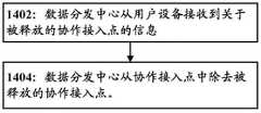
图14是根据本公开的实施例的在释放协作接入点的情况下,由数据分发中心进行的处理流程的示意图。14 is a schematic diagram of a processing flow performed by a data distribution center in the case of releasing a cooperative access point according to an embodiment of the present disclosure.
在步骤1402中,数据分发中心200的处理电路210通过通信单元210从UE 100接收到关于被释放的协作接入点的信息。在步骤1404中,数据分发中心200的处理电路210从协作接入点中除去被释放的协作接入点。In step 1402 , the processing circuit 210 of the data distribution center 200 receives information about the released cooperative access point from the
根据本公开的以上各个实施例中记载的根据本公开的以用户设备为中心的协作传输系统的接入点动态更新机制,可以有效地使得多点协作实时自适应用户设备不断移动的传输场景。According to the access point dynamic update mechanism of the user equipment-centric cooperative transmission system described in the above embodiments of the present disclosure, the coordinated multi-point real-time adaptation can be effectively adapted to the constantly moving transmission scenario of the user equipment.
2-2-3.在切换数据分发中心时数据分发中心的操作示例2-2-3. Operation example of the data distribution center when switching the data distribution center
在切换数据分发中心时,新数据分发中心的操作与参照图12中的步骤1202-1208描述的操作类似,在此省略对其的描述。When switching the data distribution center, the operation of the new data distribution center is similar to that described with reference to steps 1202-1208 in FIG. 12, and the description thereof is omitted here.
图15是根据本公开的实施例的在切换数据分发中心的情况下,由原数据分发中心进行的处理流程的示意图。FIG. 15 is a schematic diagram of the processing flow performed by the original data distribution center in the case of switching the data distribution center according to an embodiment of the present disclosure.
在步骤1502中,原数据分发中心200的处理电路210经由通信单元210从UE 100接收到释放数据分发中心的请求。在步骤1504中,原数据分发中心200的处理电路210经由通信单元210向服务网关300和UE 100发送释放确认信息并断开与该用户设备的连接。In step 1502 , the processing circuit 210 of the original data distribution center 200 receives a request for releasing the data distribution center from the
根据本说明书第2-1-4部分所讨论的原因,根据本公开的以上各个实施例中记载的根据本公开的以用户设备为中心的协作传输系统的数据分发中心内部切换机制,可以有效地应对用户设备移动的场景,可以大大减少数据分发中心的切换次数并大大降低数据分发中心切换带来的延时问题。According to the reasons discussed in section 2-1-4 of this specification, according to the data distribution center switching mechanism of the user equipment-centric cooperative transmission system according to the present disclosure described in the above embodiments of the present disclosure, it can effectively In response to the scenario of user equipment moving, the number of switching of the data distribution center can be greatly reduced and the delay problem caused by the switching of the data distribution center can be greatly reduced.
3.根据本公开的实施例的信令传输过程3. Signaling transmission process according to embodiments of the present disclosure
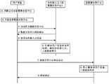
图16是根据本公开的实施例的以用户设备为中心的协作传输系统的信令传输过程的一个示例。具体信令过程如下所示:FIG. 16 is an example of a signaling transmission process of a user equipment-centric cooperative transmission system according to an embodiment of the present disclosure. The specific signaling process is as follows:
(1).接入点广播各自的识别信号和固有参数:接入点广播小区识别信号,使UE可以发现接入点、确定与该接入点的信道质量;并且接入点还广播接入点的固有参数,使得UE能够获得接入点的固有参数,例如接入点的类型、覆盖范围、工作能力等。例如,接入点可以发送同步信号作为识别信号和利用广播信道(BCH)来广播各自的固有参数。(1) The access point broadcasts its own identification signal and inherent parameters: the access point broadcasts the cell identification signal, so that the UE can discover the access point and determine the channel quality with the access point; and the access point also broadcasts the access point The inherent parameters of the point, so that the UE can obtain the inherent parameters of the access point, such as the type of the access point, coverage, working capability, etc. For example, an access point may transmit a synchronization signal as an identification signal and use a broadcast channel (BCH) to broadcast the respective intrinsic parameters.
(2).用户设备通过检测接入点的识别信号来识别周围存在的接入点:用户设备通过接收、检测小区识别信号,来发现其周围可用的接入点。(2) The user equipment identifies the surrounding access points by detecting the identification signal of the access point: the user equipment discovers available access points around it by receiving and detecting the cell identification signal.
(3).用户设备发送连接请求到识别的接入点:用户设备向识别的可用接入点发送连接请求,例如发送随机接入请求,然后接入点开始为该用户设备分配服务资源并与该用户设备建立数据通信连接。例如,用户设备可以通过随机接入过程与接入点进行RRC(radioresource control,无线资源控制)连接,进入RRC连接状态,从而建立与接入点的数据连接。(3) The user equipment sends a connection request to the identified access point: the user equipment sends a connection request to the identified available access point, such as sending a random access request, and then the access point starts to allocate service resources for the user equipment and communicate with the user equipment. The user equipment establishes a data communication connection. For example, the user equipment may perform an RRC (radioresource control, radio resource control) connection with the access point through a random access procedure, and enter an RRC connection state, thereby establishing a data connection with the access point.
(4).接入点生成该接入点的当前状态信息和确定预期为该用户设备分配的资源。(4) The access point generates current state information of the access point and determines the resources expected to be allocated for the user equipment.
(5).接入点发送接入点的当前状态信息给该用户设备和通知用户设备预期为该用户设备分配的资源。例如,接入点除了上述的广播信道,还可以例如以无线电资源控制信令作为载体并通过物理下行共享信道(PDSCH,physical downlink share channel),或者可以利用下行控制信息(DCI)作为载体并通过物理下行控制信道(PDCCH)将接入点的当前状态信息和关于预期为该用户设备分配的资源的信息发送给用户设备。(5) The access point sends the current state information of the access point to the user equipment and informs the user equipment of resources expected to be allocated for the user equipment. For example, in addition to the above-mentioned broadcast channel, the access point can also use radio resource control signaling as a bearer and pass a physical downlink shared channel (PDSCH, physical downlink share channel), or can use downlink control information (DCI) as a bearer and pass through The Physical Downlink Control Channel (PDCCH) transmits the current state information of the access point and information about the resources expected to be allocated for the user equipment to the user equipment.
(6).用户设备判断是否将该接入点作为协作接入点。(6). The user equipment determines whether to use the access point as a cooperative access point.
(7).用户设备发送协作接入点请求到接入点。例如,用户设备决定该接入点为协作接入点后,可以通过物理上行控制信道(PUCCH,physical uplink control channel)来将协作接入点请求发送到该接入点。(7). The user equipment sends a cooperative access point request to the access point. For example, after the user equipment determines that the access point is a coordinated access point, it may send a coordinated access point request to the access point through a physical uplink control channel (PUCCH, physical uplink control channel).
(8).接入点确认作为该用户设备的协作接入点的请求:接入点将确认信息反馈到申请用户设备,成为其协作接入点。例如,接入点可以通过物理下行控制信道(PDCCH)将确认信息反馈到申请用户设备。(8) The access point confirms the request to be the cooperative access point of the user equipment: the access point feeds back the confirmation information to the applying user equipment to become its cooperative access point. For example, the access point may feed back the confirmation information to the applying user equipment through the Physical Downlink Control Channel (PDCCH).
(9).用户设备判决是否将该接入点作为数据分发中心。(9) The user equipment decides whether to use the access point as a data distribution center.
(10).用户设备发送数据分发中心请求到该接入点。例如,用户设备判决该接入点为数据分发中心后,可以通过物理上行控制信道(PUCCH)将数据分发中心请求发送到该接入点。(10). The user equipment sends a data distribution center request to the access point. For example, after determining that the access point is the data distribution center, the user equipment may send the data distribution center request to the access point through a physical uplink control channel (PUCCH).
(11).接入点确认作为该用户设备的数据分发中心的请求。例如,接入点可以通过物理下行控制信道(PDCCH)将确认信息反馈到申请用户设备,成为其数据分发中心。(11). The access point confirms the request as the data distribution center of the user equipment. For example, the access point can feed back the confirmation information to the applying user equipment through the physical downlink control channel (PDCCH) to become its data distribution center.
(12).用户设备将为其服务的协作接入点信息发送到数据分发中心。例如,用户设备确认数据分发中心后,可以通过物理上行控制信道(PUCCH)向数据分发中心报告为其服务的协作接入点的信息。(12) The user equipment sends the information of the cooperative access point serving the user equipment to the data distribution center. For example, after confirming the data distribution center, the user equipment may report the information of the cooperative access point serving the data distribution center to the data distribution center through a physical uplink control channel (PUCCH).
(13).数据分发中心生成为以该用户设备为中心的协作传输系统:数据分发中心获取该用户设备的其余协作接入点信息后,在本地生成以该用户设备为中心的协作传输结构。(13) The data distribution center generates a cooperative transmission system centered on the user equipment: after the data distribution center obtains the information of the remaining cooperative access points of the user equipment, it locally generates a cooperative transmission structure centered on the user equipment.
(14).数据分发中心通知该用户设备的其余协作接入点相关协作信息。例如,数据分发中心可以通过例如X2接口通知该用户设备的协作接入点,确认协作传输的资源调度。(14) The data distribution center notifies the other cooperative access points of the user equipment of relevant cooperation information. For example, the data distribution center may notify the cooperative access point of the user equipment through, for example, the X2 interface, to confirm the resource scheduling of the cooperative transmission.
(15).协作点发送确认信息到数据分发中心。例如,该用户设备的协作接入点可以通过例如X2接口将确认信息反馈到该用户设备的数据分发中心。(15). The cooperation point sends confirmation information to the data distribution center. For example, the cooperative access point of the user equipment may feed back the confirmation information to the data distribution center of the user equipment through, for example, the X2 interface.
(16).数据分发中心向服务网关报告用户设备和数据分发中心信息。例如,数据分发中心完成以该用户设备为中心的协作传输系统后,可以将用户设备和数据分发中心的信息通过例如S1-U接口报告给服务网关。(16). The data distribution center reports the user equipment and data distribution center information to the service gateway. For example, after the data distribution center completes the cooperative transmission system centered on the user equipment, it can report the information of the user equipment and the data distribution center to the serving gateway through, for example, the S1-U interface.
(17).网关发送确认信息到数据分发中心。例如,服务网关收到数据分发中心的报告后,确认用户设备与数据分发中心的结构,并可以通过例如S1-U接口反馈确认信息。(17). The gateway sends confirmation information to the data distribution center. For example, after receiving the report from the data distribution center, the service gateway confirms the structure of the user equipment and the data distribution center, and can feed back confirmation information through, for example, the S1-U interface.
到此为止,已经建立了根据本公开的实施例的以用户设备为中心的协作传输系统。之后,在服务网关向用户设备发送数据时,该数据被发送给数据分发中心,在由数据分发中心发送给各个协作接入点,从而通过数据分发中心和协作接入点的协作传输来向用户设备发送数据。So far, a user equipment-centric cooperative transmission system according to an embodiment of the present disclosure has been established. After that, when the serving gateway sends data to the user equipment, the data is sent to the data distribution center, and then sent to each cooperative access point by the data distribution center, so that the data is sent to the user through the cooperative transmission between the data distribution center and the cooperative access point. The device sends data.
图17是根据本公开的实施例的更新协作接入点的信令传输过程的一个示例。17 is an example of a signaling transmission process for updating a cooperating access point according to an embodiment of the present disclosure.
用户设备新增协作接入点的具体信令过程如下所示:The specific signaling process for the user equipment to add a collaborative access point is as follows:
(1)-(8).用户设备识别新的接入点,并加入到现有协作接入点集合中,这部分过程与如图16所示的建立以用户设备为中心的协作传输系统的信令传输过程的(1)-(8)是类似的,在此不再赘述。(1)-(8). The user equipment identifies the new access point and adds it to the existing cooperative access point set. This part of the process is similar to the process of establishing a user equipment-centric cooperative transmission system as shown in FIG. 16 . (1)-(8) of the signaling transmission process are similar and will not be repeated here.
(9).报告更新协作接入点信息:当用户设备新增协作接入点后,将新增的协作接入点信息上报给数据分发中心。例如,用户设备可以通过物理上行控制信道(PUCCH)向数据分发中心报告新增的协作接入点的信息。(9) Report and update cooperative access point information: After the user equipment adds a new cooperative access point, it reports the newly added cooperative access point information to the data distribution center. For example, the user equipment may report the information of the newly added cooperative access point to the data distribution center through a physical uplink control channel (PUCCH).
(10).更新该用户设备的协作结构:数据分发中心根据用户设备上报协作接入点信息后,将对以用户设备为中心的协作传输结构进行更新。(10) Update the cooperative structure of the user equipment: After the data distribution center reports the cooperative access point information according to the user equipment, it will update the cooperative transmission structure centered on the user equipment.
(11).通知新加入的协作接入点:数据分发中心将通知该用户设备更新的协作接入点,确认协作传输的资源调度。例如,数据分发中心可以通过例如X2接口通知该用户设备的协作接入点,确认协作传输的资源调度。(11) Notify the newly added cooperative access point: the data distribution center will notify the updated cooperative access point of the user equipment to confirm the resource scheduling of the cooperative transmission. For example, the data distribution center may notify the cooperative access point of the user equipment through, for example, the X2 interface, to confirm the resource scheduling of the cooperative transmission.
(12).协作接入点确认数据分发中心:该协作接入点将反馈确认信息到该用户设备的数据分发中心。例如,该协作接入点可以通过例如X2接口将确认信息反馈到数据分发中心。(12) The cooperative access point confirms the data distribution center: the cooperative access point feeds back the confirmation information to the data distribution center of the user equipment. For example, the cooperative access point can feed back the confirmation information to the data distribution center through, for example, the X2 interface.
仍然参照图17,用户设备释放协作接入点的具体信令过程如下所示:Still referring to FIG. 17 , the specific signaling process for the user equipment to release the cooperative access point is as follows:
(13).判决是否释放协作接入点:对于已经为用户设备服务的协作接入点,用户设备将通过其服务质量来判决是否释放该协作接入点。(13) Judging whether to release the cooperative access point: For the cooperative access point that has served the user equipment, the user equipment will decide whether to release the cooperative access point according to its service quality.
(14).发送释放协作接入点请求:用户设备判断释放协作接入点后,将发送释放请求给协作接入点。例如,用户设备判断释放该协作接入点后,可以通过物理上行控制信道(PUCCH)来将释放请求发送到该接入点。(14) Sending a request for releasing the cooperative access point: after the user equipment determines to release the cooperative access point, it sends a release request to the cooperative access point. For example, after judging to release the coordinated access point, the user equipment may send a release request to the access point through a physical uplink control channel (PUCCH).
(15).释放确认:协作接入点收到用户设备的释放请求后,将终止为该用户设备服务,并反馈释放确认信息。例如,协作接入点可以通过物理下行控制信道(PDCCH)将释放确认信息反馈到用户设备。(15) Release confirmation: After receiving the release request from the user equipment, the cooperative access point will terminate the service for the user equipment and feed back release confirmation information. For example, the cooperating access point may feed back the release confirmation information to the user equipment through the Physical Downlink Control Channel (PDCCH).
(9).报告更新协作接入点信息:当用户设备释放现有协作接入点后,将被释放的协作接入点信息上报给数据分发中心。例如,用户设备可以通过物理上行控制信道(PUCCH)向数据分发中心报告被释放的协作接入点的信息。(9) Report and update the information of the cooperative access point: after the user equipment releases the existing cooperative access point, it reports the information of the released cooperative access point to the data distribution center. For example, the user equipment may report the information of the released cooperative access points to the data distribution center through a physical uplink control channel (PUCCH).
(10).更新该用户设备的协作结构:数据分发中心根据用户设备上报协作接入点信息后,将对该用户设备的协作结构进行更新。(10) Update the cooperation structure of the user equipment: After the data distribution center reports the cooperation access point information according to the user equipment, it will update the cooperation structure of the user equipment.
通过图17中示出的信令过程,能够动态地更新协作接入点。Through the signaling process shown in FIG. 17, the cooperating access points can be dynamically updated.
图18是根据本公开的实施例的切换数据分发中心的信令传输过程的一个示例。具体信令过程如下所示:FIG. 18 is an example of a signaling transmission process for switching a data distribution center according to an embodiment of the present disclosure. The specific signaling process is as follows:
(1).判决是否切换数据分发中心:用户设备通过监测数据分发中心的服务质量来判决是否切换数据分发中心。(1) Judging whether to switch the data distribution center: The user equipment determines whether to switch the data distribution center by monitoring the service quality of the data distribution center.
(2).重新选择数据分发中心:用户设备根据协作接入点的当前服务质量,从协作接入点中选择新的数据分发中心。(2) Re-selecting the data distribution center: the user equipment selects a new data distribution center from the cooperative access points according to the current quality of service of the cooperative access points.
(3)-(6).用户设备请求该协作接入点作为新的数据分发中心并将其他协作接入点的信息发送给新的数据分发中心,新的数据分发中心生成以该用户设备为中心的协作传输结构,通知协作接入点并上报服务网关。这部分过程与如图16所示的信令传输过程的(10)-(17)是类似的,在此不再赘述。(3)-(6). The user equipment requests the cooperative access point as the new data distribution center and sends the information of other cooperative access points to the new data distribution center, and the new data distribution center generates the user equipment as the new data distribution center. The cooperative transmission structure of the center notifies the cooperative access point and reports to the service gateway. This part of the process is similar to (10)-(17) of the signaling transmission process shown in FIG. 16, and will not be repeated here.
(7).数据分发中心释放请求:用户设备将发送释放请求到原数据分发中心。例如,用户设备可以通过物理上行控制信道(PUCCH)向原数据分发中心发送释放请求。(7) Data distribution center release request: the user equipment will send a release request to the original data distribution center. For example, the user equipment may send a release request to the original data distribution center through a physical uplink control channel (PUCCH).
(8).原数据分发中心停止服务:原数据分发中心将停止为该用户设备服务,并将相关信息上报至服务网关。(8) The original data distribution center stops serving: the original data distribution center will stop serving the user equipment and report the relevant information to the service gateway.
(9).释放确认:原数据分发中心发送释放确认信息给该用户设备。例如,原数据分发中心可以通过物理下行控制信道(PDCCH)将释放确认反馈到用户设备。(9) Release confirmation: the original data distribution center sends release confirmation information to the user equipment. For example, the original data distribution center may feed back the release confirmation to the user equipment through the physical downlink control channel (PDCCH).
通过图18中示出的信令过程,能够动态地切换数据分发中心。Through the signaling process shown in FIG. 18, the data distribution center can be switched dynamically.
4.根据本公开的实施例的以用户设备为中心的协作传输系统的仿真4. Simulation of a User Equipment-Centric Cooperative Transmission System According to Embodiments of the Present Disclosure
图19比较了根据本公开的实施例的以用户设备为中心的协作传输系统和传统CoMP技术的传输延迟。这里我们都假设有3个接入点进行协作传输,其中传统CoMP由三个eNB来提供协作传输,根据本公开的实施例的以用户设备为中心的协作传输系统由一个数据分发中心和两个协作接入点来提供协作传输。在1000m*1000m的正方区域中,假设总共有10个随机分布的用户设备,通过仿真计算了对从服务网关到10个用户进行多次数据传输的延迟,获得了传输延迟的概率分布函数图,然后通过比较概率分布函数来比较根据本公开的实施例的以用户设备为中心的协作传输系统和传统CoMP技术的传输延迟。FIG. 19 compares the transmission delay of a user equipment-centric cooperative transmission system and a conventional CoMP technology according to an embodiment of the present disclosure. Here we all assume that there are three access points for cooperative transmission, in which the traditional CoMP is provided by three eNBs to provide cooperative transmission, and the cooperative transmission system centered on the user equipment according to the embodiment of the present disclosure consists of a data distribution center and two Cooperative access points to provide cooperative transport. In a square area of 1000m*1000m, assuming a total of 10 randomly distributed user equipments, the delay of multiple data transmissions from the service gateway to 10 users is calculated by simulation, and the probability distribution function diagram of the transmission delay is obtained, Then, the transmission delays of the UE-centric cooperative transmission system according to the embodiment of the present disclosure and the conventional CoMP technology are compared by comparing the probability distribution functions.
假设每个用户设备都需要接收一个20Mb大小的数据包。假设服务网关拥有20MHz的传输带宽,传输速率为5bps/Hz,用于发送数据给接入点。因此,在从服务网关将20Mb的数据传输给一个接入点时,数据传输延迟为:20Mb/(5bps/Hz*20MHz),其中20Mb是数据包大小,5bps/Hz是服务网关到接入点速率,20MHz是服务网关传输带宽。之后,从接入点到用户设备的传输延迟为20Mb/(r bps/Hz*5MHz),其中r bps/Hz表示接入点到用户设备的传输速率,5MHz表示传输带宽。It is assumed that each user equipment needs to receive a data packet of 20Mb size. Assume that the serving gateway has a transmission bandwidth of 20MHz and a transmission rate of 5bps/Hz for sending data to the access point. Therefore, when transferring 20Mb of data from the serving gateway to an access point, the data transfer delay is: 20Mb/(5bps/Hz*20MHz), where 20Mb is the packet size and 5bps/Hz is the serving gateway to the access point rate, 20MHz is the transmission bandwidth of the service gateway. After that, the transmission delay from the access point to the user equipment is 20Mb/(r bps/Hz*5MHz), where r bps/Hz represents the transmission rate from the access point to the user equipment, and 5MHz represents the transmission bandwidth.
在传统CoMP技术中,需要从服务网关将20Mb的数据包传输给三个接入点,因此,从服务网关到三个接入点的数据传输延迟大约为从服务网关到一个接入点的数据传输延迟的三倍,即,3*20Mb/(5bps/Hz*20MHz)。In the traditional CoMP technology, 20Mb data packets need to be transmitted from the serving gateway to three access points, so the data transmission delay from the serving gateway to three access points is about the same as that from the serving gateway to one access point. Three times the propagation delay, ie, 3*20Mb/(5bps/Hz*20MHz).
在本公开的实施例的以用户设备为中心的协作传输系统中,服务网关仅需要将20Mb的数据包传输给服务网关,而不需要将该数据包传输给其他的协作接入点,所以从服务网关到数据分发中心的数据传输延迟仅为:20Mb/(5bps/Hz*20MHz)。In the cooperative transmission system centered on the user equipment according to the embodiment of the present disclosure, the serving gateway only needs to transmit the 20Mb data packet to the serving gateway, and does not need to transmit the data packet to other cooperative access points, so from The data transmission delay from the service gateway to the data distribution center is only: 20Mb/(5bps/Hz*20MHz).
另外,在本公开的实施例的以用户设备为中心的协作传输系统中,由于数据分发中心和协作接入点之间距离很近,可以通过速度较快的有线通信或短距离毫米波频段进行通信,因此从数据分发中心到协作接入点的数据传输延迟相比于以上数据传输延迟来说要小得多,在计算从服务网关到用户设备的传输延迟时基本可以被忽略。对于现有毫米波频段来说,常用的频段例如为Ka频段(26.5GHz~40GHz),可用带宽巨大(GHz级别的带宽),因此,相比于服务网关到接入点和接入点到用户设备所用的传统频点1~3GHz频段中MHz级别的带宽(在以上仿真中为5MHz)来说,毫无疑问是巨大的,因此数据传输速率可能有近千倍的差距。另外,由毫米波传输技术中的定向传输技术,可以实现数据分发中心对不同方向协作接入点的同频同时传输,即并行传输从而进一步提高从数据分发中心到协作接入点的数据传输速率。In addition, in the cooperative transmission system centered on the user equipment according to the embodiment of the present disclosure, since the distance between the data distribution center and the cooperative access point is very close, the data distribution center and the cooperative access point can be connected through fast wired communication or short-distance millimeter wave frequency band. Therefore, the data transmission delay from the data distribution center to the cooperative access point is much smaller than the above data transmission delay, and can be basically ignored when calculating the transmission delay from the serving gateway to the user equipment. For the existing millimeter-wave frequency band, the commonly used frequency band is, for example, the Ka frequency band (26.5GHz-40GHz), and the available bandwidth is huge (GHz-level bandwidth). Therefore, compared with the service gateway to the access point and the access point to the user The bandwidth of MHz level in the traditional 1-3GHz frequency band used by the device (5MHz in the above simulation) is undoubtedly huge, so the data transmission rate may have a difference of nearly a thousand times. In addition, the directional transmission technology in the millimeter wave transmission technology can realize the same-frequency simultaneous transmission of the data distribution center to the cooperative access points in different directions, that is, parallel transmission, thereby further improving the data transmission rate from the data distribution center to the cooperative access points. .
因此,总的来说,在传统CoMP技术中,从服务网关到用户设备的传输延迟约为3*20Mb/(5bps/Hz*20MHz)+20Mb/(r bps/Hz*5MHz),而在本公开的实施例的以用户设备为中心的协作传输系统中,从服务网关到用户设备的传输延迟约为20Mb/(5bps/Hz*20MHz)+20Mb/(r bps/Hz*5MHz)。很明显,本公开的实施例的以用户设备为中心的协作传输系统能够显著地减少从服务网关到用户设备的传输延迟。Therefore, in general, in the traditional CoMP technology, the transmission delay from the serving gateway to the user equipment is about 3*20Mb/(5bps/Hz*20MHz)+20Mb/(r bps/Hz*5MHz), while in this In the user equipment-centric cooperative transmission system of the disclosed embodiment, the transmission delay from the serving gateway to the user equipment is about 20Mb/(5bps/Hz*20MHz)+20Mb/(r bps/Hz*5MHz). Obviously, the cooperative transmission system centered on the user equipment according to the embodiment of the present disclosure can significantly reduce the transmission delay from the serving gateway to the user equipment.
从图19的仿真结果也可以看出,根据本公开的实施例的技术方案可以大大减少从服务网关到用户设备的传输延迟。It can also be seen from the simulation result in FIG. 19 that the technical solution according to the embodiment of the present disclosure can greatly reduce the transmission delay from the serving gateway to the user equipment.
可以看到根据本公开的实施例通过利用接入点之间的短距离毫米波传输来实现多点协作数据传输,大大节省了服务网关到接入点的传输资源。It can be seen that according to the embodiments of the present disclosure, coordinated multi-point data transmission is realized by utilizing short-distance millimeter wave transmission between access points, which greatly saves the transmission resources from the serving gateway to the access points.
图20比较了用户设备移动穿过随机分布了N个接入点的区域的场景下,根据本公开的实施例的以用户设备为中心的协作传输系统和现有技术的接入点切换的次数。FIG. 20 compares the number of times of handover of access points between a user equipment-centric cooperative transmission system according to an embodiment of the present disclosure and the prior art in a scenario where the user equipment moves through an area where N access points are randomly distributed .
在现有技术中,用户设备会选择信道质量最优的接入点作为其服务接入点,如果发现存在更优的接入点,则会立即进行接入点切换。在这种情况下,用户设备的归属接入点改变即为一次切换。In the prior art, the user equipment will select the access point with the best channel quality as its serving access point, and if a better access point is found, the access point switching will be performed immediately. In this case, the change of the home access point of the user equipment is a handover.
与此相对的,根据本公开的实施例的以用户设备为中心的协作传输系统中,当用户设备的协作接入点进行更新时,对于用户设备的服务质量影响非常小,更新代价也非常低,而只有和服务网关连接的数据分发中心进行切换时,需要重新建立新的数据分发中心和服务网关的连接。在这种情况下,只有数据分发中心切换才被认为是一次切换。In contrast, in the cooperative transmission system centered on the user equipment according to the embodiment of the present disclosure, when the cooperative access point of the user equipment is updated, the service quality of the user equipment is affected very little, and the update cost is also very low. , and only the data distribution center connected to the service gateway is switched, and the connection between the new data distribution center and the service gateway needs to be re-established. In this case, only the data distribution center switchover is considered a switchover.
根据本公开的实施例,在根据本公开的实施例的以用户设备为中心的协作传输系统中,数据分发中心的切换次数被减小。因此,在协作接入点的个数为M的情况下,因为数据分发中心保持为用户设备服务的时间会相应延长,可以有效地降低数据分发中心的切换次数。According to the embodiment of the present disclosure, in the cooperative transmission system centered on the user equipment according to the embodiment of the present disclosure, the number of switching times of the data distribution center is reduced. Therefore, in the case where the number of cooperative access points is M, because the time that the data distribution center keeps serving the user equipment will be extended accordingly, the switching times of the data distribution center can be effectively reduced.
如图20所示,可以发现,在N=40,M=3的设定下,根据本公开的实施例的以用户设备为中心的协作传输系统中,数据分发中心的切换次数只有传统方案切换次数的一半。同时,随着协作接入点个数M的增加,切换次数还可以进一步降低。As shown in FIG. 20 , it can be found that under the setting of N=40 and M=3, in the cooperative transmission system centered on the user equipment according to the embodiment of the present disclosure, the number of switching times of the data distribution center is only the switching of the traditional scheme half the number of times. At the same time, as the number M of cooperative access points increases, the number of handovers can be further reduced.
5.应用示例5. Application example
本公开内容的技术能够应用于各种产品。The techniques of this disclosure can be applied to various products.
例如,用户设备100可以被实现为移动终端(诸如智能电话、平板个人计算机(PC)、笔记本式PC、便携式游戏终端、便携式/加密狗型移动路由器和数字摄像装置)或者车载终端(诸如汽车导航设备)。用户设备100还可以被实现为执行机器对机器(M2M)通信的终端(也称为机器类型通信(MTC)终端)。此外,用户设备100可以为安装在上述终端中的每个终端上的无线通信模块(诸如包括单个晶片的集成电路模块)。For example, the
例如,接入点200可以被实现为任何类型的演进型节点B(eNB),诸如宏eNB和小eNB。小eNB可以为覆盖比宏小区小的小区的eNB,诸如微微eNB、微eNB和家庭(毫微微)eNB。代替地,接入点200可以被实现为任何其他类型的基站,诸如NodeB和基站收发台(BTS)。接入点200可以包括:被配置为控制无线通信的主体(也称为基站设备)以及设置在与主体不同的地方的一个或多个远程无线头端(RRH)。另外,下面将描述的各种类型的终端均可以通过暂时地或半持久性地执行接入点功能而作为接入点200工作。For example, access point 200 may be implemented as any type of evolved Node B (eNB), such as macro eNBs and small eNBs. Small eNBs may be eNBs covering cells smaller than macro cells, such as pico eNBs, micro eNBs, and home (femto) eNBs. Alternatively, the access point 200 may be implemented as any other type of base station, such as a NodeB and a base transceiver station (BTS). The access point 200 may include a subject (also referred to as a base station device) configured to control wireless communications, and one or more remote radio heads (RRHs) disposed at a different location than the subject. In addition, various types of terminals to be described below can operate as the access point 200 by temporarily or semi-persistently performing the access point function.
例如,服务网关300可以被实现为任何类型的服务器,诸如塔式服务器、机架式服务器以及刀片式服务器。服务网关300可以为安装在服务器上的控制模块(诸如包括单个晶片的集成电路模块,以及插入到刀片式服务器的槽中的卡或刀片(blade))。For example,
5-1.关于用户设备的应用示例5-1. Application example about user equipment
(第一应用示例)(First application example)
图21是示出可以应用本公开内容的技术的智能电话900的示意性配置的示例的框图。智能电话900包括处理器901、存储器902、存储装置903、外部连接接口904、摄像装置906、传感器907、麦克风908、输入装置909、显示装置910、扬声器911、无线通信接口912、一个或多个天线开关915、一个或多个天线916、总线917、电池918以及辅助控制器919。FIG. 21 is a block diagram showing an example of a schematic configuration of a
处理器901可以为例如CPU或片上系统(SoC),并且控制智能电话900的应用层和另外层的功能。存储器902包括RAM和ROM,并且存储数据和由处理器901执行的程序。存储装置903可以包括存储介质,诸如半导体存储器和硬盘。外部连接接口904为用于将外部装置(诸如存储卡和通用串行总线(USB)装置)连接至智能电话900的接口。The
摄像装置906包括图像传感器(诸如电荷耦合器件(CCD)和互补金属氧化物半导体(CMOS)),并且生成捕获图像。传感器907可以包括一组传感器,诸如测量传感器、陀螺仪传感器、地磁传感器和加速度传感器。麦克风908将输入到智能电话900的声音转换为音频信号。输入装置909包括例如被配置为检测显示装置910的屏幕上的触摸的触摸传感器、小键盘、键盘、按钮或开关,并且接收从用户输入的操作或信息。显示装置910包括屏幕(诸如液晶显示器(LCD)和有机发光二极管(OLED)显示器),并且显示智能电话900的输出图像。扬声器911将从智能电话900输出的音频信号转换为声音。The
无线通信接口912支持任何蜂窝通信方案(诸如LTE和LTE-先进),并且执行无线通信。无线通信接口912通常可以包括例如BB处理器913和RF电路914。BB处理器913可以执行例如编码/解码、调制/解调以及复用/解复用,并且执行用于无线通信的各种类型的信号处理。同时,RF电路914可以包括例如混频器、滤波器和放大器,并且经由天线916来传送和接收无线信号。无线通信接口912可以为其上集成有BB处理器913和RF电路914的一个芯片模块。如图21所示,无线通信接口912可以包括多个BB处理器913和多个RF电路914。虽然图21示出其中无线通信接口912包括多个BB处理器913和多个RF电路914的示例,但是无线通信接口912也可以包括单个BB处理器913或单个RF电路914。The
此外,除了蜂窝通信方案之外,无线通信接口912可以支持另外类型的无线通信方案,诸如短距离无线通信方案、近场通信方案和无线局域网(LAN)方案。在此情况下,无线通信接口912可以包括针对每种无线通信方案的BB处理器913和RF电路914。Furthermore, in addition to cellular communication schemes, the
天线开关915中的每一个在包括在无线通信接口912中的多个电路(例如用于不同的无线通信方案的电路)之间切换天线916的连接目的地。Each of the
天线916中的每一个均包括单个或多个天线元件(诸如包括在MIMO天线中的多个天线元件),并且用于无线通信接口912传送和接收无线信号。如图21所示,智能电话900可以包括多个天线916。虽然图21示出其中智能电话900包括多个天线916的示例,但是智能电话900也可以包括单个天线916。Each of the
此外,智能电话900可以包括针对每种无线通信方案的天线916。在此情况下,天线开关915可以从智能电话900的配置中省略。Additionally, the
总线917将处理器901、存储器902、存储装置903、外部连接接口904、摄像装置906、传感器907、麦克风908、输入装置909、显示装置910、扬声器911、无线通信接口912以及辅助控制器919彼此连接。电池918经由馈线向图21所示的智能电话900的各个块提供电力,馈线在图中被部分地示为虚线。辅助控制器919例如在睡眠模式下操作智能电话900的最小必需功能。The
在图21中示出的智能电话900中,参考图2描述的处理电路110中包括的一个或多个组件(选择单元111、发送单元112和/或接收单元113)可被实现在无线通信接口912中。可替代地,这些组件中的至少一部分可被实现在处理器901或者辅助控制器919中。作为一个示例,智能电话900包含无线通信接口912的一部分(例如,BB处理器913)或者整体,和/或包括处理器901和/或辅助控制器919的模块,并且一个或多个组件可被实现在该模块中。在这种情况下,该模块可以存储允许处理起一个或多个组件的作用的程序(换言之,用于允许处理器执行一个或多个组件的操作的程序),并且可以执行该程序。作为另一个示例,用于允许处理器起一个或多个组件的作用的程序可被安装在智能电话900中,并且无线通信接口912(例如,BB处理器913)、处理器901和/或辅助控制器919可以执行该程序。如上所述,作为包括一个或多个组件的装置,智能电话900或者模块可被提供,并且用于允许处理器起一个或多个组件的作用的程序可被提供。另外,将程序记录在其中的可读介质可被提供。In the
另外,在图21中示出的智能电话900中,例如,参考图2描述的通信单元120可被实现在无线通信接口912(例如,RF电路914)中。In addition, in the
(第二应用示例)(Second application example)
图22是示出可以应用本公开内容的技术的汽车导航设备920的示意性配置的示例的框图。汽车导航设备920包括处理器921、存储器922、全球定位系统(GPS)模块924、传感器925、数据接口926、内容播放器927、存储介质接口928、输入装置929、显示装置930、扬声器931、无线通信接口933、一个或多个天线开关936、一个或多个天线937以及电池938。FIG. 22 is a block diagram showing an example of a schematic configuration of a
处理器921可以为例如CPU或SoC,并且控制汽车导航设备920的导航功能和另外的功能。存储器922包括RAM和ROM,并且存储数据和由处理器921执行的程序。The
GPS模块924使用从GPS卫星接收的GPS信号来测量汽车导航设备920的位置(诸如纬度、经度和高度)。传感器925可以包括一组传感器,诸如陀螺仪传感器、地磁传感器和空气压力传感器。数据接口926经由未示出的终端而连接到例如车载网络941,并且获取由车辆生成的数据(诸如车速数据)。The
内容播放器927再现存储在存储介质(诸如CD和DVD)中的内容,该存储介质被插入到存储介质接口928中。输入装置929包括例如被配置为检测显示装置930的屏幕上的触摸的触摸传感器、按钮或开关,并且接收从用户输入的操作或信息。显示装置930包括诸如LCD或OLED显示器的屏幕,并且显示导航功能的图像或再现的内容。扬声器931输出导航功能的声音或再现的内容。The
无线通信接口933支持任何蜂窝通信方案(诸如LTE和LTE-先进),并且执行无线通信。无线通信接口933通常可以包括例如BB处理器934和RF电路935。BB处理器934可以执行例如编码/解码、调制/解调以及复用/解复用,并且执行用于无线通信的各种类型的信号处理。同时,RF电路935可以包括例如混频器、滤波器和放大器,并且经由天线937来传送和接收无线信号。无线通信接口933还可以为其上集成有BB处理器934和RF电路935的一个芯片模块。如图22所示,无线通信接口933可以包括多个BB处理器934和多个RF电路935。虽然图22示出其中无线通信接口933包括多个BB处理器934和多个RF电路935的示例,但是无线通信接口933也可以包括单个BB处理器934或单个RF电路935。The
此外,除了蜂窝通信方案之外,无线通信接口933可以支持另外类型的无线通信方案,诸如短距离无线通信方案、近场通信方案和无线LAN方案。在此情况下,针对每种无线通信方案,无线通信接口933可以包括BB处理器934和RF电路935。Also, in addition to the cellular communication scheme, the
天线开关936中的每一个在包括在无线通信接口933中的多个电路(诸如用于不同的无线通信方案的电路)之间切换天线937的连接目的地。Each of the
天线937中的每一个均包括单个或多个天线元件(诸如包括在MIMO天线中的多个天线元件),并且用于无线通信接口933传送和接收无线信号。如图22所示,汽车导航设备920可以包括多个天线937。虽然图22示出其中汽车导航设备920包括多个天线937的示例,但是汽车导航设备920也可以包括单个天线937。Each of the
此外,汽车导航设备920可以包括针对每种无线通信方案的天线937。在此情况下,天线开关936可以从汽车导航设备920的配置中省略。In addition, the
电池938经由馈线向图22所示的汽车导航设备920的各个块提供电力,馈线在图中被部分地示为虚线。电池938累积从车辆提供的电力。The
在图22中示出的汽车导航装置920中,参考图2描述的处理电路110中包括的一个或多个组件(选择单元111、发送单元112和/或接收单元113)可被实现在无线通信接口933中。可替代地,这些组件中的至少一部分可被实现在处理器921中。作为一个示例,汽车导航装置920包含无线通信接口933的一部分(例如,BB处理器934)或者整体,和/或包括处理器921的模块,并且一个或多个组件可被实现在该模块中。在这种情况下,该模块可以存储允许处理起一个或多个组件的作用的程序(换言之,用于允许处理器执行一个或多个组件的操作的程序),并且可以执行该程序。作为另一个示例,用于允许处理器起一个或多个组件的作用的程序可被安装在汽车导航装置920中,并且无线通信接口933(例如,BB处理器934)和/或处理器921可以执行该程序。如上所述,作为包括一个或多个组件的装置,汽车导航装置920或者模块可被提供,并且用于允许处理器起一个或多个组件的作用的程序可被提供。另外,将程序记录在其中的可读介质可被提供。In the
另外,在图22中示出的汽车导航装置920中,例如,参考图2描述的通信单元120可被实现在无线通信接口933(例如,RF电路935)中。In addition, in the
本公开内容的技术也可以被实现为包括汽车导航设备920、车载网络941以及车辆模块942中的一个或多个块的车载系统(或车辆)940。车辆模块942生成车辆数据(诸如车速、发动机速度和故障信息),并且将所生成的数据输出至车载网络941。The techniques of this disclosure may also be implemented as an in-vehicle system (or vehicle) 940 that includes one or more blocks of a
5-2.关于接入点的应用示例5-2. Application example about access point
(第一应用示例)(First application example)
图23是示出可以应用本公开内容的技术的接入点的示意性配置的第一示例的框图。其中,接入点被示出为eNB 800。其中,eNB 800包括一个或多个天线810以及基站设备820。基站设备820和每个天线810可以经由RF线缆彼此连接。23 is a block diagram showing a first example of a schematic configuration of an access point to which techniques of the present disclosure may be applied. Therein, the access point is shown as
天线810中的每一个均包括单个或多个天线元件(诸如包括在多输入多输出(MIMO)天线中的多个天线元件),并且用于基站设备820发送和接收无线信号。如图23所示,eNB 800可以包括多个天线810。例如,多个天线810可以与eNB 800使用的多个频带兼容。虽然图23示出其中eNB 800包括多个天线810的示例,但是eNB 800也可以包括单个天线810。Each of the
基站设备820包括控制器821、存储器822、网络接口823以及无线通信接口825。The
控制器821可以为例如CPU或DSP,并且操作基站设备820的较高层的各种功能。例如,控制器821根据由无线通信接口825处理的信号中的数据来生成数据分组,并经由网络接口823来传递所生成的分组。控制器821可以对来自多个基带处理器的数据进行捆绑以生成捆绑分组,并传递所生成的捆绑分组。控制器821可以具有执行如下控制的逻辑功能:该控制诸如为无线资源控制、无线承载控制、移动性管理、接纳控制和调度。该控制可以结合附近的eNB或核心网节点来执行。存储器822包括RAM和ROM,并且存储由控制器821执行的程序和各种类型的控制数据(诸如终端列表、传输功率数据以及调度数据)。The
网络接口823为用于将基站设备820连接至核心网824的通信接口。控制器821可以经由网络接口823而与核心网节点或另外的eNB进行通信。在此情况下,eNB 800与核心网节点或其他eNB可以通过逻辑接口(诸如S1接口和X2接口)而彼此连接。网络接口823还可以为有线通信接口或用于无线回程线路的无线通信接口。如果网络接口823为无线通信接口,则与由无线通信接口825使用的频带相比,网络接口823可以使用较高频带用于无线通信。The
无线通信接口825支持任何蜂窝通信方案(诸如长期演进(LTE)和LTE-先进),并且经由天线810来提供到位于eNB 800的小区中的终端的无线连接。无线通信接口825通常可以包括例如基带(BB)处理器826和RF电路827。BB处理器826可以执行例如编码/解码、调制/解调以及复用/解复用,并且执行层(例如L1、介质访问控制(MAC)、无线链路控制(RLC)和分组数据汇聚协议(PDCP))的各种类型的信号处理。代替控制器821,BB处理器826可以具有上述逻辑功能的一部分或全部。BB处理器826可以为存储通信控制程序的存储器,或者为包括被配置为执行程序的处理器和相关电路的模块。更新程序可以使BB处理器826的功能改变。该模块可以为插入到基站设备820的槽中的卡或刀片。可替代地,该模块也可以为安装在卡或刀片上的芯片。同时,RF电路827可以包括例如混频器、滤波器和放大器,并且经由天线810来传送和接收无线信号。The
如图23所示,无线通信接口825可以包括多个BB处理器826。例如,多个BB处理器826可以与eNB 800使用的多个频带兼容。如图23所示,无线通信接口825可以包括多个RF电路827。例如,多个RF电路827可以与多个天线元件兼容。虽然图23示出其中无线通信接口825包括多个BB处理器826和多个RF电路827的示例,但是无线通信接口825也可以包括单个BB处理器826或单个RF电路827。As shown in FIG. 23 , the
在图23中示出的eNB 800中,参考图3描述的处理电路21中包括的一个或多个组件(发送单元211和接收单元212)可被实现在无线通信接口825中。可替代地,这些组件中的至少一部分可被实现在控制器821中。例如,eNB 800包含无线通信接口825的一部分(例如,BB处理器826)或者整体,和/或包括控制器821的模块,并且一个或多个组件可被实现在模块中。在这种情况下,模块可以存储用于允许处理器起一个或多个组件的作用的程序(换言之,用于允许处理器执行一个或多个组件的操作的程序),并且可以执行该程序。作为另一个示例,用于允许处理器起一个或多个组件的作用的程序可被安装在eNB 800中,并且无线通信接口825(例如,BB处理器826)和/或控制器821可以执行该程序。如上所述,作为包括一个或多个组件的装置,eNB 800、基站装置820或模块可被提供,并且用于允许处理器起一个或多个组件的作用的程序可被提供。另外,将程序记录在其中的可读介质可被提供。In the
另外,在图23中示出的eNB 800中,参考图3描述的通信单元120可被实现在无线通信接口825(例如,RF电路827)中。另外,通信单元120可被实现在控制器821和/或网络接口823中。In addition, in the
(第二应用示例)(Second application example)
图24是示出可以应用本公开内容的技术的接入点的示意性配置的第二示例的框图。其中,接入点被示出为eNB 830。eNB 830包括一个或多个天线840、基站设备850和RRH860。RRH 860和每个天线840可以经由RF线缆而彼此连接。基站设备850和RRH 860可以经由诸如光纤线缆的高速线路而彼此连接。24 is a block diagram showing a second example of a schematic configuration of an access point to which the techniques of this disclosure may be applied. Therein, the access point is shown as
天线840中的每一个均包括单个或多个天线元件(诸如包括在MIMO天线中的多个天线元件)并且用于RRH 860发送和接收无线信号。如图24所示,eNB 830可以包括多个天线840。例如,多个天线840可以与eNB 830使用的多个频带兼容。虽然图24示出其中eNB830包括多个天线840的示例,但是eNB 830也可以包括单个天线840。Each of the
基站设备850包括控制器851、存储器852、网络接口853、无线通信接口855以及连接接口857。控制器851、存储器852和网络接口853与参照图23描述的控制器821、存储器822和网络接口823相同。The
无线通信接口855支持任何蜂窝通信方案(诸如LTE和LTE-先进),并且经由RRH860和天线840来提供到位于与RRH 860对应的扇区中的终端的无线通信。无线通信接口855通常可以包括例如BB处理器856。除了BB处理器856经由连接接口857连接到RRH 860的RF电路864之外,BB处理器856与参照图23描述的BB处理器826相同。如图24所示,无线通信接口855可以包括多个BB处理器856。例如,多个BB处理器856可以与eNB 830使用的多个频带兼容。虽然图24示出其中无线通信接口855包括多个BB处理器856的示例,但是无线通信接口855也可以包括单个BB处理器856。
连接接口857为用于将基站设备850(无线通信接口855)连接至RRH 860的接口。连接接口857还可以为用于将基站设备850(无线通信接口855)连接至RRH 860的上述高速线路中的通信的通信模块。The
RRH 860包括连接接口861和无线通信接口863。The
连接接口861为用于将RRH 860(无线通信接口863)连接至基站设备850的接口。连接接口861还可以为用于上述高速线路中的通信的通信模块。The
无线通信接口863经由天线840来传送和接收无线信号。无线通信接口863通常可以包括例如RF电路864。RF电路864可以包括例如混频器、滤波器和放大器,并且经由天线840来传送和接收无线信号。如图24所示,无线通信接口863可以包括多个RF电路864。例如,多个RF电路864可以支持多个天线元件。虽然图24示出其中无线通信接口863包括多个RF电路864的示例,但是无线通信接口863也可以包括单个RF电路864。The
在图24中示出的eNB 800中,参考图3描述的处理电路21中包括的一个或多个组件(发送单元211和接收单元212)可被实现在无线通信接口825中。可替代地,这些组件中的至少一部分可被实现在控制器821中。例如,eNB 800包含无线通信接口825的一部分(例如,BB处理器826)或者整体,和/或包括控制器821的模块,并且一个或多个组件可被实现在模块中。在这种情况下,模块可以存储用于允许处理器起一个或多个组件的作用的程序(换言之,用于允许处理器执行一个或多个组件的操作的程序),并且可以执行该程序。作为另一个示例,用于允许处理器起一个或多个组件的作用的程序可被安装在eNB 800中,并且无线通信接口825(例如,BB处理器826)和/或控制器821可以执行该程序。如上所述,作为包括一个或多个组件的装置,eNB 800、基站装置820或模块可被提供,并且用于允许处理器起一个或多个组件的作用的程序可被提供。另外,将程序记录在其中的可读介质可被提供。In the
另外,在图24中示出的eNB 800中,参考图3描述的通信单元120可被实现在无线通信接口825(例如,RF电路827)中。另外,通信单元120可被实现在控制器821和/或网络接口823中。In addition, in the
6.结论6 Conclusion
在本公开的实施例中,提出了由用户设备建立的协作传输系统,其中不再由传统的接入点来确定协作方式,而是由用户设备来确定为其提供服务的接入点的协作方式。因此,能够将CoMP技术应用到以用户设备为中心的网络中。In the embodiments of the present disclosure, a cooperative transmission system established by user equipment is proposed, in which the traditional access point no longer determines the cooperation mode, but the user equipment determines the cooperation of the access point providing the service. Way. Therefore, the CoMP technology can be applied to a user equipment-centric network.
此外,在本公开的实施例的以用户设备为中心的协作传输系统中,由用户设备选择为其进行协作传输的数据分发中心和协作接入点从而建立协作传输系统,与传统CoMP中由用户设备所隶属的小区的接入点或服务网关来决定是否如何向用户设备联合传输数据的情况相比,不需要用户设备将对周围接入点的状态的测量报告发送给接入点或服务网关,因此简化了处理流程,缩短了处理时间并节约了通信资源。In addition, in the cooperative transmission system centered on the user equipment in the embodiment of the present disclosure, the user equipment selects the data distribution center and the cooperative access point for cooperative transmission to establish the cooperative transmission system, which is different from the traditional CoMP by the user. Compared with the case where the access point or the serving gateway of the cell to which the device belongs to decide whether to jointly transmit data to the user equipment, the user equipment does not need to send the measurement report of the status of the surrounding access points to the access point or the serving gateway. , thus simplifying the processing flow, shortening the processing time and saving communication resources.
此外,与现有技术相比,本公开的实施例的以用户设备为中心的协作传输系统利用了接入点之间的通信。在本公开的实施例中,用户设备从接入点中选择一个作为数据分发中心,服务网关只要将该用户设备的数据传输到该数据分发中心,由数据分发中心来将数据分发给其他协作接入点,然后所有协作接入点一起向该用户设备传输数据,因此,服务网关不必重复将数据传输到其他协作接入点。在根据本公开的实施例的以用户设备为中心的协作传输系统中,有线通信或者利用例如毫米波频段的大量可用频谱的无线通信可以用来实现接入点之间的通信,因此,与服务网关与接入点之间通过S1接口利用无线回传实现的通信相比,接入点之间的数据传输速度通常更快。因此,与由服务网关将用户设备的数据重复地传输到每个协作接入点相比,本公开的实施例可以节约服务网关与接入点之间的无线通信资源,增加传输效率,并减小数据延迟。Furthermore, compared with the prior art, the user equipment-centric cooperative transmission system of the embodiments of the present disclosure utilizes communication between access points. In the embodiment of the present disclosure, the user equipment selects one of the access points as the data distribution center, and the service gateway only needs to transmit the data of the user equipment to the data distribution center, and the data distribution center will distribute the data to other cooperative access points. access point, and then all cooperating access points transmit data to the user equipment together, so the serving gateway does not have to repeatedly transmit data to other cooperating access points. In a user equipment-centric cooperative transmission system according to an embodiment of the present disclosure, wired communication or wireless communication utilizing a large amount of available spectrum, such as the millimeter wave band, can be used to enable communication between access points, and thus, with service Compared with the communication between the gateway and the access point using wireless backhaul through the S1 interface, the data transmission speed between the access points is usually faster. Therefore, compared with the serving gateway repeatedly transmitting the data of the user equipment to each cooperative access point, the embodiments of the present disclosure can save the wireless communication resources between the serving gateway and the access point, increase the transmission efficiency, and reduce the Small data latency.
此外,根据本公开的实施例的以用户设备为中心的协作传输系统的接入点动态更新机制,可以有效地使得多点协作实时自适应用户设备不断移动的传输场景。另外,根据本公开的实施例的以用户设备为中心的协作传输系统的数据分发中心内部切换机制,可以有效地应对用户设备移动的场景,可以大大减少数据分发中心的切换次数并大大降低数据分发中心切换带来的延时问题。In addition, according to the dynamic update mechanism of the access point of the cooperative transmission system centered on the user equipment according to the embodiment of the present disclosure, it is possible to effectively make the coordinated multi-point adaptive in real-time to a transmission scenario in which the user equipment is constantly moving. In addition, the internal switching mechanism of the data distribution center of the cooperative transmission system centered on the user equipment according to the embodiment of the present disclosure can effectively cope with the scenario where the user equipment moves, and can greatly reduce the switching times of the data distribution center and the data distribution. The problem of delay caused by center switching.
已经描述了其中通信系统是符合LTE或LTE-A的系统的示例,但是本公开的实施例不限于相关示例。例如,通信系统可以是符合另一通信标准的系统。在这种情况下,UE可以是另一种终端设备并且接入点可以是另一种基站。The example in which the communication system is an LTE or LTE-A compliant system has been described, but the embodiments of the present disclosure are not limited to the related example. For example, the communication system may be a system conforming to another communication standard. In this case, the UE may be another type of terminal device and the access point may be another type of base station.
本说明书中“实施例”或类似表达方式的引用是指结合该实施例所述的特定特征、结构、或特性系包括在本公开的至少一具体实施例中。因此,在本说明书中,“在本公开的实施例中”及类似表达方式的用语的出现未必指相同的实施例。Reference in this specification to an "embodiment" or similar expressions means that a particular feature, structure, or characteristic described in connection with the embodiment is included in at least one particular embodiment of the present disclosure. Thus, appearances of the phrase "in an embodiment of the present disclosure" and similar expressions in this specification are not necessarily referring to the same embodiment.
本领域技术人员应当知道,本公开被实施为一系统、装置、方法或作为计算机程序产品的计算机可读媒体。因此,本公开可以实施为各种形式,例如完全的硬件实施例、完全的软件实施例(包括固件、常驻软件、微程序代码等),或者也可实施为软件与硬件的实施形式,在以下会被称为“电路”、“模块”或“系统”。此外,本公开也可以任何有形的媒体形式实施为计算机程序产品,其具有计算机可使用程序代码存储于其上。It will be appreciated by those skilled in the art that the present disclosure is embodied as a system, apparatus, method, or computer-readable medium as a computer program product. Accordingly, the present disclosure may be implemented in various forms, such as an entirely hardware embodiment, an entirely software embodiment (including firmware, resident software, microprogram code, etc.), or both software and hardware, where Hereinafter will be referred to as a "circuit", "module" or "system". Furthermore, the present disclosure may also be embodied in any tangible media form as a computer program product having computer-usable program code stored thereon.
以下本公开的相关叙述会参照根据本公开具体实施例的系统、装置、方法及计算机程序产品的流程图和/或方块图来进行说明。可以理解每一个流程图和/或方块图中的每一个方块,以及流程图和/或方块图中方块的任何组合,可以使用计算机程序指令来实施。这些计算机程序指令可供通用型计算机或特殊计算机的处理器或其它可编程数据处理装置所组成的机器来执行,而指令经由计算机或其它可编程数据处理装置处理以便实施流程图和/或方块图中所说明的功能或操作。The following description of the present disclosure will be described with reference to flowcharts and/or block diagrams of systems, apparatuses, methods and computer program products according to specific embodiments of the present disclosure. It will be understood that each block in each flowchart and/or block diagram, and any combination of blocks in the flowchart and/or block diagrams, can be implemented using computer program instructions. These computer program instructions can be executed by a machine consisting of a processor of a general purpose or special purpose computer or other programmable data processing apparatus, and the instructions are processed by the computer or other programmable data processing apparatus to implement the flowcharts and/or block diagrams function or operation described in .
在附图中显示根据本公开各种实施例的系统、装置、方法及计算机程序产品可实施的架构、功能及操作的流程图及方块图。因此,流程图或方块图中的每个方块可表示一模块、区段、或部分的程序代码,其包括一个或多个可执行指令,以实施指定的逻辑功能。另外应当注意,在某些其它的实施例中,方块所述的功能可以不按图中所示的顺序进行。举例来说,两个图示相连接的方块事实上也可以同时执行,或根据所涉及的功能在某些情况下也可以按图标相反的顺序执行。此外还需注意,每个方块图和/或流程图的方块,以及方块图和/或流程图中方块的组合,可藉由基于专用硬件的系统来实施,或者藉由专用硬件与计算机指令的组合,来执行特定的功能或操作。Shown in the figures are flowchart and block diagrams of the architecture, functionality, and operation that may be implemented by systems, apparatus, methods, and computer program products according to various embodiments of the present disclosure. Thus, each block in the flowchart or block diagrams may represent a module, segment, or portion of program code, which comprises one or more executable instructions for implementing the specified logical function(s). It should also be noted that, in certain other implementations, the functions noted in the blocks may occur out of the order noted in the figures. For example, two blocks shown in connection may in fact be executed concurrently, or in some cases the blocks shown may be executed in the reverse order, depending upon the functionality involved. In addition, it should be noted that each block of the block diagrams and/or flowchart illustrations, and combinations of blocks in the block diagrams and/or flowchart illustrations, can be implemented by special purpose hardware-based systems, or by the combination of special purpose hardware and computer instructions. combination to perform a specific function or operation.
Claims (30)
Priority Applications (4)
| Application Number | Priority Date | Filing Date | Title |
|---|---|---|---|
| CN201610040661.6ACN106993322B (en) | 2016-01-21 | 2016-01-21 | Electronic device and communication method |
| CN202210659385.7ACN115066004B (en) | 2016-01-21 | 2016-01-21 | Electronic device and communication method |
| US16/071,827US10681774B2 (en) | 2016-01-21 | 2016-12-28 | Electronic device and communication method |
| PCT/CN2016/112585WO2017124900A1 (en) | 2016-01-21 | 2016-12-28 | Electronic device and communication method |
Applications Claiming Priority (1)
| Application Number | Priority Date | Filing Date | Title |
|---|---|---|---|
| CN201610040661.6ACN106993322B (en) | 2016-01-21 | 2016-01-21 | Electronic device and communication method |
Related Child Applications (1)
| Application Number | Title | Priority Date | Filing Date |
|---|---|---|---|
| CN202210659385.7ADivisionCN115066004B (en) | 2016-01-21 | 2016-01-21 | Electronic device and communication method |
Publications (2)
| Publication Number | Publication Date |
|---|---|
| CN106993322A CN106993322A (en) | 2017-07-28 |
| CN106993322Btrue CN106993322B (en) | 2022-07-01 |
Family
ID=59361573
Family Applications (2)
| Application Number | Title | Priority Date | Filing Date |
|---|---|---|---|
| CN202210659385.7AActiveCN115066004B (en) | 2016-01-21 | 2016-01-21 | Electronic device and communication method |
| CN201610040661.6AActiveCN106993322B (en) | 2016-01-21 | 2016-01-21 | Electronic device and communication method |
Family Applications Before (1)
| Application Number | Title | Priority Date | Filing Date |
|---|---|---|---|
| CN202210659385.7AActiveCN115066004B (en) | 2016-01-21 | 2016-01-21 | Electronic device and communication method |
Country Status (3)
| Country | Link |
|---|---|
| US (1) | US10681774B2 (en) |
| CN (2) | CN115066004B (en) |
| WO (1) | WO2017124900A1 (en) |
Families Citing this family (9)
| Publication number | Priority date | Publication date | Assignee | Title |
|---|---|---|---|---|
| CN115066004B (en)* | 2016-01-21 | 2025-07-01 | 索尼公司 | Electronic device and communication method |
| CN107197529B (en)* | 2016-03-15 | 2021-01-12 | 华为技术有限公司 | Sequence signal sending method and terminal |
| CN108037999A (en)* | 2017-12-06 | 2018-05-15 | 广东欧珀移动通信有限公司 | Resource allocation method and Related product |
| AU2018433607B2 (en)* | 2018-07-26 | 2024-10-10 | Razer (Asia-Pacific) Pte. Ltd. | An intelligent adaptive channel switching gaming router |
| TWI684380B (en)* | 2018-09-26 | 2020-02-01 | 啟碁科技股份有限公司 | Wireless mesh network topology map management method based on positioning technique |
| CN111586079B (en)* | 2019-02-15 | 2022-04-12 | 阿里巴巴集团控股有限公司 | Communication method, system, control terminal, controlled terminal, device and storage medium |
| CN113395777A (en)* | 2020-03-11 | 2021-09-14 | 索尼公司 | Electronic device and method for wireless communication, computer-readable storage medium |
| US11317423B2 (en)* | 2020-05-14 | 2022-04-26 | Wipro Limited | Method and system for managing interference caused by rogue user equipment Li-Fi communication network |
| CN115250536B (en)* | 2022-06-22 | 2025-07-15 | 深圳市马博士网络科技有限公司 | A multi-AP coordinated control method and system based on big data comparison |
Citations (7)
| Publication number | Priority date | Publication date | Assignee | Title |
|---|---|---|---|---|
| CN101883402A (en)* | 2009-05-07 | 2010-11-10 | 中兴通讯股份有限公司 | Cooperative data transmission method and system |
| CN102651888A (en)* | 2011-02-24 | 2012-08-29 | 中兴通讯股份有限公司 | Determining method and system for base station aggregation |
| CN102651879A (en)* | 2011-02-28 | 2012-08-29 | 中兴通讯股份有限公司 | Method for selecting cooperative cells based on UE intelligent association and cooperative user equipment |
| EP2530846A1 (en)* | 2011-06-01 | 2012-12-05 | Alcatel Lucent | Method for setting up a wireless communication and wireless communication system |
| WO2014139588A1 (en)* | 2013-03-15 | 2014-09-18 | Nokia Solutions And Networks Oy | Coordinated multipoint joint transmission with relaxed backhaul requirements |
| CN104284437A (en)* | 2013-07-09 | 2015-01-14 | 电信科学技术研究院 | Data transmission method, device and system for coordinated multiple points transmission/reception center dispatching |
| CN104333908A (en)* | 2013-07-22 | 2015-02-04 | 电信科学技术研究院 | Method, system and equipment for data transmission |
Family Cites Families (15)
| Publication number | Priority date | Publication date | Assignee | Title |
|---|---|---|---|---|
| US20100054519A1 (en) | 2008-09-03 | 2010-03-04 | Mulvey James P | Audio Communication System |
| CN101868035B (en)* | 2009-04-14 | 2015-04-01 | 中兴通讯股份有限公司 | Multipoint cooperative transmission system and method thereof |
| CN101583161B (en) | 2009-05-26 | 2013-02-13 | 北京邮电大学 | Cooperative node unit selection method and device |
| EP2464187A3 (en)* | 2009-08-14 | 2013-11-06 | BlackBerry Limited | Frame structure and control signaling for downlink coordinated multi-point (COMP) transmission |
| KR20130129973A (en)* | 2010-11-10 | 2013-11-29 | 인터디지탈 패튼 홀딩스, 인크 | Method and apparatus for interference mitigation via successive cancellation in heterogenous networks |
| CN102761353B (en)* | 2011-04-27 | 2017-09-26 | 中兴通讯股份有限公司 | The system of selection of a kind of cooperative node and pairing user and system |
| CN102438283A (en)* | 2011-12-30 | 2012-05-02 | 华北电网有限公司通信管理中心 | Cooperative communication method and system based on self-networking |
| KR20130081138A (en)* | 2012-01-06 | 2013-07-16 | 삼성전자주식회사 | Method and device for crs-based cooperative communication system |
| CN103384388B (en)* | 2012-05-04 | 2016-08-10 | 华为技术有限公司 | Determine main plot home site method, measuring method, method for sending information and device |
| KR101855273B1 (en)* | 2012-12-18 | 2018-05-08 | 삼성전자주식회사 | Communication method for multi-hop cooperation communication of terminal and base station and network for the multi-hop cooperation communication |
| CN104284438B (en)* | 2013-07-09 | 2018-09-11 | 电信科学技术研究院 | A kind of data transmission method and apparatus and system of cooperative multipoint transmission central dispatching |
| KR20150010560A (en)* | 2013-07-19 | 2015-01-28 | 삼성전자주식회사 | Method and apparatus for cooperated communication in a wireless communications system |
| CN105493565B (en)* | 2014-06-23 | 2019-11-05 | 华为技术有限公司 | Method, centralized processing node, gateway and the base station of data transmission |
| CN115066004B (en)* | 2016-01-21 | 2025-07-01 | 索尼公司 | Electronic device and communication method |
| TWI630800B (en)* | 2016-10-21 | 2018-07-21 | 財團法人工業技術研究院 | Method and base station for coordinated multipoint transmission and reception |
- 2016
- 2016-01-21CNCN202210659385.7Apatent/CN115066004B/enactiveActive
- 2016-01-21CNCN201610040661.6Apatent/CN106993322B/enactiveActive
- 2016-12-28USUS16/071,827patent/US10681774B2/enactiveActive
- 2016-12-28WOPCT/CN2016/112585patent/WO2017124900A1/ennot_activeCeased
Patent Citations (7)
| Publication number | Priority date | Publication date | Assignee | Title |
|---|---|---|---|---|
| CN101883402A (en)* | 2009-05-07 | 2010-11-10 | 中兴通讯股份有限公司 | Cooperative data transmission method and system |
| CN102651888A (en)* | 2011-02-24 | 2012-08-29 | 中兴通讯股份有限公司 | Determining method and system for base station aggregation |
| CN102651879A (en)* | 2011-02-28 | 2012-08-29 | 中兴通讯股份有限公司 | Method for selecting cooperative cells based on UE intelligent association and cooperative user equipment |
| EP2530846A1 (en)* | 2011-06-01 | 2012-12-05 | Alcatel Lucent | Method for setting up a wireless communication and wireless communication system |
| WO2014139588A1 (en)* | 2013-03-15 | 2014-09-18 | Nokia Solutions And Networks Oy | Coordinated multipoint joint transmission with relaxed backhaul requirements |
| CN104284437A (en)* | 2013-07-09 | 2015-01-14 | 电信科学技术研究院 | Data transmission method, device and system for coordinated multiple points transmission/reception center dispatching |
| CN104333908A (en)* | 2013-07-22 | 2015-02-04 | 电信科学技术研究院 | Method, system and equipment for data transmission |
Also Published As
| Publication number | Publication date |
|---|---|
| WO2017124900A1 (en) | 2017-07-27 |
| CN115066004A (en) | 2022-09-16 |
| US20190029072A1 (en) | 2019-01-24 |
| US10681774B2 (en) | 2020-06-09 |
| CN115066004B (en) | 2025-07-01 |
| CN106993322A (en) | 2017-07-28 |
Similar Documents
| Publication | Publication Date | Title |
|---|---|---|
| CN106993322B (en) | Electronic device and communication method | |
| TWI578818B (en) | Network-initiated discovery and path selection procedures for multi-hop underlay networks | |
| JP6475885B2 (en) | Radio base station, user terminal and processor | |
| US9432818B2 (en) | Controlling communication devices | |
| US20200077287A1 (en) | Apparatus, method and computer program | |
| JP2022095657A (en) | Multi-technology aggregation architecture for long term evolution communications systems | |
| US10117128B2 (en) | Signal transmission method and device | |
| US12069491B2 (en) | Communication control device, and communication control method for determining a frequency range to be used by a base station | |
| JP2017169243A (en) | Master evolved node b, and method therefor | |
| CN110034798A (en) | Electronic equipment, wireless communications method and computer readable storage medium | |
| US9668244B2 (en) | Radio resource management method, macro base station, and low-power node | |
| US10425881B2 (en) | User terminal, network apparatus, and processor | |
| US9877351B2 (en) | Mobile communication system, user terminal, and base station | |
| CN110913483B (en) | A method and apparatus used in a wireless communication node | |
| US20160205685A1 (en) | Uplink Inter-Site Carrier Aggregation Based on UE Transmission Power and Secondary Cell Load | |
| CN107278353B (en) | Mobile communication system, method and base station | |
| CN104247550B (en) | A data transmission method, communication device and communication system | |
| CN112423393A (en) | Data transmission method and device | |
| CN116569574A (en) | Communication control method, relay user equipment and remote user equipment | |
| KR20140117830A (en) | Multi-cell selection method and distrubuted data transmission method to provide enhanced mobile data transmission in wireless overlay network | |
| JP2015516776A (en) | Method and system for transmitting signals | |
| CN105557017B (en) | A data transmission method and device | |
| CN118975322A (en) | Communication method, user equipment and base station | |
| US20160057792A1 (en) | Mobile communication system, base station, and user terminal | |
| WO2025059819A1 (en) | Method and apparatus in node for wireless communication |
Legal Events
| Date | Code | Title | Description |
|---|---|---|---|
| PB01 | Publication | ||
| PB01 | Publication | ||
| SE01 | Entry into force of request for substantive examination | ||
| SE01 | Entry into force of request for substantive examination | ||
| GR01 | Patent grant | ||
| GR01 | Patent grant |