CN106903122B - A method for controlling the speed of a pipe cleaner - Google Patents
A method for controlling the speed of a pipe cleanerDownload PDFInfo
- Publication number
- CN106903122B CN106903122BCN201710305552.7ACN201710305552ACN106903122BCN 106903122 BCN106903122 BCN 106903122BCN 201710305552 ACN201710305552 ACN 201710305552ACN 106903122 BCN106903122 BCN 106903122B
- Authority
- CN
- China
- Prior art keywords
- ring
- flange
- speed control
- pig
- wheel assembly
- Prior art date
- Legal status (The legal status is an assumption and is not a legal conclusion. Google has not performed a legal analysis and makes no representation as to the accuracy of the status listed.)
- Expired - Fee Related
Links
Images


Classifications
- B—PERFORMING OPERATIONS; TRANSPORTING
- B08—CLEANING
- B08B—CLEANING IN GENERAL; PREVENTION OF FOULING IN GENERAL
- B08B9/00—Cleaning hollow articles by methods or apparatus specially adapted thereto
- B08B9/02—Cleaning pipes or tubes or systems of pipes or tubes
- B08B9/027—Cleaning the internal surfaces; Removal of blockages
- B08B9/04—Cleaning the internal surfaces; Removal of blockages using cleaning devices introduced into and moved along the pipes
- B08B9/053—Cleaning the internal surfaces; Removal of blockages using cleaning devices introduced into and moved along the pipes moved along the pipes by a fluid, e.g. by fluid pressure or by suction
- B08B9/055—Cleaning the internal surfaces; Removal of blockages using cleaning devices introduced into and moved along the pipes moved along the pipes by a fluid, e.g. by fluid pressure or by suction the cleaning devices conforming to, or being conformable to, substantially the same cross-section of the pipes, e.g. pigs or moles
- B08B9/0551—Control mechanisms therefor
Landscapes
- Physics & Mathematics (AREA)
- Fluid Mechanics (AREA)
- Engineering & Computer Science (AREA)
- Mechanical Engineering (AREA)
- Structures Of Non-Positive Displacement Pumps (AREA)
Abstract
Translated fromChinese
Description
Translated fromChinese技术领域technical field
本发明属于油气管道清管领域,涉及一种清管器控速装置和控速方法。The invention belongs to the field of oil and gas pipeline pigging, and relates to a speed control device and a speed control method for a pipe pig.
背景技术Background technique
输送石油、天然气等危险流体的管道若运行时间较长,势必存在安全隐患。为保证管道的正常运行,需要定期对管道进行清管和检测作业。清管的目的是清扫管道内的杂物、积液、积污,提高管道输送效率,减少摩阻损失,当清管与检测同时进行时,还可获得管道变形,腐蚀,裂纹等数据并对这些管道缺陷进行精确定位,为后期的管道维护提供可靠信息。If the pipelines transporting dangerous fluids such as oil and natural gas run for a long time, there are bound to be potential safety hazards. In order to ensure the normal operation of the pipeline, it is necessary to regularly carry out pigging and testing operations on the pipeline. The purpose of pigging is to clean the sundries, liquid accumulation and dirt accumulation in the pipeline, improve pipeline transportation efficiency and reduce friction loss. These pipeline defects are precisely located to provide reliable information for later pipeline maintenance.
目前,主流的清管器主要依靠自身对管道内输送介质的阻滞作用所形成的压差来驱动前进,但由于管道上下游的压力存在波动,特别是近年建成的大口径、高压、高流速长输天然气管道,介质流速已经超过5m/s,瞬间速度可能达到十几米每秒,使得清管器的运行速度不稳定,瞬时运行速度在0~25m/s之间变化。根据 SY/T 5922-2003《天然气管道运行规范》8.7.4.1 项的规定,“清管器运行速度一般宜控制在3.5m/s~5m/s。”当管道作业装备运行速度超过5m/s时,容易出现信号采集不理想,甚至出现检测不到信号的现象,无法完成管道检测任务,更有甚者,由于内检测器运行速度过快,容易造成对管道及运行设备的冲击,造成重大安全事故。因此调节清管器运行速度使其运行在合理的速度范围之内,势必成为输气管道检测过程中提高管道检测精度和降低安全事故风险所面临的问题。At present, the mainstream pigs mainly rely on the pressure difference formed by the blocking effect on the transport medium in the pipeline to drive forward. However, due to the fluctuation of the upstream and downstream pressure of the pipeline, especially the large diameter, high pressure, high flow For long-distance natural gas pipelines, the medium flow velocity has exceeded 5m/s, and the instantaneous velocity may reach more than ten meters per second, which makes the operating speed of the pigger unstable, and the instantaneous operating velocity varies between 0 and 25m/s. According to item 8.7.4.1 of SY/T 5922-2003 "Code for Operation of Natural Gas Pipelines", "the operating speed of the pig should generally be controlled at 3.5m/s~5m/s." When the operating speed of the pipeline operation equipment exceeds 5m/s When the signal acquisition is not ideal, or even the phenomenon that the signal cannot be detected, the pipeline detection task cannot be completed. What's more, because the inner detector runs too fast, it is easy to cause impact on the pipeline and operating equipment, resulting in major security incident. Therefore, adjusting the running speed of the pig to make it run within a reasonable speed range is bound to become a problem in improving the detection accuracy of the pipeline and reducing the risk of safety accidents in the process of gas pipeline detection.
现有技术中,国内外主流可调节速度的清管器是通过搭载闭环控制的泄流阀实现实时控速,其原理是调节电机驱动的泄流阀的泄流面积来改变清管器的前后压差,从而控制清管器的速度。清管器的泄流阀一般采用转阀结构,由转阀动叶片和转阀静叶片组成,这种结构存在以下问题:1、当转阀阀体受到冲击变形时,叶片间容易发生干涉,使控速转阀卡住,无法调节清管器的运行速度;2、为满足转阀操作扭矩的需求,清管器需要配置大功率电机,携带大容量电池,这将占用清管器的内部空间,减小泄流通道面积,影响速度的可调性;3、转阀一般安装在清管器的端部,增加了清管器的长度,降低了清管器的弯道通过性;4、转阀静叶片后端流体的流动状态存在突变,使清管器局部绕流损失增大,同时局部绕流还会引发清管器的整体振动,这不仅增大了管道输运过程中的能量损耗,也影响到设备的正常运行。In the prior art, the domestic and international mainstream speed-adjustable pigs are equipped with closed-loop control relief valves to achieve real-time speed control. The principle is to adjust the discharge area of the motor-driven relief valve to change the front and rear of the pig. differential pressure, thereby controlling the speed of the pig. The discharge valve of the pipe pig generally adopts a rotary valve structure, which is composed of a rotary valve moving vane and a rotary valve static vane. This structure has the following problems: 1. When the rotary valve body is impacted and deformed, interference between the vanes is easy to occur. The speed control rotary valve is stuck, and the running speed of the pig cannot be adjusted; 2. In order to meet the demand for the operating torque of the rotary valve, the pig needs to be equipped with a high-power motor and a large-capacity battery, which will occupy the interior of the
发明内容Contents of the invention
本发明的目的在于克服现有技术的不足,提供一种清管器控速方法,以便于调节清管器的运行速度,并降低使用过程中的能耗,提高清管器运行的平稳性。The purpose of the present invention is to overcome the deficiencies of the prior art, and provide a method for controlling the speed of the pig, so as to adjust the running speed of the pig, reduce energy consumption during use, and improve the running stability of the pig.
本发明所述清管器控速方法,使用的控速装置包括外骨架、内骨架、防撞支架、前皮碗组件、后皮碗组件、里程轮组件、控速转阀、控制系统和用于安放控制系统的密封仓。The speed control method of the pig according to the present invention, the speed control device used includes an outer skeleton, an inner skeleton, an anti-collision bracket, a front cup assembly, a rear cup assembly, a mileage wheel assembly, a speed control rotary valve, a control system and a In the airtight compartment where the control system is placed.
所述控速转阀由活动翼型扇叶和周向控制机构组成;活动翼型扇叶由翼型叶片及位于翼型叶片一端的第一轴颈,位于翼型叶片另一端的轴环、第二轴颈和轴头构成,活动翼型扇叶的数量应使环形流道可处于完全封闭的状态;周向控制机构由换向轮组件、安装环、齿环和扇形齿轮组成,换向轮组件至少为三套,各套换向轮组件结构相同,均包括第一支架、第二支架、第三支架、摩擦轮、轮轴、电机、螺栓、弹簧轴、减震弹簧、从动齿轮和主动齿轮,所述电机安装在第一支架上,所述主动齿轮安装在电机轴上,所述从动齿轮与主动齿轮组成齿轮传动副,所述第二支架与从动齿轮的安装轴固连,所述第三支架通过螺栓与第二支架铰连,所述减震弹簧通过弹簧轴和螺母安装在第二支架上且第二支架与第三支架套装在弹簧轴的一端并通过螺母定位,所述摩擦轮通过轮轴安装在第三支架上;安装环是由至少两个圆弧形件组合形成的圆环,齿环是由至少两个圆弧形齿件组合形成的一侧环面为齿面的圆环,所述扇形齿轮的数量与活动翼型扇叶的数量相同,各扇形齿轮的端面上设置有与活动翼型扇叶组合的通孔,各扇形齿轮与齿环的齿面组成传动副。The speed control rotary valve is composed of movable airfoil blades and a circumferential control mechanism; the movable airfoil blades are composed of airfoil blades and a first journal at one end of the airfoil blades, a collar at the other end of the airfoil blades, The second journal and shaft head are composed of the number of movable airfoil blades so that the annular flow channel can be in a completely closed state; the circumferential control mechanism is composed of a reversing wheel assembly, a mounting ring, a gear ring and a sector gear. There are at least three sets of wheel assemblies, and each set of reversing wheel assemblies has the same structure, including a first bracket, a second bracket, a third bracket, a friction wheel, a wheel shaft, a motor, a bolt, a spring shaft, a shock absorbing spring, a driven gear and The driving gear, the motor is installed on the first bracket, the driving gear is installed on the motor shaft, the driven gear and the driving gear form a gear transmission pair, and the second bracket is fixedly connected with the installation shaft of the driven gear , the third bracket is hinged with the second bracket through bolts, the shock absorbing spring is installed on the second bracket through a spring shaft and a nut, and the second bracket and the third bracket are sleeved on one end of the spring shaft and positioned through a nut, The friction wheel is installed on the third bracket through the wheel shaft; the mounting ring is a circular ring formed by combining at least two arc-shaped pieces, and the ring gear is formed by combining at least two arc-shaped tooth pieces. The ring on the tooth surface, the number of the sector gears is the same as the number of the movable airfoil blades, the end surface of each sector gear is provided with a through hole combined with the movable airfoil blades, the tooth surface of each sector gear and the gear ring Form the transmission pair.
所述外骨架为圆筒体,该圆筒体的前部段外壁设置有环绕外壁的第一安装环,后部段外壁设置有环绕外壁的第二安装环,中后部段外壁设置有与控速转阀中的安装环和齿环组合的环形导轨,在环形导轨之后,沿圆筒体周向设置有与控速转阀中活动翼型扇叶数量相同且均匀分布的凸台,各凸台的中心部位设置有供活动翼型扇叶的轴环、第二轴颈和轴头穿过的通孔。The outer frame is a cylinder, the outer wall of the front section of the cylinder is provided with a first installation ring surrounding the outer wall, the outer wall of the rear section is provided with a second installation ring surrounding the outer wall, and the outer wall of the middle and rear section is provided with a The ring guide rail combined with the installation ring and the gear ring in the speed control rotary valve, behind the ring guide rail, there are bosses with the same number as the movable airfoil blades in the speed control rotary valve and evenly distributed along the circumference of the cylinder, each The central part of the boss is provided with a through hole through which the collar of the movable airfoil fan blade, the second journal and the shaft head pass.
所述内骨架由半圆形槽式支座、前端法兰、后端法兰及用于将前端法兰和后端法兰组合成一体的支撑梁构成;前端法兰的外径小于外骨架的内径,前端法兰的内孔为前小后大的阶梯孔;后端法兰的外径大于外骨架的外径,后端法兰的内孔为前大后小的阶梯孔,该阶梯孔前部的大孔与外骨架的外壁为动配合,后部的小孔孔壁上设置有安装里程轮组件的缺口;支撑梁的数量至少为三根,各支撑梁的一端环绕前端法兰的外壁等角度分布并分别与前端法兰的外壁固连,各支撑梁的另一端环绕后端法兰的小孔内壁等角度分布并分别与下端法兰的小孔内壁固连;半圆形槽式支座的数量与控速转阀中活动翼型扇叶的数量相同,各半圆形槽式支座安装在前端法兰的前环面同一圆周上且相邻半圆形槽式支座之间的夹角相等。The inner skeleton is composed of a semicircular trough support, a front flange, a rear flange and a supporting beam for combining the front flange and the rear flange; the outer diameter of the front flange is smaller than that of the outer skeleton The inner diameter of the front flange is a stepped hole with a smaller front and a larger rear; the outer diameter of the rear flange is larger than the outer diameter of the outer frame, and the inner hole of the rear flange is a stepped hole with a larger front and a smaller rear. The large hole at the front of the hole is in dynamic fit with the outer wall of the exoskeleton, and the small hole at the rear is provided with a gap for installing the mileage wheel assembly; the number of support beams is at least three, and one end of each support beam surrounds the flange of the front end. The outer wall is equiangularly distributed and fixedly connected with the outer wall of the front flange respectively, and the other end of each support beam is equiangularly distributed around the inner wall of the small hole of the rear flange and respectively fixedly connected with the inner wall of the small hole of the lower flange; the semicircular groove The number of type supports is the same as the number of movable airfoil blades in the speed control rotary valve, and each semicircular groove type support is installed on the same circumference of the front ring surface of the front flange and adjacent to the semicircle type groove type support The angles between them are equal.
所述密封仓由前仓体、前盖板、后仓体和后盖板组成;前仓体为圆筒体,该圆筒体的外径小于内骨架中前端法兰的外径、内径大于或等于内骨架中前端法兰阶梯孔的小孔孔径,该圆筒体的后端沿圆筒体周向设置有与控速转阀中活动翼型扇叶数量相同的U形槽,U形槽的宽度与内骨架中半圆形槽式支座的槽径相同,相邻U形槽之间的夹角相等;后仓体为圆筒体,该圆筒体的外壁与内骨架中前端法兰阶梯孔的大孔为动配合,该圆筒体的前端设置有安装用的连接盘。The sealed chamber is composed of a front chamber body, a front cover plate, a rear chamber body and a rear cover plate; the front chamber body is a cylinder whose outer diameter is smaller than the outer diameter of the front end flange in the inner skeleton and whose inner diameter is larger than Or equal to the small hole diameter of the stepped hole of the front flange in the inner frame, the rear end of the cylinder is provided with U-shaped grooves along the circumference of the cylinder with the same number of movable airfoil blades in the speed control rotary valve, and the U-shaped The width of the groove is the same as the groove diameter of the semicircular groove support in the inner skeleton, and the included angle between adjacent U-shaped grooves is equal; the rear warehouse body is a cylinder, and the outer wall of the cylinder and the front end of the inner skeleton The large hole of the flange stepped hole is a dynamic fit, and the front end of the cylindrical body is provided with a connecting plate for installation.
上述各部件或构件的组合方式:Combination of the above components or components:
所述前皮碗组件套装在外骨架的前部段外壁上并与所述第一安装环接触,所述防撞支架的一端与外骨架的前端组合,通过螺纹连接件将防撞支架和前皮碗组件固定在外骨架的前部;The front leather cup assembly is set on the outer wall of the front section of the outer frame and is in contact with the first installation ring, one end of the anti-collision bracket is combined with the front end of the outer frame, and the anti-collision bracket and the front skin are connected through a threaded connector. The bowl assembly is fixed at the front of the exoskeleton;
所述后皮碗组件套装在外骨架的后部段外壁上并与所述第二安装环接触,所述内骨架的前端法兰位于外骨架的后部段内孔中,内骨架的后端法兰通过其阶梯孔前部的大孔与外骨架的后端组合,通过螺纹连接件将内骨架的后端法兰和后皮碗组件固定在外骨架后部;The rear cup assembly is set on the outer wall of the rear section of the outer frame and is in contact with the second installation ring, the front flange of the inner frame is located in the inner hole of the rear section of the outer frame, and the rear end of the inner frame is The flange is combined with the rear end of the outer frame through the large hole in the front part of the stepped hole, and the rear end flange of the inner frame and the rear cup assembly are fixed to the rear of the outer frame through threaded connectors;
所述密封仓前仓体的后端安装在内骨架前端法兰的前环面上,前仓体后端设置的各U形槽与位于前端法兰前环面上的各半圆形槽式支座分别组合成安装各活动翼型扇叶第一轴颈的孔;所述密封仓后仓体的前端插装在内骨架前端法兰阶梯孔的大孔内,通过螺纹连接件与内骨架前端法兰固连;所述前盖板安装在前仓体的前端将前仓体封闭,所述后盖板安装在后仓体的后端将后仓体封闭;The rear end of the front chamber body of the sealed chamber is installed on the front ring surface of the front end flange of the inner skeleton, and the U-shaped grooves provided at the rear end of the front chamber body are connected with the semicircular grooves on the front ring surface of the front end flange. The supports are respectively combined into the holes for installing the first journals of the movable airfoil blades; the front end of the rear chamber body of the sealed chamber is inserted into the large hole of the flange step hole at the front end of the inner frame, and is connected with the inner frame by a threaded connector. The front end flange is fixedly connected; the front cover is installed on the front end of the front bin to close the front bin, and the rear cover is installed on the rear end of the rear bin to close the rear bin;
所述控速转阀中周向控制机构的安装环安装在外骨架所设环形导轨的前环面,周向控制机构的齿环安装在外骨架所设环形导轨的后环面,安装环与齿环通过螺纹连接件连接后形成整体式结构并可沿所述环形导轨转动;周向控制机构的各套换向轮组件分别通过该换向轮组件中的第一支架与所述安装环固连,并在安装环周向均匀布置(使用时,各换向轮组件中的摩擦轮与被清洁管道内壁滚动接触,在电机的驱动下摩擦轮可以换向);控速转阀中各活动翼型扇叶的第一轴颈分别安装在前仓体后端所设置U形槽与位于前端法兰前环面上的半圆形槽式支座组合成的孔中,各活动翼型扇叶的轴环、第二轴颈和轴头分别插入外骨架环形导轨之后的各通孔,所述轴头伸出外骨架,各活动翼型扇叶的翼型叶片位于外骨架内壁与密封仓前仓体外壁围成的环形流道;周向控制机构的各扇形齿轮分别安装在各活动翼型扇叶的轴头上并与所述齿环组合;The installation ring of the circumferential control mechanism in the speed control rotary valve is installed on the front annular surface of the annular guide rail set by the outer frame, the gear ring of the circumferential control mechanism is installed on the rear annular surface of the annular guide rail provided by the outer frame, and the installation ring and the gear ring After being connected by threaded connectors, an integral structure is formed and can rotate along the circular guide rail; each set of reversing wheel assemblies of the circumferential control mechanism is respectively fixedly connected with the installation ring through the first bracket in the reversing wheel assembly, And arrange evenly in the circumferential direction of the installation ring (when in use, the friction wheels in each reversing wheel assembly are in rolling contact with the inner wall of the pipe to be cleaned, and the friction wheels can be reversed under the drive of the motor); the movable airfoils in the speed control rotary valve The first journals of the fan blades are respectively installed in the holes formed by the U-shaped groove set at the rear end of the front bin body and the semicircular groove-type support on the front ring surface of the front flange. The collar, the second journal and the shaft head are respectively inserted into the through holes behind the circular guide rail of the outer frame. The shaft heads protrude from the outer frame. The annular flow channel surrounded by the outer wall; the sector gears of the circumferential control mechanism are respectively installed on the shaft heads of the movable airfoil blades and combined with the gear ring;
所述里程轮组件的数量至少为两组,分别安装在内骨架后端法兰所设缺口处并与内骨架后端法兰连接;The number of the mileage wheel assembly is at least two groups, which are respectively installed at the gaps provided by the rear end flange of the inner frame and connected with the rear end flange of the inner frame;
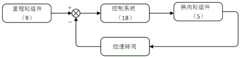
所述控制系统安放在密封仓内,控制系统的输入端与里程轮组件连接,输出端与换向轮组件中的电机连接,控制系统将接收到的里程轮组件测定的清管器实时运行速度与清管器设定运行速度比较,根据清管器实时运行速度与清管器设定运行速度之差控制换向轮组件中电机轴的旋转方向,从而使控速转阀中的扇形齿轮与齿环的齿面组成传动副带动活动翼型扇叶转动,改变所述环形流道的泄流量,使清管器按设定运行速度工作。The control system is placed in the sealed chamber, the input end of the control system is connected to the mileage wheel assembly, and the output end is connected to the motor in the reversing wheel assembly. The control system will receive the real-time running speed of the pipe pig measured by the mileage wheel assembly Compared with the set running speed of the pig, the rotation direction of the motor shaft in the reversing wheel assembly is controlled according to the difference between the real-time running speed of the pig and the set running speed of the pig, so that the sector gear in the speed control rotary valve and the The tooth surface of the gear ring forms a transmission pair to drive the movable airfoil fan blades to rotate, change the discharge flow of the annular flow channel, and make the pig work at the set operating speed.
本发明所述清管器控速装置中,所述里程轮组件由里程轮、编码器、连接架、复位弹簧和底座组成,编码器用于采集清管器的实时运行速度信号,并将实时运行速度信号转化为电信号输送给控制系统,所述连接架的一端与底座铰连,所述编码器安装在连接架的另一端,所述里程轮安装在编码器的转轴上,所述复位弹簧的一端与底座铰连,另一端与连接架铰连。In the pig speed control device of the present invention, the mileage wheel assembly is composed of a mileage wheel, an encoder, a connecting frame, a return spring and a base, and the encoder is used to collect the real-time running speed signal of the pig The speed signal is converted into an electrical signal and sent to the control system. One end of the connecting frame is hinged to the base, the encoder is installed on the other end of the connecting frame, the mileage wheel is installed on the rotating shaft of the encoder, and the return spring One end is hinged with the base, and the other end is hinged with the connecting frame.
本发明所述清管器控速装置中,所述前皮碗组件由前支撑皮碗、前隔板和前驱动皮碗组成,所述后皮碗组件由后支撑皮碗、后隔板和后驱动皮碗组成。In the pig speed control device of the present invention, the front cup assembly is composed of a front supporting cup, a front partition and a front driving cup, and the rear cup assembly is composed of a rear support cup, a rear partition and The rear drive cup is composed.
本发明所述清管器控速装置中,所述控制系统为可编程逻辑控制器(Programmable Logic Controller,简称PLC)。In the pig speed control device of the present invention, the control system is a programmable logic controller (Programmable Logic Controller, PLC for short).
本发明所述清管器控速装置中,所述周向控制机构的换向轮组件中的电机优选步进电机。In the pig speed control device of the present invention, the motor in the reversing wheel assembly of the circumferential control mechanism is preferably a stepping motor.
本发明所述清管器控速方法使用的控速装置的工作原理如下:The working principle of the speed control device used in the pig speed control method of the present invention is as follows:
根据所清洁的管道需要,设定清管器的运行速度范围。当里程轮组件中的编码器检测到清管器的运行速度低于设定速度下限时,控制系统发出指令使控速转阀中周向控制机构的换向轮组件中的电机作顺时针转动,带动换向轮组件整体转向,在被清洁管道内做顺时针螺旋曲线运动,从而带动周向控制机构的安装环和齿环相对清管器做顺时针圆周转动,在齿环的带动下,周向控制机构的各扇形齿轮带着与其连接的活动翼型扇叶转动,将控速转阀的环形流道逐渐关闭,导致环形流道的泄流量逐渐减小,使清管器加速。当里程轮组件中的编码器检测到清管器的运行速度高于设定速度上限时,控制系统发出指令使控速转阀中周向控制机构的换向轮组件中的电机作逆时针转动,带动换向轮组件整体转向,在被清洁管道内做逆时针螺旋曲线运动,从而带动周向控制机构的安装环和齿环相对清管器做逆时针圆周转动,在齿环的带动下,周向控制机构的各扇形齿轮带着与其连接的活动翼型扇叶转动,将控速转阀的环形流道逐渐打开,导致环形流道的泄流量逐渐增大,使清管器减速。当里程轮组件中的编码器检测到清管器的运行速度介于设定速度的上限与下限之间时,控速转阀中周向控制机构的换向轮组件中的电机处于非工作状态,控速转阀中各活动翼型扇叶的开度不变,此时换向轮组件中的摩擦轮保持与被清洁管道平行的方向,靠摩擦轮的侧向摩擦力保持控速转阀中各活动翼型扇叶的开度。Set the operating speed range of the pig according to the needs of the pipeline to be cleaned. When the encoder in the mileage wheel assembly detects that the running speed of the pig is lower than the lower limit of the set speed, the control system sends an instruction to make the motor in the reversing wheel assembly of the circumferential control mechanism in the speed control rotary valve rotate clockwise , to drive the reversing wheel assembly to turn as a whole, to make a clockwise helical curve movement in the pipe to be cleaned, thereby driving the installation ring and the gear ring of the circumferential control mechanism to rotate clockwise relative to the pig. Driven by the gear ring, The sector gears of the circumferential control mechanism rotate with the movable airfoil blades connected to it, gradually closing the annular flow passage of the speed control rotary valve, resulting in a gradual decrease in the discharge flow of the annular flow passage, and accelerating the pig. When the encoder in the mileage wheel assembly detects that the running speed of the pig is higher than the set speed upper limit, the control system sends an instruction to make the motor in the reversing wheel assembly of the circumferential control mechanism in the speed control rotary valve rotate counterclockwise , to drive the reversing wheel assembly to turn as a whole, and make a counterclockwise spiral curve movement in the cleaned pipeline, thereby driving the installation ring and the gear ring of the circumferential control mechanism to rotate counterclockwise with respect to the pig. Driven by the gear ring, The sector gears of the circumferential control mechanism rotate with the movable airfoil blades connected to it, gradually opening the annular flow channel of the speed control rotary valve, resulting in the gradual increase of the discharge flow of the annular flow channel, and decelerating the pig. When the encoder in the mileage wheel assembly detects that the running speed of the pig is between the upper limit and the lower limit of the set speed, the motor in the reversing wheel assembly of the circumferential control mechanism in the speed control rotary valve is in a non-working state , the opening of each movable airfoil fan blade in the speed control rotary valve remains unchanged. At this time, the friction wheel in the reversing wheel assembly maintains a direction parallel to the pipe to be cleaned, and the speed control rotary valve is maintained by the lateral friction of the friction wheel. The opening of each movable airfoil blade in the
本发明具有以下有益效果:The present invention has the following beneficial effects:
1、由于控速转阀由活动翼型扇叶和周向控制机构组成,活动翼型扇叶和周向控制机构的结构及与外骨架、内骨架、密封仓的组合方式,有效解决了现有清管器泄流阀存在的问题,控速转阀不仅工作稳定,而且在控制系统的控制下,便于调整清管器的运行速度,满足清管器的控速要求。1. Since the speed control rotary valve is composed of a movable airfoil fan blade and a circumferential control mechanism, the structure of the movable airfoil fan blade and the circumferential control mechanism and the combination with the outer skeleton, inner skeleton, and sealed chamber effectively solve the current problem. There is a problem with the pig discharge valve, and the speed control rotary valve not only works stably, but also facilitates adjustment of the running speed of the pig under the control of the control system to meet the speed control requirements of the pig.
2、控速转阀中周向控制机构的结构使控速转阀的操作力矩大大提升,同时减少了运行过程中的电力损耗,使清管器在大口径、高压长输天然气管道中的速度控制效率明显提高。2. The structure of the circumferential control mechanism in the speed control rotary valve greatly improves the operating torque of the speed control rotary valve, and at the same time reduces the power loss during operation, making the speed of the pig in the large-diameter, high-pressure long-distance natural gas pipeline The control efficiency is obviously improved.
3、控速转阀中活动翼型扇叶使流体的绕流阻力大大减小,不仅降低了清管过程中的能量损耗,同时也减小了局部振动,使清管器的运行更加平稳。3. The movable airfoil blades in the speed control rotary valve greatly reduce the flow resistance of the fluid, which not only reduces the energy loss during the pigging process, but also reduces the local vibration, making the operation of the pig more stable.
4、由于内骨架位于外骨架的内孔中,密封仓安装在内骨架上,控制系统安放在密封仓内,因而减小了清管器的长度,提高了清管器的弯道通过性。4. Since the inner frame is located in the inner hole of the outer frame, the sealing chamber is installed on the inner frame, and the control system is placed in the sealing chamber, thus reducing the length of the pig and improving the bend passability of the pig.
附图说明:Description of the drawings:
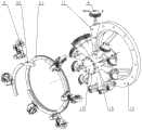
图 1 为本发明所述清管器控速装置的外形结构三维示意图。Fig. 1 is a three-dimensional schematic diagram of the shape and structure of the pig speed control device of the present invention.
图 2 为本发明所述清管器控速装置的剖视图,该图还表示出了清管器控速装置在被清洁管道中的放置方式。Fig. 2 is a cross-sectional view of the speed control device of the pig according to the present invention, which also shows the placement of the speed control device of the pig in the pipeline to be cleaned.
图 3 为本发明所述清管器控速装置中控速转阀的三维爆炸视图。Fig. 3 is a three-dimensional exploded view of the speed control rotary valve in the pig speed control device according to the present invention.
图 4 为本发明所述清管器控速装置中里程轮组件的结构示意图。Fig. 4 is a structural schematic diagram of the mileage wheel assembly in the speed control device of the pig according to the present invention.
图 5 为本发明所述清管器控速装置中换向轮组件的结构示意图。Fig. 5 is a structural schematic diagram of the reversing wheel assembly in the speed control device of the pig according to the present invention.
图 6 为图5的俯视图。Figure 6 is a top view of Figure 5.
图 7 为本发明所述清管器控速装置中控速转阀的活动翼型扇叶的结构示意图。Fig. 7 is a structural schematic diagram of the movable airfoil fan blade of the speed control rotary valve in the pig speed control device according to the present invention.
图 8 为图7的侧视图。Figure 8 is a side view of Figure 7.
图 9 为图7的俯视图。Figure 9 is a top view of Figure 7.
图 10 为本发明所述清管器控速装置中内骨架的结构示意图。Fig. 10 is a schematic structural view of the inner skeleton of the speed control device of the pig according to the present invention.
图 11 为本发明所述清管器控速装置中密封仓的前仓体的结构示意图。Fig. 11 is a schematic structural view of the front chamber body of the sealed chamber in the pig speed control device according to the present invention.
图 12 为本发明所述清管器控速装置的控制框图。Fig. 12 is a control block diagram of the pig speed control device of the present invention.
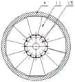
图 13 为本发明所述清管器控速装置中控速转阀的环形流道处于完全打开状态的示意图。Fig. 13 is a schematic diagram of the annular flow channel of the speed control rotary valve in the pig speed control device of the present invention in a fully open state.
图 14 为本发明所述清管器控速装置中控速转阀的环形流道处于部分打开状态的示意图。Fig. 14 is a schematic diagram of the annular flow channel of the speed control rotary valve in the pig speed control device according to the present invention being partially opened.
图 15 为本发明所述清管器控速装置中控速转阀的环形流道处于完全关闭状态的示意图。Fig. 15 is a schematic diagram of the annular flow channel of the speed control rotary valve in the pig speed control device of the present invention in a completely closed state.
图中, 1- 防撞支架;2- 前支撑皮碗;3- 前驱动皮碗;4- 外骨架;4-1- 第一安装环;4-2- 第二安装环;4-3- 环形导轨;4-4- 通孔;5- 换向轮组件;6-扇形齿轮; 7- 后支撑皮碗; 8- 后驱动皮碗;9- 里程轮组件;9-1- 里程轮;9-2- 编码器;9-3-连接架;9-4-复位弹簧;9-5- 底座;10- 前隔板;11- 活动翼型扇叶;11-1- 轴头;11-2-第二轴颈;11-3-轴环;11-4- 翼型叶片;11-5- 第一轴颈;12- 后隔板;13- 内骨架;13-1-半圆形槽式支座;13-2-前端法兰;13-3-支撑梁;13-4-后端法兰;13-5-缺口;14- 被清洁管道;15-前盖板;16-前仓体;16-1- U型槽;17- 后仓体;18-控制系统;19-后盖板;20-安装环;21- 齿环;22-第一支架;23-第二支架;24- 摩擦轮;25- 轮轴;26- 第三支架;27-螺栓;28- 电机;29-弹簧轴;30- 螺母;31- 减震弹簧;32- 从动齿轮;33- 主动齿轮;34- 电机轴。In the figure, 1- anti-collision bracket; 2- front support cup; 3- front drive cup; 4- outer frame; 4-1- first installation ring; 4-2- second installation ring; 4-3- Ring guide rail; 4-4- through hole; 5- reversing wheel assembly; 6- sector gear; 7- rear support cup; 8- rear drive cup; 9- mileage wheel assembly; 9-1- mileage wheel; 9 -2- Encoder; 9-3- Connecting frame; 9-4- Return spring; 9-5- Base; 10- Front partition; 11- Movable airfoil fan blade; -Second journal; 11-3-collar; 11-4-airfoil blade; 11-5-first journal; 12-rear partition; 13-inner frame; 13-1-semicircular groove Support; 13-2-front flange; 13-3-support beam; 13-4-rear flange; 13-5-notch; 14-pipe to be cleaned; 15-front cover; 16-front warehouse body ;16-1-U-shaped groove; 17-rear warehouse body; 18-control system; 19-rear cover; 20-installation ring; 21-gear ring; Friction wheel; 25- axle; 26- the third support; 27- bolt; 28- motor; 29- spring shaft; 30- nut; 31- damping spring; 32- driven gear; 33- driving gear; 34- motor axis.
具体实施方式:Detailed ways:
下面通过实施例并结合附图对本发明所述清管器控速方法使用的控速装置的结构作进一步说明。下述实施例中,可编程逻辑控制器、编码器、步进电机通过市场购买。The structure of the speed control device used in the pig speed control method according to the present invention will be further described below through examples and in conjunction with the accompanying drawings. In the following embodiments, programmable logic controllers, encoders, and stepper motors are purchased from the market.
本实施例中,清管器控速装置如图1、图2所示,包括外骨架4、内骨架13、防撞支架1、前皮碗组件、后皮碗组件、里程轮组件9、控速转阀、控制系统18和用于安放控制系统的密封仓。In this embodiment, the pig speed control device is shown in Figure 1 and Figure 2, including an
所述控速转阀如图3所示,由活动翼型扇叶11和周向控制机构组成;活动翼型扇叶11如图7、图8、图9所示,由翼型叶片11-4及位于翼型叶片11-4一端的第一轴颈11-5,位于翼型叶片11-4另一端的轴环11-3、第二轴颈11-2和轴头11-1构成,翼型叶片11-4呈扇形展开,截面采用NACA0012对称翼型,活动翼型扇叶11的数量为十二个;周向控制机构由换向轮组件5、安装环20、齿环21和扇形齿轮6组成(见图3),换向轮组件5为六套,各套换向轮组件结构相同,均包括第一支架22、第二支架23、第三支架26、摩擦轮24、轮轴25、电机28、螺栓27、弹簧轴29、减震弹簧31、从动齿轮32和主动齿轮33(见图5、图6),所述电机28为步进电机,安装在第一支架22上,所述主动齿轮33安装在电机轴34上,所述从动齿轮32与主动齿轮33组成齿轮传动副,所述第二支架23与从动齿轮32的安装轴固连,所述第三支架26通过螺栓27与第二支架23铰连,所述减震弹簧31通过弹簧轴29和螺母30安装在第二支架23上且第二支架23与第三支架26套装在弹簧轴的一端并通过螺母定位,所述摩擦轮24通过轮轴25安装在第三支架26上;安装环20是由三个圆弧形件组合形成的圆环,齿环21是由两个圆弧形齿件组合形成的一侧环面为齿面的圆环,扇形齿轮6的数量与活动翼型扇叶11的数量相同,各扇形齿轮6的端面上设置有与活动翼型扇叶11组合的通孔,各扇形齿轮6与齿环21的齿面组成传动副。The speed control rotary valve is shown in Fig. 3, and is made up of movable airfoil fan blade 11 and the circumferential control mechanism; Movable airfoil fan blade 11 is shown in Fig. 7, Fig. 8, Fig. 4 and the first journal 11-5 located at one end of the airfoil blade 11-4, the collar 11-3 located at the other end of the airfoil blade 11-4, the second journal 11-2 and the shaft head 11-1, The airfoil blades 11-4 are fan-shaped, the cross-section adopts NACA0012 symmetrical airfoil, and the number of movable airfoil blades 11 is twelve; the circumferential control mechanism consists of the reversing wheel assembly 5, the installation ring 20, the gear ring 21 and the fan-shaped The gear 6 is composed of (see Figure 3), the reversing wheel assembly 5 is six sets, and each set of reversing wheel assembly has the same structure, including a first bracket 22, a second bracket 23, a third bracket 26, a friction wheel 24, and a wheel shaft 25 , motor 28, bolt 27, spring shaft 29, damping spring 31, driven gear 32 and driving gear 33 (see Fig. 5, Fig. 6), described motor 28 is a stepper motor, is installed on the first support 22, The driving gear 33 is installed on the motor shaft 34, the driven gear 32 and the driving gear 33 form a gear transmission pair, the second bracket 23 is fixedly connected with the installation shaft of the driven gear 32, and the third bracket 26 Hinged with the second bracket 23 by the bolt 27, the damping spring 31 is installed on the second bracket 23 by the spring shaft 29 and the nut 30 and the second bracket 23 and the third bracket 26 are sleeved on one end of the spring shaft and passed through the nut Positioning, the friction wheel 24 is installed on the third bracket 26 through the wheel shaft 25; the mounting ring 20 is a ring formed by combining three arc-shaped parts, and the gear ring 21 is formed by combining two arc-shaped tooth parts The ring surface on one side is a circular ring with a tooth surface. The number of sector gears 6 is the same as the number of
所述外骨架4为圆筒体(见图1、图2),总长为1000mm、内径为430mm、外径为470mm,该圆筒体的前部段外壁焊接有环绕外壁的第一安装环4-1,后部段外壁焊接有环绕外壁的第二安装环4-2,中后部段外壁焊接有与控速转阀中的安装环20和齿环21组合的环形导轨4-3,在环形导轨4-3之后,沿圆筒体周向设置有与控速转阀中活动翼型扇叶11数量相同且均匀分布的凸台,各凸台的中心部位设置有供活动翼型扇叶11的轴环11-3、第二轴颈11-2和轴头11-1穿过的通孔4-4。The
所述内骨架13如图10所示,由半圆形槽式支座13-1、前端法兰13-2、后端法兰13-4及用于将前端法兰13-2和后端法兰13-4组合成一体的支撑梁13-3构成;前端法兰13-2的外径小于外骨架4的内径,前端法兰13-2的内孔为前小后大的阶梯孔;后端法兰13-4的外径大于外骨架4的外径,后端法兰13-4的内孔为前大后小的阶梯孔,该阶梯孔前部的大孔与外骨架4的外壁为动配合,后部的小孔孔壁上设置有安装里程轮组件9的缺口13-5;支撑梁13-3的数量为三根,各支撑梁的一端环绕前端法兰13-2的外壁等角度分布并分别与前端法兰13-2的外壁通过焊接固连,各支撑梁13-3的另一端环绕后端法兰13-4的小孔内壁等角度分布并分别与下端法兰13-4的小孔内壁通过焊接固连;半圆形槽式支座13-1的数量与控速转阀中活动翼型扇叶11的数量相同,各半圆形槽式支座13-1安装在前端法兰13-2的前环面同一圆周上且相邻半圆形槽式支座13-1之间的夹角相等。Described
所述密封仓如图2所示,由前仓体16、前盖板15、后仓体17和后盖板19组成;前仓体16如图11所示,为圆筒体,该圆筒体的外径小于内骨架13中前端法兰13-2的外径、内径等于内骨架中前端法兰13-2阶梯孔的小孔孔径,该圆筒体的后端沿圆筒体周向设置有与控速转阀中活动翼型扇叶11数量相同的U形槽16-1,U形槽16-1的宽度与内骨架13中半圆形槽式支座13-1的槽径相同,相邻U形槽16-1之间的夹角相等;后仓体17为圆筒体(见图2),该圆筒体的外壁与内骨架13中前端法兰13-2阶梯孔的大孔为动配合,该圆筒体的前端设置有安装用的连接盘。Described sealed chamber is shown in Figure 2, is made up of
所述里程轮组件9为三组,各组里程轮组件9结构相同,均由里程轮9-1、编码器9-2、连接架9-3、复位弹簧9-4和底座9-5组成(见图4),所述连接架9-3杆状体,其一端与底座9-5铰连,所述编码器9-2安装在连接架9-3的另一端(自由端),所述里程轮9-1安装在编码器9-2的转轴上,所述复位弹簧9-4的一端与底座9-5铰连,另一端与连接架9-3靠近里程轮的部位铰连。The
所述前皮碗组件由前支撑皮碗2、前隔板10和前驱动皮碗3组成(见图2),所述后皮碗组件由后支撑皮碗7、后隔板12和后驱动皮碗8组成(见图2),所述控制系统18为可编程逻辑控制器。The front cup assembly consists of a
上述各部件或构件的组合方式:Combination of the above components or components:
所述前支撑皮碗2、前隔板10和前驱动皮碗3从前至后依次套装在外骨架4的前部段外壁上,前驱动皮碗3与第一安装环4-1接触,所述防撞支架1的一端与外骨架4的前端组合,通过螺纹连接件将防撞支架1和前支撑皮碗2、前隔板10、前驱动皮碗3固定在外骨架4的前部;The front supporting
所述后支撑皮碗7、后隔板12和后驱动皮碗8从前至后一次套装在外骨架4的后部段外壁上,后驱动皮碗8与第二安装环4-2接触,内骨架13的前端法兰13-2位于外骨架4的后部段内孔中,内骨架13的后端法兰13-4通过其阶梯孔前部的大孔与外骨架4的后端组合,通过螺纹连接件将内骨架13的后端法兰13-4和后支撑皮碗7、后隔板12、后驱动皮碗8固定在外骨架4后部;The
所述密封仓前仓体16的后端安装在内骨架前端法兰13-2的前环面上,前仓体16后端设置的各U形槽16-1与位于前端法兰前环面上的各半圆形槽式支座13-1分别组合成安装各活动翼型扇叶第一轴颈11-5的孔;所述密封仓后仓体17的前端插装在内骨架前端法兰13-2阶梯孔的大孔内,通过螺纹连接件与内骨架13前端法兰13-2固连;所述前盖板15安装在前仓体16的前端将前仓体16封闭,所述后盖板19安装在后仓体17的后端将后仓体17封闭;The rear end of the
所述控速转阀中周向控制机构的安装环20安装在外骨架4所设环形导轨4-3的前环面,周向控制机构的齿环21安装在外骨架4所设环形导轨4-3的后环面,安装环20与齿环21通过螺纹连接件连接后形成整体式结构并可沿所述环形导轨4-3转动;周向控制机构的六套换向轮组件5分别通过该换向轮组件5中的第一支架22与所述安装环20固连,并在安装环20周向均匀布置;控速转阀中各活动翼型扇叶11的第一轴颈11-5分别安装在前仓体16后端所设置U形槽16-1与位于前端法兰13-2前环面上的半圆形槽式支座13-1组合成的孔中,各活动翼型扇叶11的轴环11-3、第二轴颈11-2和轴头11-1分别插入外骨架4环形导轨4-3之后的各通孔4-4,且轴头11-1伸出外骨架4,各活动翼型扇叶11的翼型叶片11-4位于外骨架4内壁与密封仓前仓体16外壁围成的环形流道;周向控制机构的各扇形齿轮6分别安装在各活动翼型扇叶11的轴头11-1上并与齿环21组合;The mounting ring 20 of the circumferential control mechanism in the speed control rotary valve is installed on the front ring surface of the annular guide rail 4-3 provided by the outer frame 4, and the gear ring 21 of the circumferential control mechanism is installed on the annular guide rail 4-3 provided by the outer frame 4 The rear annulus, the mounting ring 20 and the gear ring 21 are connected by threaded connectors to form an integral structure and can rotate along the annular guide rail 4-3; the six sets of reversing wheel assemblies 5 of the circumferential control mechanism pass through the reversing wheel The first bracket 22 in the steering wheel assembly 5 is fixedly connected with the installation ring 20, and is evenly arranged in the circumferential direction of the installation ring 20; the first journals 11-5 of each movable airfoil blade 11 in the speed control rotary valve are respectively Installed in the hole formed by the U-shaped groove 16-1 provided at the rear end of the front warehouse body 16 and the semicircular groove support 13-1 on the front ring surface of the front flange 13-2, each movable airfoil fan The collar 11-3, the second journal 11-2 and the shaft head 11-1 of the leaf 11 are respectively inserted into the through holes 4-4 behind the outer frame 4 annular guide rail 4-3, and the shaft head 11-1 protrudes from the outer frame 4. The airfoil blades 11-4 of each movable
所述三组里程轮组件9分别安装在内骨架13后端法兰13-4所设缺口13-5处并与内骨架13后端法兰13-4连接;The three sets of
所述控制系统18安放在密封仓内,控制系统18的输入端与里程轮组件9中的编码器9-2连接,输出端与换向轮组件5中的电机28连接。The control system 18 is placed in a sealed chamber, the input end of the control system 18 is connected to the encoder 9-2 in the
本实施例中,外骨架4、内骨架13和防撞支架1的制作材料为不锈钢;控速转阀中活动翼型扇叶11的制作材料为不锈钢,安装环20、齿环21和扇形齿轮6的制作材料为普通碳钢,摩擦轮24的制作材料为聚氨酯橡胶;密封仓中前仓体16和后仓体17的制作材料为不锈钢,里程轮组件中里程轮9-1的制作材料为不锈钢;前皮碗组件中前支撑皮碗2和前驱动皮碗3及后皮碗组件中后支撑皮碗7和后驱动皮碗8的制作材料为聚氨酯橡胶,前隔板10和后隔板12的制作材料为聚氨酯橡胶。In this embodiment, the material of the
Claims (5)
Translated fromChinesePriority Applications (1)
| Application Number | Priority Date | Filing Date | Title |
|---|---|---|---|
| CN201710305552.7ACN106903122B (en) | 2017-05-03 | 2017-05-03 | A method for controlling the speed of a pipe cleaner |
Applications Claiming Priority (1)
| Application Number | Priority Date | Filing Date | Title |
|---|---|---|---|
| CN201710305552.7ACN106903122B (en) | 2017-05-03 | 2017-05-03 | A method for controlling the speed of a pipe cleaner |
Publications (2)
| Publication Number | Publication Date |
|---|---|
| CN106903122A CN106903122A (en) | 2017-06-30 |
| CN106903122Btrue CN106903122B (en) | 2023-03-07 |
Family
ID=59210102
Family Applications (1)
| Application Number | Title | Priority Date | Filing Date |
|---|---|---|---|
| CN201710305552.7AExpired - Fee RelatedCN106903122B (en) | 2017-05-03 | 2017-05-03 | A method for controlling the speed of a pipe cleaner |
Country Status (1)
| Country | Link |
|---|---|
| CN (1) | CN106903122B (en) |
Families Citing this family (15)
| Publication number | Priority date | Publication date | Assignee | Title |
|---|---|---|---|---|
| CN109060949A (en)* | 2018-08-14 | 2018-12-21 | 中国石油大学(北京) | Integrated pipe channel detector |
| CN109235628B (en)* | 2018-09-18 | 2023-09-12 | 北京城市排水集团有限责任公司 | Pipeline dredging robot based on wall supporting and connecting rod mechanism and use method thereof |
| CN109226128A (en)* | 2018-10-29 | 2019-01-18 | 西南石油大学 | A kind of vane type pipe cleaner of intelligent speed-control |
| CN110293104B (en)* | 2019-07-23 | 2023-02-28 | 泸州职业技术学院 | Rotary injection pipe cleaner with one-way valve |
| US11396034B2 (en)* | 2019-09-30 | 2022-07-26 | Milwaukee Electric Tool Corporation | Motor control of a drain cleaning machine |
| EP4037872A4 (en) | 2019-10-03 | 2023-12-13 | Milwaukee Electric Tool Corporation | Drain cleaner cable decoupler tool |
| CN110773527A (en)* | 2019-11-06 | 2020-02-11 | 吴学伦 | Wind-force direction bellows cleaning equipment |
| CN218555047U (en) | 2020-02-12 | 2023-03-03 | 米沃奇电动工具公司 | Drain pipe cleaning machine |
| CN111720652B (en)* | 2020-06-30 | 2021-10-15 | 西南石油大学 | A multi-stage speed-adjustable traction device for a pipeline intelligent plugging robot |
| CN112207096B (en)* | 2020-09-26 | 2021-10-29 | 宜宾学院 | A pig speed shock restraining mechanism |
| CN112495956A (en)* | 2020-10-20 | 2021-03-16 | 湖州中福人管业科技有限公司 | A inner wall cleaning device for behind pipeline production operation |
| CN112570396A (en)* | 2020-10-28 | 2021-03-30 | 中国民用航空飞行学院 | Natural gas line pigging robot |
| CN112297025B (en)* | 2020-10-30 | 2023-07-28 | 河南工业大学 | Remote pneumatic conveying pipeline cleaning robot |
| CN115507249B (en)* | 2022-11-03 | 2025-07-11 | 南通理工学院 | A dual-speed fluid-driven pipeline robot power unit |
| CN116772035B (en)* | 2023-08-18 | 2023-12-05 | 沈阳仪表科学研究院有限公司 | Braked speed-control in-pipeline detector carrier |
Citations (7)
| Publication number | Priority date | Publication date | Assignee | Title |
|---|---|---|---|---|
| US5208936A (en)* | 1991-05-09 | 1993-05-11 | Campbell Douglas C | Variable speed pig for pipelines |
| US6190090B1 (en)* | 1995-11-08 | 2001-02-20 | Tuboscope Pipeline Services Canada, Inc. | Apparatus for use in a pipeline |
| CN103042017A (en)* | 2011-10-17 | 2013-04-17 | 中国石油天然气集团公司 | Speed control system actuator for pipeline cleaning and detection device |
| CN103977994A (en)* | 2014-05-23 | 2014-08-13 | 西南石油大学 | Automatic speed adjusting pipe cleaner |
| CN105170582A (en)* | 2015-07-16 | 2015-12-23 | 西华大学 | Rotating brushing type jet flow pipe cleaning device |
| CN105598104A (en)* | 2016-03-16 | 2016-05-25 | 西华大学 | High-speed rotating brush pipe cleaner |
| CN208275898U (en)* | 2017-05-03 | 2018-12-25 | 西华大学 | A kind of pipe cleaner speed-controlling device |
Family Cites Families (2)
| Publication number | Priority date | Publication date | Assignee | Title |
|---|---|---|---|---|
| GB0405310D0 (en)* | 2004-03-09 | 2004-04-21 | Prototech As | Pipeline pig |
| US8650694B2 (en)* | 2008-07-03 | 2014-02-18 | Tdw Delaware, Inc | Speed regulated pipeline pig |
- 2017
- 2017-05-03CNCN201710305552.7Apatent/CN106903122B/ennot_activeExpired - Fee Related
Patent Citations (7)
| Publication number | Priority date | Publication date | Assignee | Title |
|---|---|---|---|---|
| US5208936A (en)* | 1991-05-09 | 1993-05-11 | Campbell Douglas C | Variable speed pig for pipelines |
| US6190090B1 (en)* | 1995-11-08 | 2001-02-20 | Tuboscope Pipeline Services Canada, Inc. | Apparatus for use in a pipeline |
| CN103042017A (en)* | 2011-10-17 | 2013-04-17 | 中国石油天然气集团公司 | Speed control system actuator for pipeline cleaning and detection device |
| CN103977994A (en)* | 2014-05-23 | 2014-08-13 | 西南石油大学 | Automatic speed adjusting pipe cleaner |
| CN105170582A (en)* | 2015-07-16 | 2015-12-23 | 西华大学 | Rotating brushing type jet flow pipe cleaning device |
| CN105598104A (en)* | 2016-03-16 | 2016-05-25 | 西华大学 | High-speed rotating brush pipe cleaner |
| CN208275898U (en)* | 2017-05-03 | 2018-12-25 | 西华大学 | A kind of pipe cleaner speed-controlling device |
Non-Patent Citations (1)
| Title |
|---|
| 油气管道内检测器速度控制系统浅析;王梦瑶等;《机电产品开发与创新》;20130528(第03期);133-135* |
Also Published As
| Publication number | Publication date |
|---|---|
| CN106903122A (en) | 2017-06-30 |
Similar Documents
| Publication | Publication Date | Title |
|---|---|---|
| CN106903122B (en) | A method for controlling the speed of a pipe cleaner | |
| CN206229793U (en) | A kind of adjustable speed wiper and its rate controlling rotary valve | |
| CN1962091B (en) | Diameter changeable pipeline cleaning robot having parallel four-bar mechanism | |
| CN105805485B (en) | A City Gas Pipeline Robot Adapting to Pipeline Shape Changes | |
| CN208066888U (en) | A kind of electromagnetic clutch control adjustable speed wiper | |
| CN109058653A (en) | A kind of adaptation detects the composite drive pipe robot of operating condition more | |
| CN109047933B (en) | A bionic groove processing device for pipeline inner wall coating | |
| CN109209736A (en) | A kind of composite efficient hydraulic turbine | |
| CN206229789U (en) | A kind of adjustable speed wiper and its rate controlling mechanism | |
| CN108131468B (en) | A direct acting bypass valve for pig | |
| CN103711726B (en) | The through-flow pump that part of guide vane body is adjustable | |
| CN107013400B (en) | A kind of hydraulic turbine | |
| CN208275898U (en) | A kind of pipe cleaner speed-controlling device | |
| KR101176008B1 (en) | Variable wing turbine valve | |
| CN110552894A (en) | Shaftless pump and method of use thereof | |
| CN201344337Y (en) | Pipeline moving mechanism | |
| US20240392910A1 (en) | Turbine powered pipeline intervention gadget | |
| CN201781924U (en) | Efficient hot-air tea fixation machine | |
| CN103042017B (en) | Speed control system actuator for pipeline cleaning and detection device | |
| CN112570396A (en) | Natural gas line pigging robot | |
| CN117514563A (en) | Adjustable vane turbine | |
| CN114135683B (en) | Liquid flow control valve | |
| CN202810960U (en) | Jet-propelled reverse worm wheel steam turbine power generation device | |
| CN206515047U (en) | A kind of drive mechanism of dedicated hydraulic swivel joint pilot system | |
| CN208024879U (en) | Direct-acting bypass valve for pipe cleaner |
Legal Events
| Date | Code | Title | Description |
|---|---|---|---|
| PB01 | Publication | ||
| PB01 | Publication | ||
| SE01 | Entry into force of request for substantive examination | ||
| SE01 | Entry into force of request for substantive examination | ||
| GR01 | Patent grant | ||
| GR01 | Patent grant | ||
| CF01 | Termination of patent right due to non-payment of annual fee | Granted publication date:20230307 | |
| CF01 | Termination of patent right due to non-payment of annual fee |