CN106848325B - Secondary battery pole piece, preparation method thereof and winding type battery cell - Google Patents
Secondary battery pole piece, preparation method thereof and winding type battery cellDownload PDFInfo
- Publication number
- CN106848325B CN106848325BCN201710081466.2ACN201710081466ACN106848325BCN 106848325 BCN106848325 BCN 106848325BCN 201710081466 ACN201710081466 ACN 201710081466ACN 106848325 BCN106848325 BCN 106848325B
- Authority
- CN
- China
- Prior art keywords
- pole piece
- coating area
- current collector
- area
- sided
- Prior art date
- Legal status (The legal status is an assumption and is not a legal conclusion. Google has not performed a legal analysis and makes no representation as to the accuracy of the status listed.)
- Active
Links
Images


Classifications
- H—ELECTRICITY
- H01—ELECTRIC ELEMENTS
- H01M—PROCESSES OR MEANS, e.g. BATTERIES, FOR THE DIRECT CONVERSION OF CHEMICAL ENERGY INTO ELECTRICAL ENERGY
- H01M4/00—Electrodes
- H01M4/02—Electrodes composed of, or comprising, active material
- H01M4/64—Carriers or collectors
- H01M4/66—Selection of materials
- H01M4/665—Composites
- H01M4/667—Composites in the form of layers, e.g. coatings
- B—PERFORMING OPERATIONS; TRANSPORTING
- B60—VEHICLES IN GENERAL
- B60L—PROPULSION OF ELECTRICALLY-PROPELLED VEHICLES; SUPPLYING ELECTRIC POWER FOR AUXILIARY EQUIPMENT OF ELECTRICALLY-PROPELLED VEHICLES; ELECTRODYNAMIC BRAKE SYSTEMS FOR VEHICLES IN GENERAL; MAGNETIC SUSPENSION OR LEVITATION FOR VEHICLES; MONITORING OPERATING VARIABLES OF ELECTRICALLY-PROPELLED VEHICLES; ELECTRIC SAFETY DEVICES FOR ELECTRICALLY-PROPELLED VEHICLES
- B60L50/00—Electric propulsion with power supplied within the vehicle
- B60L50/50—Electric propulsion with power supplied within the vehicle using propulsion power supplied by batteries or fuel cells
- B60L50/60—Electric propulsion with power supplied within the vehicle using propulsion power supplied by batteries or fuel cells using power supplied by batteries
- B60L50/64—Constructional details of batteries specially adapted for electric vehicles
- H—ELECTRICITY
- H01—ELECTRIC ELEMENTS
- H01M—PROCESSES OR MEANS, e.g. BATTERIES, FOR THE DIRECT CONVERSION OF CHEMICAL ENERGY INTO ELECTRICAL ENERGY
- H01M10/00—Secondary cells; Manufacture thereof
- H01M10/05—Accumulators with non-aqueous electrolyte
- H01M10/052—Li-accumulators
- H01M10/0525—Rocking-chair batteries, i.e. batteries with lithium insertion or intercalation in both electrodes; Lithium-ion batteries
- H—ELECTRICITY
- H01—ELECTRIC ELEMENTS
- H01M—PROCESSES OR MEANS, e.g. BATTERIES, FOR THE DIRECT CONVERSION OF CHEMICAL ENERGY INTO ELECTRICAL ENERGY
- H01M10/00—Secondary cells; Manufacture thereof
- H01M10/05—Accumulators with non-aqueous electrolyte
- H01M10/058—Construction or manufacture
- H01M10/0587—Construction or manufacture of accumulators having only wound construction elements, i.e. wound positive electrodes, wound negative electrodes and wound separators
- H—ELECTRICITY
- H01—ELECTRIC ELEMENTS
- H01M—PROCESSES OR MEANS, e.g. BATTERIES, FOR THE DIRECT CONVERSION OF CHEMICAL ENERGY INTO ELECTRICAL ENERGY
- H01M4/00—Electrodes
- H01M4/02—Electrodes composed of, or comprising, active material
- H01M4/13—Electrodes for accumulators with non-aqueous electrolyte, e.g. for lithium-accumulators; Processes of manufacture thereof
- H01M4/139—Processes of manufacture
- Y—GENERAL TAGGING OF NEW TECHNOLOGICAL DEVELOPMENTS; GENERAL TAGGING OF CROSS-SECTIONAL TECHNOLOGIES SPANNING OVER SEVERAL SECTIONS OF THE IPC; TECHNICAL SUBJECTS COVERED BY FORMER USPC CROSS-REFERENCE ART COLLECTIONS [XRACs] AND DIGESTS
- Y02—TECHNOLOGIES OR APPLICATIONS FOR MITIGATION OR ADAPTATION AGAINST CLIMATE CHANGE
- Y02E—REDUCTION OF GREENHOUSE GAS [GHG] EMISSIONS, RELATED TO ENERGY GENERATION, TRANSMISSION OR DISTRIBUTION
- Y02E60/00—Enabling technologies; Technologies with a potential or indirect contribution to GHG emissions mitigation
- Y02E60/10—Energy storage using batteries
- Y—GENERAL TAGGING OF NEW TECHNOLOGICAL DEVELOPMENTS; GENERAL TAGGING OF CROSS-SECTIONAL TECHNOLOGIES SPANNING OVER SEVERAL SECTIONS OF THE IPC; TECHNICAL SUBJECTS COVERED BY FORMER USPC CROSS-REFERENCE ART COLLECTIONS [XRACs] AND DIGESTS
- Y02—TECHNOLOGIES OR APPLICATIONS FOR MITIGATION OR ADAPTATION AGAINST CLIMATE CHANGE
- Y02P—CLIMATE CHANGE MITIGATION TECHNOLOGIES IN THE PRODUCTION OR PROCESSING OF GOODS
- Y02P70/00—Climate change mitigation technologies in the production process for final industrial or consumer products
- Y02P70/50—Manufacturing or production processes characterised by the final manufactured product
- Y—GENERAL TAGGING OF NEW TECHNOLOGICAL DEVELOPMENTS; GENERAL TAGGING OF CROSS-SECTIONAL TECHNOLOGIES SPANNING OVER SEVERAL SECTIONS OF THE IPC; TECHNICAL SUBJECTS COVERED BY FORMER USPC CROSS-REFERENCE ART COLLECTIONS [XRACs] AND DIGESTS
- Y02—TECHNOLOGIES OR APPLICATIONS FOR MITIGATION OR ADAPTATION AGAINST CLIMATE CHANGE
- Y02T—CLIMATE CHANGE MITIGATION TECHNOLOGIES RELATED TO TRANSPORTATION
- Y02T10/00—Road transport of goods or passengers
- Y02T10/60—Other road transportation technologies with climate change mitigation effect
- Y02T10/70—Energy storage systems for electromobility, e.g. batteries
Landscapes
- Engineering & Computer Science (AREA)
- Chemical & Material Sciences (AREA)
- Chemical Kinetics & Catalysis (AREA)
- Electrochemistry (AREA)
- General Chemical & Material Sciences (AREA)
- Manufacturing & Machinery (AREA)
- Materials Engineering (AREA)
- Life Sciences & Earth Sciences (AREA)
- Composite Materials (AREA)
- Sustainable Development (AREA)
- Sustainable Energy (AREA)
- Power Engineering (AREA)
- Transportation (AREA)
- Mechanical Engineering (AREA)
- Battery Electrode And Active Subsutance (AREA)
- Secondary Cells (AREA)
Abstract
Description
Translated fromChinese技术领域technical field
本申请涉及二次电池技术领域,具体讲,涉及一种二次电池极片,其制备方法,及使用该极片的卷绕式电芯。The present application relates to the technical field of secondary batteries, and in particular, to a secondary battery pole piece, a preparation method thereof, and a wound battery cell using the pole piece.
背景枝术background branch
众所周知,锂离子电池在动力汽车领域有着广阔的应用前景,三元材料(Vs.LFP和LMO等)也因其具有较高的能量密度而备受青睐。但是,随着消费群体对新能源汽车更高更优的追求,目前普通能量密度的电芯已经不能满足市场需求,需要开发具有更高能量密度和更长续航里程的锂离子电芯。传统的方法是从材料体系出发,如:发展高镍正极材料、硅负极材料、采用包覆的方法、研发高压密等等。但是,这些方法开发周期较长,短期内不能输出可靠稳定的数据与方案。所以,基于客户需求和时间的局限性及化学体系、机械、制造等方面的平衡,通过改进极片涂布方式,可以在容量不变的前提下降低群裕度,或者在群裕度不变的条件下节省电池内部空间,进一步提高容量和能量密度,推动高能量密度电芯的应用和电动汽车的发展。As we all know, lithium-ion batteries have broad application prospects in the field of power vehicles, and ternary materials (Vs.LFP and LMO, etc.) are also favored because of their high energy density. However, with the pursuit of higher and better new energy vehicles by consumer groups, the current ordinary energy density cells can no longer meet the market demand, and it is necessary to develop lithium-ion cells with higher energy density and longer cruising range. The traditional method is to start from the material system, such as: the development of high nickel cathode materials, silicon anode materials, the use of coating methods, the development of high density and so on. However, these methods have a long development cycle and cannot output reliable and stable data and solutions in the short term. Therefore, based on customer needs and time constraints and the balance of chemical systems, machinery, manufacturing, etc., by improving the coating method of the pole piece, the group margin can be reduced on the premise of the same capacity, or the group margin can be kept unchanged. It can save the internal space of the battery under the best conditions, further improve the capacity and energy density, and promote the application of high energy density cells and the development of electric vehicles.
鉴于此,特提出本申请。In view of this, this application is hereby made.
发明内容SUMMARY OF THE INVENTION
本申请的首要发明目的在于提出一种二次电池极片。The primary purpose of the invention of the present application is to provide a secondary battery pole piece.
本申请的第二发明目的在于提出该二次电池极片的制备方法。The purpose of the second invention of the present application is to propose a method for preparing the pole piece of the secondary battery.
本申请的第三发明目的在于提出使用该二次电池极片的卷绕式电芯。The object of the third invention of the present application is to propose a wound cell using the secondary battery pole piece.
为了完成本申请的目的,采用的技术方案为:In order to complete the purpose of this application, the technical scheme adopted is:
本申请涉及一种二次电池极片,包括集流体、活性物质层和多个极耳,多个所述极耳沿所述集流体的宽度方向从所述集流体突出;所述集流体包括双面涂覆区、第一单面涂覆区和第二单面涂覆区,所述第一单面涂覆区和所述第二单面涂覆区位于所述集流体相对的两个表面上,且所述第一单面涂覆区和所述第二单面涂覆区均与所述双面涂覆区邻接,所述活性物质层设置于所述双面涂覆区的相对的两个表面,以及所述第一单面涂覆区和所述第二单面涂覆区,多个所述极耳仅位于所述双面涂覆区。The present application relates to a pole piece for a secondary battery, comprising a current collector, an active material layer and a plurality of tabs, the plurality of tabs protruding from the current collector along a width direction of the current collector; the current collector includes A double-sided coating zone, a first single-sided coating zone and a second single-sided coating zone, the first single-sided coating zone and the second single-sided coating zone are located at two opposite sides of the current collector on the surface, and both the first single-sided coating area and the second single-sided coating area are adjacent to the double-sided coating area, and the active material layer is arranged on the opposite side of the double-sided coating area. The two surfaces of the , as well as the first single-side coating area and the second single-side coating area, a plurality of the tabs are only located in the double-side coating area.
优选地,沿所述集流体的长度方向,在所述集流体的至少一端设有空箔区。Preferably, along the length direction of the current collector, at least one end of the current collector is provided with an empty foil area.
优选地,沿所述集流体的宽度方向,在所述第一单面涂覆区和所述第二单面涂覆区设有多个延伸部。Preferably, along the width direction of the current collector, a plurality of extension parts are provided in the first single-side coating area and the second single-side coating area.
优选地,多个所述延伸部的高度为0.5~1mm。Preferably, the height of the plurality of extension parts is 0.5˜1 mm.
本申请还涉及一种二次电池极片的制备方法,至少包括以下步骤:The present application also relates to a method for preparing a pole piece of a secondary battery, comprising at least the following steps:
(1)在集流体的一面上间歇涂布含有活性物质的浆料,并将沿所述集流体的宽度方向上的至少一侧作为用于加工极耳的预留区;活性物质涂覆区的起点分别为a1~n,终点分别为b1~n,涂覆区之间的距离为N1~n,n≥1且n为整数;(1) Intermittently coat a slurry containing an active material on one side of the current collector, and use at least one side along the width direction of the current collector as a reserved area for processing the tabs; the active material coating area The starting points are a1 ~n respectively, the end points are b1 ~n respectively, the distance between the coating areas is N1 ~n , n≥1 and n is an integer;
(2)在所述集流体的另一面上间歇涂布含有活性物质的浆料,活性物质涂覆区的起点为c1~n,终点分别为d1~n;沿所述集流体的长度方向,在用于形成一个二次电池极片的长度范围内,an与dn之间的距离为L1并形成第一单面涂覆区,cn与bn之间的距离为L2并形成第二单面涂覆区;L1、L2均小于an与bn之间的距离且均小于Nn,bn和dn之间的距离为L3并形成双面涂覆区;所述第一单面涂覆区和所述第二单面涂覆区分别位于所述双面涂覆区的两侧;(2) intermittently coating the slurry containing the active material on the other side of the current collector, the starting point of the active material coating area is c1 ~n , and the end points are d1 ~n respectively; along the length of the current collector Direction, within the length range used to form a secondary battery pole piece, the distance between an and dnis L1 and forms the first single-sided coating area, and the distance between cn andbn is L2 and A second single-sided coating area is formed; L1 and L2 are both smaller than the distance between an andbn and are both smaller thanNn , and the distance betweenbn and dnis L3 and a double-sided coating area is formed; the The first single-sided coating area and the second single-sided coating area are respectively located on both sides of the double-sided coating area;
(3)在用于加工极耳的预留区内进行多极耳加工,并切除所述第一单面涂覆区和所述第二单面涂覆区的极耳;(3) carrying out multi-pole tab processing in the reserved area for processing the tabs, and cutting off the tabs of the first single-sided coating area and the second single-sided coating area;
(4)沿集流体宽度方向上,在间歇涂布形成的空箔区进行切割,形成二次电池极片。(4) Cutting along the width direction of the current collector in the empty foil area formed by intermittent coating to form a secondary battery pole piece.
优选地,在切除所述第一单面涂覆区和所述第二单面涂覆区的极耳之前,从所述第一单面涂覆区和所述第二单面涂覆区极耳的根部位置起始设定切割轨迹,然后沿所述切割轨迹切除所述第一单面涂覆区和所述第二单面涂覆区的极耳。Preferably, before cutting off the tabs of the first and second single-sided A cutting trajectory is initially set at the root position of the ear, and then the tabs of the first single-side coating area and the second single-side coating area are cut off along the cutting trajectory.
优选地,所述切割轨迹的高度为0.5~1mm。Preferably, the height of the cutting track is 0.5˜1 mm.
本申请还涉及一种卷绕式电芯,所述卷绕式电芯为由隔膜、第一极片和第二极片卷绕而成的扁平状电芯,所述第一极片和/或第二极片为前述的二次电池极片。The present application also relates to a winding type battery core, which is a flat battery core formed by winding a diaphragm, a first pole piece and a second pole piece, the first pole piece and/ Or the second pole piece is the aforementioned secondary battery pole piece.
优选地,所述二次电池极片以所述第一单面涂覆区为起卷位置进行卷绕,卷绕结束时以所述第二单面涂覆区收尾;在所述扁平状电芯的厚度方向上,所述第二单面涂覆区的末端与所述第二单面涂覆区的起始端重合。Preferably, the secondary battery pole piece is wound with the first single-side coating area as the winding position, and ends with the second single-side coating area at the end of the winding; In the thickness direction of the core, the end of the second single-sided coating region coincides with the starting end of the second single-sided coating region.
优选地,所述卷绕式电芯用于动力汽车电池。Preferably, the wound cell is used in a power vehicle battery.
本申请的技术方案至少具有以下有益的效果:The technical solution of the present application has at least the following beneficial effects:
本申请提供了一种二次电池极片,其包括互相不重叠的第一单面涂覆区和第二单面涂覆区。在保证群裕度不变的前提条件下,可节省电池内部空间,通过在节省的空间增加裸电芯的层数,可以提升容量。在保证设计容量不变的前提条件下,可以降低裸电芯的厚度,从而降低群裕度。同时仅在双面涂覆区设置极耳,解决了极片卷绕时第一单面涂覆区和第二单面涂覆区的极耳翻折严重的问题。The present application provides a secondary battery pole piece, which includes a first single-side coating area and a second single-side coating area that do not overlap each other. On the premise that the group margin remains unchanged, the internal space of the battery can be saved, and the capacity can be increased by increasing the number of layers of bare cells in the saved space. On the premise that the design capacity remains unchanged, the thickness of the bare cell can be reduced, thereby reducing the group margin. At the same time, only the tabs are arranged in the double-sided coating area, which solves the problem of serious folding of the tabs in the first single-sided coating area and the second single-sided coating area when the pole piece is wound.
本申请还提供了该二次电池极片的制备方法,其通过对集流体的两个表面分别进行间歇涂布实现,故称之为双间歇涂布。该方法可以提高涂布的效率。The present application also provides a method for preparing the pole piece of the secondary battery, which is realized by intermittently coating the two surfaces of the current collector respectively, so it is called double intermittent coating. This method can improve the efficiency of coating.
本申请还提供了使用所述二次电池极片的电芯,该电芯适用于大功率的动力汽车电池。在优选的方案中,该电芯以第一单面涂覆区和第二单面涂覆区起卷和收尾,且未涂布区节省的空间可以降低群裕度或者增加极片层数以增加容量。当选用电芯壳体材质为铝壳时,有利于在穿钉测试中避免爆炸起火,提高电芯整体的安全性。The present application also provides a battery cell using the secondary battery pole piece, which is suitable for high-power electric vehicle batteries. In a preferred solution, the cell is rolled up and terminated with the first single-side coating area and the second single-side coating area, and the space saved by the uncoated area can reduce the group margin or increase the number of pole piece layers to Increase capacity. When the battery core shell is made of aluminum, it is beneficial to avoid explosion and fire during the nail penetration test and improve the overall safety of the battery core.
附图说明Description of drawings
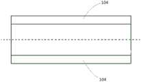
图1为本申请的二次电池极片剖面的结构示意图;1 is a schematic structural diagram of a cross-section of a secondary battery pole piece of the application;
图2为本申请的集流体在加工前的结构示意图;2 is a schematic structural diagram of the current collector of the application before processing;
图3为本申请的集流体涂覆过程示意图;3 is a schematic diagram of the current collector coating process of the application;
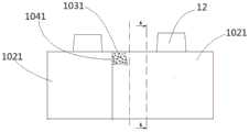
图4为本申请的二次电池极片极耳切割后的示意图;4 is a schematic diagram of the secondary battery electrode tab of the application after cutting;
图5为本申请的卷绕式电芯的示意图;FIG. 5 is a schematic diagram of a wound cell of the application;
图6为图5的A-A线剖视图;Fig. 6 is the A-A line sectional view of Fig. 5;
图7为图6虚线框内部分的放大图。FIG. 7 is an enlarged view of the portion inside the dashed-line frame of FIG. 6 .
其中:in:
1-极片;1-pole piece;
10-集流体;10- collector;
101-A面;1011-第一单面涂覆区;101-A side; 1011-The first single-side coating area;
102-B面;1021-第二单面涂覆区;102-B side; 1021-Second single-side coating area;
1031-双面涂覆区;1031 - Double-sided coating area;
1041-第二单面涂覆区的起始端;1041 - the starting end of the second single-sided coating area;
103-空箔区;103 - empty foil area;
104-预留区;104 - reserved area;
11-活性物质层;11-active material layer;
12-极耳;121-延伸部;12-pole ear; 121-extension part;
2-电芯;2-cell;
21-铜箔;211-负极极耳;21-copper foil; 211-negative electrode tab;
22-铝箔;22-aluminum foil;
23-隔膜;23-diaphragm;
24-负极活性物质层;24- negative electrode active material layer;
25-正极活性物质层。25 - Positive electrode active material layer.
具体实施方式Detailed ways
下面结合具体实施例,进一步阐述本申请。应理解,这些实施例仅用于说明本申请而不用于限制本申请的范围。The present application will be further described below with reference to specific embodiments. It should be understood that these examples are only used to illustrate the present application and not to limit the scope of the present application.
本申请涉及一种二次电池极片1,如图1和图3所示,包括集流体10、活性物质层11和多个极耳12,多个极耳12沿集流体10的宽度方向从集流体10突出。该二次电池极片1的剖面图如图1所示,集流体10包括双面涂覆区1031、第一单面涂覆区1011和第二单面涂覆区1021。The present application relates to a secondary
其中,第一单面涂覆区1011和第二单面涂覆区1021位于集流体10相对的两个表面上,且第一单面涂覆区1011和第二单面涂覆区1021均与双面涂覆区1031邻接。可以将集流体10相对的两个表面定义为A面101和B面102,第一单面涂覆区1011位于A面101,第二单面涂覆区1021位于B面102。此时第一单面涂覆区1011和第二单面涂覆区1021分别位于双面涂覆区1031的两侧,第一单面涂覆区1011和第二单面涂覆区1021相互错开无重叠,因此将这种涂布方式称为双错位间歇涂布。这种涂布方式能够在群裕度不变的条件下可节省电池内部空间,利用节省的空间增加裸电芯的层数,以此提升容量;或者在电池设计容量不变的前提下,降低裸电芯的厚度,降低整个电芯的群裕度。活性物质层11设置于双面涂覆区1031的相对的两个表面,以及第一单面涂覆区1011和第二单面涂覆区1021。Wherein, the first single-
将该极片1与隔膜和其它极片叠加后,在卷绕成电芯的过程中,如果在第一单面涂覆区1011和第二单面涂覆区1021设有极耳12,由于在第一单面涂覆区1011和第二单面涂覆区1021仅有一面涂布活性物质层11,集流体10两面的重量分布不均匀,极耳12容易朝向未涂布活性物质层11的一面发生翻折,且卷绕后容易夹在极片1内,造成安全隐患。虽然可以采用人工将极耳12挑出的传统方式克服这一缺陷,但这种方式效率低下,且极耳12容易撕裂,坏品率极高。本申请研究发现,如果将第一单面涂覆区1011和第二单面涂覆区1021的极耳12切除,可以快速且高效地解决该问题。在本申请的二次电池极片1中,多个极耳12仅位于双面涂覆区1031。After the
在后续过程中需要从整条集流体10上切下单独的极片1,为了不影响第一单面涂覆区1011和第二单面涂覆区1021上涂覆的活性物质层11。可以沿集流体10的长度方向,在集流体10的至少一端设有未涂布活性物质层11的空箔区103,这样在切割时不会影响前后极片1的完整性。具体地,可以在集流体10的两端设置空箔区103,也可以在集流体10的一端设置空箔区103,也可以不设置空箔区103。In the subsequent process,
虽然本申请限定了在第一单面涂覆区1011和第二单面涂覆区1021上没有极耳12,也可以沿集流体10的宽度方向,在第一单面涂覆区1011和第二单面涂覆区1021设置高度为0.5-1mm的多个延伸部121。这些延伸部121可以通过切除第一单面涂覆区1011和第二单面涂覆区1021的极耳12得到。Although the present application defines that there are no
本申请还涉及一种二次电池极片1的制备方法,至少包括以下步骤:The present application also relates to a method for preparing a secondary
(1)在集流体10的一面上间歇涂布含有活性物质的浆料,并将沿集流体10的宽度方向上的至少一侧作为用于加工极耳12的预留区104,如图2所示。活性物质涂覆区的起点分别为a1~n,终点分别为b1~n,涂覆区之间的距离为N1~n,n≥1且n为整数,如图3所示;(1) Intermittently coat a slurry containing an active material on one side of the
(2)在集流体10的另一面上间歇涂布含有活性物质的浆料,活性物质涂覆区的起点为c1~n,终点分别为d1~n;沿集流体10的长度方向,在用于形成一个二次电池极片1的长度范围内,an与dn之间的距离为L1并形成第一单面涂覆区1011,cn与bn之间的距离为L2并形成第二单面涂覆区1021;L1、L2均小于an与bn之间的距离且均小于Nn,bn和dn之间的距离为L3并形成双面涂覆区1031;第一单面涂覆区1011和第二单面涂覆区1021分别位于双面涂覆区1031的两侧;(2) Intermittently coat the other side of the
(3)在用于加工极耳12的预留区104内进行多极耳12加工,并切除第一单面涂覆区1011和第二单面涂覆区1021的极耳12;(3)
(4)沿集流体10宽度方向上,在间歇涂布形成的空箔区103进行切割,形成二次电池极片1。(4) Cutting along the width direction of the
具体地,在步骤(1)中使集流体10的A面101向上,驱动集流体10匀速运动,在集流体10的A面101进行浆料的间隙涂布。将第一次涂布的起点记为a1,当浆料长度达到预定值时停止涂布,将第一次涂布的终点记为b1。集流体10继续运动形成空白带,该空白带的长度即为A面101第一涂覆区和第二涂覆区之间的距离N1,然后进行第二次涂布,将第二次涂布的起点和终点分别记为a2、b2。循环此过程,完成A面101的间隙涂布。图3中的箭头表示集流体10的运动方向。Specifically, in step (1), the
将完成A面101的间隙涂布的集流体10翻面,确保空白的B面102向上,已涂布的A面101向下,反向驱动集流体10匀速运动,然后进行步骤(2),在集流体10的B面102进行浆料的间隙涂布。将第一次涂布的起点记为c1,当浆料长度达到预定值时停止涂布,将第一次涂布的终点记为d1。集流体10继续运动形成空白带,该空白带的长度即为B面102第一涂覆区和第二涂覆区之间的距离M1,然后进行第二次涂布,将第二次涂布的起点和终点分别记为c2、d2。循环此过程,完成B面102的间隙涂布。优选在A面101和B面102上分别进行多次涂布,即n≥2。Turn over the
在步骤(3)中,可通过普通模切或激光模切方式在预留区104进行多极耳加工,成型得到的极耳12间距不一定相等,但应该满足在卷绕成型的裸电芯中,每一层的正极极耳或负极极耳均重合。可以在模切设备上加入单面涂覆区极耳切除刀模,模切后即可除去第一单面涂覆区1011和第二单面涂覆区1021(还可以包括间歇涂布形成的空箔区103)的极耳12,解决单面涂覆区由于极耳12内翻且夹在极片1内导致的安全问题。In step (3), the multi-pole tabs can be processed in the reserved
步骤(3)结束后,如果集流体10是对称设置的,沿集流体10的两条长边方向均设有极耳12和延伸部。可以先沿对称线(图4中的虚线)将集流体10切割,然后进行步骤(4),将整条集流体10分成多个二次电池极片1。After step (3), if the
如果采用上述方式将单面涂覆区的极耳12完全切除,进行切割的位置容易发生拉丝、缺口、掉粉等现象。作为改进,在切除第一单面涂覆区1011和第二单面涂覆区1021的极耳12之前,从第一单面涂覆区1011和第二单面涂覆区1021极耳12的根部位置起始设定切割轨迹,切割轨迹的高度可以为0.5-1mm。然后沿切割轨迹切除第一单面涂覆区1011和第二单面涂覆区1021的极耳12,在切割位置仅留下高度为0.5~1mm的延伸部121,如图4所示。将上述第一单面涂覆区1011和第二单面涂覆区1021具有延伸部121的极片1卷绕后,位于内圈和和外圈的单面涂覆区均没有极耳12翻折,提高了生产效率,降低坏品率。If the
本申请还涉及一种卷绕式电芯,其为由隔膜、第一极片和第二极片卷绕而成的扁平状电芯,其中第一极片和/或第二极片为前述的二次电池极片1。The present application also relates to a wound battery core, which is a flat battery core formed by winding a diaphragm, a first pole piece and a second pole piece, wherein the first pole piece and/or the second pole piece are the aforementioned The secondary
进一步地,如图5所示,二次电池极片1以第一单面涂覆区1011为起卷位置进行卷绕,卷绕结束时以第二单面涂覆区1021收尾。电芯的最内侧和最外层均为集流体10未涂覆的光亮表面。第二单面涂覆区1021的末端与第二单面涂覆区1021的起始端1041重合,这样能够降低群裕度或增加容量。实际卷绕时,隔膜23的长度要长于二次电池极片1,在电芯外部形成单层或多层隔膜23包裹的结构,在图5中未示出。Further, as shown in FIG. 5 , the secondary
图6为图5沿A-A线的剖面图,图6下方带有剖面线的矩形框表示电芯主体,上方多条平行的竖线表示极耳12。图7为图6虚线框内部分的放大图。本实施例中,铜箔21作为负极集流体采用双间歇涂布,沿其长度方向位于两端的第一单面涂覆区1011和第二单面涂覆区1021上仅涂布单层负极活性物质层24。铜箔21中间部分为双面涂覆区1031,两面均涂布有负极活性物质层24。铝箔22作为正极集流体采用连续涂覆,即两面均涂布有正极活性物质层25。FIG. 6 is a cross-sectional view taken along the line A-A in FIG. 5 . The rectangular frame with cross-section lines at the bottom of FIG. 6 represents the main body of the cell, and the upper parallel vertical lines represent the
从图7中可见将铜箔21、隔膜23和铝箔22叠加后形成的卷绕结构。其中最左侧的隔膜23位于卷绕式电芯2最外侧,最右侧的隔膜23位于卷绕式电芯2最内侧。与最左侧的隔膜23相邻的铜箔21所在区域为第二单面涂覆区1021,仅在该铜箔21的内侧设有负极活性物质层24。与最右侧的隔膜23相邻的铜箔21所在区域为第一单面涂覆区1011,仅在该铜箔21的外侧设有负极活性物质层24。在第一单面涂覆区1011和第二单面涂覆区1021上不设置极耳211。图7省略了部分卷绕式电芯2的卷绕结构,省略的部分以虚线表示。铜箔上设有负极极耳211的区域即为双面涂覆区1031。It can be seen from FIG. 7 that the winding structure formed by stacking the
因为动力电芯(EV)体积较大,其极片宽度和长度均为消费类电芯(CE)的几倍或者几十倍,一般外壳采用难以变形的铝壳或钢壳,内部空间利用较显著。其容量和能量密度较大,所以采用双错位间歇涂布对容量或群裕度的贡献更为明显。而消费类电芯体积小,一般采用软包电芯,外壳为容易变形的材质,内部空间利用率本身较高,整体容量较低,虽然与动力电池相比采用双错位间歇涂布比较容易实现,但对容量的贡献并不明显。因此该电芯尤其适用于动力汽车电池。Because the power cell (EV) is large in size, its pole piece width and length are several times or dozens of times that of the consumer cell (CE). Generally, the outer shell is made of aluminum shell or steel shell that is difficult to deform, and the internal space utilization is relatively small. Significantly. Its capacity and energy density are larger, so the contribution of double-dislocation intermittent coating to capacity or group margin is more obvious. Consumer batteries are small in size, generally use soft-packed batteries, and the outer shell is made of easily deformed materials. The utilization rate of internal space itself is high, and the overall capacity is low. Although compared with power batteries, it is easier to use double-displacement intermittent coating. , but the contribution to the capacity is not obvious. Therefore, the cell is especially suitable for power vehicle batteries.
实施例1Example 1
本实施例在电芯负极侧采用双间歇单面涂布工艺,正极侧为传统连续涂布工艺。如果选用正极侧为双间歇涂布工艺,其方法类似。In this embodiment, a double intermittent single-side coating process is used on the negative electrode side of the cell, and a traditional continuous coating process is used on the positive electrode side. If the double batch coating process is selected on the positive side, the method is similar.
正极片的制备(采用连续涂布工艺):Preparation of positive electrode sheet (using continuous coating process):
1、活性材料层的制备1. Preparation of active material layer
将粘接剂聚偏氟乙烯(PVDF)溶解在溶剂N-甲基吡咯烷酮(NMP)中,充分搅拌,然后加入正极活性物质(如钴酸锂、磷酸铁锂、镍钴锰酸锂等)和导电剂Super P,其中重量比为正极活性物质:PVDF:Super P=95:2:3,最后抽真空脱除气泡。用150目不锈钢筛网过滤即得到所需的正极浆料。将得到的正极浆料均匀地涂覆在过渡层上,85℃下干燥,干燥完成后进行冷压裁片,得到正极极片。Dissolve the binder polyvinylidene fluoride (PVDF) in the solvent N-methylpyrrolidone (NMP), stir well, and then add the positive active material (such as lithium cobalt oxide, lithium iron phosphate, lithium nickel cobalt manganese oxide, etc.) and Conducting agent Super P, wherein the weight ratio is positive active material: PVDF: Super P = 95: 2: 3, and finally vacuuming to remove air bubbles. Filter with a 150-mesh stainless steel mesh to obtain the desired positive electrode slurry. The obtained positive electrode slurry was uniformly coated on the transition layer, dried at 85° C., and then cold-pressed and cut into pieces to obtain a positive electrode piece.
负极片的制备(采用双错位间歇涂布工艺):Preparation of negative electrode sheet (using double dislocation intermittent coating process):
将粘结剂丁苯橡胶(SBR)溶解在水中,得到SBR水溶液,然后将人造石墨、Super P和增稠剂羧甲基纤维素钠(CMC)加入SBR水溶液中,其重量比为人造石墨:Super P:CMC2200:SBR=96:1:1:2,搅拌均匀后,在厚度为8μm的铜箔上依次进行A面和B面的间歇涂布,然后在110℃下干燥,冷压并经过模切工序进行极耳成型,切除第一单面涂覆区和第二单面涂覆区的极耳,完成后沿集流体长度方向的中心线进行裁片,在间歇涂布形成的空箔区进行切割,得到图1所示的负极极片。各负极极片的样品编号、涂布层厚度和长度见表1,其中JR为电芯的缩写,例如P1(4JR)的含义为在一个电池壳体内装有4个电芯,每个电芯均采用P1作为负极极片。Binding agent styrene-butadiene rubber (SBR) is dissolved in water to obtain SBR aqueous solution, then artificial graphite, Super P and thickener sodium carboxymethyl cellulose (CMC) are added in the SBR aqueous solution, and its weight ratio is artificial graphite: Super P:CMC2200:SBR=96:1:1:2, after stirring evenly, intermittently coating the A side and the B side on the copper foil with a thickness of 8 μm in turn, then drying at 110 ° C, cold pressing and passing through The die-cutting process performs tab forming, cutting off the tabs of the first single-side coating area and the second single-side coating area, and after completion, cutting along the center line of the length direction of the current collector, and intermittently coating the formed empty foil The region is cut to obtain the negative pole piece shown in FIG. 1 . The sample number, coating layer thickness and length of each negative pole piece are shown in Table 1, where JR is the abbreviation of battery cell. All use P1 as the negative pole piece.
隔膜使用厚度为12μm的聚丙烯(PP)/聚乙烯(PE)/聚丙烯(PP)三层复合多孔膜;The separator uses a polypropylene (PP)/polyethylene (PE)/polypropylene (PP) three-layer composite porous membrane with a thickness of 12 μm;
电解液的制备:Preparation of electrolyte:
将等体积的碳酸乙烯酯(EC)、碳酸甲乙酯(EMC)和碳酸二乙酯(DEC)混合均匀,得到混合溶剂,然后加入六氟磷酸锂(LiPF6),其中LiPF6的浓度为1mol/L。Mix equal volumes of ethylene carbonate (EC), ethyl methyl carbonate (EMC) and diethyl carbonate (DEC) to obtain a mixed solvent, and then add lithium hexafluorophosphate (LiPF6 ), wherein the concentration of LiPF6 is 1mol/L .
将上述正极片、负极片、隔膜通过卷绕工艺形成电芯,然后将电芯放入包装袋内,注入电解液后,经化成、封装、容量等工艺组装成电池。以P1为负极极片,得到的电池记为C1,以P2为负极极片,得到的电池记为C2。以此类推,得到电池样品C1~C11。The above-mentioned positive electrode sheet, negative electrode sheet, and separator are formed into a battery cell through a winding process, and then the battery cell is put into a packaging bag, injected with an electrolyte, and assembled into a battery through processes such as formation, packaging, and capacity. Taking P1 as the negative pole piece, the obtained battery is denoted as C1, and with P2 as the negative pole piece, the obtained battery is denoted as C2. By analogy, battery samples C1 to C11 are obtained.
表1Table 1

对比例1Comparative Example 1
正极极片和隔膜同实施例1,负极极片采用连续涂布方式进行涂布,样品编号、涂布层厚度和长度见表2。The positive pole piece and the separator are the same as in Example 1, and the negative pole piece is coated by continuous coating. The sample number, thickness and length of the coating layer are shown in Table 2.
表2Table 2


测试例1Test Example 1
对实施例1和对比例1的电池样品进行容量和群裕度测试,结果见表3。The battery samples of Example 1 and Comparative Example 1 were tested for capacity and group margin, and the results are shown in Table 3.
其中,容量的测试方式如下:以1C的放电电流放电至下限截止电压,休息5min,以1C的电流恒流充电至上限电压,最后以1C的放电电流放电至下限截止电压,得到电池的实际容量。本实施例中下限截止电压为2.8V,上限电压为4.2V。Among them, the capacity test method is as follows: discharge with a discharge current of 1C to the lower limit cut-off voltage, rest for 5 minutes, charge with a constant current of 1C to the upper limit voltage, and finally discharge with a discharge current of 1C to the lower limit cut-off voltage to obtain the actual capacity of the battery . In this embodiment, the lower limit cut-off voltage is 2.8V, and the upper limit voltage is 4.2V.
群裕度测试方法为:利用厚度测试仪测试卷绕后的电芯厚度,然后用电芯厚度除以电池壳体内部厚度,得到群裕度。The group margin test method is as follows: use a thickness tester to test the thickness of the wound cells, and then divide the cell thickness by the internal thickness of the battery case to obtain the group margin.
表3table 3


对表3的测试结果进行说明。以电池C1和C1’为例,两者的区别在于C1’的负极极片采用连续涂布,涂布层长度等于C1负极极片的第一单面涂覆区长度、第二单面涂覆区长度和双面涂覆区长度之和。选用相同的电池壳体,在群裕度相同的条件下,进行双错位间歇涂布可节省部分电池内部空间,增加裸电芯的层数,进而提高电池容量,因此电池C1与C1’相比容量增加了3.1Ah。The test results in Table 3 will be described. Taking batteries C1 and C1' as an example, the difference between the two is that the negative pole piece of C1' is continuously coated, and the length of the coating layer is equal to the length of the first single-sided coating area and the second single-sided coating of the negative pole piece of C1. The sum of the zone length and the double-sided coated zone length. Using the same battery case, under the condition of the same group margin, double-dislocation intermittent coating can save part of the internal space of the battery, increase the number of layers of bare cells, and then improve the battery capacity. Therefore, the battery C1 is compared with C1'. Capacity increased by 3.1Ah.
以电池C2和C2’为例,两者的区别在于C2’的负极极片采用连续涂布,涂布层长度等于C2负极极片的第一单面涂覆区长度、第二单面涂覆区长度和双面涂覆区长度之和。选用相同的电池壳体,在容量相同的条件下,负极极片长度不变,进行双错位间歇涂布可减少负极极片厚度,进一步减少裸电芯的厚度,进而降低群裕度,因此电池C2与C2’相比群裕度降低了3.1%。Taking batteries C2 and C2' as an example, the difference between the two is that the negative pole piece of C2' is continuously coated, and the length of the coating layer is equal to the length of the first single-sided coating area and the second single-sided coating of the negative pole piece of C2. The sum of the zone length and the double-sided coated zone length. Using the same battery case, under the condition of the same capacity, the length of the negative pole piece remains unchanged. Double-dislocation intermittent coating can reduce the thickness of the negative pole piece, further reduce the thickness of the bare cell, and then reduce the group margin. Therefore, the battery The group margin of C2 is reduced by 3.1% compared to C2'.
群裕度是指电池实际内部截面积与最大内部截面积的比例,也就是填充率。即,将电芯横向切开,其中卷绕式电芯中各种物质的截面积与电池壳体内径包含的面积的比值,可以表征卷绕式电芯的入壳的困难程度、电芯充电膨胀后对壳体的压力等。群裕度的计算方式有两种,分别是:The group margin refers to the ratio of the actual internal cross-sectional area of the battery to the maximum internal cross-sectional area, that is, the filling rate. That is, the cell is cut horizontally, and the ratio of the cross-sectional area of various substances in the wound cell to the area contained in the inner diameter of the battery case can characterize the difficulty of the wound cell into the case, the difficulty of charging the cell Pressure on the shell after expansion, etc. There are two ways to calculate the group margin, which are:


表4Table 4

使用双错位间歇涂布的负极极片对容量或群裕度贡献的理论值计算方法见表4。将单层负极极片冷压后,双面区和单面区的厚度差值定义为负极片节省厚度。即与双面区的厚度相比,使用单面涂布后每层负极极片的节省厚度为x。若冷压后负极极片的回弹率为y%,则回弹后每层负极极片节省的厚度为x*(1+y%),则卷绕后整个裸电芯内圈单面区和外圈单面区共节省厚度为4*x*(1+y%)。若一个电池壳体的壳体总厚度为M,壳体壁厚为m,壳体内裸电芯的个数为N,则所有裸电芯在电池壳体内节约的厚度为N*4x*(1+y%)。The theoretical calculation method of the contribution of the negative pole piece to the capacity or group margin using the double-dislocation intermittently coated negative pole piece is shown in Table 4. After cold-pressing the single-layer negative pole piece, the thickness difference between the double-sided area and the single-sided area is defined as the saving thickness of the negative electrode piece. That is, compared with the thickness of the double-sided area, the saved thickness of each layer of negative pole piece after single-sided coating is x. If the rebound rate of the negative pole piece after cold pressing is y%, the thickness saved by each layer of negative pole piece after springback is x*(1+y%), then the single-sided area of the inner circle of the entire bare cell after winding The total thickness saved with the single-sided area of the outer ring is 4*x*(1+y%). If the total thickness of a battery case is M, the wall thickness of the case is m, and the number of bare cells in the case is N, then the thickness saved by all bare cells in the battery case is N*4x*(1 +y%).
当电池容量保持不变时,则可以节省空间,降低群裕度,群裕度理论降低值为N*4x*(1+y%)/(M-2m)。When the battery capacity remains the same, space can be saved and the group margin can be reduced. The theoretical reduction value of the group margin is N*4x*(1+y%)/(M-2m).
当电芯的群裕度不变时,则可以提升电芯的容量,容量理论提升值为:When the group margin of the cell remains unchanged, the capacity of the cell can be increased. The theoretical increase in capacity is:

其中,未使用双错位间歇涂布的负极极片时电芯的容量为R Ah,隔膜厚度为T1mm,正极极片冷压后厚度为T2mm,负极极片冷压后的厚度为T3mm,单位面积正极极片的涂布重量为C.W.g/mm2,单层正极极片的面积为S mm2,正极材料的理论克容量为G mAh/g。Among them, the capacity of the battery cell is R Ah when the negative pole piece coated with double dislocation intermittent coating is not used, the thickness of the diaphragm is T1mm, the thickness of the positive pole piece after cold pressing is T2mm, the thickness of the negative pole piece after cold pressing is T3mm, and the unit area is The coating weight of the positive electrode piece is CWg/mm2 , the area of the single-layer positive electrode piece is S mm2 , and the theoretical gram capacity of the positive electrode material is G mAh/g.
若x=0.0585,y%=8%,x*(1+y%)=0.06,4x*(1+y%)=0.25272,当N=2时,按上述公式计算,当电池容量不变时,群裕度理论降低值为2%,当电池群裕度不变,容量理论提升值为4%。当N=4时,按上述公式计算,当电池容量不变,群裕度理论降低值为4%,当电池群裕度不变,容量理论提升值为8%。If x=0.0585, y%=8%, x*(1+y%)=0.06, 4x*(1+y%)=0.25272, when N=2, calculate according to the above formula, when the battery capacity is constant , the theoretical reduction value of group margin is 2%, and when the battery group margin remains unchanged, the theoretical increase value of capacity is 4%. When N=4, according to the above formula, when the battery capacity remains unchanged, the theoretical reduction value of the group margin is 4%, and when the battery group margin remains unchanged, the theoretical increase in capacity is 8%.
表5table 5

表5为实际测定的容量或群裕度数据。以群裕度一定,N=2为例,此时群裕度为94.05%;使用连续涂布的负极极片时,电芯的容量值为50.03Ah;使用双错位间歇涂布的负极极片时,电芯的容量值为51.42Ah;对两者做差,得到使用双错位间歇涂布的负极极片对容量的直接贡献值为1.39Ah;用两者的差除以连续涂布的容量值,得到使用双错位间歇涂布的负极极片对容量贡献的百分数为3%。Table 5 shows the actual measured capacity or group margin data. Taking a certain group margin and N=2 as an example, the group margin is 94.05% at this time; when using a continuously coated negative pole piece, the capacity of the cell is 50.03Ah; using a double dislocation intermittently coated negative pole piece When , the capacity value of the cell is 51.42Ah; by making the difference between the two, the direct contribution value of the negative pole piece using double-dislocation intermittent coating to the capacity is 1.39Ah; divide the difference between the two by the capacity of continuous coating value, the percentage contribution to the capacity of the negative pole piece using double dislocation intermittent coating is 3%.
根据能量计算公式Wh=Ah(容量)*V(电压),对于能量密度有两种计算方式:一种是质量能量密度(Wh/kg),指的是单位质量的电池中所储存的能量。另一种是体积能量密度(Wh/L),指的是单位体积电池中所储存的能量。如果单位体积里的容量提升了,则能量提升,能量密度也有所提升。由此可知,采用本申请双间歇单面涂布的技术方案,在群裕度不变的情况下,能够提升能量密度。即固定化学参数和机械件设计,可节省部分电池内部空间,在该空间下可以增加裸电芯的层数,电芯容量可提高2%~8%。According to the energy calculation formula Wh=Ah(capacity)*V(voltage), there are two calculation methods for the energy density: one is the mass energy density (Wh/kg), which refers to the energy stored in the battery per unit mass. The other is volumetric energy density (Wh/L), which refers to the energy stored in a unit volume of battery. If the capacity per unit volume increases, the energy increases and the energy density also increases. It can be seen from this that the energy density can be improved under the condition that the cluster margin remains unchanged by adopting the technical solution of the double intermittent single-side coating of the present application. That is, the fixed chemical parameters and the design of mechanical parts can save part of the internal space of the battery. In this space, the number of layers of the bare cell can be increased, and the capacity of the cell can be increased by 2% to 8%.
反过来,在电芯容量不变的情况下,能够降低群裕度。即固定化学参数和机械件设计,使用单面涂布后裸电芯厚度降低,群裕度可降低2%~4%。Conversely, the group margin can be reduced when the cell capacity remains unchanged. That is, if the chemical parameters and mechanical design are fixed, the thickness of the bare cell is reduced after single-sided coating, and the group margin can be reduced by 2% to 4%.
此外,采用本申请提供的极片可提高电芯的安全性。以负极极片采用双错位间歇涂布为例,将该负极极片与隔膜和正极极片层叠制备卷绕式电芯,收尾部分的第二单面涂覆区位于电芯内部,整个电芯的最外层为光亮的铜箔,为穿钉提供保护外壳。当选用的电池壳体材质为铝时,铝质壳体带正电,电芯最外层的铜箔带负电。穿钉过程中,钉子依次通过铝壳和外围裸电芯绝缘保护层,再接触到单面涂覆铜箔的光亮单面时,会有短暂的放电过程。该放电过程会释放部分能量,降低电压,同时减少能量在整个裸电芯上的累积,故对穿钉实验有利,能够提高电芯整体的安全性。In addition, the use of the pole piece provided by the present application can improve the safety of the battery cell. Taking the double-displacement intermittent coating of the negative pole piece as an example, the negative pole piece is laminated with the separator and the positive pole piece to prepare a wound cell. The outermost layer is bright copper foil, which provides a protective shell for the piercing nails. When the selected battery case material is aluminum, the aluminum case is positively charged, and the outermost copper foil of the cell is negatively charged. During the nailing process, the nails pass through the aluminum shell and the insulating protective layer of the outer bare cell in turn, and then touch the bright single side of the copper foil coated on one side, there will be a short discharge process. The discharge process will release part of the energy, reduce the voltage, and reduce the accumulation of energy on the entire bare cell, so it is beneficial to the nail penetration experiment and can improve the overall safety of the cell.
实施例2Example 2
实施例1中是将负极极片P1~P11的第一单面涂覆区和第二单面涂覆区的极耳完全切除。虽然能够避免上述区域的极耳在电芯卷绕过程中翻折或夹入极片内,但会导致切除区域附近极片的拉丝、缺口或活性材料脱落。为解决上述问题,本实施例研究了极耳切割轨迹对切割效果的影响。负极极片P12-P20的涂布层厚度、第一单面涂覆区、第二单面涂覆区和双面涂覆区长度与P1相同,极耳高度为20mm,区别在于从第一单面涂覆区和第二单面涂覆区极耳的根部位置起始设定不同高度的切割轨迹,然后沿切割轨迹切除第一单面涂覆区和第二单面涂覆区的极耳,再与正极极片和隔膜层叠制备卷绕式电芯。切割轨迹高度、切割效果和电芯卷绕效果见表6。In Example 1, the tabs of the first single-side coating area and the second single-side coating area of the negative pole pieces P1-P11 were completely cut off. Although the tabs in the above-mentioned areas can be prevented from being folded or clamped into the pole pieces during the winding process of the cell, it will cause the wire drawing, notch or active material of the pole pieces near the cut area to fall off. In order to solve the above problem, the present embodiment studies the influence of the tab cutting trajectory on the cutting effect. The thickness of the coating layer, the length of the first single-sided coating area, the second single-sided coating area and the double-sided coating area of the negative pole pieces P12-P20 are the same as those of P1, and the height of the pole tab is 20mm. The root positions of the tabs of the surface coating area and the second single-sided coating area are initially set with cutting tracks of different heights, and then the tabs of the first single-sided coating area and the second single-sided coating area are cut off along the cutting track. , and then laminated with the positive pole piece and the separator to prepare a wound battery core. The cutting track height, cutting effect and cell winding effect are shown in Table 6.
表6Table 6


由表6可知,只要切除部分极耳,就可以明显改善掉粉情况。切割轨迹设定越高,拉丝性能改善越好。但过长的延伸部又会加剧卷绕后的翻折情况。因此如果将极耳切割轨迹的高度在0.5~1mm的范围内,既能够避免第一单面涂覆区和第二单面涂覆区的极耳在电芯卷绕过程中翻折夹入极片内,又能避免在切割过程中导致的掉粉、拉丝等现象。It can be seen from Table 6 that as long as part of the polar ear is removed, the powder drop can be significantly improved. The higher the cutting path setting, the better the improvement in wire drawing performance. However, an excessively long extension will aggravate the folding after winding. Therefore, if the height of the cutting track of the tabs is in the range of 0.5-1 mm, the tabs of the first single-side coating area and the second single-side coating area can be prevented from being folded and sandwiched into the electrodes during the winding process of the cell. In the film, it can also avoid the phenomenon of powder falling and wire drawing caused by the cutting process.
本申请虽然以较佳实施例公开如上,但并不是用来限定权利要求,任何本领域技术人员在不脱离本申请构思的前提下,都可以做出若干可能的变动和修改,因此本申请的保护范围应当以本申请权利要求所界定的范围为准。Although the present application is disclosed above with preferred embodiments, it is not used to limit the claims. Any person skilled in the art can make some possible changes and modifications without departing from the concept of the present application. The scope of protection shall be subject to the scope defined by the claims of this application.
Claims (6)
Priority Applications (1)
| Application Number | Priority Date | Filing Date | Title |
|---|---|---|---|
| CN201710081466.2ACN106848325B (en) | 2017-02-15 | 2017-02-15 | Secondary battery pole piece, preparation method thereof and winding type battery cell |
Applications Claiming Priority (1)
| Application Number | Priority Date | Filing Date | Title |
|---|---|---|---|
| CN201710081466.2ACN106848325B (en) | 2017-02-15 | 2017-02-15 | Secondary battery pole piece, preparation method thereof and winding type battery cell |
Publications (2)
| Publication Number | Publication Date |
|---|---|
| CN106848325A CN106848325A (en) | 2017-06-13 |
| CN106848325Btrue CN106848325B (en) | 2020-09-15 |
Family
ID=59127346
Family Applications (1)
| Application Number | Title | Priority Date | Filing Date |
|---|---|---|---|
| CN201710081466.2AActiveCN106848325B (en) | 2017-02-15 | 2017-02-15 | Secondary battery pole piece, preparation method thereof and winding type battery cell |
Country Status (1)
| Country | Link |
|---|---|
| CN (1) | CN106848325B (en) |
Families Citing this family (21)
| Publication number | Priority date | Publication date | Assignee | Title |
|---|---|---|---|---|
| CN110474104B (en)* | 2018-05-09 | 2024-06-18 | 郑州宇通集团有限公司 | Winding type battery cell and battery using same |
| CN109273776B (en)* | 2018-09-19 | 2020-11-24 | 惠州亿纬锂能股份有限公司 | Battery cell film bag packaging method, battery preparation method and battery |
| CN109301354B (en)* | 2018-10-19 | 2020-09-08 | 武汉中原长江科技发展有限公司 | Method for effectively preventing positive electrode of lithium battery from being broken in winding process |
| CN109802187A (en)* | 2019-03-07 | 2019-05-24 | 安普瑞斯(无锡)有限公司 | A kind of coiled battery |
| CN114725308A (en) | 2019-03-26 | 2022-07-08 | 宁德新能源科技有限公司 | Pole piece, battery core and battery |
| CN111755656A (en) | 2019-03-26 | 2020-10-09 | 宁德新能源科技有限公司 | Pole pieces, cells and batteries |
| CN112349962B (en)* | 2019-08-08 | 2021-11-09 | 宁德时代新能源科技股份有限公司 | Lithium ion battery |
| CN110767874A (en)* | 2019-10-14 | 2020-02-07 | 惠州锂威新能源科技有限公司 | Special-shaped winding core and winding method thereof |
| CN111403682A (en)* | 2020-04-17 | 2020-07-10 | 时代上汽动力电池有限公司 | Pole piece forming process |
| CN111554878B (en)* | 2020-05-08 | 2021-04-02 | 珠海冠宇电池股份有限公司 | Positive plate, preparation method and lithium ion battery comprising positive plate |
| CN113410432B (en)* | 2020-05-08 | 2022-05-27 | 珠海冠宇电池股份有限公司 | Negative plate, preparation method and lithium ion battery comprising negative plate |
| CN111640910B (en)* | 2020-05-18 | 2021-04-13 | 珠海冠宇电池股份有限公司 | High-specific-energy quick-charging positive plate and preparation method and application thereof |
| EP3982441A1 (en)* | 2020-10-12 | 2022-04-13 | E-one Moli Energy Corp. | Electrode body and cylindrical lithium battery containing the same |
| CN112290031A (en)* | 2020-11-09 | 2021-01-29 | 武汉逸飞激光股份有限公司 | An electrode sheet and an energy storage device |
| CN112701250A (en)* | 2020-12-29 | 2021-04-23 | 珠海冠宇电池股份有限公司 | Lithium ion battery |
| EP4503311A3 (en)* | 2021-05-12 | 2025-05-07 | Contemporary Amperex Technology (Hong Kong) Limited | Electrode assembly, battery cell, battery, and electrical device |
| CN115810880B (en)* | 2021-10-18 | 2025-02-18 | 宁德时代新能源科技股份有限公司 | Tab and method for manufacturing the same |
| CN114273341B (en)* | 2021-12-13 | 2022-09-30 | 深圳市凌云视迅科技有限责任公司 | Pole piece double-face cleaning and positioning method and device |
| CN114824505B (en)* | 2022-04-06 | 2023-11-03 | 苏州时代华景新能源有限公司 | A zero-deformation manufacturing process for rolled batteries and its production line system |
| CN116805730B (en) | 2022-07-19 | 2024-06-07 | 宁德时代新能源科技股份有限公司 | Battery monomer, battery and power consumption device |
| CN221632603U (en)* | 2023-12-29 | 2024-08-30 | 珠海冠宇电池股份有限公司 | Electrodes, cells and batteries |
Citations (1)
| Publication number | Priority date | Publication date | Assignee | Title |
|---|---|---|---|---|
| JP2014229860A (en)* | 2013-05-27 | 2014-12-08 | ローム株式会社 | Electric capacitor, electric capacitor module, method for manufacturing electric capacitor, and method for manufacturing electric capacitor module |
Family Cites Families (5)
| Publication number | Priority date | Publication date | Assignee | Title |
|---|---|---|---|---|
| CN101985118A (en)* | 2010-08-23 | 2011-03-16 | 八叶(厦门)新能源科技有限公司 | Method for intermittently coating battery pole piece |
| CN201820833U (en)* | 2010-08-30 | 2011-05-04 | 惠州泰科立集团股份有限公司 | Lithium ion battery electrode plate coating structure |
| CN104167553B (en)* | 2014-06-19 | 2016-08-17 | 合肥国轩高科动力能源有限公司 | Square winding type battery pole piece and manufacturing process thereof |
| CN204303911U (en)* | 2014-12-24 | 2015-04-29 | 河南新太行电源有限公司 | A kind of cylindrical lithium ion battery negative plate |
| CN205376669U (en)* | 2016-02-01 | 2016-07-06 | 宁德新能源科技有限公司 | Lithium ion battery cell and contain lithium ion battery of this electricity core |
- 2017
- 2017-02-15CNCN201710081466.2Apatent/CN106848325B/enactiveActive
Patent Citations (1)
| Publication number | Priority date | Publication date | Assignee | Title |
|---|---|---|---|---|
| JP2014229860A (en)* | 2013-05-27 | 2014-12-08 | ローム株式会社 | Electric capacitor, electric capacitor module, method for manufacturing electric capacitor, and method for manufacturing electric capacitor module |
Also Published As
| Publication number | Publication date |
|---|---|
| CN106848325A (en) | 2017-06-13 |
Similar Documents
| Publication | Publication Date | Title |
|---|---|---|
| CN106848325B (en) | Secondary battery pole piece, preparation method thereof and winding type battery cell | |
| CN111969214B (en) | Positive plate with special-shaped structure and lithium ion battery comprising positive plate | |
| CN101662011B (en) | A battery pole piece, its preparation method, and a battery containing the pole piece | |
| CN105977507B (en) | A kind of cylindrical lithium one-shot battery and preparation method thereof | |
| CN101901907B (en) | Lithium ion secondary battery and positive electrode material thereof | |
| CN102544577A (en) | Special-shaped lithium ion battery and manufacturing method therefor | |
| CN109786730B (en) | Secondary battery anode active material and method for producing same | |
| WO2022268147A1 (en) | Lithium ion battery and preparation method therefor | |
| CN101626099A (en) | Polymer lithium vanadium phosphate power battery and preparation method thereof | |
| CN209880750U (en) | Winding type battery cell and lithium ion battery | |
| CN115621412B (en) | Lithium ion battery positive plate, preparation method and lithium ion battery | |
| CN105958124A (en) | A kind of lithium ion battery and preparation method thereof | |
| CN112133885B (en) | A battery core and a secondary battery with a three-layer pole piece structure | |
| CN115411223B (en) | A kind of lithium ion battery and preparation method thereof | |
| CN104659407A (en) | Lithium-sulfur battery and preparation method thereof | |
| CN113421996A (en) | Negative plate, battery and manufacturing method of negative plate | |
| CN113346042B (en) | Electrode for lithium ion secondary battery and lithium ion secondary battery | |
| CN105932241A (en) | Preparation method of nickel-cobalt-lithium aluminate composite positive electrode material | |
| CN205388994U (en) | A cylindrical power lithium-ion battery | |
| CN110676518A (en) | Method for preventing lithium precipitation of lithium ion battery cathode | |
| CN113036076A (en) | Positive plate and battery | |
| CN102637848B (en) | A kind of preparation method of electrodes of lithium-ion batteries | |
| CN115986052A (en) | High-capacity winding type battery and preparation method thereof | |
| CN113725496A (en) | Ternary system start-stop lithium ion battery and preparation method thereof | |
| CN109193025B (en) | Lithium ion battery with high-safety pole piece and manufacturing method thereof |
Legal Events
| Date | Code | Title | Description |
|---|---|---|---|
| PB01 | Publication | ||
| PB01 | Publication | ||
| SE01 | Entry into force of request for substantive examination | ||
| SE01 | Entry into force of request for substantive examination | ||
| GR01 | Patent grant | ||
| GR01 | Patent grant |