Movatterモバイル変換


[0]ホーム

URL:


CN106794042B - Holding treatment unit and holding treatment tool - Google Patents

Holding treatment unit and holding treatment tool
Download PDF

Info

Publication number
CN106794042B
CN106794042BCN201580052484.7ACN201580052484ACN106794042BCN 106794042 BCN106794042 BCN 106794042BCN 201580052484 ACN201580052484 ACN 201580052484ACN 106794042 BCN106794042 BCN 106794042B
Authority
CN
China
Prior art keywords
jaw
frame member
jaw member
base portion
frame
Prior art date
Legal status (The legal status is an assumption and is not a legal conclusion. Google has not performed a legal analysis and makes no representation as to the accuracy of the status listed.)
Active
Application number
CN201580052484.7A
Other languages
Chinese (zh)
Other versions
CN106794042A (en
Inventor
高篠智之
武井祐介
田中千博
Current Assignee (The listed assignees may be inaccurate. Google has not performed a legal analysis and makes no representation or warranty as to the accuracy of the list.)
Olympus Corp
Original Assignee
Olympus Corp
Priority date (The priority date is an assumption and is not a legal conclusion. Google has not performed a legal analysis and makes no representation as to the accuracy of the date listed.)
Filing date
Publication date
Application filed by Olympus CorpfiledCriticalOlympus Corp
Publication of CN106794042ApublicationCriticalpatent/CN106794042A/en
Application grantedgrantedCritical
Publication of CN106794042BpublicationCriticalpatent/CN106794042B/en
Activelegal-statusCriticalCurrent
Anticipated expirationlegal-statusCritical

Links

Images

Classifications

Landscapes

Abstract

The invention provides a grasping treatment unit and a grasping treatment tool, which keep the conductivity of heat on the outer surface of a jaw to the parts except for the grasping surface low and ensure the rigidity of the jaw. In a holding treatment unit which can be opened and closed between a 1 st jaw (21) and a 2 nd jaw, a frame member (42) is provided on the 1 st jaw. The frame member includes a plate-shaped base portion (61) having a grip surface side end face formed on the frame member, and a column extension portion (65) extending from the base portion toward a back surface side of the frame member and having one end continuous with the base portion. A space (66) defined by the frame member as a plane is defined between the base portion and the back surface of the 1 st jaw member by the pillar extension portion.

Description

Translated fromChinese
把持处置单元及把持处置器具Holding the treatment unit and holding the treatment tool

技术领域technical field

本发明涉及对所把持的处置对象进行处置的把持处置单元及具有该把持处置单元的把持处置器具。The present invention relates to a grasping treatment unit that treats a grasped treatment object, and a grasping treatment tool including the grasping treatment unit.

背景技术Background technique

在专利文献1中公开了一种在两个钳构件之间把持处置对象的把持处置器具。在该把持处置器具中,使用在设于一个钳构件的发热部中产生的热量,对把持在一个钳构件与另一个钳构件之间的处置对象进行处置。使用热量对把持在两个钳构件之间的处置对象进行处置。设有发热部的钳构件从把持面到背面形成为在开闭方向上无间隙地连续的壁状(实心)。Patent Document 1 discloses a grasping treatment tool that grasps a treatment object between two jaws. In this grasping treatment tool, the treatment object grasped between one of the jaws and the other of the jaws is treated using the heat generated in the heat generating portion provided in one of the jaws. The treatment object held between the two jaw members is treated with heat. The jaw provided with the heat generating portion is formed into a wall shape (solid) that is continuous with no gaps in the opening and closing direction from the grip surface to the back surface.

现有技术文献prior art literature

专利文献Patent Literature

专利文献1:美国专利第7329257号说明书Patent Document 1: Specification of US Patent No. 7329257

发明内容SUMMARY OF THE INVENTION

发明要解决的问题Invention to solve problem

在上述专利文献1的把持处置器具中,由于在一个钳构件中从把持面到背面是在开闭方向上无间隙地连续的实心,因此不仅进行处置的把持面,而且背面上也易于传递来在发热部中产生的热量。另外,在使用除热能以外的能量(例如高频)对处置对象进行处置的情况下,对于在钳构件中从把持面到背面在开闭方向上无间隙地连续的结构中,在处置中把持面附近产生的热量也易于向背面(钳构件的外表面的除把持面以外的部位)传递。由于在处置中使用的热量以及通过处置而产生的热量易于向外表面的除把持面以外的部位传递,因此除处置对象以外的生物体组织等易于受到热量的影响。In the grasping treatment tool ofPatent Document 1 described above, since the single jaw is solid and continuous in the opening and closing direction from the grasping surface to the back surface without gaps, it is easy to transmit not only the grasping surface for treatment but also the back surface. Heat generated in the heat generating part. In addition, when the treatment target is treated using energy other than thermal energy (eg, high frequency), in the jaw member, in the structure in which the gripping surface to the back surface is continuous without gaps in the opening and closing direction, the gripping during the treatment The heat generated in the vicinity of the surface is also easily transferred to the back surface (the part other than the grip surface of the outer surface of the jaw). Since the heat used in the treatment and the heat generated by the treatment are easily transferred to the parts other than the grip surface on the outer surface, the living tissue and the like other than the treatment target are easily affected by the heat.

例如,通过在钳构件中将除外框以外的部位形成为空洞(即,将钳构件形成为中空),或者使钳构件的体积减少,从而热量难以向外表面的除把持面以外的部位传递。但是,由于使钳构件的体积减少,因此钳构件的刚性降低。由于钳构件的刚性降低,因此在两个钳构件之间把持有处置对象、并施加有负荷的状态下,会使得钳构件变形。由此,处置对象的把持力量等变小,处置性能降低。For example, by forming the jaw in a part other than the outer frame as a cavity (ie, by forming the jaw hollow) or by reducing the volume of the jaw, it is difficult to transfer heat to parts other than the grip surface on the outer surface. However, since the volume of the jaw is reduced, the rigidity of the jaw is reduced. Since the rigidity of the jaws is lowered, the jaws are deformed in a state where the treatment object is held between the two jaws and a load is applied. As a result, the grasping force and the like of the treatment object are reduced, and the treatment performance is lowered.

本发明是着眼于上述问题而做成的,其目的在于提供在钳构件的外表面上将热量向除把持面以外的部位传递的传递性保持得较低、并且确保钳构件的刚性的把持处置单元及把持处置器具。The present invention has been made in view of the above-mentioned problems, and an object of the present invention is to provide a gripping treatment that maintains low heat transfer properties to parts other than the gripping surface on the outer surface of the jaw, and ensures the rigidity of the jaw. unit and handling equipment.

用于解决问题的方案solution to the problem

为了达到上述目的,本发明的某一技术方案的把持处置单元包括:第1钳构件,其从基端部朝向顶端部延伸设置;第2钳构件,其从基端部朝向顶端部延伸设置,且该第2钳构件与所述第1钳构件之间能够开闭;把持面,其在所述第1钳构件的外表面上与所述第2钳构件相对;背面,其在所述第1钳构件的所述外表面上朝向与所述把持面相反侧的方向;框构件,其设于所述第1钳构件;板状的基座部,其在所述框构件上形成把持面侧端面;以及柱延伸设置部,其在所述框构件上从所述基座部朝向背面侧延伸设置,并且该柱延伸设置部的一端与所述基座部连续,该柱延伸设置部在所述基座部与所述第1钳构件的所述背面之间限定以所述框构件为限定面的空间。In order to achieve the above object, a grasping treatment unit according to an aspect of the present invention includes: a first jaw member extending from the base end portion toward the distal end portion; and a second jaw member extending from the base end portion toward the distal end portion, And the second jaw member and the first jaw member can be opened and closed; the gripping surface is opposite to the second jaw member on the outer surface of the first jaw member; the back surface is on the first jaw member. 1. The outer surface of the jaw member faces in a direction opposite to the gripping surface; a frame member provided on the first jaw member; and a plate-shaped base portion that forms a gripping surface on the frame member a side end face; and a column extending portion extending from the base portion toward the back side on the frame member, one end of the column extending portion being continuous with the base portion, the column extending portion being A space with the frame member as a defining surface is defined between the base portion and the back surface of the first jaw member.

发明的效果effect of invention

根据本发明,能够提供在钳构件的外表面上将热量向除把持面以外的部位传递的传递性保持得较低、并且确保钳构件的刚性的把持处置单元及把持处置器具。According to the present invention, it is possible to provide a grasping treatment unit and a grasping treatment tool that can keep the transferability of heat to the site other than the grasping surface low on the outer surface of the jaw and secure the rigidity of the jaw.

附图说明Description of drawings

图1是表示第1实施方式的把持处置系统的概略图。FIG. 1 is a schematic diagram showing a grasping treatment system according to the first embodiment.

图2是以第1钳构件与第2钳构件之间打开的状态概略表示包括第1实施方式的把持处置单元的把持处置器具的顶端部的结构的剖视图。2 is a cross-sectional view schematically showing the configuration of the distal end portion of the grasping treatment tool including the grasping treatment unit according to the first embodiment in a state where the gap between the first and second jaws is opened.

图3是利用第1钳构件与第2钳构件之间闭合的状态的与长度轴线垂直的截面概略表示第1实施方式的把持处置单元的剖视图。3 is a cross-sectional view schematically showing the grasping treatment unit according to the first embodiment, using a cross-section perpendicular to the longitudinal axis in a state in which the first jaw and the second jaw are closed.

图4是利用与宽度方向垂直的截面概略表示第1实施方式的第1钳构件的剖视图。4 is a cross-sectional view schematically showing the first jaw according to the first embodiment with a cross-section perpendicular to the width direction.

图5是利用与第1钳构件轴线垂直的截面概略表示第1实施方式的第1钳构件的剖视图。5 is a cross-sectional view schematically showing the first jaw according to the first embodiment with a cross section perpendicular to the axis of the first jaw.

图6是图5的VI-VI线剖视图。FIG. 6 is a cross-sectional view taken along line VI-VI of FIG. 5 .

图7是利用与第1钳构件轴线垂直的截面概略表示第1实施方式的第1变形例的第1钳构件的剖视图。7 is a cross-sectional view schematically showing a first jaw according to a first modification of the first embodiment with a cross-section perpendicular to the axis of the first jaw.

图8是图7的VIII-VIII线剖视图。FIG. 8 is a cross-sectional view taken along line VIII-VIII of FIG. 7 .

图9是利用与第1钳构件轴线垂直的截面概略表示第1实施方式的第2变形例的第1钳构件的剖视图。9 is a cross-sectional view schematically showing a first jaw according to a second modification of the first embodiment, with a cross section perpendicular to the axis of the first jaw.

图10是图9的X-X线剖视图。FIG. 10 is a cross-sectional view taken along line XX of FIG. 9 .

图11是利用与第1钳构件轴线垂直的截面概略表示第1实施方式的第3变形例的第1钳构件的剖视图。11 is a cross-sectional view schematically showing a first jaw according to a third modification of the first embodiment, with a cross section perpendicular to the axis of the first jaw.

图12A是利用与第1钳构件的开闭方向垂直的截面概略表示第1实施方式的第4变形例的第1钳构件的剖视图。12A is a cross-sectional view schematically showing a first jaw according to a fourth modification of the first embodiment with a cross section perpendicular to the opening and closing direction of the first jaw.

图12B是表示第1实施方式的第5变形例的第1钳构件的框构件的基座部的结构的概略图。12B is a schematic diagram showing a configuration of a base portion of a frame member of the first jaw according to a fifth modification of the first embodiment.

图12C是表示第1实施方式的第6变形例的第1钳构件的框构件的基座部的结构的概略图。12C is a schematic view showing the configuration of the base portion of the frame member of the first jaw according to the sixth modification of the first embodiment.

图13是利用与宽度方向垂直的截面概略表示第2实施方式的第1钳构件的剖视图。13 is a cross-sectional view schematically showing the first jaw according to the second embodiment with a cross-section perpendicular to the width direction.

图14是利用与第1钳构件轴线垂直的截面概略表示第2实施方式的第1钳构件的剖视图。14 is a cross-sectional view schematically showing the first jaw according to the second embodiment with a cross section perpendicular to the axis of the first jaw.

图15是图14的XV-XV线剖视图。FIG. 15 is a cross-sectional view taken along line XV-XV of FIG. 14 .

图16是利用与长度轴线垂直的截面概略表示第1实施方式和第2实施方式的第1变形例的把持处置单元的剖视图。16 is a cross-sectional view schematically showing the grasping treatment unit of the first embodiment and the first modification of the second embodiment by a cross-section perpendicular to the longitudinal axis.

图17是利用与长度轴线垂直的截面概略表示第1实施方式和第2实施方式的第2变形例的把持处置单元的剖视图。17 is a cross-sectional view schematically showing the grasping treatment unit according to the first embodiment and the second modification of the second embodiment with a cross-section perpendicular to the longitudinal axis.

图18是利用与长度轴线垂直的截面概略表示第1实施方式和第2实施方式的第3变形例的把持处置单元的剖视图。18 is a cross-sectional view schematically showing a grasping treatment unit according to a third modification of the first embodiment and the second embodiment with a cross section perpendicular to the longitudinal axis.

图19是利用与宽度方向垂直的截面概略表示第3实施方式的第1钳构件的剖视图。19 is a cross-sectional view schematically showing the first jaw according to the third embodiment with a cross-section perpendicular to the width direction.

图20是利用与宽度方向垂直的截面概略表示第4实施方式的第1钳构件的剖视图。20 is a cross-sectional view schematically showing the first jaw according to the fourth embodiment with a cross-section perpendicular to the width direction.

图21是利用与宽度方向垂直的截面概略表示第5实施方式的第1钳构件的剖视图。21 is a cross-sectional view schematically showing the first jaw according to the fifth embodiment with a cross-section perpendicular to the width direction.

具体实施方式Detailed ways

(第1实施方式)(first embodiment)

参照图1~图6说明本发明的第1实施方式。A first embodiment of the present invention will be described with reference to FIGS. 1 to 6 .

图1是表示把持处置系统1的图。如图1所示,把持处置系统1包括把持处置器具2。把持处置器具2具有长度轴线C。在此,将与长度轴线C平行的方向设为长度轴线方向。长度轴线方向的一方侧是顶端侧(图1的箭头C1侧),与顶端侧相反的侧成为基端侧(图1的箭头C2侧)。在本实施方式中,把持处置器具2是使用热量作为能量对生物体组织等处置对象进行处置的热处置器具,并且是使用高频电力(高频电流)对处置对象进行处置的高频处置器具。FIG. 1 is a diagram showing agrasping treatment system 1 . As shown in FIG. 1 , thegrasping treatment system 1 includes a grasping treatment tool 2 . The grip treatment tool 2 has a longitudinal axis C. As shown in FIG. Here, let the direction parallel to the longitudinal axis C be the longitudinal axis direction. One side in the longitudinal axis direction is the distal end side (the arrow C1 side in FIG. 1 ), and the side opposite to the distal end side is the proximal end side (the arrow C2 side in FIG. 1 ). In the present embodiment, the grasping treatment instrument 2 is a heat treatment instrument that treats a treatment target such as living tissue using heat as energy, and is a high-frequency treatment instrument that treats the treatment target using high-frequency power (high-frequency current). .

把持处置器具2包括能够由手术操作者保持的保持单元(手柄单元)3和连结于保持单元3的顶端侧的筒状的轴(护套)5。在本实施方式中,轴5的中心轴线为长度轴线C。保持单元3包括沿着长度轴线C延伸设置的壳体主体部6和从壳体主体部6朝向与长度轴线C交叉的某一个方向延伸设置的固定手柄7。在本实施方式中,壳体主体部6设置为与轴5同轴,轴5通过从顶端侧向壳体主体部6的内部插入而安装于保持单元3。固定手柄7与壳体主体部6形成为一体。另外,保持单元3具有以能够转动的方式安装于壳体主体部6的可动手柄8。通过使可动手柄8相对于壳体主体部6转动,从而可动手柄8相对于固定手柄7进行打开动作或闭合动作。The grasping treatment tool 2 includes a holding unit (handle unit) 3 that can be held by the operator, and a cylindrical shaft (sheath) 5 connected to the distal end side of the holding unit 3 . In the present embodiment, the central axis of theshaft 5 is the longitudinal axis C. The holding unit 3 includes acase body portion 6 extending along the longitudinal axis C, and a fixed handle 7 extending from thecase body portion 6 in a direction intersecting with the longitudinal axis C. As shown in FIG. In the present embodiment, thecase body portion 6 is provided coaxially with theshaft 5 , and theshaft 5 is attached to the holding unit 3 by being inserted into thecase body portion 6 from the distal end side. The fixed handle 7 is formed integrally with the housingmain body 6 . In addition, the holding unit 3 has a movable handle 8 which is rotatably attached to the casingmain body 6 . By rotating the movable handle 8 with respect to the casingmain body 6 , the movable handle 8 performs an opening operation or a closing operation with respect to the fixed handle 7 .

在保持单元3(壳体主体部6)上连接有线缆11的一端。把持处置系统1具有例如是能量控制装置的能量源单元10。线缆11的另一端连接于能量源单元10。能量源单元10具有电源、将来自电源的电力转换为高频电力的转换电路以及将来自电源的电力转换为热量产生电力的转换电路。另外,能量源单元包括存储器等存储部以及具有CPU(CentralProcessing Unit:中央处理单元)或ASIC(Application Specific Integrated Circuit:专用集成电路)的处理器。能量源单元10电连接于脚踏开关等能量操作输入部12。One end of thecable 11 is connected to the holding unit 3 (case main body 6 ). The graspingtreatment system 1 includes, for example, anenergy source unit 10 that is an energy control device. The other end of thecable 11 is connected to theenergy source unit 10 . Theenergy source unit 10 has a power source, a conversion circuit that converts power from the power source to high-frequency power, and a conversion circuit that converts the power from the power source to heat to generate power. In addition, the energy source unit includes a storage unit such as a memory, and a processor including a CPU (Central Processing Unit) or an ASIC (Application Specific Integrated Circuit). Theenergy source unit 10 is electrically connected to an energy operation input unit 12 such as a foot switch.

在轴5的顶端侧连结有把持处置单元(末端操作装置)20。把持处置单元20包括作为第1把持部的第1钳构件21和作为第2把持部的第2钳构件22。在把持处置单元20中,第1钳构件21与第2钳构件22之间能够开闭。即,第1钳构件21和第2钳构件22能够相对开闭。A grasping treatment unit (terminal operating device) 20 is connected to the distal end side of theshaft 5 . The graspingtreatment unit 20 includes afirst jaw 21 as a first grasping portion and asecond jaw 22 as a second grasping portion. In thegrasping treatment unit 20 , the space between thefirst jaw 21 and thesecond jaw 22 can be opened and closed. That is, thefirst jaw 21 and thesecond jaw 22 can be opened and closed relative to each other.

图2是表示包括把持处置单元20的把持处置器具2的顶端部的结构的图。图2表示第1钳构件21与第2钳构件22之间打开的状态。另外,图3利用与长度轴线C垂直的截面表示第1钳构件21和第2钳构件22。在图3中,第1钳构件21与第2钳构件22之间闭合。FIG. 2 is a diagram showing the configuration of the distal end portion of the grasping treatment tool 2 including thegrasping treatment unit 20 . FIG. 2 shows a state in which the gap between thefirst jaw 21 and thesecond jaw 22 is opened. In addition, FIG. 3 shows the1st jaw 21 and the2nd jaw 22 by the cross section perpendicular|vertical to the longitudinal axis C. As shown in FIG. In FIG. 3 , the space between thefirst jaw 21 and thesecond jaw 22 is closed.

如图2和图3所示,第1钳构件21具有第1钳构件轴线J1。第1钳构件轴线J1是第1钳构件21的中心轴线,第1钳构件(第1把持部)21从基端部朝向顶端部沿着第1钳构件轴线J1延伸设置。在此,与第1钳构件轴线J1平行的方向成为第1钳构件21的长度方向(第1钳构件长度方向)。而且,长度方向的一方侧成为第1钳构件21的顶端侧(第1钳构件顶端方向),与顶端侧(第1钳构件顶端方向)相反的侧成为第1钳构件21的基端侧(第1钳构件基端方向)。第1钳构件21的顶端侧与在第1钳构件21中朝向顶端部的侧一致,第1钳构件21的基端方侧与在第1钳构件21中朝向基端部的侧一致。As shown in FIGS. 2 and 3 , thefirst jaw 21 has a first jaw axis J1. The first jaw axis J1 is the central axis of thefirst jaw 21 , and the first jaw (first grasping portion) 21 is extended along the first jaw axis J1 from the proximal end portion toward the distal end portion. Here, the direction parallel to the first jaw axis J1 is the longitudinal direction of the first jaw 21 (the first jaw longitudinal direction). Then, one side in the longitudinal direction becomes the distal end side (first jaw distal end direction) of thefirst jaw 21 , and the side opposite to the distal end side (first jaw distal end direction) becomes the proximal end side ( 1st jaw proximal end direction). The distal side of thefirst jaw 21 corresponds to the side toward the distal portion of thefirst jaw 21 , and the proximal side of thefirst jaw 21 corresponds to the side toward the proximal portion of thefirst jaw 21 .

另外,第2钳构件22具有第2钳构件轴线J2。第2钳构件轴线J2是第2钳构件22的中心轴线,第2钳构件(第2把持部)22从基端部朝向顶端部沿着第2钳构件轴线J2延伸设置。在此,与第2钳构件轴线J2平行的方向成为第2钳构件22的长度方向(第2钳构件长度方向)。而且,长度方向的一方侧成为第2钳构件22的顶端侧(第2钳构件顶端方向),与顶端侧(第2钳构件顶端方向)相反的侧成为第2钳构件22的基端侧(第2钳构件基端方向)。第2钳构件22的顶端侧与在第2钳构件22中朝向顶端部的侧一致,第2钳构件22的基端侧与在第2钳构件22中朝向基端部的侧一致。In addition, thesecond jaw 22 has a second jaw axis J2. The second jaw axis J2 is the central axis of thesecond jaw 22, and the second jaw (second gripping portion) 22 extends along the second jaw axis J2 from the proximal end portion toward the distal end portion. Here, the direction parallel to the second jaw axis J2 is the longitudinal direction of the second jaw 22 (second jaw longitudinal direction). Then, one side in the longitudinal direction becomes the distal end side (the second jaw distal end direction) of thesecond jaw 22 , and the side opposite to the distal end side (the second jaw distal end direction) becomes the proximal end side ( 2nd jaw proximal end direction). The distal end side of thesecond jaw 22 matches the side toward the distal end of thesecond jaw 22 , and the proximal end side of thesecond jaw 22 matches the side toward the proximal end in thesecond jaw 22 .

在本实施方式中,第2钳构件22在轴5的顶端部固定于轴5。第2钳构件轴线J2与轴5的长度轴线C大致平行。第1钳构件21借助支点销23安装于轴5的顶端部。第1钳构件21能够以支点销23为中心相对于轴5转动。另外,在轴5的内部,从基端侧朝向顶端侧延伸设置有棒状的杆25。杆25能够相对于轴5沿着长度轴线C移动。杆25的基端部在壳体主体部6的内部连结于可动手柄8。杆25的顶端部借助连接销26连接于第1钳构件21。通过使可动手柄8相对于固定手柄7进行打开动作或闭合动作,从而杆25相对于轴5沿着长度轴线C进行移动。由此,第1钳构件21相对于轴5进行转动,第1钳构件21相对于第2钳构件22进行打开动作或闭合动作。此时,由于第2钳构件22固定于轴5,因此第2钳构件22相对于第1钳构件21打开或闭合。即,利用杆25相对于轴5的移动,在把持处置单元20中,第1钳构件21与第2钳构件22之间打开或闭合。因而,可动手柄8成为输入将第1钳构件(第1把持部)21与第2钳构件(第2把持部)22之间打开或闭合的开闭操作的开闭操作输入部。In the present embodiment, thesecond jaw 22 is fixed to theshaft 5 at the distal end portion of theshaft 5 . The second jaw axis J2 is substantially parallel to the longitudinal axis C of theshaft 5 . Thefirst jaw 21 is attached to the distal end portion of theshaft 5 via afulcrum pin 23 . Thefirst jaw 21 is rotatable with respect to theshaft 5 about thefulcrum pin 23 . In addition, inside theshaft 5, a rod-shapedrod 25 is provided extending from the proximal end side toward the distal end side. Therod 25 is movable along the longitudinal axis C relative to theshaft 5 . The base end portion of thelever 25 is connected to the movable handle 8 inside the casemain body portion 6 . The distal end portion of therod 25 is connected to thefirst jaw 21 via a connectingpin 26 . By causing the movable handle 8 to open or close with respect to the fixed handle 7 , therod 25 moves along the longitudinal axis C with respect to theshaft 5 . Thereby, thefirst jaw 21 is rotated with respect to theshaft 5 , and thefirst jaw 21 is opened or closed with respect to thesecond jaw 22 . At this time, since thesecond jaw 22 is fixed to theshaft 5 , thesecond jaw 22 is opened or closed with respect to thefirst jaw 21 . That is, by the movement of therod 25 relative to theshaft 5, in thegrasping treatment unit 20, the gap between thefirst jaw 21 and thesecond jaw 22 is opened or closed. Therefore, the movable handle 8 serves as an opening/closing operation input unit for inputting an opening/closing operation to open or close between the first jaw (1st grip) 21 and the second jaw (2nd grip) 22 .

在此,在第1钳构件21中朝向第2钳构件22的方向成为第1钳构件21的闭合方向(在图2和图3中为箭头Y1的方向),在第1钳构件21中自第2钳构件22离开的方向成为第1钳构件21的打开方向(在图2和图3中为箭头Y2的方向)。第1钳构件21的闭合方向(第1钳构件闭合方向)是与第1钳构件轴线J1交叉的(垂直的)某一个方向,第1钳构件21的打开方向(第1钳构件打开方向)是与钳构件闭合方向相反的方向。另外,在第2钳构件22中朝向第1钳构件21的方向成为第2钳构件22的闭合方向(在图2和图3中为箭头Y3的方向),在第2钳构件22中自第1钳构件21离开的方向成为第2钳构件22的打开方向(在图2和图3中为箭头Y4的方向)。第2钳构件22的闭合方向(第2钳构件闭合方向)是与第2钳构件轴线J2交叉的(垂直的)某一个方向,第2钳构件22的打开方向(第2钳构件打开方向)是与钳构件闭合方向相反的方向。而且,与第1钳构件轴线J1交叉(垂直)、且与第1钳构件21的打开方向和闭合方向垂直的方向成为宽度方向(图3的箭头W1和箭头W2的方向)。宽度方向(钳构件宽度方向)是与第2钳构件轴线J2交叉(垂直)、且与第2钳构件22的打开方向和闭合方向垂直的方向。Here, the direction toward thesecond jaw 22 in thefirst jaw 21 is the closing direction of the first jaw 21 (in the direction of the arrow Y1 in FIGS. 2 and 3 ), and the direction in thefirst jaw 21 from the The direction in which thesecond jaw 22 is separated is the opening direction of the first jaw 21 (in the direction of arrow Y2 in FIGS. 2 and 3 ). The closing direction (first jaw closing direction) of thefirst jaw 21 is any direction (vertical) that intersects the first jaw axis J1, and the opening direction (first jaw opening direction) of thefirst jaw 21 is the opposite direction to the closing direction of the jaws. In addition, the direction toward thefirst jaw 21 in thesecond jaw 22 is the closing direction of the second jaw 22 (in the direction of the arrow Y3 in FIGS. 2 and 3 ). The direction in which thejaws 21 are separated is the opening direction of the second jaw 22 (in the direction of the arrow Y4 in FIGS. 2 and 3 ). The closing direction of the second jaw 22 (second jaw closing direction) is any direction (vertical) that intersects the second jaw axis J2, and the opening direction of the second jaw 22 (second jaw opening direction) is the opposite direction to the closing direction of the jaws. The direction intersecting (perpendicular) with the first jaw axis J1 and perpendicular to the opening and closing directions of thefirst jaw 21 is the width direction (directions of arrows W1 and W2 in FIG. 3 ). The width direction (jaw width direction) is a direction intersecting (perpendicular) to the second jaw axis J2 and perpendicular to the opening and closing directions of thesecond jaw 22 .

第2钳构件22包括固定于轴5的作为支承构件的钳构件主体部(第2钳构件主体部)31和固定于钳构件主体部31的电极部(第2电极部)32。钳构件主体部31和电极部32从第2钳构件22的顶端部至基端部沿着第2钳构件轴线J2延伸设置。钳构件主体部31的外表面由电绝缘材料形成,电极部32由导电材料形成。另外,在第2钳构件22的外表面上设有与第1钳构件21相对的把持面(第2钳构件把持面)33和朝向与把持面33相反的侧(即,第2钳构件22的打开方向)的背面(第2钳构件背面)35。钳构件主体部(支承构件)31具有把持面侧端面(闭合方向侧端面)36和背面侧端面(打开方向侧端面)37。在本实施方式中,钳构件主体部31形成为从把持面侧端面36到背面侧端面37无间隙地连续的壁状(实心)。另外,在本实施方式中,利用钳构件主体部31的背面侧端面(第2背面侧端面)37形成了第2钳构件22的背面35,利用钳构件主体部31的把持面侧端面(第2把持面侧端面)36的一部分和电极部32形成了第2钳构件22的把持面33。Thesecond jaw 22 includes a jaw main body portion (second jaw main body portion) 31 as a support member fixed to theshaft 5 , and an electrode portion (second electrode portion) 32 fixed to the jawmain body portion 31 . The jawmain body portion 31 and theelectrode portion 32 are extended along the second jaw axis J2 from the distal end portion to the proximal end portion of thesecond jaw 22 . The outer surface of the jawmain body portion 31 is formed of an electrically insulating material, and theelectrode portion 32 is formed of a conductive material. In addition, on the outer surface of thesecond jaw 22, a gripping surface (second jaw gripping surface) 33 facing thefirst jaw 21 and a side facing the opposite side to the gripping surface 33 (ie, the second jaw 22) are provided. (the back of the second jaw) 35 in the opening direction). The jaw main body portion (support member) 31 has a grip surface side end surface (closing direction side end surface) 36 and a back surface side end surface (opening direction side end surface) 37 . In the present embodiment, the jawmain body portion 31 is formed into a wall shape (solid) that is continuous from the grip surfaceside end surface 36 to the backside end surface 37 without a gap. In addition, in the present embodiment, theback surface 35 of thesecond jaw 22 is formed by the back side end surface (second back side end surface) 37 of thejaw body portion 31 , and the grip surface side end surface (the second back side end surface) of thejaw body portion 31 is used to form theback surface 35 of thesecond jaw 22 . A part of the grip surface side end surface) 36 and theelectrode portion 32 form thegrip surface 33 of thesecond jaw 22.

在电极部32上连接有由电布线等形成的电力供给线(第2高频电力供给线)38的一端。电力供给线38经由轴5与杆25之间的空间、壳体主体部6的内部、线缆11的内部延伸设置,另一端连接于能量源单元10。能量源单元10能够输出高频电力(高频电能),从能量源单元10输出的高频电力经由电力供给线38向第2钳构件22的电极部32供给。通过向电极部32供给电力,从而电极部32作为高频电力的一个电极(第2电极)发挥作用。另外,由于钳构件主体部(支承构件)31的外表面由电绝缘材料形成,因此在钳构件主体部31中未供给(传递)有高频电力。One end of a power supply line (second high-frequency power supply line) 38 formed of electrical wiring or the like is connected to theelectrode portion 32 . Thepower supply line 38 extends through the space between theshaft 5 and therod 25 , the inside of the casingmain body 6 , and the inside of thecable 11 , and the other end is connected to theenergy source unit 10 . Theenergy source unit 10 can output high-frequency power (high-frequency electric energy), and the high-frequency power output from theenergy source unit 10 is supplied to theelectrode portion 32 of thesecond jaw 22 via thepower supply line 38 . By supplying electric power to theelectrode portion 32, theelectrode portion 32 functions as one electrode (second electrode) of the high-frequency electric power. In addition, since the outer surface of the jaw main body portion (support member) 31 is formed of an electrically insulating material, high-frequency power is not supplied (transmitted) to the jawmain body portion 31 .

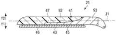
如图2和图3所示,第1钳构件21具有安装于轴5和杆25的钳构件主体部(第1钳构件主体部)41。在本实施方式中,钳构件主体部41仅由框构件42形成。框构件(支承构件)42从第1钳构件21的基端部至顶端部沿着第1钳构件轴线J1延伸设置。框构件42由包含不锈钢和钛中的至少一者的金属或包含聚醚醚酮(PEEK)和聚酰亚胺(PI)中的至少一者的耐热性树脂形成,框构件42的外表面由电绝缘材料形成。另外,第1钳构件21包括刀片(能量施加部)43和产生热量的发热部(发热体)45。刀片43和发热部45从第1钳构件21的基端部到顶端部沿着第1钳构件轴线J1延伸设置。刀片43由具有导电性、且导热性较高的材料(例如铜)形成。在第1钳构件21的外表面上设有与第2钳构件22相对的把持面(第1钳构件把持面)46和朝向与把持面46相反的侧(即,第1钳构件21的打开方向)的背面(第1钳构件背面)47。刀片43连结(固定)于框构件42(钳构件主体部41)的把持面侧(闭合方向侧),发热部45在第1钳构件21的开闭方向上设置在框构件42与刀片43之间。框构件(支承构件)42具有把持面侧端面(闭合方向侧端面)51和背面侧端面(打开方向侧端面)52。在本实施方式中,利用框构件42(钳构件主体部41)的背面侧端面(第1背面侧端面)52形成了第1钳构件21的背面47。另外,发热部45配置在框构件42的把持面侧端面(第2把持面侧端面)51与刀片43之间。而且,利用刀片43形成了第1钳构件21的把持面46。As shown in FIGS. 2 and 3 , thefirst jaw 21 has a jaw main body portion (first jaw main body portion) 41 attached to theshaft 5 and therod 25 . In the present embodiment, thejaw body portion 41 is formed only by theframe member 42 . The frame member (support member) 42 is extended along the first jaw axis J1 from the proximal end portion to the distal end portion of thefirst jaw 21 . Theframe member 42 is formed of a metal including at least one of stainless steel and titanium or a heat-resistant resin including at least one of polyetheretherketone (PEEK) and polyimide (PI), and the outer surface of theframe member 42 is Formed from an electrically insulating material. In addition, thefirst jaw 21 includes a blade (energy applying portion) 43 and a heat generating portion (heat generating body) 45 that generates heat. Theblade 43 and theheat generating portion 45 are extended along the first jaw axis J1 from the base end portion to the distal end portion of thefirst jaw 21 . Theblade 43 is formed of a material (eg, copper) having electrical conductivity and high thermal conductivity. On the outer surface of thefirst jaw 21 are provided a gripping surface (first jaw gripping surface) 46 facing thesecond jaw 22 , and a side facing the opposite side of the gripping surface 46 (ie, the opening of the first jaw 21 ). direction) of the back surface (the back surface of the first jaw) 47 . Theblade 43 is connected (fixed) to the grip surface side (closing direction side) of the frame member 42 (jaw main body portion 41 ), and theheat generating portion 45 is provided between theframe member 42 and theblade 43 in the opening and closing direction of thefirst jaw member 21 . between. The frame member (support member) 42 has a grip surface side end surface (closing direction side end surface) 51 and a back surface side end surface (opening direction side end surface) 52 . In this embodiment, theback surface 47 of thefirst jaw 21 is formed by the back surface side end surface (first back surface side end surface) 52 of the frame member 42 (jaw main body portion 41 ). Moreover, theheat generating part 45 is arrange|positioned between the grip surface side end surface (2nd grip surface side end surface) 51 of theframe member 42, and theblade 43. As shown in FIG. Furthermore, the grippingsurface 46 of thefirst jaw 21 is formed by theblade 43 .

在刀片(能量施加部)43的基端部连接有由电布线等形成的电力供给线(第1高频电力供给线)53的一端。电力供给线53经由轴5与杆25之间的空间、壳体主体部6的内部、线缆11的内部延伸设置,另一端连接于能量源单元10。从能量源单元10输出的高频电力经由电力供给线53向第1钳构件21的刀片43供给。通过向刀片43供给电力,从而刀片43作为电位与电极部32的电位不同的高频电力的电极(第1电极)发挥作用。刀片43将高频电力作为在处置中使用的能量从把持面46向处置对象施加。另外,由于框构件42的外表面由电绝缘材料形成,因此在框构件42中未供给(传递)有高频电力。One end of a power supply line (first high-frequency power supply line) 53 formed of an electric wiring or the like is connected to a proximal end portion of the blade (energy application portion) 43 . Thepower supply line 53 extends through the space between theshaft 5 and therod 25 , the inside of the casingmain body 6 , and the inside of thecable 11 , and the other end is connected to theenergy source unit 10 . The high-frequency power output from theenergy source unit 10 is supplied to theblade 43 of thefirst jaw 21 via thepower supply line 53 . By supplying electric power to theblade 43 , theblade 43 functions as an electrode (first electrode) of high-frequency power having a potential different from that of theelectrode portion 32 . Theblade 43 applies high-frequency power to the treatment target from thegrip surface 46 as energy used for treatment. In addition, since the outer surface of theframe member 42 is formed of an electrically insulating material, high-frequency power is not supplied (transmitted) to theframe member 42 .

在将第1钳构件21与第2钳构件22之间闭合的状态下,刀片43能够抵接于钳构件主体部(第2钳构件主体部)31的把持面侧端面(第2把持面侧端面)36。因而,在把持面侧端面36上形成第2钳构件22的把持面33的部位成为能够供刀片43抵接的抵接承受部55。通过在第1钳构件21与第2钳构件22之间没有处置对象的状态下将第1钳构件21与第2钳构件22之间闭合,从而刀片43抵接于抵接承受部55。在刀片43抵接于抵接承受部55的状态下,刀片43不与第2钳构件22的电极部32相接触,在刀片43与电极部32之间具有间隙。由此,防止了电位彼此不同的第2钳构件22的电极部32与第1钳构件21的刀片43之间的接触。In a state where the space between thefirst jaw 21 and thesecond jaw 22 is closed, theblade 43 can abut on the grip surface side end surface (second grip surface side) of the jaw body portion (second jaw body portion) 31 end face) 36. Therefore, the portion where thegrip surface 33 of thesecond jaw 22 is formed on the grip surfaceside end surface 36 becomes theabutment receiving portion 55 to which theblade 43 can abut. By closing the space between thefirst jaw 21 and thesecond jaw 22 in a state where there is no treatment object between thefirst jaw 21 and thesecond jaw 22 , theblade 43 comes into contact with theabutment receiving portion 55 . In a state where theblade 43 is in contact with theabutment receiving portion 55 , theblade 43 is not in contact with theelectrode portion 32 of thesecond jaw 22 , and there is a gap between theblade 43 and theelectrode portion 32 . Thereby, the contact between theelectrode part 32 of the2nd jaw 22 and theblade 43 of the1st jaw 21 which electric potential differs mutually is prevented.

在发热部45上连接有由电布线等形成的电力供给线(第1热电力供给线)57A和电力供给线(第2热电力供给线)57B的一端。电力供给线57A、57B经由轴5与杆25之间的空间、壳体主体部6的内部、线缆11的内部延伸设置,另一端连接于能量源单元10。能量源单元10除了上述高频电力以外,还能够输出向发热部45供给的热量产生电力(热量产生电能)。来自能量源单元10的热量产生电力经由电力供给线57A、57B向第1钳构件21的发热部45供给。通过向发热部45供给电力,从而产生热量。在发热部45中产生的热量经由刀片43向把持面(第1把持面)46传递,将热量作为在处置中使用的能量从把持面46施加于处置对象。One end of a power supply line (first thermal power supply line) 57A and a power supply line (second thermal power supply line) 57B formed of electrical wiring or the like are connected to theheat generating portion 45 . Thepower supply wires 57A and 57B extend through the space between theshaft 5 and therod 25 , the inside of the casingmain body 6 , and the inside of thecable 11 , and the other ends are connected to theenergy source unit 10 . Theenergy source unit 10 can output heat-generating power (heat-generating power) supplied to theheat generating part 45 in addition to the high-frequency power described above. The heat generating power from theenergy source unit 10 is supplied to theheat generating portion 45 of thefirst jaw 21 via thepower supply lines 57A and 57B. Heat is generated by supplying electric power to theheat generating portion 45 . The heat generated in theheat generating part 45 is transferred to the gripping surface (first gripping surface) 46 via theblade 43 , and the heat is applied from the grippingsurface 46 to the treatment object as energy used in the treatment.

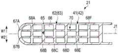
图4~图6是表示第1钳构件21的结构的图。图4表示第1钳构件21的与宽度方向垂直的截面,图5表示第1钳构件21的与第1钳构件轴线J1垂直的截面。另外,图6是图5的VI-VI线剖视图,表示第1钳构件21的与开闭方向垂直的截面。如图4~图6所示,框构件42具有板状的基座部61。利用基座部61形成了框构件42(钳构件主体部41)的把持面侧端面(闭合方向侧端面)51。另外,框构件42具有两端与基座部61连续的框部62。在本实施方式中,在与第1钳构件轴线J1垂直的截面上,框部62形成为大致半圆弧状。利用基座部61和框部62形成了框构件42的外框63。另外,框部62形成了框构件42的背面侧端面(打开方向侧端面)52。在本实施方式中,由于利用框构件42的背面侧端面52形成了第1钳构件21的背面47,因此利用框部62形成了第1钳构件21的背面47。另外,基座部61和框部62是框构件42的一部分,由包含不锈钢和钛中的至少一者的金属或包含聚醚醚酮(PEEK)和聚酰亚胺(PI)中的至少一者的耐热性树脂形成。4 to 6 are diagrams showing the configuration of thefirst jaw 21 . FIG. 4 shows a cross section perpendicular to the width direction of thefirst jaw 21 , and FIG. 5 shows a cross section perpendicular to the first jaw axis J1 of thefirst jaw 21 . 6 is a cross-sectional view taken along the line VI-VI of FIG. 5 , and shows a cross-section perpendicular to the opening and closing direction of thefirst jaw 21 . As shown in FIGS. 4 to 6 , theframe member 42 has a plate-shapedbase portion 61 . A grip surface side end surface (closing direction side end surface) 51 of the frame member 42 (jaw main body portion 41 ) is formed by thebase portion 61 . In addition, theframe member 42 has aframe portion 62 whose both ends are continuous with thebase portion 61 . In the present embodiment, theframe portion 62 is formed in a substantially semicircular arc shape in a cross section perpendicular to the first jaw axis J1. Theouter frame 63 of theframe member 42 is formed by thebase portion 61 and theframe portion 62 . In addition, theframe portion 62 forms the rear side end surface (the opening direction side end surface) 52 of theframe member 42 . In this embodiment, since theback surface 47 of thefirst jaw 21 is formed by the backside end surface 52 of theframe member 42 , theback surface 47 of thefirst jaw 21 is formed by theframe portion 62 . In addition, thebase portion 61 and theframe portion 62 are part of theframe member 42, and are made of metal including at least one of stainless steel and titanium, or at least one of polyetheretherketone (PEEK) and polyimide (PI). made of heat-resistant resin.

在外框63的内部,沿着第1钳构件21的开闭方向延伸设置有柱延伸设置部65。在外框63(框构件42)的内部,在未延伸设置有柱延伸设置部65的部分形成有空间66。因而,在外框63的内部,限定了以框构件42(外框63和柱延伸设置部65)为限定面的空间66。即,在基座部61与第1钳构件21的背面47之间,利用柱延伸设置部65限定了以框构件42为限定面的空间66。柱延伸设置部65的一端(把持面侧的端)与基座部61连续。另外,在本实施方式中,柱延伸设置部65的另一端(背面侧的端)与框部62连续。因此,在本实施方式中,柱延伸设置部65的两端与外框63连续。Inside theouter frame 63 , acolumn extending portion 65 is extended along the opening and closing direction of thefirst jaw 21 . Inside the outer frame 63 (frame member 42 ), aspace 66 is formed in a portion where thecolumn extending portion 65 is not extended. Therefore, inside theouter frame 63, aspace 66 is defined with the frame member 42 (theouter frame 63 and the column extending portion 65) as a defining surface. That is, between thebase portion 61 and theback surface 47 of thefirst jaw 21 , thespace 66 defined by theframe member 42 is defined by thecolumn extending portion 65 . One end (end on the grip surface side) of thecolumn extending portion 65 is continuous with thebase portion 61 . In addition, in the present embodiment, the other end (end on the back side) of thecolumn extension portion 65 is continuous with theframe portion 62 . Therefore, in the present embodiment, both ends of thecolumn extending portion 65 are continuous with theouter frame 63 .

柱延伸设置部65由沿着第1钳构件轴线J1延伸设置的轴向元件67A、67B和沿着第1钳构件21的宽度方向(在图5和图6中分别为箭头W1和箭头W2的方向)延伸设置的宽度方向元件68A~68F形成。因而,在本实施方式中,在第1钳构件21的与开闭方向(在图4和图5中分别为箭头Y1和箭头Y2的方向)垂直的截面上,利用柱延伸设置部65形成了格子结构70。Thecolumn extending portion 65 is composed ofaxial elements 67A, 67B extending along the first jaw axis J1 and along the width direction of the first jaw 21 (in FIGS. 5 and 6 , indicated by arrows W1 and W2, respectively).Width direction elements 68A to 68F extending in the direction) are formed. Therefore, in the present embodiment, in the cross-section perpendicular to the opening and closing directions of the first jaw 21 (directions of arrows Y1 and Y2 in FIGS. 4 and 5 , respectively), thecolumn extending portions 65 are formed to formLattice structure 70 .

接着,说明本实施方式的把持处置单元20和把持处置器具2的作用及效果。在使用把持处置系统1对生物体组织等处置对象进行处置时,将把持处置单元20(第1钳构件21和第2钳构件22)插入体内,将处置对象配置在第1钳构件21与第2钳构件22之间。然后,使可动手柄8相对于固定手柄7进行闭合动作,输入把持处置单元20的闭合操作。由此,第1钳构件21与第2钳构件22之间闭合,处置对象被把持在第1钳构件21与第2钳构件22之间。在把持着处置对象的状态下,利用能量操作输入部12输入能量操作。由此,从能量源单元10输出热量产生电力,并且输出高频电力。Next, the functions and effects of thegrasping treatment unit 20 and the grasping treatment tool 2 of the present embodiment will be described. When a treatment target such as a living tissue is treated using thegrasping treatment system 1, the grasping treatment unit 20 (thefirst jaw 21 and the second jaw 22) is inserted into the body, and the treatment target is placed between thefirst jaw 21 and thesecond jaw 22. 2 between thejaw members 22. Then, the movable handle 8 is closed with respect to the fixed handle 7 , and the closing operation of thegrasping treatment unit 20 is input. Thereby, the space between thefirst jaw 21 and thesecond jaw 22 is closed, and the treatment object is grasped between thefirst jaw 21 and thesecond jaw 22 . The energy operation is input by the energy operation input unit 12 while holding the treatment object. Thereby, heat is output from theenergy source unit 10 to generate electric power, and high-frequency electric power is output.

然后,通过从能量源单元10向发热部45供给热量产生电力,从而在发热部45中产生热量,产生的热量向形成于第1钳构件21的刀片43的把持面(第1把持面)46传递。由此,抵接于把持面46的处置对象被灼热,处置对象被切开。另外,若从能量源单元10向第2钳构件22的电极部32和第1钳构件21的刀片43供给高频电力,则电极部32和刀片43作为电位彼此不同的电极发挥作用。由此,高频电流经由把持在第1钳构件21与第2钳构件22之间的处置对象在电极部32与刀片43之间流动。利用高频电流,使处置对象改性,促进了凝固。Then, by supplying heat from theenergy source unit 10 to theheat generating portion 45 to generate electric power, heat is generated in theheat generating portion 45 , and the generated heat is directed to the gripping surface (first gripping surface) 46 of theblade 43 formed in thefirst jaw 21 . transfer. Thereby, the treatment object in contact with thegrip surface 46 is heated, and the treatment object is incised. When high-frequency power is supplied from theenergy source unit 10 to theelectrode portion 32 of thesecond jaw 22 and theblade 43 of thefirst jaw 21, theelectrode portion 32 and theblade 43 function as electrodes having different potentials from each other. Thereby, the high-frequency current flows between theelectrode portion 32 and theblade 43 via the treatment target held between thefirst jaw 21 and thesecond jaw 22 . Using high-frequency current, the treatment object is modified and coagulation is accelerated.

此时,在发热部45中产生的热量朝向把持面46侧传递,并且也朝向背面47侧传递。另外,通过将高频电力从把持面46施加于处置对象,从而在把持面46的附近产生热量。由此,由高频电力引起的热量朝向背面47侧传递。在本实施方式中,在钳构件主体部41的框构件42中,在外框63的内部限定了以框构件42为限定面的空间66。即,框构件42(钳构件主体部41)不是从把持面侧端面51到背面侧端面52在第1钳构件21的开闭方向上无间隙地连续,而是在把持面侧端面51与背面侧端面52之间形成有空间66作为空气层。因此,在框构件42的内部将热量的传递性保持得较低,在发热部45中产生的热量(在处置中使用的热量)和利用高频电力在把持面46的附近产生的热量(通过处置产生的热量)难以经由框构件42向背面47侧传递。因而,在把持面46的附近进行着处置的状态下,在第1钳构件21的外表面上,难以向除把持面46以外的部位传递热量。即,在第1钳构件21的外表面上,热量向除把持面46以外的部位传递的传递性被保持得较低。由此,能够减小在处置中使用的热量和通过处置产生的热量对除处置对象以外的生物体组织等的影响。At this time, the heat generated in theheat generating portion 45 is transmitted toward thegrip surface 46 side, and is also transmitted toward theback surface 47 side. In addition, heat is generated in the vicinity of the holdingsurface 46 by applying high-frequency power to the treatment object from the holdingsurface 46 . Thereby, the heat caused by the high-frequency power is transferred toward theback surface 47 side. In the present embodiment, in theframe member 42 of the jawmain body portion 41 , aspace 66 having theframe member 42 as a defining surface is defined inside theouter frame 63 . That is, the frame member 42 (jaw main body portion 41 ) is not continuous without a gap in the opening and closing direction of thefirst jaw 21 from theend surface 51 on the grip surface side to theend surface 52 on the back surface side, but is formed between theend surface 51 on the grip surface side and the back surface. Aspace 66 is formed between the side end surfaces 52 as an air layer. Therefore, the heat transfer property is kept low inside theframe member 42, and the heat generated in the heat generating part 45 (heat used for treatment) and the heat generated in the vicinity of thegrip surface 46 by high-frequency power (by The heat generated by the handling) is hardly transferred to theback surface 47 side via theframe member 42 . Therefore, in the state where the treatment is being performed in the vicinity of thegripping surface 46 , on the outer surface of thefirst jaw 21 , it is difficult to transfer heat to parts other than the grippingsurface 46 . That is, on the outer surface of thefirst jaw 21 , the transferability of heat to parts other than thegrip surface 46 is kept low. Thereby, it is possible to reduce the influence of the heat used in the treatment and the heat generated by the treatment on the living tissue and the like other than the treatment target.

另外,在本实施方式中,在框构件42中,在外框63的内部延伸设置有柱延伸设置部65,柱延伸设置部65的一端(把持面侧的端)与基座部61连续。因此,即使在外框63的内部形成有空间66,框构件42的刚性也不会降低,第1钳构件21的刚性也不会降低。由于将第1钳构件21的刚性保持得较高,因此即使在将处置对象保持在第1钳构件21与第2钳构件22之间、且对第1钳构件21施加有负荷的状态下,第1钳构件21也难以变形。由此,第1钳构件21与第2钳构件22之间的把持着处置对象的状态下的把持力量被保持得较大,能够确保处置性能。In the present embodiment, theframe member 42 is provided with thecolumn extension portion 65 extending inside theouter frame 63 , and one end (end on the grip surface side) of thecolumn extension portion 65 is continuous with thebase portion 61 . Therefore, even if thespace 66 is formed inside theouter frame 63, the rigidity of theframe member 42 does not decrease, and the rigidity of thefirst jaw 21 does not decrease. Since the rigidity of thefirst jaw 21 is kept high, even in a state where the object to be treated is held between thefirst jaw 21 and thesecond jaw 22 and a load is applied to thefirst jaw 21, Thefirst jaw 21 is also difficult to deform. Thereby, the holding force between thefirst jaw 21 and thesecond jaw 22 in a state where the treatment object is held is maintained large, and the treatment performance can be ensured.

另外,在本实施方式中,利用框部62和基座部61形成框构件42的外框63,柱延伸设置部65的另一端(背面侧的端)与框部62连续。因此,框构件42(钳构件主体部41)的刚性进一步提高,第1钳构件21的刚性进一步提高。而且,在本实施方式中,在第1钳构件21的与开闭方向垂直的截面上,利用柱延伸设置部65形成了格子结构70。因此,框构件42(钳构件主体部41)的刚性进一步提高,第1钳构件21的刚性提高。In addition, in the present embodiment, theouter frame 63 of theframe member 42 is formed by theframe portion 62 and thebase portion 61 , and the other end (end on the back side) of thecolumn extending portion 65 is continuous with theframe portion 62 . Therefore, the rigidity of the frame member 42 (jaw main body portion 41 ) is further improved, and the rigidity of thefirst jaw 21 is further improved. Furthermore, in the present embodiment, thelattice structure 70 is formed by thecolumn extending portion 65 in the cross-section perpendicular to the opening and closing direction of thefirst jaw 21 . Therefore, the rigidity of the frame member 42 (jaw main body portion 41 ) is further improved, and the rigidity of thefirst jaw 21 is improved.

如上所述,在本实施方式的把持处置单元20中,在第1钳构件21的外表面上将热量向除把持面46以外的部位传递的传递性保持得较低,并且也确保了第1钳构件21的刚性。另外,在向体内插入第1钳构件21的把持处置器具2中,需要使第1钳构件21小型化。在某一例子中,在与第1钳构件轴线J1垂直的截面处于直径5mm的圆的范围内的状态下,需要形成第1钳构件21。实际上,在将外框63的与第1钳构件轴线J1垂直的截面形状形成为矩形筒状的情况下,由于第1钳构件21大型化,因此与本实施方式同样地将外框63的与第1钳构件轴线J1垂直的截面形状形成为半圆筒状,以谋求第1钳构件21的小型化。但是,在将外框63的与第1钳构件轴线J1垂直的截面形状设为半圆筒状的情况下,在不设置柱延伸设置部65、且仅由外框63形成框构件42的无骨架式结构中,相对于在把持时施加的负荷(第1钳构件21的开闭方向上的力)的强度降低。因此,在本实施方式中,通过设置柱延伸设置部65,从而即使在将外框63的与第1钳构件轴线J1垂直的截面形状形成为半圆筒状的情况下,也确保了相对于在把持时施加的负荷的强度。As described above, in thegrasping treatment unit 20 of the present embodiment, the transferability of heat to the parts other than the graspingsurface 46 on the outer surface of thefirst jaw 21 is kept low, and the first Rigidity ofjaw 21 . In addition, in the grasping treatment tool 2 in which thefirst jaw 21 is inserted into the body, it is necessary to reduce the size of thefirst jaw 21 . In a certain example, it is necessary to form thefirst jaw 21 in a state where the cross section perpendicular to the first jaw axis J1 is within the range of a circle having a diameter of 5 mm. In fact, when the cross-sectional shape of theouter frame 63 perpendicular to the first jaw axis J1 is formed into a rectangular cylindrical shape, since the size of thefirst jaw 21 is increased, theouter frame 63 is changed in size as in the present embodiment. The cross-sectional shape perpendicular to the first jaw axis J1 is formed in a semi-cylindrical shape to reduce the size of thefirst jaw 21 . However, when the cross-sectional shape of theouter frame 63 perpendicular to the first jaw axis J1 is semi-cylindrical, thecolumn extending portion 65 is not provided, and only theouter frame 63 forms theframeless frame member 42 In the type structure, the strength with respect to the load (force in the opening and closing direction of the first jaw 21 ) applied at the time of grasping is reduced. Therefore, in the present embodiment, by providing thecolumn extending portion 65, even when the cross-sectional shape of theouter frame 63 perpendicular to the first jaw axis J1 is formed into a semi-cylindrical shape, it is ensured that the The strength of the load applied during the grip.

(第1实施方式的变形例)(Variation of the first embodiment)

另外,在第1实施方式中,在第1钳构件21的与开闭方向垂直的截面上,利用柱延伸设置部65形成了格子结构70,但是并不限于此。例如,作为第1实施方式的第1变形例如图7和图8所示,在第1钳构件21的与开闭方向垂直的截面上,也可以利用柱延伸设置部65形成蜂巢结构71。图7表示与第1钳构件21的第1钳构件轴线J1垂直的截面,图8表示图7的VIII-VIII线截面。在本变形例中,也是在框构件42的外框63的内部,在未延伸设置有柱延伸设置部65的部位形成有空间66。即,以框构件42为限定面的空间66被限定于外框63的内部。而且,柱延伸设置部65的一端(把持面侧的端)与基座部61连续,另一端(背面侧的端)与框部62连续。通过设为如上所述的结构,从而在本变形例中,也是在第1钳构件21的外表面上将热量向除把持面46以外的部位传递的传递性保持得较低,并且也确保了第1钳构件21的刚性。In addition, in the first embodiment, thelattice structure 70 is formed by thecolumn extending portion 65 in the cross-section perpendicular to the opening and closing direction of thefirst jaw 21, but the present invention is not limited to this. For example, as a first modification of the first embodiment, as shown in FIGS. 7 and 8 , thehoneycomb structure 71 may be formed by thecolumn extension 65 in the cross section perpendicular to the opening and closing direction of thefirst jaw 21 . FIG. 7 shows a cross section perpendicular to the first jaw axis J1 of thefirst jaw 21 , and FIG. 8 shows a cross section taken along the line VIII-VIII in FIG. 7 . Also in the present modification, aspace 66 is formed in the portion where thecolumn extending portion 65 is not extended inside theouter frame 63 of theframe member 42 . That is, thespace 66 defined by theframe member 42 is limited inside theouter frame 63 . Furthermore, one end (end on the grip surface side) of thecolumn extending portion 65 is continuous with thebase portion 61 , and the other end (end on the back side) is continuous with theframe portion 62 . By adopting the above-described configuration, also in this modification example, the transferability of heat to places other than the grippingsurface 46 is kept low on the outer surface of thefirst jaw 21, and the transferability is also ensured. Rigidity of thefirst jaw 21 .

另外,例如,作为第1实施方式的第2变形例如图9和图10所示,柱延伸设置部65也可以仅由沿着第1钳构件轴线J1延伸设置的轴向元件67A形成。图9表示第1钳构件21的与第1钳构件轴线J1垂直的截面,图10表示图9的X-X线截面。在本变形例中,也是在框构件42的外框63的内部,在未延伸设置有柱延伸设置部65的部位形成有空间66。即,以框构件42为限定面的空间66被限定于外框63的内部。而且,柱延伸设置部65的一端(把持面侧的端)与基座部61连续,另一端(背面侧的端)与框部62连续。通过设为如上所述的结构,从而在本变形例中,也是在第1钳构件21的外表面上将热量向除把持面46以外的部位传递的传递性保持得较低,并且也确保了第1钳构件21的刚性。In addition, for example, as a second modification of the first embodiment, as shown in FIGS. 9 and 10 , thecolumn extending portion 65 may be formed only by theaxial element 67A extending along the first jaw axis J1 . FIG. 9 shows a cross section of thefirst jaw 21 perpendicular to the first jaw axis J1 , and FIG. 10 shows a cross section taken along the line XX of FIG. 9 . Also in the present modification, aspace 66 is formed in the portion where thecolumn extending portion 65 is not extended inside theouter frame 63 of theframe member 42 . That is, thespace 66 defined by theframe member 42 is limited inside theouter frame 63 . Furthermore, one end (end on the grip surface side) of thecolumn extending portion 65 is continuous with thebase portion 61 , and the other end (end on the back side) is continuous with theframe portion 62 . By adopting the above-described configuration, also in this modification example, the transferability of heat to places other than the grippingsurface 46 is kept low on the outer surface of thefirst jaw 21, and the transferability is also ensured. Rigidity of thefirst jaw 21 .

另外,例如,作为第1实施方式的第3变形例如图11所示,柱延伸设置部65也可以仅一端(把持面侧的端)与基座部61连续,另一端(背面侧的端)不与框部62连续。图11表示第1钳构件21的与第1钳构件轴线J1垂直的截面。在本变形例中,在柱延伸设置部65的另一端与框部62之间形成有空间66。优选的是,柱延伸设置部65与图9和图10所示的轴向元件67A同样地沿着第1钳构件轴线J1延伸设置。在本变形例中,也是由于柱延伸设置部65的一端(把持面侧的端)与基座部61连续,因此确保了框构件42的刚性。因而,在本变形例中,也是在第1钳构件21的外表面上将热量向除把持面46以外的部位传递的传递性保持得较低,并且也确保了第1钳构件21的刚性。In addition, for example, as shown in FIG. 11 as a third modification of the first embodiment, only one end (end on the grip surface side) of thecolumn extending portion 65 may be continuous with thebase portion 61 and the other end (end on the back side) may be continuous with thebase portion 61 . Not continuous with theframe portion 62 . FIG. 11 shows a cross section of thefirst jaw 21 perpendicular to the first jaw axis J1. In this modification, aspace 66 is formed between the other end of thecolumn extending portion 65 and theframe portion 62 . It is preferable that thecolumn extending portion 65 is extended along the first jaw axis J1 like theaxial element 67A shown in FIGS. 9 and 10 . Also in this modification example, since one end (end on the grip surface side) of thecolumn extending portion 65 is continuous with thebase portion 61 , the rigidity of theframe member 42 is ensured. Therefore, also in this modification, the transferability of heat to the parts other than thegrip surface 46 is kept low on the outer surface of thefirst jaw 21 , and the rigidity of thefirst jaw 21 is also ensured.

另外,例如,在图12A所示的第1实施方式的第4变形例中,在框构件42的外框63的内部,在利用柱延伸设置部65形成的空间66(即,未延伸设置有柱延伸设置部65的部位)内填充有填充构件72。在本变形例中,利用框构件42和填充构件72形成了第1钳构件21的钳构件主体部(第1钳构件主体部)41。填充构件72由具有耐热性、且导热性比框构件42的导热性低的材料形成,例如,由包含钢、铝、不锈钢及钛中的至少一者的多孔质金属或包含聚醚醚酮(PEEK)和聚酰亚胺(PI)中的至少一者的发泡树脂形成。在本变形例中,也是柱延伸设置部65的一端(把持面侧的端)与基座部61连续。In addition, for example, in the fourth modification of the first embodiment shown in FIG. 12A , inside theouter frame 63 of theframe member 42 , thespace 66 formed by the column extending portion 65 (that is, not extending The fillingmember 72 is filled in the position of the column extending portion 65). In this modification, theframe member 42 and the fillingmember 72 form the jaw main body portion (first jaw main body portion) 41 of thefirst jaw 21 . The fillingmember 72 is formed of a material having heat resistance and thermal conductivity lower than that of theframe member 42 , for example, a porous metal containing at least one of steel, aluminum, stainless steel, and titanium, or a polyetheretherketone containing (PEEK) and a foamed resin of at least one of polyimide (PI). Also in this modification, one end (end on the grip surface side) of thecolumn extension portion 65 is continuous with thebase portion 61 .

在本变形例中,在框构件42中,在外框63的内部形成有空间66,在空间66内填充有填充构件72。即,框构件42不是从把持面侧端面51到背面侧端面52在第1钳构件21的开闭方向上无间隙地连续,而是在把持面侧端面51与背面侧端面52之间限定了以框构件42为限定面的空间66。而且,在利用框构件42形成的空间66内填充有填充构件72。向空间66内填充的填充构件72的导热性较低。因此,在本变形例中,也是在把持面46的附近进行处置的状态下,在第1钳构件21的外表面上,热量难以向除把持面46以外的部位传递。因而,在本变形例中,也是在第1钳构件21的外表面上将热量向除把持面46以外的部位的传递性保持得较低,并且也确保了第1钳构件21的刚性。In this modification, in theframe member 42 , aspace 66 is formed inside theouter frame 63 , and thespace 66 is filled with the fillingmember 72 . That is, theframe member 42 is not continuous from the grip surfaceside end surface 51 to the backside end surface 52 without a gap in the opening and closing direction of thefirst jaw 21 , but is defined between the grip surfaceside end surface 51 and the backside end surface 52 . Theframe member 42 serves as aspace 66 defining a surface. Further, thespace 66 formed by theframe member 42 is filled with a fillingmember 72 . The thermal conductivity of the fillingmember 72 filled into thespace 66 is low. Therefore, also in this modification, in the state where the treatment is performed in the vicinity of thegripping surface 46 , on the outer surface of thefirst jaw 21 , it is difficult for heat to be transferred to parts other than the grippingsurface 46 . Therefore, also in this modification example, the heat transfer property to the parts other than thegrip surface 46 is kept low on the outer surface of thefirst jaw 21 , and the rigidity of thefirst jaw 21 is also ensured.

另外,在本变形例中,在第1钳构件21的与开闭方向垂直的截面上,利用柱延伸设置部65形成了格子结构70,但是并不限于此。在填充构件72填充于空间66内的结构中,也可以与第1实施方式的第1变形例同样地在第1钳构件21的与开闭方向垂直的截面上,利用柱延伸设置部65形成有蜂巢结构71,还可以与第1实施方式的第2变形例同样地,柱延伸设置部65仅由轴向元件67A形成。另外,在填充构件72填充于空间66内的结构中,也可以与第1实施方式的第3变形例同样地使柱延伸设置部65的另一端(背面侧的端)不与框部62连续。In addition, in this modification, thelattice structure 70 is formed by thecolumn extending portion 65 in the cross-section perpendicular to the opening and closing direction of thefirst jaw 21, but the present invention is not limited to this. In the configuration in which the fillingmember 72 is filled in thespace 66 , thecolumn extending portion 65 may be formed in the cross section of thefirst jaw member 21 perpendicular to the opening and closing direction, as in the first modification of the first embodiment. With thehoneycomb structure 71, as in the second modification of the first embodiment, thecolumn extending portion 65 may be formed only by theaxial element 67A. In addition, in the configuration in which the fillingmember 72 is filled in thespace 66 , the other end (the end on the back side) of thecolumn extending portion 65 may not be continuous with theframe portion 62 as in the third modification of the first embodiment. .

另外,作为第1实施方式的第5变形例如图12B所示,且作为第1实施方式的第6变形例如图12C所示,也可以在框构件42的基座部61上设有孔69。孔69在第1钳构件21的开闭方向上贯穿基座部61。如第5变形例那样,也可以多个孔形成于基座部61,如第6变形例那样,也可以仅一个沿着第1钳构件轴线J1的长孔状的孔69形成于基座部61。通过设置孔69,从而来自发热部45的热量和通过处置而产生的热量难以经由把持面侧端面51向基座部61传递。由此,在第1钳构件21的外表面上能够将热量向除把持面46以外的部位传递的传递性保持得更低。In addition, as shown in FIG. 12B as a fifth modification of the first embodiment, and as shown in FIG. 12C as a sixth modification of the first embodiment, ahole 69 may be provided in thebase portion 61 of theframe member 42 . Thehole 69 penetrates thebase portion 61 in the opening and closing direction of thefirst jaw 21 . As in the fifth modification, a plurality of holes may be formed in thebase portion 61, and as in the sixth modification, only one long hole-shapedhole 69 along the first jaw axis J1 may be formed in thebase portion 61. By providing thehole 69 , the heat from theheat generating portion 45 and the heat generated by the treatment are less likely to be transferred to thebase portion 61 via the grip surfaceside end surface 51 . As a result, the transferability of heat to parts other than thegrip surface 46 can be kept lower on the outer surface of thefirst jaw 21 .

在第1实施方式及其变形例中,在第1钳构件(21)中,框构件(42)包括在框构件(42)上形成把持面侧端面(51)的板状的基座部(61)和两端与基座部(61)连续的框部(62)。基座部(61)和框部(62)协作形成框构件(42)的外框(63),在外框(63)的内部形成有以框构件(42)为限定面的空间(66)。柱延伸设置部(65)在外框(62)的内部延伸设置,一端与基座部(61)连续。In the first embodiment and its modification, in the first jaw member (21), the frame member (42) includes a plate-shaped base portion ( 61) and a frame portion (62) whose both ends are continuous with the base portion (61). The base part (61) and the frame part (62) cooperate to form an outer frame (63) of the frame member (42), and a space (66) with the frame member (42) as a limiting surface is formed inside the outer frame (63). The column extension part (65) is extended inside the outer frame (62), and one end is continuous with the base part (61).

(第2实施方式)(Second Embodiment)

接着,参照图13~图15说明本发明的第2实施方式。第2实施方式是将第1实施方式的结构如下所述变形后的实施方式。另外,对与第1实施方式相同的部分标注相同的附图标记,并省略其说明。Next, a second embodiment of the present invention will be described with reference to FIGS. 13 to 15 . The second embodiment is an embodiment in which the configuration of the first embodiment is modified as follows. In addition, the same code|symbol is attached|subjected to the same part as 1st Embodiment, and the description is abbreviate|omitted.

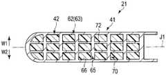
图13~图15是表示第1钳构件21的结构的图。图13表示第1钳构件21的与宽度方向垂直的截面,图14表示第1钳构件21的与第1钳构件轴线J1垂直的截面。另外,图15是图14的XV-XV线剖视图,表示第1钳构件21的与开闭方向垂直的截面。如图13~图15所示,在本实施方式中,也是框构件42具有板状的基座部61,利用基座部61形成了框构件42(钳构件主体部41)的把持面侧端面(闭合方向侧端面)51。但是,在本实施方式中,在框构件42上未设有框部62。13 to 15 are diagrams showing the configuration of thefirst jaw 21 . FIG. 13 shows a cross section perpendicular to the width direction of thefirst jaw 21 , and FIG. 14 shows a cross section perpendicular to the first jaw axis J1 of thefirst jaw 21 . In addition, FIG. 15 is a cross-sectional view taken along the line XV-XV in FIG. 14 , and shows a cross-section perpendicular to the opening and closing direction of thefirst jaw 21 . As shown in FIGS. 13 to 15 , also in this embodiment, theframe member 42 has a plate-shapedbase portion 61 , and thebase portion 61 forms the grip surface side end surface of the frame member 42 (jaw main body portion 41 ). (end surface on the side in the closing direction) 51 . However, in the present embodiment, theframe portion 62 is not provided on theframe member 42 .

在本实施方式中,也是在框构件42中沿着第1钳构件21的开闭方向延伸设置有柱延伸设置部65。柱延伸设置部65的一端(把持面侧的端)与基座部61连续。在本实施方式中,在第1钳构件21的与开闭方向(在图13和图14中分别为箭头Y1和箭头Y2的方向)垂直的截面上,利用柱延伸设置部65形成有格子结构70。Also in the present embodiment, theframe member 42 is provided with thecolumn extending portion 65 extending in the opening and closing direction of thefirst jaw 21 . One end (end on the grip surface side) of thecolumn extending portion 65 is continuous with thebase portion 61 . In the present embodiment, in the cross-section perpendicular to the opening and closing directions of the first jaw 21 (directions of arrows Y1 and Y2 in FIGS. 13 and 14 , respectively), a lattice structure is formed by thecolumn extending portions 65 . 70.

在本实施方式中,在比基座部61靠背面47侧的位置,在未延伸设置有柱延伸设置部65的部分形成有空间66。因而,在比基座部61靠背面47侧(第1钳构件21的打开方向侧)的位置,限定了以框构件42(基座部61和柱延伸设置部65)为限定面的空间66。即,在基座部61与第1钳构件21的背面47之间,利用柱延伸设置部65限定了以框构件42为限定面的空间66。In the present embodiment, aspace 66 is formed in a portion where thecolumn extending portion 65 is not extended at a position on theback surface 47 side relative to thebase portion 61 . Therefore, aspace 66 with the frame member 42 (thebase portion 61 and the column extension portion 65 ) as a limiting surface is defined at a position on theback surface 47 side (the opening direction side of the first jaw 21 ) from thebase portion 61 . . That is, between thebase portion 61 and theback surface 47 of thefirst jaw 21 , thespace 66 defined by theframe member 42 is defined by thecolumn extending portion 65 .

在本实施方式中,在利用柱延伸设置部65限定的空间66内填充有填充构件72。在本实施方式中,利用框构件42和填充构件72形成了钳构件主体部41。与第1实施方式的第4变形例同样地,填充构件72由具有耐热性、且导热性比框构件42的导热性低的材料形成,例如,由包含钢、铝、不锈钢及钛中的至少一者的多孔质金属或包含聚醚醚酮(PEEK)和聚酰亚胺(PI)中的至少一者的发泡树脂形成。在本实施方式中,基座部61和填充构件72协作形成了包围(覆盖)柱延伸设置部65的钳构件主体部41的外周表面73。另外,在本实施方式中,由于在框构件42上未设有框部62,因此利用填充构件72形成了第1钳构件21的背面47。In the present embodiment, thespace 66 defined by thecolumn extending portion 65 is filled with the fillingmember 72 . In the present embodiment, thejaw body portion 41 is formed by theframe member 42 and the fillingmember 72 . Like the fourth modification of the first embodiment, the fillingmember 72 is formed of a material having heat resistance and a thermal conductivity lower than that of theframe member 42 , for example, a material including steel, aluminum, stainless steel, and titanium. At least one of porous metal or foamed resin containing at least one of polyetheretherketone (PEEK) and polyimide (PI) is formed. In the present embodiment, thebase portion 61 and the fillingmember 72 cooperate to form the outerperipheral surface 73 of thejaw body portion 41 surrounding (covering) thecolumn extension portion 65 . In addition, in this embodiment, since theframe part 62 is not provided in theframe member 42, theback surface 47 of the1st jaw 21 is formed by thefiller member 72. As shown in FIG.

在本实施方式中,在框构件42中,在比基座部61靠背面侧的位置形成有空间66,在空间66内填充有填充构件72。因而,框构件42不是从把持面侧端面51到第1钳构件21的背面47在第1钳构件21的开闭方向上无间隙地连续,而是在把持面侧端面51与第1钳构件21的背面47之间限定有以框构件42为限定面的空间66。而且,在利用框构件42形成的空间66内填充有填充构件72。向空间66填充的填充构件72的导热性较低。因此,在本变形例中,也是在把持面46的附近进行了处置的状态下,在第1钳构件21的外表面上,热量难以向除把持面46以外的部位传递。In the present embodiment, in theframe member 42 , aspace 66 is formed on the back side of thebase portion 61 , and thespace 66 is filled with the fillingmember 72 . Therefore, theframe member 42 is not continuous without a gap in the opening and closing direction of thefirst jaw 21 from theend surface 51 on the grip surface side to theback surface 47 of thefirst jaw 21, but is formed between theend surface 51 on the grip surface side and thefirst jaw 21. Aspace 66 with theframe member 42 as a defining surface is defined between the back surfaces 47 of the 21 . Further, thespace 66 formed by theframe member 42 is filled with a fillingmember 72 . The thermal conductivity of the fillingmember 72 filling thespace 66 is low. Therefore, also in this modification, in the state where the treatment is performed in the vicinity of thegripping surface 46 , heat is less likely to be transferred to the portion other than the grippingsurface 46 on the outer surface of thefirst jaw 21 .

另外,在本实施方式中,也是在框构件42中,在比基座部61靠背面47侧的位置延伸设置有柱延伸设置部65,柱延伸设置部65的一端(把持面侧的端)与基座部61连续。因此,即使在比基座部61靠背面47侧的位置形成有空间66,框构件42的刚性也不会降低,第1钳构件21的刚性也不会降低。In the present embodiment, also in theframe member 42 , thecolumn extending portion 65 is extended at a position closer to theback surface 47 side than thebase portion 61 , and one end (the end on the grip surface side) of thecolumn extending portion 65 is provided. It is continuous with thebase portion 61 . Therefore, even if thespace 66 is formed at a position closer to theback surface 47 than thebase portion 61 , the rigidity of theframe member 42 does not decrease, and the rigidity of thefirst jaw 21 does not decrease.

因而,在本实施方式中,也是在第1钳构件21的外表面上将热量向除把持面46以外的部位传递的传递性保持得较低,并且也确保了第1钳构件21的刚性。Therefore, also in the present embodiment, the transferability of heat to parts other than thegrip surface 46 is kept low on the outer surface of thefirst jaw 21 , and the rigidity of thefirst jaw 21 is also ensured.

(第2实施方式的变形例)(Variation of the second embodiment)

另外,也可以与第1实施方式的第1变形例同样地在第1钳构件21的与开闭方向垂直的截面上,利用柱延伸设置部65形成有蜂巢结构71,还可以与第1实施方式的第2变形例同样地,柱延伸设置部65仅由轴向元件67A形成。In addition, like the first modification of the first embodiment, thehoneycomb structure 71 may be formed by thecolumn extending portion 65 in the cross section of thefirst jaw 21 perpendicular to the opening and closing direction, and the same as the first embodiment. Similarly to the second modification of the embodiment, thecolumn extending portion 65 is formed only by theaxial element 67A.

在第2实施方式及其变形例中,在第1钳构件(21)中,框构件(42)包括在框构件(42)上形成把持面侧端面(51)的板状的基座部(61)和一端与基座部(61)连续的柱延伸设置部(65)。比基座部(61)靠背面(47)侧的位置形成有以框构件(42)为限定面的空间(66),在空间(66)内填充有填充构件(72)。填充构件(72)由导热性比框构件(42)的导热性低的材料形成,并与框构件(42)协作形成包围柱延伸设置部(65)的外周表面(73)。In the second embodiment and its modification, in the first jaw member (21), the frame member (42) includes a plate-shaped base portion ( 61) and a column extension part (65) whose one end is continuous with the base part (61). A space (66) defined by the frame member (42) is formed on the back (47) side of the base (61), and the space (66) is filled with a filling member (72). The filling member (72) is formed of a material having lower thermal conductivity than that of the frame member (42), and cooperates with the frame member (42) to form an outer peripheral surface (73) surrounding the column extension (65).

(第1实施方式及第2实施方式的变形例)(Variations of the first embodiment and the second embodiment)

另外,在上述实施方式等中,具有限定空间66的框构件42的第1钳构件21能够相对于轴5转动,但是并不限于此。例如,作为第1实施方式及第2实施方式的第1变形例如图16所示,也可以是,第1钳构件21固定于轴5,第2钳构件22能够相对于轴5转动。在本变形例中也与第1实施方式及第2实施方式同样地,第2钳构件22包括钳构件主体部(支承构件)31和电极部(第2电极)32。In addition, in the said embodiment etc., although the1st jaw 21 which has theframe member 42 which defines thespace 66 is rotatable with respect to theshaft 5, it is not limited to this. For example, as shown in FIG. 16 as a first modification example of the first and second embodiments, thefirst jaw 21 may be fixed to theshaft 5 and thesecond jaw 22 may be rotatable with respect to theshaft 5 . Also in this modification, thesecond jaw 22 includes a jaw main body portion (support member) 31 and an electrode portion (second electrode) 32 as in the first and second embodiments.

另外,在本变形例中,在第1钳构件21上未设有刀片43和发热部45,取而代之设有电极部(第1电极部)75作为能量施加部。而且,利用电极部75形成了第1钳构件21的把持面46。电极部75能够抵接于第2钳构件22的钳构件主体部31,在电极部75与第1钳构件21相接触的状态下,第1钳构件21的电极部75与第2钳构件22的电极部(第2电极部)32不接触。在第1钳构件21的电极部75中供给有从能量源单元10输出的高频电力。通过向电极部75和电极部32供给高频电力,从而如在第1实施方式中所述那样,进行高频电流对处置对象的处置。即,在本变形例中,利用作为能量施加部的电极部75从把持面46向生物体组织施加高频电力(高频电流)作为在处置中使用的能量。Moreover, in this modification, theblade 43 and theheat generating part 45 are not provided in the1st jaw 21, and the electrode part (1st electrode part) 75 is provided as an energy application part instead. Furthermore, thegrip surface 46 of thefirst jaw 21 is formed by theelectrode portion 75 . Theelectrode portion 75 can be in contact with the jawmain body portion 31 of thesecond jaw 22 , and in a state where theelectrode portion 75 is in contact with thefirst jaw 21 , theelectrode portion 75 of thefirst jaw 21 and thesecond jaw 22 are in contact with each other. The electrode portion (second electrode portion) 32 of the 100 does not contact. The high-frequency power output from theenergy source unit 10 is supplied to theelectrode portion 75 of thefirst jaw 21 . By supplying the high-frequency power to theelectrode portion 75 and theelectrode portion 32, as described in the first embodiment, the treatment of the treatment target with the high-frequency current is performed. That is, in the present modification, high-frequency power (high-frequency current) is applied from the grippingsurface 46 to the living tissue as energy used for the treatment by theelectrode portion 75 serving as the energy applying portion.

在本变形例中,也是第1钳构件21的钳构件主体部41具有框构件42。而且,电极部(第1电极)75安装于框构件42的把持面侧端面51。在本变形例中,与第1实施方式同样地,框构件42包括基座部61、框部62以及柱延伸设置部65。因此,在框构件42的外框63的内部,利用柱延伸设置部65形成有空间66。Also in this modification, the jawmain body portion 41 of thefirst jaw 21 has theframe member 42 . Furthermore, the electrode portion (first electrode) 75 is attached to the grip surfaceside end surface 51 of theframe member 42 . In this modification, like the first embodiment, theframe member 42 includes abase portion 61 , aframe portion 62 , and acolumn extending portion 65 . Therefore, inside theouter frame 63 of theframe member 42 , aspace 66 is formed by thecolumn extending portion 65 .

另外,在某一变形例中,也可以是,电极部75设于第1钳构件21,并且钳构件主体部(第1钳构件主体部)41形成为与第1实施方式的变形例、第2实施方式及第2实施方式的变形例中任一者同样的结构。In addition, in a modification example, theelectrode portion 75 may be provided in thefirst jaw 21, and the jaw main body portion (first jaw main body portion) 41 may be formed in the same manner as in the modification example of the first embodiment, the first jaw main body portion Any one of the second embodiment and the modification of the second embodiment has the same configuration.

另外,作为第1实施方式及第2实施方式的第2变形例如图17所示,也可以是,在第1钳构件21的钳构件主体部(第1钳构件主体部)41设有框构件42,并且在第2钳构件22的钳构件主体部(第2钳构件主体部)31设有框构件81。在本变形例中,框架部(第1框构件)42形成为与第1实施方式同样的结构。In addition, as a second modification example of the first embodiment and the second embodiment, as shown in FIG. 17 , a frame member may be provided in the jaw main body portion (first jaw main body portion) 41 of thefirst jaw 21 . 42, and aframe member 81 is provided on the jaw main body portion (second jaw main body portion) 31 of thesecond jaw 22. In this modification, the frame part (1st frame member) 42 is formed in the same structure as 1st Embodiment.

框构件(第2框构件)81例如形成为与第1实施方式的框构件42同样的结构。即,框构件81包括基座部82和框部83,利用基座部82和框部83形成了外框85。而且,在外框85的内部延伸设置有柱延伸设置部86,柱延伸设置部86的一端(把持面侧的端)与基座部82连续。另外,在外框85的内部,利用柱延伸设置部86形成有以框构件81为限定面的空间87。由此,在本变形例中,在第2钳构件22的外表面上将热量向除把持面33以外的部位传递的传递性保持得较低,并且也确保了第2钳构件22的刚性。即,在第2钳构件22中,也起到与第1钳构件21同样的效果。The frame member (second frame member) 81 has, for example, the same structure as theframe member 42 of the first embodiment. That is, theframe member 81 includes thebase portion 82 and theframe portion 83 , and thebase portion 82 and theframe portion 83 form theouter frame 85 . Furthermore, acolumn extension portion 86 is extended inside theouter frame 85 , and one end (end on the grip surface side) of thecolumn extension portion 86 is continuous with thebase portion 82 . In addition, inside theouter frame 85 , aspace 87 with theframe member 81 as a limiting surface is formed by thecolumn extending portion 86 . Thereby, in this modification, the transferability of heat to parts other than thegrip surface 33 on the outer surface of thesecond jaw 22 is kept low, and the rigidity of thesecond jaw 22 is also ensured. That is, also in thesecond jaw 22, the same effect as that of thefirst jaw 21 is exhibited.

另外,在某一变形例中,第2钳构件22的框构件81也可以形成为与第1实施方式的变形例、第2实施方式及第2实施方式的变形例中的任一个框构件42同样的结构。In addition, in a certain modification, theframe member 81 of thesecond jaw 22 may be formed as any one of theframe members 42 of the modification of the first embodiment, the second embodiment, and the modification of the second embodiment. same structure.

另外,在上述实施方式等中,两个钳构件(21、22)的一者(例如第2钳构件22)固定于轴5,两个钳构件(21、22)的另一者(例如第1钳构件21)能够相对于轴5转动,但是并不限于此。在某一变形例中,第1钳构件21和第2钳构件22两者也可以以能够转动的方式安装于轴5。在该情况下,通过使杆25沿着长度轴线C移动,从而第1钳构件21和第2钳构件22两者相对于轴5转动。由此,在把持处置单元20中,第1钳构件21与第2钳构件22之间打开或闭合。In addition, in the above-described embodiment and the like, one of the two jaws (21, 22) (for example, the second jaw 22) is fixed to theshaft 5, and the other of the two jaws (21, 22) (for example, the second jaw 22) is fixed to theshaft 5. 1. The jaw member 21) can be rotated relative to theshaft 5, but is not limited to this. In a certain modification, both thefirst jaw 21 and thesecond jaw 22 may be rotatably attached to theshaft 5 . In this case, by moving therod 25 along the longitudinal axis C, both thefirst jaw 21 and thesecond jaw 22 are rotated relative to theshaft 5 . Thereby, in thegrasping treatment unit 20 , the space between thefirst jaw 21 and thesecond jaw 22 is opened or closed.

另外,作为第1实施方式及第2实施方式的第3变形例如图18所示,第1钳构件21也可以仅由钳构件主体部41(在本变形例中为框构件42)形成。在本变形例中,也是框构件42包括基座部61和柱延伸设置部65,限定有以框构件42为限定面的空间66。In addition, as a third modification of the first and second embodiments, as shown in FIG. 18 , thefirst jaw 21 may be formed of only the jaw main body 41 (in this modification, the frame member 42 ). Also in this modification, theframe member 42 includes thebase portion 61 and thecolumn extending portion 65, and defines aspace 66 with theframe member 42 as a limiting surface.

在本变形例中,框构件42的把持面侧端面51成为第1钳构件21的把持面46。即,利用框构件42的基座部61形成了把持面46。In this modification, the grip surfaceside end surface 51 of theframe member 42 becomes thegrip surface 46 of thefirst jaw 21 . That is, thegrip surface 46 is formed by thebase portion 61 of theframe member 42 .

在本变形例中,第2钳构件22仅由钳构件主体部(第2钳构件主体部)31形成。由于钳构件主体部31形成为从把持面侧端面36到背面侧端面37无间隙地连续的壁状(实心),因此第2钳构件22从把持面33到背面35无间隙地连续。在本变形例中,在保持单元3的内部设有超声波振子等振动产生部(未图示)。而且,能量源单元10具有将来自电源的电力转换为振动产生电力的转换电路,从能量源单元10输出的振动产生电力(振动产生电能)向振动产生部供给。由此,在振动产生部中产生超声波振动,超声波振动向第2钳构件22传递。In the present modification, thesecond jaw 22 is formed only by the jaw main body portion (second jaw main body portion) 31 . Since the jawmain body portion 31 is formed into a wall shape (solid) that is continuous from the grip surfaceside end surface 36 to the backside end surface 37 without a gap, thesecond jaw 22 is continuous from thegrip surface 33 to theback surface 35 without a gap. In this modification, a vibration generating portion (not shown) such as an ultrasonic vibrator is provided inside the holding unit 3 . Further, theenergy source unit 10 includes a conversion circuit that converts electric power from a power source into vibration-generating power, and the vibration-generating power (vibration-generating power) output from theenergy source unit 10 is supplied to the vibration generating unit. Thereby, ultrasonic vibration is generated in the vibration generating portion, and the ultrasonic vibration is transmitted to thesecond jaw 22 .

在第1钳构件21与第2钳构件22之间把持着处置对象的状态下,第2钳构件22通过超声波振动而振动,从而在凝固处置对象的同时切开处置对象。此时,在第1钳构件21的把持面46的附近,产生了热量。在本变形例中,也是由于与第1实施方式同样结构的框构件42设于第1钳构件21,因此在第1钳构件21的外表面上,热量难以向除把持面46以外的部位传递。另外,由于与第1实施方式同样结构的框构件42设于第1钳构件21,因此也确保了第1钳构件21的刚性。In a state where the treatment target is held between thefirst jaw 21 and thesecond jaw 22 , thesecond jaw 22 vibrates by ultrasonic vibration, thereby coagulating the treatment target and cutting the treatment target. At this time, heat is generated in the vicinity of thegrip surface 46 of thefirst jaw 21 . Also in this modification, since theframe member 42 having the same structure as that of the first embodiment is provided on thefirst jaw 21 , heat is less likely to be transferred to the portion other than thegrip surface 46 on the outer surface of thefirst jaw 21 . . In addition, since theframe member 42 having the same structure as that of the first embodiment is provided in thefirst jaw 21, the rigidity of thefirst jaw 21 is also ensured.

另外,在某一变形例中,也可以是,第1钳构件21仅由钳构件主体部41形成,并且钳构件主体部(第1钳构件主体部)41形成为与第1实施方式的变形例、第2实施方式及第2实施方式的变形例中的任一者同样的结构。In addition, in a certain modification example, thefirst jaw 21 may be formed only by the jawmain body portion 41, and the jaw main body portion (first jaw main body portion) 41 may be formed as a modification of the first embodiment. Example, the second embodiment, and any of the modified examples of the second embodiment have the same configuration.

只要为使用热量、高频、超声波振动等对把持在第1钳构件21与第2钳构件22之间的处置对象进行处置的把持处置单元20,就能够应用上述实施方式等的框构件42的结构。因而,在设于第1钳构件21的能量施加部(43;75)中,只要作为在处置中使用的能量的热量、高频以及超声波振动中的至少一种借助把持面46施加于处置对象即可。另外,在某一实施例中,也可以是,与热量、高频以及超声波振动不同的能量(例如微波、激光等)施加于处置对象。As long as it is thegrasping treatment unit 20 that treats the treatment object grasped between thefirst jaw 21 and thesecond jaw 22 using heat, high frequency, ultrasonic vibration, or the like, theframe member 42 of the above-described embodiment and the like can be applied. structure. Therefore, in the energy applying part ( 43 ; 75 ) provided in thefirst jaw 21 , as long as at least one of heat, high frequency, and ultrasonic vibration as energy used in the treatment is applied to the treatment object via the grippingsurface 46 That's it. In addition, in a certain embodiment, energy (eg, microwave, laser, etc.) different from heat, high frequency, and ultrasonic vibration may be applied to the treatment object.

在第1实施方式、第2实施方式及其变形例中,把持处置单元(20)包括从基端部朝向顶端部延伸设置的第1钳构件(21)和从基端部朝向顶端部延伸设置、且与第1钳构件(21)之间能够开闭的第2钳构件(22)。在第1钳构件(21)的外表面上设有与第2钳构件(22)相对的把持面(46)和朝向与把持面(46)相反的侧的背面(47)。在第1钳构件(21)上设有框构件(42),框构件(42)具有形成框构件(42)的把持面侧端面(51)的板状的基座部(61)。在框构件(42)中,从基座部(61)朝向背面(47)侧延伸设置有柱延伸设置部(65),柱延伸设置部(65)的一端与基座部(61)连续。在基座部(61)与第1钳构件(21)的背面(47)之间,利用柱延伸设置部(65)限定有以框构件(42)为限定面的空间(66)。In the first embodiment, the second embodiment, and the modification thereof, the grasping treatment unit (20) includes a first jaw member (21) extending from the proximal end portion toward the distal end portion, and extending from the proximal end portion toward the distal end portion and a second jaw (22) which can be opened and closed with the first jaw (21). A grip surface (46) facing the second jaw (22) and a back surface (47) facing the opposite side to the grip surface (46) are provided on the outer surface of the first jaw (21). A frame member (42) is provided on the first jaw member (21), and the frame member (42) has a plate-shaped base portion (61) forming a grip surface side end surface (51) of the frame member (42). In the frame member (42), a column extending portion (65) extends from the base portion (61) toward the back surface (47) side, and one end of the column extending portion (65) is continuous with the base portion (61). Between the base portion (61) and the back surface (47) of the first jaw member (21), a space (66) with the frame member (42) as a limiting surface is defined by the column extending portion (65).

(第3实施方式)(third embodiment)

接着,参照图19说明本发明的第3实施方式。第3实施方式是将第1实施方式的结构如下所述变形后的实施方式。另外,对与第1实施方式相同的部分标注相同的附图标记,并省略其说明。Next, a third embodiment of the present invention will be described with reference to FIG. 19 . The third embodiment is an embodiment in which the configuration of the first embodiment is modified as follows. In addition, the same code|symbol is attached|subjected to the same part as 1st Embodiment, and the description is abbreviate|omitted.

图19是利用与宽度方向垂直的截面表示第1钳构件21的图。在本实施方式中也与第1实施方式同样地,第1钳构件21的钳构件主体部(第1钳构件主体部)41具有框构件42。而且,在框构件42上设有基座部61和柱延伸设置部65,在基座部61与第1钳构件21的背面47之间,利用柱延伸设置部65限定有以框构件42为限定面的空间66。另外,在本实施方式中,与第1实施方式同样地设有框部62。而且,在基座部61和框部62的内部延伸设置有柱延伸设置部65,在基座部61和框部62的内部形成有空间66。另外,在第1钳构件21的与开闭方向垂直的截面上,利用柱延伸设置部65形成了格子结构70。FIG. 19 is a diagram showing thefirst jaw 21 with a cross section perpendicular to the width direction. Also in this embodiment, similarly to the first embodiment, the jaw main body portion (first jaw main body portion) 41 of thefirst jaw 21 has aframe member 42 . Further, theframe member 42 is provided with abase portion 61 and acolumn extension portion 65, and between thebase portion 61 and theback surface 47 of thefirst jaw member 21, thecolumn extension portion 65 defines aframe member 42 as aSpace 66 that defines the face. In addition, in this embodiment, theframe part 62 is provided similarly to 1st Embodiment. Further, acolumn extending portion 65 is extended inside thebase portion 61 and theframe portion 62 , and aspace 66 is formed inside thebase portion 61 and theframe portion 62 . In addition, in the cross section perpendicular to the opening and closing direction of thefirst jaw 21 , thelattice structure 70 is formed by thecolumn extending portion 65 .

但是,在本实施方式中,基座部61、框部62以及柱延伸设置部65在钳构件主体部41(框构件42)中仅设于顶端侧的部位。例如,基座部61、框部62以及柱延伸设置部65仅设置在第1钳构件21的长度方向(第1钳构件长度方向)上的比中间位置靠顶端侧的部位。因而,利用柱延伸设置部65限定的空间66在框构件42(钳构件主体部41)中仅形成于顶端侧的部位。在框构件42的顶端侧的部位,利用基座部61形成了框构件42的把持面侧端面51,利用框部62形成了框构件42的背面侧端面52(在本实施方式中为第1钳构件21的背面47)。However, in the present embodiment, thebase portion 61 , theframe portion 62 , and thecolumn extending portion 65 are provided only at the distal end side of the jaw main body portion 41 (frame member 42 ). For example, thebase portion 61 , theframe portion 62 , and thecolumn extending portion 65 are provided only on the distal end side of the intermediate position in the longitudinal direction (first jaw longitudinal direction) of thefirst jaw 21 . Therefore, thespace 66 defined by thecolumn extension portion 65 is formed only in the portion on the distal end side of the frame member 42 (jaw main body portion 41 ). At the portion on the distal end side of theframe member 42, thebase portion 61 forms the grip surface side end face 51 of theframe member 42, and theframe portion 62 forms the rear side end face 52 of the frame member 42 (in this embodiment, the first end face 52).Backside 47 of jaw 21).

另外,在本实施方式中,在框构件42(钳构件主体部41)的基端侧的部位设有壁部91。例如,壁部91仅设置在第1钳构件21的长度方向(第1钳构件长度方向)上的比中间位置靠基端侧的部位。因而,壁部91在框构件42中位于比基座部61、框部62以及柱延伸设置部65靠基端侧的位置。在壁部91中,框构件42从把持面侧端面51到背面侧端面52无间隙地连续。因而,在框构件42的基端侧的部位,利用壁部91形成了把持面侧端面51和背面侧端面52。Moreover, in this embodiment, thewall part 91 is provided in the site|part on the proximal end side of the frame member 42 (jaw main body part 41). For example, thewall portion 91 is provided only on the proximal end side of the intermediate position in the longitudinal direction of the first jaw 21 (the first jaw longitudinal direction). Therefore, thewall portion 91 is located on the proximal end side of theframe member 42 rather than thebase portion 61 , theframe portion 62 , and thecolumn extending portion 65 . In thewall portion 91, theframe member 42 is continuous from theend surface 51 on the grip surface side to theend surface 52 on the back surface side without a gap. Therefore, the grip surfaceside end surface 51 and the back surfaceside end surface 52 are formed by thewall portion 91 at the proximal end side portion of theframe member 42 .

由于如上所述形成了框构件42,因此在本实施方式的框构件42中,仅在顶端侧的部位形成有空间。因此,在钳构件主体部41中,热量在顶端侧的部位的传导性比热量在基端侧的部位的传导性低。而且,在钳构件主体部41中,在基端侧的部位的刚性比在顶端侧的部位的刚性高。Since theframe member 42 is formed as described above, in theframe member 42 of the present embodiment, a space is formed only in the portion on the distal end side. Therefore, in the jawmain body portion 41 , the heat conductivity of the portion on the distal end side is lower than the heat conductivity of the portion on the proximal end side. Furthermore, in the jawmain body portion 41 , the rigidity of the portion on the proximal end side is higher than that of the portion on the distal end side.

在使用热量、高频等能量进行处置时,在第1钳构件21的背面47上,顶端侧的部位与除处置对象以外的生物体组织等接触的可能性升高。在本实施方式中,在框构件42的顶端侧的部位,热量的传导性降低。因此,在第1钳构件21的顶端侧的部位,热量难以向除把持面46以外的外表面传递。通过在第1钳构件21的顶端部中将热量向除把持面46以外的外表面传递的传递性保持得较低,从而能够可靠地减小热量对除处置对象以外的生物体组织的影响。When the treatment is performed using energy such as heat and high frequency, therear surface 47 of thefirst jaw 21 is more likely to come into contact with a body tissue other than the treatment target at the distal end side. In the present embodiment, the thermal conductivity is lowered at the portion on the distal end side of theframe member 42 . Therefore, in the portion on the distal end side of thefirst jaw 21 , it is difficult for heat to be transferred to the outer surface other than thegrip surface 46 . In the distal end portion of thefirst jaw 21 , the transferability of heat to the outer surfaces other than thegrip surface 46 is kept low, so that the influence of the heat on living tissues other than the treatment target can be reliably reduced.

另外,在第1钳构件21与第2钳构件22之间把持着处置对象时,在第1钳构件21中,在基端侧的部位施加有较大的负荷。在本实施方式中,由于框构件42的在基端侧的部位的刚性提高,因此在第1钳构件21中,在基端侧的部位的刚性也提高。由此,第1钳构件21更加难以变形,能够可靠地将第1钳构件21与第2钳构件22之间的把持着处置对象的状态下的把持力量保持得较大。因而,能够提高对把持在第1钳构件21与第2钳构件22之间的处置对象进行处置时的处置性能。In addition, when the treatment object is gripped between thefirst jaw 21 and thesecond jaw 22 , a large load is applied to the proximal end side of thefirst jaw 21 . In the present embodiment, since the rigidity of the portion on the proximal end side of theframe member 42 is improved, the rigidity of the portion on the proximal end side of thefirst jaw 21 is also improved. Thereby, thefirst jaw 21 is more difficult to deform, and the gripping force between thefirst jaw 21 and thesecond jaw 22 in a state where the treatment object is gripped can be kept large reliably. Therefore, the treatment performance at the time of treatment of the treatment object held between thefirst jaw 21 and thesecond jaw 22 can be improved.

(第3实施方式的变形例)(Variation of the third embodiment)

另外,在框构件42的基端侧的部位设有壁部91的结构中,也可以与第1实施方式的第1变形例同样地在第1钳构件21的与开闭方向垂直的截面上,利用柱延伸设置部65形成了蜂巢结构71,还可以与第1实施方式的第2变形例同样地,柱延伸设置部65仅由轴向元件67A形成。另外,也可以与第1实施方式的第3变形例同样地,柱延伸设置部65的另一端(背面侧的端)不与框部62连续,还可以与第1实施方式的第4变形例同样地在空间66内填充有填充构件72。另外,在框构件42的基端侧的部位设有壁部91的结构中,也可以与第2实施方式及其变形例同样地在框构件42上不设有框部62,在比基座部61靠背面侧的位置利用填充构件72填充了空间66。另外,在像第1实施方式及第2实施方式的变形例所示的各个变形例那样形成有把持处置单元20的结构中,也可以使用与第3实施方式同样地在框构件42的基端侧的部位设有壁部91的第1钳构件21。另外,向处置对象施加的能量也可以是热量、高频以及超声波振动中的至少一种,还可以是与热量、高频电力及超声波振动不同的能量(例如微波、激光等)施加于处置对象。In addition, even in the configuration in which thewall portion 91 is provided at the base end side of theframe member 42, the cross section of thefirst jaw 21 perpendicular to the opening and closing direction may be similar to the first modification of the first embodiment. Although thehoneycomb structure 71 is formed by thecolumn extending portion 65, thecolumn extending portion 65 may be formed only by theaxial element 67A, as in the second modification of the first embodiment. In addition, as in the third modification of the first embodiment, the other end (end on the back side) of thecolumn extending portion 65 may not be continuous with theframe portion 62, and the fourth modification of the first embodiment may be used. Similarly, thespace 66 is filled with a fillingmember 72 . In addition, even in the configuration in which thewall portion 91 is provided at the base end side of theframe member 42, theframe member 42 may not be provided with theframe portion 62 as in the second embodiment and its modification, and theframe member 42 may not be provided in the base The position on the back side of theportion 61 is filled with thespace 66 by the fillingmember 72 . In addition, in the configuration in which thegrasping treatment unit 20 is formed like the modification examples shown in the first embodiment and the modification examples of the second embodiment, the base end of theframe member 42 may be used in the same manner as in the third embodiment. Thefirst jaw 21 of thewall portion 91 is provided at the side portion. In addition, the energy applied to the treatment object may be at least one of heat, high frequency, and ultrasonic vibration, or energy (eg, microwave, laser, etc.) different from heat, high-frequency power, and ultrasonic vibration may be applied to the treatment object. .

在第3实施方式及其变形例中,把持处置单元(20)包括从基端部朝向顶端部延伸设置的第1钳构件(21)和从基端部朝向顶端部延伸设置、且与第1钳构件(21)之间能够开闭的第2钳构件(22)。在第1钳构件(21)的外表面上设有与第2钳构件(22)相对的把持面(46)和朝向与把持面(46)相反的侧的背面(47)。在第1钳构件(21)上设有具有框构件(42)的钳构件主体部(41),框构件(42)具有在框构件(42)的顶端侧的部位形成把持面侧端面(51)的板状的基座部(61)。在框构件(42)的顶端侧的部位,从基座部(61)朝向背面(47)侧延伸设置有柱延伸设置部(65),柱延伸设置部(65)的一端与基座部(61)连续。另外,在钳构件主体部(41)的顶端侧的部位,在基座部(61)与第1钳构件(21)的背面(47)之间,利用柱延伸设置部(65)限定有以框构件(42)为限定面的空间(66)。而且,在框构件(42)中,在比基座部(61)和柱延伸设置部(65)靠基端侧的位置设有壁部(91),在壁部(91)中,框构件(42)从把持面侧端面(51)到背面侧端面(52)无间隙地连续。In the third embodiment and its modification, the grasping treatment unit (20) includes a first jaw member (21) extending from the proximal end toward the distal end, and extending from the proximal end toward the distal portion, and is connected to the first jaw member (21) extending from the proximal end toward the distal end A second jaw (22) which can be opened and closed between the jaws (21). A grip surface (46) facing the second jaw (22) and a back surface (47) facing the opposite side to the grip surface (46) are provided on the outer surface of the first jaw (21). The first jaw (21) is provided with a jaw main body (41) having a frame member (42) having an end surface (51) on the distal end side of the frame member (42) that forms a gripping surface ) of the plate-shaped base portion (61). At the front end side of the frame member (42), a column extending portion (65) is extended from the base portion (61) toward the back (47) side, and one end of the column extending portion (65) is connected to the base portion ( 61) Continuous. In addition, at the distal end side of the jaw body portion (41), between the base portion (61) and the back surface (47) of the first jaw (21), a post extending portion (65) defines a The frame member (42) is a space (66) defining a face. Furthermore, in the frame member (42), a wall portion (91) is provided at a position closer to the base end side than the base portion (61) and the column extending portion (65), and in the wall portion (91), the frame member (42) It is continuous from the grip surface side end surface (51) to the back surface side end surface (52) without a gap.

由于是如上所述的结构,因此在第3实施方式及其变形例中,在第1钳构件(21)的钳构件主体部(41)中,热量在顶端侧的部位的传导性比热量在基端侧的部位的传导性低,在基端侧的部位的刚性比在顶端侧的部位的刚性高。Because of the above-described configuration, in the third embodiment and its modification, in the jaw body portion (41) of the first jaw (21), the heat conductivity of the portion on the distal end side is higher than that of the heat The conductivity of the portion on the proximal side is low, and the rigidity of the portion on the proximal side is higher than that of the portion on the distal side.

(第4实施方式)(fourth embodiment)

接着,参照图20说明本发明的第4实施方式。第4实施方式是将第3实施方式的结构如下所述变形后的实施方式。另外,对与第3实施方式同样的部分标注同样的附图标记,并省略其说明。Next, a fourth embodiment of the present invention will be described with reference to FIG. 20 . The fourth embodiment is an embodiment in which the configuration of the third embodiment is modified as follows. In addition, the same code|symbol is attached|subjected to the same part as 3rd Embodiment, and the description is abbreviate|omitted.

在第3实施方式中,在设于框构件42的壁部91中,框构件42从把持面侧端面51到背面侧端面52无间隙地连续,但是在本实施方式中,取代壁部91,壁部95在框构件42上设置在比基座部61和柱延伸设置部65靠基端侧的位置。在本实施方式中,在壁部95中,在框构件42的把持面侧端面51与背面侧端面52之间形成有一个空洞96。空洞96被壁部95包围。因而,在本实施方式中,在壁部95中是框构件42与把持面侧端面51和背面侧端面52无间隙地连续的结构。In the third embodiment, in thewall portion 91 provided in theframe member 42, theframe member 42 is continuous from the grip surfaceside end surface 51 to the backside end surface 52 without a gap, but in this embodiment, instead of thewall portion 91, Thewall portion 95 is provided on the base end side of theframe member 42 rather than thebase portion 61 and thecolumn extending portion 65 . In the present embodiment, onecavity 96 is formed in thewall portion 95 between theend surface 51 on the grip surface side and theend surface 52 on the back surface side of theframe member 42 . Thecavity 96 is surrounded by thewall portion 95 . Therefore, in the present embodiment, thewall portion 95 has a structure in which theframe member 42 is continuous with the grip surfaceside end surface 51 and the back surfaceside end surface 52 without a gap.

但是,在本实施方式中,也是在框构件42(钳构件主体部)41中,壁部95设置在比基座部61和柱延伸设置部65靠基端侧的位置。而且,在框构件42(钳构件主体部)41中,壁部95的刚性比设有基座部61和柱延伸设置部65的框构件42的在顶端侧的部位的刚性高。即,形成于壁部95的空洞96的体积较小。因此,在本实施方式中也与第3实施方式同样地,在第1钳构件21中,也是在基端侧的部位的刚性提高。由此,在本实施方式中,也是第1钳构件21更加难以变形,可靠地将第1钳构件21与第2钳构件22之间的把持着处置对象的状态下的把持力量保持得较大。However, also in the present embodiment, in the frame member 42 (jaw main body portion) 41 , thewall portion 95 is provided on the proximal end side of thebase portion 61 and thecolumn extension portion 65 . Furthermore, in the frame member 42 (jaw main body portion) 41 , the rigidity of thewall portion 95 is higher than that of the portion on the distal end side of theframe member 42 in which thebase portion 61 and thecolumn extension portion 65 are provided. That is, the volume of thecavity 96 formed in thewall portion 95 is small. Therefore, also in this embodiment, similarly to the third embodiment, in thefirst jaw 21, the rigidity of the site on the proximal end side is improved. As a result, also in the present embodiment, thefirst jaw 21 is more difficult to deform, and the gripping force between thefirst jaw 21 and thesecond jaw 22 in the state where the treatment object is gripped can be kept large reliably .

(第4实施方式的变形例)(Variation of the fourth embodiment)

另外,在第4实施方式中,在壁部95上仅形成有一个空洞96,但是在某一变形例中,在壁部95上,也可以在把持面侧端面51与背面侧端面52之间形成有多个空洞(96)。但是,在该情况下,空洞(96)的体积的合计也较小,壁部95的刚性比设有基座部61和柱延伸设置部65的框构件42的在顶端侧的部位的刚性高。因而,与第4实施方式同样地在第1钳构件21中,在基端侧的部位的刚性提高。In addition, in the fourth embodiment, only onecavity 96 is formed in thewall portion 95 , but in a modification example, thewall portion 95 may be located between theend surface 51 on the grip surface side and theend surface 52 on the back surface side A plurality of voids (96) are formed. However, in this case, the total volume of the cavity ( 96 ) is also small, and the rigidity of thewall portion 95 is higher than that of the portion on the distal end side of theframe member 42 in which thebase portion 61 and thecolumn extension portion 65 are provided. . Therefore, in thefirst jaw 21, as in the fourth embodiment, the rigidity of the site on the proximal end side is improved.

(第5实施方式)(Fifth Embodiment)

接着,参照图21说明本发明的第5实施方式。第5实施方式是将第3实施方式的结构如下所述变形后的实施方式。另外,对与第3实施方式同样的部分标注同样的附图标记,并省略其说明。Next, a fifth embodiment of the present invention will be described with reference to FIG. 21 . The fifth embodiment is an embodiment in which the configuration of the third embodiment is modified as follows. In addition, the same code|symbol is attached|subjected to the same part as 3rd Embodiment, and the description is abbreviate|omitted.

图21是利用与宽度方向垂直的截面表示第1钳构件21的图。如图21所示,在本实施方式中,在钳构件主体部41上未设有框构件42。取而代之,在本实施方式中,钳构件主体部41由第1材料部92和第2材料部93形成。第1材料部92由包含聚醚醚酮和聚酰亚胺的至少一者的树脂等的第1材料形成,第2材料部93由导热性比第1材料的导热性高、且刚性比第1材料的刚性高的第2材料形成,例如由包含不锈钢和钛中的至少一者的金属形成。另外,在本实施方式中,第1钳构件21的背面47利用钳构件主体部41形成。FIG. 21 is a diagram showing thefirst jaw 21 with a cross section perpendicular to the width direction. As shown in FIG. 21 , in the present embodiment, theframe member 42 is not provided on the jawmain body portion 41 . Instead, in the present embodiment, the jawmain body portion 41 is formed of thefirst material portion 92 and thesecond material portion 93 . Thefirst material portion 92 is formed of a first material such as a resin containing at least one of polyether ether ketone and polyimide, and thesecond material portion 93 is made of a thermal conductivity higher than that of the first material and rigidity higher than that of the first material. The second material having high rigidity of the first material is formed of, for example, a metal including at least one of stainless steel and titanium. In addition, in the present embodiment, theback surface 47 of thefirst jaw 21 is formed by the jawmain body portion 41 .

在钳构件主体部41中,在顶端侧的部位,与基端侧的部位相比,第1材料部92相对于第2材料部93所占的比例较大。因此,钳构件主体部41的顶端侧的部位与钳构件主体部41的基端侧的部位相比,第1材料的含有率提高。因而,在第1钳构件21的钳构件主体部41中,热量在顶端侧的部位的传导性比热量在基端侧的部位的传导性低,在基端侧的部位的刚性比在顶端侧的部位的刚性高。In the jawmain body portion 41 , the ratio of thefirst material portion 92 to thesecond material portion 93 is larger in the portion on the distal end side than in the portion on the proximal end side. Therefore, the content rate of the first material is higher in the portion on the distal end side of the jawmain body portion 41 than in the portion on the proximal end side of the jawmain body portion 41 . Therefore, in the jawmain body portion 41 of thefirst jaw 21, the heat conductivity of the portion on the distal side is lower than that of the portion on the proximal side, and the rigidity of the portion on the proximal side is lower than that on the distal side. The rigidity of the part is high.

在本实施方式中也与第3实施方式同样地在钳构件主体部(第1钳构件主体部)41的顶端侧的部位,热量的传导性降低。因此,在第1钳构件21的顶端侧的部位,热量难以向除把持面46以外的外表面传递。另外,在本实施方式中也与第3实施方式同样地在钳构件主体部41的基端侧的部位,刚性提高,因此在第1钳构件21中也是,在基端侧的部位的刚性提高。由此,第1钳构件21更加难以变形,可靠地将第1钳构件21与第2钳构件22之间的把持着处置对象的状态下的把持力量保持得较大。Also in the present embodiment, similarly to the third embodiment, the heat conductivity is lowered in the region on the distal end side of the jaw main body portion (first jaw main body portion) 41 . Therefore, in the portion on the distal end side of thefirst jaw 21 , it is difficult for heat to be transferred to the outer surface other than thegrip surface 46 . In addition, in the present embodiment, as in the third embodiment, the rigidity of the proximal end side portion of the jawmain body portion 41 is improved, and therefore the rigidity of the proximal end side portion of thefirst jaw 21 is also improved. . Thereby, thefirst jaw 21 is more difficult to deform, and the gripping force between thefirst jaw 21 and thesecond jaw 22 in a state where the treatment object is gripped is kept large reliably.

(第5实施方式的变形例)(Variation of the fifth embodiment)

另外,在像第1实施方式及第2实施方式的变形例所示的各个变形例那样形成有把持处置单元20的结构中,也可以与第5实施方式同样地使用钳构件主体部41由第1材料部92和第2材料部93形成的第1钳构件21。另外,向处置对象施加的能量也可以是热量、高频以及超声波振动中的至少一种,也可以是与热量、高频以及超声波振动不同的能量(例如微波、激光等)施加于处置对象。In addition, in the configuration in which thegrasping treatment unit 20 is formed as in each of the modifications shown in the first embodiment and the second embodiment, the jawmain body 41 can be used as in the fifth embodiment to remove the Thefirst jaw 21 formed by thefirst material portion 92 and thesecond material portion 93 . In addition, the energy applied to the treatment object may be at least one of heat, high frequency, and ultrasonic vibration, or energy (eg, microwave, laser, etc.) different from heat, high frequency, and ultrasonic vibration may be applied to the treatment object.

在第5实施方式及其变形例中,钳构件主体部(41)由第1材料和导热性比第1材料的导热性高、且刚性比第1材料的刚性高的第2材料形成。钳构件主体部(41)的顶端侧的部位与钳构件主体部(41)的基端侧的部位相比,第1材料的含有率升高。因此,在第4实施方式及其变形例中,在第1钳构件(21)的钳构件主体部(41)中,热量在顶端侧的部位的传导性比热量在基端侧的部位的传导性低,在基端侧的部位的刚性比在顶端侧的部位的刚性高。In the fifth embodiment and its modification, the jaw main body (41) is formed of the first material and the second material having higher thermal conductivity than the first material and higher rigidity than the first material. The portion on the distal end side of the jaw main body portion (41) has a higher content rate of the first material than the portion on the proximal end side of the jaw main body portion (41). Therefore, in the fourth embodiment and its modification, in the jaw body portion (41) of the first jaw (21), the heat conductivity at the distal side portion is higher than the heat conduction at the proximal end side portion The rigidity of the site on the proximal side is higher than the rigidity of the site on the distal side.

以上,说明了本发明的实施方式等,但是本发明并不限定于上述实施方式等,当然在不脱离本发明的主旨的范围内能够进行各种变形。The embodiments and the like of the present invention have been described above, but the present invention is not limited to the above-mentioned embodiments and the like, and it goes without saying that various modifications can be made without departing from the gist of the present invention.

以下,附记特征事项。Hereinafter, the characteristic matters are appended.

remember

(附记项1)(Additional item 1)

一种把持处置单元,其中,该把持处置单元包括:A holding treatment unit, wherein the holding treatment unit includes:

第1钳构件,其从基端部朝向顶端部延伸设置;a first jaw member extending from the base end portion toward the tip end portion;

第2钳构件,其从基端部朝向顶端部延伸设置,且该第2钳构件与所述第1钳构件之间能够开闭;a second jaw member extending from the base end portion toward the distal end portion, and the second jaw member and the first jaw member can be opened and closed;

把持面,其在所述第1钳构件的外表面上与所述第2钳构件相对;a gripping surface opposite to the second jaw member on the outer surface of the first jaw member;

背面,其在所述第1钳构件的所述外表面上朝向与所述把持面相反侧的方向;以及a back face that faces a direction opposite to the gripping surface on the outer surface of the first jaw; and

钳构件主体部,其设于所述第1钳构件,并且热量在顶端侧的部位的传导性比热量在基端侧的部位的传导性低,所述在基端侧的部位的刚性比所述在顶端侧的部位的刚性高。The jaw main body is provided in the first jaw, and the heat conductivity of the portion on the distal end side is lower than that of the portion on the proximal end side, and the rigidity of the portion on the proximal end side is lower than that of the The rigidity of the portion on the distal end side is high.

(附记项2)(Additional item 2)

根据附记项1的把持处置单元,其中,The grasping and handling unit according tosupplementary item 1, wherein,

所述钳构件主体部具有框构件,The jaw member main body has a frame member,

所述框构件包括:The frame member includes:

板状的基座部,其在所述钳构件主体部的所述顶端侧的部位形成所述框构件的把持面侧端面;a plate-shaped base portion that forms an end face on the grip surface side of the frame member at a portion on the distal end side of the jaw body portion;

柱延伸设置部,其在所述钳构件主体部的所述顶端侧的部位从所述基座部朝向背面侧延伸设置,并且一端与所述基座部连续,在所述钳构件主体部的所述顶端侧的部位且在所述基座部与所述第1钳构件的所述背面之间限定以所述框构件为限定面的空间;以及A post extending portion extending from the base portion toward the back side at the distal end side portion of the jaw body portion, one end being continuous with the base portion, a space on the distal end side and a space defined by the frame member between the base portion and the back surface of the first jaw member; and

壁部,其设置在比所述基座部和所述柱延伸设置部靠基端侧的位置,在该壁部中所述框构件从所述把持面侧端面到所述框构件的背面侧端面无间隙地连续。a wall portion provided at a position on the proximal end side of the base portion and the column extending portion, in which the frame member extends from the grip surface side end surface to the back side of the frame member The end faces are continuous without gaps.

(附记项3)(Additional item 3)

根据附记项2的把持处置单元,其中,The grasping and handling unit according to Supplementary Note 2, wherein,

所述钳构件主体部具有框部,该框部在所述钳构件主体部的所述顶端侧的部位形成所述框构件的所述背面侧端面,并且与所述基座部协作形成所述钳构件主体部的外框,在所述外框的内部延伸设置有柱延伸设置部。The jaw body portion has a frame portion that forms the rear side end surface of the frame member at a portion on the distal end side of the jaw body portion, and that cooperates with the base portion to form the The outer frame of the jaw body portion has a column extending portion extending inside the outer frame.

(附记项4)(Additional item 4)

根据附记项1的把持处置单元,其中,The grasping and handling unit according tosupplementary item 1, wherein,

所述钳构件主体部由第1材料和导热性比所述第1材料的导热性高、且刚性比所述第1材料的刚性高的第2材料形成,The jaw body portion is formed of a first material and a second material having higher thermal conductivity than the first material and higher rigidity than the first material,

所述钳构件主体部的所述顶端侧的部位与所述钳构件主体部的所述基端侧的部位相比,所述第1材料的含有率升高。The content of the first material is higher in the portion on the distal end side of the jaw main body portion than in the portion on the proximal end side of the jaw main body portion.

(附记项5)(Additional item 5)

根据附记项4的把持处置单元,其中,The grasping and handling unit according to Supplementary Note 4, wherein,

所述第1材料是含有聚醚醚酮和聚酰亚胺中的至少一者的树脂,The first material is a resin containing at least one of polyether ether ketone and polyimide,

所述第2材料是含有不锈钢和钛中的至少一者的金属。The second material is a metal containing at least one of stainless steel and titanium.

Claims (12)

Translated fromChinese
1.一种把持处置单元,其中,该把持处置单元包括:1. A holding treatment unit, wherein the holding treatment unit comprises:第1钳构件,其从基端部朝向顶端部延伸设置,在所述第1钳构件中具有框构件;a first jaw member extending from a proximal end portion toward a distal end portion, and having a frame member in the first jaw member;第2钳构件,其从基端部朝向顶端部延伸设置,且该第2钳构件与所述第1钳构件之间能够开闭;a second jaw member extending from the base end portion toward the distal end portion, and the second jaw member and the first jaw member can be opened and closed;能量施加部,其连结于所述框构件,在将所述第1钳构件和所述第2钳构件闭合的状态下,能够抵接于所述第2钳构件,并将在处置中使用的能量施加给处置对象;An energy application part connected to the frame member, capable of abutting on the second jaw member in a state in which the first jaw member and the second jaw member are closed, and applying the energy is applied to the object of treatment;板状的基座部,其在所述框构件上形成朝向第2钳构件侧的所述框构件的端面;以及a plate-shaped base portion formed on the frame member with an end face of the frame member facing the second jaw member side; and柱延伸设置部,其一端与所述基座部连续,该柱延伸设置部在所述第1钳构件的所述框构件上从所述基座部朝向所述第1钳构件的背面延伸设置,所述柱延伸设置部通过在朝向所述第1钳构件的打开方向侧的所述第1钳构件的背面与所述基座部之间形成空间,在将所述能量施加部产生的热量向所述背面传递的传递性保持得较低的同时,保持所述第1钳构件的刚性;A column extending portion whose one end is continuous with the base portion, the column extending portion extending from the base portion toward the back surface of the first jaw member on the frame member of the first jaw member The column extending portion forms a space between the back surface of the first jaw member toward the opening direction side of the first jaw member and the base portion, so that the heat generated by the energy applying portion is applied The rigidity of the first jaw member is maintained while the transferability to the back surface is kept low;所述第1钳构件与第2钳构件分体设置。The first jaw member and the second jaw member are provided separately.2.根据权利要求1所述的把持处置单元,其中,2. The grasping treatment unit according to claim 1, wherein:所述柱延伸设置部的另一端与所述框构件连续。The other end of the column extending portion is continuous with the frame member.3.根据权利要求2所述的把持处置单元,其中,3. The holding treatment unit according to claim 2, wherein:所述第1钳构件具有填充构件,该填充构件向在所述框构件的内部的所述空间中未延伸设置有所述柱延伸设置部的部位填充,该填充构件由导热性比所述框构件的导热性低的材料形成。The first jaw member has a filling member that fills the space inside the frame member where the column extending portion is not extended, and the filling member has a higher thermal conductivity than the frame. The member is formed of a material with low thermal conductivity.4.根据权利要求3所述的把持处置单元,其中,4. The grip treatment unit according to claim 3, wherein:所述填充构件由包含钢、铝及钛中的至少一者的多孔质金属或包含聚醚醚酮和聚酰亚胺中的至少一者的发泡树脂形成。The filling member is formed of a porous metal including at least one of steel, aluminum, and titanium, or a foamed resin including at least one of polyetheretherketone and polyimide.5.根据权利要求1所述的把持处置单元,其中,5. The grasping treatment unit according to claim 1, wherein:所述柱延伸设置部在所述第1钳构件的与开闭方向垂直的截面上形成格子结构和蜂巢结构中的至少一种结构。The column extending portion forms at least one of a lattice structure and a honeycomb structure in a cross section of the first jaw member perpendicular to the opening and closing direction.6.根据权利要求1所述的把持处置单元,其中,6. The grip treatment unit according to claim 1, wherein:所述框构件由含有不锈钢和钛中的至少一者的金属或含有聚醚醚酮和聚酰亚胺中的至少一者的耐热性树脂形成。The frame member is formed of a metal containing at least one of stainless steel and titanium, or a heat-resistant resin containing at least one of polyetheretherketone and polyimide.7.根据权利要求1所述的把持处置单元,其中,7. The grip treatment unit according to claim 1, wherein:在所述基座部上形成有在所述第1钳构件的开闭方向上贯穿所述基座部的孔。A hole that penetrates the base portion in the opening and closing direction of the first jaw is formed in the base portion.8.根据权利要求1所述的把持处置单元,其中,8. The grasping treatment unit according to claim 1, wherein:所述能量施加部形成所述第1钳构件的与所述第2钳构件相对的把持面,并从所述把持面施加在处置中使用的能量。The energy application unit forms a gripping surface of the first jaw that faces the second jaw, and applies energy used for treatment from the gripping surface.9.根据权利要求8所述的把持处置单元,其中,9. The grip treatment unit according to claim 8, wherein:所述能量施加部经由所述把持面施加的在所述处置中使用的所述能量为热量、高频以及超声波振动中的至少一种。The energy used for the treatment, which is applied by the energy application unit via the grip surface, is at least one of heat, high frequency, and ultrasonic vibration.10.根据权利要求1所述的把持处置单元,其中,10. The grip treatment unit according to claim 1, wherein:所述基座部和所述柱延伸设置部在所述第1钳构件中设于顶端侧的部位,The base portion and the column extending portion are provided at a portion of the first jaw member on the distal end side,所述框构件具有壁部,该壁部设置在比所述基座部和所述柱延伸设置部靠基端侧的位置,在该壁部中所述框构件从所述端面到所述框构件的背面侧的端部无间隙地连续。The frame member has a wall portion provided at a position closer to the base end side than the base portion and the column extending portion, and the frame member extends from the end surface to the frame in the wall portion. The end on the back side of the member is continuous without a gap.11.根据权利要求1所述的把持处置单元,其中,11. The grip treatment unit according to claim 1, wherein:所述基座部和所述柱延伸设置部在所述第1钳构件中设于顶端侧的部位,The base portion and the column extending portion are provided at a portion of the first jaw member on the distal end side,所述框构件具有壁部,该壁部设置在比所述基座部和所述柱延伸设置部靠基端侧的位置,该壁部的刚性比设有所述基座部和所述柱延伸设置部的所述顶端侧的部位的刚性高,The frame member has a wall portion provided at a position closer to the base end side than the base portion and the column extending portion, and the wall portion is more rigid than the base portion and the column provided with the wall portion. The portion on the distal end side of the extending portion has high rigidity,所述壁部在所述端面与所述框构件的背面侧的端部之间具有被所述壁部包围的至少一个空洞。The wall portion has at least one cavity surrounded by the wall portion between the end surface and the end portion on the rear side of the frame member.12.一种把持处置器具,其中,该把持处置器具包括:12. A holding and treatment device, wherein the holding and treatment device comprises:权利要求1的把持处置单元;The handling unit of claim 1;保持单元,其能够用于保持,该保持单元设置在比所述把持处置单元靠基端侧的位置;以及a holding unit that can be used for holding, the holding unit being provided at a position closer to the proximal end side than the holding treatment unit; and开闭操作输入部,其设于所述保持单元,该开闭操作输入部用于输入将所述把持处置单元的所述第1钳构件与所述第2钳构件之间打开或闭合的开闭操作。An opening/closing operation input unit provided in the holding unit, the opening/closing operation input unit for inputting an opening/closing operation for opening or closing between the first jaw member and the second jaw member of the grasping treatment unit close operation.
CN201580052484.7A2014-12-242015-11-27Holding treatment unit and holding treatment toolActiveCN106794042B (en)

Applications Claiming Priority (3)

Application NumberPriority DateFiling DateTitle
JP2014-2604642014-12-24
JP20142604642014-12-24
PCT/JP2015/083419WO2016104051A1 (en)2014-12-242015-11-27Grasping treatment unit and grasping treatment tool

Publications (2)

Publication NumberPublication Date
CN106794042A CN106794042A (en)2017-05-31
CN106794042Btrue CN106794042B (en)2020-08-14

Family

ID=56150083

Family Applications (1)

Application NumberTitlePriority DateFiling Date
CN201580052484.7AActiveCN106794042B (en)2014-12-242015-11-27Holding treatment unit and holding treatment tool

Country Status (5)

CountryLink
US (1)US20170224405A1 (en)
EP (1)EP3205303A4 (en)
JP (1)JP6076574B2 (en)
CN (1)CN106794042B (en)
WO (1)WO2016104051A1 (en)

Families Citing this family (28)

* Cited by examiner, † Cited by third party
Publication numberPriority datePublication dateAssigneeTitle
US11090104B2 (en)2009-10-092021-08-17Cilag Gmbh InternationalSurgical generator for ultrasonic and electrosurgical devices
US9408622B2 (en)2012-06-292016-08-09Ethicon Endo-Surgery, LlcSurgical instruments with articulating shafts
US10194973B2 (en)2015-09-302019-02-05Ethicon LlcGenerator for digitally generating electrical signal waveforms for electrosurgical and ultrasonic surgical instruments
US11129670B2 (en)2016-01-152021-09-28Cilag Gmbh InternationalModular battery powered handheld surgical instrument with selective application of energy based on button displacement, intensity, or local tissue characterization
US11229471B2 (en)2016-01-152022-01-25Cilag Gmbh InternationalModular battery powered handheld surgical instrument with selective application of energy based on tissue characterization
US12193698B2 (en)2016-01-152025-01-14Cilag Gmbh InternationalMethod for self-diagnosing operation of a control switch in a surgical instrument system
US11051840B2 (en)2016-01-152021-07-06Ethicon LlcModular battery powered handheld surgical instrument with reusable asymmetric handle housing
US11266430B2 (en)2016-11-292022-03-08Cilag Gmbh InternationalEnd effector control and calibration
US12082808B2 (en)2019-12-302024-09-10Cilag Gmbh InternationalSurgical instrument comprising a control system responsive to software configurations
US12076006B2 (en)2019-12-302024-09-03Cilag Gmbh InternationalSurgical instrument comprising an orientation detection system
US12262937B2 (en)2019-12-302025-04-01Cilag Gmbh InternationalUser interface for surgical instrument with combination energy modality end-effector
BR112022012554A2 (en)2019-12-302022-10-04Cilag Gmbh Int ELECTROSURGICAL END ACTUATORS WITH THERMALLY CONDUCTIVE AND THERMALLY INSULATING PORTIONS
US11944366B2 (en)2019-12-302024-04-02Cilag Gmbh InternationalAsymmetric segmented ultrasonic support pad for cooperative engagement with a movable RF electrode
US11786294B2 (en)2019-12-302023-10-17Cilag Gmbh InternationalControl program for modular combination energy device
US12336747B2 (en)2019-12-302025-06-24Cilag Gmbh InternationalMethod of operating a combination ultrasonic / bipolar RF surgical device with a combination energy modality end-effector
US11812957B2 (en)2019-12-302023-11-14Cilag Gmbh InternationalSurgical instrument comprising a signal interference resolution system
US20210196357A1 (en)*2019-12-302021-07-01Ethicon LlcElectrosurgical instrument with asynchronous energizing electrodes
US11937866B2 (en)2019-12-302024-03-26Cilag Gmbh InternationalMethod for an electrosurgical procedure
US11950797B2 (en)2019-12-302024-04-09Cilag Gmbh InternationalDeflectable electrode with higher distal bias relative to proximal bias
US11786291B2 (en)2019-12-302023-10-17Cilag Gmbh InternationalDeflectable support of RF energy electrode with respect to opposing ultrasonic blade
US12023086B2 (en)2019-12-302024-07-02Cilag Gmbh InternationalElectrosurgical instrument for delivering blended energy modalities to tissue
US12343063B2 (en)2019-12-302025-07-01Cilag Gmbh InternationalMulti-layer clamp arm pad for enhanced versatility and performance of a surgical device
CN114901186A (en)*2019-12-302022-08-12西拉格国际有限公司 Electrosurgical instrument with electrode bias support
US11779387B2 (en)2019-12-302023-10-10Cilag Gmbh InternationalClamp arm jaw to minimize tissue sticking and improve tissue control
US12053224B2 (en)2019-12-302024-08-06Cilag Gmbh InternationalVariation in electrode parameters and deflectable electrode to modify energy density and tissue interaction
US11937863B2 (en)2019-12-302024-03-26Cilag Gmbh InternationalDeflectable electrode with variable compression bias along the length of the deflectable electrode
US11986201B2 (en)2019-12-302024-05-21Cilag Gmbh InternationalMethod for operating a surgical instrument
US11844562B2 (en)2020-03-232023-12-19Covidien LpElectrosurgical forceps for grasping, treating, and/or dividing tissue

Family Cites Families (13)

* Cited by examiner, † Cited by third party
Publication numberPriority datePublication dateAssigneeTitle
EA200600951A1 (en)*2003-11-102007-10-26Серджинетикс, Инк. ELECTRO SURGICAL TOOL
JP2005348820A (en)*2004-06-082005-12-22Olympus CorpHeating element, medical treatment tool and apparatus using thereof
US20070016210A1 (en)*2005-07-132007-01-18Boehm Frank H JrDevice and method for use to create multiple bone grafts for use in fusion
US20090299353A1 (en)*2008-04-112009-12-03Lumenis Ltd.Tissue Treatment Device and Method
DE102010022431A1 (en)*2010-06-012011-12-01Karl Storz Gmbh & Co. Kg Medical gripping tool
US8979890B2 (en)*2010-10-012015-03-17Ethicon Endo-Surgery, Inc.Surgical instrument with jaw member
JP5622551B2 (en)*2010-12-142014-11-12オリンパス株式会社 THERAPEUTIC TREATMENT DEVICE AND ITS CONTROL METHOD
JP2012239831A (en)*2011-05-242012-12-10Olympus CorpTherapeutic treatment apparatus
US8968317B2 (en)*2011-08-182015-03-03Covidien LpSurgical forceps
US9592093B2 (en)*2011-09-062017-03-14University of Pittsburgh—of the Commonwealth System of Higher EducationTactile feedback system for robotic surgery
JP5931604B2 (en)*2012-06-282016-06-08オリンパス株式会社 Therapeutic treatment device
WO2016006379A1 (en)*2014-07-102016-01-14オリンパス株式会社Energy treatment unit and energy treatment tool
US10206705B2 (en)*2014-11-252019-02-19Ethicon LlcFeatures for communication of fluid through shaft assembly of ultrasonic surgical instrument

Also Published As

Publication numberPublication date
CN106794042A (en)2017-05-31
JPWO2016104051A1 (en)2017-04-27
JP6076574B2 (en)2017-02-08
WO2016104051A1 (en)2016-06-30
EP3205303A1 (en)2017-08-16
US20170224405A1 (en)2017-08-10
EP3205303A4 (en)2018-05-30

Similar Documents

PublicationPublication DateTitle
CN106794042B (en)Holding treatment unit and holding treatment tool
JP5836543B1 (en) Ultrasonic probe and ultrasonic treatment apparatus
US11596464B2 (en)Medical apparatus
JP5797353B2 (en) Grasping treatment device and grasping unit
CN106999228B (en)Holding treatment unit
JP5977908B2 (en) Grasping treatment unit, grasping treatment instrument, and grasping treatment system
CN103717160A (en)Gripping and treating device
US10070913B2 (en)Grasping treatment unit, grasping treatment instrument and grasping treatment system
CN110573101A (en) Plasma irradiation device, handpiece, and surgical device
EP3189804B1 (en)Surgical clamping unit, surgical clamping tool, and surgical clamping system
US10010342B2 (en)Ultrasonic probe and ultrasonic treatment apparatus
CN110234283B (en)Treatment tool
US20190110831A1 (en)Treatment tool
WO2018055778A1 (en)Treatment instrument and treatment system
WO2016047241A1 (en)Vibration-generating unit, vibration component unit, and ultrasonic wave processing implement
WO2018087841A1 (en)Vibration transmitting member and ultrasonic treatment tool
CN109922749B (en)Medical device
CN108697451B (en)Treatment tool
WO2018198339A1 (en)Energy treatment tool and treatment system
WO2018092278A1 (en)Energy treatment tool
US20180055555A1 (en)Therapeutic energy applying structure and medical treatment device
WO2018146729A1 (en)Energy applying structure and treatment tool
JP2005185656A (en)Surgical treatment instrument
US20180344380A1 (en)Energy treatment tool
WO2018131126A1 (en)Heat treatment tool

Legal Events

DateCodeTitleDescription
PB01Publication
PB01Publication
SE01Entry into force of request for substantive examination
GR01Patent grant
GR01Patent grant

[8]ページ先頭

©2009-2025 Movatter.jp