CN106691580B - System and method for ultrasound image guided ablation antenna placement - Google Patents
System and method for ultrasound image guided ablation antenna placementDownload PDFInfo
- Publication number
- CN106691580B CN106691580BCN201611027154.5ACN201611027154ACN106691580BCN 106691580 BCN106691580 BCN 106691580BCN 201611027154 ACN201611027154 ACN 201611027154ACN 106691580 BCN106691580 BCN 106691580B
- Authority
- CN
- China
- Prior art keywords
- ablation
- ultrasound image
- ablation probe
- computing device
- user interface
- Prior art date
- Legal status (The legal status is an assumption and is not a legal conclusion. Google has not performed a legal analysis and makes no representation as to the accuracy of the status listed.)
- Active
Links
Images


Classifications
- A—HUMAN NECESSITIES
- A61—MEDICAL OR VETERINARY SCIENCE; HYGIENE
- A61B—DIAGNOSIS; SURGERY; IDENTIFICATION
- A61B18/00—Surgical instruments, devices or methods for transferring non-mechanical forms of energy to or from the body
- A61B18/18—Surgical instruments, devices or methods for transferring non-mechanical forms of energy to or from the body by applying electromagnetic radiation, e.g. microwaves
- A61B18/1815—Surgical instruments, devices or methods for transferring non-mechanical forms of energy to or from the body by applying electromagnetic radiation, e.g. microwaves using microwaves
- A—HUMAN NECESSITIES
- A61—MEDICAL OR VETERINARY SCIENCE; HYGIENE
- A61B—DIAGNOSIS; SURGERY; IDENTIFICATION
- A61B18/00—Surgical instruments, devices or methods for transferring non-mechanical forms of energy to or from the body
- A61B18/04—Surgical instruments, devices or methods for transferring non-mechanical forms of energy to or from the body by heating
- A61B18/12—Surgical instruments, devices or methods for transferring non-mechanical forms of energy to or from the body by heating by passing a current through the tissue to be heated, e.g. high-frequency current
- A61B18/14—Probes or electrodes therefor
- A—HUMAN NECESSITIES
- A61—MEDICAL OR VETERINARY SCIENCE; HYGIENE
- A61B—DIAGNOSIS; SURGERY; IDENTIFICATION
- A61B34/00—Computer-aided surgery; Manipulators or robots specially adapted for use in surgery
- A61B34/10—Computer-aided planning, simulation or modelling of surgical operations
- A—HUMAN NECESSITIES
- A61—MEDICAL OR VETERINARY SCIENCE; HYGIENE
- A61B—DIAGNOSIS; SURGERY; IDENTIFICATION
- A61B34/00—Computer-aided surgery; Manipulators or robots specially adapted for use in surgery
- A61B34/20—Surgical navigation systems; Devices for tracking or guiding surgical instruments, e.g. for frameless stereotaxis
- A—HUMAN NECESSITIES
- A61—MEDICAL OR VETERINARY SCIENCE; HYGIENE
- A61B—DIAGNOSIS; SURGERY; IDENTIFICATION
- A61B34/00—Computer-aided surgery; Manipulators or robots specially adapted for use in surgery
- A61B34/25—User interfaces for surgical systems
- A—HUMAN NECESSITIES
- A61—MEDICAL OR VETERINARY SCIENCE; HYGIENE
- A61B—DIAGNOSIS; SURGERY; IDENTIFICATION
- A61B8/00—Diagnosis using ultrasonic, sonic or infrasonic waves
- A61B8/08—Clinical applications
- A61B8/0833—Clinical applications involving detecting or locating foreign bodies or organic structures
- A61B8/0841—Clinical applications involving detecting or locating foreign bodies or organic structures for locating instruments
- A—HUMAN NECESSITIES
- A61—MEDICAL OR VETERINARY SCIENCE; HYGIENE
- A61B—DIAGNOSIS; SURGERY; IDENTIFICATION
- A61B8/00—Diagnosis using ultrasonic, sonic or infrasonic waves
- A61B8/42—Details of probe positioning or probe attachment to the patient
- A61B8/4245—Details of probe positioning or probe attachment to the patient involving determining the position of the probe, e.g. with respect to an external reference frame or to the patient
- A61B8/4254—Details of probe positioning or probe attachment to the patient involving determining the position of the probe, e.g. with respect to an external reference frame or to the patient using sensors mounted on the probe
- A—HUMAN NECESSITIES
- A61—MEDICAL OR VETERINARY SCIENCE; HYGIENE
- A61B—DIAGNOSIS; SURGERY; IDENTIFICATION
- A61B8/00—Diagnosis using ultrasonic, sonic or infrasonic waves
- A61B8/46—Ultrasonic, sonic or infrasonic diagnostic devices with special arrangements for interfacing with the operator or the patient
- A61B8/461—Displaying means of special interest
- A61B8/463—Displaying means of special interest characterised by displaying multiple images or images and diagnostic data on one display
- A—HUMAN NECESSITIES
- A61—MEDICAL OR VETERINARY SCIENCE; HYGIENE
- A61B—DIAGNOSIS; SURGERY; IDENTIFICATION
- A61B18/00—Surgical instruments, devices or methods for transferring non-mechanical forms of energy to or from the body
- A61B2018/00571—Surgical instruments, devices or methods for transferring non-mechanical forms of energy to or from the body for achieving a particular surgical effect
- A61B2018/00577—Ablation
- A—HUMAN NECESSITIES
- A61—MEDICAL OR VETERINARY SCIENCE; HYGIENE
- A61B—DIAGNOSIS; SURGERY; IDENTIFICATION
- A61B18/00—Surgical instruments, devices or methods for transferring non-mechanical forms of energy to or from the body
- A61B2018/00571—Surgical instruments, devices or methods for transferring non-mechanical forms of energy to or from the body for achieving a particular surgical effect
- A61B2018/00607—Coagulation and cutting with the same instrument
- A—HUMAN NECESSITIES
- A61—MEDICAL OR VETERINARY SCIENCE; HYGIENE
- A61B—DIAGNOSIS; SURGERY; IDENTIFICATION
- A61B18/00—Surgical instruments, devices or methods for transferring non-mechanical forms of energy to or from the body
- A61B18/04—Surgical instruments, devices or methods for transferring non-mechanical forms of energy to or from the body by heating
- A61B18/12—Surgical instruments, devices or methods for transferring non-mechanical forms of energy to or from the body by heating by passing a current through the tissue to be heated, e.g. high-frequency current
- A61B18/14—Probes or electrodes therefor
- A61B2018/1405—Electrodes having a specific shape
- A—HUMAN NECESSITIES
- A61—MEDICAL OR VETERINARY SCIENCE; HYGIENE
- A61B—DIAGNOSIS; SURGERY; IDENTIFICATION
- A61B18/00—Surgical instruments, devices or methods for transferring non-mechanical forms of energy to or from the body
- A61B18/18—Surgical instruments, devices or methods for transferring non-mechanical forms of energy to or from the body by applying electromagnetic radiation, e.g. microwaves
- A61B18/1815—Surgical instruments, devices or methods for transferring non-mechanical forms of energy to or from the body by applying electromagnetic radiation, e.g. microwaves using microwaves
- A61B2018/1823—Generators therefor
- A—HUMAN NECESSITIES
- A61—MEDICAL OR VETERINARY SCIENCE; HYGIENE
- A61B—DIAGNOSIS; SURGERY; IDENTIFICATION
- A61B18/00—Surgical instruments, devices or methods for transferring non-mechanical forms of energy to or from the body
- A61B18/18—Surgical instruments, devices or methods for transferring non-mechanical forms of energy to or from the body by applying electromagnetic radiation, e.g. microwaves
- A61B18/1815—Surgical instruments, devices or methods for transferring non-mechanical forms of energy to or from the body by applying electromagnetic radiation, e.g. microwaves using microwaves
- A61B2018/183—Surgical instruments, devices or methods for transferring non-mechanical forms of energy to or from the body by applying electromagnetic radiation, e.g. microwaves using microwaves characterised by the type of antenna
- A—HUMAN NECESSITIES
- A61—MEDICAL OR VETERINARY SCIENCE; HYGIENE
- A61B—DIAGNOSIS; SURGERY; IDENTIFICATION
- A61B18/00—Surgical instruments, devices or methods for transferring non-mechanical forms of energy to or from the body
- A61B18/18—Surgical instruments, devices or methods for transferring non-mechanical forms of energy to or from the body by applying electromagnetic radiation, e.g. microwaves
- A61B18/1815—Surgical instruments, devices or methods for transferring non-mechanical forms of energy to or from the body by applying electromagnetic radiation, e.g. microwaves using microwaves
- A61B2018/1861—Surgical instruments, devices or methods for transferring non-mechanical forms of energy to or from the body by applying electromagnetic radiation, e.g. microwaves using microwaves with an instrument inserted into a body lumen or cavity, e.g. a catheter
- A—HUMAN NECESSITIES
- A61—MEDICAL OR VETERINARY SCIENCE; HYGIENE
- A61B—DIAGNOSIS; SURGERY; IDENTIFICATION
- A61B34/00—Computer-aided surgery; Manipulators or robots specially adapted for use in surgery
- A61B34/10—Computer-aided planning, simulation or modelling of surgical operations
- A61B2034/107—Visualisation of planned trajectories or target regions
- A—HUMAN NECESSITIES
- A61—MEDICAL OR VETERINARY SCIENCE; HYGIENE
- A61B—DIAGNOSIS; SURGERY; IDENTIFICATION
- A61B34/00—Computer-aided surgery; Manipulators or robots specially adapted for use in surgery
- A61B34/20—Surgical navigation systems; Devices for tracking or guiding surgical instruments, e.g. for frameless stereotaxis
- A61B2034/2046—Tracking techniques
- A61B2034/2051—Electromagnetic tracking systems
- A—HUMAN NECESSITIES
- A61—MEDICAL OR VETERINARY SCIENCE; HYGIENE
- A61B—DIAGNOSIS; SURGERY; IDENTIFICATION
- A61B34/00—Computer-aided surgery; Manipulators or robots specially adapted for use in surgery
- A61B34/20—Surgical navigation systems; Devices for tracking or guiding surgical instruments, e.g. for frameless stereotaxis
- A61B2034/2046—Tracking techniques
- A61B2034/2063—Acoustic tracking systems, e.g. using ultrasound
- A—HUMAN NECESSITIES
- A61—MEDICAL OR VETERINARY SCIENCE; HYGIENE
- A61B—DIAGNOSIS; SURGERY; IDENTIFICATION
- A61B90/00—Instruments, implements or accessories specially adapted for surgery or diagnosis and not covered by any of the groups A61B1/00 - A61B50/00, e.g. for luxation treatment or for protecting wound edges
- A61B90/36—Image-producing devices or illumination devices not otherwise provided for
- A61B90/37—Surgical systems with images on a monitor during operation
- A61B2090/378—Surgical systems with images on a monitor during operation using ultrasound
- A—HUMAN NECESSITIES
- A61—MEDICAL OR VETERINARY SCIENCE; HYGIENE
- A61B—DIAGNOSIS; SURGERY; IDENTIFICATION
- A61B8/00—Diagnosis using ultrasonic, sonic or infrasonic waves
- A61B8/08—Clinical applications
- A61B8/0833—Clinical applications involving detecting or locating foreign bodies or organic structures
- A61B8/085—Clinical applications involving detecting or locating foreign bodies or organic structures for locating body or organic structures, e.g. tumours, calculi, blood vessels, nodules
Landscapes
- Health & Medical Sciences (AREA)
- Life Sciences & Earth Sciences (AREA)
- Surgery (AREA)
- Engineering & Computer Science (AREA)
- Public Health (AREA)
- Biomedical Technology (AREA)
- Heart & Thoracic Surgery (AREA)
- Medical Informatics (AREA)
- Molecular Biology (AREA)
- Animal Behavior & Ethology (AREA)
- General Health & Medical Sciences (AREA)
- Nuclear Medicine, Radiotherapy & Molecular Imaging (AREA)
- Veterinary Medicine (AREA)
- Physics & Mathematics (AREA)
- Biophysics (AREA)
- Pathology (AREA)
- Radiology & Medical Imaging (AREA)
- Robotics (AREA)
- Otolaryngology (AREA)
- Electromagnetism (AREA)
- Human Computer Interaction (AREA)
- Plasma & Fusion (AREA)
- Ultra Sonic Daignosis Equipment (AREA)
- Surgical Instruments (AREA)
- User Interface Of Digital Computer (AREA)
Abstract
Description
Translated fromChinese技术领域technical field
本公开涉及使用超声图像引导放置消融天线的系统、方法和装置。The present disclosure relates to systems, methods, and apparatus for placement of ablation antennas using ultrasound image guidance.
背景技术Background technique
当规划治疗程序时,医师通常依赖于患者数据,包括X射线数据、计算机断层(CT)扫描数据、核磁共振成像(MRI)数据或者允许医师观察患者的内部解剖结构的其它成像数据。医师利用患者数据识别关注目标并且研究接近关注目标以进行外科手术的对策。When planning a treatment procedure, physicians often rely on patient data, including X-ray data, computed tomography (CT) scan data, magnetic resonance imaging (MRI) data, or other imaging data that allows the physician to visualize the patient's internal anatomy. Physicians use patient data to identify targets of interest and study strategies to approach them for surgical procedures.
使用CT图像作为诊断工具已成为常规手段并且CT结果通常是可为医师所用的关于病变、肿瘤或者其它类似关注目标的大小和位置的主要信息源。医师使用这种信息来规划手术程序,诸如切片检查或者消融手术,但是这种信息仅仅可作为“离线”信息获得,在开始手术之前医师必须竭尽全力记忆这些离线信息。在CT扫描期间,为患者数字成像并且收集CT图像数据量。然后医师可以在轴向、冠状和矢状方向上观察CT图像数据。当试图识别或者定位目标时医师从各个方向逐片复察CT图像数据。然而,通常医师难以基于原始形式的X射线、CT图像或者MRI来有效规划外科消融手术。The use of CT images as a diagnostic tool has become routine and CT results are often the primary source of information available to physicians regarding the size and location of lesions, tumors, or other similar objects of interest. Physicians use this information to plan surgical procedures, such as biopsies or ablation procedures, but this information is only available as "offline" information, which the physician must do his best to memorize before commencing surgery. During a CT scan, the patient is digitally imaged and a volume of CT image data is collected. The physician can then view the CT image data in the axial, coronal and sagittal directions. Physicians review the CT image data slice by slice from all directions when trying to identify or locate a target. However, it is often difficult for physicians to effectively plan surgical ablation procedures based on raw forms of X-rays, CT images, or MRI.
发明内容SUMMARY OF THE INVENTION
提供了用于规划和实施微波消融治疗手术的系统和方法。Systems and methods are provided for planning and performing microwave ablation procedures.
根据本公开的方面,用于实施微波消融手术的系统包括:高频电刀;消融探头,所述消融探头能够与高频电刀一起使用;超声传感器,所述超声传感器收集超声图像数据;电磁(EM)跟踪系统,其收集关于超声传感器和消融探头的位置的EM追踪数据;和计算装置,所述计算装置包括处理器和存储装置,所述存储装置存储指令,所述指令当由处理器执行时致使计算装置:接收微波消融手术配置设置、从超声传感器接收超声图像数据,从EM追踪系统接收EM追踪数据、基于EM追踪数据确定消融探头的轨迹、并且生成图形用户界面,所述图形用户界面示出了消融探头的位置和取向以及关于超声图像数据的平面的轨迹。According to aspects of the present disclosure, a system for performing a microwave ablation procedure includes: a high-frequency electrosurgical knife; an ablation probe that can be used with the high-frequency electrosurgical knife; an ultrasonic sensor that collects ultrasonic image data; an electromagnetic (EM) tracking system that collects EM tracking data regarding the position of the ultrasound sensor and ablation probe; and a computing device, the computing device including a processor and a storage device, the storage device storing instructions that, when executed by the processor When executed, causes the computing device to: receive microwave ablation procedure configuration settings, receive ultrasound image data from the ultrasound sensor, receive EM tracking data from the EM tracking system, determine a trajectory of the ablation probe based on the EM tracking data, and generate a graphical user interface, the graphical user The interface shows the position and orientation of the ablation probe and the trajectory with respect to the plane of the ultrasound image data.
在本公开的另一个方面中,指令还致使计算装置基于接收到的微波消融手术配置设置来确定投影消融区域,并且生成图形用户界面包括示出投影消融区域。In another aspect of the present disclosure, the instructions further cause the computing device to determine a projected ablation region based on the received microwave ablation procedure configuration settings, and generating the graphical user interface includes showing the projected ablation region.
在本公开的其它方面中,指令还致使计算装置确定消融探头的位置和取向是否发生改变,并且生成更新的图形用户界面,所述图形用户界面示出消融探头的改变的位置和取向。In other aspects of the present disclosure, the instructions further cause the computing device to determine whether the position and orientation of the ablation probe has changed, and to generate an updated graphical user interface showing the changed position and orientation of the ablation probe.
在本公开的另一个方面中,指令还致使计算装置确定超声传感器的位置和取向是否改变,并且生成更新的图形用户界面,所述图形用户界面示出了超声传感器的改变的位置和取向。In another aspect of the present disclosure, the instructions further cause the computing device to determine whether the location and orientation of the ultrasonic sensor has changed, and to generate an updated graphical user interface showing the changed location and orientation of the ultrasonic sensor.
在本公开的其它方面中,指令还致使计算装置确定在消融探头和超声图像数据的平面之间的交叉部,并且生成图形用户界面还包括示出在消融探头和超声图像数据的平面之间的交叉部的指示器。In other aspects of the present disclosure, the instructions further cause the computing device to determine an intersection between the ablation probe and the plane of the ultrasound image data, and generating the graphical user interface further includes showing a plane between the ablation probe and the plane of the ultrasound image data. Cross section indicator.
在本公开的另一个方面中,指示器是长圆形状,示出了在消融探头和超声图像数据的平面之间的交叉部的角度和方向性。In another aspect of the present disclosure, the indicator is an oblong shape showing the angle and directionality of the intersection between the ablation probe and the plane of the ultrasound image data.
在本公开的其它方面中,在图形用户界面中示出的轨迹的长度近似等于消融探头的长度。In other aspects of the present disclosure, the length of the trajectory shown in the graphical user interface is approximately equal to the length of the ablation probe.
在本公开的另一个方面中,图形用户界面概略示出了消融探头的位置和取向以及轨迹,使得没有遮蔽超声图像数据。In another aspect of the present disclosure, a graphical user interface outlines the position and orientation and trajectory of the ablation probe such that the ultrasound image data is not obscured.
在本公开的其它方面中,指令还致使计算装置确定微波消融手术是否已经开始,并且生成更新的图形用户界面,所述更新的图形用户界面示出了消融处理的进展的指示器。In other aspects of the present disclosure, the instructions further cause the computing device to determine whether a microwave ablation procedure has begun, and to generate an updated graphical user interface showing an indicator of the progress of the ablation process.
根据本公开的一方面,生成用于在微波消融手术期间使用的图形用户界面的方法包括:接收微波消融手术配置设置、从超声传感器接收超声图像数据、从EM追踪系统接收EM追踪数据、基于EM追踪数据确定消融探头的轨迹、并且生成图形用户界面,所述图形用户界面示出了消融探头的位置和取向以及关于超声图像数据的平面的轨迹。According to an aspect of the present disclosure, a method of generating a graphical user interface for use during a microwave ablation procedure includes receiving microwave ablation procedure configuration settings, receiving ultrasound image data from an ultrasound sensor, receiving EM tracking data from an EM tracking system, based on EM The tracking data determines the trajectory of the ablation probe and generates a graphical user interface showing the position and orientation of the ablation probe and the trajectory with respect to the plane of the ultrasound image data.
在本公开的另一个方面中,该方法还包括基于接收的微波消融手术配置设置来确定投影消融区域,并且生成图形用户界面还包括示出投影消融区域。In another aspect of the present disclosure, the method further includes determining a projected ablation area based on the received microwave ablation procedure configuration settings, and generating the graphical user interface further includes showing the projected ablation area.
在本公开的其它方面中,该方法还包括确定消融探头的位置和取向是否已经改变,并且生成更新的图形用户界面,所述更新的图形用户界面示出了消融探头的改变的位置和取向。In other aspects of the present disclosure, the method further includes determining whether the position and orientation of the ablation probe has changed, and generating an updated graphical user interface showing the changed position and orientation of the ablation probe.
在本公开的另一个方面中,该方法还包括确定超声传感器的位置和取向是否已经改变,并且生成更新的图形用户界面,所述更新的图形用户界面示出了消融探头的改变的位置和取向。In another aspect of the present disclosure, the method further includes determining whether the position and orientation of the ultrasound sensor has changed, and generating an updated graphical user interface showing the changed position and orientation of the ablation probe .
在本公开的其它方面中,该方法还包括确定在消融探头和超声图像数据的平面之间的交叉部,并且生成图形用户界面还包括示出在消融探头和超声图像数据的平面之间的交叉部的指示器。In other aspects of the present disclosure, the method further includes determining an intersection between the ablation probe and the plane of the ultrasound image data, and generating the graphical user interface further includes showing the intersection between the ablation probe and the plane of the ultrasound image data Department indicator.
在本公开的另一个方面中,指示器是长圆形状,示出了在消融探头和超声图像数据的平面之间的交叉部的角度和方向性。In another aspect of the present disclosure, the indicator is an oblong shape showing the angle and directionality of the intersection between the ablation probe and the plane of the ultrasound image data.
在本公开的其它方面中,在图形用户界面中示出的轨迹的长度近似等于消融探头的长度。In other aspects of the present disclosure, the length of the trajectory shown in the graphical user interface is approximately equal to the length of the ablation probe.
在本公开的另一个方面中,图形用户界面概略示出了消融探头的位置和取向以及轨迹,使得没有遮蔽超声图像数据。In another aspect of the present disclosure, a graphical user interface outlines the position and orientation and trajectory of the ablation probe such that the ultrasound image data is not obscured.
在本公开的其它方面中,方法还包括确定微波消融手术是否已经开始,并且生成更新的图形用户界面,所述更新的图形用户界面示出了消融处理的进展的指示器。In other aspects of the present disclosure, the method further includes determining whether a microwave ablation procedure has begun, and generating an updated graphical user interface showing an indicator of the progress of the ablation process.
根据本公开的方面,一种非暂时计算机可读存储介质存储指令,所述指令当由处理器执行时致使计算装置:接收微波消融手术配置设置、从超声传感器接收超声图像数据、从EM追踪系统接收EM追踪数据、基于EM追踪数据确定消融探头的轨迹、并且生成图形用户界面,所述图形用户界面示出了消融探头的位置和取向以及关于超声图像数据的平面的轨迹。In accordance with aspects of the present disclosure, a non-transitory computer-readable storage medium stores instructions that, when executed by a processor, cause a computing device to: receive microwave ablation procedure configuration settings, receive ultrasound image data from an ultrasound sensor, receive from an EM tracking system EM tracking data is received, a trajectory of the ablation probe is determined based on the EM tracking data, and a graphical user interface is generated showing the position and orientation of the ablation probe and the trajectory with respect to the plane of the ultrasound image data.
在不背离本公开的范围的前提下,可以组合本公开的任意上述方面和实施例。Any of the above-described aspects and embodiments of the present disclosure may be combined without departing from the scope of the present disclosure.
附图说明Description of drawings
当参照附图阅读对本发明的各个实施例的描述时,本公开的系统和方法的目的和特征对于本领域技术人员将变得显而易见,图中:The objects and features of the systems and methods of the present disclosure will become apparent to those skilled in the art when reading the description of various embodiments of the invention with reference to the accompanying drawings, in which:
图1是根据本公开的图解实施例的微波消融规划和手术系统的示意图;1 is a schematic diagram of a microwave ablation planning and surgery system in accordance with an illustrative embodiment of the present disclosure;
图2是根据本公开的实施例的形成图1的微波消融规划和手术系统的一部分的计算装置的示意图;2 is a schematic diagram of a computing device forming part of the microwave ablation planning and surgery system of FIG. 1 according to an embodiment of the present disclosure;
图3A图解了根据本公开的实施例可以在微波消融治疗的手术阶段期间使用的示例性图形用户界面;3A illustrates an exemplary graphical user interface that may be used during the surgical phase of microwave ablation therapy according to embodiments of the present disclosure;
图3B图解了根据本公开的实施例可以在微波消融治疗的手术阶段期间使用的另一个示例性图形用户界面;3B illustrates another exemplary graphical user interface that may be used during the surgical phase of microwave ablation therapy according to embodiments of the present disclosure;
图3C图解了根据本公开的实施例可以在微波消融治疗的手术阶段期间使用的另一个示例性图形用户界面;3C illustrates another exemplary graphical user interface that may be used during the surgical phase of microwave ablation therapy according to embodiments of the present disclosure;
图3D图解了根据本公开的实施例可以在微波消融治疗的手术阶段期间使用的另一个示例性图形用户界面;3D illustrates another exemplary graphical user interface that may be used during the surgical phase of microwave ablation therapy in accordance with embodiments of the present disclosure;
图3E图解了根据本公开的实施例可以在微波消融治疗的手术阶段期间使用的另一个示例性图形用户界面;3E illustrates another exemplary graphical user interface that may be used during the surgical phase of microwave ablation therapy in accordance with embodiments of the present disclosure;
图4图解了根据本公开的实施例可以在微波消融治疗的手术阶段期间使用的另一个示例性图形用户界面;4 illustrates another exemplary graphical user interface that may be used during the surgical phase of microwave ablation therapy according to embodiments of the present disclosure;
图5是根据本公开的实施例的生成图3A至图3E和/或图4的图形用户界面的示例性方法的流程图;5 is a flowchart of an exemplary method of generating the graphical user interface of FIGS. 3A-3E and/or FIG. 4 in accordance with an embodiment of the present disclosure;
图6A图解了根据本公开的实施例可以在微波消融治疗的手术阶段期间使用的另一个示例性图形用户界面;6A illustrates another exemplary graphical user interface that may be used during the surgical phase of microwave ablation therapy according to embodiments of the present disclosure;
图6B图解了根据本公开的实施例可以在微波消融治疗的手术阶段期间使用的另一个示例性图形用户界面。6B illustrates another exemplary graphical user interface that may be used during the surgical phase of microwave ablation therapy in accordance with embodiments of the present disclosure.
图6C图解了根据本公开的实施例可以在微波消融治疗的手术阶段期间使用的另一个示例性图形用户界面。6C illustrates another exemplary graphical user interface that may be used during the surgical phase of microwave ablation therapy according to embodiments of the present disclosure.
图6D图解了根据本公开的实施例可以在微波消融治疗的手术阶段期间使用的另一个示例性图形用户界面。6D illustrates another exemplary graphical user interface that may be used during the surgical phase of microwave ablation therapy according to embodiments of the present disclosure.
具体实施方式Detailed ways
本公开提供了用于规划以及实施微波消融手术治疗的系统和方法。该系统给医师提供了从初始患者选择通过目标识别和选择、定目标尺寸、定治疗区域尺寸、进入点和路线选择以产生抵达目标的路径以及治疗规划复查的过程而进行规划的流水型治疗方法。治疗规划然后可以在实施手术期间用作引导,其中,该系统配置成追踪手术工具在患者体内的位置并且使得医师实时观察工具关于目标的位置和朝向目标的预规划路径。该系统还使得医师能够比较和对比手术前和手术后的CT图像数据,以评估已经实施的手术治疗程序的结果。The present disclosure provides systems and methods for planning and performing microwave ablation surgical treatments. The system provides physicians with a streamlined treatment approach to planning from initial patient selection through the process of target identification and selection, target sizing, treatment area sizing, entry point and routing to generate a path to target, and treatment planning review . The treatment plan can then be used as a guide during performing the surgery, wherein the system is configured to track the position of the surgical tool within the patient and allow the physician to observe the tool's position with respect to the target and the pre-planned path towards the target in real time. The system also enables physicians to compare and contrast pre-operative and post-operative CT image data to assess the outcome of surgical treatment procedures that have been performed.
尽管将关于具体图解的实施例描述本公开,但是本领域技术人员容易明白,在不背离本公开的精神的前提下能够作出各种修改方案、再布置方案和替代方案。本公开的范围由所附权利要求限定。Although the present disclosure will be described with respect to specific illustrated embodiments, those skilled in the art will readily appreciate that various modifications, rearrangements, and substitutions can be made without departing from the spirit of the present disclosure. The scope of the present disclosure is defined by the appended claims.
根据本公开的微波消融治疗大致分成两个阶段:(1)规划阶段;和(2)手术阶段。在Bharadwaj等人的在2014年8月11日提交的题为“治疗手术规划系统和方法”的共同待决专利申请No.14/821,950中更加全面地描述了微波消融治疗的规划阶段,其全部内容在此通过引用并入本发明。下文将更加全面地描述可选的规划和手术阶段。Microwave ablation therapy according to the present disclosure is broadly divided into two phases: (1) a planning phase; and (2) a surgical phase. The planning phase of microwave ablation therapy is more fully described in co-pending patent application Ser. No. 14/821,950, entitled "Therapeutic Procedure Planning System and Method," filed August 11, 2014 by Bharadwaj et al. The contents are incorporated herein by reference. The optional planning and surgical phases are described more fully below.
根据本公开的微波消融规划和手术系统可以是整体系统,所述整体系统配置成实施规划阶段和手术阶段,或者该系统可以针对各阶段包括单独的装置和软件程序。软件程序的示例可以是这样的系统,其中,在规划阶段期间使用具有一个或者多个专用软件程序的第一计算装置,而具有一个或者多个专用软件程序的第二计算装置可以在手术阶段期间从待使用的第一计算装置输入数据。Microwave ablation planning and surgery systems in accordance with the present disclosure may be an overall system configured to implement planning stages and surgery stages, or the system may include separate devices and software programs for each stage. An example of a software program may be a system in which a first computing device with one or more specialized software programs is used during the planning phase, and a second computing device with one or more specialized software programs may be used during the surgical phase Data is entered from the first computing device to be used.
现在参照图1,本公开整体涉及一种治疗系统10,所述治疗系统10包括计算装置100、显示装置110、台120、消融探头130、超声成像仪140和超声工作站150。计算装置100可以例如是手提电脑、台式电脑、平板电脑或者其它类似装置。计算装置100可以配置成控制高频电刀、蠕动泵、电源和/或任何其它附件以及关于系统10或者形成系统10的一部分的外围装置。显示装置110配置成输出指令、图像和关于微波消融手术的性能的消息。台120可以例如是手术台或者适于在手术期间使用的其它台,包括电磁(EM)场发生器121。EM场发生器121用于在微波消融手术期间产生EM场并且形成EM追踪系统的一部分,所述EM追踪系统用于追踪手术器械在患者身体内的位置。EM场发生器121可以包括各种部件(诸如专门设计的垫),放置在手术台或者患者病床下方或者与手术台或者患者病床形成为一体。这种EM追踪系统的示例是由Northern Digital公司出售的AURORATM系统。消融探头130是手术器械,具有用于消融组织的微波消融天线。尽管本公开描述了系统10在手术环境中的用法,但是还可以设想的是系统10的部件中的一些或者全部部件可以应用在替代设置中,例如,成像实验室和/或办公环境。Referring now to FIG. 1 , the present disclosure generally relates to a
除了EM追踪系统之外,手术器械还可以通过使用超声成像而可视化。超声成像仪140(诸如超声棒)可以用于在微波消融手术期间对患者身体成像,以显现手术器械(诸如消融探头130)在患者身体内部的位置。超声成像仪140可以具有EM追踪传感器,所述EM追踪传感器例如嵌入在超声棒内或者附接到超声棒,例如是夹式传感器或者标签传感器。如下文进一步描述的那样,超声成像仪140可以相对于消融探头130定位,使得消融探头130相对于超声图像平面成角度,从而使得医师能够显现消融探头130与超声图像平面和正在成像的对象的空间关系。此外,EM追踪系统还可以追踪超声成像仪140的位置。在一些实施例中,一个或者多个超声传感器140可以放置在患者身体内部。然后EM追踪系统可以追踪该超声传感器140和消融探头130在患者身体内部的位置。In addition to EM tracking systems, surgical instruments can also be visualized using ultrasound imaging.
还可以在实施微波消融治疗程序期间使用诸如结扎装置、手术钉等的各种其它手术器械或者手术工具。消融探头130用于通过使用电磁辐射或者微波能加热组织以使得癌细胞变性或者杀死癌细胞来消融病变或者肿瘤(在下文中,称作“目标”)。在Dickhans于2014年8月26日提交的题为“微波消融系统”的共同待决专利申请No.14/828,682、Latkow等人于2013年3月15日提交的题为“微波消融导管及其利用方法”的共同待决专利申请公报No.2014/0046315和Brannan等人于2013年3月15日提交的题为“微波能输送装置和系统”的共同待决专利申请公报No.2014/0276739中更加全面地描述了包括这种消融探头130的系统的配置和用法,其全部内容在此通过引用并入本发明。Various other surgical instruments or surgical tools, such as ligation devices, surgical staples, etc., may also be used during the performance of the microwave ablation procedure. The
在外科手术期间可以追踪消融探头130在患者身体内的位置。追踪消融探头130的位置的示例性方法是使用EM追踪系统,所述EM追踪系统通过追踪附接到或者包含到消融探头130中的传感器来追踪消融探头130的位置。可以使用各种类型的传感器,诸如印刷传感器,在2014年12月22日提交的共同待决临时专利申请No.62/095,563中更加充分描述了各种类型传感器的配置和用法,其全部内容在此通过引用并入本发明。在开始手术之前,医师能够验证追踪系统的准确性。The position of the
现在转到图2,示出了计算装置100的系统图。计算装置100可以包括存储装置202、处理器204、显示装置206、网络接口208、输入装置210和/或输出模块212。Turning now to FIG. 2, a system diagram of
存储装置202包括任何非暂时计算机可读存储介质,用于存储数据和/或软件,所述数据和/或软件能够由处理器204执行并且控制计算装置100的操作。在实施例中,存储装置202可以包括一个或者多个固态存储装置,诸如闪存芯片。作为一个或者多个固态存储装置的替代方案或者附加方案,存储装置202可以包括一个或者多个大容量存储装置,所述大容量存储装置通过大容量存储控制器(未示出)和通信总线(未示出)连接到处理器204。尽管在此包含的计算机可读介质的描述指的是固态存储装置,但是本领域技术人员应当理解的是计算机可读存储介质能够是处理器204能够访问的任何可用介质。即,计算机可读存储介质包括在任何方法或者技术中实施的非暂时、易失性、非易失性、可移除以及不可移除的介质,用于存储诸如计算机可读指令、数据结构、程序模块或者其它数据的信息。例如,计算机可读存储介质包括RAM、ROM、EPROM、EEPROM、闪存或者其它固态存储技术、CD-ROM、DVD、蓝光或者其它光学存储装置、磁盒、磁带、磁盘存储装置或者其它磁存储装置或者任何其它介质,所述任何其它介质能够用于存储所需信息并且能够由计算装置100访问。Storage device 202 includes any non-transitory computer-readable storage medium for storing data and/or software executable by processor 204 and controlling the operation of
存储装置202可以存储应用程序216和/或CT数据214。应用程序216可以在由处理器204执行时使得显示装置206出现用户界面218。Storage device 202 may store application programs 216 and/or CT data 214 . Application 216 may, when executed by processor 204, cause user interface 218 to appear on display device 206.
处理器204可以是通用处理器、专业图形处理单元(GPU)和/或所述处理器的任意数量或者组合,所述专业图形处理单元配置成实施特定图形处理任务,同时释放通用处理器来实施其它任务。The processor 204 may be a general-purpose processor, a specialized graphics processing unit (GPU), and/or any number or combination of such processors configured to perform specific graphics processing tasks while freeing the general-purpose processor to perform other tasks.
显示装置206可以是触摸感应和/或声音启动的,从而使得显影装置206能够作为输入和输出装置。替代地,可以采用键盘(未示出)、鼠标(未示出)或者其它数据输入装置。The display device 206 may be touch sensitive and/or sound activated, thereby enabling the development device 206 to function as an input and output device. Alternatively, a keyboard (not shown), mouse (not shown), or other data input device may be employed.
网络接口208可以配置成连接到网络,诸如由有线网络和/或无线网络构成的局域网(LAN)、广域网(WAN)、无线移动网络、蓝牙网络和/或因特网。例如,计算装置100可以从服务器(例如医院服务器、因特网服务器或者其它类似的服务器)接收患者的计算机断层扫描(CT)图像数据,用于在手术消融规划期间使用。患者CT图像数据还可以经由可移除存储装置202提供给计算装置100。计算装置100可以经由网络接口208接收针对其软件(例如应用程序216)的更新。计算装置100还可以在显示装置206上显示软件更新可用的通知。The network interface 208 may be configured to connect to a network, such as a local area network (LAN), a wide area network (WAN), a wireless mobile network, a Bluetooth network, and/or the Internet consisting of wired and/or wireless networks. For example,
输入装置210可以是用户可以与计算装置100交互所用的任何装置,例如,鼠标、键盘、脚踏板、触摸屏和/或语音接口。Input device 210 may be any device with which a user may interact with
输出模块212可以包括任何连接端口或者总线,例如,并行端口、串行端口、通用串行总线(USB)、或者本领域技术人员已知的其它类似的连接端口。Output module 212 may include any connection port or bus, such as a parallel port, serial port, universal serial bus (USB), or other similar connection port known to those skilled in the art.
应用程序216可以是存储在存储装置202中并且由计算装置100的处理器204执行的一个或者多个软件程序。如在下文更加详细描述的那样,在规划阶段期间,应用程序216引导医师通过一系列步骤来标示目标、定目标大小、定治疗区域的大小和/或确定在手术阶段期间为了后期使用接近目标的进入路径。在一些实施例中,应用程序216装载到在实施外科手术的手术室或者其它设施中的计算装置中,并且用作规划或者计划,以引导医师实施外科手术,但是却没有从手术中使用的消融探头130获得任何反馈以标示消融探头130关于规划所处的位置。在其它实施例中,系统10诸如通过EM追踪而为计算装置100提供了与消融探头130在患者身体内的位置相关的数据,然后应用程序216可以用于在规划上标示消融探头130所处的位置。Application programs 216 may be one or more software programs stored in storage device 202 and executed by processor 204 of
应用程序216可以直接安装在计算装置100上或者可以安装在诸如中央服务器的另一个计算机上,并且经由网络接口208在计算装置100上打开。应用程序216可以在计算装置100上作为基于网络的应用程序或者本领域技术人员已知的任何其它格式自然运行。在一些实施例中,应用程序216将是单个软件程序,具有在本公开中描述的所有特征和功能。在其它实施例中,应用程序216可以是两个或者更多个不同的软件程序,分别提供了这些特征和功能的不同部分。例如,应用程序216可以包括:一个软件程序,用于在规划阶段期间使用;和第二软件程序,用于在微波消融治疗的手术阶段期间使用。在这种情况中,形成应用程序216的部分的不同软件程序能够相互通信和/或输入以及输出关于微波消融治疗和/或患者的各种设置和参数,以共享信息。例如,在规划阶段期间由一个软件程序产生的治疗规划及其任意成分均可以存储和输出,以便由第二软件程序在手术阶段期间使用。Application 216 may be installed directly on
应用程序216与用户界面218通信,所述用户界面218产生了用户界面,用于例如在显示装置206上向医师呈现视觉交互式特征并且例如经由用户输入装置接收医师输入。例如,用户界面218可以产生图形用户界面(GUI)并且将GUI输出到显示装置206,以供医师观察。参照图3A至3E和图4在下文描述GUI的示例。The application 216 communicates with a user interface 218 that generates a user interface for presenting visual interactive features to a physician, eg, on the display device 206, and for receiving physician input, eg, via a user input device. For example, user interface 218 may generate a graphical user interface (GUI) and output the GUI to display device 206 for viewing by a physician. An example of the GUI is described below with reference to FIGS. 3A to 3E and FIG. 4 .
计算装置100链接到显示装置110,从而使得计算装置100能够控制显示装置110上的输出连同显示装置206上的输出。计算装置100可以控制显示装置110,以显示输出,所述输出与显示装置206上显示的输出相同或者类似。例如,显示装置206上的输出可以镜像在显示装置100上。替代地,计算装置100可以控制显示装置110,以显示与在显示装置206上显示的输出不同的输出。例如,在微波消融手术期间可以控制显示装置110,以显示引导图像和信息,与此同时控制显示装置206以显示其它输出,诸如配置或状态信息。
当在此使用时,术语“医师”指的是任何医疗专业人员(即,医生、外科医生、护士等)或者在规划、实施、监测和/或监督涉及使用在此描述的实施例的医疗程序时涉及的治疗规划系统10的其它用户。As used herein, the term "physician" refers to any medical professional (ie, doctor, surgeon, nurse, etc.) or in planning, conducting, monitoring and/or supervising medical procedures involving the use of the embodiments described herein Other users of the
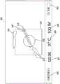
现在转到图3A,示出了由用户界面218产生的示例GUI 300,GUI 300可由计算装置100在显示装置206和/或显示装置110上呈现。GUI 300包括对应于消融探头130的消融天线310的图形表示、对应于超声成像仪140的超声棒320的图形表示、消融探头130的轨迹315的图形表示、超声图像平面325、和投影消融区域指示器330,所述投影消融区域指示器330示出了针对当前消融手术配置的投影消融区域。超声图像平面325将包括基于由超声成像仪140捕获的超声图像数据的超声图像(为了更加清晰示出正在描述的元件,在此未示出所述超声图像)。GUI 300还包括超声探头指示器302和天线指示器303,所述天线指示器303表示超声成像仪140和消融探头130是否连接到计算装置100和系统10。GUI 300还包括配置成用于当前消融手术的时间指示器304、温度指示器306和瓦特数指示器308。Turning now to FIG. 3A , there is shown an
轨迹315示出了消融探头130在患者身体内部导航的轨迹。轨迹315的长度对应于消融探头130的长度。同样,轨迹315的宽度对应于消融探头130的宽度。因此,当将消融探头130和超声成像仪140定位在患者身体外部时,轨迹315将显示能够将消融探头130导航到患者身体中的距离。这样,医师能够确定在将消融探头130插入到患者身体中之前消融探头130是否能够达到患者身体内部的目标组织。
GUI 300可以概略示出消融天线310和轨迹315,使得消融天线310和轨迹315不会遮蔽在超声图像平面325上显示的超声图像。GUI 300还示出了关于超声图像平面325的消融天线310和轨迹315。即,当消融探头130没有与超声图像平面325交叉时,消融天线310示出为阴影(例如,暗灰或者灰色)。例如,如图3A所示,针对在超声图像平面325后方显示的消融天线310的部分消融天线310示出为阴影段310b。同样,轨迹315针对轨迹315的位于超声图像平面325后方的部分示出为阴影段315b。相比,位于超声图像平面325前方的轨迹315a的部分常规示出(具有正常亮度而没有阴影或者暗灰色)。
尽管图3A示出了消融天线310和轨迹315都位于超声图像平面325后方的示例,但是图3B示出了消融天线310和轨迹315都位于超声图像平面325前方的示例。即,消融探头130整体位于由超声成像仪140产生的图像的平面前方但是没有与所述平面交叉。While FIG. 3A shows an example where both
图3C示出了由用户界面218产生的另一个示例GUI 300,所述另一个示例GUI 300可在显示装置206和/或显示装置110上由计算装置100显示。图3C包括多个与图3A和3B中相同的元件。这些元件使用与图3A和3B相同的附图标记表示,并且为了简洁将不再描述。FIG. 3C illustrates another
图3C示出了消融天线310与超声图像平面325共面的示例。在消融天线310的平面和超声图像平面325之间的交叉区域用长圆部340表示。因为消融天线310与超声图像平面325共面,所以长圆部340示出为在消融天线310和轨迹315的两侧上的两条平行线。FIG. 3C shows an example where the
图3D示出了消融天线310与超声图像平面325交叉的示例。与图3C不同,在消融天线310与超声图像平面325共面并且长圆部340延伸了消融天线310和轨迹325的长度的情况中,在图3D中,长圆部340在消融天线310和超声图像平面325之间的交叉区域周围呈现椭圆状。由消融天线310和超声图像平面325之间的交叉角度确定了长圆部340的长度和位置。即,长圆部340示出了消融天线310和超声图像平面325之间的交叉角度的方向和锐度。消融天线310和超声图像平面325之间的交叉点由交叉指示器345示出。FIG. 3D shows an example where the
GUI 300还可示出在计算装置110确定已经开始消融手术之后的消融过程指示器335。消融过程指示器335示出了正在实施的消融手术的过程。消融过程指示器335一开始靠近消融天线310并且随着消融手术的进行向投影消融区域指示器330移动。
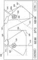
图3E示出了由用户界面218产生的另一个示例GUI 300,该示例GUI 300可以在显示装置206上和/或显示装置110上由计算装置100显示。图3E包括多个与图3A至3D中相同的元件。这些元件使用与图3A至3D相同的附图标记表示,并且为了简洁将不再描述。FIG. 3E illustrates another
图3A至图3D示出了超声图像平面325,其中,超声棒320和超声图像平面325的取向保持为垂直于GUI 300的固定取向。相比之下,图3E根据在由EM场发生器121产生的EM场内的超声图像140的取向示出了超声棒320和超声图像平面327。因此,当医师移动超声成像仪140时,GUI 300中的超声棒320和超声图像平面327的图示根据EM场内的超声成像仪140的运动和角度而变化,从而提供了在其中的消融区域和消融探头130的位置的透视图。FIGS. 3A-3D illustrate an
GUI 300还可以包括透视区域,所述透视区域配置成对应于EM场的包括治疗区域的部分。例如,患者可以定位在台120上,使得由EM场发生器121产生的EM场包括治疗区域。计算装置100然后可以自动和/或在医师的辅助下选择EM场的包括治疗区域的部分,并且可以配置应用程序216和/或GUI 300,以基于消融天线310、超声棒320、超声图像平面327和上述各种其它元件在EM场内的检测位置和/或确定位置在透视区域中示出消融天线310、超声棒320、超声图像平面327和上述各种其它元件。例如,当检测到超声成像仪140位于EM场的配置成在GUI 300的透视区域中显示的部分内时,可以仅仅在透视区域中示出超声图像平面327和超声棒320。同样,当检测到消融探头130定位在EM场的配置成在GUI 300的透视区域中显示的部分内时,可以仅仅在透视区域中示出消融天线310。因此,当超声成像仪140和/或消融探头130没有处于EM场的配置成在GUI 300的透视区域中显示的部分中时,GUI300将不会在透视区域中显示超声棒320、超声图像平面327和/或消融天线310。在消融手术期间,诸如通过移动和/或放大以及缩小,可以调节EM场的配置成在GUI 300的透视区域中显示的部分。
如图3E所示,超声成像仪140倾斜于在GUI 300的透视区域中示出的EM场的部分的平面向左旋转大约90°。这些取向中的差异有助于医师理解超声成像仪140的移动如何影响超声图像平面327和超声图像平面325。如图3E所示,投影消融区域指示器330和/或过程指示器335可以是三维(3D)投影。任一投影消融区域指示器330和/或过程指示器335的3D投影使得更好地理解消融区域如何与消融区域中的所有组织和其它结构相互作用,并且在治疗期间示出了如何在所有方向上吸收能量。此外,这些特征允许医师扫过消融探头130,从而以更大的清晰度确定消融治疗对于治疗区域的效果。As shown in FIG. 3E , the
图4示出了由用户界面218产生的示例GUI 400,示例GUI 400可以在显示装置206和/或显示装置110上由计算装置100显示。图4包括多个与图3A至3E相同的元件。这些元件使用与图3A至3E相同的附图标记表示,并且为了简洁将不再描述。FIG. 4 illustrates an
GUI 400包括如图3A至图3D所示垂直于GUI 300显示的超声图像平面325和超声图像平面327的并排图示,所述超声图像平面327与超声成像仪140在由EM场发生器121产生的EM场内的放置相关地示出。
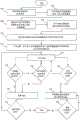
现在参照图5,示出了根据本公开实施例用于实施微波消融手术的示例方法的流程图。在步骤502处,计算装置100接收消融手术配置设置。设置可以由实施消融手术的医师手动输入,或者可以从医师先前输入的预配置的配置设置文件来预加载。消融设置可以基于专门针对患者和/或试图消融的组织类型的特定治疗特点。消融设置可以包括消融时间、温度和瓦特数。一旦接收之后,GUI 300将分别在指示器304、306和308处显示这些消融设置。在题为“治疗手术规划系统和方法”的共同待决临时专利No.14/821,950中更加全面地描述了关于微波消融治疗的规划阶段的其它细节。Referring now to FIG. 5, shown is a flowchart of an example method for performing a microwave ablation procedure in accordance with embodiments of the present disclosure. At
然后,在步骤504处,计算装置100从超声成像仪140接收超声图像数据。超声图像数据可以从超声工作站150中继。接下来或者与步骤504同时地,在步骤506处,计算装置100针对超声成像仪140和消融探头130从EM追踪系统接收EM追踪数据。Then, at
此后,在步骤508处,计算装置100基于EM追踪数据确定消融探头130的轨迹。接下来,在步骤510处,计算装置100确定消融探头130或者消融探头130的轨迹和从超声成像仪140接收的超声图像数据的平面之间的交叉部。此后,在步骤512处,计算装置100产生GUI,所述GUI示出了消融天线310、基于从超声成像仪140接收的超声图像数据的与超声图像平面324相关的轨迹315、以及投影消融区域330,如图3A至图3E和图4所示,如上所述。接下来,在步骤514处,计算装置100在显示装置206和/或显示装置110上显示GUI。Thereafter, at
接下来,在步骤516处,计算装置确定消融探头130的位置是否已经改变。如果是,则计算装置100在步骤520处更新GUI。如果否,则计算装置100在步骤518处确定超声成像仪140的位置是否改变。如果是,则计算装置100在步骤520处更新GUI。如果否,则计算装置在步骤514处继续显示未改变的GUI。步骤516和518可以互换和/或同时地实施,并且将在消融手术期间反复实施。Next, at
在更新GUI之后,计算装置100在步骤522处确定消融手术是否完成。如果是,则处理结束。如果否,则计算装置显示GUI,并且处理返回到步骤514。After updating the GUI,
与步骤516同时地,在步骤524处,计算装置100确定是否已经开始消融处理。如果是,则计算装置100在步骤526处用消融处理过程指示器(例如图3D和3E中示出的指示器335)更新GUI。此后,在步骤528处,计算装置100确定是否已经完成了消融处理。如果是,则处理结束。如果否,则处理返回到步骤526,其中基于消融手术的进程反复更新GUI。Concurrent with
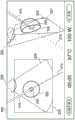
现在参照图6A至图6D,示出了由用户界面218产生的另一个示例GUI 600,GUI 600可以在显示装置206和/或显示装置110上由计算装置100呈现。GUI 600包括多个与参照图3A至图3E在上文描述的元件相同的元件。这些元件用与上述相同的附图标记表示,因此为了简洁将不再详细描述。Referring now to FIGS. 6A-6D , another
参照图6A,GUI 600包括对应于消融探头130的消融天线310的图形图示、对应于超声成像仪140的超声棒320的图形图示、消融探头130的轨迹315的图形图示、包括基于由超声成像仪140捕获的超声图像数据的超声图像326的超声图像平面325、示出了针对当前消融手术配置的投影消融区域的投影消融区域指示器330、和长圆部340,所述长圆部340表示超声天线310的平面和超声图像平面325之间的交叉区域。GUI 600还包括透视区域,所述透视区域基于超声成像仪140的位于EM场的配置成在透视区域中显示的部分内的位置示出了超声棒320的透视图和超声图像平面327、以及消融天线310相对于超声图像平面327的位置,如上参照图3E所述。因为根据超声成像仪140的位置在透视图中显示超声图像平面327,所以可以诸如通过穹顶部330a和/或球形部(如图6D所示)根据投影消融区域的三维透视图显示投影消融区域指示器330。6A,
图6B示出了由用户界面218产生的另一个示例GUI 600,该示例GUI 600可以在显示装置206和/或显示装置110上由计算装置100呈现。如图6B所示,GUI 600以不同于图6A的角度显示超声棒320和消融天线310,从而示出了超声成像仪140和/或消融探头130在EM场内移动可如何导致产生关于GUI 600的不同输出。FIG. 6B illustrates another
图6C示出了由用户界面218产生的另一个示例GUI 600,该GUI 600可在显示装置206和/或显示装置110上由计算装置100呈现。如图6C所示,GUI 600显示了在消融手术期间(例如在经过更多时间之后)根据不同设置和/或不同时间的消融区域指示器330。FIG. 6C illustrates another
图6D示出了由用户界面218产生的另一个示例GUI 600,该示例GUI 600可在显示装置206和/或显示装置110上由计算装置100呈现。如图6D所示,GUI 600将消融区域指示器330显示为定中在消融天线310上的球状。FIG. 6D illustrates another
尽管出于图解和描述的目的已经参照附图详细描述了实施例,但是应当理解的是发明的处理和设备并不受此限制。对于本领域技术人员显而易见的是,可以在不背离本公开的范围的前提下可以对前述实施例作出各种修改。While the embodiments have been described in detail with reference to the accompanying drawings for purposes of illustration and description, it should be understood that the inventive process and apparatus are not so limited. It will be apparent to those skilled in the art that various modifications can be made to the foregoing embodiments without departing from the scope of the present disclosure.
Claims (10)
Translated fromChinesePriority Applications (1)
| Application Number | Priority Date | Filing Date | Title |
|---|---|---|---|
| CN202010079862.3ACN111248998B (en) | 2015-11-17 | 2016-11-17 | System and method for ultrasound image guided ablation antenna placement |
Applications Claiming Priority (4)
| Application Number | Priority Date | Filing Date | Title |
|---|---|---|---|
| US201562256509P | 2015-11-17 | 2015-11-17 | |
| US62/256,509 | 2015-11-17 | ||
| US15/342,157US10548666B2 (en) | 2015-11-17 | 2016-11-03 | Systems and methods for ultrasound image-guided ablation antenna placement |
| US15/342,157 | 2016-11-03 |
Related Child Applications (1)
| Application Number | Title | Priority Date | Filing Date |
|---|---|---|---|
| CN202010079862.3ADivisionCN111248998B (en) | 2015-11-17 | 2016-11-17 | System and method for ultrasound image guided ablation antenna placement |
Publications (2)
| Publication Number | Publication Date |
|---|---|
| CN106691580A CN106691580A (en) | 2017-05-24 |
| CN106691580Btrue CN106691580B (en) | 2020-02-14 |
Family
ID=57345759
Family Applications (2)
| Application Number | Title | Priority Date | Filing Date |
|---|---|---|---|
| CN202010079862.3AActiveCN111248998B (en) | 2015-11-17 | 2016-11-17 | System and method for ultrasound image guided ablation antenna placement |
| CN201611027154.5AActiveCN106691580B (en) | 2015-11-17 | 2016-11-17 | System and method for ultrasound image guided ablation antenna placement |
Family Applications Before (1)
| Application Number | Title | Priority Date | Filing Date |
|---|---|---|---|
| CN202010079862.3AActiveCN111248998B (en) | 2015-11-17 | 2016-11-17 | System and method for ultrasound image guided ablation antenna placement |
Country Status (6)
| Country | Link |
|---|---|
| US (2) | US10548666B2 (en) |
| EP (1) | EP3170456B1 (en) |
| JP (2) | JP6379158B2 (en) |
| CN (2) | CN111248998B (en) |
| AU (2) | AU2016256744B2 (en) |
| CA (1) | CA2948280A1 (en) |
Families Citing this family (26)
| Publication number | Priority date | Publication date | Assignee | Title |
|---|---|---|---|---|
| US10548666B2 (en) | 2015-11-17 | 2020-02-04 | Covidien Lp | Systems and methods for ultrasound image-guided ablation antenna placement |
| US10874327B2 (en)* | 2017-05-19 | 2020-12-29 | Covidien Lp | Systems and methods for tracking and imaging a treatment probe having an integrated sensor |
| US11648062B2 (en)* | 2017-11-09 | 2023-05-16 | Acessa Health Inc. | System for controlling ablation treatment and visualization |
| EP3482690A1 (en)* | 2017-11-14 | 2019-05-15 | Koninklijke Philips N.V. | Ultrasound tracking and visualization |
| WO2019100212A1 (en)* | 2017-11-21 | 2019-05-31 | 深圳迈瑞生物医疗电子股份有限公司 | Ultrasonic system and method for planning ablation |
| EP3720354B1 (en)* | 2017-12-04 | 2025-01-29 | Covidien LP | Automatic ablation antenna segmentation from ct image |
| EP3773232A1 (en) | 2018-04-06 | 2021-02-17 | Medtronic, Inc. | Image-based navigation system and method of using same |
| US11071591B2 (en) | 2018-07-26 | 2021-07-27 | Covidien Lp | Modeling a collapsed lung using CT data |
| US11705238B2 (en) | 2018-07-26 | 2023-07-18 | Covidien Lp | Systems and methods for providing assistance during surgery |
| CN112566581B (en)* | 2018-08-10 | 2024-03-19 | 柯惠有限合伙公司 | System for ablation visualization |
| CN112804959B (en) | 2018-09-28 | 2025-01-28 | 奥瑞斯健康公司 | Robotic systems and methods for accompanying endoscopic and percutaneous medical procedures |
| CN113271881A (en)* | 2019-01-07 | 2021-08-17 | 柯惠有限合伙公司 | System for monitoring ablation progress using a remote temperature probe |
| CN109498155B (en)* | 2019-01-10 | 2022-09-30 | 上海美杰医疗科技有限公司 | Rapid planning system and method in ablation treatment operation |
| EP3911262A1 (en) | 2019-01-18 | 2021-11-24 | Institut Hospitalo-Universitaire De Strasbourg | System and method for medical navigation |
| US20200397511A1 (en) | 2019-06-18 | 2020-12-24 | Medtronic, Inc. | Ultrasound image-based guidance of medical instruments or devices |
| US12089902B2 (en) | 2019-07-30 | 2024-09-17 | Coviden Lp | Cone beam and 3D fluoroscope lung navigation |
| CN110786931B (en)* | 2019-12-03 | 2023-02-28 | 昆山雷盛医疗科技有限公司 | Device and method for enhancing display of ultrasonic image |
| CN110974417A (en)* | 2019-12-13 | 2020-04-10 | 浙江伽奈维医疗科技有限公司 | Integrated navigation intelligent ablation system and method thereof |
| WO2021137108A1 (en) | 2019-12-31 | 2021-07-08 | Auris Health, Inc. | Alignment interfaces for percutaneous access |
| EP4099932B1 (en)* | 2020-02-04 | 2024-04-03 | Covidien LP | Systems and methods for monitoring ablation antenna movement |
| CN111839730B (en)* | 2020-07-07 | 2022-02-11 | 厦门大学附属翔安医院 | Photoacoustic imaging surgical navigation platform for guiding tumor resection |
| US20220354462A1 (en)* | 2021-05-10 | 2022-11-10 | Excera, Inc. | Multiscale ultrasound tracking and display |
| CN113456226A (en)* | 2021-07-30 | 2021-10-01 | 北京迈迪斯医疗技术有限公司 | Interventional navigation system |
| WO2023053334A1 (en)* | 2021-09-30 | 2023-04-06 | オリンパス株式会社 | Processing system and information processing method |
| US12426961B2 (en)* | 2023-09-14 | 2025-09-30 | GE Precision Healthcare LLC | System and method for automatic medical device placement in an anatomical structure using a locking mechanism |
| WO2025090636A1 (en)* | 2023-10-27 | 2025-05-01 | The Government Of The United States, As Represented By The Secretary Of The Army | Ultrasound and machine learning based junctional tourniquet |
Family Cites Families (55)
| Publication number | Priority date | Publication date | Assignee | Title |
|---|---|---|---|---|
| KR19990029038A (en) | 1995-07-16 | 1999-04-15 | 요아브 빨띠에리 | Free aiming of needle ceramic |
| US6122538A (en) | 1997-01-16 | 2000-09-19 | Acuson Corporation | Motion--Monitoring method and system for medical devices |
| US8906010B2 (en) | 1998-02-19 | 2014-12-09 | Mederi Therapeutics, Inc. | Graphical user interface for association with an electrode structure deployed in contact with a tissue region |
| US6106460A (en) | 1998-03-26 | 2000-08-22 | Scimed Life Systems, Inc. | Interface for controlling the display of images of diagnostic or therapeutic instruments in interior body regions and related data |
| US7343195B2 (en) | 1999-05-18 | 2008-03-11 | Mediguide Ltd. | Method and apparatus for real time quantitative three-dimensional image reconstruction of a moving organ and intra-body navigation |
| US6478793B1 (en)* | 1999-06-11 | 2002-11-12 | Sherwood Services Ag | Ablation treatment of bone metastases |
| DE19963440C2 (en) | 1999-12-28 | 2003-02-20 | Siemens Ag | Method and system for visualizing an object |
| JP3875841B2 (en) | 2000-03-28 | 2007-01-31 | アロカ株式会社 | Medical system |
| US6540679B2 (en) | 2000-12-28 | 2003-04-01 | Guided Therapy Systems, Inc. | Visual imaging system for ultrasonic probe |
| US7270634B2 (en) | 2003-03-27 | 2007-09-18 | Koninklijke Philips Electronics N.V. | Guidance of invasive medical devices by high resolution three dimensional ultrasonic imaging |
| US8102392B2 (en) | 2003-06-27 | 2012-01-24 | Kabushiki Kaisha Toshiba | Image processing/displaying apparatus having free moving control unit and limited moving control unit and method of controlling the same |
| JP4664623B2 (en) | 2003-06-27 | 2011-04-06 | 株式会社東芝 | Image processing display device |
| US8123691B2 (en) | 2003-08-19 | 2012-02-28 | Kabushiki Kaisha Toshiba | Ultrasonic diagnostic apparatus for fixedly displaying a puncture probe during 2D imaging |
| JP4167162B2 (en) | 2003-10-14 | 2008-10-15 | アロカ株式会社 | Ultrasonic diagnostic equipment |
| JP2005253742A (en) | 2004-03-12 | 2005-09-22 | Matsushita Electric Ind Co Ltd | Ultrasonic diagnostic equipment |
| US7346382B2 (en) | 2004-07-07 | 2008-03-18 | The Cleveland Clinic Foundation | Brain stimulation models, systems, devices, and methods |
| US7452357B2 (en) | 2004-10-22 | 2008-11-18 | Ethicon Endo-Surgery, Inc. | System and method for planning treatment of tissue |
| US7706860B2 (en) | 2005-04-28 | 2010-04-27 | Boston Scientific Scimed, Inc. | Automated manipulation of imaging device field of view based on tracked medical device position |
| US8632461B2 (en)* | 2005-06-21 | 2014-01-21 | Koninklijke Philips N.V. | System, method and apparatus for navigated therapy and diagnosis |
| ES2524303T3 (en) | 2006-05-08 | 2014-12-05 | C.R. Bard, Inc. | User interface and methods for an ultrasound presentation device |
| US7728868B2 (en) | 2006-08-02 | 2010-06-01 | Inneroptic Technology, Inc. | System and method of providing real-time dynamic imagery of a medical procedure site using multiple modalities |
| US20080033417A1 (en)* | 2006-08-04 | 2008-02-07 | Nields Morgan W | Apparatus for planning and performing thermal ablation |
| EP2104919A2 (en) | 2006-11-27 | 2009-09-30 | Koninklijke Philips Electronics N.V. | System and method for fusing real-time ultrasound images with pre-acquired medical images |
| US8428690B2 (en)* | 2007-05-16 | 2013-04-23 | General Electric Company | Intracardiac echocardiography image reconstruction in combination with position tracking system |
| US9622813B2 (en) | 2007-11-01 | 2017-04-18 | Covidien Lp | Method for volume determination and geometric reconstruction |
| US10524691B2 (en) | 2007-11-26 | 2020-01-07 | C. R. Bard, Inc. | Needle assembly including an aligned magnetic element |
| US20090221908A1 (en) | 2008-03-01 | 2009-09-03 | Neil David Glossop | System and Method for Alignment of Instrumentation in Image-Guided Intervention |
| US8456182B2 (en)* | 2008-09-30 | 2013-06-04 | Biosense Webster, Inc. | Current localization tracker |
| EP2387361B1 (en) | 2009-01-14 | 2020-05-06 | Koninklijke Philips N.V. | Monitoring apparatus for monitoring an ablation procedure |
| JP5397938B2 (en) | 2009-02-16 | 2014-01-22 | ジーイー・メディカル・システムズ・グローバル・テクノロジー・カンパニー・エルエルシー | MEDICAL IMAGE CREATION DEVICE AND PROGRAM |
| US8641621B2 (en) | 2009-02-17 | 2014-02-04 | Inneroptic Technology, Inc. | Systems, methods, apparatuses, and computer-readable media for image management in image-guided medical procedures |
| US8690776B2 (en) | 2009-02-17 | 2014-04-08 | Inneroptic Technology, Inc. | Systems, methods, apparatuses, and computer-readable media for image guided surgery |
| JP5495593B2 (en) | 2009-03-23 | 2014-05-21 | 株式会社東芝 | Ultrasonic diagnostic apparatus and puncture support control program |
| US8556815B2 (en) | 2009-05-20 | 2013-10-15 | Laurent Pelissier | Freehand ultrasound imaging systems and methods for guiding fine elongate instruments |
| US8926605B2 (en) | 2012-02-07 | 2015-01-06 | Advanced Cardiac Therapeutics, Inc. | Systems and methods for radiometrically measuring temperature during tissue ablation |
| EP3175803A1 (en)* | 2009-08-18 | 2017-06-07 | Microfabrica Inc. | Concentric cutting devices for use in minimally invasive medical procedures |
| US9282947B2 (en) | 2009-12-01 | 2016-03-15 | Inneroptic Technology, Inc. | Imager focusing based on intraoperative data |
| ES2900584T3 (en) | 2010-12-23 | 2022-03-17 | Bard Access Systems Inc | System for guiding a rigid instrument |
| KR102143818B1 (en)* | 2011-02-15 | 2020-08-13 | 인튜어티브 서지컬 오퍼레이션즈 인코포레이티드 | Indicator for knife location in a stapling or vessel sealing instrument |
| US8887551B2 (en) | 2011-09-06 | 2014-11-18 | Trig Medical Ltd. | Calibration of instrument relative to ultrasonic probe |
| US8670816B2 (en)* | 2012-01-30 | 2014-03-11 | Inneroptic Technology, Inc. | Multiple medical device guidance |
| JP5889095B2 (en) | 2012-04-13 | 2016-03-22 | ジーイー・メディカル・システムズ・グローバル・テクノロジー・カンパニー・エルエルシー | Puncture planning support apparatus, medical image apparatus, and ultrasonic diagnostic apparatus |
| US8900225B2 (en) | 2012-05-07 | 2014-12-02 | Biosense Webster (Israel) Ltd. | Automatic ablation tracking |
| US8750568B2 (en)* | 2012-05-22 | 2014-06-10 | Covidien Lp | System and method for conformal ablation planning |
| US9439627B2 (en) | 2012-05-22 | 2016-09-13 | Covidien Lp | Planning system and navigation system for an ablation procedure |
| US9439623B2 (en)* | 2012-05-22 | 2016-09-13 | Covidien Lp | Surgical planning system and navigation system |
| US20130317339A1 (en)* | 2012-05-23 | 2013-11-28 | Biosense Webster (Israel), Ltd. | Endobronchial catheter |
| US9993295B2 (en) | 2012-08-07 | 2018-06-12 | Covidien Lp | Microwave ablation catheter and method of utilizing the same |
| JP2014113481A (en) | 2012-11-16 | 2014-06-26 | Toshiba Corp | Ultrasound diagnostic apparatus and image processing method |
| US9119650B2 (en) | 2013-03-15 | 2015-09-01 | Covidien Lp | Microwave energy-delivery device and system |
| JP6282934B2 (en) | 2013-06-11 | 2018-02-21 | キヤノンメディカルシステムズ株式会社 | Ultrasonic diagnostic apparatus and medical image diagnostic apparatus |
| US20150057774A1 (en)* | 2013-08-22 | 2015-02-26 | Novartis Ag | Graphical user interface for surgical console |
| US20150126852A1 (en)* | 2013-11-01 | 2015-05-07 | Covidien Lp | Positioning catheter |
| US20160317230A1 (en) | 2015-04-30 | 2016-11-03 | Covidien Lp | Computer-readable media storing programs for microwave ablation planning and procedure |
| US10548666B2 (en) | 2015-11-17 | 2020-02-04 | Covidien Lp | Systems and methods for ultrasound image-guided ablation antenna placement |
- 2016
- 2016-11-03USUS15/342,157patent/US10548666B2/enactiveActive
- 2016-11-10AUAU2016256744Apatent/AU2016256744B2/ennot_activeCeased
- 2016-11-14CACA2948280Apatent/CA2948280A1/ennot_activeAbandoned
- 2016-11-16JPJP2016223095Apatent/JP6379158B2/ennot_activeExpired - Fee Related
- 2016-11-16EPEP16199097.3Apatent/EP3170456B1/enactiveActive
- 2016-11-17CNCN202010079862.3Apatent/CN111248998B/enactiveActive
- 2016-11-17CNCN201611027154.5Apatent/CN106691580B/enactiveActive
- 2018
- 2018-03-21AUAU2018202024Apatent/AU2018202024B2/ennot_activeCeased
- 2018-07-30JPJP2018142531Apatent/JP6659777B2/enactiveActive
- 2020
- 2020-01-08USUS16/736,907patent/US11596475B2/enactiveActive
Also Published As
| Publication number | Publication date |
|---|---|
| AU2016256744B2 (en) | 2017-12-21 |
| US11596475B2 (en) | 2023-03-07 |
| JP6379158B2 (en) | 2018-08-22 |
| JP2017094084A (en) | 2017-06-01 |
| EP3170456A1 (en) | 2017-05-24 |
| US20200138516A1 (en) | 2020-05-07 |
| US20170135760A1 (en) | 2017-05-18 |
| CN111248998A (en) | 2020-06-09 |
| US10548666B2 (en) | 2020-02-04 |
| AU2018202024A1 (en) | 2018-04-12 |
| CA2948280A1 (en) | 2017-05-17 |
| CN106691580A (en) | 2017-05-24 |
| EP3170456B1 (en) | 2022-08-03 |
| AU2016256744A1 (en) | 2017-06-01 |
| AU2018202024B2 (en) | 2018-11-08 |
| JP6659777B2 (en) | 2020-03-04 |
| JP2018198947A (en) | 2018-12-20 |
| CN111248998B (en) | 2023-03-28 |
Similar Documents
| Publication | Publication Date | Title |
|---|---|---|
| CN106691580B (en) | System and method for ultrasound image guided ablation antenna placement | |
| EP3291736B1 (en) | Microwave ablation planning and procedure systems | |
| CN110192917B (en) | System and method for performing percutaneous navigation procedures | |
| US12257105B2 (en) | System for tracking and imaging a treatment probe | |
| US20230263577A1 (en) | Automatic ablation antenna segmentation from ct image | |
| US20220071703A1 (en) | Systems for monitoring ablation progress using remote temperature probes | |
| US20240090866A1 (en) | System and method for displaying ablation zone progression |
Legal Events
| Date | Code | Title | Description |
|---|---|---|---|
| PB01 | Publication | ||
| PB01 | Publication | ||
| SE01 | Entry into force of request for substantive examination | ||
| GR01 | Patent grant | ||
| GR01 | Patent grant |